KR20190015528A - Shape memory alloy wire attachment structure having an adhesive for a suspension assembly - Google Patents
Shape memory alloy wire attachment structure having an adhesive for a suspension assembly Download PDFInfo
- Publication number
- KR20190015528A KR20190015528A KR1020197000337A KR20197000337A KR20190015528A KR 20190015528 A KR20190015528 A KR 20190015528A KR 1020197000337 A KR1020197000337 A KR 1020197000337A KR 20197000337 A KR20197000337 A KR 20197000337A KR 20190015528 A KR20190015528 A KR 20190015528A
- Authority
- KR
- South Korea
- Prior art keywords
- attachment structure
- adhesive
- wire
- wire attachment
- suspension assembly
- Prior art date
Links
Images


Classifications
-
- G—PHYSICS
- G02—OPTICS
- G02B—OPTICAL ELEMENTS, SYSTEMS OR APPARATUS
- G02B7/00—Mountings, adjusting means, or light-tight connections, for optical elements
- G02B7/02—Mountings, adjusting means, or light-tight connections, for optical elements for lenses
- G02B7/023—Mountings, adjusting means, or light-tight connections, for optical elements for lenses permitting adjustment
-
- F—MECHANICAL ENGINEERING; LIGHTING; HEATING; WEAPONS; BLASTING
- F03—MACHINES OR ENGINES FOR LIQUIDS; WIND, SPRING, OR WEIGHT MOTORS; PRODUCING MECHANICAL POWER OR A REACTIVE PROPULSIVE THRUST, NOT OTHERWISE PROVIDED FOR
- F03G—SPRING, WEIGHT, INERTIA OR LIKE MOTORS; MECHANICAL-POWER PRODUCING DEVICES OR MECHANISMS, NOT OTHERWISE PROVIDED FOR OR USING ENERGY SOURCES NOT OTHERWISE PROVIDED FOR
- F03G7/00—Mechanical-power-producing mechanisms, not otherwise provided for or using energy sources not otherwise provided for
- F03G7/06—Mechanical-power-producing mechanisms, not otherwise provided for or using energy sources not otherwise provided for using expansion or contraction of bodies due to heating, cooling, moistening, drying or the like
- F03G7/061—Mechanical-power-producing mechanisms, not otherwise provided for or using energy sources not otherwise provided for using expansion or contraction of bodies due to heating, cooling, moistening, drying or the like characterised by the actuating element
- F03G7/0614—Mechanical-power-producing mechanisms, not otherwise provided for or using energy sources not otherwise provided for using expansion or contraction of bodies due to heating, cooling, moistening, drying or the like characterised by the actuating element using shape memory elements
- F03G7/06143—Wires
-
- G—PHYSICS
- G02—OPTICS
- G02B—OPTICAL ELEMENTS, SYSTEMS OR APPARATUS
- G02B7/00—Mountings, adjusting means, or light-tight connections, for optical elements
- G02B7/02—Mountings, adjusting means, or light-tight connections, for optical elements for lenses
- G02B7/026—Mountings, adjusting means, or light-tight connections, for optical elements for lenses using retaining rings or springs
-
- G—PHYSICS
- G02—OPTICS
- G02B—OPTICAL ELEMENTS, SYSTEMS OR APPARATUS
- G02B27/00—Optical systems or apparatus not provided for by any of the groups G02B1/00 - G02B26/00, G02B30/00
- G02B27/64—Imaging systems using optical elements for stabilisation of the lateral and angular position of the image
- G02B27/646—Imaging systems using optical elements for stabilisation of the lateral and angular position of the image compensating for small deviations, e.g. due to vibration or shake
-
- G—PHYSICS
- G02—OPTICS
- G02B—OPTICAL ELEMENTS, SYSTEMS OR APPARATUS
- G02B7/00—Mountings, adjusting means, or light-tight connections, for optical elements
- G02B7/02—Mountings, adjusting means, or light-tight connections, for optical elements for lenses
- G02B7/025—Mountings, adjusting means, or light-tight connections, for optical elements for lenses using glue
Abstract
본 개시내용의 실시예는 지지 부재, 지지 부재에 이동 가능하게 결합된 이동 부재, 및 부착 구조물에 의해서 지지 부재와 이동 부재 사이에 결합된 형상기억합금 와이어를 갖는 현가 조립체를 포함한다. 다양한 실시예에 따르면, 부착 구조물은 부착 구조물의 측면에 근접하여 그리고 부착 구조물 사이에 배치되는 접착제 중 적어도 하나를 포함한다.An embodiment of the present disclosure includes a suspension assembly having a support member, a movable member movably coupled to the support member, and a shape memory alloy wire coupled between the support member and the movable member by an attachment structure. According to various embodiments, the attachment structure includes at least one of an adhesive disposed proximate the side of the attachment structure and disposed between the attachment structures.
Description
본 출원은 2017년 6월 9일자로 출원된 미국 특허 출원 제15/618,917호로부터의 우선권을 주장하며, 또한 2016년 6월 9일자로 출원된 미국 가특허 출원 제62/348,084호의 이익을 주장하며, 이들 양자는 그 전문이 본원에 참조로 통합된다.This application claims priority from U.S. Patent Application No. 15 / 618,917, filed June 9, 2017, and also claims benefit of U.S. Provisional Patent Application No. 62 / 348,084, filed June 9, 2016 , Both of which are incorporated herein by reference in their entirety.
실시예는 일반적으로 형상기억합금(SMA) 와이어를 이용하는 현가 조립체에 관한 것이다. 특히, 실시예는, 현가 조립체의 지지 부재를 현가 조립체의 이동 부재에 결합시키는, SMA 와이어를 크림핑하는(crimp) 접착제를 갖는 부착 구조물에 관한 것이다.Embodiments generally relate to suspension assemblies using shape memory alloy (SMA) wires. In particular, embodiments relate to an attachment structure having an adhesive crimping SMA wire that bonds a support member of a suspension assembly to a moving member of a suspension assembly.
다양한 현가 조립체는 현가 조립체의 지지 부재를 현가 조립체의 이동 부재에 결합하기 위해서 SMA 와이어를 이용한다. 예를 들어, SMA 와이어를 이용하는 현가부는 카메라 렌즈 현가 시스템에서 찾아 볼 수 있다. PCT 국제출원 공보 제WO 2014/083318호 및 제WO 2013/175197호는, 굴곡 요소 또는 스프링 판에 의해서 정지적인 지지 조립체 상에서 지지되는 (카메라 렌즈 요소가 장착될 수 있는) 이동 조립체를 가지는 카메라 렌즈 광학 영상 안정화(OIS) 현가 시스템을 개시한다. 인청동과 같은 금속으로 형성된 굴곡 요소는 이동 판 및 굴곡부를 갖는다. 굴곡부는 이동 판과 정지적인 지지 조립체 사이에서 연장되고 스프링으로서 기능하여 정지적인 지지 조립체에 대한 이동 조립체의 이동을 가능하게 한다. 이러한 기계적 기능에 더하여, 굴곡부는 지지 조립체로부터 이동 조립체에 장착된 카메라 렌즈 요소와 같은 구조물까지 전기적 연결부를 제공한다. 이동 조립체 및 지지 조립체는 그러한 조립체들 사이에서 연장되는 형상기억합금(SMA) 와이어에 의해서 결합된다. 각각의 SMA 와이어는 지지 조립체에 부착된 일 단부 및 이동 조립체에 부착된 대향 단부를 갖는다. 현가부는 전기적 구동 신호를 SMA 와이어에 인가하는 것에 의해서 작동된다. 전술한 PCT 공보는 모든 목적을 위해서 본원에서 참조로 포함된다.The various suspension assemblies use SMA wires to couple the support members of the suspension assembly to the moving members of the suspension assembly. For example, a suspension using an SMA wire can be found in a camera lens suspension system. PCT International Application Publication Nos. WO 2014/083318 and WO 2013/175197 disclose camera lens optics having a moving assembly (on which a camera lens element can be mounted) supported on a stationary support assembly by a flexure element or spring plate Discloses an image stabilization (OIS) suspension system. The bending element formed of a metal such as phosphor bronze has a moving plate and a bent portion. The bend extends between the moving plate and the stationary support assembly and functions as a spring to enable movement of the moveable assembly relative to the stationary support assembly. In addition to these mechanical functions, the bends provide electrical connections from the support assembly to a structure, such as a camera lens element, mounted on a moving assembly. The moving assembly and the supporting assembly are joined by a shape memory alloy (SMA) wire extending between such assemblies. Each SMA wire has one end attached to the support assembly and an opposite end attached to the moving assembly. The suspension is operated by applying an electrical drive signal to the SMA wire. The aforementioned PCT publication is incorporated herein by reference for all purposes.
개선된 렌즈 현가부에 대한 지속적인 요구가 있다. 특히, 현가부가 이용될 때 SMA 와이어를 손상시키지 않고 및/또는 손상된 SMA 와이어에 덜 민감한, 전기 신호를 현가부에 결합시키기 위한 개선된 구조를 가지는 그러한 현가 구조물이 요구되고 있다. 매우 기능적이고, 강건하며 효율적으로 제조할 수 있는 이러한 유형의 현가 구조물이 특히 바람직할 것이다.There is a continuing need for improved lens suspension. In particular, there is a need for such a suspension structure that has an improved structure for coupling electrical signals to the suspension without damaging the SMA wire when the suspension is utilized and / or less sensitive to damaged SMA wires. This type of suspension structure, which is very functional, robust and efficient to manufacture, would be particularly desirable.
실시예는, SMA 와이어의 손상 가능성을 줄일 수 있는 방식으로 SMA 와이어를 결합시키는 통합된 전기 트레이스를 가지는 개선된 현가부에 관한 것이다. 현가부는 기능적이고, 강건하며, 효율적으로 제조될 수 있다. An embodiment relates to an improved suspension having integrated electrical traces that combine SMA wires in a manner that reduces the likelihood of damage to the SMA wire. The suspension can be manufactured in a functional, robust, and efficient manner.
일례에서, 현가 조립체는 하나 이상의 제1 와이어 부착 구조물을 포함하는 지지 부재; 하나 이상의 제2 와이어 부착 구조물을 포함하는 이동 부재; 하나 이상의 제1 와이어 부착 구조물 및 하나 이상의 제2 와이어 부착 구조물 중 적어도 하나의 부분들 사이에 배치된 접착제; 및 하나 이상의 제1 와이어 부착 구조물과 하나 이상의 제2 와이어 부착 구조물 사이에서 연장하는 형상기억합금 와이어를 포함하고, 형상기억합금 와이어는 하나 이상의 제1 와이어 부착 구조물, 하나 이상의 제2 와이어 부착 구조물 및 접착제에 결합된다.In one example, the suspension assembly comprises: a support member comprising at least one first wire attachment structure; A movable member including at least one second wire attachment structure; An adhesive disposed between at least one of the at least one first wire attachment structure and the at least one second wire attachment structure; And a shape memory alloy wire extending between the at least one first wire attachment structure and the at least one second wire attachment structure, wherein the shape memory alloy wire comprises at least one first wire attachment structure, at least one second wire attachment structure, Lt; / RTI >
다른 예에서, 현가 조립체는 하나 이상의 제1 와이어 부착 구조물을 포함하는 지지 부재; 하나 이상의 제2 와이어 부착 구조물을 포함하는 이동 부재; 하나 이상의 제1 와이어 부착 구조물과 하나 이상의 제2 와이어 부착 구조물 사이에서 연장되고 이들에 결합되는 형상기억합금 와이어; 및 하나 이상의 제1 와이어 부착 구조물 및 하나 이상의 제2 와이어 부착 구조물 중 적어도 하나의 측면 부근에 있는 형상기억합금 와이어의 일부 상에 배치되는 접착제를 포함한다.In another example, the suspension assembly comprises: a support member comprising at least one first wire attachment structure; A movable member including at least one second wire attachment structure; A shape memory alloy wire extending between and joined to the at least one first wire attachment structure and the at least one second wire attachment structure; And an adhesive disposed on a portion of the shape memory alloy wire near the side of at least one of the at least one first wire attachment structure and the at least one second wire attachment structure.
다른 예에서, 현가 조립체는 하나 이상의 제1 와이어 부착 구조물을 포함하는 지지 부재; 하나 이상의 제2 와이어 부착 구조물을 포함하는 이동 부재; 하나 이상의 제1 와이어 부착 구조물 및 하나 이상의 제2 와이어 부착 구조물의 적어도 하나의 측면으로부터 연장되는 플랫폼 부분; 플랫폼 부분 상에 배치되는 접착제; 및 하나 이상의 제1 와이어 부착 주조물과 하나 이상의 제2 와이어 부착 구조물 사이에서 연장되고, 하나 이상의 제1 와이어 부착 구조물, 하나 이상의 제2 와이어 부착 구조물 및 접착제에 결합되는 형상기억합금 와이어를 포함한다.In another example, the suspension assembly comprises: a support member comprising at least one first wire attachment structure; A movable member including at least one second wire attachment structure; A platform portion extending from at least one side of the at least one first wire attachment structure and the at least one second wire attachment structure; An adhesive disposed on the platform portion; And a shape memory alloy wire extending between the at least one first wire bonded casting and the at least one second wire attachment structure and coupled to the at least one first wire attachment structure, the at least one second wire attachment structure, and the adhesive.
다른 예에서, 접착제를 포함하는 현가 조립체를 제조하는 방법은, 지지 부재를 수용하는 단계로서, 지지 부재는 하나 이상의 제1 와이어 부착 구조물을 포함하는 지지 부재; 하나 이상의 제2 와이어 부착 구조물을 포함하는 이동 부재; 및 하나 이상의 제1 와이어 부착 구조물과 하나 이상의 제2 와이어 부착 구조물에 결합되고 이들 사이에서 연장되는 형상기억합금 와이어를 포함하는, 수용 단계; 하나 이상의 제1 와이어 부착 구조물 및 하나 이상의 제2 와이어 부착 구조물 중 적어도 하나의 측면에 근접하게 접착제를 배치하는 단계; 형상기억합금 와이어에 전기적 구동 신호를 인가하는 단계; 및 접착제를 경화시키는 단계를 포함한다.In another example, a method of making a suspension assembly comprising an adhesive includes the steps of: receiving a support member, wherein the support member comprises: a support member comprising at least one first wire attachment structure; A movable member including at least one second wire attachment structure; And a shape memory alloy wire coupled to and extending between the at least one first wire attachment structure and the at least one second wire attachment structure; Disposing an adhesive proximate at least one side of the at least one first wire attachment structure and the at least one second wire attachment structure; Applying an electrical drive signal to the shape memory alloy wire; And curing the adhesive.
다른 예에서, 접착제를 포함하는 현가 조립체를 제조하는 방법은, 지지 부재를 수용하는 단계로서, 지지 부재는 하나 이상의 제1 와이어 부착 구조물을 포함하는 지지 부재; 하나 이상의 제2 와이어 부착 구조물을 포함하는 이동 부재; 하나 이상의 제1 와이어 부착 구조물 및 하나 이상의 제2 와이어 부착 구조물 중 적어도 하나의 부분들 사이에 배치되는 미경화 접착제; 및 하나 이상의 제1 와이어 부착 구조물과 하나 이상의 제2 와이어 부착 구조물 사이에 연장되고 이들에 결합되는 형상기억합금 와이어를 포함하는, 수용 단계; 형상기억합금 와이어에 전기적 구동 신호를 인가하는 단계; 및 접착제를 경화시키는 단계를 포함한다.In another example, a method of making a suspension assembly comprising an adhesive includes the steps of: receiving a support member, wherein the support member comprises: a support member comprising at least one first wire attachment structure; A movable member including at least one second wire attachment structure; An uncured adhesive disposed between at least one of the at least one first wire attachment structure and the at least one second wire attachment structure; And a shape memory alloy wire extending between and joined to the at least one first wire attachment structure and the at least one second wire attachment structure; Applying an electrical drive signal to the shape memory alloy wire; And curing the adhesive.
다른 예에서, 접착제를 포함하는 현가 조립체를 제조하는 방법은, 지지 부재를 수용하는 단계로서, 지지 부재는 하나 이상의 제1 와이어 부착 구조물을 포함하는 지지부재; 하나 이상의 제2 와이어 부착 구조물을 포함하는 이동 부재; 하나 이상의 제1 와이어 부착 구조물 및 하나 이상의 제2 와이어 부착 구조물 중 적어도 하나의 부분들 사이에 배치되는 제1 미경화 접착제; 하나 이상의 제1 와이어 부착 구조물 및 하나 이상의 제2 와이어 부착 구조물 중 적어도 하나에 근접하게 배치되는 제2 미경화 접착제; 및 하나 이상의 제1 와이어 부착 구조물과 하나 이상의 제2 와이어 부착 구조물 사이에서 연장되는 형상기억합금 와이어를 포함하는, 수용 단계; 및 제2 미경화 접착제를 경화시키는 단계; 및 제1 미경화 접착제를 경화시키는 단계를 포함한다.In another example, a method of making a suspension assembly comprising an adhesive includes the steps of: receiving a support member, wherein the support member comprises: a support member comprising at least one first wire attachment structure; A movable member including at least one second wire attachment structure; A first uncured adhesive disposed between at least one of the at least one first wire attachment structure and the at least one second wire attachment structure; A second uncured adhesive disposed adjacent to at least one of the at least one first wire attachment structure and the at least one second wire attachment structure; And a shape memory alloy wire extending between the at least one first wire attachment structure and the at least one second wire attachment structure; And curing the second uncured adhesive; And curing the first uncured adhesive.
도 1a는 실시예에 따른 현가부의 상단 등각도이다.
도 1b는 도 1a에 도시된 현가부의 상단 평면도이다.
도 2a는 도 1a에 도시된 현가부의 지지 부재의 상단 등각도이다.
도 2b는 도 2a에 도시된 지지 부재의 하단 평면도이다.
도 3a는 도 2a에 도시된 지지 부재의 장착 영역의 구체적인 상단 등각도이다.
도 3b는 도 2a에 도시된 지지 부재의 장착 영역의 구체적인 하단 등각도이다.
도 4a는 도 1a에 도시된 현가부의 이동 부재의 상단 등각도이다.
도 4b는 도 4a에 도시된 이동 부재의 하단 평면도이다.
도 5는 도 4a에 도시된 이동 부재의 굴곡부 아암 장착 영역 및 와이어 부착부의 구체적인 상단 등각도이다.
도 6은 도 4a에 도시된 이동 부재의 굴곡부 아암 장착 영역 및 와이어 부착부의 구체적인 상단 등각도이다.
도 7은 도 1a에 도시된 현가부의 지지 부재 장착 영역 및 굴곡부 아암 장착 영역의 구체적인 상단 등각도이다.
도 8 내지 도 14는 현가부의 실시예의 주석이 달린 도면이다.
도 15a는 실시예에 따른 지지 부재 내로 통합될 수 있는 부착 구조물의 상단 등각도이다.
도 15b는 도 15a에 도시된 부착 구조물의 상단 평면도이다.
도 16은 도 15a 및 도 15b에 도시된 부착 구조물 내로 통합될 수 있는 크림프의 단면도를 도시한다.
도 17은 예시적인 절단 패드를 포함하는 부착 부재의 상단 등각도를 도시한다.
도 18은 다른 예시적인 절단 패드를 포함하는 부착 부재의 상단 등각도를 도시한다.
도 19는 이동 부재 내로 통합될 수 있는 부착 구조물을 도시한다.
도 20a 내지 도 20c는 본원에 개시된 부착 구조물 내로 통합될 수 있는 크림프의 실시예를 도시한다.
도 21은 본 개시내용의 실시예에 따른 이동 부재의 기저부 층을 도시한다.
도 22a 내지 도 24b는 본원에서 개시된 부착 구조물 내로 식각될 수 있는 부분적인 식각 패턴의 실시예를 도시한다.
도 25a 내지 도 25c는 이동 부재 내로 통합될 수 있는 부착 구조물을 도시한다.
도 26a 및 도 26b는 본원에서 개시된 부착 구조물 내로 통합될 수 있는 크림프의 다른 실시예를 도시한다.
도 27a 내지 도 27c는 본원에서 개시된 부착 구조물 내로 통합될 수 있는 크림프의 다른 실시예를 도시한다.
도 28a 및 도 28b는 본원에서 개시된 부착 구조물 내로 통합될 수 있는 크림프의 다른 실시예를 도시한다.
도 29는 본 개시내용의 실시예에 따른 이동 부재의 다른 기저부 층을 도시한다.
도 30은 본원에 개시된 부착 구조물 내로 통합될 수 있는 크림프의 다른 실시예의 상단 등각도를 도시한다.
도 31은 도 30에 도시된 크림프의 평면도를 도시한다.
도 32는 도 30 및 도 31에 도시된 크림프의 도 31의 A-A 축을 따른 단면도를 도시한다.
도 33은 본원에 도시된 이동 부재 내로 통합될 수 있는 부착 구조물을 도시한다.
도 34는 실시예에 따른 고정구 내의 현가 조립체를 도시한다.1A is a top isometric view of a suspension according to an embodiment.
1B is a top plan view of the suspension shown in FIG. 1A.
Fig. 2A is a top isometric view of the supporting member of the suspension shown in Fig. 1A. Fig.
Figure 2B is a bottom plan view of the support member shown in Figure 2A.
Figure 3a is a specific top isometric view of the mounting area of the support member shown in Figure 2a.
Figure 3B is a specific bottom isometric view of the mounting area of the support member shown in Figure 2A.
4A is a top isometric view of the moving member of the suspension shown in FIG. 1A.
4B is a bottom plan view of the moving member shown in FIG. 4A.
Figure 5 is a specific top isometric view of the flex arm mounting area and wire attachment of the shifting member shown in Figure 4a.
Fig. 6 is a specific top isometric view of the bend arm mounting region and wire attachment portion of the shifting member shown in Fig. 4a. Fig.
FIG. 7 is a specific top isometric view of the support member mounting area and flex arm mounting area of the suspension shown in FIG. 1A;
8 to 14 are annotated drawings of the embodiment of the suspension.
15A is a top isometric view of an attachment structure that may be incorporated into a support member according to an embodiment.
15B is a top plan view of the attachment structure shown in FIG. 15A.
Figure 16 shows a cross-sectional view of a crimp that can be incorporated into the attachment structure shown in Figures 15A and 15B.
Figure 17 shows a top isometric view of an attachment member comprising an exemplary cutting pad.
Figure 18 shows a top isometric view of an attachment member comprising another exemplary cutting pad.
Figure 19 shows an attachment structure that can be incorporated into a moving member.
20A-20C illustrate an embodiment of a crimp that can be incorporated into the attachment structure disclosed herein.
Figure 21 illustrates a base layer of a moving member in accordance with an embodiment of the present disclosure.
Figures 22A-B illustrate an embodiment of a partial etch pattern that may be etched into the attachment structure disclosed herein.
25A-25C illustrate an attachment structure that may be incorporated into a moving member.
26A and 26B illustrate another embodiment of a crimp that may be incorporated into the attachment structure disclosed herein.
27A-27C illustrate another embodiment of a crimp that may be incorporated into the attachment structure disclosed herein.
28A and 28B illustrate another embodiment of a crimp that may be incorporated into the attachment structure disclosed herein.
29 illustrates another base layer of a moving member according to an embodiment of the present disclosure;
Figure 30 shows a top isometric view of another embodiment of a crimp that may be incorporated into the attachment structure disclosed herein.
Figure 31 shows a top view of the crimp shown in Figure 30;
32 shows a cross-section along the AA axis of the Fig. 31 of the crimp shown in Figs. 30 and 31;
33 illustrates an attachment structure that may be incorporated into the mobile member shown herein.
34 shows a suspension assembly in a fixture according to an embodiment.
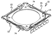
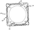
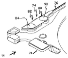
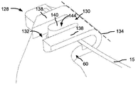
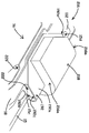
도 1a 및 도 1b는 실시예에 따른 현가 조립체(10)를 도시한다. 도시된 바와 같이, 현가 조립체(10)는 가요성 인쇄 회로(FPC) 또는 지지 부재(12) 및 지지 부재에 결합된 스프링 크림프 회로 또는 이동 부재(14)를 포함한다. 형상기억합금(SMA) 와이어(15)는 지지 부재(12)와 이동 부재(14) 사이에서 연장되고, 지지 부재에 대한 이동 부재의 위치를 이동 및 제어하도록 전기적으로 작동될 수 있다. 다양한 실시예에 따르면, 현가 조립체(10)는, 예를 들어, 휴대 전화기, 태블릿, 랩탑 컴퓨터 내로 통합될 수 있는 카메라 렌즈 광학 영상 안정화(OIS) 장치이다.1A and 1B show a
도 2a, 도 2b, 도 3a 및 도 3b는 지지 부재(12)를 더 구체적으로 도시한다. 도시된 바와 같이, 지지 부재(12)는 기저부 층(16) 및 기저부 층(16) 상의 트레이스(18a 내지 18d)와 같은 복수의 전도성 트레이스(18)를 포함한다. 다양한 실시예에 따르면, 복수의 전도성 트레이스(18)는 지지 부재(12)의 전도체 층 내에 있다. 유전체(20)의 층이 전도성 트레이스(18)와 기저부 층(16) 사이에 위치되어 기저부 층(16)으로부터 트레이스를 전기적으로 절연시킨다. 크림프(24) 같은 복수의 와이어 부착 구조물. 다양한 실시예에 따르면, 도 2a, 도 2b, 도 3a 및 도 3b에 도시된 것과 같이, 정적 크림프로서 구성된 4개의 크림프(24)가 기저부 층(16) 상에 위치된다. 도시된 실시예에 따르면, 크림프(24)는 기저부 층(16)의 주요 평면형 표면 부분(26)으로부터 (예를 들어, z-방향으로) 이격된 레벨에서 기저부 층(16) 내의 턱부(ledge)(25) 상에 일체로 형성된 인접 구조물의 2개의 쌍으로서 구성된다. 다른 실시예는 이것으로 제한되는 것은 아니지만 와이어를 부착하기 위해 사용되는 납땜 패드 및 다른 기계적 구조물을 포함하는 와이어 부착 구조물을 사용하는 것들을 포함한다. 다른 실시예에 따르면, 와이어 부착 구조물은 쌍이 아닌 기저부 층(16)의 턱부(25) 상의 단일 와이어 부착 구조물 같은 다른 배열로 구성된다. 다양한 실시예에 따르면, 베어링-유지 함몰부(28)가 기저부 층(16)의 부분(26) 내에 형성된다. 함몰부(28) 내의 베어링(미도시)은 이동 부재(14)와 맞물리고 이동 부재(14)를 지지 부재(12)에 대해서 이동 가능하게 지지하도록 구성된다. 트레이스(18)는 기저부 층(16) 상의 전도체 층 내에서 단자(30) 및 콘택 패드(32)를 포함한다. 트레이스(18)의 각각이 단자(30)를 콘택 패드(32)에 결합시킨다. 예를 들어, 콘택 패드(32a 및 32b)는 지지 부재(12)의 제1 장착 영역(33)에 위치되고, 트레이스(18a 및 18b)는 단자(30a 및 30b)를 패드(32a 및 32b)에 각각 결합시킨다. 제2 장착 영역(35)에 위치되는 콘택 패드(32)는 트레이스(18)에 의해서 단자(30)에 유사하게 결합된다. 콘택 패드(32)는 도시된 실시예에 따라 크림프(24)의 각각에 위치되고, 콘택 패드의 각각은 분리된 트레이스에 의해서 분리된 단자(30)에 결합된다(예를 들어, 트레이스(18d)는 단자(30d)를 패드(32d)에 결합시킨다). 단자(30)가 위치되는 기저부 층(16)의 부분은 주요 표면 부분(26)의 평면의 외부에 (예를 들어, 도시된 실시예에 따라 주요 표면 부분의 평면에 수직으로) 형성된다.Figures 2a, 2b, 3a and 3b show the
도 3a 및 도 3b는 지지 부재(12)의 장착 영역(33)의 더 구체적인 실시예를 도시한다. 도시된 바와 같이, 장착 영역(33)은 제1 장착 패드(40) 및 제2 장착 패드(42)를 포함한다. 장착 패드(42)는, 기저부 층의 다른 부분으로부터 전기적으로 절연된 기저부 층(16) 내의 섬 또는 패드 부분(44)을 포함한다. 섬 패드 부분(44)은, 기저부 층(16)의 섬 패드 부분(44)과 인접 부분 사이에서 연장되는 유전체(20)의 지역에 의해서 기저부 층(16)의 인접 부분으로부터 부분적으로 지지될 수 있다. 트레이스(18a) 및 콘택 패드(32a)는 섬 패드 부분(44)까지 연장되고, 실시예에서, 장착 패드(42)에서 유전체(20)를 통해서 연장되는 도금된 또는 다른 비아(46)와 같은 전기 연결부에 의해서 섬 패드 부분(44)에 전기적으로 연결된다. 다른 실시예는, 예를 들어, 유전체(20)의 연부에 걸쳐 콘택 패드(32a)와 섬 패드 부분(44) 사이에서 연장되는 전도성 접착제와 같은 다른 전기 연결부를 비아(46) 대신에 또는 그에 부가하여 포함한다. 장착 패드(40)는 장착 패드(42)에 인접하며, 기저부 층(16)의 패드 부분(48), 및 콘택 패드(32b)를 패드 부분(48)에 연결하는 비아(50)와 같은 전기 연결부를 포함한다. 다양한 실시예에 따르면, 패드 부분(48)은 전기 접지 또는 공통 구조물로서 기능하도록 구성된다. 장착 영역(35)은 장착 영역(33)과 유사할 수 있다.3A and 3B show a more specific embodiment of the mounting
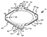
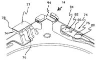
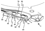
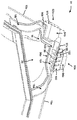
도 4a, 도 4b, 도 5, 도 6 및 도 7은 이동 부재(14)의 실시예를 더 구체적으로 도시한다. 도시된 바와 같이, 이동 부재(14)는 판(60) 및 그러한 판(60)으로부터 연장되는 스프링 또는 굴곡부 아암(62)을 포함한다. 도시된 실시예에 따르면, 판(60)은 직사각형 부재이고, 각각의 굴곡부 아암(62)은 판(60)의 주변부의 2개의 변을 따라서 연장되는 제1 부분(64) 및 제2 부분(66)을 가지는 세장형 부재이다. 다양한 실시예에 따르면, 판(60) 및 굴곡부 아암(62)은 스테인리스강 같은 스프링 금속 기저부 층(68)에 형성된다. 이동 부재(14)는 또한 크림프(70) 같은 와이어 부착 구조물을 포함한다. 다양한 실시예에 따르면, 도 4a, 도 4b, 도 5, 도 6 및 도 7에 도시된 바와 같이, 이동 크림프 같은 4개의 크림프(70)가 쌍으로 구성된다. 도시된 실시예에 따르면, 크림프(70)는 판(60)으로부터 연장되는 아암(72)의 단부 상에서 판(60)과 동일한 스프링 금속 기저부 층(68)과 단일체형이고 그로부터 형성된다. 이동 부재(14)는 다른 실시예에서 달리 구성된다. 예를 들어, 다른 실시예에서, 굴곡부 아암(62)은 달리 성형될 수 있고, 다른 수일 수 있고, 달리 구성될 수 있으며, 및/또는 판(60) 상의 다른 위치로부터 연장될 수 있다. 또 다른 실시예에서, 크림프(70)는 판(60)에 부착된 분리된 구조물로서(즉, 판과 단일체형이 아니게) 형성될 수 있다. 다른 실시예는 이것으로 제한되는 것은 아니지만 와이어를 부착하기 위해 사용되는 납땜 패드 및 다른 기계적 구조물을 포함하는 와이어 부착 구조물을 사용하는 것들을 포함한다. 다른 실시예에 따르면, 와이어 부착 구조물은 쌍이 아닌 아암(72)의 단부 상의 단일 와이어 부착 구조물 같은 다른 배열로 구성된다.Figs. 4A, 4B, 5, 6 and 7 illustrate more specifically the embodiment of the shifting
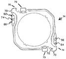
굴곡부 아암(62)의 단부 부분은, 지지 부재(12)의 장착 영역(33 및 35)에 장착되도록 구성된 장착 영역(74)을 갖는다. 기저부 층(68) 상의 전도성 트레이스(76)는 장착 영역(74)으로부터 굴곡부 아암(62) 상에서 연장된다. 다양한 실시예에 따르면, 트레이스(76)는 또한 판(60)의 부분에 걸쳐 기저부 층(68) 상에서 연장된다. 도시된 실시예에 따르면, 아암(72) 상의 트레이스(76)는 또한 판(60) 상의 콘택 패드(77)까지 연장된다. 도시된 실시예에 따르면, 콘택 패드(77)는 판(60)의 주요 평면형 표면의 외부로 연장되는 플랫폼(73) 상에 위치된다. 다른 실시예에서 콘택 패드(77)는 다른 위치(예를 들어, 판(60) 상의 위치)에 있다. 유전체(78)의 층이 전도성 트레이스(76)와 기저부 층(68) 사이에 위치되어 기저부 층(68)으로부터 트레이스(76)를 전기적으로 절연시킨다. 장착 영역(74)은 제1 장착 패드(80) 및 제2 장착 패드(82)를 포함한다. 각각의 장착 패드(82)는, 기저부 층(68)의 다른 부분으로부터 전기적으로 절연되는 기저부 층(68) 내의 섬 또는 패드 부분(84)을 포함한다. 각각의 트레이스(76)는 장착 패드(82)로부터, 장착 패드(80)에 걸쳐 연장된다(그리고 그로부터 전기적으로 절연된다). 도시된 실시예에 따르면서, 장착 패드(80 및 82) 사이에서 연장되는 트레이스(76)의 부분은 굴곡부 아암(62) 상의 트레이스의 부분보다 확대되고, 그에 따라 기저부 층(68) 내의 섬 패드 부분(84)을 위한 지지부를 제공한다. 트레이스(76)는 섬 패드 부분(84)까지 연장되고, 실시예에서, 장착 패드(82)에서 유전체(78)를 통해서 연장되는 도금된 또는 다른 비아(86)와 같은 전기 연결부에 의해서 섬 패드 부분에 전기적으로 연결된다. 다른 실시예는, 유전체(78)의 연부에 걸쳐 트레이스(76)와 섬 패드 부분(84) 사이에서 연장되는 전도성 접착제와 같은 다른 전기 연결부를 비아(86) 대신에 또는 그에 부가하여 포함한다. 장착 패드(80)는, 유전체(78)에 의해서 트레이스(76)로부터 전기적으로 절연된 기저부 층(68) 내의 패드 부분(90)을 포함한다. 도시된 실시예에 따르면, 장착 패드(80 및 82)에 걸친 트레이스(76)의 부분은 원형이고 중심에서 개방되나, 다른 실시예에서 다른 형태를 취할 수 있다.The end portion of the
아마도 도 1a 및 도 7에 가장 잘 도시된 바와 같이, 이동 부재 굴곡부 아암(62)의 장착 영역(74)은 지지 부재(12)의 장착 영역(33 및 35)에 기계적으로 부착된다. 굴곡부 아암(62) 상의 트레이스(76)는 지지 부재(12) 상의 연관된 트레이스(18)에 전기적으로 연결된다. 다양한 실시예에 따르면, 기계적 연결부는, 이동 부재(14)의 기저부 층(68) 내의 패드 부분(84 및 90)과 지지 부재(12)의 기저부 층(16) 내의 상응하는 패드 부분(44 및 48) 사이의 용접부에 의해서 만들어진다. 용접부는, 예를 들어, 패드 부분(84 및 90)에 위치되는 트레이스(76) 내의 개구부를 통해서 만들어질 수 있다. 용접부는 또한 이동 부재(14)의 패드 부분(84 및 90)과 지지 부재(12)의 상응하는 패드 부분(44 및 48) 사이의 전기적 연결을 가능하게 한다. 이러한 전기적 연결에 의해서, 이동 부재(14)의 금속 기저부 층(68), 및 그에 의해서 이동 크림프와 같은 크림프(70)는 비아(50)를 통해 연관된 트레이스(18), 예를 들어, 트레이스(18b)에 공통으로 전기적으로 연결된다. 유사하게, 각각의 굴곡부 아암 트레이스(76)는 비아(46)를 통해 연관된 트레이스(18), 예를 들어 트레이스(18a)에 전기적으로 연결된다. 다른 실시예는 굴곡부 아암(62)을 지지 부재(12)에 기계적으로 장착하기 위한, 및/또는 굴곡부 아암 상의 트레이스(76)를 지지 부재(12) 상의 연관된 트레이스(18)에 전기적으로 연결하기 위한 다른 구조물을 갖는다. 도시된 실시예에 따르면, 전도성 금속 영역(94)은 크림프(70)에서 이동 부재(14)의 금속 기저부 층(68) 상에 직접적으로 위치되어(즉, 전도성 금속 영역(94)과 금속 기저부 층(68) 사이에는 유전체 또는 다른 절연 재료가 존재하지 않는다), 크림프(70)에 의해서 맞물린 금속 기저부 층(68)과 SMA 와이어(15) 사이의 전기적 연결을 향상시킨다.The mounting
이하에서 더 구체적으로 설명되는 바와 같이, 지지 부재(12) 및 이동 부재(14)는 부가적 및/또는 차감적 프로세스로 형성될 수 있다. 기저부 층(16 및/또는 68)은 다양한 실시예에 따라 스테인리스강이다. 다른 실시예에서, 기저부 층(16 및/또는 68)은 인청동과 같은 다른 금속이나 재료이다. 트레이스(18 및 76), 단자(30) 및 콘택 패드(32)는 구리, 구리 합금 또는 다른 전도성 재료로 형성될 수 있다. 폴리이미드 또는 다른 절연 재료가 유전체(20 및 78)로서 이용될 수 있다. 지지 부재(12) 및/또는 이동 부재(14)의 다른 실시예(미도시)는 더 많거나 적은 트레이스(18 및 76)를 가지며, 트레이스(18)는 상이한 배치로 배열될 수 있다. 용접부와 같은, 크림프(24) 이외의 구조물을 이용하여 SMA 와이어(15)를 기저부 층(16)에 부착할 수 있다. 다른 실시예는 더 많거나 적은 크림프(24 및 70)를 가지며, 크림프는 지지 부재(12) 및 이동 부재(14) 각각 상의 상이한 위치에 있을 수 있다.As will be described in more detail below, the
전술한 바와 같이, 현가 조립체(10)는 지지 부재(12)와 이동 부재(14) 사이에서 연장되는 SMA 와이어(15)를 포함한다. SMA 와이어(15)는 부착 구조물을 이용하여 지지 부재(12) 및 이동 부재(14)에 결합된다. 부착 구조물은 크림프, 예를 들어 도 2a 및 도 2b 그리고 도 4a 및 도 4b에 각각 도시된 크림프(24, 70)를 포함할 수 있다. 다양한 실시예에 따르면, 지지 부재(12) 및 이동 부재(14)는 각각 도 1b 및 도 4b에 도시된 바와 같이 대각선 방향 모서리 상의 2개의 턱부(25) 상에 부착 구조물을 각각 포함한다.As discussed above, the
도 8 내지 도 14는 실시예에 따른 개선된 카메라 렌즈 현가 조립체를 도시한다. 현가 조립체는 2개의 일차적인 구성요소 - 기저부 또는 지지 부재(812)(정적 FPC(가요성 인쇄 회로)라고도 칭함), 및 이동/스프링 부재(814)(스프링 크림프 회로라고도 칭함) - 를 갖는다. 도시된 실시예에 따르면, 정적 FPC(기저부 부재(812)) 및 스프링 크림프 회로(이동 부재(814)) 모두는 통합된 리드 구조물이고, 이들은 기저부 금속(816)(도시된 실시예에 따르면, 스테인리스강(SST)) 상에 형성된 리드, 콘택 패드 및 단자(예를 들어, 구리("Cu") 또는 구리 합금 층)와 같은 전기적 구조물을 갖는다. 절연체(818)(예를 들어, 폴리이미드 또는 "폴리")의 층은 기저부 금속(816)으로부터 전기적으로 절연되는 전기적 구조물의 부분들을 분리한다(다양한 실시예에 대해, Cu 층의 다른 부분은 기저부 금속(816)에 또는 그러한 금속 상에 직접적으로 연결된다). 일부 위치에서, 하나 이상의 트레이스(820) 같은 전기적 구조물은, 절연체(818)의 층 내의 개구부를 통해 트레이스(820) 또는 리드 층으로부터 기저부 금속(816)으로 연장되는 전기적 연결부(예를 들어, "비아"(822))에 의해 기저부 금속(816)에 전기적으로 연결될 수 있다. 다양한 실시예에 따르면, 렌즈는 이동 부재(814)에 장착될 수 있다. 다른 실시예에 따르면, 렌즈를 지지하는 자동초점 시스템이 이동 부재(814)에 장착될 수 있다.8-14 illustrate an improved camera lens suspension assembly in accordance with an embodiment. The suspension assembly has two primary component-base or support members 812 (also referred to as a static FPC (flexible printed circuit)), and a movement / spring member 814 (also referred to as a spring crimp circuit). In accordance with the illustrated embodiment, both the static FPC (bottom member 812) and the spring crimp circuit (moving member 814) are integrated lead structures that are formed from a base metal 816 (according to the illustrated embodiment, Such as a lead, a contact pad, and a terminal (e.g., copper ("Cu") or a copper alloy layer) formed on a substrate (eg, steel (SST)). A layer of insulator 818 (e.g., polyimide or "poly") separates portions of the electrical structure that are electrically insulated from the bottom metal 816 (for various embodiments, To
앞서서 주목한 바와 같이, 정적 부재(812) 및 이동 부재(814)는 기저부 금속(816)(예를 들어, SST와 같은 스프링 금속), 절연 층(818), 및 예를 들어 하나 이상의 트레이스(820)를 포함하는 트레이스 층의 중첩되는 층들로 형성될 수 있다. 절연 커버코트가 트레이스 층의 전부 또는 일부 위에 도포될 수 있다. 금(Au) 및/또는 니켈(Ni)과 같은 내식성 금속이 트레이스 층의 부분에 도금되거나 달리 도포되어 내식성을 제공할 수 있다. 포토리소그래피(예를 들어, 패터닝된 및/또는 비패터닝 포토레지스트 마스크의 이용)와 관련된 습식(예를 들어, 화학적) 및 건식(예를 들어, 플라즈마) 식각, 전기 도금 및 무전해 도금, 및 스퍼터링 프로세스와 같은 통상적인 부가적 침착 및/또는 차감적 프로세스와, 기계적 형성 방법(예를 들어, 펀치 및 형태부(form)의 이용)을 이용하여 일 실시예에 따른 정적 부재(812) 및 이동 부재(814)를 제조할 수 있다. 이러한 유형의 부가적 및 차감적 프로세스는, 예를 들어, 디스크 드라이브 헤드 현가부의 제조와 관련하여 공지되어 있고 이용되고 있으며, 모두가 모든 목적을 위해서 본원에서 참조로 포함되는 이하의 미국 특허에서 일반적으로 개시되어 있다: Bennin 등의 명칭이 "듀얼 스테이지 작동 디스크 드라이브 현가부를 위한 낮은 저항의 접지 접합부(Low Resistance Ground Joints for Dual Stage Actuation Disk Drive Suspensions)"인 미국 특허 제8,885,299호, Rice 등의 명칭이 "복수의 트레이스 구성을 가지는 통합된 리드 현가부(Integrated Lead Suspension with Multiple Trace Configurations"인 미국 특허 제8,169,746호, Hentges 등의 명칭이 "통합된 리드 현가부를 위한 다-층 접지 평면 구조물(Multi-Layer Ground Plane Structures for Integrated Lead Suspensions"인 미국 특허 제8,144,430호, Hentges 등의 명칭이 "통합된 리드 현가부를 위한 다-층 접지 평면 구조물"인 미국 특허 제7,929,252호, Swanson 등의 명칭이 "현가 조립체를 위한 귀금속 전도성 리드를 제조하는 방법(Method for Making Noble Metal Conductive Leads for Suspension Assemblies)"인 미국 특허 제7,388,733호", Peltoma 등의 명칭이 "통합된 리드 현가부를 위한 도금된 접지 특징부(Plated Ground Features for Integrated Lead Suspensions)"인 미국 특허 제7,384,531.As noted above,
정적 부재(812)는 일 실시예에 따른 단일-단편 부재이고, 정적 부재(816)의 2개의 대각선 방향 모서리(838)의 각각에서 2개의 부착 구조물(824), 예를 들어 정적 크림프(부착 구조물)(도시된 실시예에 따르면 총 4개의 정적 크림프)를 갖는다. 단자 패드 섹션(826)은, 정적 부재(812)의 표면 위에서 연장되는 트레이스(820)에 연결된 트레이스 층 내의 단자 패드(826a-g)를 포함한다. 도 8 내지 도 14에 도시된 실시예에 따르면, 분리된 트레이스(820)가 4개의 정적 크림프 같은 4개의 부착 구조물(824)의 각각까지 연장된다. 부착 구조물(824)의 각각에는 트레이스(820) 및 하나 이상의 절연 층(818)에 의해 형성된 전기적 콘택 또는 단자(830)가 위치된다. 정적 부재(812)의 상부 표면 상의 형성된 딤플(828)은 이동 부재(814)의 후방 표면과 맞물리고, 활주 계면 베어링으로서 기능하여 정적 부재(812)에 대한 이동 부재(814)의 저마찰 이동을 가능하게 한다. (예를 들어, 전기적 신호를 자동 초점(AF) 조립체에 제공하기 위해서 그리고 공통 또는 접지 신호 경로를 이동 부재(814)의 기저부 층(816)에 제공하기 위해서) 정적 부재(812) 상의 트레이스(820)는 또한 단자 패드(828a-g)를, 이동 부재(814)에 전기적 및 기계적으로 결합된 정적 부재(812) 상의 전기적 패드 위치(832)에 결합시킨다. 비아(822)는 정적 부재(814) 상의 각각의 트레이스(840)를, 받침 부분(842)에 연결된 기저부 층(816)의 부분에 결합시킨다.The
이동 부재(814)는 도 8 내지 도 14에 도시된 실시예에 따른 단일-단편 부재이며, 렌즈 또는 자동 초점 시스템을 지지하기 위한 중앙 부재(832) 및 중앙 부재(832)로부터 연장되는 하나 이상의 스프링 아암(834)(도시된 실시예에 2개)을 포함한다. 이동 부재(814)는 이동 부재(814)의 2개의 대각선 방향 모서리(836)의 각각에서 2개의 이동 크림프 같은 2개의 부착 구조물(824)(도시된 실시예에 따르면, 도합 4개의 이동 크림프가 있다)을 갖는다. (도 8 내지 도 14에 도시된 실시예에서 중앙 부재(832)에 대향되는 스프링 아암(834)의 단부 상의) 기저부 층(818) 내의 받침대 또는 받침 부분(842)은 정적 부재(812) 상의 상응하는 위치(844)에 용접 또는 달리 부착되도록 구성된다. 이동 부재(814) 상의 트레이스(820)는 (예를 들어, 받침 부분(842)을 통해서) 정적 부재(812) 상의 트레이스(840)에 전기적으로 결합되도록 구성되고 신호를 일 실시예에서 자동 초점(AF) 단자 패드인 단자 패드(830)에 결합시킨다. 도 8 내지 도 14에 도시된 실시예에 따르면, 이동 부재(814)의 기저부 층(816)은 이동 부재(814) 상의 부착 구조물(824), 예를 들어 이동 크림프에 부착된 SMA 와이어(846)의 단부까지의 신호 경로로서 이용된다. 상응하는 단자 패드(830)와 이동 부재(814)의 기저부 층(818)까지의 정적 부재(812) 상의 트레이스(840) 사이의 전기 연결부는 스프링 아암(820)의 받침 부분(842)과 정적 부재(812)의 기저부 층(818) 사이의 연결부에 의해 제공된다(실시예에 따르면, 2개의 부재(812, 814)의 SST 층이 전기적으로 결합되고, 실시예에서 공통 접지 전위가 된다).The
이동 부재 굴곡부 아암 상의 트레이스를 가지는 다양한 실시예에 따른 현가부는 중요한 장점을 제공한다. 이는, 예를 들어, 효과적으로 제조 및 조립될 수 있다. 트레이스는 판 또는 이동 부재의 다른 부분에 장착된 구조물에 전기 신호를 결합시키기 위한 효과적인 구조물이다.Suspension in accordance with various embodiments having traces on the moving member bend arm provides significant advantages. This can, for example, be manufactured and assembled effectively. A trace is an effective structure for coupling electrical signals to a structure mounted on a plate or other part of a moving member.
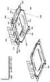
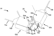
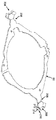
도 15a 및 도 15b는 실시예에 따른 부착 구조물(91)을 도시한다. 다양한 실시예에 따라서, 부착 구조물(91)은 지지 부재(12)의 하나 이상의 대각선 방향 모서리 내로 통합된다. 예를 들어, 부착 구조물(91)은 지지 부재(12)의 2개의 대각선 방향 모서리 내로 통합될 수 있다. 또한, 부착 구조물(91)은 하나 이상의 크림프(92a, 92b)를 이용하여 SMA 와이어(15a 및 15b)와 같은 하나 이상의 SMA 와이어(15)를 크림핑하도록 구성된다.15A and 15B show an
도시된 바와 같이, 부착 구조물(91)은 기저부 층(16)과 단일체형이고 2개의 크림프(92a, 92b)를 포함한다. 2개의 크림프(92a, 92b)는 (도 2a 및 도 2b에 도시된) 주요 평면형 표면 부분(26)으로부터 (예를 들어, z-방향으로) 이격된 레벨에서 기저부 층(16) 내의 턱부(25) 상에 형성된다. 도시된 바와 같이, 각각의 크림프(92a, 92b)는 제1 부분(94a, 94b) 및 제2 부분(96a, 96b)을 포함한다. 제1 부분(94a, 94b)은 제1 부분(94a, 94b) 및 제2 부분(96a, 96b)을 함께 크림핑하기 위해서 각각의 축(97a, 97b)을 따라서 실질적으로 접히도록 구성된다. 일단 함께 크림핑되면, 제1 부분(94a, 94b) 및 제2 부분(96a, 96b)은 크림프(92b) 및 SMA 와이어(15b)에 의해서 도시된 바와 같은 제 위치에서 SMA 와이어(15a 및 15b)를 유지한다. 도 1a 및 도 1b에서 앞서서 도시된 바와 같이, SMA 와이어(15)의 다른 단부는 이동 부재(14)에 결합된다.As shown, the
도시된 바와 같이, 제1 부분(94a, 94b) 및 제2 부분(96a, 96b)은 재료의 단일체형 단편이다. 그러나, 일부 실시예에 따르면, 제1 부분(94a, 94b) 및 제2 부분(96a, 96b)은 비-단일체형일 수 있고, 이하의 도 30a 및 도 30b에서 도시된 바와 같이, 접착제, 용접, 납땜 접합부, 및/또는 기타를 이용하여 함께 결합될 수 있다.As shown, the
크림프(92a)에 의해서 설명되는 바와 같이, 크림프(92a)의 제1 부분(94a)은 전도성 트레이스의 세트(98)를 포함하고, 제2 부분(96a)은 전도성 트레이스(99)의 세트를 포함한다. 다양한 실시예에 따르면, 전도성 트레이스(99)는 전도성 트레이스(18a)로부터 돌출한다. 크림프(92b)가 유사한 구성을 가질 수 있다. 전술한 바와 같이, 전도성 트레이스(18a 및 18b)는 분리된 단자 패드(30a 및 30b)에 각각 결합될 수 있다. 또한, 유전체(100)의 하나 이상의 층이 전도성 트레이스(98, 99)와 기저부 층(16) 사이에 위치되어 트레이스(98, 99)를 기저부 층(16)으로부터 전기적으로 절연시킨다. 다양한 실시예에 따르면, 전도성 트레이스들(98, 99) 사이에 위치된 유전체(100)는 유전체의 단일 단편일 수 있거나; 대안적으로, 축(97a, 97b)을 따라 제1 부분(94a, 94b)을 접는 것을 돕기 위해서, 전도성 트레이스들(98, 99) 사이에 위치된 유전체(100)는 각각 축(97a, 97b)을 따라 (도 15b에 도시된 바와 같은 크림프(92a)를 위한) 파단부를 가질 수 있다. 또한, 실시예에서, 도 15b에 도시된 바와 같이, 트레이스(98, 99)의 길이가 엇갈릴 수 있다. 트레이스(98, 99)의 길이를 엇갈리게 하는 것은, SMA 와이어(15)가 제1 및 제2 부분들(98, 99) 사이의 굽힘부와 접촉할 가능성을 감소시킬 수 있고, 그러한 접촉은 SMA 와이어(15)를 기저부 층(16)에 단락시킬 수 있다. 다양한 실시예에 따르면, 트레이스(98, 99)는 구리, 구리 합금, 또는 다른 전도체로 형성될 수 있다. 다양한 실시예에 따르면, 절연 커버코트가 트레이스(98, 99)의 전부 또는 일부 위에 도포될 수 있다. 금(Au) 및/또는 니켈(Ni)과 같은 내식성 금속이 트레이스(98, 99)의 부분에 도금되거나 달리 도포되어 내식성을 제공할 수 있다. 폴리이미드 또는 다른 절연 재료가 유전체(100)로서 이용될 수 있다. The
유전체(100)의 층이 트레이스(98, 99)를 기저부 층(16)으로부터 절연시키기 때문에 그리고 전도성 트레이스(18a 및 18b)가 각각 분리된 단자 패드(30a 및 30b)에 결합될 수 있기 때문에, 각각의 SMA 와이어(15a 및 15b)는 이동 부재(14)를 이동시키고 제어하기 위해서 독립적으로 작동될 수 있다. 이러한 구성으로 인해서, 기저부 층(16)이 하나의 단편일 수 있다. 대조적으로, 통상적인 실시예는, 각각의 SMA 와이어(15)가 서로 독립적으로 작동될 수 있도록 4개의 단편으로 분할되는 기저부 층을 필요로 할 수 있다. 일부 실시예에 대해 기저부 층(16)이 하나의 단편으로 만들어질 수 있기 때문에, 기저부 층(16)은 하나의 단편으로 만들어질 수 없는 기저부 층보다 다 양호한 구조적 무결성(integrity) 및 강성도를 가질 수 있다.Because the layer of
설명된 바와 같이, 트레이스들(98)은 그 사이에 공간(102)을 포함하고, 트레이스들(99)은 또한 그 사이에 공간(104)을 포함한다. 다양한 실시예에 따르면, 하나 이상의 공간(102)은 하나 이상의 트레이스(99)와 정렬되고, 하나 이상의 공간(104)은 하나 이상의 트레이스(98)와 정렬된다. 다양한 실시예에 따르면, 트레이스(98, 99)는 세장형 특징부, 예를 들어, 핑거, 슬라이스, 부재 및/또는 기타를 포함할 수 있다. 트레이스(98) 및 트레이스(99)는, 예를 들어, 섞여 짜여진 관계, 서로 끼워진 관계, 엇갈린 관계, 및/또는 기타의 관계로 서로에 대해 오프셋되고, 그에 따라, 제1 및 제2 부분(94a, 96a)이 함께 크림핑될 때, 트레이스(98)는 공간(104) 내에 위치되고 트레이스(99)는 공간(102) 내에 위치된다. 크림프(92b)는 크림프(92a)와 유사한 트레이스 및 공간의 구성을 포함할 수 있다. 전술한 바와 같이, 실시예에서, 전도성 트레이스(99)는 도 15a에 도시된 바와 같이 전도성 트레이스(18a)로부터 돌출될 수 있다. 그에 따라, 제1 부분(94a, 94b)이 제2 부분(96a, 96b)과 함께 크림핑될 때, SMA 와이어(15)는 도 16에 도시된 바와 같이 전도성 트레이스(98, 99) 주위로 굽혀진다. As described, the
도 16은 크림프(92b)의 단면도를 도시한다. 다양한 실시예에 따르면, 크림프(92a)의 제1 및 제2 부분(94a, 96a)이 함께 크림핑될 때, 크림프(92a)는 유사한 구성을 가질 수 있다. 도시된 바와 같이, 제1 부분(94b) 및 제2 부분(96b)이 함께 크림핑될 때, 전도성 트레이스(98, 99)는 SMA 와이어(15)의 길이방향 축에 수직인 힘을 제공한다. 그에 따라, SMA 와이어(15)는 트레이스(98, 99)에 의해서 공간(102, 104) 내로 변형된다. 이러한 구성으로 인해서, SMA 와이어(15)가 2개의 편평한 재료의 단편에 의해서 제 위치에서 유지되는 경우보다, SMA 와이어(15)는 크림프(92b)에 의해서 제 위치에서 보다 확실하게 유지될 수 있다.16 shows a cross-sectional view of the
다양한 실시예에 따르면, 전도성 트레이스(98, 99)의 폭(106), 공간(102, 104)의 폭(108), 및 전도성 트레이스(98)와 전도성 트레이스(99) 사이의 거리(110)는 SMA 와이어(15)의 가요성에 따라 달라질 수 있다. 예를 들어, 제1 SMA 와이어(15)가 제2 SMA 와이어(15) 보다 더 경직적이고 제1 SMA 와이어(15)가 이용된다면, 공간(104)의 폭(108)과 전도성 트레이스들(98, 99) 사이의 거리(110)는 제2 SMA 와이어(15)가 이용되는 경우보다 클 수 있다. 다른 예로서, 제1 SMA 와이어(15)가 이용된다면, SMA 와이어(15) 상으로 보다 국소화된 수직 힘을 제공하기 위해서, 트레이스(98)의 폭(106)은 제2 SMA 와이어(15)가 이용되는 경우보다 더 좁을 수 있다.According to various embodiments, the
다양한 실시예에 따르면, 하나 이상의 SMA 와이어(15)가 크림프들(92a, 92b) 사이에서 크림핑된 후에, SMA 와이어(15)는 SMA 와이어(15)의 스풀로부터 절단될 필요가 있을 수 있다. 부가적으로 또는 대안적으로, 크림프(92a, 92b)의 연부를 넘어서 연장될 수 있는 과다 SMA 와이어(15)가 제거될 필요가 있을 수 있다. 다양한 실시예에 따르면, SMA 와이어(15)는, 기저부 층(16) 및/또는 트레이스(18)를 기저부 층(16)으로부터 분리하는 유전체(100) 내의 와이어를 프레스하는 도구를 이용하여 전단될 수 있다. 그러나, 일부 경우에, 이는 SMA 와이어(15)가 기저부 층(16)에 접촉되게 할 수 있고, 기저부 층(16)에 대해서 단락되게 할 수 있다. 그에 따라, 다양한 실시예에 따르면, 패드가 유전체(100)의 상단부 상에 그리고 SMA 와이어(15)의 아래에 배치될 수 있다.According to various embodiments, after one or
도 17 및 도 18은 일 실시예에 따른 예시적인 절단 패드(112a, 112b)를 각각 포함하는 부착 구조물(91)을 도시한다. 전술한 바와 같이, 절단 패드(112a, 112b)는 SMA 와이어(15)를 스풀로부터 절단하기 위해서 및/또는 불필요한 임의의 과다 SMA 와이어(15)를 절단하기 위해서 이용될 수 있다. 이는 SMA 와이어(15)가 기저부 층(16)에 대해서 단락될 가능성을 감소시킬 수 있다. 다양한 실시예에 따르면, 패드(112a, 112b)는 크림프(92a, 92b)의 연부(113a, 113b)에 각각 근접하는 위치에서 턱부(25) 상에 위치될 수 있다. 크림프(92a, 92b)가 크림핑될 때 패드(112a, 112b)가 노출되도록 패드(112a, 112b)가 크림프(92a, 92b)의 외측에 위치될 수 있고, 및/또는 크림프(92a, 92b)가 크림핑될 때 패드(112a, 112b)가 노출되도록 패드(112a, 112b)가 크림프(92a, 92b)의 연부(113a, 113b)를 넘어서 연장되는 부분을 포함할 수 있다. 17 and 18 illustrate an
다양한 실시예에 따르면, 패드(112a, 112b)는 금속으로 만들어질 수 있다. 예를 들어, 패드(112a, 112b)는, 구리, 구리 합금 또는 다른 전도체와 같은, 트레이스(18)와 동일한 재료로 만들어질 수 있다. 그에 따라, 패드(112a)는 도 17에 도시된 바와 같이 트레이스(18)에 결합될 수 있다. 대안적으로, 패드(112b)는 도 18에 도시된 바와 같이 트레이스(18)로부터 결합해제될 수 있다. 다른 실시예에 따르면, 패드(112a, 112b)는 비-금속 재료로 만들어질 수 있고 및/또는 패드(112a, 112b) 위의 커버코트를 포함할 수 있다. According to various embodiments, the
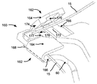
도 19는, 일 실시예에 따른 이동 부재(14) 내로 통합될 수 있는 부착 구조물(114)을 도시한다. 도시된 바와 같이, 부착 구조물(114)은 2개의 크림프(115)를 포함한다. 2개의 크림프(115)는 판(60)과 단일체형이고, 각각의 크림프(115)는 제1 부분(116) 및 제2 부분(118)을 포함한다. 제1 부분(116) 및 제2 부분(118)을 함께 크림핑되게 하기 위해서, 제1 부분(116)은 각각의 축(120a, 120b)을 따라서 실질적으로 접히도록 구성된다. 제1 및 제2 부분(116, 118)이 함께 크림핑될 때, 그들은 SMA 와이어(15)를 제 위치에서 유지한다. 도 1a 및 도 1b에서 앞서서 도시된 바와 같이, SMA 와이어(15)의 다른 단부가 지지 부재(12)에 결합된다.FIG. 19 illustrates an
제1 및 제2 부분(116, 118)은 판(60) 상에 배치된 세장형 특징부(122a 내지 122d)를 포함한다. 또한, 세장형 특징부(122a 내지 122d)는 공간(124a 내지 124d)을 그 사이에 포함한다. 다양한 실시예에 따르면, 공간(124a 내지 124d)의 하나 이상이 세장형 특징부(122a 내지 122d)의 하나 이상과 정렬된다. 다양한 실시예에 따르면, 세장형 특징부(122a 내지 122d)는, 예를 들어, 핑거, 슬라이스, 부재 및/또는 기타일 수 있다. 세장형 특징부(122a, 122b) 및 세장형 특징부(122c, 122d)는, 예를 들어, 섞여 짜여진 관계, 서로 끼워진 관계, 엇갈린 관계, 및/또는 기타의 관계로 서로에 대해 오프셋되고, 그에 따라, 제1 및 제2 부분(116, 118)이 함께 크림핑될 때, 세장형 특징부(122a, 122b)는 공간(124c, 124d) 내에 위치되고 세장형 특징부(122c, 122d)는 공간(124a, 124b) 내에 위치된다. 그에 따라, 제1 부분(116)이 제2 부분(118)과 함께 크림핑될 때, 세장형 특징부(122a 내지 122d)는 SMA 와이어(15)의 길이방향 축에 수직인 힘을 제공한다. 그에 따라, SMA 와이어(15)는 세장형 특징부(122a 내지 122d)에 의해서 공간(124a 내지 124d) 내로 변형된다. 이러한 구성으로 인해서, SMA 와이어(15)가 2개의 편평한 재료의 단편에 의해서 제 위치에서 유지되는 경우보다, SMA 와이어(15)는 크림프(115)에 의해서 제 위치에서 보다 확실하게 유지될 수 있다.The first and
다양한 실시예에 따르면, 세장형 특징부(122a 내지 122d)는 전도성 재료 또는 유전체로 만들어질 수 있다. 예를 들어, 세장형 특징부(122a 내지 122d)는 구리, 구리 합금 또는 다른 전도체, 또는 폴리이미드나 다른 절연 재료로 형성될 수 있다.According to various embodiments,
다양한 실시예에 따르면, 전도성 층(126)은 세장형 특징부(122) 상에 배치될 수 있다. 그러나, 세장형 특징부(122)의 부분이 공간(124a 내지 124)을 포함하기 때문에, 세장형 특징부(122a 내지 122d)가 유전체로 만들어질 때, SMA 와이어(15)는 전도성 층(126)을 통해서 판(60)에 전기적으로 결합될 수 있다. 전술한 공간(104)의 폭(108) 및 전도성 트레이스들(98, 99) 사이의 거리(110)와 유사하게, 세장형 특징부(122a 내지 122d)의 폭 및 공간(124a 내지 124d)의 폭은 SMA 와이어(15)의 가요성에 따라서 달라질 수 있다. 다양한 실시예에 따르면, 전도성 층(126)은 구리, 구리 합금, 또는 다른 전도체로 형성될 수 있다. 다양한 실시예에 따르면, 절연 커버코트가 전도성 층(126)의 전부 또는 일부 위에 도포될 수 있다. 금(Au) 및/또는 니켈(Ni)과 같은 내식성 금속이 전도성 층(126)의 부분에 도금되거나 달리 도포되어 내식성을 제공할 수 있다. 폴리이미드 또는 다른 절연 재료가 세장형 특징부(122)로서 이용될 수 있다. According to various embodiments, the
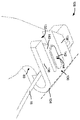
도 20a 내지 도 20c는 본원에서 개시된 하나 이상의 부착 구조물 내로 통합될 수 있는 크림프(128)의 다른 실시예를 도시한다. 다양한 실시예에 따르면, 다중 크림프(128)가 이동 부재(14)의 하나 이상의 대각선 방향 모서리의 각각 내로 통합될 수 있다. 예를 들어, 4개의 크림프(128), 즉 각각의 대각선 방향 모서리에 대한 2개의 크림프(128)가 도 21에 도시된 바와 같이, 이동 부재(14)의 2개의 대각선 방향 모서리 내로 통합될 수 있다.20A-20C illustrate another embodiment of a
도시된 바와 같이, 크림프(128)는 판(60)과 단일체형이고 제1 부분(130) 및 제2 부분(132)을 포함한다. 제1 부분(130)은 제1 및 제2 부분(130, 132)을 함께 크림핑하기 위해서 실질적으로 축(134)을 따라서 접히도록 구성된다. 제1 및 제2 부분(130, 132)이 함께 크림핑될 때, 그들은 도 20b 및 도 20c에 도시된 바와 같이 SMA 와이어(15)를 제 위치에서 유지한다. 도 1a 및 도 1b에서 앞서서 도시된 바와 같이, SMA 와이어(15)의 다른 단부가 지지 부재(12)에 결합된다.As shown, the
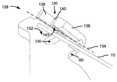
실시예에서, 크림프(128)는 함몰부(136)를 포함한다. 함몰부(136)는 도 20a에 도시된 바와 같이 판(60)의 제2 부분(132)에서 식각될 수 있다. 또한, 제1 부분(130)은 복수의 세장형 부재(138, 140)를 포함할 수 있고, 그러한 세장형 부재들은 그 사이에 공간을 포함한다. 3개의 세장형 부재(138, 140)가 도시되었지만, 대안적인 실시예는 그보다 많거나 적은 세장형 부재(138, 140)를 포함할 수 있다. 제1 및 제2 부분(130, 132)이 함께 크림핑될 때, 세장형 부재 중 적어도 하나, 예를 들어 세장형 부재(140)가 함몰부(136) 내로 연장된다. 단지 하나의 세장형 부재(140)가 함몰부(136) 내로 연장되어 도시되어 있지만, 다른 실시예에서, 다른 세장형 부재들이 각각의 함몰부 내로 또는 동일한 함몰부 내로 연장될 수 있다. 또한, 제1 및 제2 부분(130, 132)이 함께 크림핑될 때, 세장형 부재(138)는 도 20b 및 도 20c에 도시된 바와 같이 제2 부분(132)의 상단부와 접촉될 수 있다. 다양한 실시예에 따르면, 함몰부(136)의 연부 및 세장형 부재(138, 140)의 연부가 둥글게 처리될 수 있고, 그에 따라 SMA 와이어(15)가 세장형 부재(140)에 의해서 함몰부(136) 내로 강제될 때, SMA 와이어(15)가 손상될 가능성이 적어진다.In an embodiment, the
세장형 부재(140)가 함몰부(136) 내로 연장되기 때문에, 세장형 부재(140)는, 제1 및 제2 부분(130, 132)이 함께 크림핑될 때, SMA 와이어(15)의 길이방향 축에 수직인 힘을 제공한다. 그에 따라, SMA 와이어(15)는 세장형 부재(140)에 의해서 함몰부(136) 내로 변형된다. 이러한 구성으로 인해서, SMA 와이어(15)가 2개의 편평한 재료의 단편에 의해서 제 위치에서 유지되는 경우보다, SMA 와이어(15)는 크림프(128)에 의해서 제 위치에서 보다 확실하게 유지될 수 있다.The
다양한 실시예에 따르면, 세장형 부재(140)가 함몰부(136) 내로 연장되도록 및/또는 세장형 부재(140)가 달리 연장될 수 있는 것보다 더 세장형 부재(140)가 함몰부(136) 내로 연장되도록, 세장형 부재(140)는 세장형 부재(140)의 하단부 측면(143) 및/또는 상단부 측면(144)(도 20c에 도시됨) 상에서 부가적인 재료의 층(142)을 포함할 수 있다. 따라서, 편평한 크림핑 도구를 이용하여 제1 및 제2 부분(130, 132)을 함께 크림핑할 수 있다. According to various embodiments, the
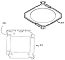
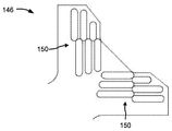
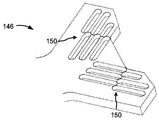
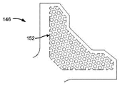
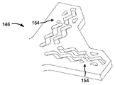
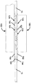
도 21은 다양한 실시예에 따른 이동 부재(14)의 기저부 층(60)을 도시한다. 도시된 바와 같이, 기저부 층(60)은 실질적으로 평면형일 수 있고 부착 구조물(146)을 포함할 수 있다. 다양한 실시예에 따르면, 판(60)의 2개의 대각선 방향 모서리(148)는 2개의 부착 구조물(146)을 포함할 수 있다. 각각의 부착 구조물(146)은 크림프, 예를 들어 도 19 및 도 20a 내지 도 20c에 각각 도시된 크림프(115, 128)를 포함할 수 있다. 부가적으로 또는 대안적으로, 판(60)의 부착 구조물(146)은 하나 이상의 함몰부, 예를 들어 복수의 함몰부의 어레이, 하나 이상의 식각 패턴 및/또는 부분적인 식각 패턴의 어레이를 포함할 수 있다. 부착 구조물(146) 내에 포함된 하나 이상의 함몰부는, SMA 와이어(15)가 2개의 편평한 재료의 단편에 의해서 제 위치에서 유지되는 경우보다, 더 확실하게 SMA 와이어(15)를 유지할 수 있다. 도 8 내지 도 14와 관련하여 전술한 식각 방법의 하나 이상이 식각 패턴을 생성하기 위해서 이용될 수 있다. 다양한 실시예에 따르면, 유전체 및 전도성 층이 식각 패턴 위에 배치될 수 있다. 식각 패턴이 만들어진 후에, 부분적인 식각 패턴의 모서리를 둥글게 처리하여 SMA 와이어(15)의 손상 가능성을 줄일 수 있다.Figure 21 shows the
도 22a 내지 도 24b는 부착 구조물(146) 내로 식각될 수 있는 부분적인 식각 패턴의 실시예를 도시한다. 도 22a 내지 도 24b에 도시된 실시예의 각각에서, 부착 구조물(146)에 고정된 SMA 와이어(15)가 부분적인 식각 패턴에 의해서 변형될 수 있다. 그에 따라, SMA 와이어(15)가 2개의 편평한 재료의 단편에 의해서 제 위치에서 유지되는 경우 보다, SMA 와이어(15)는 부착 구조물(146)에 의해서 제 위치에서 보다 확실하게 유지될 수 있다. FIGS. 22A-B illustrate an embodiment of a partial etch pattern that may be etched into an
일례로서, 도 22a 및 도 22b에 도시된 바와 같이, 부분적인 식각 패턴(150)은 엇갈린 선형 함몰부일 수 있다. 다양한 실시예에 따르면, 부착 구조물(146)에 포함된 크림프가 크림핑될 때, 부분적인 식각 패턴들(150)은, 예를 들어, 섞여 짜여져, 서로 끼워져, 엇갈려, 및/또는 기타로 서로에 대해 오프셋될 수 있다. 다른 예로서, 도 23a 및 도 23b에 도시된 바와 같이, 부분적인 식각 패턴(152)이 함몰부의 어레이일 수 있다. 또 다른 예로서, 도 24a 및 도 24b에 도시된 바와 같이, 부분적인 식각 패턴(154)이 평행한 지그-재그일 수 있다.As an example, as shown in FIGS. 22A and 22B, the
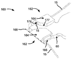
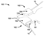
도 25a 내지 도 25c는 일 실시예에 따른 이동 부재(14) 내로 통합될 수 있는 부착 구조물(160)을 도시한다. 다양한 실시예에 따르면, 이하에서 설명되는 부착 구조물(160)의 특징부가 본원에서 설명된 다른 부착 구조물 내에 통합될 수 있다. 도시된 바와 같이, 부착 구조물(160)은 2개의 크림프(162)를 포함한다. 크림프(162)는 판(60)과 단일체형이고 제1 부분(164) 및 제2 부분(166)을 포함한다. 제1 부분(164)은 제1 및 제2 부분(164, 166)을 함께 크림핑하기 위해서 축(168)을 따라서 실질적으로 접히도록 구성된다. 제1 및 제2 부분(164, 166)이 함께 크림핑될 때, 그들은 SMA 와이어(15)를 제 위치에서 유지할 수 있다. 도 1a 및 도 1b에서 앞서서 도시된 바와 같이, SMA 와이어(15)의 다른 단부가 지지 부재(12)에 결합된다.25A-25C illustrate an
예시된 바와 같이, 제1 부분(164)은 함몰부(170)를 포함하고, 제2 부분(166)은 세장형 부재(172)를 포함한다. 제1 및 제2 부분(164, 166)이 함께 크림핑될 때, 세장형 부재(172)가 함몰부(170) 내로 연장된다. 제1 및 제2 부분(164, 166)이 함께 크림핑될 때, 세장형 부재(172)에 의해서 SMA 와이어(15)가 함몰부(170) 내로 변형된다. 이러한 구성으로 인해서, SMA 와이어(15)가 2개의 편평한 재료의 단편에 의해서 제 위치에서 유지되는 경우 보다, SMA 와이어(15)는 크림프(162)에 의해서 보다 확실하게 유지될 수 있다. 다양한 실시예에 따르면, 연부(176)는 그러한 연부(174)를 넘어서 연장되는 부분(177)을 포함할 수 있고, 그에 따라, 제1 및 제2 부분(164, 166)이 함께 크림핑될 때, 도 25b 및 도 25c에 도시된 바와 같이, 제1 부분(164)이 제2 부분(166)에 끼워진다.As illustrated, the
또한, 제1 부분(164)은 연부(174)를 포함하고, 제2 부분(166)은 연부(174)로부터 오프셋된 연부(176)를 포함한다. 제1 및 제2 부분(164, 166)이 함께 크림핑될 때, 연부(174, 176)는 SMA 와이어(15)를 단절시킬 수 있는 절단 연부를 생성하도록 구성된다. 도 25b는 양 크림프(162)가 폐쇄된 부착 구조물(160)을 도시하고, 도 25c는 연부(174, 176)가 SMA 와이어(15)의 단부 부분을 절단한 후의 부착 구조물(160)을 도시한다. The
도 26a 및 도 26b는 본 개시내용의 실시예에 따른 크림프(178)의 다른 실시예를 도시한다. 앞서서 도시한 크림프와 유사하게, 크림프(178)는 앞서서 도시한 이동 부재(14) 및/또는 부착 구조물 내로 통합될 수 있다. 크림프(178)는 판(60)과 단일체형이고, 함께 접히도록 구성된 제1 및 제2 부분(180, 182)을 포함한다. 도 26b에 도시된 바와 같이, 제1 및 제2 부분(180, 182)이 함께 접힐 때, 그들은 SMA 와이어(15)를 제 위치에서 크림핑할 수 있다. 26A and 26B illustrate another embodiment of a
도시된 바와 같이, 크림프(178)는 식각된 함몰부(184)를 포함한다. 함몰부(184)는, 제1 및 제2 부분(180, 182)이 함께 크림핑될 때, 크림프(178)가 굽혀지는 곳(186)에 실질적으로 위치된다. 또한, 함몰부(184)는 굽힘부(186)의 외부 부분 상에 위치된다. 함몰부(184)는 굽힘부(186) 상의 응력을 낮출 수 있고, 이는, 제1 및 제2 부분(180, 182)이 함께 크림핑될 때 판(60)이 균열될 가능성을 감소시킬 수 있다. 다양한 실시예에 따르면, 이는, 판(60)이 더 두꺼운 금속으로 제조될 때 및/또는 판(60)이 작은 전성 및/또는 작은 가단성의 금속으로 제조될 때 유리할 수 있다. 다양한 실시예에 따르면, 함몰부(184)는 도 8 내지 도 14와 관련하여 전술한 식각 방법과 같은 식각에 의해서 형성될 수 있다.As shown, the
다양한 실시예에 따르면, 식각된 함몰부(184)와 유사한 식각된 함몰부가 지지 부재(12) 내에 포함될 수 있다. 즉, 예를 들어, 식각된 함몰부는, 제1 부분(94a, 94b) 및 제2 부분(96a, 96b)이 함께 크림핑될 때 크림프(92a 및 92b)가 굽혀지는 곳에 실질적으로 위치될 수 있다.According to various embodiments, an etched depression similar to the etched
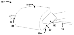
도 27a 내지 도 27c는 일 실시예에 따른 크림프(187)의 다른 실시예를 도시한다. 본원에서 설명한 크림프와 유사하게, 크림프(187)는, 지지 부재(12), 이동 부재(14), 및/또는 지지 및 이동 부재(12, 14) 각각과 관련하여 본원에서 도시한 부착 구조물 내로 통합될 수 있다. 도 27a 내지 도 27c에 도시된 실시예에 따르면, 크림프(187)는 판(60)과 단일체형이고, 함께 접히도록 구성된 제1 및 제2 부분(188, 190)을 포함한다. 도시된 바와 같이, 제1 및 제2 부분(164, 166)이 함께 접힐 때, 그들은 SMA 와이어(15)를 제 위치에서 크림핑할 수 있다.27A-27C illustrate another embodiment of a
크림프(187)는, 크림프(187)의 적어도 하나의 측면으로부터 연장되며 SMA 와이어(15)를 지지하고 및/또는 SMA 와이어(15) 상으로 클림핑 힘을 제공하는, 변형 완화 부재(192)를 포함한다. 도시된 바와 같이, 변형 완화 부재(192)는 크림프(187)의 양 측면으로부터 연장되나; 다른 실시예에 따르면, 변형 완화 부재(192)는 크림프(187)의 일 측면으로부터만 연장된다. Crimp 187 includes
통상적인 실시예에서, 현가 조립체(10)가 응력하에 있을 때, SMA가 크림프의 측면을 빠져나가는 곳에 필연적인 큰 응력 지역이 위치되기 때문에, SMA 와이어가 크림프의 측면을 빠져나가는 곳 가까이에서 SMA 와이어(15)가 손상 및/또는 파괴될 수 있다. 현가 조립체(10)가 응력하에 있을 때 변형 완화 부재(192)가 SMA 와이어(15)와 함께 굽혀질 수 있고, 그에 의해서 SMA 와이어(15)의 굽힘 반경을 증가시키기 때문에, 변형 완화 부재(192)는 SMA 와이어(15) 상의 응력을 감소시킨다. 즉, 예를 들어 각도(θ)로 굽혀질 수 있는 폭(x)을 가지는 SMA 와이어(15)의 섹션 대신에, 변형 완화 부재(192)는 각도(θ)로 굽혀지는 섹션의 폭을, 예를 들어, 2*x, 3*x, 4*x, 등으로 증가시킬 수 있다. 이는 SMA 와이어(15) 상의 응력을 SMA 와이어(15)의 더 큰 부분에 걸쳐 분산시킨다. 다양한 실시예에 따르면, 변형 완화 부재(192)가 크림프(187)의 측면으로부터 돌출되는 거리는, 예를 들어, SMA 와이어(15)를 위해서 사용된 재료의 유형, 강성 및/또는 두께에 따라서 달라질 수 있다.In a typical embodiment, when the
다양한 실시예에 따르면, 변형 완화 부재(192)는 금속으로 제조될 수 있다. 예를 들어, 변형 완화 부재(192)는, 구리, 구리 합금 또는 다른 전도체와 같은, 트레이스(18)와 동일한 재료로 제조될 수 있다. 그에 따라, 변형 완화 부재(192)는 트레이스(18)에 결합될 수 있다. 다양한 실시예에 따르면, 절연 커버코트가 변형 완화 층(192)의 전부 또는 일부 위에 도포될 수 있다. 금(Au) 및/또는 니켈(Ni)과 같은 내식성 금속이 변형 완화 층(192)의 부분에 도금되거나 달리 도포되어 내식성을 제공할 수 있다. 부가적으로 또는 대안적으로, 변형 완화 부재(192)는 유전체로 제조될 수 있다. 예를 들어, 변형 완화 부재(192)는 본원에서 설명된 바와 같은 유전체와 동일한 재료로 만들어질 수 있다. 유전체의 예는 폴리이미드 또는 다른 절연 재료를 포함할 수 있다. 부가적으로 또는 대안적으로, 도 27b 및 도 27c에 도시된 바와 같이, 변형 완화 부재(192)는 변형 완화부의 내부에 금속 패드(194)를 포함할 수 있다. 다양한 실시예에 따르면, 금속 패드(194)는 SMA 와이어(15)를 파지하는데 도움을 줄 수 있고 SMA 와이어(15)가 변형 완화 부재(192)로부터 활주 이탈될 수 있는 가능성을 감소시키는데 도움을 줄 수 있다.According to various embodiments, the
도 28a 내지 도 28b는 크림프(196)의 다른 실시예를 도시한다. 앞서서 도시한 크림프와 유사하게, 크림프(196)는, 지지 부재(12), 이동 부재(14), 및/또는 지지 및 이동 부재(12, 14) 각각과 관련하여 본원에서 도시한 부착 구조물 내로 통합될 수 있다. 크림프(196)는 함께 접히도록 구성된 2개의 부분, 즉 제1 부분(198) 및 제2 부분(200)을 포함한다. 제1 및 제2 부분(198, 200)이 함께 접힐 때, 그들은 SMA 와이어(15)를 제 위치에서 크림핑할 수 있다. 크림프(196)의 유지 강도 증가를 위해서 및/또는 지지 부재(10)가 응력하에 있을 때 SMA 와이어(15) 상의 변형을 감소시키기 위해서, 전술한 실시예의 하나 이상이 크림프(196) 내에 통합될 수 있다.28A-28B illustrate another embodiment of a
제2 부분(200)은 판(60)과 단일체형일 수 있다. 제1 부분(198)은 제2 부분(200)과 비-단일체형이나, 접착제, 용접, 납땜 접합부, 및/또는 기타를 이용하여 제2 부분(200)에 결합될 수 있다. 제1 및 제2 부분(198, 200)은 SMA 와이어(15)의 어느 한 측면 상에 함께 결합될 수 있다. 즉, 실시예에서, 제1 및 제2 부분(198, 200)은 크림프(196)의 내부 측면(202) 상에 또는 크림프의 외부 측면(204) 상에 결합될 수 있다.The
도 29는 본 개시내용의 실시예에 따른 이동 부재(14)의 기저부 층(60)을 도시한다. 도시된 바와 같이, 기저부 층(60)은 실질적으로 평면형일 수 있고 부착 구조물(206)을 포함할 수 있다. 다양한 실시예에 따르면, 판(60)의 2개의 대각선 방향 모서리(208)는 2개의 부착 구조물(206)을 포함할 수 있다. 각각의 부착 구조물(206)은 크림프(210), 예를 들어 도 28a 및 도 28b에 도시된 크림프(196)를 포함할 수 있다. 예를 들어, 부착 구조물(206) 내에 포함된 크림프(210)는, 제2 부분(214)과 비-단일체형이지만, 접착제, 용접, 납땜 접합부, 및/또는 기타를 이용하여 제2 부분(214)에 결합될 수 있는 제1 부분(212)을 포함할 수 있다. 부가적으로 또는 대안적으로, 판(60)의 부착 구조물(206)은 식각 패턴을 포함할 수 있다. 부착 구조물(206) 내에 포함된 식각 패턴은, SMA 와이어(15)가 2개의 편평한 재료의 단편에 의해서 제 위치에서 유지되는 경우 보다, 더 확실하게 SMA 와이어(15)를 유지할 수 있다. 도 8 내지 도 14와 관련하여 전술한 식각 방법의 하나 이상이 본원에서 설명된 실시예와 같은 식각 패턴을 생성하기 위해서 이용될 수 있다. 다양한 실시예에 따르면, 유전체 및 전도성 층이 식각 패턴 위에 배치될 수 있다. 식각 패턴이 만들어진 후에, 부분적인 식각 패턴의 모서리를 둥글게 처리하여 SMA 와이어(15)의 손상 가능성을 줄일 수 있다.FIG. 29 illustrates a
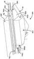
도 30 내지 도 32는 본원에서 개시된 부착 구조물 내로 통합될 수 있는 크림프(216)의 다른 실시예를 도시한다. 특히, 도 30은 크림프(216)의 상단 등각도를 도시하고; 도 31은 크림프(216)의 평면도를 도시하고; 도 32는 크림프(16)의 도 31의 A-A 축을 따른 단면도를 도시한다.30-32 illustrate another embodiment of a
본원에 도시된 크림프와 유사하게, 크림프(216)는 위에 도시된 지지 부재(12) 및/또는 이동 부재(14)의 부착 구조물 내로 통합될 수 있다. 다양한 실시예에 따르면, 크림프(216)는 지지 부재(12) 내에 통합될 수 있고 기저부 층(16)과 단일체형일 수 있다. 추가적으로 또는 대안적으로, 크림프(216)는 이동 부재(14) 내에 통합될 수 있고 판(60)과 단일체형일 수 있다. Similar to the crimp shown herein, the
크림프(216)는 함께 접히도록 구성된 제1 및 제2 부분(218, 220)을 포함한다. 도시된 바와 같이, 제1 및 제2 부분(218, 220)이 함께 접힐 때, 이들은 SMA 와이어(15)를 크림핑하고 SMA(15)를 제 위치에서 유지할 수 있다. 도시된 바와 같이, 제1 및 제2 부분(218, 220)은 재료의 단일체형 단편이다. 그러나, 실시예에서, 제1 및 제2 부분(218, 220)은 비-단일체형일 수 있고, 접착제, 용접, 납땝 접합부 및/또는 기타를 이용하여 함께 결합될 수 있다.The
다양한 실시예에 따르면, 크림프(216)는 크림프(216)의 적어도 하나의 측면(216a, 216b)으로부터 연장되고 SMA 와이어(15) 상에 크림핑력을 지지 및/또는 제공하는 변형 완화 부재(192)를 포함할 수 있다. 다양한 실시예에 따르면, 변형 완화 부재(192)는 크림프(216)의 양 측면(216a, 216b)으로부터 연장될 수 있다. 이들 실시예에서, 변형 완화 부재(192)는 도시된 바와 같이 크림프(216)의 측면(216a, 216b)으로부터 상이한 거리로 연장될 수 있다. 대안적으로, 변형 완화 부재(192)가 크림프(216)에 포함되지 않을 수 있다.According to various embodiments, the
다양한 실시예에 따르면, 접착제(222)가 크림프(216)의 제1 및 제2 부분(218, 220) 사이에 배치될 수 있다. 이들 실시예 중 일부에 따르면, 접착제(222)는 단지 제1 및 제2 부분(218, 220)의 일부 사이에 배치될 수 있다. 변형 완화 부재(192)를 포함하는 다양한 실시예에 따르면, 접착제(222)는 변형 완화 부재(192)의 제1 및 제2 부분(192a, 192b) 사이에 배치될 수 있다. 그러나, 이들 실시예 중 일부에 따르면, 접착제(222)는 단지 제1 및 제2 부분(192a, 192b)의 일부 사이에 배치될 수 있다. 부가적으로 또는 대안적으로, 실시예에서, 접착제(222)는 크림프(216)의 적어도 하나의 측면(216a, 216b) 및/또는 변형 완화 부재(192)의 적어도 하나의 측면(192c, 192d)으로부터 연장될 수 있다(예를 들어, 그로부터 돌출될 수 있다). 예를 들어, 접착제(222)가 제1 및 제2 부분(192a, 192b) 사이에 배치될 때, 접착제(222)의 일부가 SMA(15)를 따라 위킹(wick)할 수 있고 크림프(216)의 측면(216a)을 넘어서 및/또는 변형 완화 부재(192)의 측면(192c)을 넘어서 연장될 수 있다.According to various embodiments, an adhesive 222 may be disposed between the first and
다양한 실시예에 따르면, 크림프(216)의 제1 및 제2 부분(218, 220) 사이에 및/또는 변형 완화 부재(192)의 제1 및 제2 부분(192a, 192b) 사이에 접착제(222)를 배치하기 위해, 크림프의 제1 및 제2 부분(218, 220)은 함께 크림핑될 수 있고 접착제(222)는 크림프(216)의 측면(216a, 216b)에 도포될 수 있다. 다양한 실시예에 따르면, 접착제(222)는 변형 완화 부재(192)가 연장되지 않는 크림프(216)의 측면(216a, 216b) 또는 변형 완화 부재(192)가 크림프(216)의 측면(216a, 216b)으로부터 더 작은 거리로 연장되는 크림프(216)의 측면(216a, 216b)에 도포될 수 있다. 예를 들어, 변형 완화 부재(192)는 크림프(216)의 측면(216a)에 비해 크림프(216)의 측면(216b)으로부터 더 작은 거리로 연장된다. 그에 따라, 접착제(222)는 크림프(216)의 측면(216b)에 도포될 수 있다. 다양한 실시예에 따르면, 접착제(222)는 SMA 와이어(15) 상에서 변형 완화 부재(192)의 측면(192c, 192d)으로부터 50 미크론 및/또는 변형 완화 부재(192)의 내부 상에서 변형 완화 부재(192)의 측면(192c, 192d)으로부터 100 미크론 이내에 도포될 수 있다. 접착제(222)를 경화시킨 후에, 접착제는 크림프(216)의 연부(216a)로부터 100 내지 250 미크론에 위치될 수 있다.According to various embodiments, an adhesive 222 may be provided between the first and
다양한 실시예에 따르면, 접착제(222)가 제1 및 제2 부분(218, 220) 사이에서 그리고 제1 측면(216a, 216b)에 대향하는 크림프(216)의 제2 측면(216a, 216b)(예를 들어, 측면(216a)) 밖으로 연장되도록 크림프의 제1 측면(216a, 216b)(예를 들어, 측면(216b))에 충분한 접착제(222)가 도포될 수 있다. 다양한 실시예에 따르면, 접착제(222)는 또한, 접착제(222)가 크림프(216)의 제2 측면(216a, 216b)을 지나 연장되고 제2 측면(216a, 216b)으로부터 돌출하는 변형 완화 부재(192) 내로 연장되도록 도포될 수 있다. 부가적으로 또는 대안적으로, 접착제(222)는, 도 32에 도시된 바와 같이, SMA 와이어(15)를 따라 위킹될 수 있고, 이는 접착제(222)가 변형 완화 요소(119)의 측면(192c, 192d)(예를 들어, 측면(192c))을 지나 연장되고 및/또는 SMA 와이어(15)를 따라 테이퍼지게 할 수 있다. 예를 들어, 접착제(222)는 변형 완화 부재(192)의 측면(192c, 192d)을 지나 대략 10 내지 50 미크론만큼 연장될 수 있다. 접착제(222)의 테이퍼는, 이하에서 설명되는 바와 같이, 현가 조립체(10)가 사용 중일 때, SMA 와이어(15) 상의 변형을 감소시킬 수 있다.According to various embodiments, an adhesive 222 is applied between the first and
다양한 실시예에 따르면, 접착제(222)는 크림프(216)의 측면(216a, 216b)에 근접 및/또는 인접하는 SMA 와이어(15)의 부분(15c, 15d) 상에 배치될 수 있다. 예를 들어, 접착제(222)는 크림프(216)의 측면(216a)에 근접 및/또는 인접하는 SMA 와이어(15)의 부분(15c) 상에 배치될 수 있다. 다양한 실시예에 따르면, 부분(15c, 15d)은 또한 변형 완화 부재(192)의 측면(192c, 192d)에 근접 및/또는 인접할 수 있다. 예를 들어, 부분(15c)은 변형 완화 부재(192)의 측면(192c)에 근접 및/또는 인접할 수 있다. 접착제(222)가 크림프(216)의 측면(216a, 216b)에 근접 및/또는 인접하고 및/또는 변형 완화 부재(192)에 근접 및/또는 인접하는 다양한 실시예에 따르면, 접착제(222)는 또한 제1 및 제2 부분(218, 220) 사이에 배치되고 및/또는 제1 및 제2 부분(192a, 192b) 사이에 배치될 수 있다.The adhesive 222 may be disposed on the
다양한 실시예에 따르면, 접착제(222)는 SMA 와이어(15)의 부분(15c)이 크림프(216)의 측면(216a)으로부터 빠져나오고 및/또는 변형 완화 부재(192)의 측면(192c)으로부터 빠져나오는 각도를 제어하도록 도포 및/또는 경화될 수 있다. 예를 들어, 이동 부재(14)를 지지 부재(12)에 대해서 작동시키기 위해서, 제어 신호가 SMA 와이어(15)에 인가될 수 있다. 이후, 접착제(222)는 크림프의 측면(216a) 및 변형 완화 부재(192)의 측면(192c)을 빠져나오는 SMA 와이어(15)의 부분(15c)의 출사각이 대략 0 도가 되도록 도포 및/또는 경화될 수 있다. According to various embodiments, the adhesive 222 may be used to prevent the
다른 예에서, 고정구(340)는, 도 34에 도시된 것과 같은 실시예에 따르면, 본원에서 설명된 것들을 포함하는 유형의 지지 부재(12) 및 이동 부재(14) 모두를 포함하는 현가 조립체(10)를 수용하도록 구성된다. 고정구(340)는 SMA 와이어(15)를 수용하도록 구성된 와이어 정지 핀(342)을 포함한다. 와이어 정지 핀(342)은, 이에 한정되는 것은 아니지만, 현가 조립체에 대한 와이어의 위치를 수용하고 유지하도록 구성된 로드, 후크, 또는 다른 구조물을 포함하는 SMA 와이어(15)를 수용 및 유지하기 위해 고정구(340)에 부착된 임의의 구조물일 수 있다.In another example,
실시예에 따르면, 고정구(340)는, 와이어 정지 핀(342)이 SMA 와이어(15)를 측면(216a) 또는 크림프의 변형 완화 부재의 측면(192c)에 수직인 축으로부터 측정되는, SMA 와이어(15)의 부분(15c)이 크림프(216)의 측면(216a)으로부터 빠져나오고 및/또는 변형 완화 부재(192)의 측면(192c)으로부터 빠져나오는 각도 - 본원에서는 출사각(344, 346)이라 지칭됨 - 로 유지시키도록, SMA 와이어(15)를 갖는 현가 조립체를 수용하도록 구성된다. 이러한 실시예에 대해, 접착제(222)는 본원에 설명된 것들을 포함하는 기술을 이용하여 경화된다. 특정 예는 고정구(340)에 장착된 현가 조립체의 적어도 미경화 접착제 및 SMA 와이어(15)를 가열하는 것을 포함한다. 가열은 접착제를 경화시키고, SMA 와이어(15)가 전기 신호의 사용 없이 경화 열로 인해 수축하여 똑바로 나아감에 따라 출사각(344, 346)을 설정하도록 SMA 와이어(15)를 활성화시킨다. 따라서, 출사각(344, 346)으로 SMA 와이어(15)를 유지하기 위해 사용되는 와이어 정지 핀(342)을 갖는 고정구(340)는 하나 이상의 SMA 와이어(15)에 제어 신호를 인가할 필요 없이 출사각을 설정하는 능력을 제공한다. 특정 예는, SMA 와이어(15)가 지지 부재(12) 상의 크림프로부터 5 도의 출사각(344)을 갖고 이동 부재(14) 상의 크림프로부터 6 도의 출사각(346)을 갖도록, 현가 조립체의 SMA 와이어(15)를 유지하기 위해 와이어 정지 핀(342)을 갖는 고정구(340)를 사용하는 것을 포함한다. 다양한 실시예에 따른 와이어 정지 핀(342)을 갖는 고정구(340)는 하나 이상의 크림프로부터의 임의의 출사각으로 SMA 와이어(15)를 유지하도록 구성될 수 있고, 하나 초과의 크림프로부터의 출사각(344, 346)은 등가일 수 있다.According to an embodiment, the
통상적인 실시예에서, (도 1a 내지 도 1b의) 현가 조립체(10)가 응력 하에 있을 때, SMA 와이어(15)가 크림프(216)의 측면(216a)을 빠져나가는 곳에 근접하여, SMA 와이어(15)가 손상 및/또는 파괴될 수 있다. 이유는 크림프(216)의 측면(216a)이 SMA 와이어(15)에 대한 고유의 높은 응력 영역이기 때문이다. 다양한 실시예에 따르면, 접착제(222)는 SMA 와이어(15) 상의 응력을 감소시킬 수 있다. 예를 들어, 크림프(216)의 제1 및 제2 부분(218, 220) 사이에 배치된 접착제(222)를 이용함으로써, 접착제(222)가 SMA 와이어(15)를 제 위치에서 유지하는데 도움이 되기 때문에, 크림프(216)를 폐쇄하기 위해서 적은 기계적 힘이 이용될 수 있다. 크림프(216)를 폐쇄하기 위한 적은 기계적 힘을 이용함으로써, 제1 및 제2 부분(218, 220) 사이에 배치된 SMA 와이어(15)의 부분에 적은 손상 및/또는 적은 단락 위험이 발생될 수 있다. 추가적으로 또는 대안적으로, 크림프(216)의 측면(216a)에 근접한 SMA 와이어(15)의 부분(15c)에 더 적은 손상 및/또는 단락 위험이 발생할 수 있다. 단락 위험은 크림프(218)를 크림핑할 때 너무 많은 기계적 힘을 인가할 때 기저부 층(16)으로부터 SMA 와이어(15)를 절연하는 유전체 층(예를 들어, 도 15a 내지 도 15b의 유전체 층(100))을 파괴하는 것으로부터 발생할 수 있다.In a typical embodiment, when the suspension assembly 10 (of FIGS. 1A-1B) is under stress, the
다른 예로서, 접착제(222)는 크림프(216)의 측면(216a, 216b) 및/또는 변형 완화 부재(192)의 측면(192c, 192d)으로부터 연장될 수 있다. 예를 들어, 접착제는 크림프(216)의 측면(216a) 및/또는 변형 완화 부재(192)의 측면(192c)으로부터 연장될 수 있다. 접착제(222)는 크림프(216) 및/또는 변형 완화 부재(192)보다 낮은 강성을 갖기 때문에, 접착제(222)는 굽힘 응력이 달리 분산될 수 있는 것보다, 크림프(216)의 측면(216a, 216b) 부근에서 및/또는 변형 완화 부재(192)의 측면(192c, 192d) 부근에서 발생하는 임의의 굽힘 응력을 SMA(15)의 더 큰 부분에 걸쳐 분산시키는 것을 도울 수 있다. 즉, 접착제(222)는 크림프(216) 및/또는 변형 완화 부재(192)보다 낮은 강성을 갖기 때문에, 접착제(222)는 크림프(216) 또는 변형 완화 부재(192) 중 하나보다 SMA 와이어(15)와 더 굽혀질 수 있고, 그에 의해 현가 조립체(10)(도 1의)가 응력 하에 있을 때 SMA 와이어(15)의 굽힘 반경을 증가시킨다. 예를 들어, 각도(θ)로 굽혀지는 폭(x)을 가지는 SMA 와이어(15)의 섹션 대신에, 접착제(222)는 각도(θ)로 굽혀지는 섹션의 폭을 예를 들어, 2x, 3x, 4x, 등으로 증가시킬 수 있다. 이는 SMA 와이어(15) 상의 응력을 SMA 와이어(15)의 더 큰 부분에 걸쳐 분산시킨다. 다양한 실시예에 따르면, 접착제(222)가 크림프(216)의 측면(216a, 216b) 및/또는 변형 완화 부재(192)의 측면(192c, 192d)으로부터 돌출하는 거리는, 예를 들어 접착제(222)의 종류, 강성, 두께 및/또는 접착제(222)가 어떻게 도포되는지에 따라 달라질 수 있다.As another example, the adhesive 222 may extend from the
다양한 실시예에 따르면, 접착제(222)는 전도성 또는 비전도성일 수 있다. 예를 들어, 접착제는 시아노아크릴레이트로 구성될 수 있다. 전도성 접착제(222)가 사용되는 다양한 실시예에 따르면, 접착제(222)가 지지 부재(12)의 금속 기저부 층(16)에 단락되는 경우에 (도 1의) 현가 조립체(10)의 동작이 영향을 받을 수 있기 때문에, 접착제(222)는 지지 부재(12) 내로 통합된 크림프에 도포되지 않을 수 있다.According to various embodiments, the adhesive 222 may be conductive or non-conductive. For example, the adhesive may comprise cyanoacrylate. According to various embodiments in which the
다양한 실시예에 따르면, 접착제(222)는 열, 자외선, 접착제(222)를 둘러싸는 가스에 유지되는 습도 레벨, 화학적 첨가제 및/또는 기타 중 하나 이상을 이용하여 경화될 수 있다. 경화 메커니즘으로서 열을 이용하는 다양한 실시예에 따르면, 전체 크림프(216) 및/또는 크림프(216)가 통합되는 구조물이 가열될 수 있다. 다양한 실시예에 따르면, 접착제(222)가 경화되기 전에, 부분(15c)이 크림프(216)의 측면(216a)을 빠져나가고 및/또는 변형 완화 부재(192)의 측면(192c)을 빠져나가는 각도를 제어하도록 지지 부재(12)에 대해 이동 부재(14)를 작동시키기 위해, 제어 신호가 SMA 와이어(15)에 송신될 수 있다.According to various embodiments, the adhesive 222 may be cured using one or more of heat, ultraviolet light, humidity levels maintained in the gas surrounding the adhesive 222, chemical additives, and / or the like. According to various embodiments utilizing heat as a curing mechanism, the structure in which the
다양한 실시예에 따르면, 접착제(222)는 접착제의 영률에 기초하여 선택될 수 있다. 예를 들어, 20 메가파스칼 내지 2000 메가파스칼의 영률을 갖는 접착제가 접착제(222)로서 선택될 수 있다. 추가적으로 또는 대안적으로, 접착제(222)는 접착제의 파괴까지의 변형 연신 비율에 기초하여 선택될 수 있다. 예컨대, 100% 내지 300%의 파괴까지의 변형 연신율을 갖는 접착제가 접착제(222)로서 선택될 수 있다. 다른 예로서, 2% 내지 4%의 파괴까지의 변형 연신율을 갖는 접착제가 접착제(222)로서 선택될 수 있다.According to various embodiments, the adhesive 222 may be selected based on the Young's modulus of the adhesive. For example, an adhesive having a Young's modulus of 20 megapascals to 2000 megapascals may be selected as the adhesive 222. Additionally or alternatively, the adhesive 222 can be selected based on the strain elongation to fracture of the adhesive. For example, an adhesive having a strain elongation up to failure of 100% to 300% may be selected as the adhesive 222. As another example, an adhesive having a strain elongation up to failure of 2% to 4% may be selected as the adhesive 222.
다양한 실시예에 따르면, 하나 초과의 접착제가 접착제(222)로서 사용될 수 있다. 예를 들어, 제1 접착제가 크림프(216)의 연부(216a)에 근접 및/또는 인접하여 그리고/또는 응력 완화 부재(192)의 측면(192c)에 근접 및/또는 인접하여 배치될 수 있고; 제2 접착제가 제1 및 제2 부분(218, 220) 사이 및/또는 제1 및 제2 부분(192a, 192b) 사이에 배치될 수 있다. 다양한 실시예에 따르면, 제1 접착제는 제2 접착제가 제1 및 제2 부분(216a, 216b) 사이 및/또는 제1 및 제2 부분(192a, 192b) 사이에 배치되기 전에 또는 후에 경화될 수 있다. 다양한 실시예에 따르면, 제1 접착제가 경화되기 전 또는 후에, 접착제(222)의 제2 접착제는 제1 및 제2 부분(216a, 216b) 사이 및/또는 제1 및 제2 부분(192a, 192b) 사이에 배치되고 경화될 수 있다. 다양한 실시예에 따르면, 접착제(222)의 제1 접착제는 SMA 와이어(15)를 따라 위킹될 수 있다. 부가적으로, 제2 접착제가 도포되기 전에 접착제(222)의 제1 접착제를 경화시키는 것 또는 제2 접착제(예를 들어, 대략 50 센티포아즈의 점도를 가짐)보다 높은 점도를 갖는(예를 들어, 대략 50,000 센티포아즈의 점도를 갖는) 제1 접착제를 사용하는 것에 의해, 제1 접착제는 제2 접착제가 SMA 와이어(15)를 위킹하는 것을 차단할 수 있다. 그에 따라, 접착제(222)의 제1 접착제가 제2 접착제(예를 들어, 1500 메가파스칼보다 더 큰)보다 낮은 탄성률(예를 들어, 1500 메가파스칼 미만)을 갖는 경우, 접착제(222)를 만드는 접착제의 조합은 현가 조립체(10)가 사용 중일 때 SMA 와이어(15) 상의 응력을 감소시킬 수 있다.According to various embodiments, more than one adhesive may be used as the adhesive 222. For example, a first adhesive may be disposed proximate and / or adjacent the
도 33은 부착 구조물(224)의 다른 실시예를 도시한다. 다양한 실시예에 따르면, 부착 구조물(224)은 지지 부재(12) 및/또는 이동 부재(14)의 하나 이상의 대각선 방향 모서리 내로 통합된다. 예를 들어, 부착 구조물(224)은 지지 부재(12)의 2개의 대각선 방향 모서리 및/또는 이동 부재(14)의 2개의 대각선 내로 통합될 수 있다. 또한, 부착 구조물(224)은 하나 이상의 크림프(226a, 226b)를 이용하여 SMA 와이어(15a 및 15b)와 같은 하나 이상의 SMA 와이어(15)를 크림핑하도록 구성된다.33 shows another embodiment of the
도 33에 도시된 실시예에 따르면, 부착 구조물(224)은 기저부 층(16)과 단일체형이고, 2개의 크림프(226a, 226b)를 포함한다. 2개의 크림프(226a, 226b)는 (도 2a 및 도 2b의) 주요 평면형 표면 부분(26)으로부터 (예를 들어, z-방향으로) 이격된 레벨에서 기저부 층(16) 내의 턱부(25) 상에 형성된다. 도시된 바와 같이, 각각의 크림프(226a, 226b)는 제1 부분(228a, 228b) 및 제2 부분(230a, 230b)을 포함한다. 제1 부분(228a, 228b)은 각각 제1 부분(228a, 228b) 및 제2 부분(230a, 230b)을 함께 크림핑하기 위해서 각각의 축(232a, 232b)을 따라서 실질적으로 접히도록 구성된다. 일단 함께 크림핑되면, 제1 부분(228a, 228b) 및 제2 부분(230a, 230b)은 SMA 와이어(15a, 15b)를 제 위치에 유지한다. 도 1a 및 도 1b에서 앞서서 도시된 바와 같이, SMA 와이어(15)의 다른 단부는 이동 부재(14)에 결합된다.According to the embodiment shown in Figure 33, the
다양한 실시예에 따르면, 제1 부분(228a, 228b) 및 제2 부분(230a, 230b)은 재료의 단일체형 단편일 수 있다. 그러나, 실시예에서, 제1 부분(228a, 228b) 및 제2 부분(230a, 230b)은 비-단일체형일 수 있고, 접착제, 용접, 납땜 접합부 및/또는 기타를 이용하여 함께 결합될 수 있다.According to various embodiments, the
다양한 실시예에 따라서, 제1 및 제2 크림프(226a, 226b)는 부착 구조물(224)의 크림프(226a, 226b)의 적어도 하나의 측면으로부터 연장되는 플랫폼(234a, 234b)을 포함할 수 있다. 다양한 실시예에 따르면, 플랫폼(236a, 236b)은 제2 부분(230a, 230b)과 단일체형일 수 있다. 예를 들어, 제1 부분(228a, 228b)의 일부가 제거되어 제2 부분(230a, 230b)의 상부 부분을 노출시킬 수 있다. 대안적으로, 플랫폼(236a, 236b)은 제2 부분(230a, 230b)과 비-단일체형일 수 있다. 예를 들어, 플랫폼(236a, 236b)은 변형 완화 부재의 저부 부분(예를 들어, 도 30 내지 도 32에 도시된 변형 완화 부재(192)의 제2 부분(192b))일 수 있고, 상부 부분(예를 들어, 도 30 내지 도 32에 도시된 변형 완화 부재(192)의 제1 부분(192a))은 제거될 수 있다. 그러나, 이는 단지 예이며 제한적인 것을 의미하지 않는다.The first and
접착제(236a, 236b)가 플랫폼(234a, 234b)의 각각에 배치될 수 있다. 다양한 실시예에 따르면, 접착제(236a, 236b)는 SMA 와이어(15a, 15b)를 플랫폼(234a, 234b)에 결합시킬 수 있다. 전술한 접착제(222)와 유사하게, 접착제(236a, 236b)는, 큰 영역에 걸쳐 SMA 와이어(15a, 15b)의 굽힘을 분산시키는 것 또는 SMA 와이어(15a, 15b)가 크림프(226a, 226b)의 측면으로부터 더 멀리 굽혀지게 하는 것에 의해서, 크림프(226a, 226b)의 측면 근처의 SMA 와이어(15a, 15b) 상의 응력을 감소시킬 수 있다.
다양한 실시예에 따르면, 접착제(236a, 236b)는 도 30 내지 도 32와 관련하여 전술한 접착제(222)와 동일하거나 유사한 하나 이상의 특성을 가질 수 있다. 예를 들어, 접착제(236a, 236b)는 전도성 또는 비-전도성일 수 있다. 예를 들어, 접착제(236a, 236b)는 시아노아크릴레이트로 구성될 수 있다. 다양한 실시예에 따르면, 전도성 접착제가 접착제(236a, 236b)로서 이용될 때, 접착제(236a, 236b)가 지지 부재(12)의 금속 기저부 층(16)에 단락되는 경우에, 현가 조립체(10)의 동작이 영향을 받을 가능성이 더 클 수 있기 때문에, 접착제(236a, 236b)는 지지 부재(12) 내로 통합되는 크림프에 도포되지 않을 수 있다. 다양한 실시예에 따르면, 접착제(236a) 및 접착제(236b)를 위해 동일한 유형의 접착제가 사용될 수 있거나, 접착제(236a) 및 접착제(236b)를 위해 상이한 유형의 접착제가 사용될 수 있다.According to various embodiments, the
다양한 실시예에 따르면, 접착제(236a, 236b)는 열, 자외선, 접착제(236a, 236b)를 둘러싸는 가스로 유지되는 습도 레벨, 화학적 첨가제 및/또는 기타 중 하나 이상을 사용하여 경화될 수 있다. 경화 메커니즘으로서 열을 이용하는 다양한 실시예에 따르면, 크림프(226a, 226b) 및/또는 크림프(226a, 226b)가 통합되는 구조물이 가열될 수 있다. 다양한 실시예에 따르면, 접착제(236a, 236b)가 경화되기 전에, SMA 와이어(15a, 15b)가 크림프(226a, 226b)의 측면을 빠져나가고 및/또는 변형 완화 부재의 측면을 빠져나가는 각도를 제어하기 위해, 지지 부재(12)에 대해 이동 부재(14)를 작동시키도록, 제어 신호가 SMA 와이어(15a, 15b)에 송신될 수 있다.According to various embodiments, the
접착제(222)와 유사하게, 접착제(236a, 236b)는 접착제의 영률에 기초하여 선택될 수 있다. 예를 들어, 40 메가파스칼 내지 2000 메가파스칼의 영률을 갖는 접착제가 접착용 접착제(236a, 236b)로서 사용될 수 있다. 추가적으로 또는 대안적으로, 접착용 접착제(236a, 236b)는 접착제의 파괴까지의 변형 연신 비율에 기초하여 선택될 수 있다. 예를 들어, 100% 내지 300%의 파괴까지의 변형 연신율을 갖는 접착제가 접착제(236a, 236b)로서 사용될 수 있다. 다른 예로서, 2% 내지 4%의 파괴까지의 변형 연신율을 갖는 접착제가 접착제(236a, 236b)로서 선택될 수 있다.Similar to the adhesive 222, the
부가적으로 또는 대안적으로, 접착제(236a, 236b)는 대략 낮은 내지 중간 듀로미터 등급을 가질 수 있다. 예를 들어, 접착제(236a, 236b)는 90 미만의 쇼어 OO 듀로미터를 가질 수 있다. 그러나, 이는 단지 예이며 제한적인 것을 의미하지 않는다.Additionally or alternatively, the
다양한 실시예에 따르면, 부착 구조물(224)은 또한 도 30 내지 도 32에 도시된 접착제(222)와 동일하거나 유사한 접착제를 포함할 수 있다. 예를 들어, 접착제가 크림프(226a, 226b)의 제1 부분(228a, 228b)과 제2 부분(230a, 230b) 사이에 배치될 수 있고 및/또는 크림프(226a, 226b)의 하나 이상의 측면으로부터 연장될 수 있다. 추가적으로 또는 대안적으로, 변형 완화 부재(예를 들어, 변형 완화 부재(192))가 크림프(226a, 226b) 내에 통합될 때, 접착제는 변형 완화 부재의 제1 및 제2 부분(예를 들어, 부분(192a, 192b)) 사이에 배치될 수 있고 및/또는 변형 완화 부재의 측면(예를 들어, 측면(192c))으로부터 연장될 수 있다. 접착제(236a, 236b)가 경화되기 전 또는 후에, 접착제(예를 들어, 접착제(222))는 제1 부분(228a, 228b)과 제2 부분(230a, 230b) 사이에 배치될 수 있다. 접착제(예를 들어, 접착제(222))가 제1 부분(228a, 228b)과 제2 부분(230a, 230b) 사이에 및/또는 변형 완화 부재의 제1 및 제2 부분 사이에 배치된 후에, 접착제는 접착제(236a, 236b)를 경화시키는 것과 동시에 또는 그에 후속하여 경화될 수 있다.According to various embodiments, the
개시내용의 실시예가 바람직한 실시예를 참조하여 설명되었지만, 통상의 기술자는 개시내용의 사상 및 범위 내에서 형태 및 상세부분에 대한 변화가 이루어질 수 있다는 것을 이해할 수 있을 것이다. 예를 들어, 예시된 실시예는 지지 부재에 대향하는 굴곡부 아암의 측면 상에(즉, 굴곡부 아암의 상단부 측면 상에) 트레이스를 포함하지만, 다른 실시예는 대안적으로 또는 부가적으로 정적 부재에 대면하는 굴곡부 아암의 측면 상에(즉, 굴곡부 아암의 하단부 측면 상에) 트레이스를 포함할 수 있다. 이동 부재의 하단부 측면 상에 있는 트레이스에 추가하여, 와이어 부착 구조물은 도면에 도시된 바와 같이 정적 부재로부터 멀어지는 대신에 정적 부재를 향할 수 있다(예를 들어, 제1 부분, 116 또는 도 19는 도시된 바와 같이 상단부 측면 상에 있는 대신에 와이어 부착 구조물의 하단부 측면 상에 배향될 수 있다).Although the embodiments of the disclosure have been described with reference to the preferred embodiments, those skilled in the art will understand that changes may be made in form and detail within the spirit and scope of the disclosure. For example, although the illustrated embodiment includes traces on the sides of the flexion arms (i.e., on the upper side of the flexion arms) opposite the support members, other embodiments may alternatively or additionally include traces on the static member (I.e., on the lower end side of the bend arm) on the side of the facing bend arm. In addition to the traces on the lower end side of the movable member, the wire attachment structure may face the static member instead of moving away from the static member as shown in the figure (e.g., first portion, 116 or 19, Can be oriented on the lower end side of the wire attachment structure instead of being on the top side as shown.
Claims (50)
하나 이상의 제1 와이어 부착 구조물을 포함하는 지지 부재;
하나 이상의 제2 와이어 부착 구조물을 포함하는 이동 부재;
상기 하나 이상의 제1 와이어 부착 구조물 및 상기 하나 이상의 제2 와이어 부착 구조물의 적어도 하나의 부분들 사이에 배치되는 접착제; 및
상기 하나 이상의 제1 와이어 부착 구조물과 상기 하나 이상의 제2 와이어 부착 구조물 사이에서 연장되는 형상기억합금 와이어로서, 상기 형상기억합금 와이어는 하나 이상의 제1 와이어 부착 구조물, 하나 이상의 제2 와이어 부착 구조물 및 접착제에 결합되는, 형상기억합금 와이어를 포함하는 현가 조립체.Suspension assembly,
A support member comprising at least one first wire attachment structure;
A movable member including at least one second wire attachment structure;
An adhesive disposed between at least one of the at least one first wire attachment structure and the at least one second wire attachment structure; And
A shape memory alloy wire extending between the at least one first wire attachment structure and the at least one second wire attachment structure, the shape memory alloy wire comprising at least one first wire attachment structure, at least one second wire attachment structure, Wherein the shape memory alloy wire is coupled to the wire.
하나 이상의 제1 와이어 부착 구조물을 포함하는 지지 부재;
하나 이상의 제2 와이어 부착 구조물을 포함하는 이동 부재;
상기 하나 이상의 제1 와이어 부착 구조물 및 상기 하나 이상의 제2 와이어 부착 구조물 사이에서 연장되고 이들에 결합되는 형상기억합금 와이어; 및
상기 하나 이상의 제1 와이어 부착 구조물 및 상기 하나 이상의 제2 와이어 부착 구조물 중 적어도 하나의 측면에 근접하는 상기 형상기억합금 와이어의 일부 상에 배치된 접착제를 포함하는 현가 조립체.Suspension assembly,
A support member comprising at least one first wire attachment structure;
A movable member including at least one second wire attachment structure;
A shape memory alloy wire extending between and being coupled between the at least one first wire attachment structure and the at least one second wire attachment structure; And
And an adhesive disposed on a portion of the shape memory alloy wire proximate to at least one side of the at least one first wire attachment structure and the at least one second wire attachment structure.
하나 이상의 제1 와이어 부착 구조물을 포함하는 지지 부재;
하나 이상의 제2 와이어 부착 구조물을 포함하는 이동 부재;
상기 하나 이상의 제1 와이어 부착 구조물 및 상기 하나 이상의 제2 와이어 부착 구조물의 적어도 하나의 측면으로부터 연장되는 플랫폼 부분;
상기 플랫폼 부분 상에 배치된 접착제; 및
상기 하나 이상의 제1 와이어 부착 구조물과 상기 하나 이상의 제2 와이어 부착 구조물 사이에서 연장되고, 상기 하나 이상의 제1 와이어 부착 구조물, 상기 하나 이상의 제2 와이어 부착 구조물 및 상기 접착제에 결합되는 형상기억합금 와이어를 포함하는 현가 조립체.Suspension assembly,
A support member comprising at least one first wire attachment structure;
A movable member including at least one second wire attachment structure;
A platform portion extending from at least one side of the at least one first wire attachment structure and the at least one second wire attachment structure;
An adhesive disposed on the platform portion; And
A shape memory alloy wire extending between the at least one first wire attachment structure and the at least one second wire attachment structure, the shape memory alloy wire coupled to the at least one first wire attachment structure, the at least one second wire attachment structure, Comprising a suspension assembly.
상기 현가 조립체를 수용하는 단계로서, 상기 현가 조립체는,
하나 이상의 제1 와이어 부착 구조물을 포함하는 지지 부재;
하나 이상의 제2 와이어 부착 구조물을 포함하는 이동 부재; 및
상기 하나 이상의 제1 와이어 부착 구조물과 상기 하나 이상의 제2 와이어 부착 구조물에 결합되고 이들 사이에서 연장되는 형상기억합금 와이어를 포함하는,
수용 단계;
상기 하나 이상의 제1 와이어 부착 구조물 및 상기 하나 이상의 제2 와이어 부착 구조물 중 적어도 하나의 측면에 근접하게 접착제를 배치하는 단계;
상기 형상기억합금 와이어를 상기 하나 이상의 제1 와이어 부착 구조물 중 적어도 하나에 대해 소정의 출사각으로 유지하는 단계; 및
상기 접착제를 경화시키는 단계를 포함하는 방법.A method of making a suspension assembly comprising an adhesive, the method comprising:
Receiving the suspension assembly, the suspension assembly comprising:
A support member comprising at least one first wire attachment structure;
A movable member including at least one second wire attachment structure; And
And a shape memory alloy wire coupled to and extending between the at least one first wire attachment structure and the at least one second wire attachment structure.
Acceptance phase;
Disposing an adhesive in proximity to at least one side of the at least one first wire attachment structure and the at least one second wire attachment structure;
Maintaining the shape memory alloy wire at a predetermined exit angle relative to at least one of the one or more first wire attachment structures; And
And curing the adhesive.
상기 현가 조립체를 수용하는 단계로서, 상기 현가 조립체는,
하나 이상의 제1 와이어 부착 구조물을 포함하는 지지 부재;
하나 이상의 제2 와이어 부착 구조물을 포함하는 이동 부재;
상기 하나 이상의 제1 와이어 부착 구조물 및 상기 하나 이상의 제2 와이어 부착 구조물 중 적어도 하나의 부분들 사이에 배치되는 미경화 접착제; 및
상기 하나 이상의 제1 와이어 부착 구조물과 상기 하나 이상의 제2 와이어 부착 구조물 사이에서 연장되고 이들에 결합되는 형상기억합금 와이어를 포함하는,
수용 단계;
상기 형상기억합금 와이어를 상기 하나 이상의 제1 와이어 부착 구조물 중 적어도 하나에 대해 소정의 출사각으로 유지하는 단계; 및
상기 접착제를 경화시키는 단계를 포함하는 방법.A method of making a suspension assembly comprising an adhesive, the method comprising:
Receiving the suspension assembly, the suspension assembly comprising:
A support member comprising at least one first wire attachment structure;
A movable member including at least one second wire attachment structure;
An uncured adhesive disposed between at least one of the at least one first wire attachment structure and the at least one second wire attachment structure; And
And a shape memory alloy wire extending between and joined to the at least one first wire attachment structure and the at least one second wire attachment structure.
Acceptance phase;
Maintaining the shape memory alloy wire at a predetermined exit angle relative to at least one of the one or more first wire attachment structures; And
And curing the adhesive.
상기 현가 조립체를 수용하는 단계로서, 상기 현가 조립체는,
하나 이상의 제1 와이어 부착 구조물을 포함하는 지지 부재;
하나 이상의 제2 와이어 부착 구조물을 포함하는 이동 부재;
상기 하나 이상의 제1 와이어 부착 구조물 및 상기 하나 이상의 제2 와이어 부착 구조물 중 적어도 하나의 부분들 사이에 배치되는 제1 미경화 접착제;
상기 하나 이상의 제1 와이어 부착 구조물 및 상기 하나 이상의 제2 와이어 부착 구조물 중 적어도 하나에 근접하여 배치되는 제2 미경화 접착제; 및
상기 하나 이상의 제1 와이어 부착 구조물과 상기 하나 이상의 제2 와이어 부착 구조물 사이에서 연장되고 이들에 결합되는 형상기억합금 와이어를 포함하는,
수용 단계,
상기 제2 미경화 접착제를 경화시키는 단계; 및
상기 제1 미경화 접착제를 경화시키는 단계를 포함하는 방법.A method of making a suspension assembly comprising an adhesive, the method comprising:
Receiving the suspension assembly, the suspension assembly comprising:
A support member comprising at least one first wire attachment structure;
A movable member including at least one second wire attachment structure;
A first uncured adhesive disposed between portions of at least one of the at least one first wire attachment structure and the at least one second wire attachment structure;
A second uncured adhesive disposed adjacent to at least one of the at least one first wire attachment structure and the at least one second wire attachment structure; And
And a shape memory alloy wire extending between and joined to the at least one first wire attachment structure and the at least one second wire attachment structure.
Acceptance phase,
Curing the second uncured adhesive; And
And curing the first uncured adhesive.
하나 이상의 와이어 부착 구조물을 포함하는 상기 현가 조립체를 수용하는 단계로서, 상기 하나 이상의 와이어 부착 구조물 중 적어도 하나는 상기 하나 이상의 와이어 부착 구조물 중 적어도 하나의 부분들 사이에 배치된 미경화 접착제, 및 상기 하나 이상의 와이어 부착 구조물에 결합된 형상기억합금 와이어를 포함하는, 수용 단계;
상기 형상기억합금 와이어를 와이어 정지 핀을 갖는 고정구를 사용하여 하나 이상의 와이어 부착 구조물 중 적어도 하나에 대해 소정의 출사각으로 유지하는 단계; 및
적어도 미경화 접착제 및 형상기억합금 와이어를 가열하여 상기 접착제를 경화시키고 상기 출사각을 설정하는 단계를 포함하는 방법.A method of manufacturing a suspension assembly,
Comprising: receiving the suspension assembly including at least one wire attachment structure, wherein at least one of the one or more wire attachment structures comprises an uncured adhesive disposed between portions of at least one of the one or more wire attachment structures; A shape memory alloy wire coupled to the wire attachment structure;
Maintaining the shape memory alloy wire at a predetermined exit angle for at least one of the one or more wire attachment structures using a fixture having a wire stop pin; And
Heating at least the uncured adhesive and the shape memory alloy wire to cure the adhesive and set the exit angle.
Priority Applications (1)
| Application Number | Priority Date | Filing Date | Title |
|---|---|---|---|
| KR1020237028088A KR20230124776A (en) | 2016-06-09 | 2017-06-09 | Shape memory alloy wire attachment structures with adhesive for a suspension assembly |
Applications Claiming Priority (5)
| Application Number | Priority Date | Filing Date | Title |
|---|---|---|---|
| US201662348084P | 2016-06-09 | 2016-06-09 | |
| US62/348,084 | 2016-06-09 | ||
| PCT/US2017/036884 WO2017214583A1 (en) | 2016-06-09 | 2017-06-09 | Shape memory alloy wire attachment structures with adhesive for a suspension assembly |
| US15/618,917 | 2017-06-09 | ||
| US15/618,917 US11409070B2 (en) | 2016-06-09 | 2017-06-09 | Shape memory alloy wire attachment structures with adhesive for a suspension assembly |
Related Child Applications (1)
| Application Number | Title | Priority Date | Filing Date |
|---|---|---|---|
| KR1020237028088A Division KR20230124776A (en) | 2016-06-09 | 2017-06-09 | Shape memory alloy wire attachment structures with adhesive for a suspension assembly |
Publications (1)
| Publication Number | Publication Date |
|---|---|
| KR20190015528A true KR20190015528A (en) | 2019-02-13 |
Family
ID=60572600
Family Applications (2)
| Application Number | Title | Priority Date | Filing Date |
|---|---|---|---|
| KR1020197000337A KR20190015528A (en) | 2016-06-09 | 2017-06-09 | Shape memory alloy wire attachment structure having an adhesive for a suspension assembly |
| KR1020237028088A KR20230124776A (en) | 2016-06-09 | 2017-06-09 | Shape memory alloy wire attachment structures with adhesive for a suspension assembly |
Family Applications After (1)
| Application Number | Title | Priority Date | Filing Date |
|---|---|---|---|
| KR1020237028088A KR20230124776A (en) | 2016-06-09 | 2017-06-09 | Shape memory alloy wire attachment structures with adhesive for a suspension assembly |
Country Status (6)
| Country | Link |
|---|---|
| US (1) | US11409070B2 (en) |
| EP (1) | EP3468789A4 (en) |
| JP (2) | JP6923563B2 (en) |
| KR (2) | KR20190015528A (en) |
| CN (1) | CN109562592B (en) |
| WO (1) | WO2017214583A1 (en) |
Families Citing this family (22)
| Publication number | Priority date | Publication date | Assignee | Title |
|---|---|---|---|---|
| US9366879B1 (en) | 2014-12-02 | 2016-06-14 | Hutchinson Technology Incorporated | Camera lens suspension with polymer bearings |
| US9454016B1 (en) | 2015-03-06 | 2016-09-27 | Hutchinson Technology Incorporated | Camera lens suspension with integrated electrical leads |
| US11956544B2 (en) | 2016-03-11 | 2024-04-09 | Apple Inc. | Optical image stabilization with voice coil motor for moving image sensor |
| BR112018068282B1 (en) * | 2016-03-11 | 2022-11-29 | Apple Inc | CAMERA, CAMERA ACTUATOR AND MOBILE MULTIFUNCTIONAL DEVICE WITH OPTICAL IMAGE STABILIZATION BY VOICE COIL MOTOR TO MOVE IMAGE SENSOR |
| US10670878B2 (en) | 2016-05-19 | 2020-06-02 | Hutchinson Technology Incorporated | Camera lens suspensions |
| GB201717855D0 (en) * | 2017-10-30 | 2017-12-13 | Cambridge Mechatronics Ltd | SMA actuator bearings |
| GB2569036B (en) * | 2017-10-30 | 2020-06-17 | Cambridge Mechatronics Ltd | Assembly of shape memory alloy actuators |
| CN108247309B (en) * | 2017-12-20 | 2020-05-22 | 东莞市亚登电子有限公司 | Memory alloy wire mounting method for micro optical camera module |
| GB2570177A (en) * | 2018-01-11 | 2019-07-17 | Cambridge Mechatronics Ltd | Manufacture of shape memory alloy actuator assemblies |
| CN110784625B (en) * | 2018-07-25 | 2022-04-15 | 台湾东电化股份有限公司 | Driving mechanism of photosensitive assembly |
| GB2576362A (en) * | 2018-08-16 | 2020-02-19 | Cambridge Mechatronics Ltd | Improved crimping |
| CN109451226A (en) * | 2018-12-07 | 2019-03-08 | 河南省皓泽电子有限公司 | A kind of optical image vibration abatement |
| CN111405743B (en) * | 2019-01-03 | 2023-09-05 | 新科实业有限公司 | Suspension assembly of optical image stabilizer |
| CN110703404A (en) * | 2019-09-11 | 2020-01-17 | 瑞声科技(新加坡)有限公司 | Lens module |
| CN112631037B (en) * | 2019-09-21 | 2022-07-19 | 华为技术有限公司 | Anti-shake automatic focusing device and camera equipment |
| CN210958466U (en) * | 2019-11-12 | 2020-07-07 | 华为技术有限公司 | SMA actuator, image pickup apparatus, and electronic device |
| CN112946969B (en) * | 2019-11-25 | 2022-12-06 | 新思考电机有限公司 | Optical component drive device, camera device, and electronic apparatus |
| US20210165239A1 (en) * | 2019-12-03 | 2021-06-03 | New Shicoh Motor Co. Ltd. | Optical Member Driving Device, Camera Device and Electronic Apparatus |
| CN212211175U (en) * | 2020-06-23 | 2020-12-22 | 新思考电机有限公司 | OIS motor drive structure, OIS motor, camera device |
| JP2023179808A (en) * | 2020-11-02 | 2023-12-20 | アルプスアルパイン株式会社 | Lens drive device, camera module and method for manufacturing leans drive device |
| CN114035296B (en) * | 2021-04-28 | 2023-12-22 | 新思考电机有限公司 | Suspension mechanism for lens driving device, driving and image capturing device, and electronic apparatus |
| WO2023136306A1 (en) * | 2022-01-17 | 2023-07-20 | アルプスアルパイン株式会社 | Imaging device, camera module, and control method for imaging device |
Family Cites Families (97)
| Publication number | Priority date | Publication date | Assignee | Title |
|---|---|---|---|---|
| CH457131A (en) | 1967-09-06 | 1968-05-31 | Koch Carl | Photographic focusing screen camera |
| US3776447A (en) | 1969-06-30 | 1973-12-04 | Texas Instruments Inc | Automatic semiconductor bonding machine |
| US3734386A (en) | 1971-06-30 | 1973-05-22 | Ibm | Wiring apparatus with wire path forming means |
| US4140265A (en) | 1975-06-26 | 1979-02-20 | Kollmorgen Technologies Corporation | Method and apparatus for positioning the end of a conductive filament at a predetermined and repeatable geometric location for coupling to a predetermined terminal area of an element |
| JPS5698900A (en) | 1980-01-07 | 1981-08-08 | Hitachi Ltd | Device for automatically wiring printed circuit board |
| EP0203597B1 (en) | 1985-05-31 | 1990-07-11 | Emhart Industries, Inc. | Bonding head |
| US5743654A (en) | 1987-05-29 | 1998-04-28 | Kmc, Inc. | Hydrostatic and active control movable pad bearing |
| US4984581A (en) | 1988-10-12 | 1991-01-15 | Flexmedics Corporation | Flexible guide having two-way shape memory alloy |
| JPH05283146A (en) * | 1992-03-31 | 1993-10-29 | Toshiba Lighting & Technol Corp | Thick-film resistance heating element |
| US5269810A (en) * | 1992-06-19 | 1993-12-14 | W. L. Gore & Associates, Inc. | Patch electrode |
| JP2959322B2 (en) | 1993-03-09 | 1999-10-06 | 住友電装株式会社 | Harness electric wire manufacturing apparatus and manufacturing method |
| US5667884A (en) * | 1993-04-12 | 1997-09-16 | Bolger; Justin C. | Area bonding conductive adhesive preforms |
| US5831820A (en) | 1996-12-30 | 1998-11-03 | Huang; James | Peripheral docking module using a shape memory alloy actuator wire |
| US6149742A (en) | 1998-05-26 | 2000-11-21 | Lockheed Martin Corporation | Process for conditioning shape memory alloys |
| JP3488100B2 (en) | 1998-10-13 | 2004-01-19 | 矢崎総業株式会社 | Automatic cutting and crimping equipment |
| ATE344388T1 (en) | 1999-08-12 | 2006-11-15 | Perihelian Llc | DRIVE MADE OF A SHAPE MEMORY ALLOY AND CONTROL METHOD |
| US6639411B1 (en) * | 2000-09-05 | 2003-10-28 | Hutchinson Technology Incorporated | Microactuated suspension motor failure detection system |
| JP2002130114A (en) | 2000-10-20 | 2002-05-09 | Toshiba Corp | Actuator device |
| WO2002057627A1 (en) * | 2001-01-17 | 2002-07-25 | M 2 Medical A/S | Shape memory alloy actuator |
| JP4406707B2 (en) * | 2001-06-06 | 2010-02-03 | ソニー株式会社 | Two-axis device for optical disk device |
| JP4278364B2 (en) * | 2002-11-08 | 2009-06-10 | パイオニア株式会社 | Actuator for pickup device |
| US6916115B1 (en) | 2003-03-04 | 2005-07-12 | University Of Kentucky Research Foundation | System and device for characterizing shape memory alloy wires |
| US20080252769A1 (en) | 2004-02-06 | 2008-10-16 | Koninklijke Philips Electronic, N.V. | Camera Arrangement, Mobile Phone Comprising a Camera Arrangement, Method of Manufacturing a Camera Arrangement |
| JP2005227365A (en) * | 2004-02-10 | 2005-08-25 | Sony Corp | Method for manufacturing optical component |
| US7384531B1 (en) | 2004-02-19 | 2008-06-10 | Hutchinson Technology Incorporated | Plated ground features for integrated lead suspensions |
| JP2007537562A (en) | 2004-05-14 | 2007-12-20 | ハッチンソン テクノロジー インコーポレーティッド | Method for producing noble metal conductive lead for suspension assembly |
| US7679647B2 (en) | 2004-07-21 | 2010-03-16 | Hewlett-Packard Development Company, L.P. | Flexible suspension for image stabilization |
| WO2006016443A1 (en) * | 2004-08-12 | 2006-02-16 | Murata Manufacturing Co., Ltd. | Piezoelectric electro-acoustic transducer |
| JP4186907B2 (en) | 2004-10-14 | 2008-11-26 | ソニー株式会社 | Electronics |
| JP2007092556A (en) | 2005-09-27 | 2007-04-12 | Konica Minolta Opto Inc | Drive device and its manufacturing method |
| US7777782B2 (en) | 2005-11-04 | 2010-08-17 | Nokia Corporation | Stabilization of an image produced by optics |
| JP4737756B2 (en) * | 2006-02-27 | 2011-08-03 | Necトーキン株式会社 | Solid electrolytic capacitor |
| GB2451972B (en) | 2006-03-30 | 2010-06-30 | 1 Ltd | Camera lens actuation apparatus |
| GB0606425D0 (en) | 2006-03-30 | 2006-05-10 | 1 Ltd | Camera lens actuation apparatus |
| US8175449B2 (en) | 2006-05-30 | 2012-05-08 | Konica Minolta Opto, Inc. | Driving device, driving mechanism, and image sensing apparatus |
| US7650914B2 (en) | 2006-06-22 | 2010-01-26 | Autosplice, Inc. | Apparatus and methods for filament crimping and manufacturing |
| US7929252B1 (en) | 2006-10-10 | 2011-04-19 | Hutchinson Technology Incorporated | Multi-layer ground plane structures for integrated lead suspensions |
| US7832082B1 (en) | 2006-10-10 | 2010-11-16 | Hutchinson Technology Incorporated | Method for manufacturing an integrated lead suspension component |
| CA2676804A1 (en) | 2007-01-29 | 2008-08-07 | Spinal Modulation, Inc. | Sutureless lead retention features |
| WO2008099155A1 (en) | 2007-02-12 | 2008-08-21 | Cambridge Mechatronics Limited | Shape memory alloy actuation apparatus |
| GB0702676D0 (en) | 2007-02-12 | 2007-03-21 | 1 Ltd | Method of driving a shape memory alloy actuator |
| GB0702835D0 (en) | 2007-02-14 | 2007-03-28 | Johnson Electric Sa | Lens module |
| JP2008233526A (en) | 2007-03-20 | 2008-10-02 | Tamron Co Ltd | Actuator for preventing image shake and camera equipped therewith |
| EP2140138B1 (en) * | 2007-04-23 | 2012-04-11 | Cambridge Mechatronics Limited | Shape memory alloy actuation apparatus |
| US7974025B2 (en) | 2007-04-23 | 2011-07-05 | Cambridge Mechatronics Limited | Shape memory alloy actuation apparatus |
| JP5194622B2 (en) | 2007-08-02 | 2013-05-08 | コニカミノルタアドバンストレイヤー株式会社 | Drive mechanism, drive device, and lens drive device |
| CN101408655B (en) | 2007-10-11 | 2011-07-27 | 鸿富锦精密工业(深圳)有限公司 | Lens module |
| JP5101984B2 (en) | 2007-10-23 | 2012-12-19 | セイコーインスツル株式会社 | Drive module |
| KR20090081855A (en) * | 2008-01-25 | 2009-07-29 | 이-핀 옵티칼 인더스트리 컴퍼니 리미티드 | Lens displacement mechanism using shaped memory alloy |
| US8388773B2 (en) | 2008-03-07 | 2013-03-05 | GM Global Technology Operations LLC | Apparatus for and method of conditioning shape memory alloy wire |
| US8169746B1 (en) | 2008-04-08 | 2012-05-01 | Hutchinson Technology Incorporated | Integrated lead suspension with multiple trace configurations |
| JPWO2010004993A1 (en) * | 2008-07-11 | 2012-01-05 | セイコーインスツル株式会社 | Drive module, assembly method thereof, and electronic apparatus |
| US8848064B2 (en) | 2008-09-12 | 2014-09-30 | Cambridge Mechatronics Limited | Optical image stabilization comprising shape memory alloy actuators |
| JP2010128262A (en) * | 2008-11-28 | 2010-06-10 | Mitsumi Electric Co Ltd | Lens drive unit and connection method |
| EP2394055B1 (en) | 2009-02-09 | 2013-06-05 | Cambridge Mechatronics Limited | Shape memory alloy actuation apparatus |
| WO2010089529A1 (en) | 2009-02-09 | 2010-08-12 | Cambridge Mechatronics Limited | Optical image stabilisation |
| JP2010192036A (en) * | 2009-02-18 | 2010-09-02 | Funai Electric Co Ltd | Objective lens actuator |
| WO2010110122A1 (en) | 2009-03-25 | 2010-09-30 | コニカミノルタオプト株式会社 | Actuator, drive device, and imaging device |
| CN101876742A (en) | 2009-04-28 | 2010-11-03 | 三美电机株式会社 | Lens driver |
| JP2011039485A (en) | 2009-07-14 | 2011-02-24 | Seiko Instruments Inc | Drive module and electronic device |
| JP4804564B2 (en) | 2009-07-14 | 2011-11-02 | キヤノン株式会社 | Optical apparatus having shake correction device |
| JP5846346B2 (en) | 2009-08-21 | 2016-01-20 | ミツミ電機株式会社 | Camera shake correction device |
| JP2011107413A (en) | 2009-11-17 | 2011-06-02 | Morioka Seiko Instruments Inc | Actuator, drive module, and electronic equipment |
| JP2011175160A (en) | 2010-02-25 | 2011-09-08 | Mitsumi Electric Co Ltd | Lens driving device |
| US9999763B2 (en) | 2012-06-13 | 2018-06-19 | Mainstay Medical Limited | Apparatus and methods for anchoring electrode leads adjacent to nervous tissue |
| US8885299B1 (en) | 2010-05-24 | 2014-11-11 | Hutchinson Technology Incorporated | Low resistance ground joints for dual stage actuation disk drive suspensions |
| JP2012032470A (en) | 2010-07-29 | 2012-02-16 | Sony Corp | Lens module and camera |
| US9137429B2 (en) | 2010-08-09 | 2015-09-15 | Cambridge Mechatronics Limited | Camera apparatus |
| GB2497903B (en) | 2010-09-22 | 2015-01-28 | Cambridge Mechatronics Ltd | Optical image stabilisation |
| GB201019532D0 (en) * | 2010-11-18 | 2010-12-29 | Cambridge Mechatronics Ltd | Optical image stablisation drive |
| AU2011332334B2 (en) | 2010-11-22 | 2015-05-21 | Senseair Ab | Method for the wafer-level integration of shape memory alloy wires |
| US8851443B2 (en) | 2010-12-15 | 2014-10-07 | Autosplice, Inc. | Memory alloy-actuated apparatus and methods for making and using the same |
| JP5821356B2 (en) | 2011-07-15 | 2015-11-24 | ミツミ電機株式会社 | Lens drive device |
| KR101920502B1 (en) | 2011-12-29 | 2018-11-20 | 존슨 일렉트릭 에스.에이. | Bearing holder and actuator |
| US9288394B2 (en) | 2012-02-01 | 2016-03-15 | Ricoh Imaging Company, Ltd. | Stage apparatus and camera shake correction apparatus |
| JP2013178457A (en) | 2012-02-01 | 2013-09-09 | Seiko Instruments Inc | Drive module and electronic apparatus |
| CN104204935B (en) | 2012-02-16 | 2017-05-10 | 剑桥机电有限公司 | shape memory alloy actuation apparatus |
| KR20130098635A (en) | 2012-02-28 | 2013-09-05 | 삼성전자주식회사 | Capillary exchange system of semiconductor wire bond |
| GB201206490D0 (en) | 2012-04-12 | 2012-05-30 | Cambridge Mechatronics Ltd | Compact camera |
| JP2013238848A (en) | 2012-04-20 | 2013-11-28 | Hoya Corp | Imaging apparatus |
| WO2013175197A1 (en) | 2012-05-25 | 2013-11-28 | Cambridge Mechatronics Limited | Shape memory alloy actuation apparatus |
| GB201220485D0 (en) | 2012-11-14 | 2012-12-26 | Cambridge Mechatronics Ltd | Control of an SMA actuation apparatus |
| GB201221306D0 (en) * | 2012-11-27 | 2013-01-09 | Cambridge Mechatronics Ltd | Suspension system for a camera lens element |
| KR102401035B1 (en) | 2012-12-20 | 2022-05-24 | 애플 인크. | Actuator module, camera module, multifunction device, systems and method for voice coil motor optical image stabilization |
| KR101569345B1 (en) * | 2013-07-25 | 2015-11-16 | 크루셜텍 (주) | Actuator Using Shape Memory Alloy Wire |
| US9277789B2 (en) | 2013-09-10 | 2016-03-08 | Texas Instruments Incorporated | Current, temperature or electromagnetic field actuated fasteners |
| US10834301B2 (en) | 2013-09-12 | 2020-11-10 | Cambridge Mechatronics Limited | Insulation of SMA actuator wires in a miniature camera |
| JP2015128267A (en) * | 2013-12-27 | 2015-07-09 | セイコーエプソン株式会社 | Vibration piece, vibrator, oscillator, electronic apparatus, sensor and movable body |
| GB201403803D0 (en) | 2014-03-04 | 2014-04-16 | Cambridge Mechatronics Ltd | SMA actuator |
| GB201412848D0 (en) * | 2014-07-18 | 2014-09-03 | Cambridge Mechatronics Ltd | Suspension system for a camera lens element |
| US9366879B1 (en) | 2014-12-02 | 2016-06-14 | Hutchinson Technology Incorporated | Camera lens suspension with polymer bearings |
| US9454016B1 (en) | 2015-03-06 | 2016-09-27 | Hutchinson Technology Incorporated | Camera lens suspension with integrated electrical leads |
| JP6447819B2 (en) * | 2015-03-10 | 2019-01-09 | セイコーエプソン株式会社 | Head and liquid ejecting apparatus |
| KR102519325B1 (en) | 2015-04-02 | 2023-04-10 | 허친슨 테크놀로지 인코포레이티드 | Wire transport and attachment system for camera lens suspension |
| GB201517202D0 (en) | 2015-09-29 | 2015-11-11 | Cambridge Mechatronics Ltd | OIS actuator improvements |
| CN116055845A (en) | 2015-10-28 | 2023-05-02 | 剑桥机电有限公司 | Camera assembly providing optical image stabilization |
| US10670878B2 (en) | 2016-05-19 | 2020-06-02 | Hutchinson Technology Incorporated | Camera lens suspensions |
-
2017
- 2017-06-09 WO PCT/US2017/036884 patent/WO2017214583A1/en unknown
- 2017-06-09 KR KR1020197000337A patent/KR20190015528A/en not_active IP Right Cessation
- 2017-06-09 EP EP17811132.4A patent/EP3468789A4/en active Pending
- 2017-06-09 JP JP2018564209A patent/JP6923563B2/en active Active
- 2017-06-09 CN CN201780047685.7A patent/CN109562592B/en active Active
- 2017-06-09 KR KR1020237028088A patent/KR20230124776A/en not_active Application Discontinuation
- 2017-06-09 US US15/618,917 patent/US11409070B2/en active Active
-
2021
- 2021-07-29 JP JP2021124259A patent/JP7382368B2/en active Active
Also Published As
| Publication number | Publication date |
|---|---|
| CN109562592B (en) | 2022-12-16 |
| JP2019525048A (en) | 2019-09-05 |
| JP7382368B2 (en) | 2023-11-16 |
| JP2021181785A (en) | 2021-11-25 |
| KR20230124776A (en) | 2023-08-25 |
| EP3468789A1 (en) | 2019-04-17 |
| JP6923563B2 (en) | 2021-08-18 |
| WO2017214583A1 (en) | 2017-12-14 |
| US11409070B2 (en) | 2022-08-09 |
| CN109562592A (en) | 2019-04-02 |
| US20170357076A1 (en) | 2017-12-14 |
| EP3468789A4 (en) | 2020-02-26 |
Similar Documents
| Publication | Publication Date | Title |
|---|---|---|
| JP7382368B2 (en) | Shape Memory Alloy Wire Mounting Structure with Adhesive for Suspension Assembly | |
| JP7200286B2 (en) | Shape memory alloy wire mounting structure for suspension assembly | |
| JP6721588B2 (en) | Integrated camera lens suspension |
Legal Events
| Date | Code | Title | Description |
|---|---|---|---|
| AMND | Amendment | ||
| E902 | Notification of reason for refusal | ||
| AMND | Amendment | ||
| E601 | Decision to refuse application | ||
| X091 | Application refused [patent] | ||
| AMND | Amendment | ||
| X601 | Decision of rejection after re-examination |