KR20180136498A - Method and apparatus for processing glass - Google Patents
Method and apparatus for processing glass Download PDFInfo
- Publication number
- KR20180136498A KR20180136498A KR1020187033243A KR20187033243A KR20180136498A KR 20180136498 A KR20180136498 A KR 20180136498A KR 1020187033243 A KR1020187033243 A KR 1020187033243A KR 20187033243 A KR20187033243 A KR 20187033243A KR 20180136498 A KR20180136498 A KR 20180136498A
- Authority
- KR
- South Korea
- Prior art keywords
- pressure tank
- opening
- orifice
- glass
- molten glass
- Prior art date
- Legal status (The legal status is an assumption and is not a legal conclusion. Google has not performed a legal analysis and makes no representation as to the accuracy of the status listed.)
- Granted
Links
Images


Classifications
-
- C—CHEMISTRY; METALLURGY
- C03—GLASS; MINERAL OR SLAG WOOL
- C03B—MANUFACTURE, SHAPING, OR SUPPLEMENTARY PROCESSES
- C03B17/00—Forming molten glass by flowing-out, pushing-out, extruding or drawing downwardly or laterally from forming slits or by overflowing over lips
- C03B17/06—Forming glass sheets
- C03B17/065—Forming profiled, patterned or corrugated sheets
-
- C—CHEMISTRY; METALLURGY
- C03—GLASS; MINERAL OR SLAG WOOL
- C03B—MANUFACTURE, SHAPING, OR SUPPLEMENTARY PROCESSES
- C03B13/00—Rolling molten glass, i.e. where the molten glass is shaped by rolling
- C03B13/04—Rolling non-patterned sheets continuously
-
- C—CHEMISTRY; METALLURGY
- C03—GLASS; MINERAL OR SLAG WOOL
- C03B—MANUFACTURE, SHAPING, OR SUPPLEMENTARY PROCESSES
- C03B17/00—Forming molten glass by flowing-out, pushing-out, extruding or drawing downwardly or laterally from forming slits or by overflowing over lips
- C03B17/06—Forming glass sheets
- C03B17/064—Forming glass sheets by the overflow downdraw fusion process; Isopipes therefor
-
- C—CHEMISTRY; METALLURGY
- C03—GLASS; MINERAL OR SLAG WOOL
- C03B—MANUFACTURE, SHAPING, OR SUPPLEMENTARY PROCESSES
- C03B17/00—Forming molten glass by flowing-out, pushing-out, extruding or drawing downwardly or laterally from forming slits or by overflowing over lips
- C03B17/06—Forming glass sheets
- C03B17/067—Forming glass sheets combined with thermal conditioning of the sheets
-
- Y—GENERAL TAGGING OF NEW TECHNOLOGICAL DEVELOPMENTS; GENERAL TAGGING OF CROSS-SECTIONAL TECHNOLOGIES SPANNING OVER SEVERAL SECTIONS OF THE IPC; TECHNICAL SUBJECTS COVERED BY FORMER USPC CROSS-REFERENCE ART COLLECTIONS [XRACs] AND DIGESTS
- Y02—TECHNOLOGIES OR APPLICATIONS FOR MITIGATION OR ADAPTATION AGAINST CLIMATE CHANGE
- Y02P—CLIMATE CHANGE MITIGATION TECHNOLOGIES IN THE PRODUCTION OR PROCESSING OF GOODS
- Y02P40/00—Technologies relating to the processing of minerals
- Y02P40/50—Glass production, e.g. reusing waste heat during processing or shaping
-
- Y02P40/51—
-
- Y—GENERAL TAGGING OF NEW TECHNOLOGICAL DEVELOPMENTS; GENERAL TAGGING OF CROSS-SECTIONAL TECHNOLOGIES SPANNING OVER SEVERAL SECTIONS OF THE IPC; TECHNICAL SUBJECTS COVERED BY FORMER USPC CROSS-REFERENCE ART COLLECTIONS [XRACs] AND DIGESTS
- Y02—TECHNOLOGIES OR APPLICATIONS FOR MITIGATION OR ADAPTATION AGAINST CLIMATE CHANGE
- Y02P—CLIMATE CHANGE MITIGATION TECHNOLOGIES IN THE PRODUCTION OR PROCESSING OF GOODS
- Y02P40/00—Technologies relating to the processing of minerals
- Y02P40/50—Glass production, e.g. reusing waste heat during processing or shaping
- Y02P40/57—Improving the yield, e-g- reduction of reject rates
Landscapes
- Chemical & Material Sciences (AREA)
- Engineering & Computer Science (AREA)
- Materials Engineering (AREA)
- Organic Chemistry (AREA)
- Joining Of Glass To Other Materials (AREA)
- Glass Compositions (AREA)
Abstract
슬롯 오리피스의 폭에 걸쳐 균일한 온도 및 흐름으로 유리 리본을 운반하는 슬롯 오리피스(orifice) 디자인이 제공된다. 상기 슬롯 오리피스 디자인은 트랜지션 부분, 압력 탱크, 및 슬롯 익스텐션을 포함할 수 있다.A slot orifice design is provided that carries the glass ribbon at uniform temperature and flow over the width of the slot orifice. The slot orifice design may include a transition portion, a pressure tank, and a slot extension.
Description
본 개시의 실시예들은 용융 서플라이로부터 유리의 리본을 형성하는 것에 관한 것이다.Embodiments of the present disclosure relate to forming a ribbon of glass from a melt supply.
본 출원은 2016년 4월 21일 출원된 미국 가출원 제62/325672호의 35 U.S.C.§119 하의 우선권의 이익을 주장하며, 그 내용은 보증되며 그 전문이 참조에 의해 본 명세서에 결합된다.This application claims the benefit of priority under 35 U.S.C. §119 of U.S. Provisional Application No. 62/325672, filed April 21, 2016, the content of which is incorporated herein by reference.
시트 유리가 유리의 리본으로부터 형성되며, 사용자 인터페이스들, 제어들, 디스플레이들, 건축 장치들, 가전 제품들, 및 전자 장치들에의 사용에 수요가 많다. 이들 유형의 사용들은 충격 및 파손(breakage)을 견딜 수 있는 유리 시트로부터 이익을 얻을 수 있다.Sheet glass is formed from a ribbon of glass and is in great demand for use in user interfaces, controls, displays, architectural devices, consumer electronics, and electronic devices. These types of uses can benefit from glass sheets that can withstand impact and breakage.
유리를 가공하기 위한 방법 및 장치를 제공하는 것이다.And to provide a method and apparatus for processing glass.
일 실시예에서, 유리 성형 장치는 트랜지션 챔버룰 포함하는 상부 트랜지션 부재, 및 상기 상부 트랜지션 부재에 부착된 압력 탱크를 포함하며, 상기 압력 탱크는 상부 오리피스(orifice) 및 하부 오리피스를 포함하고, 상기 압력 탱크 내의 챔버는 상기 트랜지션 챔버와 유체 상통(fluid communication)한다.In one embodiment, the glass forming apparatus includes an upper transition member comprising a transition chamber rule, and a pressure tank attached to the upper transition member, wherein the pressure tank includes an upper orifice and a lower orifice, The chamber in the tank is in fluid communication with the transition chamber.
상기 유리 성형 장치는 상기 상부 오리피스에 걸쳐 위치된 상부 압력 탱크 서포트, 상기 하부 오리피스에 걸쳐 위치된 하부 압력 탱크 서포트, 및 상기 압력 탱크에 부착된 슬롯 익스텐션을 더 포함할 수 있고, 상기 슬롯 익스텐션의 내부 영역은 상기 압력 탱크와 유체 상통한다. 상기 유리 성형 장치는 또한 상기 상부 오리피스에 걸쳐 위치된 제2 상부 압력 탱크 서포트를 포함할 수 있다. 상기 유리 리본 성형 장치는 상기 하부 오리피스에 걸쳐 위치된 제2 하부 압력 탱크 서포트를 더 포함할 수 있다.The glass forming apparatus may further comprise an upper pressure tank support positioned over the upper orifice, a lower pressure tank support positioned over the lower orifice, and a slot extension attached to the pressure tank, The region is in fluid communication with the pressure tank. The glass forming apparatus may also include a second upper pressure tank support positioned over the upper orifice. The glass ribbon forming apparatus may further comprise a second lower pressure tank support positioned over the lower orifice.
상기 상부 오리피스는 제1 상부 개구 및 제2 상부 개구 및 상기 압력 탱크의 벽 내에 일체로 형성된 하부 압력 탱크 서포트를 포함할 수 있다. 상기 상부 압력 탱크 서포트는 상기 제1 상부 개구와 상기 제2 상부 개구 사이에 위치될 수 있다. 또한, 상기 하부 오리피스는 제1 하부 개구 및 제2 하부 개구 및 상기 압력 탱크의 벽 내에 일체로 형성된 하부 압력 탱크 서포트를 포함할 수 있다. 상기 하부 압력 탱크 서포트는 상기 제1 하부 개구와 상기 제2 하부 개구 사이에 위치될 수 있다.The upper orifice may include a lower pressure tank support integrally formed within a wall of the pressure tank and a first upper opening and a second upper opening. The upper pressure tank support may be positioned between the first upper opening and the second upper opening. The lower orifice may also include a lower pressure tank support integrally formed within the walls of the pressure tank and the first lower opening and the second lower opening. The lower pressure tank support may be positioned between the first lower opening and the second lower opening.
일부 실시예들에서, 상기 장치는 열원을 포함할 수 있다. 예를 들어, 상기 열원은 상기 슬롯 익스텐션일 수 있으며, 상기 슬롯 익스텐션의 제1 단부는 제1 전기 커넥션을 수용하도록 구성되고, 상기 슬롯 익스텐션의 제2 단부는 제2 전기 커넥션을 수용하도록 구성된다.In some embodiments, the apparatus may comprise a heat source. For example, the heat source may be the slot extension, wherein a first end of the slot extension is configured to receive a first electrical connection, and a second end of the slot extension is configured to receive a second electrical connection.
상기 유리 성형 장치는 상기 트랜지션 챔버에 걸쳐 위치되는 상부 트랜지션 부재 서포트를 포함할 수 있다. 예를 들어, 상기 상부 트랜지션 부재 서포트는 금속 가공적 결합에 의해 상기 상부 트랜지션 부재에 고정될 수 있다.The glass forming apparatus may comprise an upper transition member support positioned over the transition chamber. For example, the upper transition member support may be secured to the upper transition member by metal machining engagement.
상기 슬롯 익스텐션은 약 18 밀리미터(mm) 내지 약 22mm 범위의 높이를 가질 수 있다.The slot extension may have a height ranging from about 18 millimeters (mm) to about 22 mm.
상기 압력 탱크는 상기 압력 탱크의 제1 단부와 평행한 단부 평면을 따라 연장되는 단부 치수, 상기 압력 탱크의 상기 제1 단부와 제2 단부 사이에 연장되는 폭, 및 상기 단부 평면에 평행하고 상기 폭에 수직한 개구 방향을 따른 개구 치수를 포함할 수 있다. 상기 압력 탱크의 내부 개구 치수는 상기 하부 오리피스의 개구 거리보다 클 수 있다. 일부 실시예들에서, 상기 내부 개구 치수 거리는 상기 하부 오리피스의 상기 개구 거리보다 약 2배 내지 약 10배 더 큰 범위일 수 있다.The pressure tank having an end dimension extending along an end plane parallel to the first end of the pressure tank, a width extending between the first end and the second end of the pressure tank, And an opening dimension along the opening direction perpendicular to the opening direction. The inner opening dimension of the pressure tank may be larger than the opening distance of the lower orifice. In some embodiments, the inner opening dimension distance may range from about 2 times to about 10 times greater than the opening distance of the lower orifice.
일부 실시예들에서, 상기 압력 탱크는 원통형 형상을 가질 수 있으며, 상기 압력 탱크의 종방향 축은 상기 상부 트랜지션 부재의 하단의 폭을 따라 연장되고, 상기 하부 오리피스는 폭 및 개구 거리를 가지고, 상기 압력 탱크의 직경은 상기 하부 오리피스의 개구 거리보다 크다.In some embodiments, the pressure tank may have a cylindrical shape, the longitudinal axis of the pressure tank extending along the width of the lower end of the upper transition member, the lower orifice having a width and an opening distance, The diameter of the tank is larger than the opening distance of the lower orifice.
상기 상부 트랜지션 부재는 폭을 가지는 상단을 가질 수 있고, 상기 하단의 폭은 상기 상단의 폭보다 크다. 일부 실시예들에서, 상기 상단의 개구 거리는 상기 하단의 개구 거리보다 클 수 있다.The upper transition member may have an upper end having a width, and the lower end width is larger than the upper end width. In some embodiments, the top opening distance may be greater than the bottom opening distance.
일부 실시예들에서, 상기 하부 오리피스는 약 50mm 내지 약 1.5 미터(m)의 폭을 가질 수 있다. 일부 실시예들에서, 상기 하부 오리피스는 약 150mm 내지 약 300mm의 폭을 가질 수 있다. In some embodiments, the lower orifice may have a width of about 50 mm to about 1.5 meters (m). In some embodiments, the lower orifice may have a width of about 150 mm to about 300 mm.
본 개시에 따르면, 압력 탱크의 상부 오리피스를 통해 압력 탱크로 용융 유리의 흐름을 공급하는 단계, 및 용융 유리의 흐름을 상기 압력 탱크의 하부 오리피스를 통해 통과시키는 단계를 포함하고, 상기 압력 탱크는 상기 용융 유리를 상기 압력 탱크의 중심으로부터 상기 압력 탱크의 제1 단부 및 상기 제1 단부에 대향하는 상기 압력 탱크의 제2 단부로 재분배하는 유리 리본을 성형하기 위한 공정이 개시된다. 상기 유리 성형 공정은 하부 압력 탱크 서포트로 상기 용유 유리를 복수의 용융 유리 흐름들로 분리하는 단계, 및 상기 복수의 흐름들을 슬롯 익스텐션 내로 통과시키는 단계를 더 포함할 수 있다. 또한, 상기 방법은 상기 용융 유리의 복수의 흐름들을 상기 슬롯 익스텐션 내에서 용융 유리의 단일한 흐름으로 융합하는 단계, 및 상기 슬롯 익스텐션으로부터 유리 리본을 드로우하는 단계를 더 포함할 수 있다. 상기 공정은 상기 슬롯 익스텐션 내의 상기 용융 유리의 흐름을 가열하는 단계를 더 포함할 수 있다. 일부 실시예들에서, 상기 유리 리본은 유리 롤러 공정에 사용되는 두 롤러들 사이로 더 지향될 수 있다.According to the present disclosure, there is provided a process for producing a molten glass comprising the steps of supplying a flow of molten glass to a pressure tank through an upper orifice of a pressure tank, and passing a flow of molten glass through a lower orifice of the pressure tank, A process is disclosed for molding a glass ribbon that redistributes molten glass from the center of the pressure tank to the first end of the pressure tank and to the second end of the pressure tank opposite the first end. The glass forming process may further include separating the molten glass into a plurality of molten glass flows into a lower pressure tank support, and passing the plurality of flows into a slot extension. The method may further include fusing a plurality of streams of the molten glass into a single stream of molten glass within the slot extension, and drawing the glass ribbon from the slot extension. The process may further include heating the flow of the molten glass in the slot extension. In some embodiments, the glass ribbon may be more oriented between the two rollers used in the glass roller process.
상기 압력 탱크는 상기 상부 오리피스에 걸쳐 위치된 상부 압력 탱크 서포트, 및 상기 하부 오리피스에 걸쳐 위치될 수 있는 하부 압력 탱크 서포트를 포함할 수 있다. 일부 실시예들에서, 상기 하부 오리피스는 제1 하부 개구 및 제2 하부 개구를 포함할 수 있다. 상기 하부 압력 탱크 서포트는 상기 제1 하부 개구와 상기 제2 하부 개구 사이에 위치될 수 있다. 상기 하부 압력 탱크 서포트는 상기 압력 탱크의 벽 내에 일체로 형성될 수 있다.The pressure tank may include an upper pressure tank support positioned over the upper orifice and a lower pressure tank support positioned over the lower orifice. In some embodiments, the lower orifice may include a first lower opening and a second lower opening. The lower pressure tank support may be positioned between the first lower opening and the second lower opening. The lower pressure tank support may be integrally formed in the wall of the pressure tank.
일부 실시예들에서, 상기 슬롯 익스텐션의 높이는 약 18mm 내지 약 22mm 범위일 수 있다. 일부 실시예들에서, 상기 압력 탱크는 상기 압력 탱크의 제1 단부와 제2 단부 사이에 연장되는 폭, 개구 방향을 따른 개구 치수를 포함할 수 있으며, 상기 폭은 상기 용융 유리의 유동 평면에 평행한 방향을 따라 연장되고, 상기 개구 방향은 상기 용융 유리의 유동 평면에 수직하다. 상기 압력 탱크의 내부 개구 치수는 상기 하부 오리피스의 개구 거리보다 클 수 있다. 일부 실시예들에서, 상기 압력 탱크의 상기 내부 개구 치수 거리는 상기 하부 오리피스의 상기 개구 치수 거리보다 약 2 내지 약 10배 더 큰 범위일 수 있다. 일부 실시예들에서, 상기 압력 탱크는 원통형 형상을 포함할 수 있다. 상기 하부 오리피스는 폭 및 개구 거리를 가질 수 있으며, 상기 원통의 종방향 축은 상기 압력 탱크의 상기 폭을 따라 연장될 수 있다. 상기 압력 탱크 원통의 직경은 상기 하부 오리피스의 상기 개구 거리보다 클 수 있다.In some embodiments, the height of the slot extension may range from about 18 mm to about 22 mm. In some embodiments, the pressure tank may include a width extending between a first end and a second end of the pressure tank, an opening dimension along the opening direction, the width being parallel to the flow plane of the molten glass And the opening direction is perpendicular to the flow plane of the molten glass. The inner opening dimension of the pressure tank may be larger than the opening distance of the lower orifice. In some embodiments, the inner opening dimension distance of the pressure tank may range from about 2 to about 10 times greater than the opening dimension distance of the lower orifice. In some embodiments, the pressure tank may comprise a cylindrical shape. The lower orifice may have a width and an opening distance, and the longitudinal axis of the cylinder may extend along the width of the pressure tank. The diameter of the pressure tank cylinder may be greater than the opening distance of the lower orifice.
상기 하부 오리피스를 통한 상기 용융 유리의 유동 밀도는 대략 시간 당 센티미터 당 1 킬로그램 내지 대략 시간 당 센티미터 당 36 킬로그램일 수 있다. 상기 용융 유리의 점도는 댜랙 50 프와즈(poise) 내지 대략 20,000 프와즈일 수 있다.The flow density of the molten glass through the bottom orifice may be from about 1 kilogram per centimeter per hour to about 36 kilograms per centimeter per hour. The viscosity of the molten glass may be in the range of from about 50 dia. To about 20,000 pounds.
일부 실시예들에서, 상기 유리 성형 공정은 상기 용융 유리의 흐름을 상기 압력 탱크 내로 공급하기 전에 상기 용융 유리의 흐름을 상부 트랜지션 부재의 트랜지션 챔버를 통해 공급하는 단계를 포함할 수 있다. 상기 상부 트랜지션 부재는 용융 유리 서플라이에 고정된 상단 및 상기 압력 탱크에 고정된 하단을 포함할 수 있다. 상기 상부 트랜지션 부재는 상기 트랜지션 챔버에 걸쳐 위치된 상부 트랜지션 부재 서포트를 포함할 수 있다.In some embodiments, the glass forming process may include supplying the flow of molten glass through the transition chamber of the upper transition member prior to feeding the flow of molten glass into the pressure tank. The upper transition member may include an upper end fixed to the molten glass supply and a lower end fixed to the pressure tank. The upper transition member may include an upper transition member support positioned over the transition chamber.
본 발명의 실시예들의 추가적인 특징들 및 이점들, 및 본 발명의 다양한 실시예들의 구조 및 작동이 첨부된 도면들을 참조하여 아래에서 상세히 설명된다. 본 발명은 본 명세서에 기술된 특정한 실시예들에 제한되지 않는다는 것에 주의해야한다. 이러한 실시예들은 오직 설명의 목적을 위하여 본 명세서에 제시된다. 추가적인 실시예들이 본 명세서에 포함된 교시들에 기초하여 관련 업계(들)의 통상의 기술자들에 명백할 것이다.Additional features and advantages of embodiments of the present invention, as well as the structure and operation of various embodiments of the present invention, are described in detail below with reference to the accompanying drawings. It should be noted that the invention is not limited to the specific embodiments described herein. These embodiments are presented herein for purposes of illustration only. Additional embodiments will be apparent to those of ordinary skill in the relevant art (s) based on the teachings contained herein.
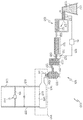
도 1은 유리 리본을 드로우하기 위한 퓨전 다운 드로우 장치를 포함하는 유리 가공 장치의 개략도이다.
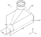
도 2는 본 개시에 따른 예시적인 유리 성형 장치의 사시도이다.
도 3은 도 1의 상기 유리 성형 장치의 분해 사시도이다.
도 4는 본 개시에 따른 압력 탱크의 사시도이다.
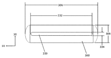
도 5는 도 4의 상기 압력 탱크의 저면도이다.
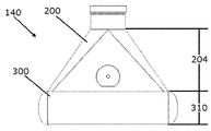
도 6은 도 1의 상기 유리 성형 장치의 측면도이다.
도 7은 본 개시에 따른 또다른 유리 성형 장치의 사시도이다.
도 8은 도 5의 상기 유리 성형 장치의 분해 사시도이다.
도 9는 본 개시에 따른 압력 탱크의 상면도이다.
도 10은 도 8의 상기 압력 탱크의 저면도이다.
도 11은 본 개시에 따른 또다른 유리 성형 장치의 정면도이다.
도 12는 도 11의 상기 유리 성형 장치의 측면도이다.
도 13은 도 11에 도시된 상기 유리 성형 장치의 절단도이다.
도 14는 성형 롤들을 포함하는 도 11의 상기 유리 성형 장치의 측면도이다.
도 15는 상기 유리 성형 장치를 통한 유체 흐름의 예측을 나타내는 도 11의 상기 유리 성형 장치의 사시도이다.
도 16은 도 11의 상기 유리 성형 장치를 통한 용융 유리의 속도 프로파일들을 나타내는 그래프이다.
도 17은 상기 유리 성형 장치의 표면 본 미제스 응력(MPa)의 예측을 나타내는 도 11의 상기 유리 성형 장치의 측면도이다.
도 18은 본 개시에 따른 또다른 유리 성형 장치의 측면도이다.
실시예들의 특징들 및 이점들이 도면들과 함께 아래 제시된 상세한 설명으로부터 보다 명백해질 것이며, 도면들에서 동일한 참조 기호들은 대응하는 구성 요소들을 지칭한다.BRIEF DESCRIPTION OF THE DRAWINGS Figure 1 is a schematic view of a glass processing apparatus including a fusion down draw apparatus for drawing glass ribbon.
2 is a perspective view of an exemplary glass forming apparatus according to the present disclosure;
3 is an exploded perspective view of the glass molding apparatus of FIG.
4 is a perspective view of a pressure tank according to the present disclosure;
Fig. 5 is a bottom view of the pressure tank of Fig. 4;
Figure 6 is a side view of the glass forming apparatus of Figure 1;
7 is a perspective view of another glass forming apparatus according to the present disclosure;
8 is an exploded perspective view of the glass molding apparatus of FIG.
9 is a top view of the pressure tank according to the present disclosure;
Fig. 10 is a bottom view of the pressure tank of Fig. 8; Fig.
11 is a front view of another glass forming apparatus according to the present disclosure;
12 is a side view of the glass forming apparatus of Fig.
13 is a cut-away view of the glass forming apparatus shown in Fig.
Figure 14 is a side view of the glass forming apparatus of Figure 11 comprising forming rolls.
15 is a perspective view of the glass forming apparatus of FIG. 11 showing the prediction of fluid flow through the glass forming apparatus;
16 is a graph showing the velocity profiles of the molten glass through the glass forming apparatus of FIG.
Fig. 17 is a side view of the glass molding apparatus of Fig. 11 showing the prediction of the surface-unmixed stress (MPa) of the glass molding apparatus. Fig.
18 is a side view of another glass forming apparatus according to the present disclosure;
BRIEF DESCRIPTION OF THE DRAWINGS The features and advantages of embodiments will become more apparent from the detailed description set forth below when taken in conjunction with the drawings in which the same reference symbols refer to corresponding elements.
본 개시의 실시예들은 이제 첨부된 도면들을 참조하여 상세히 설명될 것이다. "일 실시예", "실시예", "예시적인 실시예" 등에 대한 참조는 기술된 실시예가 특정한 특징, 구조, 또는 특성을 포함할 수 있다는 것을 나타내나, 모든 실시예가 그 특정한 특징, 구조, 또는 특성을 포함할 필요는 없을 수 있다. 또한, 이러한 문구들은 동일한 실시예를 참조할 필요가 없다. 또한, 특정한 특징, 구조, 또는 특성이 실시예와 관련하여 기술될 때, 명시적으로 기술되었는지 여부에 무관하게 다른 실시예들과 관련하여 이러한 특징, 구조, 또는 특성에 영향을 미치는 것은 당엽계의 통상의 기술자의 지식 내인 것으로 한다. Embodiments of the present disclosure will now be described in detail with reference to the accompanying drawings. Reference to "an embodiment", "an embodiment", "an example embodiment", etc., indicates that the described embodiments may include a particular feature, structure, or characteristic, Or < / RTI > characteristics. Further, these phrases need not refer to the same embodiment. Also, when a particular feature, structure, or characteristic is described in connection with an embodiment, whether affecting such feature, structure, or characteristic in relation to other embodiments, whether explicitly described or not, And it is assumed to be within the knowledge of an ordinary technician.
유리 시트들은 흔히 플로트, 슬롯 드로우, 다운 드로우, 퓨전 다운 드로우, 업드로우, 또는 임의의 다른 성형 공정들을 포함하는 다양한 리본 성형 공정들에 의해 유리 리본이 성형될 수 있는 성형체에 용융 유리를 흐르게함으로써 제조된다. 이들 공정들 중 임의의 것으로부터의 유리 리본은 이후 나뉘어 디스플레이 응용을 포함하나 이에 제한되지 않는 원하는 응용으로의 추가적인 가공에 적합한 하나 이상의 유리 시트들을 제공할 수 있다. 예를 들어, 상기 하나 이상의 유리 시트들은 액정 디스플레이들(LCDs), 전기영동 디스플레이들(EPD), 유기 발광 다이오드 디스플레이들(OLEDs), 플라즈마 디스플레이 패널들(PDPs) 등을 포함하는 다양한 디스플레이 응용들에 사용될 수 있다. 유리 시트들은 한 위치로부터 다른 곳으로 수송될 수 있다. 상기 유리 시트들은 유리 시트들의 스텍을 제자리에 고정하도록 설계된 통상적인 서포트 프레임으로 수송될 수 있다. 또한, 인터리프 물질은 각각의 인접한 유리 시트 사이에 위치될 수 있어 사이의 접촉을 방지하는데 도움이되며, 따라서 유리 시트들의 깨끗한 표면들을 보존한다.Glass sheets can be produced by flowing molten glass into a shaped body where the glass ribbon can be formed by various ribbon forming processes, often including float, slot draw, down draw, fusion down draw, up draw, do. The glass ribbon from any of these processes may then be divided to provide one or more glass sheets suitable for further processing into the desired application, including but not limited to display applications. For example, the one or more glass sheets can be used in a variety of display applications including liquid crystal displays (LCDs), electrophoretic displays (EPD), organic light emitting diode displays (OLEDs), plasma display panels Can be used. Glass sheets can be transported from one location to another. The glass sheets can be transported into a conventional support frame designed to hold the stack of glass sheets in place. In addition, the interleaved material may be positioned between each adjacent glass sheet to help prevent contact therebetween, thus preserving the clean surfaces of the glass sheets.
본 명세서에 개시된 특정한 실시예들은 예시적이며 따라서 비제한적으로 의도된다는 것이 이해될 것이다. 이와 같이, 본 개시는 유리 리본 및 유리 시트 중 적어도 하나를 가공하는 방법들 및 장치에 관한 것이다. 일부 실시예들에서, 가공되는 유리 리본은 유리 제조 장치로부터 성형될 수 있거나, 유리 제조 장치로부터 성형되자 마자 제공될 수 있거나, 스폴로부터 풀릴 수 있는 미리 성형된 유리 리본의 스풀로부터 제공될 수 있거나, 또는 프리스탠딩 유리리본으로 제공될 수 있다. 일부 실시예들에서, 가공되는 유리 시트는 유리 제조 장치로부터 성형될 수 있거나, 유리 리본으로부터 분리된 유리 시트로 제공될 수 있거나, 또다른 유리 시트로부터 분리된 유리 시트로 제공될 수 있거나, 유리 시트들의 스풀로부터 풀린 유리 시트로서 제공될 수 있거나, 유리 시트들의 스택으로부터 얻은 유리 시트로서 제공될 수 있거나, 프리스탠딩 유리 시트로서 제공될 수 있다.It will be appreciated that the specific embodiments disclosed herein are illustrative and thus are not intended to be limiting. As such, the present disclosure is directed to methods and apparatus for processing at least one of a glass ribbon and a glass sheet. In some embodiments, the processed glass ribbon may be molded from a glass manufacturing apparatus, provided as soon as it is molded from the glass manufacturing apparatus, or may be provided from a spool of preformed glass ribbon that can be unwound from the spool, Or as a free-standing glass ribbon. In some embodiments, the processed glass sheet may be molded from a glass manufacturing apparatus, provided with a glass sheet separated from the glass ribbon, or provided with a glass sheet separated from another glass sheet, Or may be provided as a glass sheet obtained from a stack of glass sheets, or may be provided as a free-standing glass sheet.
일 실시예에서, (아래 보다 상세히 기술된 바와 같이) 상기 유리 가공 장치(100)는 상기 유리 리본(103)에 유리 제조 장치(101), 예컨대 슬롯 드로우 장치, 플로트 배쓰 장치, 다운 드로우 장치, 업 드로우 장치, 프레스롤링 장치, 또는 다른 유리 리본 제조 장치를 제공한다. 도 1은 유리 성형기(140)의 사용을 통해 유리 시트들(104)로의 후속적인 가공을 위해 유리 리본(103)을 퓨전 드로잉 하기 위한 퓨전 다운 드로우 장치(101)인 유리 제조 장치(101)를 개략적으로 도시한다. 물론 및 아래 설명된 바와 같이, 상기 유리 제조 장치(101)는 슬롯 드로우 장치 또는 다른 유리 리본 제조 장치일 수 있으며 제조 방법에 따라 상이한 유리 성형기들을 포함할 수 있다 (예를 들어, 도 2 내지 도 5 참조). In one embodiment, the glass-working
상기 퓨전 다운 드로우 장치(101)는 저장 통(109)으로부터 배치 물질(107)을 수용하도록 배향된 용융 용기(105)를 포함할 수 있다. 상기 배치 물질(107)은 모터(113)에 의해 구동되는 배치 운반 장치(111)에 의해 도입될 수 있다. 선택적인 제어기(115)는 화살표(117)에 의해 표시된 바와 같이, 상기 용융 용기(105) 내로 원하는 양의 배치 물질(107)을 도입하도록 상기 모터(113)를 활성하시키도록 구성될 수 있다. 유리 용융 프로브(119)는 스탠드파이프(123) 내의 용융 물질(121)의 수준을 측정하고 통신 라인(125)을 통해 상기 제어기(115)에 측정된 정보를 통신하기 위해 사용될 수 있다.The fusion down-
상기 퓨전 다운 드로우 장치(101)는 또한 상기 용융 용기(105)로부터 하류에 위치되고 제1 연결 도관(129)을 통해 상기 용융 용기(105)에 결합된 청징 용기(fining vessel)(127)를 포함할 수 있다. 일부 실시예들에서, 용융 물질(121)은 상기 용융 용기(105)로부터 상기 청징 용기(127)로 상기 제1 연결 도관(129)을 통해 중력에 의해 공급될 수 있다. 예를 들어, 중력은 상기 용융 물질(121)이 상기 제1 연결 도관(129)의 내부 경로를 통해 상기 용융 용기(105)로부터 상기 청징 용기(127)로 통과하도록 몰아가는 역할을 할 수 있다. 청징 용기(127) 내에서, 다양한 기술들에 의해 상기 용융 물질(121)로부터 버블들이 제거될 수 있다.The Fusion down-
상기 퓨전 다운 드로우 장치(101)는 상기 청징 용기(127)로부터 하류에 위치될 수 있는 혼합 챔버(131)를 더 포함할 수 있다. 상기 혼합 챔버(131)는 용융 물질(121)의 균일한 조성을 제공하고, 이로써 상기 청징 용기(127)를 빠져나가는 상기 용융 물질(121) 내에 존재할 수 있는 불균일성을 감소시키거나 제거하기 위해 사용될 수 있다. 도시된 바와 같이, 상기 청징 용기(127)는 제2 연결 도관(135)을 통해 상기 혼합 챔버(131)에 결합될 수 있다. 일부 실시예들에서, 용융 물질(121)은 상기 청징 용기(127)로부터 상기 혼합 챔버(131)로 상기 제2 연결 도관(135)을 통해 중력에 의해 공급될 수 있다. 예를 들어, 중력은 상기 용융 물질(121)이 상기 청징 용기(127)로부터 상기 혼합 챔버(131)로 상기 제2 연결 도관(135)의 내부 경로를 통해 통과하도록 몰아가는 역할을 할 수 있다.The fusion down-
상기 퓨전 다운 드로우 장치(101)는 상기 혼합 챔버(131)로부터 하류에 위치될 수 있는 운반 용기(133)를 더 포함할 수 있다. 상기 운반 용기(133)는 유리 성형기(140) 내로 공급될 상기 용융 물질(121)을 컨디셔닝할 수 있다. 예를 들어, 상기 운반 용기(133)는 조절하고 상기 유리 성형기(140)로 일정한 흐름의 용융 물질(121)을 제공하기 위한 축적기 및/또는 흐름 제어기로 역할할 수 있다. 도시된 바와 같이, 상기 혼합 챔버(131)는 제3 연결 도관(137)을 통해 상기 운반 용기(133)에 연결될 수 있다. 일부 실시예들에서, 용융 물질(121)은 상기 혼합 챔버(131)로부터 상기 운반 용기(133)로 상기 제3 연결 도관(137)을 통해 중력에 의해 공급될 수 있다. 예를 들어, 중력은 상기 용융 물질(121)이 상기 제3 연결 도관(137)의 내부 경로를 통해 상기 혼합 챔버(131)로부터 상기 운반 용기(133)로 통과하도록 몰아가도록 역할할 수 있다.The fusion down-
더 도시되는 바와 같이, 운반 파이프(139)는 용융 물질(121)을 상기 퓨전 다운 드로우 장치(101)의 상기 유리 성형기(140)로 운반하도록 위치될 수 있다. 아래 보다 상세히 논의된 바와 같이, 상기 유리 성형기(140)는 성형 용기(143)의 루트(145)로부터 상기 용융 물질(121)을 유리 리본(103)으로 드로우할 수 있다. 도시된 실시예에서, 상기 성형 용기(143)는 상기 운반 용기(133)의 상기 운반 파이프(139)로부터 용융 물질(121)을 수용하도록 배향된 입구(141)를 구비할 수 있다.As further shown, the transport pipe 139 can be positioned to transport the
도 1은 예시적인 유리 분리기(149)의 개략도를 도시한다. 도시된 바와 같이, 예시적인 유리 분리기(149)는 유리 리본(103)의 제1 수직 엣지(153)와 유리 리본(103)의 제2 수직 엣지(155) 사이의, 상기 유리 성형기(140)의 드로우 방향(177)을 가로지르는, 유리 리본(103)의 폭(W)을 따라 연장되는, 횡방향 분리 경로(151)를 따라 유리 리본(103)으로부터 유리 시트(104)를 분리할 수 있다.FIG. 1 shows a schematic view of an
유리 성형기(140)는 원하는 크기의 유리 리본(103)을 운반하기 위해 스케일링가능할 수 있다. 일부 실시예들에서, 유리 리본(103)은 약 50mm 내지 약 1.5m의 폭(W)을 가질 수 있다. 추가적인 실시예들에서, 유리 리본(103)은 약 50mm 내지 약 500mm의 폭(W)을 가질 수 있다. 유리 리본(103)은 약 150mm 내지 약 300mm의 폭을 가질 수 있다. 일부 실시예들에서, 상기 유리 리본(103)의 폭(W)은 약 20mm 내지 약 4000mm, 예컨대 약 50mm 내지 약 4000mm, 예컨대 약 100mm 내지 약 4000mm, 예컨대 약 500mm 내지 약 4000mm, 예컨대 약 1000mm 내지 약 4000mm, 예컨대 약 2000mm 내지 약 4000mm, 예컨대 약 3000mm 내지 약 4000mm, 예컨대 약 20mm 내지 약 3000mm, 예컨대 약 50mm 내지 약 3000mm, 예컨대 약 100mm 내지 약 3000mm, 예컨대 약 500mm 내지 약 3000mm, 예컨대 약 1000mm 내지 약 3000mm, 예컨대 약 2000mm 내지 약 3000mm, 예컨대 약 2000mm 내지 약 2500mm, 및 그 사이의 모든 범위들 및 하위 범위들일 수 있다.The
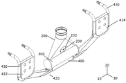
유리 성형기(140)의 또다른 실시예가 도 2 내지 도 5에 도시된다. 이 유리 성형기(140)는 상기 운반 파이프(139)와 접속할 수 있으며, 유리 리본을 하나 이상의 하류 성형 롤들(60)(도 14 참조)로 운반할 수 있다. 도 2에 도시된 바와 ?이, 유리 성형기(140)는 축(10)을 따라 연장되는 폭(142), 축(20)을 따라 연장되는 높이(144), 및 축(30)을 따라 개구 방향으로 연장되는 치수(148)을 가질 수 있다 (도 2). "폭" 및 "두께"는 또한, 주로 유리 리본(103)의 치수들과 관련하여, 각각 축들(10 및 30)의 방향으로의 거리를 기술하기 위해 본 명세서에 사용된다. 유리 성형기(140)는 유리 리본(103)을 드로우하기 위한 상부 트랜지션 부재(200) 및 압력 탱크(300)를 포함할 수 있다. 압력 탱크(300)가 상기 용융 유리가 압력 탱크 챔버(301) 내에 수집되고 하부 오리피스(330)에 걸쳐 상기 용융 유리를 향하게할 수 있으므로, 유리 성형기(140)는 용융 유리 서플라이로부터 유리 흐름 리본(103)을 비교적 짧은 트랜지션 높이(144)로 드로우할 수 있다 (도 3).Another embodiment of the
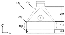
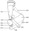
도 2 및 도 3에 도시된 바와 같이, 상부 트랜지션 부재(200)는 상부 트랜지션 부재(200)의 상단(210)에서 용융 유리 서플라이에 고정될 수 있다. 예를 들어, 상단(210)은 용접 또는 브레이징(brazing)에 의해 용융 유리 서플라이에 금속 가공적으로 결합될 수 있다. 용융 유리는 상부 트랜지션 부재(200)의 트랜지션 챔버(201)를 통해 흐를 수 있다. 상부 트랜지션 부재(200)는 용융 유리를 상단(210)의 중심으로부터 하단(220)의 하단 폭(222)에 걸쳐 분배할 수 있다. 상부 트랜지션 부재는 도 6에 도시된 바와 같이 높이(204)를 가질 수 있다. 상부 트랜지션 부재(200)는 높이(204)를 따라 테이퍼링되어 하단 폭(222)은 상단 폭(212)보다 클 수 있다. 도 3에 도시된 바와 같이, 상단 개구 거리(214)는 하단 개구 거리(224)보다 클 수 있다. 일부 실시예들에서, 상부 트랜지션 부재(200)는 정면, 배면, 또는 측면에서 보았을 때 사다리꼴 형상을 가질 수 있다.As shown in FIGS. 2 and 3, the
본 명세서에 사용된 바와 같이, 용어 "오리피스(orifice)"는 유체 흐름을 전달하도록 구성된 유리 성형기(140)의 일부 내의 개구를 지칭한다. 오리피스는 하나의 개구(예를 들어 도 3) 또는 서포트들에 의해 분리된 복수의 개구들(예를 들어, 도 8)을 포함할 수 있다.As used herein, the term "orifice" refers to an opening in a portion of a
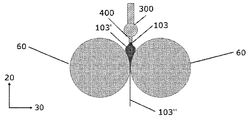
압력 탱크(300)는 상부 트랜지션 부재(200)의 하단(220)에 부착될 수 있다. 예를 들어, 압력 탱크(300)는 용접 또는 브레이징에 의한 금속 가공적 결합에 의해 상부 트랜지션 부재(200)에 고정될 수 있다. 압력 탱크(300)는 그 내에 형성된 상부 오리피스(320) 및 하부 오리피스(330)를 포함할 수 있어 압력 탱크 폭(306)(도 3 참조)은 상부 오리피스 폭(322) 및 하부 오리피스 폭(332)(도 4 참조)보다 클 수 있다. 용융 유리는 상부 트랜지션 부재(200)로부터 상부 오리피스(320)를 통해 압력 탱크(300)에 들어갈 수 있다. 용융 유리는 압력 탱크 챔버(301)를 통해 흐를 수 있다. 상부 오리피스(320)에서 압력 탱크(300)에 들어가는 용융 유리는 상기 흐름의 줌심에서 흐름의 속도가 가장 큰 흐름을 가질 수 있다. 압력 탱크(300)는 적어도 부분적으로 하부 오리피스(330)에서의 흐름 제약으로 인하여 압력 탱크 챔버(301) 내의 용융 유리를 수집하고 상기 용융 유리가 압력 탱크 폭(306)(도 5 참조)에 걸쳐 퍼지도록 허용하므로, 압력 탱크(300)는 상기 용융 유리 흐름을 압력 탱크(300)의 중심으로부터 하부 오리피스(330)에서의 압력 탱크(300)의 단부들(304)로 재분배할 수 있다. 압력 탱크 단부들(304)은 압력 탱크(300)를 밀봉한다. 압력 탱크 단부들(304)은 물질 응력 및 피로를 감소시키기 위해 바깥쪽으로 휠 수 있다.The
일부 실시예들에서, 상부 트랜지션 부재(200)는 유리 시트 성형기(140)로부터 생략될 수 있으며, 압력 탱크(300)는 도 18에 도시된 바와 같이 용융 유리 서플라이에 바로 부착될 수 있다.In some embodiments, the
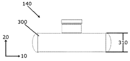
도 3 및 도 4에 도시된 바와 같이, 압력 탱크(300)는 폭(306), 개구 치수(308), 및 높이(310)를 가질 수 있다. 이들 치수들은 압력 탱크(300)의 내부의 크기를 지칭하며, 압력 탱크(300)의 벽들에 의해 차지되는 거리를 포함하지 않는다. 개구 치수(308)는 축(30)을 따른 상기 개구 방향으로의 압력 탱크(300)의 가장 큰 치수일 수 있다. 압력 탱크는 용융 유리 흐름을 그 내부 영역에 수집하여 하부 오리피스(330)의 하부 오리피스 폭(332)에 걸쳐 상기 흐름을 재분배하는 임의의 형상일 수 있다. 예를 들어, 압력 탱크(300)의 형상은 직사각 프리즘, 정육면체, 삼각 프리즘, 원뿔, 구, 피라미드, 또는 다른 형상들일 수 있다. 일부 실시예들에서, 압력 탱크(300)는 상기 개구 치수(308) 및 높이(310)가 동일한 실린더일 수 있다. 압력 탱크(300)의 폭은 유리 리본(103)의 면 내에 놓이는 축(10)을 따라 연장될 수 있어 압력 탱크(300)는 유리 흐름의 방향에 수직하게 위치된다. 다른 실시예에서, 압력 탱크(300)는 테이퍼링되는 형상을 가질 수 있어 상기 탱크(300)의 하단의 표면적이 상기 탱크(300)의 상부 단부의 표면적보다 크다. 원통형 형상들은 내부 압력으로 인한 변형에 더 잘 견딜 수 있으므로 선호된다.3 and 4, the
도 4에 도시된 바와 같이, 상부 오리피스(320)는 상부 오리피스 폭(322) 및 상부 오리피스 개구 거리(324)를 가질 수 있다. 하부 오리피스(330)는 하부 오리피스 폭(332) 및 하부 오리피스 개구 거리(334)를 가질 수 있다. 일부 실시예들에서, 상부 오리피스(320) 및 하부 오리피스(330)는 대략 동일한 크기일 수 있다. 일부 실시예들에서, 하부 오리피스 폭(332)은 상부 오리피스 폭(322)보다 클 수 있다. 일부 실시예에서, 하부 오리피스 폭(332)은 대략 50mm 내지 대략 1.5m일 수 있다. 추가적인 실시예에서, 하부 오리피스 폭(332)은 대략 50mm 내지 대략 500mm일 수 있다. 또다른 실시예에서, 하부 오리피스 폭(332)은 대략 150mm 내지 대략 300mm일 수 있다. 일부 실시예들에서, 하부 오리피스(330)를 통한 용융 유리의 유동 밀도는 시간 당 센티미터 당 1 킬로그램 내지 대략 시간 당 셍티미터 당 36 킬로그램일수 있다.4, the
상기 개구 치수(308)가 상기 하부 오리피스(330)의 상기 개구 거리(334)보다 크므로(도 5 참조), 용융 유리는 압력 탱크(300)의 폭(306)을 따라 상기 용융 유리를 분배하는 압력 탱크(300) 내에서 압력을 받는다.Since the
일부 실시예들에서, 압력 탱크 개구 치수(308)는 상부 오리피스 개구 거리(324)보다 클 수 있다. 또다른 실시예에서, 압력 탱크 개구 치수(308)는 하부 오리피스 개구 거리(334)보다 클 수 있다. 추가적인 실시예에서, 압력 탱크 개구 치수(308)는 상부 오리피스 개구 거리(324) 및 하부 오리피스 개구 거리(334)보다 클 수 있다.In some embodiments, the pressure
일부 실시예들에서, 압력 탱크 개구 치수(308)는 상부 오리피스 개구 거리(324)보다 대략 2 내지 대략 10배 더 클 수 있다. 압력 탱크 개구 치수(308)는 상부 오리피스 개구 거리(324)보다 대략 4 내지 대략 6배 더 클 수 있다. 일부 실시예들에서, 압력 탱크 개구 치수(308)는 하부 오리피스 개구 거리(334)보다 대략 2 내지 대략 10배 더 클 수 있다. 압력 탱크 개구 치수(308)는 하부 오리피스 개구 거리(334)보다 대략 4 내지 대략 6배 더 클 수 있다.In some embodiments, the pressure
일부 실시예들에서, 압력 탱크 개구 치수(308)는 상부 트랜지션 부재(200)의 하단 개구 거리(224)보다 클 수 있다. 또다른 실시예에서, 압력 탱크 개구 치수(308)는 상부 트랜지션 부재(200)의 하단 개구 거리(224)보다 대략 2 내지 대략 10배 더 클 수 있다. 추가적인 실시예에서, 압력 탱크 개구 치수(308)는 상부 트랜지션 부재(200)의 하단 개구 거리(224)보다 대략 4 내지 대략 6배 더 클 수 있다.In some embodiments, the pressure
유리 성형기(140)는 높은 온도들 및 압력들에서 물질 변형, 즉 크리프(creep)에 견딜 수 있는 물질일 수 있다. 유리 성형기(140)는 대략 1400도씨 내지 대략 1700도씨의 온도에서 용융 유리를 운반하는 물질일 수 있다. 일부 실시예들에서, 유리 성형기(140)는 유리 성형기(140)가 높은 온도의 용융 유리를 운반하기 위해 높은 온도 및 압력에 양립가능하게하는 백금 및 로듐 합금일 수 있다. 일부 실시예들에서, 유리 성형기(140)는 도핑된 PtRh 합금일 수 있다. 일부 실시예들에서, 유리 성형기(140)는 80/20 PtRh 합금일 수 있다. 또다른 실시예에서, 유리 성형기(140)는 90/10 PtRh 합금일 수 있다. 추가적인 실시예들에서, 유리 성형기(140)는 분산 경화 백금(dispersion hardened platinum, DHP)일 수 있다. 추가적인 실시예에서, 유리 성형기(140)는 지르콘 도핑된 물질일 수 있다.The
일부 실시예들에서, 유리 성형기(140)를 통해 흐르는 용융 유리의 점도는 다음 중 하나 이상을 조절함으로써 제어될 수 있다: 용융 유리 서플라이의 흐름 거리 및 압력; 용융 유리 서플라이의 온도; 하부 오리피스(330)의 폭; 및 하부 오리피스(330)의 개구 거리(334). 유리 성형기(140)를 통해 흐르는 용융 유리의 점도는 대략 50 프와즈(poises) 내지 대략 20,000 프와즈일 수 있다. 추가적인 실시예들에서, 유리 성형기(140)를 통해 흐르는 용융 유리의 점도는 대략 1,000 프와즈 내지 대략 5,000 프와즈일 수 있다. 유리 성형기(140) 내의 위치에서 상기 용융 유리의 점도는 그 위치에서의 유리 성형기(140)의 온도에 기초하여 결정될 수 있다. 일부 실시예들에서, 유리 성형기(140)는 이들 위치들에서 용융 유리의 점도를 결정하기 위해 유리 성형기(140) 내의 하나 이상의 위치들에서의 온도를 결정하기 위한 온도 센서들(미도시)을 포함할 수 있다.In some embodiments, the viscosity of the molten glass flowing through the
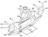
이제 도 7 내지 도 10을 참조하면, 유리 성형기(140)는 시간에 걸쳐 그 형상을 유지하고 외부 보강재들 없이 높은 온도 및 유리 압력에서 물질 크리프를 회피하기 위해 내부 구조 보강재들을 포함할 수 있다. 상기 내부 구조 보강재들로 인하여, 유리 성형기(140)는 시간에 걸쳐 그 형상을 유지히고 높은 온도 및 유리 압력에서 물질 크리프를 회피하기 위해 외부 기계 보강제를 필요로하지 않는다. 예를 들어, 상부 트랜지션 부재(200)는 상부 트랜지션 부재 서포트(230)를 포함할 수 있다. 상부 트랜지션 부재 서포트(230)는 축(30)을 따라 연장될 수 있으며, 트랜지션 챔버(201)에 걸쳐 연장될 수 있다. 일부 실시예들에서, 상부 트랜지션 부재 서포트(230)는 상부 트랜지션 부재 서포트(230)의 단부들에 위치되는 서포트 플레이트들(232)을 사용하여 상부 트랜지션 부재(200)에 부착될 수 있다. 서포트 플레이트들(232)은 상부 트랜지션 부재 서포트(230)에 인접한 상부 트랜지션 부재(200)의 벽의 부분들 내의 응력 집중을 감소시킬 수 있다. 일부 실시예들에서, 상부 트랜지션 부재 서포트(230) 및 서포트 플레이트들(232)은 예를 들어 브레이징 또는 용접에 의해 상부 트랜지션 부재(200)에 금속 가공적으로 결합될 수 있다.Referring now to Figures 7 to 10, the
도 8 및 도 9에 도시된 바와 같이, 압력 탱크(300)는 하나 이상의 상부 압력 탱크 서포트들(326)을 포함할 수 있다. 상부 압력 탱크 서포트들(326)은 축(30)을 따라 연장될 수 있으며, 상부 오리피스(320)의 벌어짐을 막기 위해 상부 오리피스(320)에 걸쳐 연장될 수 있다. 일부 실시예들에서, 압력 탱크(300)는 오리피스(320)에 걸쳐 연장되는 두 상부 압력 탱크 서포트들(326)을 포함할 수 있다. 일부 실시예들에서, 압력 탱크(300)는 상부 오리피스(320)에 걸쳐 연장되는 세개의 상부 압력 탱크 서포트들(326)을 포함할 수 있다.8 and 9, the
상부 압력 탱크 서포트들(326)은 예를 들어 용접 또는 브레이징에 의한 금속 가공적 결합에 의해 상부 오리피스(320)에 걸쳐 영구적으로 고정될 수 있다. 일부 실시예들에서, 상부 오리피스(320)는 압력 탱크 벽(302) 내에 형성된 복수의 개구들을 포함할 수 있다. 이 실시예에서, 상부 오리피스(320)를 위한 상기 복수의 개구들을 형성하도록 압력 탱크 벽(302)의 부분들이 제거될 수 있다. 상부 압력 탱크 서포트들(326)은 압력 탱크 벽(302) 내에 일체로 형성될 수 있다. 예를 들어, 압력 탱크(300) 제조 시, 압력 탱크 벽(302)은 일체의 물질 조각으로 시작할 수 있으며 압력 탱크 벽(302)의 부분들은 제거되어 상부 오리피스(320)를 위한 상기 복수의 개구들을 형성한다. 상부 오리피스(320)를 위한 각각의 개구들 사이에 남아있는 하나 이상의 부분들의 압력 탱크 벽(302)은 하나 이상의 일체형의 상부 압력 탱크 서포트들(326)을 형성한다.The upper pressure tank supports 326 may be permanently secured over the
도 10에 도시된 바와 같이, 압력 탱크(300)는 하나 이상의 하부 압력 탱크 서포트들(336)을 포함할 수 있다. 하부 압력 탱크 서포트들(336)은 축(30)을 따라 연장될 수 있으며 하부 오리피스(330)의 벌어짐을 막기 위해 하부 오리피스(330)에 걸쳐 연장될 수 있다. 일부 실시예들에서, 압력 탱크(300)는 오리피스(330)에 걸쳐 연장되는 2개의 하부 압력 탱크 서포트들(336)을 포함할 수 있다. 또다른 실시예에서, 압력 탱크(300)는 하부 오리피스(330)에 걸쳐 연장되는 세개의 하부 압력 탱크 서포트들(336)을 포함할 수 있다.As shown in FIG. 10, the
예를 들어 용접 또는 브레이징에 의한 금속 가공적 결합에 의해 하부 압력 탱크 서포트들(336)은 하부 오리피스(330)에 걸쳐 영구적으로 고정될 수 있다. 일부 실시예들에서, 하부 오리피스(330)는 압력 탱크 벽(302) 내에 형성된 복수의 개구들을 포함할 수 있다. 이 실시예에서, 압력 탱크 벽(302)의 부분들은 하부 오리피스(330)를 위한 상기 복수의 개구들을 형성하도록 제거될 수 있다. 하부 압력 탱크 서포트들(336)은 압력 탱크 벽(302) 내에 일체로 형성될 수 있다. 예를 들어, 압력 탱크(300) 제조 시, 압력 탱크 벽(302)은 일체의 물질 조각으로 시작할 수 있으며, 하부 오리피스(330)를 위한 상기 복수의 개구들을 형성하도록 제거될 수 있다. 하부 오리피스(330)를 위한 각각의 개구들 사이에 남아있는 하나 이상의 부분들의 압력 탱크 벽(302)은 하나 이상의 일체형의 하부 압력 탱크 서포트들(336)을 형성한다.The lower pressure tank supports 336 may be permanently fixed over the
일부 실시예들에서, 압력 탱크(300)는 압력 탱크(300)의 높이를 따라 위치된 하나 이상의 탱크 서포트들을 포함할 수 있다. 이 실시예에서, 상기 하나 이상의 탱크 서포트들은 압력 탱크 챔버(301)에 걸쳐 연장될 수 있다.In some embodiments, the
유리 성형기(140) 내의 상기 내부 보강재들은 물질 변형 및 크리프를 방지한다. 예를 들어, 하부 압력 탱크 서포트들(336)은 하부 오리피스(330)에서의 물질 변형 및 크리프를 방지하므로, 하부 오리피스(330)의 상기 개구 거리(334)는 하부 오리피스 폭(332)을 따라 일정할 수 있다.The internal stiffeners in the
상부 압력 탱크 서포트들(326) 및 하부 압력 탱크 서포트들(336)은 압력 탱크(300) 및 하부 오리피스(330)를 통해 흐르는 용융 유리의 분리된 흐름들을 생성할 수 있다. 예를 들어, 상부 압력 탱크 서포트들(326) 및 하부 압력 탱크 서포트들(336)은 압력 탱크(300) 및 하부 오리피스(330)를 통해 흐르는 상기 용융 유리를 용융 유리의 둘 이상의 흐름들로 분리할 수 있다.The upper pressure tank supports 326 and the lower pressure tank supports 336 may produce separate flows of molten glass flowing through the
일부 실시예들에서, 도 7 및 도 8에 도시된 바와 같이, 유리 성형기(140)는 압력 탱크(300)에 부착된 슬롯 익스텐션(400)을 포함할 수 있다. 슬롯 익스텐션(400)의 내부 영역(401)은 압력 탱크 챔버(301)와 유체 상통할 수 있다. 상부 압력 탱크 서포트들(326) 및 하부 압력 탱크 서포트들(336)로 인한 용융 유리의 분리된 흐름들은 슬롯 익스텐션(400)내에 수렴하여 유리 리본(103)으로 융합될 수 있다.In some embodiments, as shown in FIGS. 7 and 8, the
도 11 및 도 12에 도시된 바와 같이, 슬롯 익스텐션(400)은 슬롯 익스텐션 높이(404), 슬롯 익스텐션 폭(406), 및 슬롯 익스텐션 개구 거리(408)를 포함할 수 있다. 일부 실시예들에서, 슬롯 익스텐션 폭(406)은 하부 오리피스 폭(332)보다 다소 커서 슬롯 익스텐션(400)이 완전히 하부 오리피스(330)를 둘러싼다. 일부 실시예들에서, 슬롯 익스텐션 폭(406)은 대략 50mm 내지 대략 1.5m 일 수 있다. 추가적인 실시예에서, 슬롯 익스텐션 폭(406)은 대략 50mm 내지 대략 500mm일 수 있다. 또다른 실시예에서, 슬롯 익스텐션 폭(406)은 대략 150mm 내지 대략 300mm일 수 있다.As shown in FIGS. 11 and 12, the
일부 실시예들에서, 슬롯 익스텐션 높이(404)는 대략 10mm 내지 대략 30mm일 수 있다. 또다른 실시예에서, 슬롯 익스텐션 높이(404)는 대략 15mm 내지 대략 25mm일 수 있다. 추가적인 실시예에서, 슬롯 익스텐션 높이(404)는 대략 18mm 내지 대략 22mm일 수 있다. 또다른 실시예에서, 슬롯 익스텐션 높이(404)는 대략 20mm일 수 있다.In some embodiments, the
슬롯 익스텐션 개구 거리(408)는 하부 오리피스 개구 거리(334)보다 다소 클 수 있어 슬롯 익스텐션(400)은 하부 오리피스(330)를 완전히 둘러싼다. 일부 실시예들에서, 압력 탱크 개구 치수(308)는 슬롯 익스텐션 개구 거리(408)보다 대략 2 내지 대략 10배 더 클 수 있다. 압력 탱크 개구 치수(308)는 슬롯 익스텐션 개구 거리(408)보다 대략 4 내지 대략 6배 더 클 수 있다.The slot
도 7 및 도 8에 도시된 바와 같이, 유리 성형기(140)는 또한 냉각으로부터 상기 용융 유리 흐름을 보호하기 위한 열원(420)을 포함할 수 있다. 일부 실시예들에서, 열원(420)은 슬롯 익스텐션(400)일 수 있다. 직접 가열을 통해 열을 발생시키기 위해 열원(420) 및 슬롯 익스텐션(400)을 통해 전류를 공급하기 위해, 열원(420)의 제1 단부(422)는 제1 전기 커넥션에 부착되도록 구성될 수 있고, 열원(420)의 제2 단부(424)는 제2 전기 커넥션에 부착되도록 구성될 수 있다. 직접 가열을 위하여, 제1 단부(422)에의 제1 전기 커넥션 및 제2 단부(424)에의 제2 전기 커넥션은 슬롯 익스텐션(400) 내로 직접적인 전기 입력을 제공할 수 있으며, 물질은 원하는 점도에 따라 실질적으로 일정한 온도에서 유지된다. 또다른 실시예에서, 열원(420)은 인덕션 가열(미도시)을 통해 열을 제공할 수 있다. 또다른 실시예에서, 열원(420)은 슬롯 익스텐션(400)의 외부 표면에 부착된 와인딩 또는 세라믹 가열 구성 요소(미도시)를 포함할 수 있다. 유리 성형기(140)는 또한 열원(420)에 인접하게 위치된 냉각 튜브들(430)을 포함할 수 있다. 냉각 유체는 유리 성형기(140)를 원하는 온도로 유지하기 위해 냉각 튜브들(430)을 통해 통과될 수 있다. 일부 실시예들에서, 유리 성형기(140)는 유리 성형기(140) 내의 하나 이상의 위치들에서 온도를 결정하기 위한 온도 센서들(미도시)을 포함할 수 있다. 상기 온도 센서들은 그 내에 흐르는 용융 유리의 원하는 점도를 달성하기 위해 열원(420)에 대한 적절한 열 셋팅 및 냉각 튜브들(430)에 대한 적절한 냉각 셋팅을 결정하는데 사용될 수 있다.7 and 8, the
일부 실시예들에서, 유리 성형기(140)는 추가적인 가공을 위하여 유리 리본(103)을 운반할 수 있다. 다른 실시예들에서, 도 14에 되시된 바와 같이, 유리 성형기(140)는 수직 롤링 공정과 함께 사용될 수 있으며 유리 리본(103)의 추가적인 가공을 위한 한 쌍의 성형 롤들(60)에 유리 리본(103)을 공급할 수 있다. 상기 쌍의 성형 롤들(60)은 성형되는 유리의 조성 및 점도에 따라 약 500도씨 내지 약 600도씨, 또는 더 높은 범위의 표면 온도에서 온도 제어되는 통상적인 열간 성형 롤들일 수 있다. 성형 롤들의 온도 제어를 위한 공정 및 장치들은 당업계에서 잘 이해되며 따라서 본 명세서에서는 상세히 기술되지 않는다.In some embodiments, the
슬롯 익스텐션(400)은 또한 유리 리본(103)의 흐름의 불안정성을 방지하기 위해 상기 쌍의 성형 롤들(60) 사이에 가능한한 낮게 유리 리본(103)을 운반할 수 있다. 예를 들어, 롤들(60)이 슬롯 익스텐션(400)의 바닥에 의해 형성된 평면을 넘어 연장되게 롤들(60)의 직경은 충분히 클 수 있어 유리 리본(103)의 안정적인 흐름이 롤들(60)에 제공될 수 있다. 도 14에 도시된 바와 같이, 유리 리본(103)은 슬롯 익스텐션(400)을 빠져나갈 수 있으며, 롤들(60)의 상부 상에 축적되어 유리 리본 퍼들(103')을 형성한다. 상기 쌍의 성형 롤들(60)은 상기 유리 리본 퍼들(103')을 프레싱된 유리 리본(103'')으로 평탄화 하고, 얇아지게 하고, 평활화할 수 있다. 유리 리본(103)의 두께는 프레싱된 유리 리본(103'')의 두께보다 클 수 있다. 유리 리본 퍼들(103')의 두께는 유리 리본(103)의 두께보다 클 수 있다.The
유리 성형기가 작동하는 고온 조건들로 인하여, 상기 유리 성형기의 물질은 크리프를 겪을 수 있으며, 이는 상기 유리 성형기를 변형시킨다. 크리프는 상기 유리 성형기가 또한 응력 하에 있는 곳에서 두드러질 수 있다. 크리프는 상기 유리 성형의 변형을 야기할 수 있으며, 이는 저하된 성능을 야기할 수 있다. 예를 들어, 유리가 흐르는 오리피스의 형상의 변화는 상기 유리 성형기의 폭에 걸친 상이한 위치들에서의 유리 흐름의 속도를 변경시킬 수 있다. 크리프를 감소시키는 하나의 방법은 상기 유리 성형기를 내화 물질로 둘러싸는 것이다. 그러나, 상기 내화 물질은 상기 유리 성형기에 벌크를 추가할 수 있다. 이 추가적인 벌크는 성형 롤들에 근접하게 유리 리본을 운반하는 능력을 방해할 수 있다. 본 명세서에 기술된 유리 성형기들의 실시예들은 내화 물질 없이 크리프를 견딜 수 있다. 예를 들어, 80/20 PtRh 합금, 90/10 PtRh 합금, 및 유사한 물질들의 사용, 상부 트랜지션 부재 서포트(230), 상부 압력 탱크 서포트(326), 하부 압력 탱크 서포트(336)의 존재, 및 압력 탱크(300)의 원통형 형상 각각은 크리프 저항성에 기여한다. 단독 또는 조합으로 이들 특징들은 내화 재료의 사용 없이도 크리프에 저항성이 있는 디자인에 기여한다. 모든 이들 특징들의 조합은 크리프 저항성을 위하여 특히 선호된다.Due to the high temperature conditions at which the glass forming machine operates, the material of the glass forming machine may undergo creep, which deforms the glass forming machine. The creep can be noted where the glass molding machine is also under stress. Creep may cause deformation of the glass molding, which may result in degraded performance. For example, a change in the shape of the orifice through which the glass flows can change the speed of the glass flow at different locations across the width of the glass molding machine. One way to reduce creep is to surround the glass molding machine with a refractory material. However, the refractory material may add bulk to the glass molding machine. This additional bulk can interfere with the ability to transport the glass ribbon close to the forming rolls. Embodiments of the glass forming machines described herein can withstand creep without refractory material. For example, the use of 80/20 PtRh alloy, 90/10 PtRh alloy, and similar materials, the presence of upper
유리 성형기에서, 가운데가 상기 유리 성형기의 벽으로부터 가장 멀기 때문에 용융 유리 흐름의 속도는 상기 유리 성형기의 상기 폭의 중심에서 더 높은 경향이 있다. 압력 탱크 없이, 상기 오리피스 개구 거리가 상기 폭의 중심에서 가장 작고 상기 폭의 각각의 단부들에서 가장크도록, 즉 개뼈 또는 나비 넥타이 형상으로, 오리피스의 형상을 변화시킴으로써 균일한 속도(플러스 마이너스 약 5% 편차)가 달성될 수 있다. 이 불규칙한 형상은 제조하기 힘들수 있으며 시간에 걸쳐 크리프 및 상기 오리피스 개구 거리의 팽창을 겪을 수 있다.In a glass forming machine, the velocity of the molten glass flow tends to be higher at the center of the width of the glass forming machine because the center is the farthest from the wall of the glass forming machine. By changing the shape of the orifice so that the orifice opening distance is the smallest at the center of the width and largest at each end of the width, i.e., in the shape of a dog bone or a bow tie, without a pressure tank, a uniform velocity (plus or minus about 5 % Deviation) can be achieved. This irregular shape may be difficult to manufacture and may experience creep and expansion of the orifice opening distance over time.
압력 탱크는 상기 하부 오리피스의 상기 폭에 걸쳐 균일한 속도를 야기할 수 있으며, 상기 오리피스 개구 거리는 상기 오리피스의 폭에 걸쳐 균일하다. 이 더 간단한 형상은 제조하기 더 쉽다.The pressure tank may cause a uniform velocity over the width of the lower orifice and the orifice opening distance is uniform over the width of the orifice. This simpler shape is easier to manufacture.
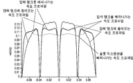
도 15은 유리 성형기(140)를 통한 용융 유리의 3D 유체 흐름 모델 속도 크기 예측을 보여준다. 흐름은 유리 성형기(140) 내에서 제1 중간 평면 및 상기 제1 중간 평면에 수직한 제2 중간 평면에 걸쳐 대칭적이므로, 상기 컴퓨터 모델의 도메인의 유리 성형기(140)의 사분의 일이다. 도시된 바와 같이, 용융 유리가 유리 성형기(140)의 측벽들과 접촉하는 곳에서 상기 용융 유리 흐름의 지역적 속도는 약 0이다. 상부 트랜지션 부재(200)에 들어가는 용융 유리는 그 중심에서 더 빠른 속도를 가진다. 또한 상부 압력 탱크 서포트(326) 및 하부 압력 탱크 서포트(336)의 영역에서 상기 용융 유리 흐름의 지역적 속도는 약 0이다. 상부 오리피스(320) 및 하부 오리피스(330)를 통한 용융 유리의 속도는 비교적 빠른 반면, 상기 용융 유리가 하부 오리피스(330)를 통해 흐르기 전에 압력 탱크 챔버(301) 내에 분배되므로 압력 탱크(300) 내에서 용융 유리의 속도는 더 느리다. 따라서, 상부 압력 탱크 서포트(326) 및/또는 하부 압력 탱크 서포트(336)를 통과한 용융 유리 흐름에 의해 야기된 임의의 용융 유리의 분리된 흐름들은 슬롯 익스텐션(400) 내에서 유리 리본(103)으로 수렴하여 융합된다. 도 15에 도시된 바와 같이, 유리 성형기(140)는 슬롯 익스텐션(400)의 단부에서 균일 속도를 가지는 유리 리본(103)을 드로우할 수 있다. 도 16에 도시된 바와 같이, 상기 슬롯 익스텐션(400)의 하단의 폭에 걸쳐 상기 용융 유리 흐름의 속도 프로파일은 플러스 마이너스 약 5%의 편차를 가진다.15 shows a 3D fluid flow model velocity magnitude prediction of the molten glass through the
도 17은 3D 콤솔 모델로 예측된, 표면 본 미제스 응력(Von Mises stress, MPa)을 설명하기 위한 유리 성형기(140)의 단면도를 보여준다. 도시된 바와 같이, 각각의 내부 구조 보강재의 높은 인장 응력에도 불구하고, 상부 트랜지션 부재 서포트(230), 상부 압력 탱크 서포트(326), 및 하부 압력 탱크 서포트(336)는 유리 성형기(140) 내의 물질 크리프를 감소시킨다.17 shows a cross-sectional view of a
특정한 실시예들의 전술한 설명은 본 발명(들)의 개괄적인 본질을 충분히 밝혀 다른 사람들이 당업계의 능력 내의 지식을 적용함으로써, 과도한 실험없이, 본 발명(들)의 개괄적인 개념으로부터 벗어나지 않고, 이러한 특정한 실시예들을 다양한 응용들을 위하여 쉽게 수정 및/또는 채택할 수 있을 것이다. 따라서, 이러한 채택들 및 수정들은 본 명세서에 나타난 교시 및 지침에 기초하여 개시된 실시예들의 균등물의 의미 및 범위 내에 속하도록 의도된다. 본 명세서의 자구 또는 용어는 설명의 목적을 위한 것이며 제한적이지 않아, 본 명세서의 용어 또는 자구는 이러한 교시들 및 지침에 비추어 통상의 기술자에 의해 해석되어야 한다는 것이 이해될 것이다.The foregoing description of certain embodiments is provided to enable any person skilled in the art to make and use the teachings of the present invention without departing from the broad concept of the invention (s), without undue experimentation, by fully understanding the general nature of the invention (s) These specific embodiments may be readily modified and / or adapted for various applications. Accordingly, these adaptations and modifications are intended to fall within the meaning and range of equivalents of the disclosed embodiments based on the teachings and guidance presented herein. It is to be understood that the phrase or terminology herein is for the purpose of description and not of limitation, that the terminology or vernacular in the specification should be interpreted by the ordinary skilled artisan in light of these teachings and guidelines.
본 개시의 폭 및 범위는 위에 기술된 예시적인 실시예들 중 어느것에 의해서도 제한되지 않아야하며, 오직 다음의 청구항들 및 그 균등문들에 따라서만 정의되어야 한다.The breadth and scope of the present disclosure should not be limited by any of the above-described exemplary embodiments, but should be defined only in accordance with the following claims and their equivalents.
Claims (31)
상기 상부 트랜지션 부재에 부착된 압력 탱크를 포함하고,
상기 압력 탱크 내의 챔버가 상기 트랜지션 챔버와 유체 상통(fluid communication)하도록 상기 압력 탱크는 상부 오리피스(orifice) 및 하부 오리피스를 포함하는 것을 특징으로 하는 유리 성형 장치.An upper transition member including a transition chamber; And
And a pressure tank attached to the upper transition member,
Wherein the pressure tank comprises an upper orifice and a lower orifice so that the chamber in the pressure tank is in fluid communication with the transition chamber.
상기 상부 오리피스에 걸쳐 위치된 상부 압력 탱크 서포트;
상기 하부 오리피스에 걸쳐 위치된 하부 압력 탱크 서포트; 및
슬롯 익스텐션의 내부 영역이 상기 압력 탱크와 유체 상통하도록 상기 압력 탱크에 부착된 상기 슬롯 익스텐션;을 더 포함하는 것을 특징으로 하는 유리 성형 장치.The method according to claim 1,
An upper pressure tank support positioned over the upper orifice;
A lower pressure tank support positioned over the lower orifice; And
Further comprising a slot extension attached to the pressure tank such that an interior region of the slot extension is in fluid communication with the pressure tank.
상기 상부 오리피스에 걸쳐 위치되는 제2 상부 압력 탱크 서포트를 더 포함하는 것을 특징으로 하는 유리 성형 장치.The method of claim 2,
Further comprising a second upper pressure tank support positioned over the upper orifice.
상기 하부 오리피스에 걸쳐 위치되는 제2 하부 압력 탱크 서포트를 더 포함하는 것을 특징으로 하는 유리 성형 장치.The method of claim 2,
And a second lower pressure tank support positioned over the lower orifice.
상기 상부 오리피스는 제1 상부 개구 및 제2 상부 개구를 포함하고,
상기 상부 압력 탱크 서포트는 상기 제1 상부 개구와 상기 제2 상부 개구 사이에 위치되고,
상기 상부 압력 탱크 서포트는 상기 압력 탱크의 벽 내에 일체로 형성되는 것을 특징으로 하는 유리 성형 장치.The method of claim 2,
Wherein the upper orifice includes a first upper opening and a second upper opening,
The upper pressure tank support being located between the first upper opening and the second upper opening,
Wherein the upper pressure tank support is integrally formed in the wall of the pressure tank.
상기 하부 오리피스는 제1 하부 개구 및 제2 하부 개구를 포함하고,
상기 하부 압력 탱크 서포트는 상기 제1 하부 개구와 상기 제2 하부 개구 사이에 위치되고,
상기 하부 압력 탱크 서포트는 상기 압력 탱크의 벽 내에 일체로 형성되는 것을 특징으로 하는 유리 성형 장치.The method of claim 2,
Wherein the lower orifice includes a first lower opening and a second lower opening,
Wherein the lower pressure tank support is located between the first lower opening and the second lower opening,
Wherein the lower pressure tank support is integrally formed in the wall of the pressure tank.
상기 장치는 열원을 포함하는 것을 특징으로 하는 유리 성형 장치.The method of claim 2,
Wherein the apparatus comprises a heat source.
상기 슬롯 익스텐션의 제1 단부는 제1 전기 커넥션을 수용하도록 구성되고, 상기 슬롯 익스텐션의 제2 단부는 제2 전기 커넥션을 수용하도록 구성되도록, 상기 열원은 상기 슬롯 익스텐션인 것을 특징으로 하는 유리 성형 장치.The method of claim 7,
Wherein the first end of the slot extension is configured to receive a first electrical connection and the second end of the slot extension is configured to receive a second electrical connection, .
상기 트랜지션 챔버에 걸쳐 위치되는 상부 트랜지션 부재 서포트를 더 포함하는 것을 특징으로 하는 유리 성형 장치.The method according to claim 1,
Further comprising an upper transition member support positioned over the transition chamber.
상기 슬롯 익스텐션의 높이는 약 18mm 내지 약 22mm 범위인 것을 특징으로 하는 유리 성형 장치.The method of claim 2,
Wherein the height of the slot extension ranges from about 18 mm to about 22 mm.
상기 압력 탱크는,
상기 압력 탱크의 제1 단부에 평행한 단부 평면을 따라 연장되는 단부 치수;
상기 압력 탱크의 상기 제1 단부와 제2 단부 사이에 연장되는 폭; 및
상기 단부 평면에 평행하고 상기 폭에 수직한 개구 방향을 따르는 개구 치수를 포함하고,
상기 압력 탱크의 내부 개구 치수는 상기 하부 오리피스의 개구 거리보다 큰 것을 특징으로 하는 유리 성형 장치.The method according to claim 1,
The pressure tank may include:
An end dimension extending along an end plane parallel to the first end of the pressure tank;
A width extending between the first end and the second end of the pressure tank; And
An opening dimension parallel to the end plane and along an opening direction perpendicular to the width,
Wherein an inner opening dimension of the pressure tank is larger than an opening distance of the lower orifice.
상기 내부 개구 치수 거리는 상기 하부 오리피스의 상기 개구 거리보다 약 2배 내지 약 10배 더 큰 범위인 것을 특징으로 하는 유리 성형 장치.The method of claim 11,
Wherein the inner opening dimension distance is in a range from about 2 times to about 10 times greater than the opening distance of the lower orifice.
상기 압력 탱크는 원통형 형상을 포함하고,
상기 압력 탱크의 종방향 축은 상기 상부 트랜지션 부재의 하단의 폭을 따라 연장되고,
상기 하부 오리피스는 폭 및 개구 거리를 가지고,
상기 압력 탱크의 직경은 상기 하부 오리피스의 상기 개구 거리보다 큰 것을 특징으로 하는 유리 성형 장치.The method according to claim 1,
Wherein the pressure tank includes a cylindrical shape,
Wherein the longitudinal axis of the pressure tank extends along the width of the lower end of the upper transition member,
The lower orifice having a width and an opening distance,
Wherein the diameter of the pressure tank is larger than the opening distance of the lower orifice.
상기 상부 트랜지션 부재는 폭을 가지는 상단을 더 포함하고,
상기 하단의 상기 폭은 상기 상단의 폭보다 큰 것을 특징으로 하는 유리 성형 장치.14. The method of claim 13,
Wherein the upper transition member further comprises a top having a width,
And the width of the lower end is larger than the width of the upper end.
상기 상단의 개구 거리는 상기 하단의 개구 거리보다 큰 것을 특징으로 하는 유리 성형 장치.15. The method of claim 14,
Wherein the upper opening distance is larger than the lower opening distance.
상기 하부 오리피스는 약 50mm 내지 약 1.5m 범위의 폭을 포함하는 것을 특징으로 하는 유리 성형 장치.The method according to claim 1,
Wherein the lower orifice comprises a width in the range of about 50 mm to about 1.5 m.
상기 하부 오리피스는 약 150mm 내지 약 300mm 범위의 폭을 포함하는 것을 특징으로 하는 유리 성형 장치.18. The method of claim 16,
Wherein the lower orifice comprises a width in the range of about 150 mm to about 300 mm.
상기 압력 탱크의 하부 오리피스를 통해 상기 용융 유리의 흐름을 통과시키는 단계를 포함하고,
상기 압력 탱크는 상기 용융 유리를 상기 압력 탱크의 중심으로부터 상기 압력 탱크의 제1 단부 및 상기 제1 단부에 대향하는 상기 압력 탱크의 제2 단부로 재분배하는 것을 특징으로 하는 유리 리본의 제조 공정.Supplying a flow of molten glass through the upper orifice of the pressure tank to the pressure tank; And
Passing a flow of the molten glass through a lower orifice of the pressure tank,
Wherein the pressure tank redistributes the molten glass from a center of the pressure tank to a first end of the pressure tank and to a second end of the pressure tank opposite the first end.
하부 압력 탱크 서포트로 상기 용융 유리를 복수의 용융 유리 흐름들로 분리시키는 단계; 및
상기 복수의 용융 유리 흐름들을 슬롯 익스텐션 내로 통과시키는 단계; 및
상기 슬롯 익스텐션으로부터 유리 리본을 드로우하는 단계를 더 포함하고,
상기 복수의 용융 유리 흐름들은 상기 슬롯 익스텐션 내에서 용융 유리의 단일한 흐름으로 수렴하여 융합하는 것을 특징으로 하는 유리 리본의 제조 공정.19. The method of claim 18,
Separating said molten glass into a plurality of molten glass flows with a lower pressure tank support; And
Passing the plurality of molten glass flows into a slotted extension; And
Further comprising drawing a glass ribbon from the slot extension,
Wherein the plurality of molten glass flows converge into a single flow of molten glass in the slotted extension to fuse.
상기 슬롯 익스텐션 내에서 상기 용융 유리의 단일한 흐름을 가열하는 단계를 더 포함하는 것을 특징으로 하는 유리 리본의 제조 공정.The method of claim 19,
Further comprising the step of heating a single flow of the molten glass within the slot extension.
상기 유리 리본을 유리 롤러 공정에 사용되는 두 롤러들 사이로 지향시키는 단계를 더 포함하는 것을 특징으로 하는 유리 리본의 제조 공정.The method of claim 19,
Further comprising the step of directing the glass ribbon between two rollers used in a glass roller process.
상기 압력 탱크는,
상기 상부 오리피스에 걸쳐 위치된 상부 압력 탱크 서포트를 더 포함하고,
상기 하부 압력 탱크 서포트는 상기 하부 오리피스에 걸쳐 위치되는 것을 특징으로 하는 유리 리본의 제조 공정.The method of claim 19,
The pressure tank may include:
Further comprising an upper pressure tank support positioned over the upper orifice,
Wherein the lower pressure tank support is positioned over the lower orifice.
상기 하부 오리피스는 제1 하부 개구 및 제2 하부 개구를 포함하고,
상기 하부 압력 탱크 서포트는 상기 제1 하부 개구와 상기 제2 하부 개구 사이에 위치되고,
상기 하부 압력 탱크 서포트는 상기 압력 탱크의 벽 내에 일체로 형성되는 것을 특징으로 하는 유리 리본의 제조 공정.23. The method of claim 22,
Wherein the lower orifice includes a first lower opening and a second lower opening,
Wherein the lower pressure tank support is located between the first lower opening and the second lower opening,
Wherein the lower pressure tank support is integrally formed in the wall of the pressure tank.
상기 슬롯 익스텐션의 높이는 약 18mm 내지 약 22mm 범위인 것을 특징으로 하는 유리 리본의 제조 공정.The method of claim 19,
Wherein the height of the slot extension ranges from about 18 mm to about 22 mm.
상기 압력 탱크는,
상기 압력 탱크의 제1 단부와 제2 단부 사이에 연장되는 폭; 및
상기 용융 유리의 유동 평면에 수직한 개구 방향을 따르는 개구 치수를 포함하고,
상기 폭은 상기 용융 유리의 상기 유동 평면에 평행한 방향을 따라 연장되고,
상기 압력 탱크의 내부 개구 치수는 상기 하부 오리피스의 개구 거리보다 더 큰 것을 특징으로 하는 유리 리본의 제조 공정.19. The method of claim 18,
The pressure tank may include:
A width extending between the first end and the second end of the pressure tank; And
And an opening dimension along an opening direction perpendicular to the flow plane of the molten glass,
The width extending along a direction parallel to the flow plane of the molten glass,
Wherein the inner opening dimension of the pressure tank is larger than the opening distance of the lower orifice.
상기 내부 개구 치수 거리는 상기 하부 오리피스의 상기 개구 거리보다 약 2배 내지 약 10배 더 큰 범위인 것을 특징으로 하는 유리 리본의 제조 공정.26. The method of claim 25,
Wherein the inner opening dimension distance is in a range from about 2 times to about 10 times greater than the opening distance of the lower orifice.
상기 압력 탱크는 원통형 형상을 포함하고,
상기 하부 오리피스는 폭 및 개구 거리를 가지고,
상기 원통의 종방향 축은 상기 압력 탱크의 상기 폭을 따라 연장되고,
상기 원통의 직경은 상기 하부 오리피스의 상기 개구 거리보다 큰 것을 특징으로 하는 유리 리본의 제조 공정.26. The method of claim 25,
Wherein the pressure tank includes a cylindrical shape,
The lower orifice having a width and an opening distance,
The longitudinal axis of the cylinder extending along the width of the pressure tank,
Wherein the diameter of the cylinder is larger than the opening distance of the lower orifice.
상기 하부 오리피스를 통한 상기 용융 유리의 유동 밀도는 시간 당 센티미터 당 약 1 킬로그램 내지 시간 당 센티미터 당 약 36 킬로그램 범위인 것을 특징으로 하는 유리 리본의 제조 공정.19. The method of claim 18,
Wherein the flow density of the molten glass through the lower orifice ranges from about 1 kilogram per centimeter per hour to about 36 kilogram per centimeter per hour.
상기 용융 유리의 점도는 대략 50 프와즈(poises) 내지 대략 20,000 프와즈인 것을 특징으로 하는 유리 리본의 제조 공정.19. The method of claim 18,
Wherein the molten glass has a viscosity of from about 50 poises to about 20,000 fwas.
상기 압력 탱크 내로 상기 용융 유리의 흐름을 공급하기 전에 상부 트랜지션 부재의 트랜지션 챔버를 통해 상기 용융 유리의 흐름을 공급하는 단계를 더 포함하고,
상기 상부 트랜지션 부재는 용융 유리 서플라이에 고정된 상단 및 상기 압력 탱크에 고정된 하단을 포함하는 것을 특징으로 하는 유리 리본의 제조 공정.19. The method of claim 18,
Further comprising feeding the flow of molten glass through a transition chamber of the upper transition member prior to feeding the flow of molten glass into the pressure tank,
Wherein the upper transition member includes an upper end fixed to the molten glass supply and a lower end fixed to the pressure tank.
상기 상부 트랜지션 부재는 상기 트랜지션 챔버에 걸쳐 위치되는 상부 트랜지션 부재 서포트를 더 포함하는 것을 특징으로 하는 유리 리본의 제조 공정.32. The method of claim 30,
Wherein the upper transition member further comprises an upper transition member support positioned over the transition chamber.
Applications Claiming Priority (3)
| Application Number | Priority Date | Filing Date | Title |
|---|---|---|---|
| US201662325672P | 2016-04-21 | 2016-04-21 | |
| US62/325,672 | 2016-04-21 | ||
| PCT/US2017/028035 WO2017184544A1 (en) | 2016-04-21 | 2017-04-18 | Method and apparatus for processing glass |
Publications (2)
| Publication Number | Publication Date |
|---|---|
| KR20180136498A true KR20180136498A (en) | 2018-12-24 |
| KR102292737B1 KR102292737B1 (en) | 2021-08-23 |
Family
ID=58664788
Family Applications (1)
| Application Number | Title | Priority Date | Filing Date |
|---|---|---|---|
| KR1020187033243A Expired - Fee Related KR102292737B1 (en) | 2016-04-21 | 2017-04-18 | Method and apparatus for processing glass |
Country Status (7)
| Country | Link |
|---|---|
| US (1) | US11180404B2 (en) |
| EP (1) | EP3445727A1 (en) |
| JP (1) | JP6929873B2 (en) |
| KR (1) | KR102292737B1 (en) |
| CN (1) | CN109071301B (en) |
| TW (1) | TWI729116B (en) |
| WO (1) | WO2017184544A1 (en) |
Cited By (1)
| Publication number | Priority date | Publication date | Assignee | Title |
|---|---|---|---|---|
| KR20190003654A (en) * | 2016-05-03 | 2019-01-09 | 코닝 인코포레이티드 | Glass Process Method and Apparatus |
Families Citing this family (13)
| Publication number | Priority date | Publication date | Assignee | Title |
|---|---|---|---|---|
| TWI729116B (en) | 2016-04-21 | 2021-06-01 | 美商康寧公司 | Methods and apparatus for processing glass |
| US12162789B2 (en) | 2018-08-10 | 2024-12-10 | Corning Incorporated | Methods and apparatus for forming laminated glass sheets |
| WO2020033387A1 (en) * | 2018-08-10 | 2020-02-13 | Corning Incorporated | Apparatus and methods for fabricating a glass ribbon |
| TWI840469B (en) | 2019-01-08 | 2024-05-01 | 美商康寧公司 | Glass manufacturing apparatus and methods |
| EP3990404A1 (en) * | 2019-06-26 | 2022-05-04 | Corning Incorporated | Apparatus for manufacturing a ribbon |
| DE102019120065A1 (en) | 2019-07-24 | 2021-01-28 | Schott Ag | Device and method for producing glass ribbons |
| DE102019120064A1 (en) * | 2019-07-24 | 2021-01-28 | Schott Ag | Device and method for producing glass ribbons |
| CN110590132B (en) * | 2019-10-22 | 2021-11-30 | 河北省沙河玻璃技术研究院 | U-shaped groove platinum-rhodium alloy bushing |
| WO2021202566A1 (en) * | 2020-03-31 | 2021-10-07 | Corning Incorporated | Method and apparatus to produce thin, perforated glass sheet |
| NL2027190B1 (en) * | 2020-11-13 | 2022-06-30 | Corning Inc | Apparatus for, and method of, roll forming sheets of high refractive index glass |
| EP4001229A3 (en) * | 2020-11-13 | 2022-08-10 | Corning Incorporated | Apparatus for, and method of, roll forming sheets of high refractive index glass |
| JP2022190511A (en) * | 2021-06-14 | 2022-12-26 | 日本電気硝子株式会社 | Molten glass supply device, and apparatus and method for manufacturing glass article |
| JP2025539376A (en) * | 2022-11-28 | 2025-12-05 | コーニング インコーポレイテッド | Apparatus and method for extracting heat during forming of glass ribbon |
Citations (2)
| Publication number | Priority date | Publication date | Assignee | Title |
|---|---|---|---|---|
| CN202808576U (en) * | 2012-07-16 | 2013-03-20 | 富荞企业管理顾问有限公司 | Pull down flat glass formers |
| JP2014094861A (en) * | 2012-11-09 | 2014-05-22 | Asahi Glass Co Ltd | Forming nozzle for plate glass |
Family Cites Families (24)
| Publication number | Priority date | Publication date | Assignee | Title |
|---|---|---|---|---|
| USRE18071E (en) * | 1931-05-19 | Apparatus for melting glass and similar substances | ||
| US1761342A (en) * | 1929-02-04 | 1930-06-03 | Pittsburgh Plate Glass Co | Apparatus for making sheet glass |
| US3149949A (en) | 1961-02-27 | 1964-09-22 | Corning Glass Works | Downflow sheet drawing method and apparatus |
| US3847585A (en) | 1973-01-08 | 1974-11-12 | Dow Chemical Co | Method for the preparation of multilayer optical filters |
| USRE31442E (en) * | 1979-12-03 | 1983-11-15 | Owens-Illinois, Inc. | Method and apparatus for manufacture of glass film |
| DE3329843A1 (en) | 1983-08-18 | 1984-01-05 | Eglasstrek Patent Promotion & Awarding GmbH, 6203 Hochheim | Process and apparatus for producing flat glass |
| DE3507852A1 (en) * | 1985-03-06 | 1985-08-08 | Diether 6500 Mainz Böttger | Device for the production of glass films |
| JP4120910B2 (en) | 1999-09-08 | 2008-07-16 | 日本電気硝子株式会社 | Method for supplying molten glass |
| TW452173U (en) | 2000-07-14 | 2001-08-21 | Lin Gang Dian | Lamp shaper structure |
| DE102004007560B4 (en) | 2004-02-17 | 2006-02-09 | Schott Ag | Device and drawing tank for the production of thin glass panes |
| CN1715225A (en) | 2004-07-02 | 2006-01-04 | 中晶光电科技股份有限公司 | Forming equipment and method for producing thin plate material by down-drawing method with narrow and long holes |
| EP1710212A1 (en) * | 2005-04-06 | 2006-10-11 | Corning Incorporated | process and device for manufacturing flat sheets of a glass-based material |
| JP2007284347A (en) | 2007-08-09 | 2007-11-01 | Nippon Electric Glass Co Ltd | Molten glass supplying device |
| US9003835B2 (en) * | 2011-05-31 | 2015-04-14 | Corning Incorporated | Precision roll forming of textured sheet glass |
| US8713972B2 (en) * | 2011-05-31 | 2014-05-06 | Corning Incorporated | Precision glass roll forming process and apparatus |
| TWM451362U (en) | 2012-07-06 | 2013-04-21 | Fu Qiao Entpr Man Consulting Co Ltd | Pull-down type flat panel glass forming machine |
| TWM452173U (en) * | 2012-07-06 | 2013-05-01 | Fu Qiao Business Man Consultants Corp | Fluid dispenser |
| US9458044B2 (en) * | 2012-07-13 | 2016-10-04 | Corning Incorporated | Methods and apparatuses for producing laminated glass sheets |
| CN202808573U (en) | 2012-07-16 | 2013-03-20 | 富荞企业管理顾问有限公司 | Flat Glass Former |
| WO2015013092A1 (en) * | 2013-07-25 | 2015-01-29 | Corning Incorporated | Methods and apparatus for forming a glass ribbon |
| KR20160063355A (en) | 2013-09-30 | 2016-06-03 | 코닝 인코포레이티드 | Apparatus and method for forming the outer layers of a glass laminate sheet |
| US10246365B2 (en) * | 2013-10-09 | 2019-04-02 | Corning Incorporated | Apparatus and method for forming thin glass articles |
| TWI729116B (en) | 2016-04-21 | 2021-06-01 | 美商康寧公司 | Methods and apparatus for processing glass |
| US12338154B2 (en) * | 2017-12-04 | 2025-06-24 | Corning Incorporated | Methods for forming thin glass sheets |
-
2017
- 2017-04-14 TW TW106112517A patent/TWI729116B/en not_active IP Right Cessation
- 2017-04-18 WO PCT/US2017/028035 patent/WO2017184544A1/en not_active Ceased
- 2017-04-18 US US16/094,955 patent/US11180404B2/en not_active Expired - Fee Related
- 2017-04-18 EP EP17720924.4A patent/EP3445727A1/en not_active Withdrawn
- 2017-04-18 JP JP2018554672A patent/JP6929873B2/en not_active Expired - Fee Related
- 2017-04-18 KR KR1020187033243A patent/KR102292737B1/en not_active Expired - Fee Related
- 2017-04-18 CN CN201780025017.4A patent/CN109071301B/en not_active Expired - Fee Related
Patent Citations (2)
| Publication number | Priority date | Publication date | Assignee | Title |
|---|---|---|---|---|
| CN202808576U (en) * | 2012-07-16 | 2013-03-20 | 富荞企业管理顾问有限公司 | Pull down flat glass formers |
| JP2014094861A (en) * | 2012-11-09 | 2014-05-22 | Asahi Glass Co Ltd | Forming nozzle for plate glass |
Cited By (1)
| Publication number | Priority date | Publication date | Assignee | Title |
|---|---|---|---|---|
| KR20190003654A (en) * | 2016-05-03 | 2019-01-09 | 코닝 인코포레이티드 | Glass Process Method and Apparatus |
Also Published As
| Publication number | Publication date |
|---|---|
| TWI729116B (en) | 2021-06-01 |
| JP2019514823A (en) | 2019-06-06 |
| CN109071301B (en) | 2022-02-01 |
| WO2017184544A1 (en) | 2017-10-26 |
| JP6929873B2 (en) | 2021-09-01 |
| KR102292737B1 (en) | 2021-08-23 |
| US11180404B2 (en) | 2021-11-23 |
| EP3445727A1 (en) | 2019-02-27 |
| TW201739709A (en) | 2017-11-16 |
| US20190152825A1 (en) | 2019-05-23 |
| CN109071301A (en) | 2018-12-21 |
Similar Documents
| Publication | Publication Date | Title |
|---|---|---|
| KR102292737B1 (en) | Method and apparatus for processing glass | |
| JP6964602B2 (en) | Methods and equipment for processing glass | |
| EP1832558B1 (en) | Plate glass manufacturing apparatus and plate glass manufacturing method | |
| JP6568598B2 (en) | Apparatus and method for processing molten material | |
| JP7796953B2 (en) | Glass manufacturing apparatus and method | |
| US10221085B2 (en) | Apparatus and methods for processing molten material | |
| CN109415235A (en) | Device and method for glass conveying orientation | |
| CN112839801B (en) | Method and apparatus for forming laminated glass sheets | |
| JP2009096684A (en) | Flow passage for flowing-out molten glass | |
| KR20160146865A (en) | Apparatus and Method of Manufacturing Composite Glass Articles | |
| KR102699833B1 (en) | Method and device for manufacturing glass articles | |
| CN119585216A (en) | Glass article manufacturing device and manufacturing method and liquid level measuring method |
Legal Events
| Date | Code | Title | Description |
|---|---|---|---|
| PA0105 | International application |
St.27 status event code: A-0-1-A10-A15-nap-PA0105 |
|
| E13-X000 | Pre-grant limitation requested |
St.27 status event code: A-2-3-E10-E13-lim-X000 |
|
| P11-X000 | Amendment of application requested |
St.27 status event code: A-2-2-P10-P11-nap-X000 |
|
| P13-X000 | Application amended |
St.27 status event code: A-2-2-P10-P13-nap-X000 |
|
| PG1501 | Laying open of application |
St.27 status event code: A-1-1-Q10-Q12-nap-PG1501 |
|
| A201 | Request for examination | ||
| PA0201 | Request for examination |
St.27 status event code: A-1-2-D10-D11-exm-PA0201 |
|
| P22-X000 | Classification modified |
St.27 status event code: A-2-2-P10-P22-nap-X000 |
|
| E902 | Notification of reason for refusal | ||
| PE0902 | Notice of grounds for rejection |
St.27 status event code: A-1-2-D10-D21-exm-PE0902 |
|
| E13-X000 | Pre-grant limitation requested |
St.27 status event code: A-2-3-E10-E13-lim-X000 |
|
| P11-X000 | Amendment of application requested |
St.27 status event code: A-2-2-P10-P11-nap-X000 |
|
| P13-X000 | Application amended |
St.27 status event code: A-2-2-P10-P13-nap-X000 |
|
| E701 | Decision to grant or registration of patent right | ||
| PE0701 | Decision of registration |
St.27 status event code: A-1-2-D10-D22-exm-PE0701 |
|
| GRNT | Written decision to grant | ||
| PR0701 | Registration of establishment |
St.27 status event code: A-2-4-F10-F11-exm-PR0701 |
|
| PR1002 | Payment of registration fee |
St.27 status event code: A-2-2-U10-U12-oth-PR1002 Fee payment year number: 1 |
|
| PG1601 | Publication of registration |
St.27 status event code: A-4-4-Q10-Q13-nap-PG1601 |
|
| PC1903 | Unpaid annual fee |
St.27 status event code: A-4-4-U10-U13-oth-PC1903 Not in force date: 20240818 Payment event data comment text: Termination Category : DEFAULT_OF_REGISTRATION_FEE |
|
| PC1903 | Unpaid annual fee |
St.27 status event code: N-4-6-H10-H13-oth-PC1903 Ip right cessation event data comment text: Termination Category : DEFAULT_OF_REGISTRATION_FEE Not in force date: 20240818 |