KR20180107445A - Vegetable Storage Box Carrying Apparatus - Google Patents
Vegetable Storage Box Carrying Apparatus Download PDFInfo
- Publication number
- KR20180107445A KR20180107445A KR1020170035612A KR20170035612A KR20180107445A KR 20180107445 A KR20180107445 A KR 20180107445A KR 1020170035612 A KR1020170035612 A KR 1020170035612A KR 20170035612 A KR20170035612 A KR 20170035612A KR 20180107445 A KR20180107445 A KR 20180107445A
- Authority
- KR
- South Korea
- Prior art keywords
- box
- base
- tray
- pallet
- conveyer
- Prior art date
Links
Images


Classifications
-
- B—PERFORMING OPERATIONS; TRANSPORTING
- B65—CONVEYING; PACKING; STORING; HANDLING THIN OR FILAMENTARY MATERIAL
- B65G—TRANSPORT OR STORAGE DEVICES, e.g. CONVEYORS FOR LOADING OR TIPPING, SHOP CONVEYOR SYSTEMS OR PNEUMATIC TUBE CONVEYORS
- B65G37/00—Combinations of mechanical conveyors of the same kind, or of different kinds, of interest apart from their application in particular machines or use in particular manufacturing processes
-
- B—PERFORMING OPERATIONS; TRANSPORTING
- B65—CONVEYING; PACKING; STORING; HANDLING THIN OR FILAMENTARY MATERIAL
- B65G—TRANSPORT OR STORAGE DEVICES, e.g. CONVEYORS FOR LOADING OR TIPPING, SHOP CONVEYOR SYSTEMS OR PNEUMATIC TUBE CONVEYORS
- B65G13/00—Roller-ways
-
- B—PERFORMING OPERATIONS; TRANSPORTING
- B65—CONVEYING; PACKING; STORING; HANDLING THIN OR FILAMENTARY MATERIAL
- B65G—TRANSPORT OR STORAGE DEVICES, e.g. CONVEYORS FOR LOADING OR TIPPING, SHOP CONVEYOR SYSTEMS OR PNEUMATIC TUBE CONVEYORS
- B65G47/00—Article or material-handling devices associated with conveyors; Methods employing such devices
- B65G47/74—Feeding, transfer, or discharging devices of particular kinds or types
- B65G47/82—Rotary or reciprocating members for direct action on articles or materials, e.g. pushers, rakes, shovels
-
- B—PERFORMING OPERATIONS; TRANSPORTING
- B65—CONVEYING; PACKING; STORING; HANDLING THIN OR FILAMENTARY MATERIAL
- B65G—TRANSPORT OR STORAGE DEVICES, e.g. CONVEYORS FOR LOADING OR TIPPING, SHOP CONVEYOR SYSTEMS OR PNEUMATIC TUBE CONVEYORS
- B65G59/00—De-stacking of articles
- B65G59/02—De-stacking from the top of the stack
- B65G59/026—De-stacking from the top of the stack with a stepwise upward movement of the stack
-
- B—PERFORMING OPERATIONS; TRANSPORTING
- B65—CONVEYING; PACKING; STORING; HANDLING THIN OR FILAMENTARY MATERIAL
- B65G—TRANSPORT OR STORAGE DEVICES, e.g. CONVEYORS FOR LOADING OR TIPPING, SHOP CONVEYOR SYSTEMS OR PNEUMATIC TUBE CONVEYORS
- B65G2201/00—Indexing codes relating to handling devices, e.g. conveyors, characterised by the type of product or load being conveyed or handled
- B65G2201/02—Articles
- B65G2201/0202—Agricultural and processed food products
- B65G2201/0211—Fruits and vegetables
-
- B—PERFORMING OPERATIONS; TRANSPORTING
- B65—CONVEYING; PACKING; STORING; HANDLING THIN OR FILAMENTARY MATERIAL
- B65G—TRANSPORT OR STORAGE DEVICES, e.g. CONVEYORS FOR LOADING OR TIPPING, SHOP CONVEYOR SYSTEMS OR PNEUMATIC TUBE CONVEYORS
- B65G2201/00—Indexing codes relating to handling devices, e.g. conveyors, characterised by the type of product or load being conveyed or handled
- B65G2201/02—Articles
- B65G2201/0235—Containers
- B65G2201/025—Boxes
-
- B—PERFORMING OPERATIONS; TRANSPORTING
- B65—CONVEYING; PACKING; STORING; HANDLING THIN OR FILAMENTARY MATERIAL
- B65G—TRANSPORT OR STORAGE DEVICES, e.g. CONVEYORS FOR LOADING OR TIPPING, SHOP CONVEYOR SYSTEMS OR PNEUMATIC TUBE CONVEYORS
- B65G2207/00—Indexing codes relating to constructional details, configuration and additional features of a handling device, e.g. Conveyors
- B65G2207/14—Combination of conveyors
Abstract
Description
본 발명은 야채 수납 박스 운반장치에 관한 것으로, 더욱 상세하게는 배추, 무 등의 야채를 담은 박스를 일정 단위로 이송한 후 내용물을 꺼내고 빈 박스를 수거하는 과정이 자동으로 연속 수행될 수 있도록 하는 야채 수납 박스 운반장치에 관한 것이다.BACKGROUND OF THE INVENTION 1. Field of the Invention [0001] The present invention relates to a vegetable storage box transporting apparatus, and more particularly, to a vegetable storage box transporting apparatus that transports a box containing vegetables such as Chinese cabbage and radishes, To a vegetable storage box carrying device.
일반적으로 배추, 무 등의 야채는 산지에서 일정 수량씩 박스에 담아 트럭으로 운반하여 김치공장 등으로 공급된다. Generally, vegetables such as cabbage, radish, etc. are packed in a box in a certain quantity in a mountain area and transported to a kimchi factory.
배추 등 채소의 잎이 여러 겹으로 이루어진 채소는 비교적 부피가 크고 수확시 손상되기 쉬워 밭에서부터 박스에 담아 트럭에 적재하여 출하하고 있는 실정이다. Vegetables made of multiple layers of leaf, such as Chinese cabbage, are relatively bulky and easily damaged when harvested, so they are shipped from the field into a truck and loaded into a truck.
대형 트럭으로부터 박스 단위로 하차된 야채 수납 박스를 작업자가 운반하여 내용물을 쏟아낸 후 빈 박스를 수거하는 작업을 수작업으로 수행하고 있었는 바 작업 인원이 많이 소요되고, 시간이 오래 걸리므로 작업 능률이 낮은 반면 인건비 등의 비용은 상승하는 부담이 있었다. Since the operator carried the vegetable storage box, which was taken out of the large truck, in a box unit, the contents were poured out and the empty box was collected by hand, the number of workers was large and the operation efficiency was low On the other hand, expenses such as labor costs were burdened.
본 발명은 상기한 종래 기술의 문제점을 해소하기 위해 안출된 것으로, 배추, 무 등의 야채를 담은 박스를 일정 단위로 이송한 후 내용물을 꺼내고 빈 박스를 수거하는 과정이 자동으로 연속 수행될 수 있도록 하는 야채 수납 박스 운반장치를 제공하는데 그 목적이 있다.DISCLOSURE OF THE INVENTION The present invention is conceived to solve the problems of the prior art described above, and it is an object of the present invention to provide a method and apparatus for automatically transporting a box containing vegetables such as Chinese cabbage, radish, etc., The present invention has been made to provide a vegetable storage box conveying device.
상기한 본 발명의 목적은, 지면에 하단이 지지되고 일정 높이를 갖도록 형성된 기대; 상기 기대의 일측에 형성되며, 야채를 담은 박스를 다층으로 적재하는 파레트와, 파레트를 상승시키는 리프팅장치를 구비한 파레트 콘베어: 파레트 콘베어의 상부에 배치되며, 파레트 콘베어에 안착된 박스에 밀착되는 박스홀딩장치와, 박스를 승강시키는 박스상승장치로 구성되는 협지장치; 기대의 상부에 형성되며, 상기 협지장치를 수평이동시키는 이동레일부; 기대의 상부에 형성되며, 이동레일부의 하부에 형성되며 협지장치로부터 분리된 박스를 안착시킨 후 이송하는 1차 콘베어장치; 기대의 상부에 형성되며, 1차 콘베어장치에 연결되며 하향경사지게 배치되어 박스를 하향 이동시키는 2차 콘베어장치; 상기 2차 콘베어장치의 말단부에 형성되며 박스를 수납하며 회전구동하는 트레이와, 트레이를 회전시켜 배추를 쏟아내는 구동부를 구비한 박스회전장치; 상기 2차 콘베어장치의 단부와 회전장치의 하부에 형성되어 배추를 이송하는 배출 콘베어; 상기 2차 콘베어장치의 하부에 형성되며 회전된 트레이의 박스를 밀어 취출시키는 취출장치; 취출된 박스를 수거하는 빈박스 수거장치;를 포함하는 야채 수납 박스 운반장치에 의해 달성될 수 있다. SUMMARY OF THE INVENTION The object of the present invention is to provide an apparatus and a method for mounting a substrate on a substrate. A pallet which is formed on one side of the base and carries a pallet for stacking a box containing vegetables therein and a lifting device for lifting the pallet; a pallet conveyor disposed on the pallet conveyor, A holding device comprising a holding device and a box raising device for raising and lowering the box; A movable rail part formed on the upper side of the base and horizontally moving the nipping device; A primary conveyor device formed at the upper part of the base and formed at the lower part of the movable rail part and having a box separated from the nipping device placed thereon and then conveyed; A secondary conveyor device formed at the top of the base and connected to the primary conveyor device and disposed downwardly inclined to move the box downward; A box rotating device formed at a distal end of the secondary conveyor device and having a tray for receiving and rotating the box and a driving part for rotating the tray to pour out the cabbage; A discharge conveyor formed at an end of the secondary conveyor apparatus and a lower portion of the rotary apparatus for conveying the Chinese cabbage; A take-out device formed at a lower portion of the secondary conveyor device and pushing out a box of the rotated tray; And an empty box collection device for collecting the extracted box.
상기 협지장치는 수직하게 형성되며, 통공이 형성되어 양측에 평행하게 배치된 측판과, 상기 양 측판의 상단을 연결하는 바로 구성된 본체; 상기 측판의 내면에 수직하게 형성되는 가이드레일; 상기 가이드레일에 결합되어 상하방향으로 슬라이딩되는 브라켓;을 포함하고, 상기 박스홀딩장치는, 상기 측판의 통공을 관통하여 결합되며 수평하게 설치되며, 브라켓의 측면에 결합되고, 상기 박스상승장치는, 브라켓의 상부에 결합되며 수직하게 설치되어 브라켓 및 박스홀딩장치를 상승 또는 하강시키도록 하는 것을 특징으로 한다. The nipping device includes a side plate formed vertically and arranged parallel to both sides of the through hole, and a body configured to connect upper ends of the side plates; A guide rail vertically formed on the inner surface of the side plate; And a box lifting device coupled to the side surface of the bracket, the box lifting device being coupled to the guide rail and slidable in a vertical direction, And is vertically installed to be coupled to an upper portion of the bracket so as to raise or lower the bracket and the box holding device.
상기 박스홀딩장치는 박스의 측면을 협지하는 지지판과, 상기 지지판이 부착되어 출몰작동하는 실린더로드를 갖는 제1실린더유닛;을 포함하는 것을 특징으로 한다. The box holding apparatus includes a first cylinder unit having a support plate for holding a side surface of a box, and a cylinder rod to which the support plate is attached and operates.
상기 박스상승장치는 브라켓의 상부에 결합되며 출몰작동하는 실린더로드와, 실린더로드가 구비되며 측판의 내면에 형성된 장착대에 설치된 제2실린더유닛으로 구성되는 것을 특징으로 한다. The box lifter comprises a cylinder rod coupled to an upper portion of a bracket and projecting and retracting, and a second cylinder unit having a cylinder rod and provided on a mounting table formed on the inner surface of the side plate.
상기 이동레일부는 기대의 상부에 수평하게 형성된 수평프레임의 상면에 길이방향으로 수평하게 형성되는 레일과, 상기 레일에 결합되도록 협지장치의 측판에 부착된 외판의 내측에 형성된 롤러부재; 상기 수평프레임의 단부에 형성되며 협지장치를 레일을 따라 이동시키는 박스이송장치;를 포함하는 것을 특징으로 한다. The moving rail portion includes a rail formed horizontally in the longitudinal direction on the upper surface of a horizontal frame formed horizontally above the base, a roller member formed inside the outer plate attached to the side plate of the nip device to be coupled to the rail, And a box transporting device formed at an end of the horizontal frame and moving the nipping device along the rails.
상기 박스이송장치는 상기 레일의 일단부에 구비되는 모터와, 모터에 연결되어 회전하는 풀리와, 풀리에 권취되고 협지장치의 본체와 연결되는 체인으로 구성되는 것을 특징으로 한다. The box transporting device is comprised of a motor provided at one end of the rail, a pulley connected to the motor and rotated, and a chain wound around the pulley and connected to the main body of the nipping device.
상기 박스회전장치의 트레이는 수직 프레임과 수평프레임이 연결되어 'ㄴ'자 형상으로 형성되며 복수개로 구성된 가로부재와, 복수개의 가로부재를 연결하는 세로부재로 이루어져 박스가 수용될 수 있고 뒤집어져도 이탈되지 않도록 형성된 것이며, 수평프레임의 단부 외측에 회전축이 형성되고, 상기 회전축은 기대의 일측에 베어링으로 연결되어 이루어진 것을 특징으로 한다. The tray of the box rotating device is composed of a horizontal member formed by connecting a vertical frame and a horizontal frame to form an 'B' shape, a plurality of horizontal members, and a vertical member connecting the plurality of horizontal members, And a rotary shaft is formed outside the end of the horizontal frame, and the rotary shaft is connected to one side of the base by a bearing.
상기 박스회전장치의 구동부는 상기 트레이의 회전축에 형성된 피니언기어; 상기 피니언기어에 치차결합되며 수직하게 형성된 랙기어; 상기 랙기어의 하단에 로드가 연결되고 상기 로드를 승강작동시켜 피니언기어 및 트레이를 회전시키는 구동유닛;을 포함하는 것을 특징으로 한다. The driving unit of the box rotating device includes: a pinion gear formed on a rotary shaft of the tray; A rack gear which is gear-engaged with the pinion gear and formed vertically; And a driving unit connected to a lower end of the rack gear and for raising and lowering the rod to rotate the pinion gear and the tray.
상기 취출장치는 2차 콘베어장치의 하부에 수평되게 장착되는 실린더 몸체와, 상기 실린더 몸체로부터 출몰작동되는 실린더로드로 구성되고, 실린더로드의 단부에는 박스에 접촉되는 플레이트가 형성되어 이루어진 것을 특징으로 한다. The take-out device is constituted by a cylinder body horizontally mounted on the lower part of the secondary conveyor device and a cylinder rod operated to protrude and retract from the cylinder body, and a plate contacting the box is formed at the end of the cylinder rod .
본 발명에 따르면, 배추, 무 등의 야채를 담은 박스를 일정 단위로 이송한 후 내용물을 꺼내고 빈 박스를 수거하는 과정이 자동으로 연속 수행될 수 있어 야채의 손상을 최소화할 수 있고, 작업 비용을 절감할 수 있으며 작업 능률이 월등히 향상될 수 있는 효과가 있다. According to the present invention, it is possible to automatically carry out a process of transporting a box containing vegetables such as Chinese cabbage and radishes in a predetermined unit and then taking out the contents and collecting the empty box, thereby minimizing the damage of vegetables, And the work efficiency can be greatly improved.
도 1은 본 발명에 따른 야채 수납 박스 운반장치를 나타낸 사시도,
도 2는 본 발명에 따른 야채 수납 박스 운반장치를 나타낸 정면도,
도 3은 본 발명에 따른 야채 수납 박스 운반장치를 나타낸 평면도,
도 4는 본 발명에 따른 야채 수납 박스 운반장치를 나타낸 측면도,
도 5 내지 도 7은 본 발명에 따른 야채 수납 박스 운반장치에서 '취출장치'의 작동을 순서대로 예시한 확대도,
도 8 내지 도 10은 본 발명에 따른 야채 수납 박스 운반장치에서 '협지장치'의 작동을 순서대로 예시한 확대도.1 is a perspective view of a vegetable storage box carrying apparatus according to the present invention;
FIG. 2 is a front view showing a vegetable storage box transporting apparatus according to the present invention. FIG.
FIG. 3 is a plan view of a vegetable storage box transporting apparatus according to the present invention,
FIG. 4 is a side view showing a vegetable storage box transporting apparatus according to the present invention,
5 to 7 are enlarged views sequentially illustrating the operation of the 'takeout apparatus' in the vegetable storage box transporting apparatus according to the present invention,
8 to 10 are enlarged views sequentially illustrating the operation of the 'nipping device' in the vegetable storage box transporting device according to the present invention.
이하 본 발명의 바람직한 실시예를 첨부된 도면을 토대로 상세하게 설명하면 다음과 같다.Hereinafter, preferred embodiments of the present invention will be described in detail with reference to the accompanying drawings.
후술하는 용어들은 본 발명에서의 기능을 고려하여 정의된 것으로서, 이는 본 발명의 기술적 사상에 부합하는 개념과 당해 기술분야에서 통용 또는 통상적으로 인식되는 의미로 해석되어야 함을 명시한다.The following terms are defined in consideration of the functions of the present invention, and they are to be construed to mean concepts that are consistent with the technical idea of the present invention and interpretations that are commonly or commonly understood in the technical field.
또한, 본 발명과 관련된 공지기능 혹은 구성에 대한 구체적인 설명이 본 발명의 요지를 흐릴 수 있다고 판단되는 경우 그 상세한 설명은 생략한다.In the following description, well-known functions or constructions are not described in detail to avoid obscuring the subject matter of the present invention.
여기서, 첨부된 도면들은 기술의 구성 및 작용에 대한 설명과 이해의 편의 및 명확성을 위해 일부분을 과장하거나 간략화하여 도시한 것으로서, 각 구성요소가 실제의 크기와 정확하게 일치하는 것은 아니다.Here, the attached drawings are exaggerated or simplified in order to facilitate understanding and clarification of the structure and operation of the technology, and the components do not exactly coincide with actual sizes.
첨부된 도면 중에서, 도 1은 본 발명에 따른 야채 수납 박스 운반장치를 나타낸 사시도, 도 2는 본 발명에 따른 야채 수납 박스 운반장치를 나타낸 정면도, 도 3은 본 발명에 따른 야채 수납 박스 운반장치를 나타낸 평면도, 도 4는 본 발명에 따른 야채 수납 박스 운반장치를 나타낸 측면도, 도 5 내지 도 7은 본 발명에 따른 야채 수납 박스 운반장치에서 '취출장치'의 작동을 순서대로 예시한 확대도, 도 8 내지 도 10은 본 발명에 따른 야채 수납 박스 운반장치에서 '협지장치'의 작동을 순서대로 예시한 확대도이다.1 is a perspective view of a vegetable storage box transporting apparatus according to the present invention, FIG. 2 is a front view showing a vegetable storage box transporting apparatus according to the present invention, and FIG. 3 is a front view of the vegetable storage box transporting apparatus according to the present invention. 5 to 7 are enlarged views sequentially illustrating the operation of the 'takeout apparatus' in the vegetable storage box transporting apparatus according to the present invention, FIG. 4 is a side view showing the vegetable storage box transporting apparatus according to the present invention, 8 to 10 are enlarged views sequentially illustrating the operation of the 'nipping device' in the vegetable storage box transporting device according to the present invention.
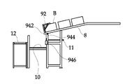
도 1 내지 도 10에 나타낸 바와 같이, 본 발명에 따른 야채 수납 박스 운반장치는, 지면에 하단이 지지되고 일정 높이를 갖도록 형성된 기대(2); 상기 기대(2)의 일측에 형성되며, 야채를 담은 박스(B)를 다층으로 적재하는 파레트(P)와, 파레트(P)를 상승시키는 리프팅장치(32)를 구비한 파레트 콘베어(3): 파레트 콘베어(3)의 상부에 배치되며, 파레트 콘베어(3)에 안착된 박스(B)에 밀착되는 박스홀딩장치(52)와, 박스(B)를 승강시키는 박스상승장치(54)로 구성되는 협지장치(5); 기대(2)의 상부에 형성되며, 상기 협지장치(5)를 수평이동시키는 이동레일부(6); 기대(2)의 상부에 형성되며, 이동레일부(6)의 하부에 형성되며 협지장치(5)로부터 분리된 박스(B)를 안착시킨 후 이송하는 1차 콘베어장치(7); 기대(2)의 상부에 형성되며, 1차 콘베어장치(7)에 연결되며 하향경사지게 배치되어 박스(B)를 하향 이동시키는 2차 콘베어장치(8); 상기 2차 콘베어장치(8)의 말단부에 형성되며 박스(B)를 수납하며 회전구동하는 트레이(92)와, 트레이(92)를 회전시켜 야채를 쏟아내는 구동부(94)를 구비한 박스회전장치(9); 상기 2차 콘베어장치(8)의 단부와 회전장치의 하부에 형성되어 야채를 이송하는 배출 콘베어(10); 상기 2차 콘베어장치(8)의 하부에 형성되며 회전된 트레이(92)의 박스(B)를 밀어 취출시키는 취출장치(11); 취출된 박스(B)를 수거하는 빈박스 수거장치(12);를 포함하여 구성된다. 1 to 10, a vegetable storage box transporting apparatus according to the present invention includes: a
상기 기대(2)는 지면에 수직하게 설치되는 수직빔(22)과, 수직빔(22)의 상부에 수평 및 경사지게 설치되는 상부빔(24)으로 구성되며, 상부빔(24)은 수평의 1차 콘베어장치(7)와, 경사진 2차 콘베어장치(8)가 설치된다. The
기대(2)의 일측 단부에는 파레트 콘베어(3)가 배치되고, 타측 단부에는 박스회전장치(9)로부터 탈거되는 박스(B) 및 야채를 수용하도록 각기 배출 콘베어(10)와 빈박스 수거장치(12)가 구비된다. A
빈박스 수거장치(12)는 콘베어벨트이며, 외부의 작업자가 빈박스를 수거하기 용이하도록 이송하게 된다. The empty
상기 파레트 콘베어(3)는 다수의 링크편(322)이 X자형태로 힌지 결합되어 있어 접철작동되게 구비되고, 링크편(322)을 접철시키는 유압모터로 구성되는 리프팅장치(32)가 구비되며, 상부에 파레트(P)를 안착하기 위한 콘베어벨트가 형성되어 이루어진다. The
센서는 상층부의 박스(B)가 한층씩 배출될때마다 유압모터를 작동시켜 링크편(322)을 전개하여 파레트(P) 및 그에 안착된 박스(B)를 점차 상승시키게 된다. The sensor operates the hydraulic motor every time the box B in the upper layer is discharged one by one to expand the
상기 리프팅장치(32)의 일측에는 복수의 파레트 콘베어(3)가 직렬 배치되고, 각 파레트 콘베어(3)에는 다수의 박스(B)가 적재됨으로써 앞쪽 파레트 콘베어(3)의 박스(B)가 소진되면 뒷쪽 파레트 콘베어(3-2,3-3)의 박스(B)가 이동되어 연속 공급이 가능해진다. A plurality of
리프팅장치(32)의 타측에는 빈 파레트(P)를 배출하는 취출콘베어(3-5)가 형성된다. On the other side of the
파레트 콘베어(3)의 상부에는 상층부의 박스(B)를 들어올릴 수 있도록 협지장치(5)가 구비된다. A
협지장치(5)는 박스(B)의 측면에 밀착되는 박스홀딩장치(52)와, 박스(B)를 승강시키는 박스상승장치(54)로 구성된다. The
상기 협지장치(5)는 수직하게 형성되며, 통공(513)이 형성되어 양측에 평행하게 배치된 측판(512)과, 상기 양 측판(512)의 상단을 연결하는 바(519)로 구성된 본체(51); 상기 측판(512)의 내면에 수직하게 형성되는 가이드레일(63); 상기 가이드레일(63)에 결합되어 상하방향으로 슬라이딩되는 브라켓(55);을 포함하여 구성된다. The
상기 박스홀딩장치(52)는, 상기 측판(512)의 통공(513)을 관통하여 결합되며 수평하게 설치되며, 브라켓(55)의 측면에 결합되는 것으로, 박스(B)의 측면을 협지하는 지지판(C1-1)과, 상기 지지판(C1-1)이 부착되어 출몰작동하는 실린더로드(C1-2)를 갖는 제1실린더유닛(C1);으로 구성된다. The
상기 박스상승장치(54)는, 브라켓(55)의 상부에 결합되며 수직하게 설치되어 브라켓(55) 및 박스홀딩장치(52)를 상승 또는 하강시키도록 하는 것이다. The
상기 박스상승장치(54)는 브라켓(55)의 상부에 결합되며 출몰작동하는 실린더로드(C2-2)와, 실린더로드(C2-2)가 구비되며 측판(512)의 내면에 형성된 장착대(514)에 설치된 제2실린더유닛(C2)으로 구성되며, 상기 측판(512)의 내측 상부에 수직하게 장착되고 상기 제1실린더유닛(C1)을 승강시키는 작동을 하게 된다. The
상기 이동레일부(6)는 기대(2)의 상부빔(24)에 수평하게 형성된 수평프레임(58)의 상면에 길이방향으로 수평하게 형성되는 레일(63)과, 상기 레일(63)에 결합되도록 협지장치(5)의 측판(512)에 부착된 외판(57)의 내측에 형성된 롤러부재(66);를 포함하고, 상기 수평프레임(58)의 단부에 형성되며 협지장치(5)를 레일(63)을 따라 이동시키는 박스이송장치(59);를 포함하여 구성된다. The moving
박스이송장치(59)는 협지장치(5)를 수평방향으로 이동시켜 박스(B)를 1차 콘베어장치(7)로 이동시킨 후 다시 원래 상태로 복귀하는 작동을 하게 된다.The
일 형태에 따르면, 상기 박스이송장치(59)는 상기 레일(63)의 일단부에 구비되는 모터와, 모터에 연결되어 회전하는 풀리와, 풀리에 권취되고 협지장치(5)의 본체(51)와 연결되는 체인으로 구성될수 있다.The
다른 형태에 따르면, 상기 박스이송장치(59)는 롤러부재(66)에 구동장치가 포함되고, 구동장치의 구동에 의해 롤러부재(66)가 레일(63)을 주행하도록 한 것이다.According to another aspect of the present invention, the
박스이송장치(59)의 수평방향 구동을 유발하는 구동수단은 보다 다양하게 변형 실시될 수 있으며, 이러한 구동수단도 모두 본 발명의 범주 내에 속하는 것으로 보아야할 것이다. The driving means for causing the horizontal movement of the
도 8을 참조하면, 박스홀딩장치(52)를 구성하는 제1실린더유닛(C1)의 실린더로드(C1-2) 및 지지판(C1-1)이 후퇴하여 박스(B)로부터 이격된다.Referring to Fig. 8, the cylinder rod C1-2 and the support plate C1-1 of the first cylinder unit C1 constituting the
도 9를 참조하면, 박스홀딩장치(52)의 실린더로드(C1-2) 및 지지판(C1-1)이 전진하여 박스(B)의 측면에 밀착된다. Referring to Fig. 9, the cylinder rod C1-2 and the support plate C1-1 of the box-
도 10을 참조하면, 박스홀딩장치(52)의 지지판(C1-1)이 박스(B)의 측면에 밀착된 상태에서 박스상승장치(54)가 구동되어 제1실린더유닛(C1)을 상승시킴으로써 박스(B)도 동반하여 상승시키게 된다. 10, the
이후 이동레일부(6)를 타고 협지장치(5)가 이동된 후 박스홀딩장치(52)가 작동되어 지지판(C1-1)이 후퇴하여 박스(B)로부터 이격됨으로써 박스(B)를 1차 콘베어장치(7)에 올려놓게 된다. The
상기 1차 콘베어장치(7)는 기대(2)의 상부빔에 형성되며, 이동레일부(6)의 하부에 형성되고, 양측 상부빔(24)에 다수의 롤러(72)가 병렬 배치되게 결합되어 이루어진 것으로, 협지장치(5)로부터 분리된 박스(B)가 다수의 롤러(72)에 안착된 후 이송된다. The
상기 2차 콘베어장치(8)는 1차 콘베어장치(7)에 연결되며 기대(2)의 상부에 경사지게 형성된 양측 상부빔(24)에 다수의 롤러(72)가 병렬 배치되어 이루어진 것으로, 하향경사지게 형성됨으로써 롤러(72)를 타고 이동하는 박스(B)가 하방으로 이동하게 된다. The
2차 콘베어장치(8)를 타고 박스(B)가 이동된 후 박스회전장치(9)의 트레이(92)에 박스(B)가 수납된다. The box B is housed in the
상기 트레이(92)는 수직 프레임(921)과 수평프레임(922)이 연결되어 'ㄴ'자 형상으로 형성되며 복수개로 구성된 가로부재(923)와, 복수개의 가로부재(923)를 연결하는 세로부재로 이루어져 박스(B)가 수용될 수 있고 뒤집어져도 이탈되지 않도록 형성된 것이다. The
트레이(92)의 수평프레임(58)의 단부 외측에 회전축이 형성되고, 회전축은 2차 콘베어장치(8)의 단부 기대에 형성된 베어링박스(B)에 결합되어 트레이(92)는 대략 180°의 회전 각도를 갖도록 회전범위가 설정된다. A rotary shaft is formed outside the end of the
따라서 트레이(92)의 수직 프레임(921)이 수직하게 배치되어 박스(B)를 향해 개구부가 향하도록 하는 대기상태와, 박스(B)가 수납된 후 하방으로 180°회전함으로써 박스(B)를 뒤집어줌으로써 내용물이 배출 콘베어(10)로 쏟아져 배출되도록 한다. The
한편 트레이(92)의 상부를 덮도록 커버(97)가 장착되고, 커버(97)는 개폐작동되도록 일측에 개폐실린더(972)가 형성된다. On the other hand, a cover 97 is mounted to cover the upper portion of the
커버(97)의 일측 전면부는 박스(B)가 통과될 수 있도록 개방되어 있고, 타측 후면부는 기대(2)에 힌지 결합되고, 개폐실린더(92)는 기대에 장착되어 커버(97)를 열거나 닫을 수 있다. One side of the cover 97 is opened to allow the box B to pass therethrough and the other side of the cover 97 is hinged to the
트레이(92)를 회전시키는 작동을 하는 동안에는 커버(97)를 닫아줌으로써 트레이(92)의 회전작동 과정에서 내용물이 외부로 쏟아지지 않도록 보호하게 된다. During the operation of rotating the
상기 박스회전장치(9)의 구동부(94)는 상기 트레이(92)의 회전축에 형성된 피니언기어(942); 상기 피니언기어(942)에 치차결합되며 수직하게 형성된 랙기어(944); 상기 랙기어(944)의 하단에 로드가 연결되고 상기 로드를 승강작동시켜 피니언기어(942) 및 트레이(92)를 회전시키는 구동유닛(946);을 포함하여 구성된다. The driving
구동유닛(946)은 유압실린더, 공압실린더 또는 전동모터가 적용될 수 있다. The
도 5 및 도 6을 참조하면, 로드 및 랙기어(944)가 수직방향으로 상승하면 피니언기어(942)가 회전되어 트레이(92)를 배출 콘베어(10)를 향해 뒤집어 회전시키는 구동을 하게 된다. 5 and 6, when the rod and the
트레이(92)가 뒤집어지면 내부의 박스(B)도 뒤집어지게 되므로 트레이(92)의 상부 개구부를 통해 박스(B) 내의 내용물이 쏟아져서 배출된다.When the
배출된 내용물은 배출 콘베어(10)를 타고 이송되어 후가공 작업장으로 이송될 것이다. The discharged contents will be conveyed on the
이후 도 7을 참조하면, 트레이(92)의 일측에 구비된 취출장치(11)가 작동되어 빈박스를 외측으로 배출시킨다. Referring to FIG. 7, the take-out
이후 박스(B)의 내용물 배출 및 빈박스의 취출이 완료된 후 로드가 수직방향으로 하강하면 피니언기어(942)가 역회전되어 트레이(92)를 상방으로 회전시켜 2차 콘베어장치(8)로부터 내용물이 담긴 박스(B)를 수납할 수 있도록 대기 상태가 된다. After the contents are discharged from the box B and the empty box is completely taken out, the
한편 상술한 바와 같이, 트레이(92)를 배출 콘베어(10)를 향해 뒤집어 회전시키는 구동을 한 후 트레이(92) 내부의 박스(B)를 밀어 빈박스 수거장치(12)로 배출하도록 취출장치(11)가 작동된다. As described above, after the
상기 취출장치(11)는 2차 콘베어장치(8)의 하부에 수평되게 장착되는 실린더 몸체(112)와, 상기 실린더 몸체(112)로부터 출몰작동되는 실린더로드로 구성되고, 실린더로드의 단부에는 박스에 접촉되는 플레이트(114)를 포함하여 이루어진다.The take-out
플레이트(114)는 트레이(92)의 가로부재 및 세로부재 사이의 공간을 통과하여 전후진 작동되며, 트레이(92)의 상부는 개방되어 있으므로 트레이(92)가 뒤집어지면 상부를 통해 내용물이 배출되고, 박스(B)는 뒤집어진 상태에 있고, 취출장치(11)의 실린더로드가 전진하여 박스(B)를 밀어냄으로써 트레이(92)로부터 박스(B)를 배출시키게 된다. The
배출된 빈박스는 빈박스 수거장치(12)로 이송되고, 이후 빈박스만 모아 재활용하게 된다. The discharged empty box is transferred to the empty
본 발명은 상술한 실시 예 및 첨부된 도면에 의해 한정되는 것이 아니고, 본 발명의 기술적 사상을 벗어나지 않는 범위 안에서 예시되지 않은 여러 가지 변형과 응용이 가능함은 물론 구성요소의 치환 및 균등한 타실시 예로 변경할 수 있으므로 본 발명의 특징에 대한 변형과 응용에 관계된 내용은 본 발명의 범위 내에 포함되는 것으로 해석되어야 할 것이다.It is to be understood that the present invention is not limited to the above-described embodiment and the accompanying drawings, and that various changes and modifications may be made without departing from the scope of the present invention, It will be understood by those skilled in the art that various changes in form and details may be made therein without departing from the spirit and scope of the invention as defined by the appended claims.
2 : 기대 3 : 파레트 콘베어
5 : 협지장치 6 : 이동레일부
7 : 1차 콘베어장치 8 : 2차 콘베어장치
9 : 박스회전장치 10 : 배출 콘베어
11 : 취출장치 12 : 빈박스 수거장치2: Expectation 3: pallet conveyor
5: Nipping device 6: Movable rail part
7: Primary conveyor device 8: Secondary conveyor device
9: Box rotating device 10: Discharge conveyor
11: take-out device 12: empty box collecting device
Claims (9)
상기 기대의 일측에 형성되며, 야채를 담은 박스를 다층으로 적재하는 파레트와, 파레트를 상승시키는 리프팅장치를 구비한 파레트 콘베어:
파레트 콘베어의 상부에 배치되며, 파레트 콘베어에 안착된 박스에 밀착되는 박스홀딩장치와, 박스를 승강시키는 박스상승장치로 구성되는 협지장치;
기대의 상부에 형성되며, 상기 협지장치를 수평이동시키는 이동레일부;
기대의 상부에 형성되며, 이동레일부의 하부에 형성되며 협지장치로부터 분리된 박스를 안착시킨 후 이송하는 1차 콘베어장치;
기대의 상부에 형성되며, 1차 콘베어장치에 연결되며 하향경사지게 배치되어 박스를 하향 이동시키는 2차 콘베어장치;
상기 2차 콘베어장치의 말단부에 형성되며 박스를 수납하며 회전구동하는 트레이와, 트레이를 회전시켜 야채를 쏟아내는 구동부를 구비한 박스회전장치;
상기 2차 콘베어장치의 단부와 회전장치의 하부에 형성되어 야채를 이송하는 배출 콘베어;
상기 2차 콘베어장치의 하부에 형성되며 회전된 트레이의 박스를 밀어 취출시키는 취출장치;
취출된 박스를 수거하는 빈박스 수거장치;
를 포함하는 것을 특징으로 하는 야채 수납 박스 운반장치. A base formed with a bottom supported on the ground and having a predetermined height;
A pallet formed on one side of the base and having a plurality of boxes containing vegetables therein, and a pallet conveyor having a lifting device for lifting the pallet;
A sandwiching device arranged on the pallet conveyor and consisting of a box holding device which is in close contact with a box seated on the pallet conveyor and a box raising device for raising and lowering the box;
A movable rail part formed on the upper side of the base and horizontally moving the nipping device;
A primary conveyor device formed at the upper part of the base and formed at the lower part of the movable rail part and having a box separated from the nipping device placed thereon and then conveyed;
A secondary conveyor device formed at the top of the base and connected to the primary conveyor device and disposed downwardly inclined to move the box downward;
A box rotating device which is formed at a distal end of the secondary conveyor device and has a tray for receiving and rotating the box, and a driving part for rotating the tray to discharge vegetables;
A discharge conveyor formed at an end of the secondary conveyor apparatus and at a lower portion of the rotary apparatus for conveying vegetables;
A take-out device formed at a lower portion of the secondary conveyor device and pushing out a box of the rotated tray;
An empty box collecting device for collecting the taken out box;
Wherein the vegetable storage box transporting device comprises:
상기 협지장치는
수직하게 형성되며, 통공이 형성되어 양측에 평행하게 배치된 측판과, 상기 양 측판의 상단을 연결하는 바로 구성된 본체;
상기 측판의 내면에 수직하게 형성되는 가이드레일;
상기 가이드레일에 결합되어 상하방향으로 슬라이딩되는 브라켓;을 포함하고,
상기 박스홀딩장치는, 상기 측판의 통공을 관통하여 결합되며 수평하게 설치되며, 브라켓의 측면에 결합되고,
상기 박스상승장치는, 브라켓의 상부에 결합되며 수직하게 설치되어 브라켓 및 박스홀딩장치를 상승 또는 하강시키도록 하는 것을 특징으로 하는 야채 수납 박스 운반장치. The method according to claim 1,
The nipping device
A side plate formed vertically and arranged parallel to both sides of the through hole, and a right body configured to connect upper ends of the both side plates;
A guide rail vertically formed on the inner surface of the side plate;
And a bracket coupled to the guide rail and slidable in a vertical direction,
Wherein the box-holding device is coupled horizontally through a through-hole of the side plate, is coupled to a side surface of the bracket,
Wherein the box raising device is coupled to an upper portion of the bracket and vertically installed to raise or lower the bracket and the box holding device.
상기 박스홀딩장치는
박스의 측면을 협지하는 지지판과, 상기 지지판이 부착되어 출몰작동하는 실린더로드를 갖는 제1실린더유닛;
을 포함하는 것을 특징으로 하는 야채 수납 박스 운반장치. 3. The method of claim 2,
The box holding device
A first cylinder unit having a support plate for holding a side surface of the box, and a cylinder rod attached to and supported by the support plate;
Wherein the vegetable storage box transporting device comprises:
상기 박스상승장치는
브라켓의 상부에 결합되며 출몰작동하는 실린더로드와, 실린더로드가 구비되며 측판의 내면에 형성된 장착대에 설치된 제2실린더유닛으로 구성되는 것을 특징으로 하는 야채 수납 박스 운반장치. 3. The method of claim 2,
The box riser
And a second cylinder unit coupled to an upper portion of the bracket and provided with a cylinder rod that operates to project and work, and a mounting rod formed on the inner surface of the side plate, and a cylinder rod.
상기 이동레일부는
기대의 상부에 수평하게 형성된 수평프레임의 상면에 길이방향으로 수평하게 형성되는 레일;
상기 레일에 결합되도록 협지장치에 형성된 롤러부재;
상기 수평프레임의 단부에 형성되며 협지장치를 레일을 따라 이동시키는 박스이송장치;
를 포함하는 것을 특징으로 하는 야채 수납 박스 운반장치. The method according to claim 1,
The moving rail portion
A rail formed horizontally in the longitudinal direction on the upper surface of the horizontal frame formed horizontally above the base;
A roller member formed on the nipping device to be coupled to the rail;
A box transporting device formed at an end of the horizontal frame and moving the nipping device along the rail;
Wherein the vegetable storage box transporting device comprises:
상기 박스이송장치는
상기 레일의 일단부에 구비되는 모터와, 모터에 연결되어 회전하는 풀리와, 풀리에 권취되고 협지장치의 본체와 연결되는 체인으로 구성되거나 또는
상기 박스이송장치는 롤러부재에 구동장치가 포함되고, 구동장치의 구동에 의해 롤러부재가 레일을 주행하도록 한 것을 특징으로 하는 야채 수납 박스 운반장치.6. The method of claim 5,
The box transfer device
A motor provided at one end of the rail, a pulley connected to the motor and rotating, and a chain wound around the pulley and connected to the main body of the nipping device,
Wherein the box conveying device includes a roller member and a driving device, and the roller member runs the rail by driving the driving device.
상기 박스회전장치의 트레이는
수직 프레임과 수평프레임이 연결되어 'ㄴ'자 형상으로 형성되며 복수개로 구성된 가로부재와, 복수개의 가로부재를 연결하는 세로부재로 이루어져 박스가 수용될 수 있고 뒤집어져도 이탈되지 않도록 형성된 것이며,
수평프레임의 단부 외측에 회전축이 형성되고,
상기 회전축은 기대의 일측에 베어링으로 연결되어 이루어진 것을 특징으로 하는 야채 수납 박스 운반장치.The method according to claim 1,
The tray of the box rotating device
A vertical member connected to the vertical frame and the horizontal frame to form an 'a' shape, a plurality of horizontal members connected to the horizontal members, and a vertical member connecting the plurality of horizontal members,
A rotating shaft is formed outside the end of the horizontal frame,
Wherein the rotary shaft is connected to one side of the base by a bearing.
상기 박스회전장치의 구동부는
상기 트레이의 회전축에 형성된 피니언기어; 상기 피니언기어에 치차결합되며 수직하게 형성된 랙기어; 상기 랙기어의 하단에 로드가 연결되고 상기 로드를 승강작동시켜 피니언기어 및 트레이를 회전시키는 구동유닛;
을 포함하는 것을 특징으로 하는 야채 수납 박스 운반장치.The method according to claim 1,
The driving unit of the box rotating device
A pinion gear formed on a rotary shaft of the tray; A rack gear which is gear-engaged with the pinion gear and formed vertically; A drive unit connected to a lower end of the rack gear and for lifting and lowering the rod to rotate the pinion gear and the tray;
Wherein the vegetable storage box transporting device comprises:
상기 취출장치는
2차 콘베어장치의 하부에 수평되게 장착되는 실린더 몸체와,
상기 실린더 몸체로부터 출몰작동되는 실린더로드로 구성되고,
실린더로드의 단부에는 박스에 접촉되는 플레이트가 형성되어 이루어진 것을 특징으로 하는 야채 수납 박스 운반장치.
The method according to claim 1,
The take-
A cylinder body horizontally mounted on a lower portion of the secondary conveyor apparatus,
And a cylinder rod which is projected and operated from the cylinder body,
And a plate contacting the box is formed at an end of the cylinder rod.
Priority Applications (1)
| Application Number | Priority Date | Filing Date | Title |
|---|---|---|---|
| KR1020170035612A KR20180107445A (en) | 2017-03-21 | 2017-03-21 | Vegetable Storage Box Carrying Apparatus |
Applications Claiming Priority (1)
| Application Number | Priority Date | Filing Date | Title |
|---|---|---|---|
| KR1020170035612A KR20180107445A (en) | 2017-03-21 | 2017-03-21 | Vegetable Storage Box Carrying Apparatus |
Publications (1)
| Publication Number | Publication Date |
|---|---|
| KR20180107445A true KR20180107445A (en) | 2018-10-02 |
Family
ID=63864115
Family Applications (1)
| Application Number | Title | Priority Date | Filing Date |
|---|---|---|---|
| KR1020170035612A KR20180107445A (en) | 2017-03-21 | 2017-03-21 | Vegetable Storage Box Carrying Apparatus |
Country Status (1)
| Country | Link |
|---|---|
| KR (1) | KR20180107445A (en) |
Cited By (4)
| Publication number | Priority date | Publication date | Assignee | Title |
|---|---|---|---|---|
| CN109436825A (en) * | 2018-11-16 | 2019-03-08 | 南通恒康数控机械股份有限公司 | A kind of continuous machine of automation sponge point |
| CN109548522A (en) * | 2019-01-04 | 2019-04-02 | 浙江德菲洛智能机械制造有限公司 | A kind of full-automatic field paving disk device and its paving disk method |
| CN110282367A (en) * | 2019-07-22 | 2019-09-27 | 王纪创 | A kind of vegetables automatic planting system and automatic planting method |
| KR102070671B1 (en) * | 2019-12-18 | 2020-01-29 | 최규춘 | Conveyor system transferring farm produces |
-
2017
- 2017-03-21 KR KR1020170035612A patent/KR20180107445A/en not_active Application Discontinuation
Cited By (6)
| Publication number | Priority date | Publication date | Assignee | Title |
|---|---|---|---|---|
| CN109436825A (en) * | 2018-11-16 | 2019-03-08 | 南通恒康数控机械股份有限公司 | A kind of continuous machine of automation sponge point |
| CN109436825B (en) * | 2018-11-16 | 2024-02-23 | 南通恒康数控机械股份有限公司 | Automatic sponge dividing machine |
| CN109548522A (en) * | 2019-01-04 | 2019-04-02 | 浙江德菲洛智能机械制造有限公司 | A kind of full-automatic field paving disk device and its paving disk method |
| CN109548522B (en) * | 2019-01-04 | 2020-12-22 | 浙江德菲洛智能机械制造有限公司 | Full-automatic field plate laying device and plate laying method thereof |
| CN110282367A (en) * | 2019-07-22 | 2019-09-27 | 王纪创 | A kind of vegetables automatic planting system and automatic planting method |
| KR102070671B1 (en) * | 2019-12-18 | 2020-01-29 | 최규춘 | Conveyor system transferring farm produces |
Similar Documents
| Publication | Publication Date | Title |
|---|---|---|
| US4865515A (en) | Apparatus for unstacking and stacking containers | |
| KR20180107445A (en) | Vegetable Storage Box Carrying Apparatus | |
| RU2680879C2 (en) | Automated rack unloading apparatus | |
| US3688920A (en) | Palletizing apparatus | |
| CN106904450B (en) | Automatic loading machine for container | |
| KR20200113882A (en) | Vegetable Storage Box Carrying Apparatus | |
| CN112389737A (en) | Cosmetic packaging conveying line | |
| EP2611692B1 (en) | Packaging system | |
| CN209796914U (en) | Loading equipment | |
| KR102263341B1 (en) | Thompson box inversion apparatus feeding appratus | |
| US2970708A (en) | Ingot stacking machine and method | |
| CN114590562B (en) | Material conveying device capable of automatically turning over | |
| JPS6186309A (en) | Workpiece takeout device | |
| US6155153A (en) | Apparatus for stacking egg carriers | |
| CN115158953A (en) | Silicon rod storage discharge conveying device and conveying method thereof | |
| CN215156339U (en) | PC film is rolled up online transportation packing auxiliary device | |
| CN111846431B (en) | Full-automatic case packer | |
| CN110642003B (en) | Storage bin structure and full-automatic LED packaging machine thereof | |
| JP5420286B2 (en) | Transport device | |
| CN112124683A (en) | Automatic box filling machine for blow-molded bottles | |
| CN220314296U (en) | Feeding and discharging auxiliary device for carton board | |
| CN212205578U (en) | Automatic in-and-out device for drying box tray | |
| CN214085006U (en) | Automatic box body overturning and boxing equipment | |
| CN213443302U (en) | Automatic box filling machine for blow-molded bottles | |
| KR860000622B1 (en) | Palet loading apparatus |
Legal Events
| Date | Code | Title | Description |
|---|---|---|---|
| A201 | Request for examination | ||
| E902 | Notification of reason for refusal | ||
| E601 | Decision to refuse application |