KR20180100236A - Formed sheet membrane element and filtration system - Google Patents
Formed sheet membrane element and filtration system Download PDFInfo
- Publication number
- KR20180100236A KR20180100236A KR1020187023892A KR20187023892A KR20180100236A KR 20180100236 A KR20180100236 A KR 20180100236A KR 1020187023892 A KR1020187023892 A KR 1020187023892A KR 20187023892 A KR20187023892 A KR 20187023892A KR 20180100236 A KR20180100236 A KR 20180100236A
- Authority
- KR
- South Korea
- Prior art keywords
- sheet
- sheets
- substrate material
- membrane
- permeate
- Prior art date
Links
- 239000012528 membrane Substances 0.000 title claims abstract description 91
- 238000001914 filtration Methods 0.000 title claims abstract description 13
- 239000000463 material Substances 0.000 claims abstract description 55
- 239000000758 substrate Substances 0.000 claims abstract description 55
- 125000006850 spacer group Chemical group 0.000 claims abstract description 6
- 238000010438 heat treatment Methods 0.000 claims abstract description 4
- 238000003825 pressing Methods 0.000 claims abstract description 3
- 238000000034 method Methods 0.000 claims description 33
- 230000008569 process Effects 0.000 claims description 19
- 239000004745 nonwoven fabric Substances 0.000 claims description 6
- 239000011148 porous material Substances 0.000 claims description 6
- 238000001471 micro-filtration Methods 0.000 claims description 5
- 238000001728 nano-filtration Methods 0.000 claims description 5
- 238000004382 potting Methods 0.000 claims description 5
- 239000011248 coating agent Substances 0.000 claims description 4
- 238000000576 coating method Methods 0.000 claims description 4
- 239000004593 Epoxy Substances 0.000 claims description 3
- 238000001816 cooling Methods 0.000 claims description 3
- 239000011347 resin Substances 0.000 claims description 3
- 229920005989 resin Polymers 0.000 claims description 3
- 239000004831 Hot glue Substances 0.000 claims description 2
- 230000004927 fusion Effects 0.000 claims description 2
- 229920001187 thermosetting polymer Polymers 0.000 claims description 2
- 239000003566 sealing material Substances 0.000 claims 1
- 239000012466 permeate Substances 0.000 abstract description 85
- 108091006146 Channels Proteins 0.000 description 48
- 239000000853 adhesive Substances 0.000 description 15
- 230000001070 adhesive effect Effects 0.000 description 15
- 239000012510 hollow fiber Substances 0.000 description 9
- 238000000465 moulding Methods 0.000 description 9
- 238000005266 casting Methods 0.000 description 7
- 238000012856 packing Methods 0.000 description 7
- 239000004033 plastic Substances 0.000 description 7
- 229920003023 plastic Polymers 0.000 description 7
- 239000000835 fiber Substances 0.000 description 6
- 239000007787 solid Substances 0.000 description 6
- 238000000108 ultra-filtration Methods 0.000 description 6
- XLYOFNOQVPJJNP-UHFFFAOYSA-N water Substances O XLYOFNOQVPJJNP-UHFFFAOYSA-N 0.000 description 6
- 238000004519 manufacturing process Methods 0.000 description 5
- 229920002635 polyurethane Polymers 0.000 description 5
- 239000004814 polyurethane Substances 0.000 description 5
- 238000011109 contamination Methods 0.000 description 4
- 239000007788 liquid Substances 0.000 description 4
- 239000011159 matrix material Substances 0.000 description 4
- 229920002492 poly(sulfone) Polymers 0.000 description 4
- 229920000728 polyester Polymers 0.000 description 4
- 238000011001 backwashing Methods 0.000 description 3
- 239000004744 fabric Substances 0.000 description 3
- 238000002844 melting Methods 0.000 description 3
- 230000008018 melting Effects 0.000 description 3
- 230000035699 permeability Effects 0.000 description 3
- 229920000139 polyethylene terephthalate Polymers 0.000 description 3
- 239000005020 polyethylene terephthalate Substances 0.000 description 3
- 229920000642 polymer Polymers 0.000 description 3
- 230000002787 reinforcement Effects 0.000 description 3
- 239000012783 reinforcing fiber Substances 0.000 description 3
- 238000012360 testing method Methods 0.000 description 3
- 229920001169 thermoplastic Polymers 0.000 description 3
- 239000004416 thermosoftening plastic Substances 0.000 description 3
- VVQNEPGJFQJSBK-UHFFFAOYSA-N Methyl methacrylate Chemical compound COC(=O)C(C)=C VVQNEPGJFQJSBK-UHFFFAOYSA-N 0.000 description 2
- 238000005273 aeration Methods 0.000 description 2
- 239000010408 film Substances 0.000 description 2
- 239000012943 hotmelt Substances 0.000 description 2
- 238000003780 insertion Methods 0.000 description 2
- 230000037431 insertion Effects 0.000 description 2
- 238000011068 loading method Methods 0.000 description 2
- 239000002991 molded plastic Substances 0.000 description 2
- 230000001737 promoting effect Effects 0.000 description 2
- 238000010791 quenching Methods 0.000 description 2
- 230000000171 quenching effect Effects 0.000 description 2
- 238000000926 separation method Methods 0.000 description 2
- 238000003466 welding Methods 0.000 description 2
- 102000010637 Aquaporins Human genes 0.000 description 1
- 108010063290 Aquaporins Proteins 0.000 description 1
- 229920002799 BoPET Polymers 0.000 description 1
- OKTJSMMVPCPJKN-UHFFFAOYSA-N Carbon Chemical compound [C] OKTJSMMVPCPJKN-UHFFFAOYSA-N 0.000 description 1
- JOYRKODLDBILNP-UHFFFAOYSA-N Ethyl urethane Chemical compound CCOC(N)=O JOYRKODLDBILNP-UHFFFAOYSA-N 0.000 description 1
- 239000005041 Mylar™ Substances 0.000 description 1
- 239000004952 Polyamide Substances 0.000 description 1
- 229910000831 Steel Inorganic materials 0.000 description 1
- 239000007767 bonding agent Substances 0.000 description 1
- 239000011449 brick Substances 0.000 description 1
- 239000002041 carbon nanotube Substances 0.000 description 1
- 229910021393 carbon nanotube Inorganic materials 0.000 description 1
- 238000004140 cleaning Methods 0.000 description 1
- 238000005345 coagulation Methods 0.000 description 1
- 230000015271 coagulation Effects 0.000 description 1
- 238000005056 compaction Methods 0.000 description 1
- 239000002131 composite material Substances 0.000 description 1
- 238000009833 condensation Methods 0.000 description 1
- 230000005494 condensation Effects 0.000 description 1
- 238000007796 conventional method Methods 0.000 description 1
- 239000002826 coolant Substances 0.000 description 1
- 238000005520 cutting process Methods 0.000 description 1
- 238000013461 design Methods 0.000 description 1
- 230000004069 differentiation Effects 0.000 description 1
- 238000007599 discharging Methods 0.000 description 1
- 238000009826 distribution Methods 0.000 description 1
- 230000009977 dual effect Effects 0.000 description 1
- 230000000694 effects Effects 0.000 description 1
- 150000002118 epoxides Chemical class 0.000 description 1
- 238000005530 etching Methods 0.000 description 1
- 239000012530 fluid Substances 0.000 description 1
- 230000009477 glass transition Effects 0.000 description 1
- 239000003292 glue Substances 0.000 description 1
- 238000001746 injection moulding Methods 0.000 description 1
- 239000000155 melt Substances 0.000 description 1
- 239000002184 metal Substances 0.000 description 1
- 239000000203 mixture Substances 0.000 description 1
- 229920001778 nylon Polymers 0.000 description 1
- 230000035515 penetration Effects 0.000 description 1
- 238000005191 phase separation Methods 0.000 description 1
- 229920002647 polyamide Polymers 0.000 description 1
- -1 polyethylene terephthalate Polymers 0.000 description 1
- 229920001296 polysiloxane Polymers 0.000 description 1
- 239000004810 polytetrafluoroethylene Substances 0.000 description 1
- 229920001343 polytetrafluoroethylene Polymers 0.000 description 1
- 239000002994 raw material Substances 0.000 description 1
- 230000009467 reduction Effects 0.000 description 1
- 230000008439 repair process Effects 0.000 description 1
- 239000000837 restrainer Substances 0.000 description 1
- 238000007789 sealing Methods 0.000 description 1
- 230000003068 static effect Effects 0.000 description 1
- 239000010959 steel Substances 0.000 description 1
- 239000012815 thermoplastic material Substances 0.000 description 1
- 239000010409 thin film Substances 0.000 description 1
- 230000007704 transition Effects 0.000 description 1
- 150000003673 urethanes Chemical class 0.000 description 1
- 238000005406 washing Methods 0.000 description 1
- 230000004584 weight gain Effects 0.000 description 1
- 235000019786 weight gain Nutrition 0.000 description 1
Images


Classifications
-
- B—PERFORMING OPERATIONS; TRANSPORTING
- B01—PHYSICAL OR CHEMICAL PROCESSES OR APPARATUS IN GENERAL
- B01D—SEPARATION
- B01D61/00—Processes of separation using semi-permeable membranes, e.g. dialysis, osmosis or ultrafiltration; Apparatus, accessories or auxiliary operations specially adapted therefor
- B01D61/14—Ultrafiltration; Microfiltration
- B01D61/18—Apparatus therefor
-
- B—PERFORMING OPERATIONS; TRANSPORTING
- B01—PHYSICAL OR CHEMICAL PROCESSES OR APPARATUS IN GENERAL
- B01D—SEPARATION
- B01D61/00—Processes of separation using semi-permeable membranes, e.g. dialysis, osmosis or ultrafiltration; Apparatus, accessories or auxiliary operations specially adapted therefor
- B01D61/02—Reverse osmosis; Hyperfiltration ; Nanofiltration
- B01D61/027—Nanofiltration
-
- B—PERFORMING OPERATIONS; TRANSPORTING
- B01—PHYSICAL OR CHEMICAL PROCESSES OR APPARATUS IN GENERAL
- B01D—SEPARATION
- B01D61/00—Processes of separation using semi-permeable membranes, e.g. dialysis, osmosis or ultrafiltration; Apparatus, accessories or auxiliary operations specially adapted therefor
- B01D61/02—Reverse osmosis; Hyperfiltration ; Nanofiltration
- B01D61/08—Apparatus therefor
-
- B—PERFORMING OPERATIONS; TRANSPORTING
- B01—PHYSICAL OR CHEMICAL PROCESSES OR APPARATUS IN GENERAL
- B01D—SEPARATION
- B01D61/00—Processes of separation using semi-permeable membranes, e.g. dialysis, osmosis or ultrafiltration; Apparatus, accessories or auxiliary operations specially adapted therefor
- B01D61/14—Ultrafiltration; Microfiltration
- B01D61/147—Microfiltration
-
- B—PERFORMING OPERATIONS; TRANSPORTING
- B01—PHYSICAL OR CHEMICAL PROCESSES OR APPARATUS IN GENERAL
- B01D—SEPARATION
- B01D63/00—Apparatus in general for separation processes using semi-permeable membranes
- B01D63/06—Tubular membrane modules
-
- B—PERFORMING OPERATIONS; TRANSPORTING
- B01—PHYSICAL OR CHEMICAL PROCESSES OR APPARATUS IN GENERAL
- B01D—SEPARATION
- B01D63/00—Apparatus in general for separation processes using semi-permeable membranes
- B01D63/06—Tubular membrane modules
- B01D63/061—Manufacturing thereof
-
- B—PERFORMING OPERATIONS; TRANSPORTING
- B01—PHYSICAL OR CHEMICAL PROCESSES OR APPARATUS IN GENERAL
- B01D—SEPARATION
- B01D63/00—Apparatus in general for separation processes using semi-permeable membranes
- B01D63/08—Flat membrane modules
- B01D63/081—Manufacturing thereof
-
- B—PERFORMING OPERATIONS; TRANSPORTING
- B01—PHYSICAL OR CHEMICAL PROCESSES OR APPARATUS IN GENERAL
- B01D—SEPARATION
- B01D63/00—Apparatus in general for separation processes using semi-permeable membranes
- B01D63/08—Flat membrane modules
- B01D63/082—Flat membrane modules comprising a stack of flat membranes
-
- B—PERFORMING OPERATIONS; TRANSPORTING
- B01—PHYSICAL OR CHEMICAL PROCESSES OR APPARATUS IN GENERAL
- B01D—SEPARATION
- B01D65/00—Accessories or auxiliary operations, in general, for separation processes or apparatus using semi-permeable membranes
- B01D65/02—Membrane cleaning or sterilisation ; Membrane regeneration
- B01D65/022—Membrane sterilisation
-
- B—PERFORMING OPERATIONS; TRANSPORTING
- B01—PHYSICAL OR CHEMICAL PROCESSES OR APPARATUS IN GENERAL
- B01D—SEPARATION
- B01D67/00—Processes specially adapted for manufacturing semi-permeable membranes for separation processes or apparatus
- B01D67/0081—After-treatment of organic or inorganic membranes
- B01D67/0088—Physical treatment with compounds, e.g. swelling, coating or impregnation
-
- B—PERFORMING OPERATIONS; TRANSPORTING
- B01—PHYSICAL OR CHEMICAL PROCESSES OR APPARATUS IN GENERAL
- B01D—SEPARATION
- B01D69/00—Semi-permeable membranes for separation processes or apparatus characterised by their form, structure or properties; Manufacturing processes specially adapted therefor
- B01D69/04—Tubular membranes
-
- B—PERFORMING OPERATIONS; TRANSPORTING
- B01—PHYSICAL OR CHEMICAL PROCESSES OR APPARATUS IN GENERAL
- B01D—SEPARATION
- B01D69/00—Semi-permeable membranes for separation processes or apparatus characterised by their form, structure or properties; Manufacturing processes specially adapted therefor
- B01D69/06—Flat membranes
-
- B—PERFORMING OPERATIONS; TRANSPORTING
- B01—PHYSICAL OR CHEMICAL PROCESSES OR APPARATUS IN GENERAL
- B01D—SEPARATION
- B01D69/00—Semi-permeable membranes for separation processes or apparatus characterised by their form, structure or properties; Manufacturing processes specially adapted therefor
- B01D69/12—Composite membranes; Ultra-thin membranes
-
- B—PERFORMING OPERATIONS; TRANSPORTING
- B05—SPRAYING OR ATOMISING IN GENERAL; APPLYING FLUENT MATERIALS TO SURFACES, IN GENERAL
- B05D—PROCESSES FOR APPLYING FLUENT MATERIALS TO SURFACES, IN GENERAL
- B05D1/00—Processes for applying liquids or other fluent materials
- B05D1/26—Processes for applying liquids or other fluent materials performed by applying the liquid or other fluent material from an outlet device in contact with, or almost in contact with, the surface
-
- B—PERFORMING OPERATIONS; TRANSPORTING
- B29—WORKING OF PLASTICS; WORKING OF SUBSTANCES IN A PLASTIC STATE IN GENERAL
- B29C—SHAPING OR JOINING OF PLASTICS; SHAPING OF MATERIAL IN A PLASTIC STATE, NOT OTHERWISE PROVIDED FOR; AFTER-TREATMENT OF THE SHAPED PRODUCTS, e.g. REPAIRING
- B29C51/00—Shaping by thermoforming, i.e. shaping sheets or sheet like preforms after heating, e.g. shaping sheets in matched moulds or by deep-drawing; Apparatus therefor
- B29C51/002—Shaping by thermoforming, i.e. shaping sheets or sheet like preforms after heating, e.g. shaping sheets in matched moulds or by deep-drawing; Apparatus therefor characterised by the choice of material
- B29C51/004—Textile or other fibrous material made from plastics fibres
-
- B—PERFORMING OPERATIONS; TRANSPORTING
- B29—WORKING OF PLASTICS; WORKING OF SUBSTANCES IN A PLASTIC STATE IN GENERAL
- B29C—SHAPING OR JOINING OF PLASTICS; SHAPING OF MATERIAL IN A PLASTIC STATE, NOT OTHERWISE PROVIDED FOR; AFTER-TREATMENT OF THE SHAPED PRODUCTS, e.g. REPAIRING
- B29C51/00—Shaping by thermoforming, i.e. shaping sheets or sheet like preforms after heating, e.g. shaping sheets in matched moulds or by deep-drawing; Apparatus therefor
- B29C51/26—Component parts, details or accessories; Auxiliary operations
- B29C51/266—Auxiliary operations after the thermoforming operation
-
- B—PERFORMING OPERATIONS; TRANSPORTING
- B29—WORKING OF PLASTICS; WORKING OF SUBSTANCES IN A PLASTIC STATE IN GENERAL
- B29D—PRODUCING PARTICULAR ARTICLES FROM PLASTICS OR FROM SUBSTANCES IN A PLASTIC STATE
- B29D99/00—Subject matter not provided for in other groups of this subclass
- B29D99/005—Producing membranes
-
- B—PERFORMING OPERATIONS; TRANSPORTING
- B31—MAKING ARTICLES OF PAPER, CARDBOARD OR MATERIAL WORKED IN A MANNER ANALOGOUS TO PAPER; WORKING PAPER, CARDBOARD OR MATERIAL WORKED IN A MANNER ANALOGOUS TO PAPER
- B31D—MAKING ARTICLES OF PAPER, CARDBOARD OR MATERIAL WORKED IN A MANNER ANALOGOUS TO PAPER, NOT PROVIDED FOR IN SUBCLASSES B31B OR B31C
- B31D5/00—Multiple-step processes for making three-dimensional articles ; Making three-dimensional articles
- B31D5/0082—Making filter elements, e.g. pleated
-
- B—PERFORMING OPERATIONS; TRANSPORTING
- B32—LAYERED PRODUCTS
- B32B—LAYERED PRODUCTS, i.e. PRODUCTS BUILT-UP OF STRATA OF FLAT OR NON-FLAT, e.g. CELLULAR OR HONEYCOMB, FORM
- B32B1/00—Layered products having a general shape other than plane
-
- B—PERFORMING OPERATIONS; TRANSPORTING
- B32—LAYERED PRODUCTS
- B32B—LAYERED PRODUCTS, i.e. PRODUCTS BUILT-UP OF STRATA OF FLAT OR NON-FLAT, e.g. CELLULAR OR HONEYCOMB, FORM
- B32B27/00—Layered products comprising a layer of synthetic resin
- B32B27/12—Layered products comprising a layer of synthetic resin next to a fibrous or filamentary layer
-
- B—PERFORMING OPERATIONS; TRANSPORTING
- B32—LAYERED PRODUCTS
- B32B—LAYERED PRODUCTS, i.e. PRODUCTS BUILT-UP OF STRATA OF FLAT OR NON-FLAT, e.g. CELLULAR OR HONEYCOMB, FORM
- B32B3/00—Layered products comprising a layer with external or internal discontinuities or unevennesses, or a layer of non-planar form; Layered products having particular features of form
- B32B3/02—Layered products comprising a layer with external or internal discontinuities or unevennesses, or a layer of non-planar form; Layered products having particular features of form characterised by features of form at particular places, e.g. in edge regions
- B32B3/04—Layered products comprising a layer with external or internal discontinuities or unevennesses, or a layer of non-planar form; Layered products having particular features of form characterised by features of form at particular places, e.g. in edge regions characterised by at least one layer folded at the edge, e.g. over another layer ; characterised by at least one layer enveloping or enclosing a material
-
- B—PERFORMING OPERATIONS; TRANSPORTING
- B32—LAYERED PRODUCTS
- B32B—LAYERED PRODUCTS, i.e. PRODUCTS BUILT-UP OF STRATA OF FLAT OR NON-FLAT, e.g. CELLULAR OR HONEYCOMB, FORM
- B32B3/00—Layered products comprising a layer with external or internal discontinuities or unevennesses, or a layer of non-planar form; Layered products having particular features of form
- B32B3/26—Layered products comprising a layer with external or internal discontinuities or unevennesses, or a layer of non-planar form; Layered products having particular features of form characterised by a particular shape of the outline of the cross-section of a continuous layer; characterised by a layer with cavities or internal voids ; characterised by an apertured layer
- B32B3/28—Layered products comprising a layer with external or internal discontinuities or unevennesses, or a layer of non-planar form; Layered products having particular features of form characterised by a particular shape of the outline of the cross-section of a continuous layer; characterised by a layer with cavities or internal voids ; characterised by an apertured layer characterised by a layer comprising a deformed thin sheet, i.e. the layer having its entire thickness deformed out of the plane, e.g. corrugated, crumpled
-
- B—PERFORMING OPERATIONS; TRANSPORTING
- B32—LAYERED PRODUCTS
- B32B—LAYERED PRODUCTS, i.e. PRODUCTS BUILT-UP OF STRATA OF FLAT OR NON-FLAT, e.g. CELLULAR OR HONEYCOMB, FORM
- B32B37/00—Methods or apparatus for laminating, e.g. by curing or by ultrasonic bonding
- B32B37/0076—Methods or apparatus for laminating, e.g. by curing or by ultrasonic bonding characterised in that the layers are not bonded on the totality of their surfaces
-
- B—PERFORMING OPERATIONS; TRANSPORTING
- B32—LAYERED PRODUCTS
- B32B—LAYERED PRODUCTS, i.e. PRODUCTS BUILT-UP OF STRATA OF FLAT OR NON-FLAT, e.g. CELLULAR OR HONEYCOMB, FORM
- B32B5/00—Layered products characterised by the non- homogeneity or physical structure, i.e. comprising a fibrous, filamentary, particulate or foam layer; Layered products characterised by having a layer differing constitutionally or physically in different parts
- B32B5/02—Layered products characterised by the non- homogeneity or physical structure, i.e. comprising a fibrous, filamentary, particulate or foam layer; Layered products characterised by having a layer differing constitutionally or physically in different parts characterised by structural features of a fibrous or filamentary layer
- B32B5/022—Non-woven fabric
-
- B—PERFORMING OPERATIONS; TRANSPORTING
- B32—LAYERED PRODUCTS
- B32B—LAYERED PRODUCTS, i.e. PRODUCTS BUILT-UP OF STRATA OF FLAT OR NON-FLAT, e.g. CELLULAR OR HONEYCOMB, FORM
- B32B5/00—Layered products characterised by the non- homogeneity or physical structure, i.e. comprising a fibrous, filamentary, particulate or foam layer; Layered products characterised by having a layer differing constitutionally or physically in different parts
- B32B5/22—Layered products characterised by the non- homogeneity or physical structure, i.e. comprising a fibrous, filamentary, particulate or foam layer; Layered products characterised by having a layer differing constitutionally or physically in different parts characterised by the presence of two or more layers which are next to each other and are fibrous, filamentary, formed of particles or foamed
- B32B5/24—Layered products characterised by the non- homogeneity or physical structure, i.e. comprising a fibrous, filamentary, particulate or foam layer; Layered products characterised by having a layer differing constitutionally or physically in different parts characterised by the presence of two or more layers which are next to each other and are fibrous, filamentary, formed of particles or foamed one layer being a fibrous or filamentary layer
- B32B5/26—Layered products characterised by the non- homogeneity or physical structure, i.e. comprising a fibrous, filamentary, particulate or foam layer; Layered products characterised by having a layer differing constitutionally or physically in different parts characterised by the presence of two or more layers which are next to each other and are fibrous, filamentary, formed of particles or foamed one layer being a fibrous or filamentary layer another layer next to it also being fibrous or filamentary
-
- B—PERFORMING OPERATIONS; TRANSPORTING
- B32—LAYERED PRODUCTS
- B32B—LAYERED PRODUCTS, i.e. PRODUCTS BUILT-UP OF STRATA OF FLAT OR NON-FLAT, e.g. CELLULAR OR HONEYCOMB, FORM
- B32B7/00—Layered products characterised by the relation between layers; Layered products characterised by the relative orientation of features between layers, or by the relative values of a measurable parameter between layers, i.e. products comprising layers having different physical, chemical or physicochemical properties; Layered products characterised by the interconnection of layers
- B32B7/04—Interconnection of layers
- B32B7/05—Interconnection of layers the layers not being connected over the whole surface, e.g. discontinuous connection or patterned connection
-
- B—PERFORMING OPERATIONS; TRANSPORTING
- B32—LAYERED PRODUCTS
- B32B—LAYERED PRODUCTS, i.e. PRODUCTS BUILT-UP OF STRATA OF FLAT OR NON-FLAT, e.g. CELLULAR OR HONEYCOMB, FORM
- B32B7/00—Layered products characterised by the relation between layers; Layered products characterised by the relative orientation of features between layers, or by the relative values of a measurable parameter between layers, i.e. products comprising layers having different physical, chemical or physicochemical properties; Layered products characterised by the interconnection of layers
- B32B7/04—Interconnection of layers
- B32B7/12—Interconnection of layers using interposed adhesives or interposed materials with bonding properties
-
- B—PERFORMING OPERATIONS; TRANSPORTING
- B01—PHYSICAL OR CHEMICAL PROCESSES OR APPARATUS IN GENERAL
- B01D—SEPARATION
- B01D2313/00—Details relating to membrane modules or apparatus
- B01D2313/04—Specific sealing means
-
- B—PERFORMING OPERATIONS; TRANSPORTING
- B01—PHYSICAL OR CHEMICAL PROCESSES OR APPARATUS IN GENERAL
- B01D—SEPARATION
- B01D2313/00—Details relating to membrane modules or apparatus
- B01D2313/04—Specific sealing means
- B01D2313/041—Gaskets or O-rings
-
- B—PERFORMING OPERATIONS; TRANSPORTING
- B01—PHYSICAL OR CHEMICAL PROCESSES OR APPARATUS IN GENERAL
- B01D—SEPARATION
- B01D2313/00—Details relating to membrane modules or apparatus
- B01D2313/04—Specific sealing means
- B01D2313/042—Adhesives or glues
-
- B—PERFORMING OPERATIONS; TRANSPORTING
- B01—PHYSICAL OR CHEMICAL PROCESSES OR APPARATUS IN GENERAL
- B01D—SEPARATION
- B01D2313/00—Details relating to membrane modules or apparatus
- B01D2313/14—Specific spacers
- B01D2313/146—Specific spacers on the permeate side
-
- B—PERFORMING OPERATIONS; TRANSPORTING
- B01—PHYSICAL OR CHEMICAL PROCESSES OR APPARATUS IN GENERAL
- B01D—SEPARATION
- B01D2313/00—Details relating to membrane modules or apparatus
- B01D2313/21—Specific headers, end caps
-
- B—PERFORMING OPERATIONS; TRANSPORTING
- B01—PHYSICAL OR CHEMICAL PROCESSES OR APPARATUS IN GENERAL
- B01D—SEPARATION
- B01D2315/00—Details relating to the membrane module operation
- B01D2315/06—Submerged-type; Immersion type
-
- B—PERFORMING OPERATIONS; TRANSPORTING
- B01—PHYSICAL OR CHEMICAL PROCESSES OR APPARATUS IN GENERAL
- B01D—SEPARATION
- B01D2323/00—Details relating to membrane preparation
- B01D2323/42—Details of membrane preparation apparatus
-
- B—PERFORMING OPERATIONS; TRANSPORTING
- B01—PHYSICAL OR CHEMICAL PROCESSES OR APPARATUS IN GENERAL
- B01D—SEPARATION
- B01D2325/00—Details relating to properties of membranes
- B01D2325/06—Surface irregularities
-
- B—PERFORMING OPERATIONS; TRANSPORTING
- B01—PHYSICAL OR CHEMICAL PROCESSES OR APPARATUS IN GENERAL
- B01D—SEPARATION
- B01D65/00—Accessories or auxiliary operations, in general, for separation processes or apparatus using semi-permeable membranes
- B01D65/02—Membrane cleaning or sterilisation ; Membrane regeneration
-
- B—PERFORMING OPERATIONS; TRANSPORTING
- B29—WORKING OF PLASTICS; WORKING OF SUBSTANCES IN A PLASTIC STATE IN GENERAL
- B29L—INDEXING SCHEME ASSOCIATED WITH SUBCLASS B29C, RELATING TO PARTICULAR ARTICLES
- B29L2031/00—Other particular articles
- B29L2031/14—Filters
-
- B—PERFORMING OPERATIONS; TRANSPORTING
- B29—WORKING OF PLASTICS; WORKING OF SUBSTANCES IN A PLASTIC STATE IN GENERAL
- B29L—INDEXING SCHEME ASSOCIATED WITH SUBCLASS B29C, RELATING TO PARTICULAR ARTICLES
- B29L2031/00—Other particular articles
- B29L2031/755—Membranes, diaphragms
-
- B—PERFORMING OPERATIONS; TRANSPORTING
- B32—LAYERED PRODUCTS
- B32B—LAYERED PRODUCTS, i.e. PRODUCTS BUILT-UP OF STRATA OF FLAT OR NON-FLAT, e.g. CELLULAR OR HONEYCOMB, FORM
- B32B37/00—Methods or apparatus for laminating, e.g. by curing or by ultrasonic bonding
- B32B37/12—Methods or apparatus for laminating, e.g. by curing or by ultrasonic bonding characterised by using adhesives
- B32B37/1207—Heat-activated adhesive
- B32B2037/1215—Hot-melt adhesive
-
- B—PERFORMING OPERATIONS; TRANSPORTING
- B32—LAYERED PRODUCTS
- B32B—LAYERED PRODUCTS, i.e. PRODUCTS BUILT-UP OF STRATA OF FLAT OR NON-FLAT, e.g. CELLULAR OR HONEYCOMB, FORM
- B32B2255/00—Coating on the layer surface
- B32B2255/02—Coating on the layer surface on fibrous or filamentary layer
-
- B—PERFORMING OPERATIONS; TRANSPORTING
- B32—LAYERED PRODUCTS
- B32B—LAYERED PRODUCTS, i.e. PRODUCTS BUILT-UP OF STRATA OF FLAT OR NON-FLAT, e.g. CELLULAR OR HONEYCOMB, FORM
- B32B2262/00—Composition or structural features of fibres which form a fibrous or filamentary layer or are present as additives
- B32B2262/02—Synthetic macromolecular fibres
- B32B2262/0261—Polyamide fibres
-
- B—PERFORMING OPERATIONS; TRANSPORTING
- B32—LAYERED PRODUCTS
- B32B—LAYERED PRODUCTS, i.e. PRODUCTS BUILT-UP OF STRATA OF FLAT OR NON-FLAT, e.g. CELLULAR OR HONEYCOMB, FORM
- B32B2262/00—Composition or structural features of fibres which form a fibrous or filamentary layer or are present as additives
- B32B2262/02—Synthetic macromolecular fibres
- B32B2262/0276—Polyester fibres
-
- B—PERFORMING OPERATIONS; TRANSPORTING
- B32—LAYERED PRODUCTS
- B32B—LAYERED PRODUCTS, i.e. PRODUCTS BUILT-UP OF STRATA OF FLAT OR NON-FLAT, e.g. CELLULAR OR HONEYCOMB, FORM
- B32B2305/00—Condition, form or state of the layers or laminate
- B32B2305/10—Fibres of continuous length
- B32B2305/20—Fibres of continuous length in the form of a non-woven mat
-
- B—PERFORMING OPERATIONS; TRANSPORTING
- B32—LAYERED PRODUCTS
- B32B—LAYERED PRODUCTS, i.e. PRODUCTS BUILT-UP OF STRATA OF FLAT OR NON-FLAT, e.g. CELLULAR OR HONEYCOMB, FORM
- B32B2307/00—Properties of the layers or laminate
- B32B2307/70—Other properties
- B32B2307/724—Permeability to gases, adsorption
-
- B—PERFORMING OPERATIONS; TRANSPORTING
- B32—LAYERED PRODUCTS
- B32B—LAYERED PRODUCTS, i.e. PRODUCTS BUILT-UP OF STRATA OF FLAT OR NON-FLAT, e.g. CELLULAR OR HONEYCOMB, FORM
- B32B2307/00—Properties of the layers or laminate
- B32B2307/70—Other properties
- B32B2307/732—Dimensional properties
-
- B—PERFORMING OPERATIONS; TRANSPORTING
- B32—LAYERED PRODUCTS
- B32B—LAYERED PRODUCTS, i.e. PRODUCTS BUILT-UP OF STRATA OF FLAT OR NON-FLAT, e.g. CELLULAR OR HONEYCOMB, FORM
- B32B2607/00—Walls, panels
-
- Y—GENERAL TAGGING OF NEW TECHNOLOGICAL DEVELOPMENTS; GENERAL TAGGING OF CROSS-SECTIONAL TECHNOLOGIES SPANNING OVER SEVERAL SECTIONS OF THE IPC; TECHNICAL SUBJECTS COVERED BY FORMER USPC CROSS-REFERENCE ART COLLECTIONS [XRACs] AND DIGESTS
- Y02—TECHNOLOGIES OR APPLICATIONS FOR MITIGATION OR ADAPTATION AGAINST CLIMATE CHANGE
- Y02W—CLIMATE CHANGE MITIGATION TECHNOLOGIES RELATED TO WASTEWATER TREATMENT OR WASTE MANAGEMENT
- Y02W10/00—Technologies for wastewater treatment
- Y02W10/10—Biological treatment of water, waste water, or sewage
Landscapes
- Engineering & Computer Science (AREA)
- Chemical & Material Sciences (AREA)
- Chemical Kinetics & Catalysis (AREA)
- Water Supply & Treatment (AREA)
- Mechanical Engineering (AREA)
- Manufacturing & Machinery (AREA)
- Textile Engineering (AREA)
- Nanotechnology (AREA)
- Inorganic Chemistry (AREA)
- Separation Using Semi-Permeable Membranes (AREA)
Abstract
하나 이상의 함몰부를 지닌 성형된 기재 시트 내로 캐비티에 대해 가열 및 가압 하에 기재 물질 조각이 형성된다. 두 개의 기재 시트는 함께 접합되어 기재를 형성하며, 하나 이상의 함몰부는 하나 이상의 내부 채널을 형성한다. 사전-코팅된 기재 물질로 형성되지 않은 경우, 기재는 도프로 코팅되고, 켄칭되어 여과 멤브레인을 형성한다. 다수의 멤브레인이 나란히 배치되어 멤브레인의 투과 말단을 지닌 번들을 형성하며, 이러한 투과 말단은 갭 또는 스페이서에 의해 분리되는 하나 이상의 내부 채널에 대해 개방되어 있다. 번들은 헤더에 연결되어 모듈을 생성한다. 모듈은 카세트로 조립될 수 있다. A substrate material piece is formed under heating and pressing against the cavity in a molded base sheet having at least one depression. The two substrate sheets are bonded together to form a substrate, wherein at least one depression forms one or more internal channels. If not formed of a pre-coated substrate material, the substrate is coated with a dope and quenched to form a filtration membrane. A plurality of membranes are disposed side by side to form a bundle with the permeate end of the membrane, which permeate end is open to one or more inner channels separated by a gap or spacer. Bundles are linked to headers to create modules. The module can be assembled into a cassette.

Description
본 명세서는 멤브레인 분리용 장치 및 이를 제조하는 방법, 특히 침지식(immersed), 다르게는 소위 서브머지드(submerged) 작동에 적합한, 정밀여과(microfiltration)(MF), 한외여과(ultrafiltration)(UF) 또는 나노여과(nanofiltration)(NF) 멤브레인 요소 또는 모듈에 관한 것이다. The present disclosure relates to an apparatus for separating membranes and a method of manufacturing the same, particularly microfiltration (MF), ultrafiltration (UF) membranes suitable for immersed, otherwise called submerged operation, Or nanofiltration (NF) membrane element or module.
하기는 논의되는 어떠한 것들이 종래 기술로서 통상의 일반적인 지식이거나 인용될 수 있음을 인정하는 것은 아니다. The following is not an admission that any of the discussed aspects are conventional knowledge or can be cited as prior art.
침지식 MF 또는 UF 멤브레인은 플랫 시트(flat sheet), 다르게는 소위, 플레이트 및 프레임 형태로 제조될 수 있다. 이러한 형태에서, 멤브레인 시트의 롤(roll)은 부직포 기재(non-woven substrate)의 롤로 폴리머 분리층 주조물을 캐스팅(casting)함으로써 제조된다. 일반적으로 두 개의 직사각형 멤브레인 시트 조각이 그것들의 에지에서, 예를 들어, 초음파 융착에 의해 중공 플라스틱 플레임의 마주하는 측면 상에 부착된다. 이는 여과된 물, 다르게는 소위 투과물(permeate)을 수거하기 위해 중공의 내부 채널을 지닌 패널을 형성한다. 수개의 패널은 여과되어야 하는 물 중에 침지될 수 있는 프레임으로 나란히 활주한다. 패널 안쪽은 멤브레인 시트를 통해 투과물을 배출시키기 위한 펌프의 흡입면(suction side)에 연결된다. 프레임 아래로부터 제공되는 버블은 버블과 액체의 혼합된 흐름으로 하여금 패널들 사이에 있는 수직 슬롯(slot)을 통해 상승하게 하여 멤브레인 표면을 깨끗하게 유지시킨다. 이러한 타입의 장치의 예가 모두 쿠보타 코포레이션(Kubota Corporation)이 소유한 미국 특허 제5,482,625호; 제5,651,888호; 제5,772,831호; 제6,287,467호; 및 제6,843,908호에 제시되어 있다. The submerged MF or UF membrane can be made in the form of a flat sheet, otherwise called a so-called plate and frame. In this form, a roll of membrane sheet is produced by casting a polymer separator layer cast with a roll of non-woven substrate. Typically two pieces of rectangular membrane sheet are attached on their edges, for example, on opposite sides of the hollow plastic frame by ultrasonic welding. This forms a panel with a hollow inner channel for collecting the filtered water, otherwise called so-called permeate. Several panels slide side by side in a frame that can be immersed in the water to be filtered. The inside of the panel is connected to the suction side of the pump for discharging the permeate through the membrane sheet. The bubble provided from below the frame causes the mixed flow of bubble and liquid to rise through a vertical slot between the panels to keep the membrane surface clean. Examples of such devices are described in U.S. Patent Nos. 5,482,625, all of which are owned by Kubota Corporation; 5,651, 888; 5,772,831; 6,287, 467; And 6,843,908.
플랫 시트 멤브레인 모듈은 이들이 넓은 시트로 캐스팅(casting)될 수 있기 때문에 일반적으로 견고하고, 제조 비용(중공 섬유 멤브레인에 비해)이 낮다. 그러나, 플랫 시트 멤브레인은 중공 섬유 멤브레인에 비해 불량한 패킹 밀도(모듈의 단위 용적 당 멤브레인의 표면적)를 지니며, 이에 따라 대규모 플랫 시트 플랜트의 전체 비용이 매우 높을 수 있다. 또한, 전형적인 플랫 시트 멤브레인 패널은 아무리 힘차게 역세척(backwash)하더라도 멤브레인을 기계적으로 세척하기에는 충분하지 않다. Flat sheet membrane modules are generally robust and low in manufacturing cost (compared to hollow fiber membranes) because they can be cast into a wide sheet. However, flat sheet membranes have poor packing density (surface area of the membrane per unit volume of module) compared to hollow fiber membranes, and thus the overall cost of a large flat sheet plant can be very high. In addition, a typical flat sheet membrane panel is not sufficient to mechanically clean the membrane, even with vigorous backwashing.
플랫 시트 멤브레인 요소의 변이형이 마이크로다인-나디르 게엠베하(Microdyn-Nadir GMBH)의 국제 출원 공개 번호 WO 2007/036332에 제시되어 있다. 이들 요소에 있어서, 두 개의 멤브레인 물질 층이 두 개의 치밀층(dense layer) 사이의 다공성 중심 영역을 지닌 패브릭의 앞면 및 뒷면에 캐스팅된다. 중심 영역은 투과물 채널을 제공하고, 또한 두 개의 치밀층을 함께 연결하여 요소가 기계 세척을 위해 역세척되도록 한다. 이들 요소는 사면 프레임(four-sided frame)을 필요로 하지 않으며, 두께가 약 2mm인데, 이러한 두께는 상기 기술된 플레이트 및 프레임보다 얇은 것이다. 그러나, 이들 요소는 또한 가요성이고, 프레임의 중심에서 중심이 약 10mm 만큼 이격되어 있다. 패킹 밀도는 상기 기술된 플레이트 및 프레임 요소에 대한 패킹 밀도보다 우수하지만, 중공 섬유 멤브레인 모듈에 비해서는 여전히 훨씬 낮다. 패브릭의 중심 영역은 다공성이기는 하지만, 또한 투과물 채널내 흐름에 대해 저항성을 제공하고, 요소의 비용을 증가시킨다. Variations of the flat sheet membrane element are disclosed in International Patent Application No. WO 2007/036332 to Microdyn-Nadir GMBH. In these elements, two layers of membrane material are cast on the front and back sides of the fabric with the porous center region between the two dense layers. The central region provides a permeate channel and also connects the two dense layers together to allow the element to be backwashed for machine washing. These elements do not require a four-sided frame and are about 2 mm thick, which is thinner than the plates and frames described above. However, these elements are also flexible and spaced about 10 mm from the center of the frame. The packing density is higher than the packing density for the plate and frame elements described above, but still much lower than for the hollow fiber membrane module. The central area of the fabric is porous, but also provides resistance to flow in the permeate channel and increases the cost of the element.
서론Introduction
하기 서론은 독자에게 하기의 상세한 설명을 도입하고자 하는 것이지, 어떠한 청구되는 발명을 제한하거나 한정하고자 의도되는 것은 아니다. The following introduction is intended to introduce the following detailed description to the reader, and is not intended to limit or limit any claimed invention.
기재 물질, 예를 들어, 부직포의 한 조각이 하나 이상의 함몰부(depression), 예를 들어, 소정 면(plane)에 대해 일반적으로 평행한 일련의 함몰부를 지닌 성형된 기재 시트로, 예를 들어 몰드 캐비티의 내측 표면에 대해 가열 및 가압 하에 형성된다. 두 개의 기재 시트(이중 하나 이상은 함몰부를 지님)는, 예를 들어, 함몰부의 에지를 따라서 또는 옆으로 함께 접합된다. 임의로, 추가의 중간 시트가 두 기재 시트 사이에 접합될 수 있다. 두 기재 시트는 서로 또는 존재하는 경우 중간 시트와 함께 다수의 내부 채널을 지닌 기재를 형성한다. 기재 물질의 조각이 미리 멤브레인 물질로 코팅되지 않았다면, 기재는 도프(dope)로 코팅되고, 켄칭되거나 응결되어 멤브레인 시트를 형성한다. The base material, for example, a piece of nonwoven fabric may be molded into one or more depressions, for example, a molded base sheet having a series of depressions generally parallel to a plane, And is formed under heating and pressing against the inner surface of the cavity. The two substrate sheets (one or more of which have depressions) are joined together, for example along the edge of the depression or laterally. Optionally, an additional intermediate sheet can be bonded between the two substrate sheets. Both substrate sheets form a substrate having a plurality of internal channels with each other or with the intermediate sheet, if present. If the piece of substrate material is not previously coated with a membrane material, the substrate is coated with a dope and quenched or agglomerated to form a membrane sheet.
멤브레인 시트는 일반적으로 평면이지만, 내부 채널에 상응하는 하나 이상의 리지(ridge)를 지녀 동일한 평판 면적보다 큰 표면적을 제공한다. 내부 채널은 투과물이 시트의 리지로 흐르게 하기 위한 개방된 통로를 제공한다. 멤브레인 시트는 바람직하게는 내부 채널 사이의 하나 이상의 라인을 따라, 뿐만 아니라 함몰부와 평행한 외부 에지를 따라 함께 접합된다. 충분한 수의 내부 채널 간에 함께 접합되는 경우, 임의로 각 내부 채널의 각각의 측면 상에, 멤브레인 시트가 사면 프레임 없이 사용되거나 역세척에 의해 기계적으로 세척될 수 있다. The membrane sheet is generally planar, but has one or more ridges corresponding to the internal channels and provides a larger surface area than the same plate area. The inner channel provides an open passageway for the permeate to flow into the ridge of the sheet. The membrane sheet is preferably bonded together along one or more lines between the inner channels, as well as along an outer edge parallel to the depressions. When joined together between a sufficient number of internal channels, optionally on each side of each internal channel, the membrane sheet can be used without a slope frame or mechanically cleaned by backwashing.
다수의 멤브레인 시트는 번들(bundle)로 나란히 배치될 수 있다. 하나 이상의 내부 채널과 교차되고, 하나 이상의 내부 채널에 대해 개방되어 있는, 멤브레인 시트의 투과물 에지는, 번들 내 인접하는 멤브레인 시트의 에지로부터 스페이서에 의해 분리될 수 있다. 번들은 하나 이상의 헤더에 연결되어 모듈을 생성한다. 헤더로의 연결은 영구적이거나 제거될 수 있다. 다수의 모듈이 카세트로 조립될 수 있다. 카세트는 멤브레인이 대체적으로 수직이고, 내부 채널이 일반적으로 수평이도록, 여과되어야 하는 물 탱크 내에서 모듈을 지지할 수 있다. 투과물은 카세트의 측면에 있는 헤더로 흐른다. 여과되는 액체, 및 임의로 가스 버블은 멤브레인 사이의 공간을 통해 수직으로 흐른다.A plurality of membrane sheets may be arranged side by side in a bundle. The permeate edges of the membrane sheet that intersect one or more internal channels and are open for one or more internal channels can be separated by spacers from the edges of adjacent membrane sheets in the bundle. A bundle is linked to one or more headers to create a module. The connection to the header is permanent or can be removed. Multiple modules can be assembled into a cassette. The cassette can support the module in a water tank that must be filtered so that the membrane is generally vertical and the internal channels are generally horizontal. The permeate flows into the header on the side of the cassette. The liquid to be filtered, and optionally the gas bubbles, flows vertically through the space between the membranes.
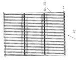
도 1은 형성된 기재 시트의 등각 투영도(isometric view)이다.
도 2는 몰드의 저부 캐비티 상의 도 1에서와 같은 기재 시트의 등각 투영도이다.
도 3은 기재 시트 상의 몰드 삽입체를 지닌 도 2에서와 같은 몰드의 저부 캐비티 상의 기재 시트의 등각 투영도이다.
도 4은 몰드의 상부 캐비티를 지닌 도 3에서와 같은 기재 시트 상의 몰드 삽입체를 지닌 몰드의 저부 캐비티 상의 기재 시트의 등각 투영도이다.
도 5는 도 1에서와 같은 두 개의 형성된 기재 시트로 제조된 기재의 단면도이다.
도 6은 도 5의 기재의 등각 투영도이다.
도 7은 도 5에서와 같은 기재 상의 반투과성 코팅을 지닌 멤브레인의 단면도이다.
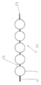
도 8은 번들로 조립되는 도 7에서와 같은 다수의 멤브레인의 분해된 등각 투영도이다.
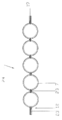
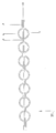
도 9는 멤브레인 번들의 단면도이다.
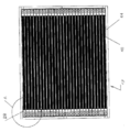
도 10은 한 단부에서 투과물 헤더로 포팅(potting)되는 멤브레인 번들의 단면도이다.
도 11은 양 단부에서 투과물 헤더로 포팅되는 멤브레인 번들을 지닌 멤브레인 모듈의 평면도이다.
도 12는 도 11의 다수의 모듈을 지닌 카세트의 평면도이다.
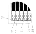
도 13은 도 12의 카세트의 코너의 확대도이다.
도 14는 도 12의 카세트의 측면도이다.
도 15는 두 개의 기재 시트 사이에 중간 플랫 시트를 지닌 투과물 시트의 측면도이다.
도 16은 파동 형상(undulating profile)을 갖는 기재로 제조된 투과물 시트의 측면도이다. Figure 1 is an isometric view of a formed substrate sheet.
Figure 2 is an isometric view of the substrate sheet as in Figure 1 on the bottom cavity of the mold.
Figure 3 is an isometric view of a substrate sheet on the bottom cavity of the mold as in Figure 2 with a mold insert on the substrate sheet.
4 is an isometric view of the substrate sheet on the bottom cavity of the mold with the mold insert on the substrate sheet as in Fig. 3 with the upper cavity of the mold. Fig.
5 is a cross-sectional view of a substrate made of two formed substrate sheets as in FIG.
Figure 6 is an isometric view of the description of Figure 5;
Figure 7 is a cross-sectional view of a membrane with a semipermeable coating on the same substrate as in Figure 5;
Figure 8 is an exploded isometric view of a number of membranes as in Figure 7 assembled into a bundle.
9 is a cross-sectional view of the membrane bundle.
10 is a cross-sectional view of a membrane bundle being potted with a permeate header at one end.
11 is a plan view of a membrane module with membrane bundles ported to a permeate header at both ends.
Figure 12 is a top view of a cassette having a plurality of modules of Figure 11;
13 is an enlarged view of a corner of the cassette of Fig.
14 is a side view of the cassette of Fig.
15 is a side view of a permeant sheet having an intermediate flat sheet between two base sheets;
16 is a side view of a permeable sheet made of a substrate having an undulating profile.
본 명세서에서, "시트" 또는 "기재 시트"는 전형적으로 다수의 함몰부를 갖도록 성형될 수 있는 기재 물질의 조각을 나타낸다. "투과물 시트" 또는 "기재"는 전형적으로 함께 접합되어 있는 두 개의 시트를 나타낸다. "투과물 채널"은 전형적으로 시트의 내측 표면에 의해 형성된 기재의 내측 상의 채널로서, 이를 통해 액체가 기재의 면에 대해 평행하게 기재의 에지로 흐를 수 있는 채널을 나타낸다. "커넥터(connector)"는 두 개의 인접하는 함몰부 사이에 있는 시트의 일부이거나, 두 개의 인접하는 투과물 채널 사이에 있는 투과물 시트의 일부를 나타낼 수 있다. "삽입체(insert)"는 몰드의 상부 다이와 저부 다이 사이에 배치되며, 함몰부 또는 투과물 채널의 내측 표면의 일부 또는 전부를 성형하는데 사용되는 몰드의 일부를 나타낼 수 있다. "멤브레인 시트"는 그 위에 코팅된 분리층을 지닌 투과물 시트를 나타낼 수 있다. As used herein, "sheet" or "substrate sheet" typically refers to a piece of substrate material that can be shaped to have a plurality of depressions. "Permeate sheet" or "substrate" typically refers to two sheets bonded together. A "permeate channel" is typically a channel on the inside of a substrate formed by the inner surface of the sheet, through which the liquid can flow to the edge of the substrate parallel to the plane of the substrate. A "connector" may be a portion of a sheet between two adjacent depressions, or a portion of a permeant sheet between two adjacent permeate channels. An "insert" is placed between the upper die and the lower die of the mold and may represent a portion of the mold used to mold some or all of the inner surface of the depression or permeate channel. A "membrane sheet" may refer to a permeate sheet having a separation layer coated thereon.
하기에서 보다 상세히 기술될 시트, 및 이를 제조하는 방법의 예에서, 시트는 열 처리되는 부직포 물질의 조각으로부터 제조되고, 캐비티 내로 압착되어 다수의 함몰부, 다르게는 리플(ripple)을 지닌 형상을 형성한다. 본원에서 기술되는 예에서, 함몰부는 커넥터에 의해 분리된다. 커넥터는 접촉하거나 공통의 면 내에 놓여진다. 본원에서 기술되는 예에서, 커넥터는 본질적으로 플랫형이고, 함몰부는 본질적으로 반원통형이다. 두 개의 이들 시트가 함몰부에 평행한 이들 두 개의 외측 에지, 다르게는 소위 플랜지에서, 그리고 이들의 커넥터 중 하나 이상, 바람직하게는 전부에서 함께 부착된다. 이는 평행한 일반적으로 원통형인 투과물 채널의 어레이를 지닌 투과물 시트를 형성하며, 각 채널은 각각의 시트로부터 리플인, 두 개의 반원통형 리플에 의해 형성된다. 투과물 시트는 채널에 수직인 두 개의 개방된 에지를 지니며, 이때 투과물 채널은 방출한다. 투과물 시트는 필요한 경우 최종 크기 및 형상으로 트리밍(trimming)될 수 있다. 시트가 멤브레인 물질로 사전 코팅되지 않은 경우, 투과물 시트는 코터(coater)에 공급되어, 멤브레인 도프가 투과물 시트의 외측 표면 상에 캐스팅된다. 이후, 코팅된 투과물 시트는 켄칭조 또는 응결조로 전달되어, 거기에서 도프가 분리층을 지닌 고체 멤브레인 물질로 변형된다. 멤브레인 물질은 상 분리 공정, 예를 들어 TIPS 또는 NIPS 공정에 의해 형성될 수 있다. 형성되는 멤브레인 시트는 켄칭조로부터 제거되고, 추가로 헹구어지고, (필요에 따라) 함침되고, 건조된다. 다수, 예를 들어, 2 내지 50개의 멤브레인 시트가 타깃 시트간 공간(target inter-sheet spacing)에 따라 이들의 개방 단부에서 함께 부착되어 번들을 형성할 수 있다. 번들의 하나 이상의 개방 단부가 영구적으로 또는 제거가능한 시일(seal)로 투과물 헤더에 부착되어 모듈을 형성한다. 모듈은 예를 들어 압력 파괴 시험에 의해 무결점 시험될 수 있다. 모듈은 여과 탱크로의 삽입에 적합한 카세트를 제조하기 위해 구조적 요소를 포함하는 카세트로 조립된다. 멤브레인 시트는 탱크내에서 일반적으로 수직으로 배향되고, 채널은 대채로 수평으로 배향되며, 헤더는 카세트의 측면에 위치하고, 일반적으로 수직으로 배향된다. 또한, 카세트는 바람직하게는 멤브레인 시트 간의 공간으로 버블을 방출시키도록 구성된 보다 하부의 폭기 격자(lower aeration grid)를 갖는다. 하기에서 보다 상세히 논의될 도면은 시트, 시트를 제조하기 위한 몰드, 모듈, 및 카세트의 예를 제시한다. In the example of a sheet to be described in more detail below, and a method of making it, the sheet is made from a piece of heat treated nonwoven material and pressed into a cavity to form a shape with a plurality of depressions, alternatively ripples do. In the example described herein, the depression is separated by a connector. The connectors may be in contact or in a common plane. In the examples described herein, the connector is essentially flat and the depressions are essentially semi-cylindrical. Two of these sheets are attached together at these two outer edges parallel to the depression, in other so-called flanges, and in one or more, preferably all, of their connectors. Which forms a permeate sheet with an array of parallel, generally cylindrical permeate channels, each channel being formed by two semicylindrical ripples that are ripples from each sheet. The permeate sheet has two open edges perpendicular to the channel, where the permeate channel emits. The permeate sheet can be trimmed to its final size and shape, if desired. If the sheet is not pre-coated with the membrane material, the permeate sheet is fed to the coater, and the membrane dope is cast on the outer surface of the permeate sheet. The coated permeate sheet is then transferred to a quenching or condensation bath where the dope is transformed into a solid membrane material with a separation layer. The membrane material may be formed by a phase separation process, for example a TIPS or NIPS process. The formed membrane sheet is removed from the quenching bath, further rinsed, impregnated (if necessary) and dried. A number of, for example, 2 to 50 membrane sheets may be attached together at their open ends along the target inter-sheet spacing to form a bundle. One or more open ends of the bundle are permanently attached to the permeate header with a removable seal to form a module. The module may be tested for integrity, for example, by pressure fracture tests. The module is assembled with a cassette containing structural elements to produce a cassette suitable for insertion into a filtration tank. The membrane sheet is oriented generally vertically in the tank, the channels are horizontally oriented, and the headers are located on the sides of the cassette and are generally vertically oriented. The cassette also preferably has a lower aeration grid configured to discharge bubbles into the space between the membrane sheets. The figures discussed in more detail below provide examples of sheets, modules, and cassettes for making sheets.
도 1과 관련하면, 시트(7)는 부직포의 조각으로 제조된다. 일련한 평행한 반원통형 함몰부(6)를 지닌 형상으로 압착된 시트(7)는 소정 간격으로 이격되며, 플랫 커넥터(5)에 의해 분리된다. 외측 함몰부는 두 개의 에지 플랜지(4)에 의해 경계를 갖는다. 반원통형 함몰부(6)의 반경은 예를 들어, 적용에 의거하여 0.3 mm 내지 5 mm이다. 1, the
도 2 내지 4와 관련하면, 저부 캐비티(9), 상부 캐비티(11), 및 다수의 삽입체(8)(하나만 도시됨)를 포함하는 몰드(10)이 성형 공정에 사용된다. 저부 캐비티(9)는 최종 몰딩된 시트(8)의 외측 형상과 일치한다. 삽입체(8)는 금속성일 수 있으며, 캐비티(9, 11)와 함께 사용되어 반원통형 함몰부(6)를 형성한다. 삽입체8)는 몰드(10)의 별개의 구성요소일 수 있거나, 몰드(10)의 상부 캐비티(11)에 내장될 수 있다. 몰드가 내장된 삽입체(8)를 갖는 경우, 삽입체는 고정되거나 자유롭게 회전할 수 있는 능력을 가질 수 있다. 회전하거나 탈착되는 삽입체(8)는 몰드 폐쇄 단계 동안 부직포 기재 물질의 슬라이딩을 허용한다. 고도로 폴리싱된 (미러 피니시(mirror finish)) 물질이 몰드의 두 캐비티(9, 11) 및 삽입체(8)에 사용된다. 초기에 플랫형인 부직포 기재의 한 조각이 몰드의 저부 캐비티(9)에 로딩(loading)된다(도 2). 이 조각은 초기에 사전-설정된 치수로 커팅된다. 기재 조각의 로딩 후, 삽입체(8)가 기재 조각 상에 놓이고(삽입체가 상부 캐비티(11)로 내장되지 않을 경우), 상부 캐비(11)은 삽입체(8) 위에 놓인다. 이후, 몰드(10)는 폐쇄되고, 캐비티(9, 11) 간에 압력이, 예를 들어 이들 캐비티를 함께 클램핑(clamping)함으로써 가해진다. 이로써, 상부 캐비티(11) 및 삽입체(8)는 시트(7)를 저부 캐비티(9)내로 압착시킨다. 2 to 4, a mold 10 including a bottom cavity 9, an upper cavity 11, and a plurality of inserts 8 (only one shown) is used in the molding process. The bottom cavity (9) coincides with the outer shape of the final molded sheet (8). The insert 8 may be metallic and used with the cavities 9, 11 to form a semi-cylindrical depression 6. The insert 8 can be a separate component of the mold 10 or can be embedded in the upper cavity 11 of the mold 10. If the mold has an embedded insert 8, the insert may have the ability to be fixed or free to rotate. The insert 8, which is rotated or detached, allows sliding of the nonwoven base material during the mold closing step. A highly polished (mirror finish) material is used for the two cavities 9, 11 and the insert 8 of the mold. A piece of the nonwoven fabric substrate which is initially flat is loaded into the bottom cavity 9 of the mold (Fig. 2). This piece is initially cut to a pre-set dimension. After the loading of the substrate piece, the upper cavity 11 is placed on the insert 8, when the insert 8 is placed on the substrate piece (if the insert is not embedded in the upper cavity 11). The mold 10 is then closed and the pressure between the cavities 9, 11 is applied, for example, by clamping these cavities together. Thereby, the upper cavity 11 and the insert 8 press the
프로토타입(prototype) 몰드(10)의 상부 캐비티(11)는 저부 캐비티(9)와 동일한 내부 형상을 지닌다. 도 2 내지 4에 도시된 몰드(10)는 몰드(10)를 폐쇄하기 전에 삽입체(8)과 상부 캐비티(11) 사이에 기재의 또 다른 조각을 삽입시킴으로써 두 개의 시트를 동시에 몰딩할 수 있다. 각각의 몰드 캐비티는 바람직하게는 최종 시트(7)의 두께 및 형상에 대해 우수한 제어를 제공하는 엄격한 허용오차(tight tolerance) 내에서 잘 기계처리된다. 특히, 시트(7)의 어떠한 부분의 과다짐(over compaction)은 바람직하지 않다. 몰딩 공정 동안에 열이 가해진다. 열 단계 후, 몰드는 시트(또는 시트들)이 그 형상을 유지할 수 있을 때까지 폐쇄된 상태로 냉각된다. 이러한 방식으로, 시트(7)는 캐비티(9)의 내측 표면에 대해 압착되면서 초기에 가열된 후 냉각된다. 시트(7)는 캐비티(9)의 내측 표면에 대해 압착되면서 바람직하게는 그것의 열변형 온도(heat deflection temperature)(HDT) 또는 그 초과로 가열된다. 또한, 시트(7)는 캐비티(9)의 내측 표면에 대해 압착되면서, 바람직하게는 그것의 HDT 미만으로, 더욱 바람직하게는 그것의 유리 전이 온도(Tg) 미만으로 냉각된다. 이로써 시트(7)는 캐비티 내측 표면에 상응하는 외측 표면을 갖는 영구적인 형상을 얻는다. The upper cavity 11 of the prototype mold 10 has the same internal shape as the lower cavity 9. [ The mold 10 shown in Figures 2 to 4 can mold two sheets simultaneously by inserting another piece of substrate between the insert 8 and the upper cavity 11 before closing the mold 10. [ . Each mold cavity is preferably well machined within a tight tolerance that provides good control over the thickness and shape of the
플랫 시트 UF 멤브레인용 기재로서 일반적으로 사용되는 부직포, 예를 들어, 폴리에스테르계 패브릭이 기재 물질로 사용될 수 있다. 히로스(Hirose)(05TH-80W)로부터의 샘플, 3M 포웰(Powell)로부터의 세 가지 등급, 및 크란 논위븐스(Crane Nonwovens), 아와 페이퍼(AWA Paper), 및 알스트롬(Ahlstrom)로부터의 다수의 등급을 포함하는 상이한 공급업자로부터의 샘플이 프로토타입 몰드를 사용하여 시험되었다. 기재 물질은 두께 범위가 80 내지 120 마이크론이고, 공기 투과율이 5 내지 15cc/cm2/sec이다. 기재 물질은 몰딩 전에 건조된다. 기재 물질은 일반적으로 열적으로 결합된 짧은 섬유와 보다 긴 보강 섬유의 매트릭스를 갖는다. 시험 샘플 모두 허용가능한 시트(7)를 생성하였다. Nonwovens commonly used as substrates for flat sheet UF membranes, such as polyester based fabrics, can be used as the base material. Samples from Hirose (05TH-80W), three grades from 3M Powell, and a number of grades from Crane Nonwovens, AWA Paper, and Ahlstrom ≪ / RTI > were tested using prototype molds. Base materials are the thickness range 80 to 120 microns, and the air permeability of 5 to 15cc / cm 2 / sec. The base material is dried before molding. The base material generally has a matrix of thermally bonded short fibers and longer reinforcing fibers. All of the test samples produced an acceptable sheet (7).
기재의 조성에 의거하여, 몰딩 온도는 100F (38℃) 이상이고, 시험에서 300 내지 500 F (149 내지 260℃)에서 달라진다. 비교시, 폴리에스테르의 Tg는 약 60 내지 75℃이고, 폴리에스테르의 HDT는 약 170 내지 177℃이고, 폴리에스테르의 융점(Tm)은 약 255℃일 수 있으며, 이들 모든 온도는 폴리에스테르 형태에 의거하여 달라진다. 온도는 바람직하게는 매트릭스 섬유 및 보강 섬유의 HDT를 초과하며, 임의로, 또한 매트릭스 섬유의 융점을 초과하지만, 바람직하게는 보강 섬유의 융점보다는 낮다. 몰드는 기재가 캐비티(9, 11)의 내측 표면에 상응하는 형상을 취하도록 충분히 오래 동안, 그러나 멤브레인 도프가 여전히 기재에 침투하여 고정될 수 있도록 기재 공기 투과율을 상당 부분 유지하는 시간과 온도의 조합으로 가열된다. 열은 몰드(10)를 온도 조절 오븐에 배치함으로써 제공된다. 사이클 시간은 가열 동안 5 내지 10분 사이에서, 그리고 냉각에 대해 30분 초과에서 달라진다. 제조를 위해, 내장 수(또는 그 밖의 냉각제) 라인(사출 성형과 유사함)을 지닌 몰드는 냉각 공정을 상당히 단축시킬 것으로 예상될 수 있다. 몰드 구성요소(9, 8, 11)는 요망하는 최종 시트(7) 두께, 예를 들어, 0.05 내지 0.1 mm를 생성하도록 사이징된다. 형성된 시트(7)는 제 1 프로토타입 몰드로 제조되는 경우, 두께가 0.075 mm이다. 벽 두께를 감소시키고, 시트(7)의 몰딩된 형상을 유지시키는 능력을 증가시키기 위해 소정의 다짐(compaction)이 허용되며, 가능하게는 바람직하다. 몰드 폐쇄 및 유지 압력은 15 내지 20 psi의 범위이다. 매우 큰 시트(7)에 대한 몰드는 보다 높은 폐쇄 압력을 요할 수 있지만, 동일한 유지 압력을 사용할 수 있다. 두 개의 시트(7)가 제거가능한 원통형 금속 삽입체(8)를 사용하여 제 1 프로토타입 몰드로 동시에 몰딩된다. 몰딩된 시트(7)는 몰드에 사용된 삽입체(8) 및 캐비티(9, 11)에 일치하는 내측 및 외측 반경을 유지한다. 프로토타입 몰드(10)의 캐비티(9, 11)내 함몰부의 내측 표면의 반경은 약 1.5 mm이다. 제 2 프로토타입 몰드에서, 캐비티 내 함몰부의 내측 표면의 반경은 약 0.6 mm이다. 물의 정밀여과 또는 한외여과를 위한 최적의 직경은 루멘 압력 강하를 허용하면서 패킹 밀도를 최대화하기 위해 0.7 mm에 가까울 수 있다. Based on the composition of the substrate, the molding temperature is above 100F (38 DEG C) and varies from 300-500 F (149-260 DEG C) in the test. In comparison, the Tg of the polyester may be about 60-75 ° C, the HDT of the polyester may be about 170-177 ° C, and the melting point (Tm) of the polyester may be about 255 ° C, . The temperature preferably exceeds the HDT of the matrix fibers and reinforcing fibers and, optionally, also exceeds the melting point of the matrix fibers but is preferably lower than the melting point of the reinforcing fibers. The mold has a combination of time and temperature that is long enough to allow the substrate to assume a shape corresponding to the inner surface of the cavity 9,11 but still maintain a substantial portion of the substrate air permeability so that the membrane dope can still penetrate and be fixed to the substrate. . Heat is provided by placing the mold 10 in a temperature control oven. Cycle times vary between 5 and 10 minutes during heating and over 30 minutes during cooling. For manufacturing, molds with built-in water (or other coolant) lines (similar to injection molding) can be expected to significantly shorten the cooling process. The mold components 9,8, 11 are sized to produce the desired
도 5 및 6과 관련하면, 몰딩 후, 시트(7)는 최종 치수로 트리밍되고, 한쌍의 시트(7)가 투과물 시트(20)로 조립된다. 시트(7)는 접합 영역(12)에서 함께 부착된다. 상기 기술된 바와 같이 프로토타입 몰드로 제조된 시트(7)는 에폭시, 수계 접착제 및 폴리우레탄을 포함하는 여러 타입의 접착제를 사용하여 함께 접합된다. 시트(7)를 형성하는데 사용되는 동일한 몰드(10)가 두 개의 시트(7)를 함께 결합시키는데 사용된다. 접합 영역(12)의 몰드(10)로의 점착 및 기재 물질을 통한 접합제의 완전 침투로 인해 이후 멤브레인으로 코팅될 표면의 오염을 제거하기 위해, 보다 높은 점도의 접착제가 바람직하다. 함께 결합되는 경우에, 상기 기술된 바와 같이 제 1 프로토타입 몰드로 제조된 두 개의 시트(7)는 약 2mm의 외경들 사이의 간격 및 3mm 외경을 갖는 원통형 채널을 지닌 투과물 시트(20)를 생성한다. 투과물 시트(20)의 전체 치수는 약 10인치(25 cm) x 11/2 인치(37 cm)이지만, 보다 큰 시트(7)가 제조될 수도 있다. 제 2 프로토타입 몰드로 제조된 두 개의 시트(7)는 약 1mm의 외경들 사이의 간격 및 1.2mm의 외경을 갖는 원통형 채널을 지닌 투과물 시트(20)를 생성한다. 이들 시트(20)의 크기는 약 125 mm x 120 mm이다. 두 프로토타입 몰드로부터 형성된 투과물 시트(20)는 함몰부(6)와 커넥터(5) 사이에 빳빳한 전이부를 갖는 형상을 자가 지지하고 유지한다. 5 and 6, after molding, the
일반적으로, 두 개의 시트(7)는 폴리우레탄, 에폭사이드 또는 실리콘과 같은 열경화성 물질을 사용하거나, 핫 멜트(열가소성 물질), 또는 그 밖의 접착제(19)를 사용함으로써 함께 부착될 수 있다. 접착 공정은 시트(7)를 형성하는데 사용된 몰드(10)와 유사한 별개의 접착 몰드에서 일어날 수 있다. 먼저, 저부 시트가 몰드 내로 로딩된다. 접착제는, 분배기, 예를 들어 컴퓨터에 의해 제어되는 서보(servo)에 의해 이동하는 접착제 프린팅 헤드 또는 롤러를 사용하여 적용된다. 다음으로, 원통형 삽입체가 이미 몰딩된 반원형 형상 내측에 배치될 수 있다. 이들 삽입체의 외경은 새로 형성된 채널의 의도된 내경에 일치할 것이다. 삽입체가 임의적으로 사용되지만, 삽입체는 투과물 채널의 우수한 진원도(roundness)를 보장하도록 돕는다. 그러나, 또한 조립 공정은 삽입체(8)를 사용하지 않고 프로토타입 형성 몰드(10)로 수행된다. 이러한 경우, 삽입체의 로딩 및 제거와 관련된 공정 단계가 확실하게 제거된다. 저부 시트(7)는 몰드의 저부 캐비티에 로딩되고, 상부 시트(7)는 몰드(10)의 상부 캐비티에 로딩된다. 몰드를 폐쇄한 후, 두 개의 시트는 서로 단지 접합 영역에서만 접촉할 것이다. 몰드가 폐쇄된 채로, 사용되는 접착제에 대해 요구될 경우에 압력 및 열이 새로 생성된 구조물에 가해질 수 있다. 접촉 표면은 함께 접착되어 투과물 시트(20)를 형성할 것이다. 사이클이 완료되면, 몰드는 개방되고, 삽입체가 제거된다. 투과물 시트(20)는 접착 몰드로부터 제거될 것이고, 필요에 따라 최종 치수로 트리밍되고, 주형기(casting machine)로 옮겨질 것이다. 시트(7)는 예를 들어, 폴리에틸렌 테레프탈레이트(PET)의 낮은 표면 에너지 섬유를 포함할 수 있는데, 이는 강력한 접합을 달성하기 어렵게 할 수 있다. 특히 강력한 접합은 메틸 메타크릴레이트 접착제 시스템(MMA), 에폭시 및 폴리우레탄(PUR) 핫 멜트 접착제를 사용함으로써 PET계 시트(7)에서도 제공된다. In general, the two
접합을 위한 또 다른 선택사항은 열가소성 (핫 멜트) 와이어(wire)를 사용하는 것이다. 와이어가 접합 영역(12) 가운데 저부 시트의 상부에 배치된다. 몰드의 다른 측에 로딩된 다른 시트(7)는 제 1 시트의 상부에 배치될 것이다. 압력 및 온도는 와이어가 두 시트(7)를 용융시키고, 피상적으로 침투하여, 이들을 함께 결합시킬 때까지 가해진다. 앞서 기술된 바와 같이, 상기 공정은 삽입체를 사용하거나 사용하지 않고 이루어질 수 있다. Another option for bonding is to use thermoplastic (hot melt) wire. A wire is disposed at the top of the bottom sheet in the middle of the
사용될 수 있는 제 3의 조립 방법은, 음파, 마찰 또는 레이저 융착이다. 커넥터에 따른 접합의 지속성은, 어느 한 채널에서 다른 채널로 흐르는 투과물이 오염화를 생성하지 않기 때문에, 공정에 대해 가장 중요한 것은 아니다. 접합 영역(12) 뒤에 블랙 PTFE 배킹 플레이트(black PTFE backing plate)로, 또는 시트(7) 사이에 젠텍스 코포레이션(Gentex Corporation)에 의해 판매되는 Clearweld™ 시스템과 같은 근적외선 흡수 융착 물질로 레이저 융착시키는 것이 특히 강력한 접합을 제공한다. A third method of assembly that can be used is sonic, friction or laser welding. The continuity of the connection along the connector is not critical to the process, since the permeate flowing from one channel to the other does not produce contamination. Such as the Clearweld (TM) system sold by Gentex Corporation, as a black PTFE backing plate behind the bonded
투과물 시트(20)의 증가된 투과물 시트 활성 표면 및 구조적 강도를 위해, 다른 조립 방법이 사용될 수 있다. 얇은 다공성 물질이 조립 공정 전에 두 시트 사이에 배치될 수 있다. 이러한 투과물 운반 매체는 커넥터(6) 영역에서 멤브레인을 통해 투과되는 액체가 접합 영역(12)에서 두 시트(7) 사이를 흘러 투과물 채널로, 그리고 투과물 헤더로 나아가게 할 것이다. 융착 또는 접착제는 두 시트를 함께 (다공성 물질을 통해) 고정시키고, 역세척 동안 투과물 시트(20)에 구조적 강도를 제공할 수 있다. 그러나, 이러한 다공성 물질은 단지 선택사항이다. 투과물을 어느 한 투과물 채널과 다른 투과물 채널 사이를 흐르게 하는 것은 필수적이지 않으며, 일부 투과물은 심지어 다공성 물질의 없는 경우에서 커넥터 영역으로부터 투과물 채널로 흐를 수 있다. 임의로, 특히 멤브레인 시트가 역세척되지 않을 경우, 그러나, 가능하게는 역세척될 경우라도, 시트(7) 간에 또는 시트(7)과 중간 물질 간의 융착 또는 접착제 부착은 커넥터(5)의 영역이 보다 많은 투과물을 통과시키도록 예를 들어, 커넥터(5)를 따라 일련의 접착제 도트(dot)의 형태로, 불연속적일 수 있다. For increased permeate sheet active surface and structural strength of the
추가적 강도를 위해, 투과물 시트(20)는 임의로 에지 상에, 또는 커넥터 영역(5) 중 하나 이상에, 또는 이 둘 모두 상의 두 시트(7) 사이에 개재된 강성 삽입체를 지닐 수 있다. 앞서 기술된 조립 공정 동안에 보강물이 첨가된다. 강성 삽입체는 매우 얇은, 높은 인장 강도 물질, 바람직하게는 보강물이 있거나 없는 플라스틱 물질로 제조된다. 이드 삽입체는 투과물 시트가 수평 상태의 투과물 채널로 설치되는 경우, 실제 작업 동안 중량 증가에 의해 생성되는 응력을 보상할 것이다. 모듈 내 시트의 배향은 적용 타입, 수압 계산, 및 오염 보호 및 세정 프로토콜에 사용되는 공정 타입에 의해 결정될 것이다. 추가의 보강물이 투과물 시트(20)의 중앙에, 또는 투과물 시트(20) 전체에 걸쳐 다른 위치에 배치될 수 있다. For additional strength, the
도 15에 도시된 바와 같이, 또 다른 선택사항은 두 시트(7)의 전체 영역 사이에 시트형 삽입체(50)에 의해 삽입체 또는 중간 물질을 제공하는 것이며, 이에 따라 모든 원통형 투과물 채널에 대해 두 개의 반원통형 투과물 채널을 생성하는데, 이는 삽입체(50) 없이도 형성될 수 있다. 이러한 삽입체(50)는 상기 기술된 바와 같은 시트(7)를 보강하도록 강성일 수 있거나, 상기 기술된 바와 같이 시트(7)의 커넥터(5) 영역의 활성을 증가시키도록 투과성일 수 있다. 또한, 삽입체(50)는 강성이거나, 강성이 아니거나 간에, 그리고 다공성이거나 다공성이 아니거나 간에 시트(7)를 함께 부착시킬 수 있게 하는데 사용될 수 있다. 접착제 또는 융착 증진 물질이 삽입체(50)의 양 측면에 적용될 수 있는데, 예를 들어 박층으로 분무되거나 라인 또는 도트 격자로서 프린팅될 수 있다. 이에 따라 두 시트(7) 사이에 삽입체(50)를 배치하는 것은 접착제 또는 융착 증진 물질을 커넥터(5)에 적용하는 대안의 방법을 제공한다. 접착제가 사전-적용되거나 사전-적용되지 않거나 간에, 삽입체(50)는 또한 함몰부(6)과 커넥터(5) 간에 빳빳한 차별부가 존재하지 않는 경우, 예를 들어, 시트(7)가 도 16에 도시된 바와 같은 파동 형상을 갖는 경우, 시트(7) 간의 확실한 접합을 제공하도록 도울 수 있다. 삽입체(50)는 예를 들어, 고형막, 예를 들어, 마일라(mylar)의 고형막이거나, 폴리아미드(PA, 나일론) 섬유의 3차원 매트릭스와 같은 부직포 시트일 수 있다. As shown in Figure 15, another option is to provide an insert or intermediate by sheet-
투과물 시트(20)가 형성된 후, 폴리머성 멤브레인 도프가 양면 상에 캐스팅된다. 이는 양면에 대해 동시에 또는 순차적으로 (한번에 한면) 이루어질 수 있다. 투과물 시트(20)는 도프를 적용하는 주형기를 통해 제공된다. 주형기는 투과물 시트(20)의 외측 형상에 상응하는 형상을 지닌 중공의 섬유 코팅기의 방적돌기(spinneret)와 유사한 다이(die)를 갖는다. 도프는 투과물 시트(20)가 존재하는 경우 가스압 또는 정량 기어 펌프(metering gear pump)를 사용하여 주형기에 제공된다. 적용되는 도프층의 속도 및 두께는 제어된다. 또한, 주형기 내측의 내부 압력, 온도, 및 도프 점성과 같은 그 밖의 공정 파라미터가 제어된다. 주형기는 투과물 시트(20)의 외측 형상과 일치하는 형상을 갖는다. 투과물 시트(20)는 수직 또는 수평으로 주형기에 공급되나, 수직 공급이 도프가 접합 영역(12) 쪽으로 흐르는 경향을 감소시킨다. 주형기의 출구는 도프가 투과물 시트(20) 상으로 일반적으로 일정한 두께로 분산되도록 하는 갭(gap)을 유도한다. 이후, 코팅된 투과물 시트(20)는 응결조 및 헹굼조를 통과한다. 이러한 공정은 멤브레인 시트(24)를 생성하기 위해 도 7에 도시된 바와 같이 상 반전(phase inversion) 멤브레인 형성에 의해 투과물 시트(20)의 상부 상에 고형 멤브레인 층(23)을 형성할 것이다. 이후, 멤브레인 시트(24)는 헹구어지고, 함침되고(UF 만으로), 오프라인 공정으로 건조된다. 제 1 프로토타입 몰드로 제조된 시트(20)는 약 140 마이크론 두께의 층으로 폴리설폰에 의해 코팅된다. 폴리설폰은 투과물 시트(20)를 함침시키지만, 멤브레인 시트(24)의 내측 투과물 채널을 채운다. After the
대안으로, 멤브레인 시트(24)는 또한 시트(7)를 제조하기 전에 기재 시트 상에 멤브레인을 형성시킴으로써 제조될 수 있다. 플랫 시트 멤브레인은 일반적인 주형기로 캐스팅될 수 있다. 이후, 플랫 시트 멤브레인은 몰드(10)에서 몰딩된 멤브레인 시트로 형성되고, 또 다른 이러한 시트와 함께 멤브레인 시트(24)로 조립된다. 몰딩 공정은 상이한 사이클 시간을 가질 것이고, 상이한 공정 파라미터를 사용할 것이다. Alternatively, the
도 8, 9 및 10과 관련하면, 수개의 멤브레인 시트(24)가 결합하여 번들(26)을 형성할 수 있다. 어떠한 수의 멤브레인 시트(24)가 사용될 수 있지만, 바람직한 범위는 플라스틱 헤더 몰딩에 대한 요망하는 시트간 간격 갭 및 한계치에 기초하여 15 내지 50이다. 번들(26)은 채널 단부를 커팅하여 개방하면서, 순간 정적 포팅(fugitive static potting) 또는 원심분리 포팅(centrifuge potting)과 같은 통상적인 방법에 따라 폴리우레탄과 같은 수지를 사용하여 플라스틱 헤더 몰딩(28) 내에 포팅(potting)될 수 있다. 도 8, 9 및 10에 도시된 바와 같은, 대안의 포팅 방법은 플라스틱 삽입체(31, 32)를 사용하여 멤브레인 시트(24)를 함께 차후 헤더 몰딩(28) 내 시이트(seat)로 삽입될 수 있는 포팅 블록 또는 브릭(25)에 부착시키는 것이다. 임의로, 다수의 멤브레인 시트(24)가 두 삽입체(31, 32) 사이에 연달아 놓일 수 있다. 예를 들어, 길이가 약 1m인 삽입체(31, 32)는 각각의 높이가 약 25mm인 4개의 멤브레인 시트(24)를 지지할 수 있다. 또한, 임의로, 다공성 디바이더(34)가 시이트의 저부를 형성할 수 있다. 블록(25)은 수지(36)를 블록(25) 위 헤더 시이트로 부음으로써 맞게 포팅된다. 투과물은 채널을 통해 흐르고, 채널의 개방 단부를 통해 블록(25)에서 배출되고, 경우에 따라 디바이더(34)를 통해 흘러 헤더(28) 내 투과물 리셉터클(27)로 유입된다. 투과물은 투과물 스피것(spigot)(25)을 통해 투과물 리셉터클(37)로부터 제거될 수 있다. 8, 9, and 10,
도 11은 모듈(40)을 도시한 것이다. 두 투과물 헤더(40) 사이의 블랙 영역은 도 10에 보다 상세히 도시된 바와 같이 갭(27)에 의해 이격되어 있는 멤브레인 시트(24)의 번들(26)을 나타낸다. 멤브레인 시트는 예를 들어, 0.5cm 내지 5cm의 중심에서 중심 거리로 분리될 수 있다. 임의로, 멤브레인 시트(24)는 어느 하나의 리플이 또 다른 것의 커넥터로부터 횡으로 배치되면서, 서로에 대해 엇갈리게 배치될 수 있다. 도 12는 프레임(44) 내에 함유된 수개의 모듈(40)을 지닌 카세트(42)의 평면도를 도시한 것이다. 투과물 헤더(미도시됨)는 모듈(40)의 투과물 스피것(35)에 연결된다. 프레임(44), 헤더(28) 및 존재하는 경우, 임의의 투과물 파이프가 카세트(42)의 측면에 배치되어 유체가 갭(27)을 통해 위쪽으로 이동할 수 있게 한다. 모듈(40)은 상부 또는 저부 모듈(40)의 투과물 리셉터클(37)로 플러깅되는 어느 한 모듈(40)의 투과물 스피것(25)으로 스택킹(stacking)될 수 있다. 도 14에서, 예를 들어, 세 개의 모듈(40)이 함께 수직 컬럼으로 스택킹된다. 도 13과 관련하면, 카세트(42)의 프레임(44)은 카세트(42) 내에 모듈(40)을 제 위치에 놓이게 돕도록 헤더(28)의 정렬 그루브(30)에 대해 형상 및 크기가 상응하는 슬라이더(31)를 지지한다. Fig. 11 shows the
또 다른 선택사항은 몰딩된 플라스틱 헤더를 사용하지 않고, 최종 요소로서 블록을 사용하는 것인데, 가능하게는 헤더의 투과물 캐비티 또는 카세트로의 직접적인 삽입을 위해 플라스틱 가이드가 그것의 외주에 부착된다. 블록과 투과물 캐비티 사이에 제거가능한 시일은 블록을 투과물 캐비티로 압축함으로써, 또는 O-링과 같은 밀봉 수단에 의해 제조된다. 이러한 방법의 이점은 우레탄에 의해 블로킹되는 보다 덜 활성인 섬유, 포팅으로부터의 보다 낮은 제조 스크랩(manufacturing scrap), 증가된 카세트 패킹 밀도, 감소된 원료 비용(헤더 플라스틱 및 우레탄), 투과물 캐비티로부터 그것들을 방출시킨 후 개방된 채널 단부 피닝(pining)에 의한 현장내 용이한 채널 보수, 및 감소된 모듈 대체 비용을 포함한다. Another option is to use the block as a final element, without using a molded plastic header, possibly with a plastic guide attached to its periphery for direct insertion into the permeate cavity or cassette of the header. A removable seal between the block and the permeate cavity is produced by compressing the block into the permeate cavity, or by a sealing means such as an O-ring. Advantages of this method include less active fibers that are blocked by urethane, lower manufacturing scrap from potting, increased cassette packing density, reduced raw material costs (header plastics and urethanes) On-site easy channel repair by open channel end pining after discharge, and reduced module replacement costs.
무-헤더 설계 하에서, 섬유 번들 블록은 이중 o-링을 지닌 헤더 및 투과물 수거 채널 둘 모두로서 작용하는 몰딩된 플라스틱 말단을 지닌 스틸 프레임으로 구성된 카세트에 직접 삽입될 것이다. 1 미터 높이의 요소는 어떠한 크기의 탱크를 가득 채우기 위해 어떠한 수로 스택킹될 수 있다. 번들은 최소 응력이 존재하고, 채널이 헤더로의 용이한 맞춤을 허용하고, 번들이 함께 보다 가깝게 이격되게 하는 비투과성인 말단에서 열가소성 물질의 점증적으로 얇아지는 층을 지님으로써 테이퍼링될 것이다. 열가소성 물질은 안전을 위해 모든 모듈에 걸쳐 제지 막대(restrainer bar)가 배치되도록 상부 가까이에서 보다 두꺼울 것이다. 시스템은 감축의 경우에 조절가능할 것이다. Under a no-header design, the fiber bundle block will be inserted directly into a cassette consisting of a steel frame with a molded plastic end acting as both a header with dual o-rings and a permeate collection channel. A one meter high element can be stacked in any number to fill a tank of any size. The bundle will be tapered by having a minimally stressed and having an increasingly thinned layer of thermoplastic material at the impermeable end which allows the channel to fit easily into the header and allow the bundles to be closer together. The thermoplastic will be thicker near the top so that the restrainer bar is placed over all modules for safety reasons. The system will be adjustable in case of a reduction.
투과물 시트(20) 내측에 몰딩된 투과물 채널을 제공함으로써, 여과 탱크 내측에 활성 표면의 분포가 정확하게 제어될 수 있다. 또한, 정확하게 몰딩된 투과물 채널은 멤브레인 벽 두께를 0.3mm 또는 그 미만, 또는 0.15 mm 또는 그 미만이 되게 하고, 이는 보강된 중공 섬유 멤브레인에 대해서보다 낮은 것이다. 투과물 채널의 외경은 1 mm 또는 그 미만, 또는 0.5 mm 또는 그 미만일 수 있다. 계산된 예에서, 채널은 0.7 mm의 외경을 지니며, 멤브레인 벽 두께는 0.15 mm이다. 투과물 채널은 내경이 0.4 mm일 것이고, 이는 폭이 1m인 멤브레인 시트의 투과물 채널을 통한 투과물 흐름에 대한 상당한 압력 강하 없이 큰 용적의 투과물 흐름에 대해 충분할 것이다. By providing a permeate channel molded inside the
투과물 시트는 전형적인 플랫 시트 멤브레인에 대해 상당히 증가된 표면적을 지니며, 전형적인 플랫 시트 모듈에서 필수적인 프레임 구성요소 및 스페이서를 피하고, 멤브레인 시트(24)의 강성은 시트당 보다 큰 면적(시트의 멤브레인 표면적보다는 시트의 외부 치수와 관련하여)을 허용한다. 멤브레인 시트(24)는 폭기되는 경우에 파동치거나 진동할 수 있지만, 중공 섬유 시스템에서와 같이 인접하는 멤브레인 간에는 마찰이 거의 또는 전혀 없다. 모든 투과물 채널은 시트 내에 정확하게 배치되고, 시트들은 서로에 대해 정확하게 배치될 수 있어서 50% 까지의 패킹 밀도를 가능하게 한다. 탱크 및 모듈 패킹 밀도는 중공 섬유 시스템과 적어도 대등하다. The permeate sheet has a significantly increased surface area for typical flat sheet membranes and avoids the requisite frame elements and spacers in typical flat sheet modules and the stiffness of the
시트의 측면에 헤더를 지닌, 수직으로 배향된 시트는 상부 또는 저부 헤더 없이 시트들 간의 채널 공기에 대한 폭기 격자가 흐름을 차단하도록 한다. 공기는 각각의 시트 사이로 배향되고 위쪽으로 이동되도록 강제되기 때문에, 중공 섬유 번들내 데드 존(dead zone)에서의 오염 문제가 제거된다. 그러나, 전형적인 플랫 시트 멤브레인과는 달리, 단지 두 개의 헤더를 갖는 것이 멤브레인 시트의 약간의 진동이 멤브레인 표면에서 발생할 수 있는 슬러징(sludging)을 막는 것을 돕는다. 또한, 멤브레인 간에 잘 형성된 수직 갭이 갭을 통한 플러그-흐름을 조성하고, 이것이 평균 고형물 노출을 감소시키고, 탱크 배출 동안 고형물 배출을 위한 잘 형성된 경로를 생성한다. A vertically oriented sheet with a header on the side of the sheet allows the aeration grids to block flow of air between the sheets without the top or bottom header. The problem of contamination in the dead zone in the hollow fiber bundle is eliminated because air is forced to be directed between each sheet and moved upwards. However, unlike a typical flat sheet membrane, having only two headers helps prevent some sludging that may occur at the membrane surface from some vibration of the membrane sheet. In addition, a well-formed vertical gap between the membranes creates a plug-flow through the gap, which reduces average solids exposure and creates a well-formed path for solids discharge during tank discharge.
중공 섬유 멤브레인은 부합되는 가요성, 강도 및 캐스팅 특성으로 압출될 수 있는 폴리머로 제한되지만, 플랫 시트 캐스팅은 보다 강성의 pH 내성 폴리머, 예컨대 폴리설폰이 폴리설폰 강성으로 인한 단점을 겪지 않으면서 사용되게 한다. 또한, 투과물 시트는 침지되는 NF 필터 및 바이오반응기를 허용하는, 박막 복합물, 예컨대 NF 멤브레인 물질로 코팅될 수 있다. 예를 들어, 탄소 나노튜브(carbon nanotube), 아쿠아포린(aquaporin)을 사용하는 새로운 나노구조 멤브레인 물질, 마스킹되는 에칭(masked etching), 또는 그 밖의 신규한 공정이 또한 투과물 시트 상에서 형성되기에 적합할 수 있다. Although hollow fiber membranes are limited to polymers that can be extruded with compatible flexibility, strength, and casting properties, flat sheet casting is preferred because a more rigid pH resistant polymer, such as polysulfone, is used without suffering from the disadvantages of polysulfone stiffness do. The permeate sheet may also be coated with a thin film composite, such as an NF membrane material, which allows the NF filter and the bioreactor to be immersed. For example, new nanostructured membrane materials using carbon nanotubes, aquaporins, masked etching, or other novel processes are also suitable for being formed on the permeate sheet can do.
미국 특허 가출원 번호 제61/325,972호가 본원에 참조로 포함된다. U.S. Provisional Patent Application No. 61 / 325,972 is hereby incorporated by reference.
Claims (26)
이에 따라 하나 이상의 함몰부가 두 개의 기재 물질 시트 사이에 하나 이상의 내부 채널을 형성하고, 하나 이상의 내부 채널은 하나 이상의 외측 에지에 대해 개방되어 있는, 두 개의 기재 물질 시트를 포함하는 장치. Wherein the at least one base material sheet has at least one depression extending into the edge of the at least one base material sheet and wherein the two base material sheets have at least one depression extending into the outer edge, Are joined together along the outer edge of the sheet,
Whereby one or more depressions form one or more inner channels between two base material sheets and one or more inner channels are open to one or more outer edges.
b) 기재 물질의 조각을 가열 및 냉각하면서 기재 물질의 조각을 캐비티의 내측 표면에 대해 압착하여 기재 물질의 조각을 성형하는 단계,
c) 다이로부터 다이에 상응하는 형상을 지닌 기재 물질을 제거하는 단계를 포함하는, 멤브레인을 제조하는 방법.a) inserting a piece of substrate material into the cavity,
b) pressing a piece of substrate material against the inner surface of the cavity while heating and cooling the piece of substrate material to form a piece of substrate material;
c) removing the substrate material having a shape corresponding to the die from the die.
Applications Claiming Priority (3)
| Application Number | Priority Date | Filing Date | Title |
|---|---|---|---|
| US32597210P | 2010-04-20 | 2010-04-20 | |
| US61/325,972 | 2010-04-20 | ||
| PCT/CA2011/050201 WO2011130853A1 (en) | 2010-04-20 | 2011-04-15 | Formed sheet membrane element and filtration system |
Related Parent Applications (1)
| Application Number | Title | Priority Date | Filing Date |
|---|---|---|---|
| KR1020127030408A Division KR101892223B1 (en) | 2010-04-20 | 2011-04-15 | Formed sheet membrane element and filtration system |
Publications (2)
| Publication Number | Publication Date |
|---|---|
| KR20180100236A true KR20180100236A (en) | 2018-09-07 |
| KR101978284B1 KR101978284B1 (en) | 2019-05-14 |
Family
ID=44833599
Family Applications (2)
| Application Number | Title | Priority Date | Filing Date |
|---|---|---|---|
| KR1020127030408A KR101892223B1 (en) | 2010-04-20 | 2011-04-15 | Formed sheet membrane element and filtration system |
| KR1020187023892A KR101978284B1 (en) | 2010-04-20 | 2011-04-15 | Formed sheet membrane element and filtration system |
Family Applications Before (1)
| Application Number | Title | Priority Date | Filing Date |
|---|---|---|---|
| KR1020127030408A KR101892223B1 (en) | 2010-04-20 | 2011-04-15 | Formed sheet membrane element and filtration system |
Country Status (9)
| Country | Link |
|---|---|
| US (4) | US9492792B2 (en) |
| EP (2) | EP2560811B1 (en) |
| KR (2) | KR101892223B1 (en) |
| CN (1) | CN102892576B (en) |
| CA (2) | CA2796531C (en) |
| ES (1) | ES2940820T3 (en) |
| PT (1) | PT2560811T (en) |
| SG (1) | SG184909A1 (en) |
| WO (1) | WO2011130853A1 (en) |
Families Citing this family (19)
| Publication number | Priority date | Publication date | Assignee | Title |
|---|---|---|---|---|
| CA2796531C (en) | 2010-04-20 | 2018-11-06 | Fibracast Ltd. | Formed sheet membrane element and filtration system |
| EP2768604A4 (en) | 2011-10-20 | 2015-09-02 | Fibracast Ltd | Coating device and process for coating formed sheet membrane element |
| DK178159B1 (en) * | 2014-02-03 | 2015-07-06 | Sani Membranes Aps | Filter plate assembly |
| DE102015005100A1 (en) * | 2015-04-22 | 2016-03-03 | Mann + Hummel Gmbh | Hollow fiber arrangement, method and device for producing a hollow fiber arrangement, device with at least one hollow fiber arrangement |
| US11045768B2 (en) | 2015-09-24 | 2021-06-29 | Fibracast Ltd. | Method of operating membrane filter |
| IL265376B1 (en) | 2016-09-20 | 2024-04-01 | Aqua Membranes Llc | Permeate flow patterns |
| WO2018094287A1 (en) | 2016-11-19 | 2018-05-24 | Aqua Membranes Llc | Interfernce patterns for spiral-wound elements |
| IT201600130256A1 (en) * | 2016-12-22 | 2018-06-22 | Wamgroup Spa | DUST REMOVER FOR GASEOUS FLUIDS AND METHOD OF REALIZING IT |
| US11090612B2 (en) | 2017-04-12 | 2021-08-17 | Aqua Membranes Inc. | Graded spacers for filtration wound elements |
| JP2020517423A (en) | 2017-04-20 | 2020-06-18 | アクア メンブレインズ,インコーポレイテッド | Non-nesting, non-deformed pattern for spiral wound elements |
| US11745143B2 (en) | 2017-04-20 | 2023-09-05 | Aqua Membranes, Inc. | Mixing-promoting spacer patterns for spiral-wound elements |
| US11745144B2 (en) | 2017-10-13 | 2023-09-05 | Aqua Membranes Inc. | Bridge support and reduced feed spacers for spiral-wound elements |
| KR101927831B1 (en) * | 2017-11-15 | 2018-12-11 | 김창용 | Bendable flexible membrane module and method of manufacturing the same |
| KR102059012B1 (en) * | 2017-12-06 | 2019-12-24 | 김창용 | Water treatment apparatus using flexible membrane module |
| US11286957B2 (en) * | 2018-07-02 | 2022-03-29 | Rohr, Inc. | Method for inserting septum into acoustic liner |
| AU2019298254A1 (en) | 2018-07-03 | 2021-01-21 | Fibracast Ltd. | Tightly spaced flat sheet immersed membranes and fine bubble aeration |
| MX2022000581A (en) | 2019-07-16 | 2022-04-20 | Fibracast Ltd | System and method for feeding immersed membrane units. |
| JP2023521977A (en) | 2020-04-07 | 2023-05-26 | アクア メンブレインズ,インコーポレイテッド | Independent spacer and method |
| DE102022111482A1 (en) | 2022-05-09 | 2023-11-09 | Dr. Ing. H.C. F. Porsche Aktiengesellschaft | Battery arrangement |
Citations (2)
| Publication number | Priority date | Publication date | Assignee | Title |
|---|---|---|---|---|
| WO2001070375A1 (en) * | 2000-03-23 | 2001-09-27 | W.L. Gore & Associates Gmbh | Tubing unit |
| US7380774B2 (en) * | 2004-05-17 | 2008-06-03 | Mitsubishi Heavy Industries, Ltd. | Humidifier |
Family Cites Families (75)
| Publication number | Priority date | Publication date | Assignee | Title |
|---|---|---|---|---|
| US2576864A (en) * | 1946-07-13 | 1951-11-27 | Paper Patents Co | Molded filter product |
| US2789530A (en) | 1954-03-05 | 1957-04-23 | Robertson Co H H | Roller coating machine |
| US3401798A (en) * | 1965-01-04 | 1968-09-17 | Dorr Oliver Inc | Cylindrically stacked and spirally configured semi-permeable membrane laminate apparatus |
| US3620375A (en) * | 1969-09-08 | 1971-11-16 | Jack Atkins | Filter constructed of metallic material |
| US3734659A (en) | 1970-12-07 | 1973-05-22 | Kg Ind Inc | Drive means for material compacting apparatus |
| US3725985A (en) | 1971-05-27 | 1973-04-10 | Stevens & Co Inc J P | Apparatus for imparting crimp to textile materials of thermoplastic yarn |
| US3849050A (en) | 1973-01-15 | 1974-11-19 | Ethyl Corp | Apparatus for embossing plastic material |
| US3887320A (en) | 1973-04-13 | 1975-06-03 | Gen Plastics Corp | Apparatus for continuously forming plastic sheet and corrugating with vacuum pressure |
| DE2641114C3 (en) * | 1976-09-13 | 1981-05-14 | Metallgesellschaft Ag, 6000 Frankfurt | Process for the production of a plastic electrostatic precipitator in honeycomb form |
| JPS54114546A (en) | 1978-02-23 | 1979-09-06 | Ibm | Coating method and apparatus therefor |
| JPS54130646A (en) | 1978-03-31 | 1979-10-11 | Matsushita Electric Works Ltd | Coater |
| US4258093A (en) * | 1979-04-26 | 1981-03-24 | Brunswick Corporation | Molding nonwoven, needle punched fabrics into three dimensional shapes |
| US4510010A (en) | 1980-05-27 | 1985-04-09 | Schramm Arthur G | Method and apparatus for fabricating insulative panel |
| JPS57209604A (en) | 1981-06-19 | 1982-12-23 | Daicel Chem Ind Ltd | Separator element of membrane |
| US4410427A (en) * | 1981-11-02 | 1983-10-18 | Donaldson Company, Inc. | Fluid filtering device |
| US4555342A (en) * | 1982-06-28 | 1985-11-26 | Grant Blake F | Ribbon filter apparatus |
| ATE28727T1 (en) * | 1982-12-07 | 1987-08-15 | Brian John Bellhouse | DEVICE FOR TRANSFER WITH A MEMBRANE. |
| US4765906A (en) | 1985-03-12 | 1988-08-23 | Epoc Limited | Cross-flow filtration |
| US4756835A (en) * | 1986-08-29 | 1988-07-12 | Advanced Polymer Technology, Inc. | Permeable membranes having high flux-density and low fouling-propensity |
| US5846604A (en) | 1988-03-14 | 1998-12-08 | Nextec Applications, Inc. | Controlling the porosity and permeation of a web |
| JP2830080B2 (en) | 1988-07-08 | 1998-12-02 | 株式会社デンソー | Filter element and manufacturing method thereof |
| DE8907667U1 (en) | 1989-06-23 | 1990-03-29 | Amafilter Membrantechnik Gmbh, 3000 Hannover, De | |
| JP3033109B2 (en) * | 1990-01-25 | 2000-04-17 | 株式会社デンソー | Filter element and manufacturing method thereof |
| JPH0418923A (en) * | 1990-05-11 | 1992-01-23 | Daicel Chem Ind Ltd | Production of corrugated membrane |
| GB9121319D0 (en) * | 1991-10-09 | 1991-11-20 | British United Shoe Machinery | Forming workpiece and a forming assembly therefor |
| US5788862A (en) | 1992-05-13 | 1998-08-04 | Pall Corporation | Filtration medium |
| US5651888A (en) | 1992-12-16 | 1997-07-29 | Kubota Corporation | Filtration membrane cartridge |
| JPH0768693A (en) | 1993-09-07 | 1995-03-14 | Toppan Printing Co Ltd | Production of inorganic decorative panel |
| US5472607A (en) | 1993-12-20 | 1995-12-05 | Zenon Environmental Inc. | Hollow fiber semipermeable membrane of tubular braid |
| TW255835B (en) | 1994-01-07 | 1995-09-01 | Kubota Kk | Filtration membrane module |
| JPH07256174A (en) | 1994-03-25 | 1995-10-09 | Dainippon Plastics Co Ltd | Coating application method to corrugated sheet made of synthetic resin and device therefor |
| DE4412756C2 (en) * | 1994-04-13 | 1996-06-20 | Gore W L & Ass Gmbh | Hose assembly and method of making the same |
| EP0692293B1 (en) | 1994-07-12 | 1999-10-13 | Nittetsu Mining Co., Ltd. | Reinforced filter element |
| US5772831A (en) | 1995-04-03 | 1998-06-30 | Kubota Corporation | Filter membrane element and method of manufacturing same |
| AUPN516795A0 (en) | 1995-09-01 | 1995-09-28 | Armacel Pty Limited | Layered structural article |
| US5882407A (en) | 1995-10-03 | 1999-03-16 | Toshiba Battery Co., Ltd. | Apparatus and method for applying a coating to a base material |
| US5820646A (en) | 1996-04-26 | 1998-10-13 | Donaldson Company, Inc. | Inline filter apparatus |
| DE19639964A1 (en) * | 1996-09-27 | 1998-04-02 | Gore W L & Ass Gmbh | Hollow fiber board module and method for its production |
| WO1998044202A1 (en) | 1997-03-31 | 1998-10-08 | Minnesota Mining And Manufacturing Company | Wide incident angle reflective plate |
| US6090441A (en) | 1998-03-18 | 2000-07-18 | Cuno, Inc. | Process of making reinforced, three zone microporous membrane |
| US20020172802A1 (en) | 1998-08-20 | 2002-11-21 | Weder Donald E. | Decorative creped shredded material |
| CN2339604Y (en) | 1998-06-05 | 1999-09-22 | 湖北沙市轻工机械股份有限公司 | High-speed applicating device |
| US6280824B1 (en) * | 1999-01-29 | 2001-08-28 | 3M Innovative Properties Company | Contoured layer channel flow filtration media |
| US6110249A (en) | 1999-03-26 | 2000-08-29 | Bha Technologies, Inc. | Filter element with membrane and bicomponent substrate |
| CA2369234A1 (en) | 1999-04-13 | 2000-10-19 | Robert Arthur Innes | Control of coating thickness in sheet article coaters |
| US6273938B1 (en) * | 1999-08-13 | 2001-08-14 | 3M Innovative Properties Company | Channel flow filter |
| US7297214B2 (en) * | 1999-09-03 | 2007-11-20 | Kiyohito Ishida | Free cutting alloy |
| JP2001111203A (en) | 1999-10-07 | 2001-04-20 | Nippon Mektron Ltd | Method and apparatus for forming surface protection layer of circuit board |
| US6544590B1 (en) | 2000-01-17 | 2003-04-08 | Canon Kabushiki Kaisha | Liquid coating method, apparatus and film-forming method for producing the same employing excess coating removing unit having absorbent fabric on porous structure |
| JP3778758B2 (en) | 2000-02-04 | 2006-05-24 | 株式会社クボタ | Manufacturing method of submerged membrane cartridge |
| NL1016705C2 (en) * | 2000-11-24 | 2002-05-27 | Paques Water Systems B V | Device and method for cleaning a fluid, such as water. |
| WO2002045827A1 (en) | 2000-12-04 | 2002-06-13 | Kubota Corporation | Multistage immersion type membrane separator and high-concentration wastewater treatment facility using same |
| WO2002049746A1 (en) * | 2000-12-18 | 2002-06-27 | Mitsubishi Rayon Co., Ltd. | Hollow fiber membrane module, method of manufacturing the hollow fiber membrane module, and housing for hollow fiber membrane module |
| US7018674B2 (en) | 2001-03-02 | 2006-03-28 | Omron, Corporation | Manufacturing methods and apparatuses of an optical device and a reflection plate provided with a resin thin film having a micro-asperity pattern |
| US7669547B2 (en) | 2001-03-14 | 2010-03-02 | 3M Innovative Properties Company | Coating apparatus |
| EP1247558A1 (en) * | 2001-04-07 | 2002-10-09 | 3M Innovative Properties Company | A combination filter for filtering fluids |
| US6773590B2 (en) * | 2002-01-29 | 2004-08-10 | Alexander Shkolnik | Filtering membranes on the basis of welded polymer structures and method for manufacture thereof |
| DE60336060D1 (en) * | 2002-07-10 | 2011-03-31 | Donaldson Co Inc | FOLDED FILTER MATERIAL AND METHOD FOR THE PRODUCTION THEREOF |
| EP1608453B1 (en) * | 2003-03-18 | 2010-06-02 | Donaldson Company, Inc. | Improved process for coiling z-filter media |
| IL155659A (en) | 2003-04-29 | 2008-04-13 | Ron Golan | Method and apparatus for providing embossed hidden images |
| US7279215B2 (en) | 2003-12-03 | 2007-10-09 | 3M Innovative Properties Company | Membrane modules and integrated membrane cassettes |
| CN100462131C (en) | 2004-10-26 | 2009-02-18 | 贡有成 | Folding tubing film and filter formed by said tubing film |
| US20080156730A1 (en) * | 2005-02-28 | 2008-07-03 | Alfa Laval Corporate Ab | Permeate Spacer Module |
| DE102005046675A1 (en) | 2005-09-29 | 2007-04-05 | Microdyn-Nadir Gmbh | Filter element useful for micro-, ultra- or nanofiltration of liquids or gases comprises filter membrane deposited on drainage element |
| US7388178B2 (en) | 2006-05-01 | 2008-06-17 | Energy Conversion Devices, Inc. | Rapid thermal response induction heating system for platen embossing |
| JP2008012799A (en) * | 2006-07-06 | 2008-01-24 | Kotobukiya Fronte Co Ltd | Resin sheet with nonwoven fabric, manufacturing method of the same and molding method of molded product using the same |
| US8632581B2 (en) * | 2006-07-10 | 2014-01-21 | Cook Medical Technologies Llc | Conformable end sealing stent |
| CN103721481B (en) * | 2007-11-15 | 2016-01-06 | 唐纳森公司 | Air filter arrangement, assembly and method |
| WO2009135529A1 (en) | 2008-05-07 | 2009-11-12 | Agfa-Gevaert | Membrane bags with seamless membrane substance, uses thereof, filtration units therewith and manufacturing processes. |
| BRPI0912078A2 (en) | 2008-06-02 | 2016-08-16 | Agfa Gevaert Nv | apparatus and process for producing an ion permeable web reinforced separator and separator obtained therefrom |
| AU2009253983A1 (en) * | 2008-06-02 | 2009-12-10 | Agfa-Gevaert N.V. | Process for producing an ion-permeable web-reinforced separator |
| US8206481B2 (en) | 2009-02-27 | 2012-06-26 | Bha Group, Inc. | HEPA (H-10) performance synthetic nonwoven and nanofiber composite filter media |
| JP5268854B2 (en) | 2009-10-09 | 2013-08-21 | 花王株式会社 | Method for producing flexible sheet |
| CA2796531C (en) | 2010-04-20 | 2018-11-06 | Fibracast Ltd. | Formed sheet membrane element and filtration system |
| EP2768604A4 (en) | 2011-10-20 | 2015-09-02 | Fibracast Ltd | Coating device and process for coating formed sheet membrane element |
-
2011
- 2011-04-15 CA CA2796531A patent/CA2796531C/en active Active
- 2011-04-15 SG SG2012077137A patent/SG184909A1/en unknown
- 2011-04-15 PT PT117714584T patent/PT2560811T/en unknown
- 2011-04-15 EP EP11771458.4A patent/EP2560811B1/en active Active
- 2011-04-15 WO PCT/CA2011/050201 patent/WO2011130853A1/en active Application Filing
- 2011-04-15 CA CA3018461A patent/CA3018461C/en active Active
- 2011-04-15 EP EP23160288.9A patent/EP4353469A2/en active Pending
- 2011-04-15 KR KR1020127030408A patent/KR101892223B1/en active IP Right Grant
- 2011-04-15 KR KR1020187023892A patent/KR101978284B1/en active IP Right Grant
- 2011-04-15 US US13/641,589 patent/US9492792B2/en active Active
- 2011-04-15 ES ES11771458T patent/ES2940820T3/en active Active
- 2011-04-15 CN CN201180024419.5A patent/CN102892576B/en not_active Expired - Fee Related
-
2016
- 2016-10-14 US US15/294,601 patent/US10478777B2/en active Active
-
2019
- 2019-10-16 US US16/654,659 patent/US11642628B2/en active Active
-
2023
- 2023-03-24 US US18/126,024 patent/US20230256391A1/en active Pending
Patent Citations (3)
| Publication number | Priority date | Publication date | Assignee | Title |
|---|---|---|---|---|
| WO2001070375A1 (en) * | 2000-03-23 | 2001-09-27 | W.L. Gore & Associates Gmbh | Tubing unit |
| JP2003528711A (en) * | 2000-03-23 | 2003-09-30 | ダブリュ.エル.ゴア アンド アソシエーツ,ゲゼルシャフト ミット ベシュレンクテル ハフツング | Flexible tube unit |
| US7380774B2 (en) * | 2004-05-17 | 2008-06-03 | Mitsubishi Heavy Industries, Ltd. | Humidifier |
Also Published As
| Publication number | Publication date |
|---|---|
| KR101892223B1 (en) | 2018-08-27 |
| SG184909A1 (en) | 2012-11-29 |
| US20130092621A1 (en) | 2013-04-18 |
| EP2560811A4 (en) | 2014-01-15 |
| CA2796531C (en) | 2018-11-06 |
| CA2796531A1 (en) | 2011-10-27 |
| US11642628B2 (en) | 2023-05-09 |
| EP2560811A1 (en) | 2013-02-27 |
| EP4353469A2 (en) | 2024-04-17 |
| WO2011130853A1 (en) | 2011-10-27 |
| CA3018461A1 (en) | 2011-10-27 |
| CN102892576B (en) | 2016-02-10 |
| US20200038810A1 (en) | 2020-02-06 |
| CN102892576A (en) | 2013-01-23 |
| KR101978284B1 (en) | 2019-05-14 |
| CA3018461C (en) | 2021-08-03 |
| PT2560811T (en) | 2023-03-29 |
| US20170028353A1 (en) | 2017-02-02 |
| ES2940820T3 (en) | 2023-05-11 |
| US10478777B2 (en) | 2019-11-19 |
| KR20130091656A (en) | 2013-08-19 |
| US9492792B2 (en) | 2016-11-15 |
| US20230256391A1 (en) | 2023-08-17 |
| EP2560811B1 (en) | 2023-03-08 |
Similar Documents
| Publication | Publication Date | Title |
|---|---|---|
| KR101892223B1 (en) | Formed sheet membrane element and filtration system | |
| US20220410069A1 (en) | Formed sheet membrane element and filtration system | |
| EP1427515B1 (en) | Process for making a fluid processing module | |
| EP1429861B1 (en) | Filtration module | |
| JP3833215B2 (en) | Flow path control element for fluid treatment module | |
| US7297269B2 (en) | Cross-flow filtration cassettes and methods for fabrication of same | |
| EP1049525A2 (en) | Separation systems, membrane modules, filter elements and methods for making filter elements | |
| KR101629613B1 (en) | Hollow fiber membrane module and method for repairing the same |
Legal Events
| Date | Code | Title | Description |
|---|---|---|---|
| A107 | Divisional application of patent | ||
| A201 | Request for examination | ||
| E902 | Notification of reason for refusal | ||
| E701 | Decision to grant or registration of patent right | ||
| GRNT | Written decision to grant |