US11045768B2 - Method of operating membrane filter - Google Patents
Method of operating membrane filter Download PDFInfo
- Publication number
- US11045768B2 US11045768B2 US15/274,520 US201615274520A US11045768B2 US 11045768 B2 US11045768 B2 US 11045768B2 US 201615274520 A US201615274520 A US 201615274520A US 11045768 B2 US11045768 B2 US 11045768B2
- Authority
- US
- United States
- Prior art keywords
- aerator
- horizontal part
- module
- membrane
- sludging
- Prior art date
- Legal status (The legal status is an assumption and is not a legal conclusion. Google has not performed a legal analysis and makes no representation as to the accuracy of the status listed.)
- Active, expires
Links
- 239000012528 membrane Substances 0.000 title claims abstract description 106
- 238000000034 method Methods 0.000 title abstract description 38
- 238000005276 aerator Methods 0.000 claims abstract description 60
- 230000001965 increasing effect Effects 0.000 claims abstract description 20
- 230000004907 flux Effects 0.000 abstract description 33
- 239000012466 permeate Substances 0.000 abstract description 31
- 238000011001 backwashing Methods 0.000 abstract description 28
- 239000007787 solid Substances 0.000 abstract description 17
- 230000035699 permeability Effects 0.000 abstract description 14
- 238000012544 monitoring process Methods 0.000 abstract description 13
- 230000008569 process Effects 0.000 abstract description 12
- 238000005273 aeration Methods 0.000 abstract description 9
- 230000000630 rising effect Effects 0.000 abstract description 4
- 238000011065 in-situ storage Methods 0.000 abstract description 3
- 230000002596 correlated effect Effects 0.000 abstract description 2
- 239000012982 microporous membrane Substances 0.000 abstract 1
- 238000004519 manufacturing process Methods 0.000 description 17
- 239000007788 liquid Substances 0.000 description 12
- XLYOFNOQVPJJNP-UHFFFAOYSA-N water Substances O XLYOFNOQVPJJNP-UHFFFAOYSA-N 0.000 description 9
- 239000010802 sludge Substances 0.000 description 8
- 230000008859 change Effects 0.000 description 7
- 239000000463 material Substances 0.000 description 6
- 239000011148 porous material Substances 0.000 description 6
- 239000000758 substrate Substances 0.000 description 5
- 230000000875 corresponding effect Effects 0.000 description 4
- 238000001914 filtration Methods 0.000 description 4
- 238000000108 ultra-filtration Methods 0.000 description 4
- 101710112672 Probable tape measure protein Proteins 0.000 description 3
- 101710204224 Tape measure protein Proteins 0.000 description 3
- 238000004140 cleaning Methods 0.000 description 3
- 230000007423 decrease Effects 0.000 description 3
- 238000009826 distribution Methods 0.000 description 3
- 238000000926 separation method Methods 0.000 description 3
- 239000002352 surface water Substances 0.000 description 3
- 230000001960 triggered effect Effects 0.000 description 3
- 101100437784 Drosophila melanogaster bocks gene Proteins 0.000 description 2
- 239000002033 PVDF binder Substances 0.000 description 2
- 238000009825 accumulation Methods 0.000 description 2
- 239000011248 coating agent Substances 0.000 description 2
- 238000000576 coating method Methods 0.000 description 2
- 230000003247 decreasing effect Effects 0.000 description 2
- 239000003651 drinking water Substances 0.000 description 2
- 230000000694 effects Effects 0.000 description 2
- 239000012510 hollow fiber Substances 0.000 description 2
- 238000001471 micro-filtration Methods 0.000 description 2
- 238000012856 packing Methods 0.000 description 2
- 239000004033 plastic Substances 0.000 description 2
- 229920003023 plastic Polymers 0.000 description 2
- 230000010287 polarization Effects 0.000 description 2
- 229920000139 polyethylene terephthalate Polymers 0.000 description 2
- 239000005020 polyethylene terephthalate Substances 0.000 description 2
- 229920002981 polyvinylidene fluoride Polymers 0.000 description 2
- 238000004382 potting Methods 0.000 description 2
- 238000009991 scouring Methods 0.000 description 2
- 229910001220 stainless steel Inorganic materials 0.000 description 2
- 239000010935 stainless steel Substances 0.000 description 2
- 239000000126 substance Substances 0.000 description 2
- VEXZGXHMUGYJMC-UHFFFAOYSA-M Chloride anion Chemical compound [Cl-] VEXZGXHMUGYJMC-UHFFFAOYSA-M 0.000 description 1
- 230000008901 benefit Effects 0.000 description 1
- 230000000903 blocking effect Effects 0.000 description 1
- 235000012206 bottled water Nutrition 0.000 description 1
- 238000005266 casting Methods 0.000 description 1
- 239000000701 coagulant Substances 0.000 description 1
- 238000004891 communication Methods 0.000 description 1
- 239000012141 concentrate Substances 0.000 description 1
- 238000001514 detection method Methods 0.000 description 1
- 238000006073 displacement reaction Methods 0.000 description 1
- 235000020188 drinking water Nutrition 0.000 description 1
- 230000002708 enhancing effect Effects 0.000 description 1
- 239000003822 epoxy resin Substances 0.000 description 1
- 238000002474 experimental method Methods 0.000 description 1
- 239000012530 fluid Substances 0.000 description 1
- 230000005484 gravity Effects 0.000 description 1
- 230000002452 interceptive effect Effects 0.000 description 1
- 230000002427 irreversible effect Effects 0.000 description 1
- 230000007774 longterm Effects 0.000 description 1
- 238000009285 membrane fouling Methods 0.000 description 1
- 239000002184 metal Substances 0.000 description 1
- 238000000465 moulding Methods 0.000 description 1
- 238000010137 moulding (plastic) Methods 0.000 description 1
- 238000005191 phase separation Methods 0.000 description 1
- 229920000647 polyepoxide Polymers 0.000 description 1
- -1 polyethylene terephthalate Polymers 0.000 description 1
- 238000001556 precipitation Methods 0.000 description 1
- 230000037452 priming Effects 0.000 description 1
- 238000010926 purge Methods 0.000 description 1
- 238000010791 quenching Methods 0.000 description 1
- 238000011084 recovery Methods 0.000 description 1
- 230000009467 reduction Effects 0.000 description 1
- 230000002829 reductive effect Effects 0.000 description 1
- 229920005989 resin Polymers 0.000 description 1
- 239000011347 resin Substances 0.000 description 1
- 230000004044 response Effects 0.000 description 1
- 239000002904 solvent Substances 0.000 description 1
- 230000003068 static effect Effects 0.000 description 1
- 229920001187 thermosetting polymer Polymers 0.000 description 1
- 230000001052 transient effect Effects 0.000 description 1
- 239000002351 wastewater Substances 0.000 description 1
Images


Classifications
-
- B—PERFORMING OPERATIONS; TRANSPORTING
- B01—PHYSICAL OR CHEMICAL PROCESSES OR APPARATUS IN GENERAL
- B01D—SEPARATION
- B01D65/00—Accessories or auxiliary operations, in general, for separation processes or apparatus using semi-permeable membranes
- B01D65/02—Membrane cleaning or sterilisation ; Membrane regeneration
-
- B—PERFORMING OPERATIONS; TRANSPORTING
- B01—PHYSICAL OR CHEMICAL PROCESSES OR APPARATUS IN GENERAL
- B01D—SEPARATION
- B01D61/00—Processes of separation using semi-permeable membranes, e.g. dialysis, osmosis or ultrafiltration; Apparatus, accessories or auxiliary operations specially adapted therefor
- B01D61/14—Ultrafiltration; Microfiltration
- B01D61/145—Ultrafiltration
-
- B—PERFORMING OPERATIONS; TRANSPORTING
- B01—PHYSICAL OR CHEMICAL PROCESSES OR APPARATUS IN GENERAL
- B01D—SEPARATION
- B01D61/00—Processes of separation using semi-permeable membranes, e.g. dialysis, osmosis or ultrafiltration; Apparatus, accessories or auxiliary operations specially adapted therefor
- B01D61/14—Ultrafiltration; Microfiltration
- B01D61/147—Microfiltration
-
- B—PERFORMING OPERATIONS; TRANSPORTING
- B01—PHYSICAL OR CHEMICAL PROCESSES OR APPARATUS IN GENERAL
- B01D—SEPARATION
- B01D61/00—Processes of separation using semi-permeable membranes, e.g. dialysis, osmosis or ultrafiltration; Apparatus, accessories or auxiliary operations specially adapted therefor
- B01D61/38—Liquid-membrane separation
- B01D61/40—Liquid-membrane separation using emulsion-type membranes
-
- B—PERFORMING OPERATIONS; TRANSPORTING
- B01—PHYSICAL OR CHEMICAL PROCESSES OR APPARATUS IN GENERAL
- B01D—SEPARATION
- B01D63/00—Apparatus in general for separation processes using semi-permeable membranes
- B01D63/08—Flat membrane modules
- B01D63/082—Flat membrane modules comprising a stack of flat membranes
- B01D63/0821—Membrane plate arrangements for submerged operation
-
- B—PERFORMING OPERATIONS; TRANSPORTING
- B01—PHYSICAL OR CHEMICAL PROCESSES OR APPARATUS IN GENERAL
- B01D—SEPARATION
- B01D63/00—Apparatus in general for separation processes using semi-permeable membranes
- B01D63/08—Flat membrane modules
- B01D63/082—Flat membrane modules comprising a stack of flat membranes
- B01D63/0822—Plate-and-frame devices
-
- B—PERFORMING OPERATIONS; TRANSPORTING
- B01—PHYSICAL OR CHEMICAL PROCESSES OR APPARATUS IN GENERAL
- B01D—SEPARATION
- B01D65/00—Accessories or auxiliary operations, in general, for separation processes or apparatus using semi-permeable membranes
- B01D65/08—Prevention of membrane fouling or of concentration polarisation
-
- B—PERFORMING OPERATIONS; TRANSPORTING
- B01—PHYSICAL OR CHEMICAL PROCESSES OR APPARATUS IN GENERAL
- B01D—SEPARATION
- B01D69/00—Semi-permeable membranes for separation processes or apparatus characterised by their form, structure or properties; Manufacturing processes specially adapted therefor
- B01D69/06—Flat membranes
-
- B—PERFORMING OPERATIONS; TRANSPORTING
- B01—PHYSICAL OR CHEMICAL PROCESSES OR APPARATUS IN GENERAL
- B01D—SEPARATION
- B01D2311/00—Details relating to membrane separation process operations and control
- B01D2311/14—Pressure control
-
- B—PERFORMING OPERATIONS; TRANSPORTING
- B01—PHYSICAL OR CHEMICAL PROCESSES OR APPARATUS IN GENERAL
- B01D—SEPARATION
- B01D2313/00—Details relating to membrane modules or apparatus
- B01D2313/12—Specific discharge elements
- B01D2313/125—Discharge manifolds
-
- B—PERFORMING OPERATIONS; TRANSPORTING
- B01—PHYSICAL OR CHEMICAL PROCESSES OR APPARATUS IN GENERAL
- B01D—SEPARATION
- B01D2313/00—Details relating to membrane modules or apparatus
- B01D2313/26—Specific gas distributors or gas intakes
-
- B—PERFORMING OPERATIONS; TRANSPORTING
- B01—PHYSICAL OR CHEMICAL PROCESSES OR APPARATUS IN GENERAL
- B01D—SEPARATION
- B01D2315/00—Details relating to the membrane module operation
- B01D2315/06—Submerged-type; Immersion type
-
- B—PERFORMING OPERATIONS; TRANSPORTING
- B01—PHYSICAL OR CHEMICAL PROCESSES OR APPARATUS IN GENERAL
- B01D—SEPARATION
- B01D2321/00—Details relating to membrane cleaning, regeneration, sterilization or to the prevention of fouling
- B01D2321/04—Backflushing
-
- B—PERFORMING OPERATIONS; TRANSPORTING
- B01—PHYSICAL OR CHEMICAL PROCESSES OR APPARATUS IN GENERAL
- B01D—SEPARATION
- B01D2321/00—Details relating to membrane cleaning, regeneration, sterilization or to the prevention of fouling
- B01D2321/18—Use of gases
- B01D2321/185—Aeration
-
- B—PERFORMING OPERATIONS; TRANSPORTING
- B01—PHYSICAL OR CHEMICAL PROCESSES OR APPARATUS IN GENERAL
- B01D—SEPARATION
- B01D2325/00—Details relating to properties of membranes
- B01D2325/08—Patterned membranes
Definitions
- This invention relates to immersed membrane filters and methods of operating them.
- Immersed membranes are typically in the form of flat sheets or hollow fibers. Typical applications include filtering surface water to produce drinking water and treating wastewater in a membrane bioreactor (MBR). In these applications, the membranes usually have pores in the microfiltration or ultrafiltration range.
- MLR membrane bioreactor
- Some examples of hollow fiber modules are described in U.S. Pat. No. 5,639,373.
- Some examples of flat sheet modules are described in U.S. Pat. No. 6,287,467.
- a module containing many membranes is immersed in an open tank of liquid to be filtered. Permeate is withdrawn by gravity, siphon or permeate pump connected to an inner surface of the membranes.
- sludging is a much larger accumulation of solids spanning between multiple membranes in a module and interfering with the flow of fresh feed liquid into parts of the module. Areas of sludging can be, for example, more than 10 cm wide in at least one direction. Air bubbles are often provided below immersed modules to help inhibit fouling and sludging. However, sludging can still occur, particularly when process conditions change in a membrane bioreactor. Areas of significant sludging can expand over time despite continued aeration until the membrane module is removed from the tank for physical de-sludging.
- This specification describes a method of operating a membrane module.
- the method includes a step of monitoring membrane performance to sense the onset of sludging in the module.
- the method also includes a step to de-sludge the module in situ (without removing the module from the tank) after detecting the onset of sludging.
- the method optionally also includes an aeration step to inhibit fouling, sludging, or both.
- a monitoring step described in this specification involves monitoring a difference in membrane permeability between permeation and backwashing, or trends in membrane permeability during permeation and backwashing, or both.
- a de-sludging step described in this specification involves stopping permeation while aerating the module, and optionally increasing the aeration rate.
- the de-sludging step may also include circulating return activated sludge (RAS) through a tank containing the module.
- RAS return activated sludge
- An aeration step described in this specification involves aerating the membranes at a rate correlated to flux or at a fluctuating rate.
- the module and aerator are believed to be particularly suitable for use with the process steps described above.
- the membrane module has parallel textured flat sheet membranes suspended between a pair of vertically oriented headers, or oriented with horizontal grooves, or both.
- the aerator is made from an open bottomed channel, which widens towards its bottom, and has an array of holes rising and concentrated towards the center of the channel or otherwise away from a supply of air.
- FIG. 1 shows an edge view of a membrane sheet.
- FIG. 2 shows an elevation view of a membrane module including a membrane sheet as in FIG. 1 .
- FIG. 3 is a schematic perspective view of a cut open module showing feed liquid and permeate flow directions.
- FIG. 4 shows an elevation view of three of the modules of FIG. 2 stacked together.
- FIG. 5 is an isometric view of a block containing several of the modules of FIG. 2 .
- FIG. 6 is an enlarged view of part of the block of FIG. 5 .
- FIG. 7 is an enlarged view of a section of the block of FIG. 6 .
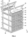
- FIG. 8 is an isometric view of a cassette having three of the blocks of FIG. 5 stacked together.
- FIG. 9 is a section in elevation view of the cassette of FIG. 8 in a tank.
- FIG. 10 is an elevation view of an aerator.
- FIG. 11 is a cross section of the aerator of FIG. 10 .
- FIG. 12 is a graph of TMP over time for a module 20 that is beginning to sludge.
- FIG. 1 shows a membrane sheet 10 .
- the membrane sheet 10 is made up of two substrate sheets 12 formed and bonded together to provide internal channels 14 .
- the outsides of the substrate sheets 12 are coated with a porous separation layer 16 .
- the separation layer 16 may be made by casting a membrane forming dope over the substrate sheets 12 and then curing the dope in a quench bath. This produces pores according to the non-solvent induced phase separation (NIPS) method, typically in the ultrafiltration or microfiltration range.
- NIPS non-solvent induced phase separation
- a central sheet 18 between the two substrate sheets 12 is optional but may be added to provide a more rigid membrane sheet 10 if desired.
- the example of a membrane sheet 10 shown has substrate sheets 12 made from non-woven polyethylene terephthalate (PET) sheets molded above their heat deflection temperature to provide free standing ridges.
- the separation layer 16 is a polyvinylidene fluoride (PVDF) based ultrafiltration (UF) membrane with a molecular weight cut off (MWCO) of about 100 kDalton. Its clean water permeability is about 25 gfd/psi @20C and 90 gfd flux.
- PVDF polyvinylidene fluoride
- UF ultrafiltration
- Its clean water permeability is about 25 gfd/psi @20C and 90 gfd flux.
- FIG. 2 shows a membrane module 20 .
- the module 20 has one or more membrane sheets 10 .
- the edges of the membrane sheets 10 that are open to the internal channels 14 i.e. the edge shown in FIG. 1 ) are potted in headers 22 , alternatively called potting heads or permeate collectors.
- headers 22 When in use, the headers 22 are oriented generally vertically and the internal channels 14 are generally horizontal. Suction applied to permeate ports 24 of the headers 22 for example by pump or siphon causes permeate 26 to be produced in the internal channels 14 and flow through the headers 22 . Optionally, permeate can be withdrawn from one or both ends of the membrane sheet 10 .
- a module 20 typically has multiple parallel membrane sheets 10 . Adjacent membrane sheets 10 are separated by vertical gaps of generally equal width.
- a module 20 is about 1900 mm wide, about 800 mm high and about 60 mm thick and contains 16 membrane sheets 10 spaced generally equally across its thickness.
- the headers 22 are polvinyl chloride (PVC) moldings and the membrane sheets 10 are potted in the headers 22 with a thermosetting epoxy resin.
- a tank holding the module 20 When used in a membrane bioreactor (MBR), a tank holding the module 20 is typically filled with mixed liquor according to an activated sludge process.
- the membrane module 20 and tank replaces the secondary clarifier. Bubbles 28 provided from below the module 20 help or cause mixed liquor 30 to flow upwards through the module 20 , including through the gaps between adjacent membrane sheets 10 .
- the module 20 may be used to filter surface water to provide potable water.
- the surface water may have a coagulant and/or flocculant added to it.
- the module 20 may be immersed in water containing flocs.
- FIG. 3 shows a schematic view of a module 20 cut open to further illustrate the flow of mixed liquor 30 (or another feed liquid) through the module 20 .
- the undulating shape of the membrane sheets 10 creates turbulence in the mixed liquor 30 as it rises.
- the membrane sheets 10 vibrate as the mixed liquor 30 and bubbles 28 move between them.
- the bubbles 28 may provide some direct scouring of the membrane sheets 10 in addition to assisting or causing the mixed liquor flow.
- the position of the headers 22 at the sides of the module 20 provides a generally unobstructed path for bubbles 28 and mixed liquor 30 to flow through the module 20 .
- sludging can still occur under certain conditions. If sludging does occur, these features are also believed to help the module 20 to release sludge built up within the module 20 .
- FIG. 4 shows a stack 32 of three modules 20 .
- the modules 20 are stacked vertically on top of each other.
- the permeate ports 24 of a lower module fit into sockets (not visible) in the headers 22 of an upper module.
- the sockets in the lowest module 20 are plugged.
- the permeate ports 24 of the highest module can be connected to a permeate withdrawal pipe and used to withdraw permeate from all three modules 20 .
- Stacks 32 may also be made with two, four or other numbers of modules 20 . Since the headers 22 of adjacent modules are vertically aligned and continuous, feed liquid can flow vertically through the entire stack 32 without being impeded by the headers 22 .
- FIG. 5 shows a block 40 containing a plurality of modules 20 in a frame 42 .
- the modules 20 are placed side by side in the frame 42 .
- a module 20 may slide vertically into or out of the frame 42 .
- the headers 22 of the module 20 fit into corresponding slots 44 provided, in the example shown, by plastic moldings attached to the frame 42 .
- the frame 42 is preferably made of stainless steel, although other materials may also be used.
- FIG. 6 shows an enlarged view of the top of a block 40 .
- a flange 46 at the top of the block 40 and a similar flange (not shown in FIG. 6 ) on the bottom of the block 40 can be used to support an upper or lower block 40 and to allow blocks 40 in a stack to be fastened together.
- the permeate ports 24 of the modules 20 protrude above the flange 46 to allow for permeate connection between modules 20 in a stack as described in FIG. 4 .
- FIG. 7 shows an enlarged view of a horizontal section of part of the block 40 .
- the header 22 contains a permeate chamber 23 defined by the header 22 , the edges of the membrane sheets 10 and the potting resin 27 between the membrane sheets 10 .
- the permeate chamber 23 is in fluid communication with the permeate ports 24 and sockets.
- a bolt 48 passes through the frame 42 and is threaded into a nut 25 adhered to the header 22 , or molded integrally with the plastic molded header 22 as shown.
- FIG. 8 shows a cassette 50 made up of three blocks 40 stacked vertically together, one on top of the other.
- a cassette 50 made have one, two, four or another number of bocks 40 .
- the permeate ports 24 of the upper block 40 are connected to a permeate header pipe 54 , optionally through connector pipes 52 as shown.
- the frames 42 of the blocks 40 are connected to each other by struts 58 that, in the example shown, are threaded rods with nuts on their ends. Struts 58 also attach the upper block 40 to a cassette frame 56 , which may be used to hang the cassette 50 in a tank.
- Air supply pipes 60 bring air to the bottom of the cassette to be fed to a set of aerators (not visible) under the lowest block 40 .
- FIG. 9 shows a cassette 50 installed in a tank 70 .
- the tank 70 shown is a concrete tank cast in the ground.
- tanks made of metal, plastic or other materials, in or above the ground, may be used.
- the cassette frame 56 rests on the walls of the tank 70 , in particular on ledges 72 attached to the tank 70 in the example shown.
- the cassette 50 can be lowered into the tank 70 , or lifted out of the tank 70 , by a crane or hoist attached to the cassette frame 56 .
- Adjustable plates (not shown) may be added to the ledges 70 or cassette from 56 to allow the cassette 50 to be leveled in the tank 70 .
- the cassette 50 can rest on the bottom of the tank 70 , or the cassette 50 can be attached to a frame or other structure that rests on the bottom of tank 70 .
- the tank 70 preferably surrounds the cassette 50 closely as shown.
- Mixed liquor or other feed liquid
- This arrangement provides an average upwards flow of feed liquid through the modules 20 .
- Multiple cassettes 50 can be spaced along the length of the tank 70 and combined to make a membrane train.
- a complete membrane system may have one or more trains.
- the air supply pipes 60 extend horizontally below the cassette 50 .
- the horizontal part of each air supply pipe 60 has a series of holes, one located below each vertical stack of 1-5 modules 20 .
- a plurality of aerators 80 (not visible in FIG. 9 but shown in FIGS. 10 and 11 ), preferably one for each vertical stack of modules 20 , are attached to the frame 42 of the lowest block 40 and extend across the bottom of the cassette 50 perpendicular to and above the horizontal parts of the air supply pipes 60 .
- the aerators 80 are open bottomed channels and receive air that rises upwards from holes in the air supply pipes 60 below them.
- the aerators 80 are parallel to the modules 20 .
- the cassette 50 has 84 modules 20 .
- each module 20 is about 7-10 cm wide.
- the modules 20 may be arranged in a vertical stack from 1 to 5 modules 20 high in a cassette 50 .
- Each stack of modules 20 in the cassette 50 has one aerator 80 about 3-6 cm wide below the lowest module 20 in the stack.
- FIGS. 10 and 11 show an aerator 80 .
- the aerator 80 shown is made from a stainless steel plate bent to form a prismatic open bottomed channel.
- the aerator 80 may have a simple triangular shape as shown in FIG. 11 or another shape.
- Holes 82 in the aerator 80 produce bubbles when the aerator 80 is in use.
- bubbles are provided essentially continuously, but optionally at a varying rate, while permeate is withdrawn from the modules 20 and during backwashing or relaxation periods.
- Each aerator 80 is general parallel to and directly below its corresponding module 20 .
- the aerator 80 receives air (or another gas) rising upwards from the air supply pipes 60 .
- End plates 86 prevent air from escaping from the ends of the aerator 80 .
- the holes 82 may be, for example, between 3 mm and 8 mm in diameter and produce medium size bubbles of about 5 to 10 mm in diameter.
- an air-water interface 88 within the aerator tends to rise towards the center of the aerator 80 .
- the holes 82 may similarly rise away from the source of the air, in this case towards the center of the aerator 80 .
- the holes 82 may be arranged differently, but still providing an uneven distribution of holes 82 along the length of the aerator 82 , preferably with an increased density of holes away from the air supply pipes 60 .
- the two outer thirds or quarters of the aerator 82 may contain more holes 82 per unit length of aerator 80 than the middle third or half.
- a centrally concentrated arrangement of holes 82 is preferred.
- the uneven distribution of holes 82 produces a generally even distribution of air across the length of a module 20 .
- the holes 82 can also be arranged to bias the air towards the ends of a module 20 or the center of a module 20 .
- bubbles released from the aerators 80 pass between membrane sheets 10 .
- the primary purpose of the bubbles is to vibrate the membrane sheets 10 .
- the bubbles may also directly scour the membrane sheets and cause feed liquid to rise through the modules 20 .
- the rising feed liquid further scours and vibrates the membranes sheets 10 , and also renews and de-concentrates the feed liquid between membrane sheets 10 .
- a higher air flow rate generally causes an increased rate of feed liquid flow through the module 20 , increased membrane sheet vibration 10 , and increased scouring of the membrane surface.
- One or more of these effects is believed to discourage sludge buildup in the modules 20 , for example by discouraging membrane sheets 10 from touching each other for extended periods of time.
- the influent feed rate may vary causing the required total permeate production rate and membrane flux to also vary. Further, a plant operator may choose to, or be required to, take a membrane train out of production temporarily and to compensate for the lost production by increasing the flux of the remaining trains. In an aeration regime, the rate of air supplied to a module 20 is increased with increasing flux and decreased with decreasing flux.
- a table or formula correlating average air flow rate to flux can be developed by operating at a series of flux values and recording the air flow rate that provides stable transmembrane pressure (TMP) at each flux. In experiments with modules 20 as described above in one MBR, the TMP was stable a flux of 16 GFD flux at 10° C.
- low-pressure positive displacement air blowers driven by a variable frequency drive are used to supply air to the aerators 80 .
- the air flow rate may be varied by altering the blower speed.
- the air-flow rate may be varied to provide a higher or lower average air flow rate.
- the air flow rate may also be varied to provide a continuously variable flow rate, varying around a specified average flow rate.
- a controller can provide a random variation in air flow rate, varying around a specified average flow rate.
- the air flow rate may be varied by modulating a valve in the intake or outlet of the blower.
- Air flow rate can also be varied by turning one or more blowers in a set of blowers on or off.
- backwashing is done at between 25% and 125% of the permeation flux preceding the backwashing event.
- backwashing is done at not more than the flux in the permeation interval preceding the backwashing event, for example at between 25% and 75% of the permeation flux in the preceding interval.
- permeation intervals and backwashing events before and after the flux change can be scaled to each other or otherwise mathematically normalized to permit monitoring and control methods, to be described further below, to continue across a flux change.
- a control system monitors the trans-membrane pressure (TMP) across a module 20 (or larger or smaller grouping of membrane sheets 10 ).
- TMP can be calculated by comparing the reading from a pressure sensor on the permeate side of the module 20 to the static head of water at the same elevation on the feed side of the module 20 and making an allowance for head loss in the permeate piping between the module 20 and pressure sensor.
- a pressure-indicating transmitter sends a signal indicating the measured pressure to a programmable logic control (PLC) or other data logging, computing or control device.
- PLC programmable logic control
- the operator is able, or the PLC is programmed to be able, to detect when the membrane is being fouled, or when the membrane is being sludged, or both.
- Sludging of the membranes involves solids accumulating on the outside of the membrane surface over multiple permeation intervals. This can follow concentration polarization but the distinguishing feature of sludging is that the amount of solids still present after backwashing (or another cleaning procedure such as relaxation or increased aeration, or a combination of backwashing or relaxation with increased aeration) increases from one permeation interval to the next. Thus sludging indicates a failure of the regular cleaning procedure to substantially disperse or dilute the concentration polarization layer on the surface of the membrane or in the pores such that solids are deposited the surface of the membranes between permeation intervals. If left un-corrected, a thick layer of solids will accumulate and may dewater, usually in a certain portion of the membrane sheet 10 , eventually blocking the filtration area of the membrane in the region of the sludging.
- Membrane fouling when discussed in general, can include sludging and solids accumulation on the surface of the membranes.
- fouling is used to refer primarily to other permeability-reducing phenomenon such solids entering the pores of the membranes or chemical scaling, bonding or precipitation. Both of fouling and sludging reduce the performance of the membranes but require different processes to remove them.
- the TMP of one or more membrane sheets 10 is monitored over a series of permeation intervals each separated by a cake layer removing procedure.
- the membrane sheets 10 will be described as a module 20 , although larger or smaller (typically larger) groups of membrane sheets 10 may be controlled as one unit.
- the cake layer removing procedure will be a backwash although a different cake layer removing procedure could be used.
- the monitoring (and other process steps) will be described as implemented by a PLC although the operator or another control device could be used.
- a material increase in TMP during permeation over time without a material increase in TMP during backwashing, or that the rate of increase in TMP during permeation exceeds the rate of increase in TMP during backwashing indicates sludging.
- a material increase in TMP during backwashing over time or that the rate of increase in TMP during permeation is near the rate of increase in TMP during backwashing, indicates fouling.
- a control method when sludging is detected a de-sludging procedure is implemented.
- fouling is detected, a de-fouling procedure is implemented.
- the absolute values of TMPs are compared such that the calculated difference ignores the change in direction of water flow between backwashing and permeate production.
- a turbidity meter or other indicator of membrane integrity is also monitored to verify that a change in TMP is not the result of a broken membrane or other leak in the system.
- TMP during production is sensitive to the early stages of sludging, whereas TMP during backwashing is not. Without intending to be limited by theory, it requires a higher TMP to permeate water through the membranes in the early stages of sludging because the solids are compressed and physically block the water from reaching the membrane. During backwashing, the TMP is less affected because the solids are expanded. When there is no sludging, the solids are expanded and substantially removed during a backwash and TMP in the next permeation interval does not increase.
- the PLC continuously monitors the TMP during permeation intervals and backwash intervals (alternatively called production mode and backwash mode).
- the TMP is monitored within a moving time window, for example ranging from 1 hour to 1 week preceding the current time.
- the specific duration of monitoring window is a set point that is adjustable by the operator.
- the PLC may calculate and monitor a gap for each permeation interval between i) the TMP during the permeation interval, for example as recorded at one or more selected times within each permeation interval, and ii) the TMP during backwash, either the backwash preceding the permeation interval or the backwash following the permeation interval.
- the PLC may monitor the trend in the TMPs measured during the permeation intervals and the trend in the TMPs measured during the backwashes.
- the PLC may monitor both the gap and trends.
- the operator enters set-points into the PLC for the duration of the moving window, a threshold value for TMP increase during production and a threshold value for TMP increase during backwashing. If the TMP during production for a module 20 increases by more than the threshold during the window, but the TMP during backwash for that module 20 does not increase by more than the threshold during the window, an alarm is triggered notifying the operator that the onset of sludging is likely occurring. At this time, the operator or the PCL may stop production mode and enter into an in situ de-sludging process for the module 20 .
- the PLC detects that both the TMP during production has increased by more than the threshold during the monitoring window, and the TMP during backwashes has also increased by more than the threshold during the monitoring window, an alarm is triggered notifying that fouling is likely occurring.
- the operator or the PLC may implement a de-fouling procedure, for example a chemical cleaning. If the PLC detects that TMP during backwash has increased by more than the threshold during the monitoring window, but TMP during production has not increased by more than the threshold, an alarm is triggered indicating that there may be air trapped in the permeate piping, or biological growth could be occurring in the permeate side of the system.
- the operator or the PLC may then implement a priming procedure wherein the system's air ejector will purge air from the permeate piping.
- the system's air ejector will purge air from the permeate piping.
- no effect is shown on TMP during production.
- the system is backwashing air can be forced into the membranes from the inside and block the path for water to be backwashed through the membranes. This causes the TMP during a backwash to increase.
- backwashing is done at about one third of the permeation flux. Since flux is constant during permeation (at least over the time period covered by FIG. 12 ) and constant (through at a different value) throughout the backwashing events, TMP shown in FIG. 12 is proportional to membrane permeability. The duration of the backwashing events in FIG. 12 relative to the permeation periods is exaggerated in FIG. 12 for the purposes of illustration.
- the TMP required to produce the preselected flux through the membranes is measured at time 90 before the backwash, time 92 during the backwash and time 94 after the backwash. TMP is recorded as its absolute value, i.e. regardless of the direction of flow.
- TMP is recorded as its absolute value, i.e. regardless of the direction of flow.
- one or both of two differences are calculated, firstly the difference between TMP before and after backwash (i.e. 90 - 92 ) and secondly the difference between TMP during (for example in about the middle of) and after the backwash (i.e. 94 - 92 ).
- the after backwash TMP is preferably recorded a few seconds after permeation resumes, or when the TMP reading stabilizes, since the TMP immediately after backwash resumes may change rapidly and be dominated by transient conditions. In both cases, taking the absolute value of the difference allows for either TMP to be subtracted from the other or for permeability to be used in place of TMP even though permeability is inversely related to TMP.
- the first five backwash events from the left indicate generally stable operation. Neither of the two differences mentioned above varies over a period of time (for example from one backwash to another or a longer period of time such as the five preceding permeation intervals) by more than a threshold amount, for example a threshold value in the range of 10-20% of an average value (for example averaged over the five preceding permeation intervals or a long term average), or by a threshold value in the range of 10-20% of the typical clean water permeability (or permeability during backwash) of the membrane. Depending on how the membranes are operated, other threshold values may be appropriate.
- a threshold value in the range of 10-20% of an average value for example averaged over the five preceding permeation intervals or a long term average
- a threshold value in the range of 10-20% of the typical clean water permeability (or permeability during backwash) of the membrane may be appropriate.
- TMP 6 is exaggerated.
- a rise in TMP during a production interval (or increase in the difference between before backwash TMP and during backwash TMP without a corresponding increase in the difference between after backwash TMP and during backwash TMP) can indicate that the process is approaching the critical flux (alternatively called critical flux).
- critical flux alternatively called critical flux
- the average air flow rate during permeation may be increased to inhibit fouling.
- the sixth and further backwashes suggest the onset of sludging in the module. This is indicated by one or both differences mentioned above exceeding the threshold amounts. Using both differences to indicate the onset of sludging helps reduce false positive indications, for example as caused by air accumulating on the permeate side of the membranes. Mathematically related indicators can also be used. Alternatively, the onset of sludging can be detected by visually observing trends in TMP or permeability over time or by providing mathematically similar analysis. For example, in FIG. 12 , the onset of sludging is indicated by relatively sudden rises in one or both of the before and after backwash TMP while TMP during backwash remains relatively stable, as determined for example with a moving window as described above.
- Combinations of indicators may also be used.
- the onset of sludging may be suggested by a rise beyond a threshold value in one of the differences described above during a moving window, but confirmed only if the rise in TMP during backwash in that window did not exceed the threshold value.
- a de-sludging process is applied to the relevant modules 20 .
- permeation is stopped while aeration continues, preferably at an increased or maximum available rate.
- the de-sludging process may last for a short period of time, for example 1 to 5 minutes, or for a longer period of time, for example 5 minutes to one week, or for 1 hour to 24 hours.
- the de-sludging process dissipates solids starting to collect in the modules 20 before irreversible sludging occurs.
- the inventors believe that the modules 20 described above are particularly robust in that significant solids build-ups can be dissipated. However, it is expected that the method of detecting and reversing the onset of sludging can still be applied to other module designs with appropriate reductions in the threshold values, particularly if the backwash flux rate is not more than the production rate flux. The method might also be applied to modules operating with outside in flow in closed vessels.
Landscapes
- Chemical & Material Sciences (AREA)
- Chemical Kinetics & Catalysis (AREA)
- Engineering & Computer Science (AREA)
- Water Supply & Treatment (AREA)
- Separation Using Semi-Permeable Membranes (AREA)
Abstract
Description
Claims (17)
Priority Applications (1)
| Application Number | Priority Date | Filing Date | Title |
|---|---|---|---|
| US15/274,520 US11045768B2 (en) | 2015-09-24 | 2016-09-23 | Method of operating membrane filter |
Applications Claiming Priority (2)
| Application Number | Priority Date | Filing Date | Title |
|---|---|---|---|
| US201562232018P | 2015-09-24 | 2015-09-24 | |
| US15/274,520 US11045768B2 (en) | 2015-09-24 | 2016-09-23 | Method of operating membrane filter |
Publications (2)
| Publication Number | Publication Date |
|---|---|
| US20170095773A1 US20170095773A1 (en) | 2017-04-06 |
| US11045768B2 true US11045768B2 (en) | 2021-06-29 |
Family
ID=58385441
Family Applications (1)
| Application Number | Title | Priority Date | Filing Date |
|---|---|---|---|
| US15/274,520 Active 2038-05-13 US11045768B2 (en) | 2015-09-24 | 2016-09-23 | Method of operating membrane filter |
Country Status (2)
| Country | Link |
|---|---|
| US (1) | US11045768B2 (en) |
| WO (1) | WO2017049408A1 (en) |
Families Citing this family (3)
| Publication number | Priority date | Publication date | Assignee | Title |
|---|---|---|---|---|
| CA3104749A1 (en) | 2018-07-03 | 2020-01-09 | Fibracast Ltd. | Tightly spaced flat sheet immersed membranes and fine bubble aeration |
| AU2019456757A1 (en) | 2019-07-16 | 2022-02-10 | Fibracast Ltd. | System and method for feeding immersed membrane units |
| US11492273B2 (en) * | 2020-11-02 | 2022-11-08 | Ovivo Inc. | Membrane module manifold with integrated end caps |
Citations (16)
| Publication number | Priority date | Publication date | Assignee | Title |
|---|---|---|---|---|
| US2415048A (en) * | 1943-04-19 | 1947-01-28 | Sharp William | Equipment for treating sewage |
| US2917295A (en) * | 1956-08-29 | 1959-12-15 | American Well Works | Diffuser |
| US3294380A (en) * | 1963-10-04 | 1966-12-27 | American Well Works | Solid dome diffuser with trap |
| US3608834A (en) * | 1968-08-30 | 1971-09-28 | David S Maclaren | Gas diffuser |
| US3997634A (en) * | 1973-10-09 | 1976-12-14 | Downs Ernest W | Diffuser assembly |
| US4861472A (en) * | 1988-07-14 | 1989-08-29 | Smith & Loveless, Inc. | Apparatus for filtration of a suspension |
| US5639373A (en) | 1995-08-11 | 1997-06-17 | Zenon Environmental Inc. | Vertical skein of hollow fiber membranes and method of maintaining clean fiber surfaces while filtering a substrate to withdraw a permeate |
| US5944997A (en) * | 1995-08-11 | 1999-08-31 | Zenon Environmental Inc. | System for maintaining a clean skein of hollow fibers while filtering suspended solids |
| WO2000013767A1 (en) | 1998-09-09 | 2000-03-16 | Pall Corporation | Fluid treatment elements, methods for cleaning fluid treatment elements and methods for treating fluids |
| US6287467B1 (en) | 2000-02-04 | 2001-09-11 | Kubota Corporation | Submerged membrane cartridge |
| WO2007006153A1 (en) | 2005-07-12 | 2007-01-18 | Zenon Technology Partnership | Process control for an immersed membrane system |
| WO2007079540A1 (en) | 2006-01-12 | 2007-07-19 | Siemens Water Technologies Corp. | Improved operating strategies in filtration processes |
| US20070261554A1 (en) * | 2006-05-15 | 2007-11-15 | Generon Igs, Inc. | Air separation membrane module with variable sweep stream |
| US20090101569A1 (en) * | 2007-10-21 | 2009-04-23 | Fuji Electric Systems Co., Ltd. | Sludge filtration apparatus and filter assembly thereof |
| WO2011130853A1 (en) | 2010-04-20 | 2011-10-27 | Fibracast Ltd. | Formed sheet membrane element and filtration system |
| WO2013056373A1 (en) | 2011-10-20 | 2013-04-25 | Fibracast Ltd. | Coating device and process for coating formed sheet membrane element |
-
2016
- 2016-09-23 US US15/274,520 patent/US11045768B2/en active Active
- 2016-09-23 WO PCT/CA2016/051118 patent/WO2017049408A1/en active Application Filing
Patent Citations (16)
| Publication number | Priority date | Publication date | Assignee | Title |
|---|---|---|---|---|
| US2415048A (en) * | 1943-04-19 | 1947-01-28 | Sharp William | Equipment for treating sewage |
| US2917295A (en) * | 1956-08-29 | 1959-12-15 | American Well Works | Diffuser |
| US3294380A (en) * | 1963-10-04 | 1966-12-27 | American Well Works | Solid dome diffuser with trap |
| US3608834A (en) * | 1968-08-30 | 1971-09-28 | David S Maclaren | Gas diffuser |
| US3997634A (en) * | 1973-10-09 | 1976-12-14 | Downs Ernest W | Diffuser assembly |
| US4861472A (en) * | 1988-07-14 | 1989-08-29 | Smith & Loveless, Inc. | Apparatus for filtration of a suspension |
| US5639373A (en) | 1995-08-11 | 1997-06-17 | Zenon Environmental Inc. | Vertical skein of hollow fiber membranes and method of maintaining clean fiber surfaces while filtering a substrate to withdraw a permeate |
| US5944997A (en) * | 1995-08-11 | 1999-08-31 | Zenon Environmental Inc. | System for maintaining a clean skein of hollow fibers while filtering suspended solids |
| WO2000013767A1 (en) | 1998-09-09 | 2000-03-16 | Pall Corporation | Fluid treatment elements, methods for cleaning fluid treatment elements and methods for treating fluids |
| US6287467B1 (en) | 2000-02-04 | 2001-09-11 | Kubota Corporation | Submerged membrane cartridge |
| WO2007006153A1 (en) | 2005-07-12 | 2007-01-18 | Zenon Technology Partnership | Process control for an immersed membrane system |
| WO2007079540A1 (en) | 2006-01-12 | 2007-07-19 | Siemens Water Technologies Corp. | Improved operating strategies in filtration processes |
| US20070261554A1 (en) * | 2006-05-15 | 2007-11-15 | Generon Igs, Inc. | Air separation membrane module with variable sweep stream |
| US20090101569A1 (en) * | 2007-10-21 | 2009-04-23 | Fuji Electric Systems Co., Ltd. | Sludge filtration apparatus and filter assembly thereof |
| WO2011130853A1 (en) | 2010-04-20 | 2011-10-27 | Fibracast Ltd. | Formed sheet membrane element and filtration system |
| WO2013056373A1 (en) | 2011-10-20 | 2013-04-25 | Fibracast Ltd. | Coating device and process for coating formed sheet membrane element |
Non-Patent Citations (3)
| Title |
|---|
| Definition of "horizontal section", Merriam Webster Online Dictionary, Accessed Apr. 23, 2020, pp. 1-5. (Year: 2020). * |
| International Patent Application No. PCT/CA2016/051118, International Search Report and Written Opinion dated Dec. 19, 2016. |
| Liu, Xuefei et al., "CFD modelling of uneven flows behaviour in flat-sheet membrane bioreactors: From bubble generation to shear stress distribution", Journal of Membrane Science 570-571 (2019) 146-155. |
Also Published As
| Publication number | Publication date |
|---|---|
| US20170095773A1 (en) | 2017-04-06 |
| WO2017049408A1 (en) | 2017-03-30 |
Similar Documents
| Publication | Publication Date | Title |
|---|---|---|
| EP1140330B1 (en) | Water filtration using immersed membranes | |
| US20060065596A1 (en) | Membrane filter cleansing process | |
| USRE42669E1 (en) | Vertical cylindrical skein of hollow fiber membranes and method of maintaining clean fiber surfaces | |
| KR100921878B1 (en) | Hollow fiber membrane cartridge | |
| US20080203019A1 (en) | Membrane batch filtration process | |
| US20070051679A1 (en) | Water filtration using immersed membranes | |
| US10279316B2 (en) | Closed loop membrane filtration system and filtration device | |
| US11045768B2 (en) | Method of operating membrane filter | |
| WO2005082498A1 (en) | Water filtration using immersed membranes | |
| JP2009537317A (en) | Ventilation device for a water filtration system with a submerged membrane, comprising a floor provided with means for injecting gas and at least one pressure balance system | |
| KR20150099534A (en) | Multi-stage immersion-type membrane separation device and membrane separation method | |
| KR100993886B1 (en) | Method of operating membrane separator | |
| KR20130082363A (en) | Membrane module using hallow fiber | |
| WO2004112944A1 (en) | Membrane cartridge, membrane separating device, and membrane separating method | |
| US20050224412A1 (en) | Water treatment system having upstream control of filtrate flowrate and method for operating same | |
| JP6036808B2 (en) | Fresh water generation method | |
| JP4437527B2 (en) | Membrane filtration module | |
| JP4046661B2 (en) | Wastewater treatment method | |
| US20230121715A1 (en) | Method and program for determining cleaning trouble in fresh water generator | |
| AU2016247809B2 (en) | Conversion of media filter into membrane gravity filter | |
| JP7213711B2 (en) | Water treatment device and water treatment method | |
| JP4853454B2 (en) | Removal method of filtration membrane element | |
| CA2560152A1 (en) | Water filtration using immersed membranes | |
| JP2000084370A (en) | Membrane separation device and its operation | |
| Lei | Impact of hydrodynamic conditions and membrane configuration on the permeate flux in submerged membrane systems for drinking water treatment |
Legal Events
| Date | Code | Title | Description |
|---|---|---|---|
| STPP | Information on status: patent application and granting procedure in general |
Free format text: NON FINAL ACTION MAILED |
|
| STPP | Information on status: patent application and granting procedure in general |
Free format text: RESPONSE TO NON-FINAL OFFICE ACTION ENTERED AND FORWARDED TO EXAMINER |
|
| STPP | Information on status: patent application and granting procedure in general |
Free format text: FINAL REJECTION MAILED |
|
| STPP | Information on status: patent application and granting procedure in general |
Free format text: NON FINAL ACTION MAILED |
|
| STPP | Information on status: patent application and granting procedure in general |
Free format text: NOTICE OF ALLOWANCE MAILED -- APPLICATION RECEIVED IN OFFICE OF PUBLICATIONS |
|
| STPP | Information on status: patent application and granting procedure in general |
Free format text: DOCKETED NEW CASE - READY FOR EXAMINATION |
|
| STPP | Information on status: patent application and granting procedure in general |
Free format text: NON FINAL ACTION MAILED |
|
| AS | Assignment |
Owner name: FIBRACAST LTD., CANADA Free format text: ASSIGNMENT OF ASSIGNORS INTEREST;ASSIGNOR:TOMESCU, IONEL JOHN;REEL/FRAME:055904/0854 Effective date: 20210412 |
|
| STPP | Information on status: patent application and granting procedure in general |
Free format text: RESPONSE TO NON-FINAL OFFICE ACTION ENTERED AND FORWARDED TO EXAMINER |
|
| STPP | Information on status: patent application and granting procedure in general |
Free format text: NOTICE OF ALLOWANCE MAILED -- APPLICATION RECEIVED IN OFFICE OF PUBLICATIONS |
|
| STPP | Information on status: patent application and granting procedure in general |
Free format text: PUBLICATIONS -- ISSUE FEE PAYMENT RECEIVED |
|
| STPP | Information on status: patent application and granting procedure in general |
Free format text: PUBLICATIONS -- ISSUE FEE PAYMENT VERIFIED |
|
| STCF | Information on status: patent grant |
Free format text: PATENTED CASE |