KR20180098980A - Lamp for vehicle - Google Patents
Lamp for vehicle Download PDFInfo
- Publication number
- KR20180098980A KR20180098980A KR1020170025859A KR20170025859A KR20180098980A KR 20180098980 A KR20180098980 A KR 20180098980A KR 1020170025859 A KR1020170025859 A KR 1020170025859A KR 20170025859 A KR20170025859 A KR 20170025859A KR 20180098980 A KR20180098980 A KR 20180098980A
- Authority
- KR
- South Korea
- Prior art keywords
- air
- lamp
- lamp housing
- vehicle
- light emitting
- Prior art date
- Legal status (The legal status is an assumption and is not a legal conclusion. Google has not performed a legal analysis and makes no representation as to the accuracy of the status listed.)
- Withdrawn
Links
Images


Classifications
-
- F—MECHANICAL ENGINEERING; LIGHTING; HEATING; WEAPONS; BLASTING
- F21—LIGHTING
- F21S—NON-PORTABLE LIGHTING DEVICES; SYSTEMS THEREOF; VEHICLE LIGHTING DEVICES SPECIALLY ADAPTED FOR VEHICLE EXTERIORS
- F21S45/00—Arrangements within vehicle lighting devices specially adapted for vehicle exteriors, for purposes other than emission or distribution of light
- F21S45/30—Ventilation or drainage of lighting devices
-
- B—PERFORMING OPERATIONS; TRANSPORTING
- B01—PHYSICAL OR CHEMICAL PROCESSES OR APPARATUS IN GENERAL
- B01D—SEPARATION
- B01D46/00—Filters or filtering processes specially modified for separating dispersed particles from gases or vapours
- B01D46/42—Auxiliary equipment or operation thereof
-
- B—PERFORMING OPERATIONS; TRANSPORTING
- B60—VEHICLES IN GENERAL
- B60S—SERVICING, CLEANING, REPAIRING, SUPPORTING, LIFTING, OR MANOEUVRING OF VEHICLES, NOT OTHERWISE PROVIDED FOR
- B60S1/00—Cleaning of vehicles
- B60S1/02—Cleaning windscreens, windows or optical devices
- B60S1/56—Cleaning windscreens, windows or optical devices specially adapted for cleaning other parts or devices than front windows or windscreens
- B60S1/60—Cleaning windscreens, windows or optical devices specially adapted for cleaning other parts or devices than front windows or windscreens for signalling devices, e.g. reflectors
Landscapes
- Engineering & Computer Science (AREA)
- Mechanical Engineering (AREA)
- Chemical & Material Sciences (AREA)
- Chemical Kinetics & Catalysis (AREA)
- General Engineering & Computer Science (AREA)
- Arrangement Of Elements, Cooling, Sealing, Or The Like Of Lighting Devices (AREA)
- Non-Portable Lighting Devices Or Systems Thereof (AREA)
Abstract
본 발명은 차량용 램프에 관한 것으로서, 보다 상세하게는 차량에 장착되는 램프 조립체의 상태에 따라 통기성의 조절이 가능하게 하여 습기 발생을 방지할 수 있는 차량용 램프에 관한 것이다.
본 발명의 실시예에 따른 차량용 램프는, 램프 하우징 및 상기 램프 하우징와 결합되어 그 내부에 적어도 하나의 발광부가 수용되는 수용 공간을 형성하는 렌즈부를 포함하는 램프 조립체, 상기 램프 하우징의 일측에 형성되는 공기 유입부, 및 상기 램프 하우징의 타측에 형성되는 공기 토출부를 포함하며, 상기 공기 토출부는, 상기 램프 조립체가 제1 상태일 때 차폐되고, 상기 램프 조립체가 제2 상태일 때 개방된다.BACKGROUND OF THE INVENTION 1. Field of the Invention [0001] The present invention relates to a lamp for a vehicle, and more particularly, to a lamp for a vehicle that can adjust moisture permeability according to the state of a lamp assembly mounted on a vehicle, thereby preventing moisture from being generated.
The vehicle lamp according to an embodiment of the present invention includes a lamp assembly including a lamp housing and a lens unit coupled to the lamp housing to form a housing space in which at least one light emitting unit is received, And an air discharge portion formed on the other side of the lamp housing. The air discharge portion is shielded when the lamp assembly is in the first state, and is opened when the lamp assembly is in the second state.
Description
본 발명은 차량용 램프에 관한 것으로서, 보다 상세하게는 차량에 장착되는 램프 조립체의 상태에 따라 통기성의 조절이 가능하게 하여 습기 발생을 방지할 수 있는 차량용 램프에 관한 것이다.BACKGROUND OF THE
일반적으로 차량은 야간 주행시에 차량 주변에 위치한 대상물을 용이하게 확인하기 위한 조명 기능 및 다른 차량이나 도로 이용자들에게 차량의 주행 상태를 알리기 위한 신호 기능을 가지는 다양한 램프를 구비하고 있으며, 각 램프는 그 기능을 충분히 발휘하도록 설치 기준과 규격에 대하여 법규로 규정되어 있다.Generally, the vehicle is provided with various lamps having a lighting function for easily confirming an object located in the vicinity of the vehicle at the time of night driving and a signal function for notifying other vehicles or road users of the running state of the vehicle. It is stipulated by the regulations about installation standards and specifications so that the functions are fully demonstrated.
예를 들어, 헤드 램프 및 포그 램프 등은 주로 조명 기능을 목적으로 하며, 턴 시그널 램프, 테일 램프, 브레이크 램프 및 사이드 마커(Side marker) 등은 주로 신호 기능을 목적으로 한다.For example, head lamps and fog lamps are mainly intended for lighting functions, and turn signal lamps, tail lamps, brake lamps and side markers are mainly used for signal functions.
이러한 차량용 램프는 내부 및 외부 사이의 온도 차이로 인하여 차량용 램프 내부에 존재하는 습기에 의해 렌즈 표면에 물방울이나 김서림 등이 발생하는 경우 충분한 시야를 확보하기 어려워 차량 사고가 발생할 가능성이 있기 때문에 차량용 램프의 내부 및 외부 사이의 공기를 순환시킴으로써 내부 온도나 습도가 적정하게 유지되도록 할 필요가 있다.Such a vehicular lamp has a problem in that it is difficult to secure a sufficient field of view when water droplets or fogging occurs on the surface of the lens due to the moisture present inside the lamp due to the temperature difference between the inside and the outside, It is necessary to circulate the air between the inside and the outside so that the internal temperature and humidity can be appropriately maintained.
차량용 램프는 실제 차량에 장착되어 실사용되는 환경을 기준으로 물방울이나 김서림 등이 발생되지 않도록 하는 통기성을 가지도록 설계되나, 차량용 램프가 차량에 장착되기 전 장기 방치되는 상태이거나 판매 전 차량에 장착된 상태에서 장기 방치되는 경우에는 상대적으로 낮은 통기성을 가지는 편이 외부로부터 습기를 포함한 공기가 유입되는 것을 감소시켜 습기 발생을 방지하는데 유리한 면이 있다.Vehicle lamps are designed to have air permeability to prevent water droplets or fogging based on the actual environment installed in the actual vehicle. However, the vehicle lamp may be left in the vehicle for long periods before being mounted on the vehicle, There is an advantage in that moisture having a relatively low air permeability is prevented from inflow of air including moisture from the outside to prevent moisture from being generated.
따라서, 차량용 램프의 상태에 따라 통기성을 전환시킬 수 있도록 하여 습기 발생을 방지할 수 있을 뿐만 아니라 습기를 용이하게 제거할 수 있는 방안이 요구되고 있다.Accordingly, there is a demand for a method capable of preventing moisture from being generated by allowing the air permeability to be switched according to the state of a lamp for a vehicle, and for easily removing moisture.
본 발명이 해결하고자 하는 과제는 차량에 장착되는 램프 조립체의 상태에 따라 램프 조립체의 통기성을 전환시킬 수 있도록 하는 차량용 램프를 제공하는 것이다.SUMMARY OF THE INVENTION It is an object of the present invention to provide a lamp for a vehicle which can change the air permeability of the lamp assembly according to the state of the lamp assembly mounted on a vehicle.
본 발명의 과제들은 이상에서 언급한 과제로 제한되지 않으며, 언급되지 않은 또 다른 과제들은 아래의 기재로부터 당업자에게 명확하게 이해될 수 있을 것이다.The problems of the present invention are not limited to the above-mentioned problems, and other problems not mentioned can be clearly understood by those skilled in the art from the following description.
상기 과제를 달성하기 위하여 본 발명의 실시예에 따른 차량용 램프는, 램프 하우징 및 상기 램프 하우징와 결합되어 그 내부에 적어도 하나의 발광부가 수용되는 수용 공간을 형성하는 렌즈부를 포함하는 램프 조립체, 상기 램프 하우징의 일측에 형성되는 공기 유입부, 및 상기 램프 하우징의 타측에 형성되는 공기 토출부를 포함하며, 상기 공기 토출부는, 상기 램프 조립체가 제1 상태일 때 차폐되고, 상기 램프 조립체가 제2 상태일 때 개방된다.According to an aspect of the present invention, there is provided a lamp assembly for a vehicle, the lamp assembly including a lamp housing and a lens unit coupled to the lamp housing and defining a receiving space in which at least one light emitting unit is received, And an air discharge portion formed on the other side of the lamp housing, wherein the air discharge portion is shielded when the lamp assembly is in a first state, and when the lamp assembly is in a second state Is opened.
본 발명의 기타 구체적인 사항들은 상세한 설명 및 도면들에 포함되어 있다.Other specific details of the invention are included in the detailed description and drawings.
상기와 같은 본 발명의 차량용 램프에 따르면 다음과 같은 효과가 하나 혹은 그 이상 있다.The vehicle lamp of the present invention has one or more of the following effects.
램프 조립체가 차량에 장착되기 전 또는 장착된 후에 램프 조립체의 통기성을 전환시킬 수 있기 때문에 램프 조립체가 차량에 장착되어 실사용되는 경우뿐만 아니라 램프 조립체가 차량에 장착되기 전이나 실사용되기 전에도 습기 발생을 방지할 수 있는 효과가 있다.Since the lamp assembly can switch the ventilation of the lamp assembly before or after the lamp assembly is mounted on the vehicle, it is possible to prevent the lamp assembly from being wetted even before the lamp assembly is mounted on the vehicle, Can be prevented.
본 발명의 효과들은 이상에서 언급한 효과들로 제한되지 않으며, 언급되지 않은 또 다른 효과들은 청구범위의 기재로부터 당업자에게 명확하게 이해될 수 있을 것이다.The effects of the present invention are not limited to the effects mentioned above, and other effects not mentioned can be clearly understood by those skilled in the art from the description of the claims.
도 1 및 도 2는 본 발명의 실시예에 따른 차량용 램프의 외관이 도시된 사시도.
도 3은 본 발명의 실시예에 따른 차량용 램프가 도시된 개략도.
도 4 및 도 5는 본 발명의 실시예에 따른 차량용 램프의 공기 흐름이 도시된 개략도.
도 6은 본 발명의 실시예에 따른 커버부가 도시된 사시도.
도 7은 본 발명의 실시예에 따른 커버부가 설치된 램프 하우징이 도시된 개략도.
도 8은 본 발명의 실시예에 따른 커버부가 제거된 램프 하우징이 도시된 개략도.
도 9는 본 발명의 다른 실시예에 따른 커버부가 도시된 사시도.
도 10은 본 발명의 다른 실시예에 따른 커버부가 도시된 단면도.
도 11은 본 발명의 다른 실시예에 따른 커버부가 설치된 램프 하우징이 도시된 개략도.
도 12는 본 발명의 다른 실시예에 따른 커버부와 램프 하우징이 도시된 단면도.1 and 2 are perspective views showing the appearance of a lamp for a vehicle according to an embodiment of the present invention.
3 is a schematic view showing a lamp for a vehicle according to an embodiment of the present invention.
Figs. 4 and 5 are schematic diagrams showing the air flow of a lamp for a vehicle according to an embodiment of the present invention; Fig.
6 is a perspective view illustrating a cover portion according to an embodiment of the present invention.
7 is a schematic view showing a lamp housing with a cover part according to an embodiment of the present invention;
8 is a schematic view illustrating a lamp housing in which a cover is removed according to an embodiment of the present invention.
9 is a perspective view showing a cover portion according to another embodiment of the present invention.
10 is a sectional view showing a cover portion according to another embodiment of the present invention.
11 is a schematic view showing a lamp housing with a cover part according to another embodiment of the present invention.
12 is a sectional view showing a cover part and a lamp housing according to another embodiment of the present invention;
본 발명의 이점 및 특징, 그리고 그것들을 달성하는 방법은 첨부되는 도면과 함께 상세하게 후술되어 있는 실시예들을 참조하면 명확해질 것이다. 그러나 본 발명은 이하에서 개시되는 실시예들에 한정되는 것이 아니라 서로 다른 다양한 형태로 구현될 수 있으며, 단지 본 실시예들은 본 발명의 개시가 완전하도록 하고, 본 발명이 속하는 기술분야에서 통상의 지식을 가진 자에게 발명의 범주를 완전하게 알려주기 위해 제공되는 것이며, 본 발명은 청구항의 범주에 의해 정의될 뿐이다. 명세서 전체에 걸쳐 동일 참조 부호는 동일 구성 요소를 지칭한다.BRIEF DESCRIPTION OF THE DRAWINGS The advantages and features of the present invention, and the manner of achieving them, will be apparent from and elucidated with reference to the embodiments described hereinafter in conjunction with the accompanying drawings. The present invention may, however, be embodied in many different forms and should not be construed as limited to the embodiments set forth herein. Rather, these embodiments are provided so that this disclosure will be thorough and complete, and will fully convey the scope of the invention to those skilled in the art. To fully disclose the scope of the invention to those skilled in the art, and the invention is only defined by the scope of the claims. Like reference numerals refer to like elements throughout the specification.
따라서, 몇몇 실시예에서, 잘 알려진 공정 단계들, 잘 알려진 구조 및 잘 알려진 기술들은 본 발명이 모호하게 해석되는 것을 피하기 위하여 구체적으로 설명되지 않는다.Thus, in some embodiments, well known process steps, well-known structures, and well-known techniques are not specifically described to avoid an undue interpretation of the present invention.
본 명세서에서 사용된 용어는 실시예들을 설명하기 위한 것이며 본 발명을 제한하고자 하는 것은 아니다. 본 명세서에서, 단수형은 문구에서 특별히 언급하지 않는 한 복수형도 포함한다. 명세서에서 사용되는 포함한다(comprises) 및/또는 포함하는(comprising)은 언급된 구성요소, 단계, 동작 및/또는 소자 이외의 하나 이상의 다른 구성요소, 단계, 동작 및/또는 소자의 존재 또는 추가를 배제하지 않는 의미로 사용한다. 그리고, "및/또는"은 언급된 아이템들의 각각 및 하나 이상의 모든 조합을 포함한다.The terminology used herein is for the purpose of illustrating embodiments and is not intended to be limiting of the present invention. In the present specification, the singular form includes plural forms unless otherwise specified in the specification. It is to be understood that the terms comprise and / or comprise are used in a generic sense to refer to the presence or addition of one or more other elements, steps, operations and / or elements other than the stated elements, steps, operations and / It is used not to exclude. And "and / or" include each and any combination of one or more of the mentioned items.
또한, 본 명세서에서 기술하는 실시예들은 본 발명의 이상적인 예시도인 단면도 및/또는 개략도들을 참고하여 설명될 것이다. 따라서, 제조 기술 및/또는 허용 오차 등에 의해 예시도의 형태가 변형될 수 있다. 따라서, 본 발명의 실시예들은 도시된 특정 형태로 제한되는 것이 아니라 제조 공정에 따라 생성되는 형태의 변화도 포함하는 것이다. 또한 본 발명에 도시된 각 도면에 있어서 각 구성 요소들은 설명의 편의를 고려하여 다소 확대 또는 축소되어 도시된 것일 수 있다. 명세서 전체에 걸쳐 동일 참조 부호는 동일 구성 요소를 지칭한다.Further, the embodiments described herein will be described with reference to cross-sectional views and / or schematic drawings that are ideal illustrations of the present invention. Thus, the shape of the illustrations may be modified by manufacturing techniques and / or tolerances. Accordingly, the embodiments of the present invention are not limited to the specific forms shown, but also include changes in the shapes that are generated according to the manufacturing process. In addition, in the drawings of the present invention, each component may be somewhat enlarged or reduced in view of convenience of explanation. Like reference numerals refer to like elements throughout the specification.
이하, 본 발명의 실시예들에 의하여 차량용 램프를 설명하기 위한 도면들을 참고하여 본 발명에 대하여 설명하도록 한다.Hereinafter, the present invention will be described with reference to the drawings for explaining a vehicle lamp according to embodiments of the present invention.
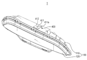
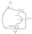
도 1 및 2는 본 발명의 실시예에 따른 차량용 램프의 외관이 도시된 사시도이고, 도 3은 본 발명의 실시예에 따른 차량용 램프가 도시된 개략도이다.1 and 2 are perspective views showing an appearance of a vehicle lamp according to an embodiment of the present invention, and Fig. 3 is a schematic view showing a lamp for a vehicle according to an embodiment of the present invention.
도 1 내지 도 3을 참조하면, 본 발명의 실시예에 따른 차량용 램프(1)는 램프 조립체(100), 공기 유입부(200), 공기 토출부(300), 커버부(400)를 포함할 수 있다.1 to 3, a
램프 조립체(100)는 일면이 개방되는 램프 하우징(110) 및 램프 하우징(110)의 개방된 일면에 결합되어 그 내부에 본 발명의 차량용 램프(1)의 용도에 적합한 빔 패턴을 형성하는 적어도 하나의 발광부(130)를 수용할 수 있는 수용 공간을 형성하는 렌즈부(120)를 포함할 수 있다.The
본 발명의 실시예에서 차량용 램프(1)는 헤드 램프, 테일 램프, 포그 램프, 턴 시그널 램프, 포지션 램프, 주간 주행 램프, 백업 램프 등과 같은 다양한 용도로 사용될 수 있으며, 각 용도에 따라 적어도 하나의 발광부(130)의 개수나 발광 색상 등은 다양하게 변경될 수 있다.In the embodiment of the present invention, the
또한, 본 발명의 실시예에서는 적어도 하나의 발광부(130)가 광원(131) 및 광원(131)으로부터 발생된 광을 렌즈부(120)로 반사시키는 리플렉터(132)를 포함하는 경우를 예를 들어 설명하나, 이에 한정되지 않고 적어도 하나의 발광부(130)는 형성하고자 하는 빔 패턴에 따라 렌즈부(120)로 입사되는 광의 일부를 차단하여 컷 오프 라인이 형성되도록 하는 쉴드 등과 같은 구성 요소를 추가적으로 더 포함할 수도 있으며, 광원(131)으로부터 발생된 광이 직접 렌즈부(120)로 진행하는 경우 리플렉터(132)가 생략될 수도 있다.In an embodiment of the present invention, at least one
이때, 적어도 하나의 발광부(130)의 광원(131)으로는 할로겐이나 HID 등과 같은 벌브가 사용되는 경우를 예를 들어 설명하기로 하나, 이는 본 발명의 이해를 돕기 위한 일 예에 불과한 것으로서, 이에 한정되지 않고 광원(131)은 LED 등과 같은 반도체 발광 소자가 사용될 수도 있으며, 광원(131)의 종류에 따라 빔 패턴을 형성하기 위한 광학계도 달라질 수 있다.Here, a case where a bulb such as a halogen lamp or a HID lamp is used as the
본 발명의 실시예에서는 적어도 하나의 발광부(130)가 복수로 구성되며 차폭 방향으로 배열되어 빔 패턴에 따라 적어도 하나로부터 광이 발생되는 경우를 예를 들어 설명하기로 한다.In an embodiment of the present invention, a case where at least one
램프 조립체(100)는 내부 및 외부 사이에 공기를 순환시켜 내부 온도를 적정하게 유지시킬 필요가 있으며, 이는 램프 조립체(100)의 내부 온도가 외부 온도에 비하여 높은 경우 램프 조립체(100) 내부 압력이 증가하여 불량이 발생하거나 램프 조립체(100) 내부에 존재하는 공기 중의 습기로 인한 물방울이나 김서림 등이 발생하여 시야가 저하되는 것을 방지하기 위함이다.The
이를 위해, 램프 조립체(100)는 상측 및 하측 중 어느 하나에는 외부 공기가 유입되는 공기 유입부(200)가 형성되고, 다른 하나에는 내부 공기가 토출되는 공기 토출부(300)가 형성될 수 있다.For this purpose, the
본 발명의 실시예에서는 대류 현상에 의해 더운 공기가 상측으로 이동하기 때문에 램프 하우징(110)의 하측에 공기 유입부(200)가 형성되고, 상측에 공기 토출부(300)가 형성되는 경우를 예를 들어 설명하기로 한다.In the embodiment of the present invention, since the hot air moves upward due to convection, the
이때, 램프 하우징(110)의 상측 및 하측은 램프 조립체(100)가 차량에 장착되는 방향을 기준으로 하는 위치로서, 램프 하우징(110)의 상측 및 하측은 램프 조립체(100)가 차량에 장착되는 방향에 따라 달라질 수 있다.The upper and lower sides of the
한편, 본 발명의 실시예에서는 적어도 하나의 발광부(130)가 복수로 구성되며 차폭 방향으로 배열되는 경우를 예를 들어 설명하고 있는데, 이 경우 공기 유입부(200)는 복수의 발광부의 배열 방향을 기준으로 일측단에 위치하는 발광부의 하측에 형성되며, 공기 토출부(300)는 타측단에 위치하는 발광부의 상측에 위치하는 것이 바람직하다.In the meantime, in the embodiment of the present invention, a case where at least one
즉, 적어도 하나의 발광부(130)가 복수로 구성되며 차폭 방향으로 배열되는 경우, 공기 유입부(200) 및 공기 토출부(300)가 동일한 발광부의 하측 및 상측에 위치할 때는 공기가 흐르는 유로가 복수의 발광부 중 어느 하나의 하측 및 상측으로 한정되기 때문에 공기가 흐르는 유로가 도 4와 같이 복수의 발광부 전체에 걸쳐 형성되도록 복수의 발광부의 배열 방향을 기준으로 공기 유입부(200)는 복수의 발광부 중 일측단에 위치하는 발광부의 하측에 형성하고 공기 토출부(300)는 복수의 발광부 중 타측단에 위치하는 발광부의 상측에 형성하는 것으로 이해될 수 있다.That is, when at least one
전술한 도 1 내지 도 3은 램프 조립체(100)에 단일의 발광부(130)가 수용되며, 그 하측 및 상측에 공기 유입부(200) 및 공기 토출부(300)가 형성된 경우의 일 예이며, 램프 조립체(100)에 복수의 발광부가 수용되는 경우 공기 유입부(200) 및 공기 토출부(300)의 위치는 달라질 수 있다.1 to 3 show an example of a case where a single
공기 유입부(200)는 외부 공기가 유입되는 벤트부(210) 및 벤트부(210)로 유입된 공기를 렌즈부(120)로 유도하는 덕트부(220)를 포함할 수 있다.The
벤트부(210)는 램프 조립체(100) 내부로 공기가 유입될 수 있는 통로의 역할을 하며, 벤트부(210)는 외부로부터 공기가 유입되는 것은 가능하게 하되, 물방울이나 이물질 등이 유입되는 것은 차단될 수 있도록 많은 수의 미세 홀이 형성될 수 있다.The
덕트부(220)는 벤트부(210)와 연통될 수 있으며, 벤트부(210)로 유입된 공기를 렌즈부(120)로 유도하는 역할을 할 수 있다.The
덕트부(220)에 의해 렌즈부(120)로 유도된 공기는 도 5와 같이 렌즈부(120) 주변에 존재하는 공기를 공기 토출부(300)로 안내할 수 있으며, 이로 인해 렌즈부(120) 주변에 존재하는 공기에 포함되는 습기로 인하여 렌즈부(120)에 물방울이나 김서림이 발생하는 것을 방지할 수 있게 된다.The air introduced into the
공기 토출부(300)는 램프 조립체(100) 내부의 공기가 외부로 토출될 수 있는 통로의 역할을 할 수 있으며, 공기 토출부(300)는 외부로 공기가 토출되는 것은 가능하게 하되, 외부로부터 이물질이나 물 등이 유입되는 것은 차단될 수 있도록 하는 소수성 필터(310)를 포함할 수 있다.The
소수성 필터(310)는 많은 수의 미세 홀이 형성되어 공기는 통과되도록 하는 반면, 외부로부터 이물질이나 물 등이 통과되는 것은 차단할 수 있으며, 이를 위해 미세 홀의 크기는 증기 상태의 물방울보다는 크며 액체 상태의 물방울보다는 작게 형성될 수 있다.The
공기 토출부(300)는 램프 하우징(110)의 경사면에 형성되는 것이 바람직한데, 이는 외부로부터 물 등이 램프 하우징(110)의 경사면을 따라 흐르도록 하여 공기 토출부(300)를 통해 램프 조립체(100)의 내부로 유입될 가능성을 줄이기 위함이다.The
이때, 공기 토출부(300)가 램프 하우징(110)의 경사면에 형성된다는 것은 소수성 필터(310)도 램프 하우징(110)의 경사면에 위치한다는 것으로 이해될 수 있다.In this case, it is understood that the
한편, 공기 토출부(300)는 램프 조립체(100)의 상태에 따라 공기 토출부(300)가 개방 또는 차폐되어 통기성이 전환될 수 있다.Meanwhile, the
예를 들어, 램프 조립체(100)가 차량에 장착되기 이전에는 공기 토출부(300)로 습기를 포함하는 공기가 유입되는 것을 줄이고, 외부로부터 이물질이나 물이 유입되는 것이 방지될 수 있도록 공기 토출부(300)가 차폐되어 저통기성을 가지게 되며, 램프 조립체(100)가 차량에 장착된 이후에는 적어도 하나의 발광부(130)로부터 광이 발생될 때 함께 발생되는 고온의 열이 신속하게 배출될 수 있도록 공기 토출부(300)가 개방되어 고통기성을 가지게 된다.For example, before the
본 발명의 실시예에서 램프 조립체(100)가 차량에 장착되기 이전에 장기 방치되는 상태이거나 램프 조립체(100)가 장착된 차량이 판매되어 실제 운전자에 의해 운행되기 이전 상태와 같이 램프 조립체(100)가 실사용되기 이전 상태를 제1 상태라 칭하고, 램프 조립체(100)가 차량이 판매되어 실제 운전자에게 운행되는 상태와 같이 램프 조립체(100)가 실사용되는 상태를 제2 상태라 칭하기로 한다.In the embodiment of the present invention, the
커버부(400)는 램프 조립체(100)의 상태에 따라 공기 토출부(300)의 저통기성이 요구되는 경우 공기 토출부(300)를 차폐시키도록 위치하고, 공기 토출부(300)의 고통기성이 요구되는 경우 공기 토출부(300)가 개방되도록 제거될 수 있다.The
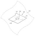
도 6은 본 발명의 실시예에 따른 커버부가 도시된 사시도이다.6 is a perspective view illustrating a cover according to an embodiment of the present invention.
도 6을 참조하면, 본 발명의 실시예에 따른 커버부(400)는 접촉부(411) 및 돌출부(412)를 포함할 수 있다.Referring to FIG. 6, the
접촉부(411)는 일면이 공기 토출부(300), 즉 소수성 필터(310)와 접촉될 수 있으며, 돌출부(412)는 접촉부(411)의 일측단으로부터 돌출되도록 형성되어 접촉부(411)를 제거하기 위한 손잡이의 역할을 할 수 있다.The
본 발명의 실시예에서 접촉부(411)는 접착 필름이나 접착 테이프의 형태로서, 일면이 공기 토출부(300)에 접착되어 공기 토출부(300)를 차폐시키도록 위치하는 경우를 예를 들어 설명하기로 한다.In the embodiment of the present invention, the
이때, 접촉부(411)에는 통기 홀(411a)이 형성될 수 있으며, 이러한 통기 홀(411a)은 공기 토출부(300)가 접촉부(411)에 의해 완전히 차폐되는 경우 공기의 순환이 이루어지지 않기 때문에 적정량의 공기 순환이 이루어지도록 하기 위함이며, 통기 홀(411a)의 크기나 개수 등은 필요에 따라 다양하게 변경될 수 있다.At this time, a
본 발명의 실시예에서 커버부(400)는 램프 조립체(100)가 제1 상태일 때는 도 7과 같이 공기 토출부(300)를 차폐시키도록 위치하여 저통기성을 가지도록 함으로써 외부로부터 습기를 포함하는 공기나 이물질 등이 유입되는 것을 줄이게 되며, 램프 조립체(100)가 제2 상태일 때는 도 8과 같이 제거되어 소수성 필터(310)가 외부로 노출되도록 함으로써 고통기성을 가지도록 하는 것이다.The
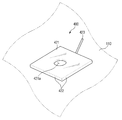
도 9는 본 발명의 다른 실시예에 따른 커버부가 도시된 사시도이고, 도 10은 본 발명의 다른 실시예에 따른 커버부가 도시된 단면도이다.FIG. 9 is a perspective view illustrating a cover according to another embodiment of the present invention, and FIG. 10 is a cross-sectional view illustrating a cover according to another embodiment of the present invention.
도 9 및 도 10을 참조하면, 본 발명의 다른 실시예에 따른 커버부(400)는 공기 토출부(300)와 일정 간격으로 이격되어 위치하는 플레이트(421), 플레이트(421)의 테두리로부터 돌출되어 형성되는 측벽부(422), 및 플레이트(421)와 측벽부(422) 중 적어도 하나로부터 연장되어 형성되는 연장부(423)를 포함할 수 있다.9 and 10, the
플레이트(421)는 적어도 공기 토출부(300)가 덮힐 수 있는 크기를 가지도록 형성될 수 있으며, 플레이트(421)는 공기 토출부(300)가 차폐된 경우 적정량의 공기가 순환될 수 있도록 하는 통기 홀(421a)을 포함할 수 있고, 통기 홀(421a)의 크기나 개수 등은 다양하게 변경될 수 있다.The
측벽부(422)는 플레이트(421)의 테두리로부터 램프 하우징(110)을 향하도록 돌출되도록 형성될 수 있다.The
본 발명의 다른 실시예에서는 도 11 및 도 12와 같이 램프 하우징(110)에 삽입 돌기(110a)가 형성되고, 측벽부(422)에 삽입 돌기(110a)가 삽입되는 삽입 홈(422a)이 형성되며, 삽입 돌기(110a)가 삽입 홈(422a)에 끼움 결합되어 커버부(400)가 공기 토출부(300)를 차폐시키도록 위치가 고정되는 경우를 예를 들어 설명하기로 하나, 이에 한정되지 않고 램프 하우징(110) 및 측벽부(422) 중 어느 하나에 삽입 돌기가 형성되고 다른 하나에 삽입 홈이 형성될 수 있다.11 and 12, an
또한, 본 발명이 다른 실시예에서는 삽입 돌기(110a) 및 삽입 홈(422a)에 의해 커버부(400)의 위치가 고정되는 경우를 예를 들어 설명하고 있으나, 이에 한정되지 않고 커버부(400)는 끼움 결합뿐만 아니라, 접착제, 후크 결합 등과 같은 다양한 결합 방식이 사용될 수 있다.Although the
연장부(423)는 커버부(400)를 램프 하우징(100)으로부터 제거하기 위한 손잡이의 역할을 할 수 있으며, 연장부(423)는 플레이트(421) 및 측벽부(422) 중 적어도 하나로부터 연장되어 형성될 수 있다.The
전술한 바와 같은 본 발명의 차량용 램프(1)는 램프 조립체(100)의 상태에 따라 공기 토출부(300)가 저통기성 또는 고통기성을 가지도록 통기성이 전환될 수 있기 때문에 습기 발생을 효과적으로 방지할 수 있게 된다.According to the
다시 말해서, 램프 조립체(100)가 차량에 장착되기 이전에 장기 방치되는 상태이거나 램프 조립체(100)가 장착된 차량이 판매 전 장기 방치되는 경우에는 커버부(400)에 의해 공기 토출부(300)가 차폐되도록 하여 저통기성을 가지도록 함으로써, 외부로부터 습기를 포함하는 공기가 유입되는 것을 방지함으로써 습기 발생 방지에 유리하게 된다.In other words, when the
또한, 램프 조립체(100)가 장착된 차량이 운행하는 경우에는 커버부(400)를 제거하여 고통기성을 가지도록 하여 고온의 열이나 습기를 포함하는 공기의 배출 성능을 향상시킬 수 있게 되는 것이다.In addition, when the vehicle on which the
본 발명이 속하는 기술분야의 통상의 지식을 가진 자는 본 발명이 그 기술적 사상이나 필수적인 특징을 변경하지 않고서 다른 구체적인 형태로 실시될 수 있다는 것을 이해할 수 있을 것이다. 그러므로 이상에서 기술한 실시예들은 모든 면에서 예시적인 것이며 한정적이 아닌 것으로 이해해야만 한다. 본 발명의 범위는 상기 상세한 설명보다는 후술하는 특허청구범위에 의하여 나타내어지며, 특허청구범위의 의미 및 범위 그리고 그 균등 개념으로부터 도출되는 모든 변경 또는 변형된 형태가 본 발명의 범위에 포함되는 것으로 해석되어야 한다.It will be understood by those skilled in the art that the present invention may be embodied in other specific forms without departing from the spirit or essential characteristics thereof. It is therefore to be understood that the above-described embodiments are illustrative in all aspects and not restrictive. The scope of the present invention is defined by the appended claims rather than the detailed description and all changes or modifications derived from the meaning and scope of the claims and their equivalents are to be construed as being included within the scope of the present invention do.
100: 램프 조립체
110: 램프 하우징
120: 렌즈부
130: 발광부
200: 공기 유입부
210: 벤트부
220: 덕트부
300: 공기 토출부
310: 소수성 필터
400: 커버부
411: 접촉부
412: 돌출부
421: 플레이트
422: 측벽부
423: 연장부100: Lamp assembly
110: Lamp housing
120:
130:
200: air inlet
210:
220: Duct part
300: air discharge portion
310: hydrophobic filter
400:
411:
412:
421: Plate
422:
423: Extension part
Claims (14)
상기 램프 하우징의 일측에 형성되는 공기 유입부; 및
상기 램프 하우징의 타측에 형성되는 공기 토출부를 포함하며,
상기 공기 토출부는,
상기 램프 조립체가 제1 상태일 때 차폐되고, 상기 램프 조립체가 제2 상태일 때 개방되는 차량용 램프.A lamp assembly including a lamp housing and a lens portion coupled to the lamp housing and defining a receiving space in which at least one light emitting portion is received;
An air inlet formed at one side of the lamp housing; And
And an air discharge unit formed on the other side of the lamp housing,
The air-
Wherein the lamp assembly is shielded when the lamp assembly is in the first state and is opened when the lamp assembly is in the second state.
상기 제1 상태는,
상기 램프 조립체가 장착된 차량이 운전자에 의해 운행되기 이전 상태이고,
상기 제2 상태는,
상기 램프 조립체가 장착된 차량이 운전자에 의해 운행되는 상태인 차량용 램프.The method according to claim 1,
Wherein the first state comprises:
A state in which the vehicle on which the lamp assembly is mounted is in a state before being operated by the driver,
The second state may comprise:
Wherein the vehicle on which the lamp assembly is mounted is operated by a driver.
상기 램프 하우징의 상측 및 하측 중 어느 하나에 상기 공기 유입부가 형성되고, 다른 하나에 상기 공기 토출부가 형성되는 차량용 램프.The method according to claim 1,
Wherein the air inlet portion is formed on one of the upper side and the lower side of the lamp housing and the air discharge portion is formed on the other.
상기 공기 유입부는,
상기 램프 하우징의 하측에 형성되고,
상기 공기 토출부는,
상기 램프 하우징의 상측에 형성되는 차량용 램프.The method of claim 3,
The air-
A lamp housing formed below the lamp housing,
The air-
Wherein the lamp is formed on the upper side of the lamp housing.
상기 적어도 하나의 발광부는,
차폭 방향으로 배열되는 복수의 발광부를 포함하며,
상기 공기 유입부는,
상기 복수의 발광부의 배열 방향을 기준으로 일측단에 위치하는 발광부의 하측에 위치하고,
상기 공기 토출부는,
상기 복수의 발광부의 배열 방향을 기준으로 타측단에 위치하는 발광부의 상측에 위치하는 차량용 램프.The method according to claim 1,
Wherein the at least one light-
And a plurality of light emitting portions arranged in the vehicle width direction,
The air-
And a light emitting portion located at one end of the light emitting portion,
The air-
Wherein the lamp is positioned above the light emitting portion located at the other end with respect to the arrangement direction of the plurality of light emitting portions.
상기 공기 유입부는,
외부 공기가 유입되는 벤트부; 및
상기 벤트부로 유입된 공기를 상기 렌즈부로 유도하는 덕트부를 포함하는 차량용 램프.The method according to claim 1,
The air-
A vent portion into which external air flows; And
And a duct portion for guiding air introduced into the vent portion to the lens portion.
상기 덕트부에 의해 유도된 공기는,
상기 렌즈부 주변에 존재하는 공기를 상기 공기 토출부로 안내하는 차량용 램프.The method according to claim 6,
The air introduced by the duct portion is supplied to the air-
And guides the air present around the lens portion to the air discharge portion.
상기 공기 토출부는,
공기를 통과시키고 외부로부터 물이 유입되는 것을 차단하는 소수성 필터를 포함하는 차량용 램프.The method according to claim 1,
The air-
And a hydrophobic filter for passing air therethrough and blocking water from entering from the outside.
상기 공기 토출부는,
상기 램프 하우징의 경사면에 형성되는 차량용 램프.The method according to claim 1,
The air-
Wherein the lamp housing is formed on an inclined surface of the lamp housing.
상기 공기 토출부를 개폐시키는 커버부를 더 포함하는 차량용 램프.The method according to claim 1,
And a cover portion for opening and closing the air discharge portion.
상기 커버부는,
적어도 하나의 통기 홀을 포함하는 차량용 램프.11. The method of claim 10,
The cover portion
A lamp for a vehicle comprising at least one ventilation hole.
상기 커버부는,
일면이 상기 공기 토출부에 접촉되도록 위치하는 접촉부; 및
상기 접촉부의 일측단으로부터 돌출되어 형성되는 돌출부를 포함하는 차량용 램프.11. The method of claim 10,
The cover portion
A contact portion positioned on one side so as to be in contact with the air discharge portion; And
And a protrusion protruding from one end of the contact portion.
상기 커버부는,
상기 공기 토출부와 일정 간격으로 이격되도록 위치하는 플레이트;
상기 플레이트의 테두리로부터 돌출되어 형성되는 측벽부; 및
상기 플레이트 및 상기 측벽부 중 적어도 하나로부터 연장되어 형성되는 연장부를 포함하는 차량용 램프.11. The method of claim 10,
The cover portion
A plate positioned to be spaced apart from the air discharge unit at a predetermined interval;
A side wall portion protruding from an edge of the plate; And
And an extension portion extending from at least one of the plate and the side wall portion.
상기 램프 하우징 및 상기 측벽부 중 어느 하나는 적어도 하나의 삽입 돌기가 형성되고, 다른 하나는 상기 적어도 하나의 삽입 돌기가 삽입되는 적어도 하나의 삽입 홈이 형성되는 차량용 램프.14. The method of claim 13,
Wherein at least one of the lamp housing and the side wall portion is formed with at least one insertion protrusion and the other has at least one insertion groove into which the at least one insertion protrusion is inserted.
Priority Applications (1)
| Application Number | Priority Date | Filing Date | Title |
|---|---|---|---|
| KR1020170025859A KR20180098980A (en) | 2017-02-28 | 2017-02-28 | Lamp for vehicle |
Applications Claiming Priority (1)
| Application Number | Priority Date | Filing Date | Title |
|---|---|---|---|
| KR1020170025859A KR20180098980A (en) | 2017-02-28 | 2017-02-28 | Lamp for vehicle |
Publications (1)
| Publication Number | Publication Date |
|---|---|
| KR20180098980A true KR20180098980A (en) | 2018-09-05 |
Family
ID=63594793
Family Applications (1)
| Application Number | Title | Priority Date | Filing Date |
|---|---|---|---|
| KR1020170025859A Withdrawn KR20180098980A (en) | 2017-02-28 | 2017-02-28 | Lamp for vehicle |
Country Status (1)
| Country | Link |
|---|---|
| KR (1) | KR20180098980A (en) |
Cited By (1)
| Publication number | Priority date | Publication date | Assignee | Title |
|---|---|---|---|---|
| US20210031732A1 (en) * | 2019-07-29 | 2021-02-04 | Ford Global Technologies, Llc | Sensor assembly with cleaning |
Citations (1)
| Publication number | Priority date | Publication date | Assignee | Title |
|---|---|---|---|---|
| JP2003257216A (en) | 2002-03-01 | 2003-09-12 | Mitsubishi Motors Corp | Vehicle exterior lamp |
-
2017
- 2017-02-28 KR KR1020170025859A patent/KR20180098980A/en not_active Withdrawn
Patent Citations (1)
| Publication number | Priority date | Publication date | Assignee | Title |
|---|---|---|---|---|
| JP2003257216A (en) | 2002-03-01 | 2003-09-12 | Mitsubishi Motors Corp | Vehicle exterior lamp |
Cited By (1)
| Publication number | Priority date | Publication date | Assignee | Title |
|---|---|---|---|---|
| US20210031732A1 (en) * | 2019-07-29 | 2021-02-04 | Ford Global Technologies, Llc | Sensor assembly with cleaning |
Similar Documents
| Publication | Publication Date | Title |
|---|---|---|
| CN103363414B (en) | Front lamp of vehicle | |
| KR101937971B1 (en) | Lamp for vehicle | |
| KR101728997B1 (en) | Ventilation of lamp module for vehicles | |
| KR101741089B1 (en) | Ventilation of lamp module for vehicles | |
| KR20180098980A (en) | Lamp for vehicle | |
| KR20150062567A (en) | Head Lamp Having Dehumidification Part for Vehicle | |
| KR20120018995A (en) | Mounting structure of moisture absorbent for head lamp | |
| JP5585230B2 (en) | Vehicle headlamp | |
| KR20140133063A (en) | Automotive lamp assembly | |
| CN100439791C (en) | Vehicle Lamps | |
| CN106461175A (en) | Ventilator and vehicle lights | |
| KR200494307Y1 (en) | Lamp for vehical | |
| KR20190002886A (en) | Lamp for vehicle | |
| JP5488208B2 (en) | Vehicle lighting | |
| KR101731779B1 (en) | Lamp for vehicle and assembling method for the same | |
| KR20160050278A (en) | A lamp apparatus for vehicles | |
| KR200499329Y1 (en) | Apparatus of dehumidifying in the lamp for vehicle | |
| US9341339B2 (en) | Lightng device having a ventilated reflector housing for motor vehicle lamp | |
| KR100410874B1 (en) | Structure for removing moisture of automobile head lamp | |
| CN105378372A (en) | Multifunctional screens for multifunctional optical units of vehicles | |
| US12584607B2 (en) | Illumination unit having an antifogging system | |
| KR200482941Y1 (en) | Automotive lamp assembly | |
| CN210511476U (en) | Light emitting device and vehicle | |
| KR20190062931A (en) | Lamp for vehicle | |
| KR20100055987A (en) | Car lamp |
Legal Events
| Date | Code | Title | Description |
|---|---|---|---|
| PA0109 | Patent application |
Patent event code: PA01091R01D Comment text: Patent Application Patent event date: 20170228 |
|
| PG1501 | Laying open of application | ||
| PC1203 | Withdrawal of no request for examination | ||
| WITN | Application deemed withdrawn, e.g. because no request for examination was filed or no examination fee was paid |