KR20180098670A - Current fuse - Google Patents
Current fuse Download PDFInfo
- Publication number
- KR20180098670A KR20180098670A KR1020187022315A KR20187022315A KR20180098670A KR 20180098670 A KR20180098670 A KR 20180098670A KR 1020187022315 A KR1020187022315 A KR 1020187022315A KR 20187022315 A KR20187022315 A KR 20187022315A KR 20180098670 A KR20180098670 A KR 20180098670A
- Authority
- KR
- South Korea
- Prior art keywords
- melting point
- point metal
- low melting
- metal
- current fuse
- Prior art date
- Legal status (The legal status is an assumption and is not a legal conclusion. Google has not performed a legal analysis and makes no representation as to the accuracy of the status listed.)
- Granted
Links
Images


Classifications
-
- H—ELECTRICITY
- H01—ELECTRIC ELEMENTS
- H01H—ELECTRIC SWITCHES; RELAYS; SELECTORS; EMERGENCY PROTECTIVE DEVICES
- H01H85/00—Protective devices in which the current flows through a part of fusible material and this current is interrupted by displacement of the fusible material when this current becomes excessive
- H01H85/02—Details
- H01H85/04—Fuses, i.e. expendable parts of the protective device, e.g. cartridges
- H01H85/05—Component parts thereof
- H01H85/055—Fusible members
- H01H85/06—Fusible members characterised by the fusible material
-
- H—ELECTRICITY
- H01—ELECTRIC ELEMENTS
- H01H—ELECTRIC SWITCHES; RELAYS; SELECTORS; EMERGENCY PROTECTIVE DEVICES
- H01H85/00—Protective devices in which the current flows through a part of fusible material and this current is interrupted by displacement of the fusible material when this current becomes excessive
- H01H85/02—Details
- H01H85/04—Fuses, i.e. expendable parts of the protective device, e.g. cartridges
- H01H85/05—Component parts thereof
- H01H85/055—Fusible members
- H01H85/08—Fusible members characterised by the shape or form of the fusible member
-
- H—ELECTRICITY
- H01—ELECTRIC ELEMENTS
- H01H—ELECTRIC SWITCHES; RELAYS; SELECTORS; EMERGENCY PROTECTIVE DEVICES
- H01H85/00—Protective devices in which the current flows through a part of fusible material and this current is interrupted by displacement of the fusible material when this current becomes excessive
- H01H85/02—Details
- H01H85/04—Fuses, i.e. expendable parts of the protective device, e.g. cartridges
- H01H85/05—Component parts thereof
- H01H85/143—Electrical contacts; Fastening fusible members to such contacts
- H01H85/157—Ferrule-end contacts
Landscapes
- Fuses (AREA)
Abstract
단자부에 대한 접속성을 개선함과 함께, 저항값의 상승을 초래하는 일 없이 전류 정격의 향상에 대응 가능하며, 또한 용단 시에 있어서의 단자부의 이상한 과열을 억제할 수 있는 납 프리의 전류 퓨즈를 제공한다. 2개의 걸림 결합 단자부(2, 2)와, 걸림 결합 단자부(2, 2) 사이에 형성된 용단부(3)를 가지며, 용단부(3)는 납 프리의 저융점 금속(4)과 저융점 금속(4)보다도 융점이 높은 납 프리의 제1 고융점 금속(5)을 적층한 가용 도체(6)로 형성된다.A current-free fuse of a lead-free type which can improve the connection to the terminal portion and which can cope with the improvement of the current rating without causing a rise in the resistance value and suppress the abnormal overheating of the terminal portion at the time of fusing, to provide. (2), and a free end portion (3) formed between the engaging terminal portions (2, 2). The free end portion (3) has a lead free low melting point metal (4) (6) having a lead-free first refractory metal (5) having a melting point higher than that of the first refractory metal (4).
Description
본 발명은, 전류 경로 위에 실장되어, 정격을 초과하는 전류가 흘렀을 때의 자기 발열에 의해 용단하여 전류 경로를 차단하는 전류 퓨즈에 관한 것이다. 본 출원은, 일본에서 2016년 2월 19일에 출원된 일본 특허 출원 번호 특원 2016-030512를 기초로 하여 우선권을 주장하는 것이며, 이 출원은 참조됨으로써, 본 출원에 원용된다.The present invention relates to a current fuse mounted on an electric current path to cut off a current path by blowing by self heat generated when a current exceeding a rated value flows. The present application claims priority based on Japanese Patent Application No. 2016-030512, filed on February 19, 2016, the entirety of which is incorporated herein by reference.
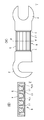
종래, 전자·전기 기기 등의 전기 회로의 안전 장치로서, 도 16의 (A), (B)에 나타낸 바와 같이, 소위 링크 퓨즈라고 칭해지는, 한 쌍의 손톱형 단자(91, 91) 사이를 땜납 등의 접속 매체(93)에 의해 선상 또는 띠상의 용단부(92)로 접속하여 이루어지는 전류 퓨즈(90)가 사용되고 있다. 또한, 도 16의 (A)는 종래의 전류 퓨즈의 일례를 나타내는 평면도이고, 도 16의 (B)는 도 16의 (A)의 A-A' 단면도이다.16A and 16B, a pair of nail-shaped terminals 91 and 91, called so-called link fuses, are provided between the pair of nail-shaped terminals 91 and 91 as safety devices for electronic circuits such as electronic and electric devices A current fuse 90 is used which is formed by connecting a
이러한 종류의 전류 퓨즈(90)는, 손톱형 단자(91)로서 일반적으로 구리 단자가 사용되고, 용단부(92)로서 일반적으로 납에 소량의 Sn, Ag 등을 가한 선상 또는 띠상의 녹기 쉬운 합금으로 이루어지는 용단 부재가 사용되고, 그의 전기 회로에 규정 용량 이상의 과전류가 흘렀을 때에 용단부(92)가 순시에 용단하여 기기의 안전성을 유지하도록 되어 있다.The current fuse 90 of this type is generally composed of a copper terminal as the nail-like terminal 91 and a
종래의 링크 퓨즈는, 납 합금 등을 용단 부재로서 사용한 용단부(92)의 양단에 손톱형 단자(91, 91)를 접속한 것, 혹은 아연 합금에 의해 용단부(92) 및 손톱형 단자(91, 91)를 일체 성형한 것이 제공되어 있다. 그러나, 납 합금은 환경 부하가 높은 유해 금속이고, 카드뮴, 수은 혹은 이들의 합금 등과 함께, 삭감이 강하게 요구되고 있다.The conventional link fuse is formed by connecting nail-shaped terminals 91 and 91 to both ends of a
납 대체 재료인 Sn 합금은 손톱형 단자(91)와의 접속에 있어서, 납땜 시에 Sn 합금이 용융되어 버리기 때문에, 용단 부재로서 채용하는 것은 곤란하다. 또한, 아연 합금은 융점이 약 400℃로 납 합금보다도 100℃ 가까이 높고, 비저항이 약 6μΩ·㎝로 납 합금의 약 21μΩ·㎝에 비해 1/3 이상 낮기 때문에, 용단 시의 손톱형 단자(91)의 온도가 고온이 되고, 링크 퓨즈가 접속된 회로 기판의 단자부 등의 주변 부재나 기기 본체 혹은 유저에게 열영향을 부여하는 리스크가 있다. 그 때문에, 용단부(92)를 국부적으로 가늘게 하는 등의 가공이 필요해지지만, 저항값이 높아지거나 높은 전류 정격에 대응하기 어려운 경향이 있다.The Sn alloy which is a substitute for lead is melted at the time of soldering at the time of connection with the nail-shaped terminals 91, so that it is difficult to adopt it as a melting end member. Since the zinc alloy has a melting point of about 400 캜 which is higher than that of the lead alloy by about 100 캜 and a specific resistance of about 6 · m and is at least 1/3 lower than about 21 · m of the lead alloy, Is high in temperature, and there is a risk that thermal influence is given to the peripheral members such as the terminal portion of the circuit board to which the link fuse is connected, the device body, or the user. For this reason, machining such as locally thinning of the
그래서, 본 발명은, 단자부에 대한 접속성을 개선함과 함께, 저항값의 상승을 초래하는 일 없이 전류 정격의 향상에 대응 가능하며, 또한 용단 시에 있어서의 단자부의 이상한 과열을 억제할 수 있는 전류 퓨즈를 제공하는 것을 목적으로 한다.SUMMARY OF THE INVENTION It is therefore an object of the present invention to improve the connecting property to the terminal portion and to cope with the improvement of the current rating without causing a rise in the resistance value and to suppress the abnormal overheating of the terminal portion at the time of melting And to provide a current fuse.
또한, 본 발명은, 상기에 더하여, 환경 규제의 강화에도 대응 가능한 납 프리의 전류 퓨즈를 제공하는 것을 목적으로 한다.It is still another object of the present invention to provide a lead-free current fuse capable of coping with the enhancement of environmental regulations.
상술한 과제를 해결하기 위해, 본 발명에 관한 전류 퓨즈는, 2개의 걸림 결합 단자부와, 상기 걸림 결합 단자부 사이에 형성된 용단부를 가지며, 상기 용단부는, 저융점 금속과 상기 저융점 금속보다도 융점이 높은 제1 고융점 금속을 적층한 가용 도체로 형성된 것이다.In order to solve the problems described above, the current fuse according to the present invention has two engagement terminal portions and a fusing portion formed between the engagement terminal portions, wherein the fusing portion has a melting point higher than that of the low- And the first high melting point metal.
또한, 본 발명에 관한 전류 퓨즈는, 상기 저융점 금속은 Sn 또는 Sn을 주성분으로 하는 합금이고, 상기 제1 고융점 금속은 Ag, Cu 또는 Ag 혹은 Cu를 주성분으로 하는 합금이다.Further, in the current fuse according to the present invention, the low melting point metal is an alloy containing Sn or Sn as a main component, and the first high melting point metal is an alloy containing Ag, Cu, Ag, or Cu as a main component.
본 발명에 따르면, 가용 도체는 저융점 금속과 제1 고융점 금속이 적층된 적층체인 점에서, 걸림 결합 단자부로의 솔더(solder) 접속 시 등에 있어서 저융점 금속이 용융된 경우에도, 제1 고융점 금속으로 피복됨으로써 용단하는 일이 없고, 솔더 접속이 가능하다.According to the present invention, since the usable conductor is a lamination layer in which a low-melting-point metal and a first high-melting-point metal are laminated, even when a low-melting-point metal is melted at the time of solder connection to the engaging terminal portion, It is not melted by being coated with the melting point metal, and solder connection is possible.
또한, 가용 도체는, 제1 고융점 금속보다도 융점이 낮은 저융점 금속이 적층되어 있기 때문에, 과전류에 의한 자기 발열에 의해, 저융점 금속의 융점에서부터 용융을 개시하고, 제1 고융점 금속을 침식하기 시작하여, 제1 고융점 금속이 자신의 융점보다도 낮은 온도에서 용융된다. 따라서, 본 발명에 따르면, 걸림 결합 단자부의 과열을 방지함과 함께, 저융점 금속에 의한 제1 고융점 금속의 용식 작용을 이용하여 빠르게 가용 도체가 용단되어 전류 경로를 차단할 수 있다.Since the usable conductor is a laminate of a low melting point metal having a melting point lower than that of the first high melting point metal, melting is started from the melting point of the low melting point metal by self heat generation due to the overcurrent, and the melting point of the first high melting point metal is eroded The first refractory metal is melted at a temperature lower than its melting point. Therefore, according to the present invention, it is possible to prevent overheating of the engaging terminal portion and to quickly blow the usable conductor by utilizing the solubility of the first refractory metal by the low melting point metal, thereby blocking the current path.
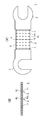
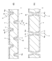
도 1의 (A)는 본 발명이 적용된 전류 퓨즈의 평면도이고, 도 1의 (B)는 도 1의 (A)의 A-A' 단면도이다.
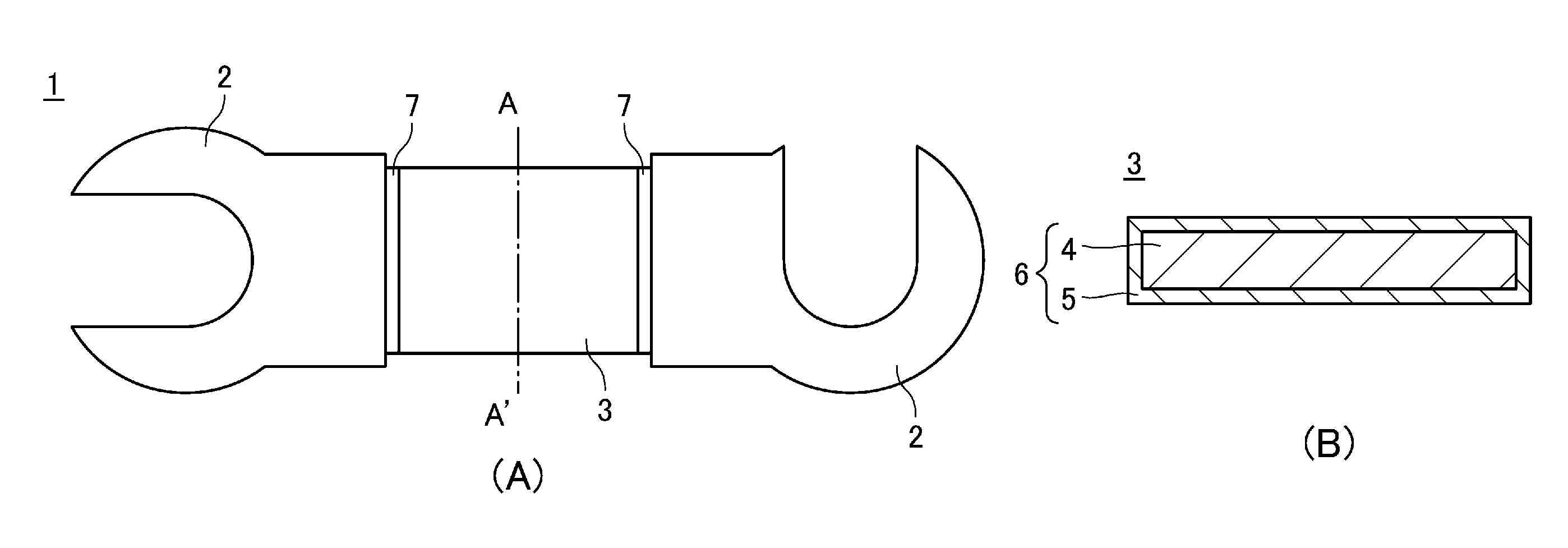
도 2의 (A)는 용단부에 변형 규제부가 형성된 전류 퓨즈의 평면도이고, 도 2의 (B)는 도 2의 (A)의 A-A' 단면도이다.
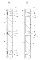
도 3의 (A)는 비관통 구멍을 형성한 가용 도체의 가열 전에 있어서의 단면도이고, 도 3의 (B)는 도 3의 (A)에 나타내는 가용 도체의 가열 후에 있어서의 단면도이다.
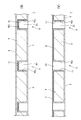
도 4의 (A)는 관통 구멍 내가 제2 고융점 금속에 의해 충전된 가용 도체를 나타내는 단면도이고, 도 4의 (B)는 비관통 구멍 내가 제2 고융점 금속에 의해 충전된 가용 도체를 나타내는 단면도이다.
도 5의 (A)는 단면이 직사각 형상인 관통 구멍을 형성한 가용 도체를 나타내는 단면도이고, 도 5의 (B)는 단면이 직사각 형상인 비관통 구멍을 형성한 가용 도체를 나타내는 단면도이다.
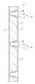
도 6은 구멍의 개구단측의 상측까지 제2 고융점 금속을 마련한 가용 도체를 나타내는 단면도이다.
도 7의 (A)는 비관통 구멍을 대향하여 형성한 가용 도체를 나타내는 단면도이고, 도 7의 (B)는 비관통 구멍을 대향시키지 않고 형성한 가용 도체를 나타내는 단면도이다.
도 8은 저융점 금속에 제1 고융점 입자를 배합한 가용 도체를 나타내는 단면도이다.
도 9의 (A)는 저융점 금속에 저융점 금속의 두께보다도 입자 직경이 작은 제1 고융점 입자를 배합한 가용 도체의 가열 전에 있어서의 단면도이고, 도 9의 (B)는 도 9의 (A)에 나타내는 가용 도체의 가열 후에 있어서의 단면도이다.
도 10은 저융점 금속에 제2 고융점 입자를 압입한 가용 도체를 나타내는 단면도이다.
도 11은 제1 고융점 금속 및 저융점 금속에 제2 고융점 입자를 압입한 가용 도체를 나타내는 단면도이다.
도 12는 제2 고융점 입자의 양단에 돌출 테두리부를 형성한 가용 도체를 나타내는 단면도이다.
도 13의 (A)는 용단부에 홈을 형성한 변형 규제부를 형성한 전류 퓨즈의 가열 전에 있어서의 평면도이고, 도 13의 (B)는 도 13의 (A)의 A-A' 단면도이다.
도 14의 (A)는 걸림 결합 단자부 및 용단부를 가용 도체로 형성한 전류 퓨즈를 나타내는 평면도이고, 도 14의 (B)는 도 14의 (A)의 A-A' 단면도이다.
도 15의 (A)는 걸림 결합 단자부 및 용단부를 변형 규제부가 형성된 가용 도체로 형성한 전류 퓨즈를 나타내는 평면도이고, 도 15의 (B)는 도 15의 (A)의 A-A' 단면도이다.
도 16의 (A)는 종래의 전류 퓨즈의 일례를 나타내는 평면도이고, 도 16의 (B)는 도 16의 (A)의 A-A' 단면도이다.FIG. 1 (A) is a plan view of a current fuse to which the present invention is applied, and FIG. 1 (B) is a cross-sectional view taken along line AA 'of FIG.
2 (A) is a plan view of a current fuse having a deformation restricting portion formed at a free end thereof, and FIG. 2 (B) is a sectional view taken along line AA 'of FIG.
Fig. 3 (A) is a cross-sectional view before heating of a usable conductor provided with a non-through hole, and Fig. 3 (B) is a cross-sectional view after heating of the usable conductor shown in Fig.
4A is a cross-sectional view showing a usable conductor filled with the second refractory metal through the through hole, and FIG. 4B is a cross-sectional view showing a usable conductor filled with the second refractory metal by the non- Sectional view.
FIG. 5A is a cross-sectional view showing a usable conductor having a through hole with a rectangular cross section, and FIG. 5B is a cross sectional view showing a usable conductor having a non-through hole having a cross section of a rectangular shape.
6 is a cross-sectional view showing a usable conductor provided with a second refractory metal up to the opening end side of the hole.
Fig. 7A is a cross-sectional view showing a usable conductor opposed to the non-through hole, and Fig. 7B is a cross-sectional view showing the usable conductor formed without opposing the non-through hole.
8 is a cross-sectional view showing a usable conductor in which a first melting point particle is blended with a low melting point metal.
9 (A) is a cross-sectional view of a low-melting-point metal before heating of a usable conductor containing a first high-melting-point particle having a particle diameter smaller than that of a low-melting-point metal, and FIG. 9 (B) Sectional view after heating of the usable conductor shown in Fig.
10 is a cross-sectional view showing a usable conductor in which the second high melting point particles are pressed into the low melting point metal.
11 is a cross-sectional view showing a usable conductor in which the second high melting point particles are pressed into the first high melting point metal and the low melting point metal.
Fig. 12 is a cross-sectional view showing a usable conductor in which protruding rims are formed at both ends of the second high melting point particles.
Fig. 13A is a plan view of a current fuse formed with a deformation restricting portion formed with a groove in a free end portion before heating, and Fig. 13B is a sectional view taken along the line AA 'in Fig.
Fig. 14A is a plan view showing a current fuse in which a latching terminal portion and a fusing end portion are formed of a usable conductor, and Fig. 14B is a sectional view taken along the line AA 'in Fig.
FIG. 15A is a plan view showing a current fuse in which a latching terminal portion and a free end portion are formed of a usable conductor provided with a deformation restricting portion, and FIG. 15B is a cross sectional view taken along the line AA 'in FIG.
FIG. 16A is a plan view showing an example of a conventional current fuse, and FIG. 16B is a sectional view taken along line AA 'of FIG. 16A.
이하, 본 발명이 적용된 전류 퓨즈에 대하여, 도면을 참조하면서 상세하게 설명한다. 또한, 본 발명은 이하의 실시 형태에만 한정되는 것은 아니고, 본 발명의 요지를 일탈하지 않는 범위 내에서 다양한 변경이 가능한 것은 물론이다. 또한, 도면은 모식적인 것이고, 각 치수의 비율 등은 현실의 것과는 상이한 경우가 있다. 구체적인 치수 등은 이하의 설명을 참작하여 판단해야 하는 것이다. 또한, 도면 상호간에 있어서도 서로의 치수의 관계나 비율이 상이한 부분이 포함되어 있는 것은 물론이다.Hereinafter, a current fuse to which the present invention is applied will be described in detail with reference to the drawings. It is needless to say that the present invention is not limited to the following embodiments, and various modifications can be made without departing from the gist of the present invention. In addition, the drawings are schematic, and the ratios of the dimensions and the like may be different from the actual ones. The specific dimensions and the like should be judged based on the following description. It is needless to say that the drawings also include portions having different dimensional relationships or ratios.
[전류 퓨즈][Current fuse]
도 1에 나타낸 바와 같이, 본 발명이 적용된 전류 퓨즈(1)는, 2개의 걸림 결합 단자부(2, 2)와, 걸림 결합 단자부(2, 2) 사이에 형성된 용단부(3)를 갖는다. 전류 퓨즈(1)는 2개의 걸림 결합 단자부(2, 2)가 전기 회로의 단자부 사이에 걸림 결합되어 나사 고정 등이 됨으로써, 당해 전기 회로의 전류 경로 위에 도입된다. 그리고, 전류 퓨즈(1)는 그 전기 회로에 규정 용량 이상의 과전류가 흘렀을 때에 용단부(3)가 순시에 용단되어 한 쌍의 걸림 결합 단자부(2, 2) 사이의 전류 경로를 차단하여, 기기의 안전성을 유지하는 것이다.1, the
[걸림 결합 단자부][Engaging terminal portion]
걸림 결합 단자부(2)는 일부가 개방된 손톱 형상이나 중앙이 개구된 대략 원반 형상 등, 도시하지 않은 전기 회로의 단자부에 대하여 걸림 결합 가능한 공지의 형상을 갖고, 예를 들어 볼트나 비스 등에 의해 착탈 가능하게 접합된다. 걸림 결합 단자부(2)의 재질로서는 적당한 강성을 갖고, 또한 양호한 도전성이면 특별히 한정되는 것은 아니며, 구리, 구리-니켈 합금 등이 적합하게 사용된다.The
전류 퓨즈(1)는 한 쌍의 걸림 결합 단자부(2, 2) 사이에 솔더 등의 접속재(7)에 의해 용단부(3)가 접속되고, 용단부(3)를 통해 도통되어 있다. 또한, 접속재(7)는 솔더에 한정되지 않고, 걸림 결합 단자부(2)와 용단부(3)를 도통 접속 가능한 어떤 재료든 사용할 수 있다.The
[용단부][Fusing section]
용단부(3)는, 규정 용량 이상의 과전류가 흘렀을 때에 용단하여, 한 쌍의 걸림 결합 단자부(2, 2) 사이에 걸치는 전류 경로를 차단하는 것이다. 용단부(3)는 저융점 금속(4)과 저융점 금속(4)보다도 융점이 높은 제1 고융점 금속(5)을 적층한 가용 도체(6)로 형성되어 있다.The fusing
제1 고융점 금속(5)은, 예를 들어 Ag, Cu 또는 Ag 혹은 Cu를 주성분으로 하는 합금이 적합하게 사용되고, 걸림 결합 단자부(2)로의 접속 시나 전류 퓨즈(1)를 회로 기판의 단자부에 솔더 실장을 행하는 경우에 있어서의 가열 온도에서도 용융되지 않는 높은 융점을 갖는다. 또한, 제1 고융점 금속(5)은 납을 함유시키는 경우에도 함유율을 RoHS 지령의 1000ppm 이하로 하는 것이 바람직하다.As the first
저융점 금속(4)은, 과전류에 의해 온도가 상승하여 소정의 온도에 도달했을 때에 용단되는 온도를 융점으로 하는 금속이면, 특별히 한정되는 것은 아니며, 예를 들어 Sn 또는 Sn을 주성분으로 하는 합금으로 「Pb 프리 솔더」라고 일반적으로 불리는 재료가 적합하게 사용된다. 저융점 금속(4)의 융점은, 반드시 솔더 접속의 온도보다도 높을 필요는 없고, 200℃ 정도에서 용융되어도 된다. 또한, 저융점 금속(4)은, 더 낮은 120℃ 내지 140℃ 정도에서 용융되는 Bi, In 또는 Bi 혹은 In을 포함하는 합금을 사용해도 된다. 저융점 금속(4)은 이들 금속 중 선택하거나 혹은 그것들을 소정의 비율로 합금화함으로써 원하는 융점 온도를 자유롭게 설정할 수 있다. 또한, 저융점 금속(4)은 납을 함유시키는 경우에도 함유율을 RoHS 지령의 1000ppm 이하로 하는 것이 바람직하다.The low
가용 도체(6)는, 적어도 저융점 금속(4)의 표리 양면에 제1 고융점 금속(5)을 적층한 적층체이고, 바람직하게는 저융점 금속(4)이 내층을 구성하고, 제1 고융점 금속(5)이 외층을 구성하는 적층 구조를 갖는다. 따라서, 가용 도체(6)는 걸림 결합 단자부(2)로의 솔더 접속 시 등에 있어서 저융점 금속(4)이 용융된 경우에도, 제1 고융점 금속(5)으로 피복됨으로써 용단되는 경우가 없고, 솔더 접속이 가능해 종래와 동일한 공정으로 제조할 수 있다.The
또한, 가용 도체(6)는 제1 고융점 금속(5)보다도 융점이 낮은 저융점 금속(4)이 적층되어 있기 때문에, 과전류에 의한 자기 발열에 의해, 저융점 금속(4)의 융점에서부터 용융을 개시하여, 제1 고융점 금속(5)을 침식하기 시작한다. 예를 들어, 저융점 금속(4)을 Sn-Bi계 합금이나 In-Sn계 합금 등으로 구성한 경우, 가용 도체(6)는 140℃나 120℃ 전후라고 하는 저온도에서부터 용융을 개시한다. 그리고, 전류 퓨즈(1)는 저융점 금속(4)에 의한 제1 고융점 금속(5)의 침식 작용(솔더 흡입)을 이용함으로써, 제1 고융점 금속(5)이 자신의 융점보다도 낮은 온도에서 용융된다. 따라서, 가용 도체(6)는 걸림 결합 단자부(2)의 과열을 방지함과 함께, 저융점 금속(4)에 의한 제1 고융점 금속(5)의 용식 작용을 이용하여 빠르게 용단되어 전류 경로를 차단할 수 있다.Since the
또한, 가용 도체(6)는 고융점 금속 피복되어 있음으로써 용단 온도를 종래의 Cu 등의 고융점 금속으로 이루어지는 전류 퓨즈보다도 대폭으로 저감시킬 수 있는 점에서, 용단부를 국소적으로 가늘게 하는 등의 가공도 불필요하고, 정격을 높여 대전류에 대응 가능해진다. 또한, 종래의 납계 고융점 솔더를 사용한 가용 도체에 비해, 도체 저항을 대폭으로 저감시킬 수 있어, 동일 사이즈의 종래의 전류 퓨즈 등에 비해, 전류 정격을 대폭으로 향상시킬 수 있다. 또한, 동일한 전류 정격을 갖는 종래의 전류 퓨즈보다도 소형화, 박형화를 도모할 수 있다.In addition, since the
또한, 가용 도체(6)는 전류 퓨즈(1)가 도입된 전기 계통에 비정상적으로 높은 전압이 순간적으로 인가되는 서지에 대한 내성(내펄스성)을 향상시킬 수 있다. 즉, 가용 도체(6)는, 예를 들어 100A의 전류가 수msec 흐른 경우까지 용단해서는 안된다. 이 점에서, 매우 단시간에 흐르는 대전류는 도체의 표층을 흐르는 점에서(표피 효과), 가용 도체(6)는 외층으로서 저항값이 낮은 Ag 도금 등의 제1 고융점 금속(5)이 마련되어 있기 때문에, 서지에 의해 인가된 전류를 흘리기 쉽고, 자기 발열에 의한 용단을 방지할 수 있다. 따라서, 가용 도체(6)는 종래의 솔더 합금으로 이루어지는 퓨즈에 비해, 서지에 대한 내성을 향상시킬 수 있다.Further, the
또한, 환경 오염을 고려한 경우, 가용 도체(6)에 사용되는 재료로서는, 납이나 카드뮴, 수은 혹은 이들의 합금 등의 유해 금속은 최대한 사용을 삼가한 것이 바람직하다. 현재 링크 퓨즈에 있어서 가용 도체는 전기용품 안전법으로 정해진 재료(납, 주석, 아연 또는 이들을 주성분으로 하는 합금)로 되어 있다. 상술한 바와 같이, 주석계 재료는 용융 온도가 낮아 구리 단자와의 솔더 접속성에 난점이 있고, 아연계는 비교적 고융점이기 때문에 용단 시의 열영향의 과제가 있다. 또한, 납계는 그것들의 과제는 해결하기 쉽고, 또한 현재는 환경 규제(개정 RoHS 지령) 대상 제외로 되어 있지만, 장래는 사회적 요청으로 인해 삭감 대상이 될 수 있는 재료이다.In consideration of environmental pollution, harmful metals such as lead, cadmium, mercury or their alloys are preferably used as a material for the
이 점에서, 본 발명이 적용된 전류 퓨즈(1)에 의하면, 납계의 유해 금속을 사용하지 않고 가용 도체(6)를 형성함으로써, 환경 규제의 강화에도 대응 가능해진다. 또한, 상술한 바와 같이, 가용 도체(6)를, 저융점 금속(4)이 내층을 구성하고, 제1 고융점 금속(5)이 외층을 구성하는 적층 구조로 함으로써, 구리의 걸림 결합 단자부(2)와의 솔더 접속에 있어서도 형상을 유지할 수 있고, 또한 용단 시에 있어서도, 낮은 온도에서 용융되어, 걸림 결합 단자부(2)의 과열을 방지함과 함께, 빠르게 용단하여 전류 경로를 차단할 수 있다.In this respect, according to the
가용 도체(6)는 저융점 금속(4)의 표면에 제1 고융점 금속(5)을 전해 도금법 등의 성막 기술을 사용함으로써 제조할 수 있다. 예를 들어, 가용 도체(6)는 소정의 형상으로 성형된 솔더 박의 표면에 Ag 도금을 실시함으로써 효율적으로 제조할 수 있다. 그리고, 솔더 등의 접속재(7)에 의해 걸림 결합 단자부(2)에 접속된다.The
또한, 가용 도체(6)는 걸림 결합 단자부(2)와 용접에 의해 접속해도 된다. 이것에 의해서도, 한 쌍의 걸림 결합 단자부(2, 2)가 가용 도체(6)를 통해 전기적으로 접속된다.In addition, the
또한, 가용 도체(6)는 저융점 금속(4)의 체적을, 제1 고융점 금속(5)의 체적보다도 크게 형성하는 것이 바람직하다. 가용 도체(6)는 자기 발열에 의해 저융점 금속(4)이 용융됨으로써 제1 고융점 금속(5)을 용식하고, 이에 의해 빠르게 용융, 용단할 수 있다. 따라서, 가용 도체(6)는 저융점 금속(4)의 체적을 제1 고융점 금속(5)의 체적보다도 크게 형성함으로써, 이 용식 작용을 촉진하여, 빠르게 한 쌍의 걸림 결합 단자부(2, 2) 사이를 차단할 수 있다.It is preferable that the volume of the low
[변형 규제부][Regulation of Deformation]
또한, 가용 도체(6)는 솔더 접속 시 등에 용융된 저융점 금속(4)의 유동을 억제하여, 변형을 규제하는 변형 규제부(9)를 형성해도 된다.The
변형 규제부(9)는, 도 2에 나타낸 바와 같이 저융점 금속(4)에 형성된 1개 또는 복수의 구멍(10)의 측면(10a)의 적어도 일부가, 제1 고융점 금속(5)과 연속하는 제2 고융점 금속(11)에 의해 피복되어 이루어진다. 구멍(10)은, 예를 들어 저융점 금속(4)에 바늘 등의 첨예체를 찌르거나, 혹은 저융점 금속(4)에 금형을 사용하여 프레스 가공을 실시하는 것 등에 의해 형성할 수 있다. 또한, 구멍(10)은 소정의 패턴, 예를 들어 사방 격자상 혹은 육방 격자상으로 저융점 금속(4)의 전체면에 걸쳐서 균일하게 형성되어 있다.The
제2 고융점 금속(11)을 구성하는 재료는, 제1 고융점 금속(5)을 구성하는 재료와 마찬가지로, 솔더 접속 온도에 의해서는 용융되지 않는 높은 융점을 갖는다. 또한, 제2 고융점 금속(11)은 제1 고융점 금속(5)과 동일한 재료이며, 제1 고융점 금속(5)의 형성 공정에서 동시에 형성되는 것이 제조 효율상, 바람직하다.Like the material constituting the first
이와 같은 가용 도체(6)는, 도 2에 나타낸 바와 같이 한 쌍의 걸림 결합 단자부(2, 2) 사이에, 솔더 등의 접속재(7)를 통해, 혹은 용접에 의해 접속된다. 이때, 가용 도체(6)는 저융점 금속(4)에 외층으로서 접속 온도에서도 용융되지 않는 제1 고융점 금속(5)을 적층함과 함께 변형 규제부(9)를 형성함으로써, 고온 환경 하에 노출된 경우에도, 가용 도체(6)의 변형을 용단 특성의 변동을 억제하는 일정한 범위 내로 억제할 수 있다. 따라서, 가용 도체(6)는 대면적화된 경우에도 용단 특성의 변동을 억제할 수 있어, 용이하게 전류 퓨즈(1)의 정격을 향상시킬 수 있다.As shown in Fig. 2, such a
즉, 가용 도체(6)는 저융점 금속(4)에 구멍(10)을 개구함과 함께, 구멍(10)의 측면(10a)을 제2 고융점 금속(11)으로 피복한 변형 규제부(9)를 구비함으로써, 솔더 접속 등의 외부 열원에 의해 저융점 금속(4)의 융점 이상의 고열 환경에 단시간 노출된 경우에도, 구멍(10)의 측면(10a)을 피복하는 제2 고융점 금속(11)에 의해, 용융된 저융점 금속(4)의 유동이 억제됨과 함께 외층을 구성하는 제1 고융점 금속(5)이 지지된다. 따라서, 가용 도체(6)는, 장력에 의해 용융된 저융점 금속(4)이 응집하여 팽창하거나, 혹은 용융된 저융점 금속(4)이 유출되어 얇아져, 국소적으로 찌그러짐이나 팽창이 발생하는 것을 억제할 수 있다.That is, the
이에 의해, 가용 도체(6)는 솔더 접속 시 등의 온도에서 국소적으로 찌그러짐이나 팽창 등의 변형에 따른 저항값의 변동을 방지하여, 소정의 온도나 전류로 소정의 시간에 용단되는 용단 특성을 유지할 수 있다. 또한, 가용 도체(6)는 전류 퓨즈(1)가 탑재된 회로 기판 위에 다른 표면 실장 부품이 리플로우 실장되거나, 혹은 회로 기판이 또 다른 회로 기판 위에 리플로우 실장되는 등, 리플로우 온도 하에 반복해서 노출된 경우에도, 변형 규제부(9)에 의해 변형이 억제되어, 용단 특성을 안정화할 수 있음과 함께, 실장 효율을 향상시킬 수 있다.As a result, the
또한, 후술하는 바와 같이, 가용 도체(6)가 대형 엘리먼트 시트로부터 잘라내어져 제조되는 경우에는, 가용 도체(6)의 측면으로부터 저융점 금속(4)이 노출됨과 함께, 당해 측면이 걸림 결합 단자부(2)와 솔더 등의 접속재(7)를 통해 접촉되어 있다. 이 경우도, 가용 도체(6)는 변형 규제부(9)에 의해 용융된 저융점 금속(4)의 유동을 억제하고 있기 때문에, 당해 측면으로부터 용융된 솔더 등의 접속재(7)를 흡입함으로써 저융점 금속(4)의 체적이 증가하여 국부적으로 저항값이 내려가는 경우도 없다.As described later, when the
또한, 가용 도체(6)는, 변형 규제부(9)를 구비함으로써, 과전류에 의한 줄 열 발열 당초에 있어서의 저융점 금속(4)의 용융 단계에서의 소정 외의 변형을 억제할 수 있다. 따라서, 가용 도체(6)는 변형 규제부(9)에 의해 발열 중에 있어서의 변형이 억제되어, 용단 특성을 안정화시킬 수 있다.The
[관통 구멍·비관통 구멍][Through holes and non-through holes]
여기서, 구멍(10)은, 도 2의 (B)에 나타낸 바와 같이 저융점 금속(4)을 두께 방향으로 관통하는 관통 구멍으로서 형성해도 되거나, 혹은 도 3의 (A), (B)에 나타낸 바와 같이 비관통 구멍으로서 형성해도 된다. 구멍(10)을 관통 구멍으로서 형성한 경우, 구멍(10)의 측면(10a)을 피복하는 제2 고융점 금속(11)은 저융점 금속(4)의 표리면에 적층된 제1 고융점 금속(5)과 연속된다. 또한, 구멍(10)의 형상은 특별히 한정은 없고, 원형 외에, 타원형, 모서리 둥근 직사각형 또는 사각형이어도 된다.Here, the
또한, 구멍(10)을 비관통 구멍으로서 형성한 경우, 도 3의 (A)에 나타낸 바와 같이 구멍(10)은 저면(10b)까지 제2 고융점 금속(11)에 의해 피복되어 있는 것이 바람직하다. 가용 도체(6)는 구멍(10)을 비관통 구멍으로서 형성하고, 가열에 의해 저융점 금속(4)이 유동한 경우라도, 구멍(10)의 측면(10a)을 피복하는 제2 고융점 금속(11)에 의해 유동이 억제됨과 함께 외층을 구성하는 제1 고융점 금속(5)이 지지되기 때문에, 도 3의 (B)에 나타낸 바와 같이, 가용 도체(6)의 두께의 변동은 경미하여, 용단 특성이 변동되지는 않는다.When the
[고융점 금속의 충전][Filling of high melting point metal]
또한, 구멍(10)은, 도 4의 (A), (B)에 나타낸 바와 같이 제2 고융점 금속(11)에 의해 충전되어 있어도 된다. 구멍(10)이 제2 고융점 금속(11)에 의해 충전됨으로써, 가용 도체(6)는 외층을 구성하는 제1 고융점 금속(5)을 지지하는 변형 규제부(9)의 강도를 향상시켜 가용 도체(6)의 변형을 더 억제할 수 있음과 함께, 저저항화에 의해 정격을 향상시킬 수 있다.The
후술하는 바와 같이, 제2 고융점 금속(11)은, 예를 들어 구멍(10)이 개구된 저융점 금속(4)에 제1 고융점 금속(5)을 전해 도금하는 것 등에 의해 형성할 때에, 동시에 형성할 수 있고, 구멍 직경이나 도금 조건을 조정함으로써 구멍(10) 내를 제2 고융점 금속(11)으로 메울 수 있다.As described later, the second
[단면 형상][Cross-sectional shape]
또한, 구멍(10)은, 도 2의 (B)나 도 3, 도 4에 나타낸 바와 같이 단면 테이퍼상으로 형성해도 된다. 구멍(10)은, 예를 들어 저융점 금속(4)에 바늘 등의 첨예체를 찔러 개구시킴으로써, 당해 첨예체의 형상에 따라 단면 테이퍼상으로 형성할 수 있다. 또한, 구멍(10)은, 도 5의 (A), (B)에 나타낸 바와 같이 단면 직사각 형상으로 형성해도 된다. 가용 도체(6)는, 예를 들어 저융점 금속(4)에 단면 직사각 형상의 구멍(10)에 따른 금형을 사용하여 프레스 가공을 행하는 것 등에 의해 단면 직사각 형상의 구멍(10)을 개구할 수 있다.The
[고융점 금속의 일부 피복][Some coating of high melting point metal]
또한, 변형 규제부(9)는 구멍(10)의 측면(10a)의 적어도 일부가 제1 고융점 금속(5)과 연속하는 제2 고융점 금속(11)에 의해 피복되어 있으면 되고, 도 6에 나타낸 바와 같이, 측면(10a)의 상측까지 제2 고융점 금속(11)에 의해 피복되어 있어도 된다. 또한, 변형 규제부(9)는 저융점 금속(4)과 제1 고융점 금속(5)의 적층체를 형성한 후, 제1 고융점 금속(5)의 위에서 첨예체를 찌름으로써 구멍(10)을 개구 혹은 관통함과 함께, 제1 고융점 금속(5)의 일부를 구멍(10)의 측면(10a)에 압입함으로써 제2 고융점 금속(11)으로 해도 된다.The
도 6에 나타낸 바와 같이, 구멍(10)의 측면(10a)의 개구단측의 일부에 제1 고융점 금속(5)과 연속하는 제2 고융점 금속(11)을 적층함으로써도, 구멍(10)의 측면(10a)에 적층된 제2 고융점 금속(11)에 의해 용융된 저융점 금속(4)의 유동을 억제함과 함께, 개구단측의 제1 고융점 금속(5)을 지지하고, 가용 도체(6)의 국소적인 찌그러짐이나 팽창의 발생을 억제할 수 있다.6, even when the second
또한, 도 7의 (A)에 나타낸 바와 같이, 변형 규제부(9)는 구멍(10)을 비관통 구멍으로서 형성함과 함께, 저융점 금속(4)의 한쪽 면 및 다른 쪽 면에 서로 대향시켜 형성해도 된다. 또한, 도 7의 (B)에 나타낸 바와 같이, 변형 규제부는 구멍(10)을 비관통 구멍으로서 형성함과 함께, 저융점 금속(4)의 한쪽 면 및 다른 쪽 면에 서로 대향시키지 않고 형성해도 된다. 비관통의 구멍(10)을 저융점 금속(4)의 양면에 서로 대향 또는 비대향으로 형성함으로써도, 각 구멍(10)의 측면(10a)을 피복하는 제2 고융점 금속(11)에 의해 용융된 저융점 금속(4)의 유동이 규제됨과 함께, 외층을 구성하는 제1 고융점 금속(5)이 지지된다. 따라서, 가용 도체(6)는 장력에 의해 용융된 저융점 금속(4)이 응집하여 팽창하거나, 혹은 용융된 저융점 금속(4)이 유출되어 얇아져, 국소적으로 찌그러짐이나 팽창이 발생하는 것을 억제할 수 있다.7 (A), the
또한, 변형 규제부(9)는, 구멍(10)의 측면(10a)에 전해 도금에 의해 제2 고융점 금속(11)을 피복하기 위해 도금액이 유입 가능한 구멍 직경을 구비하고 있는 것이 제조 효율상 바람직하며, 예를 들어 구멍의 최소 직경이 50㎛ 이상이 되고, 보다 바람직하게는 70 내지 80㎛가 되어 있다. 또한, 구멍(10)의 최대 직경은 제2 고융점 금속(11)의 도금 한계나 가용 도체(6)의 두께 등과의 관계에서, 적절히 설정할 수 있지만, 구멍 직경이 크면 초기 저항값이 높아지는 경향이 있다.The
또한, 변형 규제부(9)는 구멍(10)의 깊이를 저융점 금속(4)의 두께의 50% 이상으로 하는 것이 바람직하다. 구멍(10)의 깊이가 이것보다도 얕으면, 용융된 저융점 금속(4)의 유동을 억제할 수 없어, 가용 도체(6)의 변형에 따라 용단 특성의 변동을 초래할 우려가 있다.It is preferable that the
또한, 변형 규제부(9)는, 저융점 금속(4)에 형성되는 구멍(10)을 소정의 밀도, 예를 들어 15×15㎜당 1개 이상의 밀도로 형성되어 있는 것이 바람직하다.It is preferable that the
또한, 변형 규제부(9)는, 구멍(10)을, 과전류 시에 가용 도체(6)가 용단되는 부위에 형성시키는 것이 바람직하다. 가용 도체(6)의 용단 부위는, 전류 퓨즈(1)의 한 쌍의 걸림 결합 단자부(2, 2)에 의해 지지되어 있지 않아, 상대적으로 강성이 낮은 부위이기 때문에, 당해 부위에서 저융점 금속(4)의 유동에 의한 변형이 발생하기 쉽다. 그로 인해, 가용 도체(6)의 용단 부위에 구멍(10)을 개구함과 함께 측면(10a)을 제2 고융점 금속(11)에 의해 피복함으로써, 용단 부위에서의 저융점 금속(4)의 유동을 억제하여 변형을 방지할 수 있다.It is preferable that the
또한, 변형 규제부(9)는 구멍(10)을 적어도 가용 도체(6)의 중앙부에 형성하는 것이 바람직하다. 가용 도체(6)는 양단부가 한 쌍의 걸림 결합 단자부(2, 2)에 지지되고, 외주로부터 가장 먼 거리에 있는 중앙부는 가장 강성이 낮아 변형이 발생하기 쉽다. 그로 인해, 가용 도체(6)는 당해 중앙부에, 측면(10a)이 제2 고융점 금속(11)에 의해 피복된 구멍(10)을 형성함으로써, 당해 중앙부의 강성을 높여, 변형을 효과적으로 방지할 수 있다. It is preferable that the
또한, 변형 규제부(9)는 가용 도체(6)의 중심을 지나는 선의 양측에서의 구멍(10)의 수량차 혹은 밀도차를 50% 이하로 해도 된다. 즉, 변형 규제부(9)는 복수의 구멍(10)을 가용 도체(6)에 분산 배치시킴과 함께, 가용 도체(6)의 전체면에 걸쳐서 대략 균등하게 변형 규제부(9)의 효과를 작용시키기 위해, 가용 도체(6)의 중심을 지나는 선의 양측에서의 수량차 또는 밀도차를 50% 이내로 한다. 예를 들어, 3점 지지로 균형을 잡도록 3개의 구멍(10)을 가용 도체(6)의 전체면에 균등 배치한 경우, 가용 도체(6)의 중심을 지나는 선의 양측에서의 구멍(10)의 수량차 혹은 밀도차는 50%가 된다. 퓨즈 요소의 중심을 지나는 선의 양측 구멍(10)의 수량차 혹은 밀도차를 50% 이하로 함으로써도, 가용 도체(6) 전체의 강성을 높여, 변형을 효과적으로 방지할 수 있다.The
[가용 도체의 제조 방법][Manufacturing method of usable conductor]
가용 도체(6)는 저융점 금속(4)에 변형 규제부(9)를 구성하는 구멍(10)을 개구한 후, 저융점 금속(4)에 고융점 금속을 도금 기술을 사용하여 성막함으로써 제조할 수 있다. 가용 도체(6)는, 예를 들어 긴 형상의 솔더 박에 소정의 구멍(10)을 개구한 후, 표면에 Ag 도금을 실시함으로써 엘리먼트 리본을 제조하고, 사용 시에는, 사이즈에 따라 절단함으로써, 효율적으로 제조할 수 있고, 또한 용이하게 사용할 수 있다.The
여기서, 종래의 저융점 금속과 고융점 금속의 적층 구조만으로 이루어지는 가용 도체에서는, 절단면으로부터의 솔더 등의 접속재(7)의 유입이나 저융점 금속(4)의 유출이 우려되는 점에서, 절단면과 접속재(7)의 접촉을 피하기 위해 양단부를 굴곡시키는 등의 가공을 검토할 필요도 있어, 제조 공정수의 증가나, 전류 퓨즈(1)의 소형화를 저해하는 등의 문제가 발생한다.Here, in the conventional usable conductor having only a laminated structure of the low-melting-point metal and the high-melting-point metal, in view of the possibility of the inflow of the connecting
이 점에서, 가용 도체(6)는 절단면으로부터 저융점 금속(4)이 노출되어 있어도, 변형 규제부(9)에 의해 용융된 저융점 금속(4)의 유동이 억제되어 있기 때문에, 절단면으로부터의 접속재(7)의 유입이나 저융점 금속(4)의 유출을 억제할 수 있어, 두께의 변동에 따른 저항값의 변동 및 용단 특성의 변동을 방지할 수 있다. 따라서, 절단면이 노출되는 양단부의 굴곡 등의 가공도 불필요하여, 제조 효율의 향상이나 전류 퓨즈(1)의 소형화를 도모할 수 있다.Since the flow of the low
그 밖에, 가용 도체(6)는 증착 등의 박막 형성 기술이나, 다른 주지의 적층 기술을 사용함으로써도, 저융점 금속(4)과 제1 고융점 금속(5)이 적층된 가용 도체(6)를 형성할 수 있다.In addition, the
또한, 가용 도체(6)는 외층을 구성하는 제1 고융점 금속(5)의 표면에 도시하지 않은 산화 방지막을 형성해도 된다. 가용 도체(6)는 외층의 제1 고융점 금속(5)이 추가로 산화 방지막에 의해 피복됨으로써, 예를 들어 제1 고융점 금속(5)으로서 Cu 도금층을 형성한 경우에도, Cu의 산화를 방지할 수 있다. 따라서, 가용 도체(6)는 Cu의 산화에 의해 용단 시간이 길어지는 사태를 방지할 수 있어, 단시간에 용단할 수 있다.In addition, the
또한, 가용 도체(6)는, 제1 고융점 금속(5)으로서 Cu 등의 저렴하지만 산화되기 쉬운 금속을 사용할 수 있어, Ag 등의 고가의 재료를 사용하지 않고 형성할 수 있다.In addition, the
제1 고융점 금속(5)의 산화 방지막은 저융점 금속(4)과 동일한 재료를 사용할 수 있으며, 예를 들어 Sn을 주성분으로 하는 Pb 프리 솔더를 사용할 수 있다. 또한, 산화 방지막은 제1 고융점 금속(5)의 표면에 주석 도금을 실시함으로써 형성할 수 있다. 그 밖에, 산화 방지막은 Au 도금이나 프리플럭스에 의해 형성할 수도 있다.The oxidation preventive film of the first
[엘리먼트 시트][Element Sheet]
또한, 가용 도체(6)는 대형 엘리먼트 시트로부터, 원하는 사이즈로 잘라내도 된다. 즉, 전체면에 걸쳐서 균일하게 변형 규제부(9)가 형성된 저융점 금속(4)과 제1 고융점 금속(5)의 적층체로 이루어지는 대형 엘리먼트 시트를 형성하고, 임의의 사이즈의 가용 도체(6)를 복수 잘라냄으로써 형성해도 된다. 엘리먼트 시트로부터 잘라내진 가용 도체(6)는 변형 규제부(9)가 전체면에 걸쳐서 균일하게 형성되어 있기 때문에, 절단면으로부터 저융점 금속(4)이 노출되어 있어도, 변형 규제부(9)에 의해 용융된 저융점 금속(4)의 유동이 억제되어 있기 때문에, 절단면으로부터의 솔더 등의 접속재(7)의 유입이나 저융점 금속(4)의 유출을 억제할 수 있어, 두께의 변동에 따른 저항값의 변동 및 용단 특성의 변동을 방지할 수 있다.In addition, the
또한, 상술한 긴 형상의 솔더 박에 소정의 구멍(10)을 개구한 후, 표면에 전해 도금을 실시함으로써 엘리먼트 리본을 제조하고, 이것을 소정의 길이로 절단하는 제법에서는, 가용 도체(6)의 사이즈가 엘리먼트 리본의 폭으로 규정되어 버려, 사이즈마다 엘리먼트 리본을 제조할 필요가 있었다.In addition, in the method of manufacturing the element ribbon by forming the
그러나, 대형 엘리먼트 시트를 형성함으로써, 가용 도체(6)를 원하는 사이즈로 잘라낼 수 있어, 사이즈의 자유도가 높아진다.However, by forming the large element sheet, the
또한, 긴 형상의 솔더 박에 전해 도금을 실시하면, 전계가 집중하는 길이 방향으로 걸치는 측연부에 제1 고융점 금속(5)이 두껍게 도금되어, 균일한 두께의 가용 도체(6)를 얻는 것이 곤란했다. 그로 인해, 전류 퓨즈(1)에 있어서, 가용 도체(6)의 당해 두꺼운 부위의 배치에 의해 용단 특성이 바뀌는 점에서 배치상의 제약도 생기고 있다.When electrolytic plating is performed on the elongated solder foil, the first
그러나, 대형 엘리먼트 시트를 형성함으로써, 가용 도체(6)를, 당해 두꺼운 부위를 피해 잘라낼 수 있어, 전체면에 걸쳐서 균일한 두께의 가용 도체(6)를 얻을 수 있다. 따라서, 엘리먼트 시트로부터 잘라내진 가용 도체(6)는 배치에 따라 용단 특성이 바뀌는 일도 없고, 배치의 자유도가 높아, 용단 특성의 안정화를 도모할 수 있다.However, by forming the large element sheet, the
[고융점 입자][High melting point particles]
또한, 가용 도체(6)는, 도 8에 나타낸 바와 같이 변형 규제부(9)를, 저융점 금속(4)보다도 융점이 높은 제1 고융점 입자(13)를 저융점 금속(4)에 배합함으로써 형성해도 된다. 제1 고융점 입자(13)는 땜납 접합 온도에서도 용융되지 않는 높은 융점을 갖는 물질이 사용되고, 예를 들어 Cu, Ag, Ni 등의 금속이나 이들을 포함하는 합금으로 이루어지는 입자, 유리 입자, 세라믹 입자 등을 사용할 수 있다. 또한, 제1 고융점 입자(13)는 구상, 인편상 등, 그 형상은 상관없다. 또한, 제1 고융점 입자(13)는, 금속이나 합금 등을 사용한 경우, 유리나 세라믹에 비해 비중이 큰 점에서 친화성이 양호하고 분산성이 우수하다.8, the
변형 규제부(9)는, 저융점 금속 재료에 제1 고융점 입자(13)를 배합한 후, 리본상으로 성형하는 것 등에 의해 제1 고융점 입자(13)가 단층으로 분산 배치된 저융점 금속(4)을 형성하고, 그 후, 제1 고융점 금속(5)이 적층됨으로써 형성된다. 또한, 변형 규제부(9)는 제1 고융점 금속(5)의 적층 후에 가용 도체(6)를 두께 방향으로 프레스함으로써, 제1 고융점 입자(13)를 제1 고융점 금속(5)에 밀착시켜도 된다. 이에 의해, 변형 규제부(9)는 제1 고융점 금속(5)이 제1 고융점 입자(13)에 의해 지지되고, 가열에 의해 저융점 금속(4)이 용융된 경우에도, 제1 고융점 입자(13)에 의해 저융점 금속(4)의 유동을 억제함과 함께 제1 고융점 금속(5)을 지지하고, 가용 도체(6)의 국부적인 찌그러짐이나 팽창의 발생을 억제할 수 있다.The
또한, 변형 규제부(9)는, 도 9의 (A)에 나타낸 바와 같이 저융점 금속(4)의 두께보다도 작은 입자 직경의 제1 고융점 입자(13)를 저융점 금속(4)에 배합해도 된다. 이 경우도, 도 9의 (B)에 나타낸 바와 같이, 변형 규제부(9)는 제1 고융점 입자(13)에 의해 용융된 저융점 금속(4)의 유동을 억제함과 함께, 제1 고융점 금속(5)을 지지하고, 가용 도체(6)의 국부적인 찌그러짐이나 팽창의 발생을 억제할 수 있다.9 (A), the
또한, 가용 도체(6)는, 도 10에 나타낸 바와 같이 변형 규제부(9)를, 저융점 금속(4)보다도 융점이 높은 제2 고융점 입자(15)를, 저융점 금속(4)에 압입시킴으로써 형성해도 된다. 제2 고융점 입자(15)는 상술한 제1 고융점 입자(13)와 동일한 물질을 사용할 수 있다.10, the
변형 규제부(9)는 저융점 금속(4)에 제2 고융점 입자(15)를 압입함으로써 매립되고, 그 후, 제1 고융점 금속(5)을 적층함으로써 형성된다. 이때, 제2 고융점 입자(15)는 저융점 금속(4)을 두께 방향으로 관통하는 것이 바람직하다. 이에 의해, 변형 규제부(9)는 제1 고융점 금속(5)이 제2 고융점 입자(15)에 의해 지지되고, 가열에 의해 저융점 금속(4)이 용융된 경우에도, 제2 고융점 입자(15)에 의해 저융점 금속(4)의 유동을 억제함과 함께 제1 고융점 금속(5)을 지지하고, 가용 도체(6)의 국부적인 찌그러짐이나 팽창의 발생을 억제할 수 있다.The
또한, 가용 도체(6)는, 도 11에 나타낸 바와 같이 변형 규제부(9)를, 저융점 금속(4)보다도 융점이 높은 제2 고융점 입자(15)를, 제1 고융점 금속(5)과 저융점 금속(4)에 압입시킴으로써 형성해도 된다.11, the
변형 규제부(9)는 저융점 금속(4)과 제1 고융점 금속(5)의 적층체에 제2 고융점 입자(15)를 압입하여 저융점 금속(4) 내에 매립함으로써 형성된다. 이때, 제2 고융점 입자(15)는 저융점 금속(4) 및 제1의 고융점 금속(5)을 두께 방향으로 관통하는 것이 바람직하다. 이에 의해, 변형 규제부(9)는 제1 고융점 금속(5)이 제2 고융점 입자(15)에 의해 지지되고, 가열에 의해 저융점 금속(4)이 용융된 경우에도, 제2 고융점 입자(15)에 의해 저융점 금속(4)의 유동을 억제함과 함께 제1 고융점 금속(5)을 지지하고, 가용 도체(6)의 국부적인 찌그러짐이나 팽창의 발생을 억제할 수 있다.The
또한, 변형 규제부(9)는 저융점 금속(4)에 구멍(10)을 형성함과 함께, 제2 고융점 금속(11)을 적층하고, 다시 당해 구멍(10) 내에 제2 고융점 입자(15)를 삽입해도 된다.The
또한, 변형 규제부(9)는, 도 12에 나타낸 바와 같이 제2 고융점 입자(15)에, 제1 고융점 금속(5)에 접합하는 돌출 테두리부(16)를 형성해도 된다. 돌출 테두리부(16)는, 예를 들어 제1 고융점 입자(13)를 제1 고융점 금속(5)과 저융점 금속(4)에 압입시킨 후, 가용 도체(6)를 두께 방향으로 프레스하고, 제2 고융점 입자(15)의 양단을 찌그러뜨림으로써 형성할 수 있다. 이에 의해, 변형 규제부(9)는 제1 고융점 금속(5)이 제2 고융점 입자(15)의 돌출 테두리부(16)와 접합됨으로써 더 견고하게 지지되고, 가열에 의해 저융점 금속(4)이 용융된 경우에도, 제2 고융점 입자(15)에 의해 저융점 금속(4)의 유동을 억제함과 함께, 돌출 테두리부(16)에 의해 제1 고융점 금속(5)을 지지하고, 가용 도체(6)의 국부적인 찌그러짐이나 팽창의 발생을 더 억제할 수 있다.12, the
[변형예 1][Modified Example 1]
또한, 상술한 변형 규제부(9)는, 도 13의 (A), (B)에 나타낸 바와 같이, 저융점 금속(4)에 1개 또는 복수의 홈(17)을 형성하고, 당해 홈(17)의 측면(17a)의 적어도 일부를, 제1 고융점 금속(5)과 연속되는 제2 고융점 금속(11)에 의해 피복해도 된다. 홈(17)은, 예를 들어 저융점 금속(4)에 금형을 사용하여 프레스 가공을 실시하는 것 등에 의해 형성할 수 있다. 또한, 홈(17)은, 도 13의 (A)에 나타낸 바와 같이 가용 도체(6)의 통전 방향을 따라 형성해도 되거나, 혹은 통전 방향과 직교 또는 사교하는 방향으로 형성해도 된다.13 (A) and 13 (B), one or a plurality of
제2 고융점 금속(11)에 의해 피복된 홈(17)을 포함하는 변형 규제부(9)에 의해서도, 용융된 저융점 금속(4)의 유동을 억제하여, 가용 도체(6)의 국소적인 찌그러짐이나 팽창을 방지하여, 용단 특성을 안정화시킬 수 있다.The flow of the molten low
[변형예 2][Modified example 2]
또한, 상술한 전류 퓨즈(1)에서는, 용단부(3)를 구성하는 가용 도체(6)로 형성하고, 걸림 결합 단자부(2, 2) 사이에 접속시켰지만, 본 발명이 적용된 전류 퓨즈는, 도 14의 (A), (B)에 나타낸 바와 같이 한 쌍의 걸림 결합 단자부(2, 2) 및 용단부(3)를 가용 도체(6)로 형성해도 된다. 도 14에 나타내는 전류 퓨즈(20)는, 예를 들어 솔더 박 등의 저융점 금속(4)에 의해 한 쌍의 걸림 결합 단자부(2, 2) 및 용단부(3)가 일체로 형성된 형상으로 펀칭하고, 그 후 Ag 도금을 실시함으로써 형성할 수 있다.The
전류 퓨즈(20)는 걸림 결합 단자부(2, 2)가 전기 회로의 단자부에 대하여 걸림 결합됨과 함께, 예를 들어 볼트나 비스 등에 의해 접합됨으로써, 상대적으로 용단부(3)보다도 저저항화되고, 또한 전기 회로의 단자부로의 방열에 의해 걸림 결합 단자부(2, 2)가 냉각되기 때문에, 과전류가 흐르면, 용단부(3)가 용단된다.The
또한, 전류 퓨즈(20)는, 도 15의 (A), (B)에 나타낸 바와 같이 가용 도체(6)에 상술한 변형 규제부(9)를 형성해도 된다. 전류 퓨즈(20)에 형성되는 변형 규제부(9)는 상기 전류 퓨즈(1)에 형성한 변형 규제부(9)와 마찬가지로 다양한 변형예를 포함하는 것이다. 걸림 결합 단자부(2, 2)를 변형 규제부(9)가 형성된 가용 도체(6)로 형성함으로써, 걸림 결합 단자부(2, 2)가 볼트나 비스 등에 의해 회로 기판에 접합된 경우에도, 나사 체결 압력에 의한 변형을 억제할 수 있어, 저항값이나 용단 시간의 변동을 억제하여, 용단 특성을 안정화시킬 수 있다.The
또한, 전류 퓨즈(20)는 가용 도체(6)에 의해 걸림 결합 단자부(2, 2) 및 용단부(3)가 일체 성형되어 있기 때문에, 가용 도체(6)의 용융 온도가, 예를 들어 300℃ 정도로 낮은 점에서 용융 시에 있어서의 걸림 결합 단자부(2, 2)의 온도를 낮게 억제할 수 있어, 걸림 결합 단자부(2, 2)의 과열 대책으로서 용단부(3)의 국부적으로 협소화시킬 필요성도 없고, 저저항화에 의한 대전류 대응도 용이해진다. 또한, 전류 퓨즈(20)에 있어서도, 저항값을 조정할 목적으로 용단부의 폭을 조정할 수 있다.Since the
또한, 전류 퓨즈(20)는 저융점 금속(4)과 제1 고융점 금속(5)의 적층체를 형성한 후, 도 14 또는 도 15에 나타내는 소정의 퓨즈 형상으로 펀칭함으로써 형성할 수 있지만, 절단면으로부터 저융점 금속(4)이 노출되는 점에서, 당해 공법에 의한 경우는, 도 15에 나타낸 바와 같이 변형 규제부(9)를 형성해 두는 것이 바람직하다.The
1 : 전류 퓨즈
2 : 걸림 결합 단자부
3 : 용단부
4 : 저융점 금속
5 : 제1 고융점 금속
6 : 가용 도체
7 : 접속재
9 : 변형 규제부
10 : 구멍
10a : 측면
10b : 저면
11 : 제2 고융점 금속
13 : 제1 고융점 입자
15 : 제2 고융점 입자
16 : 돌출 테두리부
17 : 홈
20 : 전류 퓨즈1: Current fuse
2: engaging terminal portion
3:
4: Low melting point metal
5: First refractory metal
6: Available conductors
7: Connection material
9:
10: hole
10a: side
10b: the bottom
11: second high melting point metal
13: First high melting point particle
15: second high melting point particle
16: protruding edge portion
17: Home
20: Current fuse
Claims (18)
상기 걸림 결합 단자부 사이에 형성된 용단부를 가지며,
상기 용단부는, 저융점 금속과 상기 저융점 금속보다도 융점이 높은 제1 고융점 금속을 적층한 가용 도체로 형성되는 전류 퓨즈.Two engagement terminal portions,
And a fusing portion formed between the engaging terminal portions,
Wherein the free end portion is formed of a usable conductor in which a low melting point metal and a first high melting point metal having a melting point higher than that of the low melting point metal are laminated.
Priority Applications (1)
| Application Number | Priority Date | Filing Date | Title |
|---|---|---|---|
| KR1020207005666A KR102302143B1 (en) | 2016-02-19 | 2017-01-30 | Current fuse |
Applications Claiming Priority (3)
| Application Number | Priority Date | Filing Date | Title |
|---|---|---|---|
| JP2016030512A JP6756490B2 (en) | 2016-02-19 | 2016-02-19 | Current fuse |
| JPJP-P-2016-030512 | 2016-02-19 | ||
| PCT/JP2017/003144 WO2017141675A1 (en) | 2016-02-19 | 2017-01-30 | Current fuse |
Related Child Applications (1)
| Application Number | Title | Priority Date | Filing Date |
|---|---|---|---|
| KR1020207005666A Division KR102302143B1 (en) | 2016-02-19 | 2017-01-30 | Current fuse |
Publications (2)
| Publication Number | Publication Date |
|---|---|
| KR20180098670A true KR20180098670A (en) | 2018-09-04 |
| KR102084188B1 KR102084188B1 (en) | 2020-03-03 |
Family
ID=59625019
Family Applications (2)
| Application Number | Title | Priority Date | Filing Date |
|---|---|---|---|
| KR1020207005666A Active KR102302143B1 (en) | 2016-02-19 | 2017-01-30 | Current fuse |
| KR1020187022315A Active KR102084188B1 (en) | 2016-02-19 | 2017-01-30 | Current fuse |
Family Applications Before (1)
| Application Number | Title | Priority Date | Filing Date |
|---|---|---|---|
| KR1020207005666A Active KR102302143B1 (en) | 2016-02-19 | 2017-01-30 | Current fuse |
Country Status (5)
| Country | Link |
|---|---|
| JP (1) | JP6756490B2 (en) |
| KR (2) | KR102302143B1 (en) |
| CN (1) | CN108604519B (en) |
| TW (1) | TWI713696B (en) |
| WO (1) | WO2017141675A1 (en) |
Families Citing this family (5)
| Publication number | Priority date | Publication date | Assignee | Title |
|---|---|---|---|---|
| JP7003816B2 (en) * | 2018-04-04 | 2022-02-04 | 日本電信電話株式会社 | Fuse with frequency separation function |
| JP7256667B2 (en) | 2019-03-28 | 2023-04-12 | デクセリアルズ株式会社 | protective element |
| JP7433811B2 (en) * | 2019-08-23 | 2024-02-20 | デクセリアルズ株式会社 | Fuse elements, fuse elements and protection elements |
| JP7304371B2 (en) | 2021-01-13 | 2023-07-06 | プライムプラネットエナジー&ソリューションズ株式会社 | Terminal parts and secondary batteries |
| JP7518786B2 (en) * | 2021-03-09 | 2024-07-18 | デクセリアルズ株式会社 | Fuse elements, fuse elements and protective elements |
Citations (4)
| Publication number | Priority date | Publication date | Assignee | Title |
|---|---|---|---|---|
| JPS5622754U (en) * | 1979-07-30 | 1981-02-28 | ||
| JPH02182848A (en) * | 1989-01-10 | 1990-07-17 | Sumitomo Electric Ind Ltd | fuse |
| JP2002352686A (en) | 2001-05-24 | 2002-12-06 | Hitachi Cable Ltd | Thermal fuse |
| JP2014209467A (en) * | 2013-03-28 | 2014-11-06 | デクセリアルズ株式会社 | Fuse element, and fuse device |
Family Cites Families (7)
| Publication number | Priority date | Publication date | Assignee | Title |
|---|---|---|---|---|
| JPS54153341U (en) * | 1978-04-19 | 1979-10-25 | ||
| JPH064522Y2 (en) * | 1985-12-25 | 1994-02-02 | 内橋エステック株式会社 | Fuse element |
| DE102007014334A1 (en) * | 2007-03-26 | 2008-10-02 | Robert Bosch Gmbh | Fusible alloy element, thermal fuse with a fusible alloy element and method for producing a thermal fuse |
| JP6249600B2 (en) * | 2012-03-29 | 2017-12-20 | デクセリアルズ株式会社 | Protective element |
| JP6336240B2 (en) * | 2012-12-28 | 2018-06-06 | Littelfuseジャパン合同会社 | Protective element |
| CN104919563A (en) * | 2013-01-11 | 2015-09-16 | 株式会社村田制作所 | fuse |
| JP6214318B2 (en) * | 2013-10-09 | 2017-10-18 | デクセリアルズ株式会社 | Current fuse |
-
2016
- 2016-02-19 JP JP2016030512A patent/JP6756490B2/en active Active
-
2017
- 2017-01-30 WO PCT/JP2017/003144 patent/WO2017141675A1/en not_active Ceased
- 2017-01-30 CN CN201780009949.XA patent/CN108604519B/en active Active
- 2017-01-30 KR KR1020207005666A patent/KR102302143B1/en active Active
- 2017-01-30 KR KR1020187022315A patent/KR102084188B1/en active Active
- 2017-02-16 TW TW106105067A patent/TWI713696B/en active
Patent Citations (4)
| Publication number | Priority date | Publication date | Assignee | Title |
|---|---|---|---|---|
| JPS5622754U (en) * | 1979-07-30 | 1981-02-28 | ||
| JPH02182848A (en) * | 1989-01-10 | 1990-07-17 | Sumitomo Electric Ind Ltd | fuse |
| JP2002352686A (en) | 2001-05-24 | 2002-12-06 | Hitachi Cable Ltd | Thermal fuse |
| JP2014209467A (en) * | 2013-03-28 | 2014-11-06 | デクセリアルズ株式会社 | Fuse element, and fuse device |
Also Published As
| Publication number | Publication date |
|---|---|
| CN108604519B (en) | 2020-09-29 |
| TWI713696B (en) | 2020-12-21 |
| KR20200023542A (en) | 2020-03-04 |
| JP6756490B2 (en) | 2020-09-16 |
| JP2017147210A (en) | 2017-08-24 |
| KR102302143B1 (en) | 2021-09-15 |
| CN108604519A (en) | 2018-09-28 |
| WO2017141675A1 (en) | 2017-08-24 |
| TW201802854A (en) | 2018-01-16 |
| KR102084188B1 (en) | 2020-03-03 |
Similar Documents
| Publication | Publication Date | Title |
|---|---|---|
| KR102049712B1 (en) | Fuse element, fuse component, and fuse component with built-in heating element | |
| JP6420053B2 (en) | Fuse element and fuse element | |
| JP7002955B2 (en) | Fuse element | |
| KR102232981B1 (en) | Production method for mounting body, mounting method for temperature fuse elements, and temperature fuse element | |
| CN107615440B (en) | Fuse element, fuse-wire device, protection element, short-circuit component, switching element | |
| KR20180098670A (en) | Current fuse | |
| KR102368741B1 (en) | Chip fuse and fuse element | |
| KR20190004804A (en) | Fuse element, fuse element, protection element | |
| JP2017073373A (en) | Fuse device | |
| JP2020191307A (en) | Fuse device | |
| US20180268969A1 (en) | Reflow solderable positive temperature coefficient circuit protection device | |
| WO2016195108A1 (en) | Fuse element, fuse device, protective device, short-circuit device, switching device | |
| JP2016170892A (en) | Fuse element and fuse device |
Legal Events
| Date | Code | Title | Description |
|---|---|---|---|
| A201 | Request for examination | ||
| P11-X000 | Amendment of application requested |
St.27 status event code: A-2-2-P10-P11-nap-X000 |
|
| P13-X000 | Application amended |
St.27 status event code: A-2-2-P10-P13-nap-X000 |
|
| PA0105 | International application |
St.27 status event code: A-0-1-A10-A15-nap-PA0105 |
|
| PA0201 | Request for examination |
St.27 status event code: A-1-2-D10-D11-exm-PA0201 |
|
| PG1501 | Laying open of application |
St.27 status event code: A-1-1-Q10-Q12-nap-PG1501 |
|
| E902 | Notification of reason for refusal | ||
| PE0902 | Notice of grounds for rejection |
St.27 status event code: A-1-2-D10-D21-exm-PE0902 |
|
| E13-X000 | Pre-grant limitation requested |
St.27 status event code: A-2-3-E10-E13-lim-X000 |
|
| P11-X000 | Amendment of application requested |
St.27 status event code: A-2-2-P10-P11-nap-X000 |
|
| P13-X000 | Application amended |
St.27 status event code: A-2-2-P10-P13-nap-X000 |
|
| E701 | Decision to grant or registration of patent right | ||
| PE0701 | Decision of registration |
St.27 status event code: A-1-2-D10-D22-exm-PE0701 |
|
| A107 | Divisional application of patent | ||
| GRNT | Written decision to grant | ||
| PA0104 | Divisional application for international application |
St.27 status event code: A-0-1-A10-A18-div-PA0104 St.27 status event code: A-0-1-A10-A16-div-PA0104 |
|
| PR0701 | Registration of establishment |
St.27 status event code: A-2-4-F10-F11-exm-PR0701 |
|
| PR1002 | Payment of registration fee |
St.27 status event code: A-2-2-U10-U12-oth-PR1002 Fee payment year number: 1 |
|
| PG1601 | Publication of registration |
St.27 status event code: A-4-4-Q10-Q13-nap-PG1601 |
|
| R18-X000 | Changes to party contact information recorded |
St.27 status event code: A-5-5-R10-R18-oth-X000 |
|
| PR1001 | Payment of annual fee |
St.27 status event code: A-4-4-U10-U11-oth-PR1001 Fee payment year number: 4 |
|
| PR1001 | Payment of annual fee |
St.27 status event code: A-4-4-U10-U11-oth-PR1001 Fee payment year number: 5 |
|
| PR1001 | Payment of annual fee |
St.27 status event code: A-4-4-U10-U11-oth-PR1001 Fee payment year number: 6 |
|
| PR1001 | Payment of annual fee |
St.27 status event code: A-4-4-U10-U11-oth-PR1001 Fee payment year number: 7 |
|
| U11 | Full renewal or maintenance fee paid |
Free format text: ST27 STATUS EVENT CODE: A-4-4-U10-U11-OTH-PR1001 (AS PROVIDED BY THE NATIONAL OFFICE) Year of fee payment: 7 |