KR20180098668A - A system comprising crucible and crucible and heater arrangement to tolerate and heat the material - Google Patents
A system comprising crucible and crucible and heater arrangement to tolerate and heat the material Download PDFInfo
- Publication number
- KR20180098668A KR20180098668A KR1020187022190A KR20187022190A KR20180098668A KR 20180098668 A KR20180098668 A KR 20180098668A KR 1020187022190 A KR1020187022190 A KR 1020187022190A KR 20187022190 A KR20187022190 A KR 20187022190A KR 20180098668 A KR20180098668 A KR 20180098668A
- Authority
- KR
- South Korea
- Prior art keywords
- crucible
- recess
- heater
- recesses
- sublimated
- Prior art date
- Legal status (The legal status is an assumption and is not a legal conclusion. Google has not performed a legal analysis and makes no representation as to the accuracy of the status listed.)
- Granted
Links
Images


Classifications
-
- C—CHEMISTRY; METALLURGY
- C23—COATING METALLIC MATERIAL; COATING MATERIAL WITH METALLIC MATERIAL; CHEMICAL SURFACE TREATMENT; DIFFUSION TREATMENT OF METALLIC MATERIAL; COATING BY VACUUM EVAPORATION, BY SPUTTERING, BY ION IMPLANTATION OR BY CHEMICAL VAPOUR DEPOSITION, IN GENERAL; INHIBITING CORROSION OF METALLIC MATERIAL OR INCRUSTATION IN GENERAL
- C23C—COATING METALLIC MATERIAL; COATING MATERIAL WITH METALLIC MATERIAL; SURFACE TREATMENT OF METALLIC MATERIAL BY DIFFUSION INTO THE SURFACE, BY CHEMICAL CONVERSION OR SUBSTITUTION; COATING BY VACUUM EVAPORATION, BY SPUTTERING, BY ION IMPLANTATION OR BY CHEMICAL VAPOUR DEPOSITION, IN GENERAL
- C23C14/00—Coating by vacuum evaporation, by sputtering or by ion implantation of the coating forming material
- C23C14/22—Coating by vacuum evaporation, by sputtering or by ion implantation of the coating forming material characterised by the process of coating
- C23C14/24—Vacuum evaporation
- C23C14/243—Crucibles for source material
-
- C—CHEMISTRY; METALLURGY
- C23—COATING METALLIC MATERIAL; COATING MATERIAL WITH METALLIC MATERIAL; CHEMICAL SURFACE TREATMENT; DIFFUSION TREATMENT OF METALLIC MATERIAL; COATING BY VACUUM EVAPORATION, BY SPUTTERING, BY ION IMPLANTATION OR BY CHEMICAL VAPOUR DEPOSITION, IN GENERAL; INHIBITING CORROSION OF METALLIC MATERIAL OR INCRUSTATION IN GENERAL
- C23C—COATING METALLIC MATERIAL; COATING MATERIAL WITH METALLIC MATERIAL; SURFACE TREATMENT OF METALLIC MATERIAL BY DIFFUSION INTO THE SURFACE, BY CHEMICAL CONVERSION OR SUBSTITUTION; COATING BY VACUUM EVAPORATION, BY SPUTTERING, BY ION IMPLANTATION OR BY CHEMICAL VAPOUR DEPOSITION, IN GENERAL
- C23C14/00—Coating by vacuum evaporation, by sputtering or by ion implantation of the coating forming material
- C23C14/22—Coating by vacuum evaporation, by sputtering or by ion implantation of the coating forming material characterised by the process of coating
- C23C14/24—Vacuum evaporation
- C23C14/26—Vacuum evaporation by resistance or inductive heating of the source
Landscapes
- Chemical & Material Sciences (AREA)
- Chemical Kinetics & Catalysis (AREA)
- Engineering & Computer Science (AREA)
- Materials Engineering (AREA)
- Mechanical Engineering (AREA)
- Metallurgy (AREA)
- Organic Chemistry (AREA)
- Physical Vapour Deposition (AREA)
- Crystals, And After-Treatments Of Crystals (AREA)
- Chemical Vapour Deposition (AREA)
Abstract
증발 또는 승화시키고자 하는 재료를 가열하기 위한 도가니(10, 10’)에 있어서, 적어도 하나의 오목한 리세스(11)와 저부 리세스(12) 및/또는 측부 리세스(13a-13d, 13aa-13ac, 13ca-13cc)를 포함하고, 상기 오목한 리세스(11)는 상기 증발 또는 승화시키고자 하는 재료를 수용하는데 적합하고, 상기 오목한 리세스(11)는 도가니(10, 10’)의 제1 표면(110)에 형성되며; 상기 저부 리세스(12)는 도가니(10, 10’)의 제2 표면(120)에 형성되고, 제2 표면(120)은 제1 표면(110)의 반대면이며, 또한 측부 리세스(13a-13d, 13aa-13ac, 13ca-13cc)는 도가니(10, 10’)의 측벽(141-144)에 형성되고, 측벽(141-144)은 제1 표면(110)으로부터 제2 표면(120)으로 연장되며, 그 중에서 측부 리세스(13a-13d, 13aa-13ac, 13ca-13cc)는 도가니(10, 10’)의 제2 표면(120)에 인접되게 개구가 구비된다. 또한 재료를 증발 또는 승화시키기 위한 시스템(210)을 공개한다.(12) and / or side recesses (13a-13d, 13aa-12d) for heating the material to be evaporated or sublimated in the crucibles Wherein the concave recesses 11 are adapted to receive the material to be evaporated or sublimated and the concave recesses 11 are arranged to receive the first of the crucibles 10 and 10 ' Is formed on the surface (110); The bottom recess 12 is formed in the second surface 120 of the crucible 10 or 10 'and the second surface 120 is the opposite surface of the first surface 110 and the side recesses 13a 13c and 13ca-13cc are formed on the sidewalls 141-144 of the crucibles 10 and 10 'and the sidewalls 141-144 are formed on the second surface 120 from the first surface 110, The side recesses 13a-13d, 13aa-13ac and 13ca-13cc are provided with openings adjacent to the second surface 120 of the crucibles 10, 10 '. It also discloses a system 210 for evaporating or sublimating materials.
Description
본 발명은 증발 또는 승화시키고자 하는 재료를 용납 및 가열하기 위한 도가니에 관한 것으로서, 특히 반응성 재료의 용납 및 가열에 적합한 도가니 및 재료를 증발 또는 승화시키기 위한 시스템에 관한 것으로서, 상기 시스템에는 상기 도가니와 상기 도가니를 가열하기 위한 히터 구성이 포함된다. 상기 도가니와 상기 시스템은 태양 전지 제조에 특히 적합하며, 그 중에서 유황함유 또는 셀레늄함유 재료가 증발 또는 승화된다.The present invention relates to a crucible for containing and heating a material to be evaporated or sublimated, and more particularly to a system for evaporating or sublimating a crucible and a material suitable for the deposition and heating of a reactive material, And a heater configuration for heating the crucible. The crucible and the system are particularly suitable for the manufacture of solar cells, wherein the sulfur-containing or selenium-containing material evaporates or sublimes.
기판 상에 재료를 증착시키는 기술은 화학기상증착으로서, 그 중에서 증착시키고자 하는 재료의 증기는 고온(재료의 비등 온도 또는 승화 온도보다 높은 온도)으로 인하여 재료 소스로부터 재료를 증발 또는 승화시켜 생성된다. 기화된 재료입자는 기판을 향하여 이동하여 최종적으로는 기판의 표면에 증착된다. 통상적으로 종착시키고자 하는 재료(즉 재료 소스)를 용납하는 도가니는 도가니의 외부 또는 도가니와 일정한 거리를 두고 설치된 가열등, RF 코일 또는 저항 히터를 통하여 가열된다. 히터 또는 가열 소자와 도가니는 통상적으로 열 분리되고 또한 열 에너지는 먼 거리에서 복사 또는 기체 대류에 의하여 전달된다. 예를 들면, 특허 US 6,444,043 B1에서는 도가니 또는 용기를 공개하고 있는 바, 상기 도가니 또는 용기는 하나의 흑연으로 형성되고 또한 증발 또는 승화시키고자 하는 재료를 유지시키 위한 리세스 또는 개구를 구비하며, 그 중에서 상기 도가니는 상기 도가니의 폐쇄된 측 주위에 위치하고 또한 상기 도가니로부터 일정한 거리 두고 구비된 가열등을 통하여 가열된다. 특허 US 2014/0109829 A1에서, 증발부는 도가니 및 상기 도가니와 간격을 두고 이격되며 또한 상기 도가니의 횡방향 표면과 저부 표면을 둘러싸도록 구성된 히터 프레임을 포함한다. 상기 히터 프레임의 상기 도가니를 향한 내부 표면에 상기 도가니를 가열하기 위한 히터가 구비된다.Techniques for depositing material on a substrate are chemical vapor deposition wherein the vapor of the material to be deposited is produced by evaporation or sublimation of material from a material source due to the high temperature (temperature above the boiling or sublimation temperature of the material) . The vaporized material particles migrate towards the substrate and are eventually deposited on the surface of the substrate. Normally, a crucible for accommodating a material to be contacted (that is, a material source) is heated via an RF coil or a resistance heater provided at a predetermined distance from the crucible or outside of the crucible. The heater or heating element and the crucible are typically thermally separated and the heat energy is transferred by radiation or gas convection at a great distance. For example, patent US 6,444,043 B1 discloses a crucible or vessel wherein the crucible or vessel is formed of one graphite and has a recess or opening for holding a material to be evaporated or sublimed, The crucible is heated around the closed side of the crucible by heating or the like provided at a certain distance from the crucible. In patent US 2014/0109829 A1, the evaporation section comprises a crucible and a heater frame spaced apart from the crucible and configured to surround the transverse and bottom surfaces of the crucible. And a heater for heating the crucible is provided on an inner surface of the heater frame facing the crucible.
만일 히터가 설치되는 공간이 밀폐되지 않아 기화된 재료가 산포되는 공간의 영향을 받는 것을 방지하지 않으면, 증착시키고자 하는 재료도 히터에 이르게 된다. 가열 효율을 저하시키는 재료가 히터의 표면에 증착될 수 있는 외, 히터의 재료가 증착시키고자 하는 재료 또는 증착시키고자 하는 재료의 성분의 침습을 받을 수 있다. 예를 들면, 히터는 유황함유 기체 분위기속에서 부식될 수 있다.If the space in which the heater is installed is not closed to prevent the vaporized material from being affected by the space to be dispensed, the material to be deposited also reaches the heater. A material which lowers the heating efficiency can be deposited on the surface of the heater, and besides, the material of the heater can be subjected to the invasion of the material to be deposited or the constituent of the material to be deposited. For example, the heater can corrode in a sulfur-containing gas atmosphere.
그리고 히터는 도가니로부터 일정한 거리를 두고 설치된다. 그러므로 열전도는 히터와 도가니 사이의 공간과 상기 공간중의 재료의 제한을 받는다.The heater is installed at a certain distance from the crucible. Therefore, heat conduction is limited by the space between the heater and the crucible and the material in the space.
그러므로 본 발명은 도가니 및 상기 도가니와 히터 구성을 포함하는 시스템을 제공하는 것을 목적으로 하며, 상기 히터 구성이 히터에 대한 훌륭한 보호를 제공하여, 이가 주위의 및 침식가능한 처리 기체 분위기의 영향을 받는 것을 방지하고, 또한 히터로부터 도가니까지의 열전도를 개선하는 방식 및 시스템을 결합 또는 분리시키는데 사용되는 부품의 간단한 구성 방식을 제공한다.It is therefore an object of the present invention to provide a system comprising a crucible and said crucible and heater arrangement wherein said heater arrangement provides excellent protection for the heater so that it is affected by the ambient and erodible process gas atmosphere And also to improve the heat conduction from the heater to the crucible, and to provide a simple construction method of parts used for joining or separating the system.
상기 목적을 이루기 위하여, 본 발명에서는 청구항1의 도가니와 제6항의 재료를 증발 또는 승화시키기 위한 시스템을 제공한다. 실시예는 종속 청구항에 포함된다.In order to achieve the above object, the present invention provides a system for evaporating or sublimating the crucible of claim 1 and the material of claim 6. The embodiments are included in the dependent claims.
본 발명에 의한 증발 또는 승화시키고자 하는 재료를 가열시키기 위한 도가니는 적어도 하나의 오목한 리세스와 저부 리세스 및/또는 측부 리세스를 포함한다. 상기 오목한 리세스는 상기 증발 또는 승화시키고자 하는 재료를 수용하기에 적합하고 또한 상기 도가니의 제1 표면(“상부 표면”이라고도 불림)에 형성된다. 그러므로 상기 오목한 리세스는 상기 상부 표면에 상기 도가니의 개구를 형성한다. 상기 저부 리세스는 상기 도가니의 제2 표면에 형성되고, 그 중에서 상기 제2 표면은 상기 제1 표면의 반대면이고 또한 “저부 표면”이라고도 불린다. 상기 저부 리세스는 상기 도가니의 저부 표면에 개구를 형성하고 또한 상기 도가니의 저부 표면을 가열하기 위한 저부 히터를 수용 또는 용납하기 적합하다. 상기 측부 리세스는 상기 도가니의 측벽에 형성되고, 그 중에서 상기 측벽은 상기 제1 표면으로부터 상기 제2 표면으로 연장되고 또한 상부 표면과 상기 저부 표면을 연결시킨다. 상기 측부 리세스는 상기 도가니의 측벽에 중공 공간을 형성하고 또한 상기 도가니의 제2 표면에 인접되게 개구가 구비된다. 즉 상기 측부 리세스는 상기 도가니의 측부 표면에 개구를 형성하지 않으며, 혹는 다시 말하면 상기 측벽은 측부를 향하여 개방되지 않는다. 상기 측부 표면은 상기 측벽의, 상기 오목한 리세스 및 상기 저부 리세스와 인접된 상기 측벽의 표면과 반대되는 표면이고, 또한 이는 도가니 본체의 표면의 한 외부 표면이다. 상기 측부 리세스는 상기 도가니의 측부 표면을 가열하기 위한 측부 히터를 수용 또는 용납하기 적합하다.The crucible for heating the material to be evaporated or sublimated according to the present invention comprises at least one recessed recess and a bottom recess and / or side recess. The recessed recess is adapted to receive the material to be evaporated or sublimated and is formed in the first surface (also referred to as the " upper surface ") of the crucible. Therefore, the concave recess forms the opening of the crucible on the upper surface. The bottom recess is formed in a second surface of the crucible, wherein the second surface is opposite to the first surface and is also referred to as a " bottom surface ". The bottom recess is suitable for accommodating or accommodating a bottom heater for forming an opening in the bottom surface of the crucible and for heating the bottom surface of the crucible. The side recess is formed in the sidewall of the crucible, wherein the sidewall extends from the first surface to the second surface and also connects the top surface and the bottom surface. The side recess forms a hollow space in the side wall of the crucible and is provided with an opening adjacent to the second surface of the crucible. That is, the side recess does not form an opening in the side surface of the crucible, or in other words, the side wall does not open toward the side. The side surface is a surface of the sidewall opposite the surface of the sidewall adjacent the concave recess and the bottom recess and is also an outer surface of the surface of the crucible body. The side recess is suitable for receiving or accommodating a side heater for heating the side surface of the crucible.
모든 상황에서, 상기 도가니의 외형은 제한을 받지 않으며, 상기 도가니가 상부 표면, 저부 표면 및 적어도 하나의 측부 표면을 구비하기만 하면 된다. 즉 상기 도가니는 예를 들면 원형 또는 타원형 상부 표면 및/또는 저부 표면을 구비하는 수직 기둥체 또는 경사 기둥체거나, 또는 임의의 유형의 수직 각기둥 또는 경사 각기둥(예를 들면 장방체) 또는 임의의 기타 유형의 형체일 수 있다. 모든 리세스는 모든 부위에서 도가니 재료의 적어도 최소 두께를 유지할 수 있도록 연장될 수 있으며, 그 중에서 도가니 재료의 최소 두께는 도가니 본체의 물리 안정성을 확보하는데 적용된다. 예를 들면, 상기 오목한 리세스와 상기 저부 리세스를 분리시키거나 또는 상기 오목한 리세스와 상기 측부 리세스를 분리시키는 벽의 도가니 재료의 최소 두께는 도가니의 재료로서의 흑연에 대하여 또한 도가니 본체의 1.5m에 달하는 외부 치수에 대하여 10mm~15mm의 범위에 있으나, 서로 다른 리세스는 서로 다른 길이 및/또는 폭을 구비할 수 있다. 예를 들면, 상기 오목한 리세스는 횡방향 치수 면에서 상기 저부 리세스보다 작을 수 있다. 상기 오목한 리세스의 치수는 상기 오목한 리세스에 용납되어야 하는 증발 또는 승화시키고자 하는 재료의 용적에 의하여 결정되고, 상기 저부 리세스와 상기 측부 리세스의 치수는 상응한 히터의 치수에 의하여 결정되며 또한 상응한 히터가 상응한 리세스에 완전히 수용되어야 한다(히터로 에너지를 공급하는데 필요한 연결 외에 적용된다). 상기 히터(특히 상기 측부 히터)가 상기 도가니의 상응한 리세스에 완전히 수용되기 때문에, 상기 히터는 상기 오목한 리세스에 용납된 재료가 증발 또는 승화될 때 존재하는 처리 기체 분위기와 거의 완전히 분리된다. 그러므로 본 발명에 의한 도가니는 상기 히터를 위하여 훌륭한 보호를 제공하여 이가 상기 처리 기체 분위기의 침식 또는 반응성 성분의 영향을 받는 것을 방지한다. 그리고 상기 히터가 상기 도가니에 아주 근접하게 설치, 즉 도가니 본체 “내”, 예를 들면 상기 도가니의 측벽 내에 설치될 수 있기 때문에, 상기 히터로부터 증발 또는 승화되고 또한 오목한 리세스에 용납되는 재료까지의 열전도가 개선되어, 비교적 높은 온도가 구현가능하거나 또는 특정 온도를 구현함에 필요한 에너지를 감소할 수 있다.In all circumstances, the appearance of the crucible is not limited, and the crucible only needs to have an upper surface, a bottom surface and at least one side surface. That is, the crucible may be, for example, a vertical column or oblique column with a circular or elliptical upper surface and / or a bottom surface, or any type of vertical prismatic or oblique prismatic (e.g., rectangular) Lt; / RTI > All recesses can be extended to maintain at least a minimum thickness of the crucible material in all areas, of which the minimum thickness of the crucible material is applied to ensure the physical stability of the crucible body. For example, the minimum thickness of the crucible material in the wall separating the recessed recess and the bottom recess or separating the recessed recess from the side recess is preferably about 1.5 m for the graphite as the material of the crucible, But the different recesses may have different lengths and / or widths. For example, the recessed recess may be smaller than the bottom recess in lateral dimension. The dimensions of the concave recesses are determined by the volume of material to be evaporated or sublimated to be accommodated in the concave recesses and the dimensions of the bottom recesses and the side recesses are determined by the dimensions of the corresponding heaters, The corresponding heater must be fully accommodated in the corresponding recess (applied in addition to the connections necessary to supply energy to the heater). Since the heater (particularly the side heater) is fully accommodated in the corresponding recess of the crucible, the heater is almost completely separated from the processing gas atmosphere present when the material accommodated in the concave recess is evaporated or sublimed. Therefore, the crucible according to the present invention provides excellent protection for the heater to prevent the teeth from being affected by erosion or reactive components of the process gas atmosphere. Since the heater can be installed in close proximity to the crucible, that is, inside the crucible body, for example, in the sidewall of the crucible, the material evaporated or sublimated from the heater and accommodated in the concave recess The thermal conductivity can be improved so that a relatively high temperature can be realized or the energy required to realize a specific temperature can be reduced.
그리고 하나 이상의 측부 리세스(예를 들어,두 개 또는 세 개 또는 보다 많은 상기 측부 리세스)가 하나의 특정된 측벽에 형성될 수 있고, 그 중에서 모든 측부 리세스는 상기 도가니의 제2 표면에 인접되게 개구를 구비한다. 한 특정된 측벽의 서로 다른 리세스는 측벽 재료로 형성된 재료 바에 의하여 서로 분리되며, 그 중에서 상기 재료 바는 상응한 리세스 사이의 중간벽을 형성하고 또한 상기 도가니의 제1 표면으로부터 제2 표면에 이르고 상기 측벽의 전반 두께를 가로질러 연장될 수 있다. 하나 이상의 저부 리세스가 상기 도가니의 제2 표면에 형성될 수 있으며, 그 중에서 서로 다른 저부 리세스는 상기 도가니의 재료로 형성된 재료 바에 의하여 서로 분리된다.And one or more side recesses (e.g., two or three or more of the side recesses) may be formed in one specified sidewall, and all of the side recesses may be formed on the second surface of the crucible And has an opening adjacent thereto. The different recesses of one specified sidewall are separated from each other by a material bar formed of a sidewall material, of which the material bar forms an intermediate wall between corresponding recesses and also from the first surface of the crucible to the second surface And extend across the overall thickness of the sidewalls. One or more bottom recesses may be formed in the second surface of the crucible, wherein different bottom recesses are separated from each other by a material bar formed from the material of the crucible.
이는 상기 도가니의 외형에 의하여 결정되며, 상기 도가니는 복수의 측벽을 구비할 수 있다. 예를 들면, 만일 해당 도가니가 장방체라면 상기 도가니는 네 개의 측벽이 구비된다. 이 상황에서, 한 측부 리세스가 이러한 측벽중의 한 측벽에 형성되거나, 또는 하나 이상의 리세스가 이러한 측벽중의 하나 이상의 측벽에 형성될 수 있다. 다시 말하면, 각 측부 리세스는 상기 도가니의 측벽의 한 특정 측벽에 형성된다. 그리고 하나 이상의 측부 리세스가 하나의 특정된 측벽, 하나 이상의 측벽 혹은 모든 측벽에 형성될 수 있는 바, 상기 내용에서 설명한 바와 같다. 특정 측벽에 형성된 측부 리세스의 수량은 서로 다른 측벽에 대하여 다를 수 있다. 일 실시예에서, 상기 도가니의 모든 측벽에, 상기 측부 리세스 중의 하나의 서로 다른 측부 리세스를 형성한다. 즉 상기 측부 리세스의 수량은 상기 도가니의 측벽의 수량과 같다. 어떠한 상황에서든지, 서로 다른 측부 리세스의 치수는 다를 수 있다.This is determined by the external shape of the crucible, and the crucible may have a plurality of side walls. For example, if the crucible is a rectangular body, the crucible is provided with four side walls. In this situation, one side recess may be formed in one of the side walls, or one or more recesses may be formed in at least one of the side walls. In other words, each side recess is formed in one specific side wall of the sidewall of the crucible. And one or more side recesses may be formed in one specified sidewall, one or more sidewalls, or all sidewalls, as described above. The number of side recesses formed in a particular sidewall may differ for different sidewalls. In one embodiment, on each side wall of the crucible, one of the side recesses forms a different side recess. That is, the quantity of the side recess is equal to the quantity of the sidewall of the crucible. In any situation, the dimensions of the different side recesses may be different.
특정 실시예에서, 상기 도가니는 상기 측부 리세스를 포함하고 또한 단열 리세스를 더 포함하며, 상기 단열 리세스는 상기 측부 리세스에 인접되고 상기 도가니의 동일 측벽 내에 형성된다. 상기 단열 리세스는 상기 측부 리세스의 상기 도가니의 상기 오목한 리세스에 인접되지 않는 측에 형성된다. 상기 측부 리세스와 상기 단열 리세스는 상기 도가니의 재료에 의하여 서로 분리된다. 상기 단열 리세스는 상기 측부 리세스와 유사한 치수로 형성되고, 상기 도가니의 제2 표면으로부터 연장되며 또한 상기 도가니의 제2 표면에 인접되게 개구가 구비된다. 상기 단열 리세스에는 공기 또는 임의의 기타 고체, 액체 또는 기체 재료가 충진되어 있을 수 있으며, 혹은 상기 단열 리세스의 개구가 덮개 또는 기타 임의의 기타 적당한 장치로 폐쇄된다면, 상기 단열 리세스는 진공펌핑될 수 있다. 상기 단열 리세스는 상기 측벽의 측부 표면으로의 열전도를 감소시키는 단열층 또는 열 장벽의 역할을 한다. 그러므로 상기 단열 리세스는 측부 히터로부터 증발 또는 승화시키고자 하며 또한 상기 오목한 리세스에 용납된 재료으로의 열전도를 더욱 개선시킨다.In a particular embodiment, the crucible comprises the side recess and further comprises a heat insulating recess, the heat insulating recess being adjacent to the side recess and being formed in the same side wall of the crucible. And the heat insulating recess is formed on a side of the crucible of the side recess which is not adjacent to the concave recess. The side recess and the heat insulating recess are separated from each other by the material of the crucible. The insulating recess is formed in a dimension similar to the side recess, and is provided with an opening extending from the second surface of the crucible and adjacent to the second surface of the crucible. The heat insulating recess may be filled with air or any other solid, liquid or gaseous material, or, if the opening of the heat insulating recess is closed by a lid or any other suitable device, . The heat insulating recess serves as an insulating layer or a thermal barrier to reduce heat conduction to the side surface of the side wall. Therefore, the heat insulating recess is intended to evaporate or sublimate from the side heater and further improve the heat conduction to the material accommodated in the recessed recess.
바람직하게는, 상기 도가니는 높은 열전도율을 갖고 있는 또한 상기 증발 또는 승화시키고자 하는 재료에 대하거나 또는 환경 기체 분위기(예를 들면 상기 오목한 리세스에 용납된 재료가 증발 또는 승화될 때 존재하는 처리 기체 분위기)의 성분에 대하여 불활성이고 또한 확산되지 않는 재료로 제조된다. 그러므로 상기 도가니 자체는 상기 증발 또는 승화시키고자 하는 재료 또는 상기 환경 기체 분위기의 성분과 반응하지 않는다. 그리고 상기 도가니는 반응성 성분이 상기 도가니의 벽을 통과하여 히터로 확산되는 것을 감소 또는 방지시켜, 히터가 상기 오목한 리세스에 용납된 재료에 대하거나 또는 환경 기체 분위기의 성분에 대하여 비 불활성인 재료로 제작된다 할지라도, 상기 히터는 역시 열화 또는 손상되는 것을 방지할 수 있다. 그러므로 싼 재료(예를 들면 저항 히터에 사용되는 스테인리스 강)가 히터에 사용될 수 있다. 상기 도가니 재료는 흑연, 탄화규소 및 산화물 세라믹 재료(예를 들면 산화알류미늄)를 포함하는 재료 그룹으로부터 선택될 수 있다.Preferably, the crucible has a high thermal conductivity, and the crucible is made of a material which is desired to be evaporated or sublimated, or in an environmental gas atmosphere (for example, a processing gas existing when the material accommodated in the concave recess evaporates or sublimates) Atmosphere) and is not diffused. Therefore, the crucible itself does not react with the material to be evaporated or sublimated or with the components of the environmental atmosphere. The crucible may reduce or prevent the reactive component from diffusing into the heater through the wall of the crucible so that the heater can be made of a material that is inert to the material accommodated in the concave recess or non- The heater can be prevented from deteriorating or being damaged even if it is fabricated. Therefore, inexpensive materials (eg stainless steel used in resistance heaters) can be used in heaters. The crucible material may be selected from the group of materials comprising graphite, silicon carbide, and an oxide ceramic material (e.g., aluminum oxide).
상술한 바와 같이, 본 발명에 의한 도가니는 재료를 증발 또는 승화시키는 시스템에 사용될 수 있다. 상기 시스템은 상기 도가니를 가열하기 위한 히터 구성을 더 포함하고, 그 중에서 상기 히터 구성은 상기 도가니의 저부 리세스 또는 측부 리세스에 설치되는 적어도 하나의 히터를 포함한다. 상기 적어도 하나의 히터는 임의의 유형의 히터일 수 있고, 그 중에서 유도 히터 혹은 저항 히터가 바람직하다. 하나 이상의 히터(예를 들면 상기 저부 리세스에 설치되는 저부 히터와 상기 측부 리세스에 설치되는 측부 히터)를 사용한다면, 서로 다른 히터는 서로 다른 유형과 서로 다른 치수의 히터일 수 있다. 만일 모든 히터가 동일한 유형의 히터라면, 이러한 히터는 서로 연결되거나 또는 서로 완전히 분리되어, 특정 히터가 제공하는 열 에너지가 기타 특정 히터가 제공하는 열 에너지와 독립되게 제어될 수 있다.As described above, the crucible according to the present invention can be used in a system for evaporating or sublimating a material. The system further comprises a heater arrangement for heating the crucible, wherein the heater arrangement comprises at least one heater installed in a bottom recess or side recess of the crucible. The at least one heater may be any type of heater, of which an induction heater or a resistance heater is preferred. If one or more heaters (e.g., a bottom heater installed in the bottom recess and a side heater installed in the side recess) are used, the different heaters may be heaters of different types and dimensions. If all of the heaters are the same type of heater, they may be connected to each other or completely separate from each other so that the thermal energy provided by the specific heater can be controlled to be independent of the thermal energy provided by other specific heaters.
만일 상기 도가니가 복수의 측부 리세스를 포함한다면, 상기 히터 구성은 복수의 히터를 포함하고, 그 중에서 각 측부 리세스에는 히터 구성중의 하나의 특정 히터가 설치된다. 그러므로 상기 도가니의 열전도는 상기 오목한 리세스의 모든 측으로부터(증발 개구로서의 상부 표면 외) 훌륭하게 제어될 수 있고, 또한 이로부터 상기 오목한 리세스에 용납된 재료의 온도의 높은 균일성을 실현할 수 있다.If the crucible comprises a plurality of side recesses, the heater arrangement comprises a plurality of heaters, of which one particular heater is provided in each side recess. Therefore, the heat conduction of the crucible can be excellently controlled from all sides of the concave recess (outside the upper surface as an evaporation opening), and from this, a high uniformity of the temperature of the material accommodated in the concave recess can be realized.
히터가 상기 도가니의 리세스에 설치되기 때문에, 상기 도가니는 히터(특히 측부 히터)를 보호하여 환경 기체 분위기의 반응성 성분에 의한 손상을 입지 않도록 한다. 그러므로 히터는 증발 또는 승화시키고자 하는 재료에 대하거나 또는 환경 기체 분위기의 성분에 대하여 비 불활성인 재료로 제조될 수 있다. 그 결과, 히터는 비교적 장시간 사용될 수 있고, 손상된 히터로 인한 발열 또는 열전도의 열화가 존재하지 않는다. 그리고 추가적인 기체가 증발 또는 승화 과정에 사용될 수 있고, 화학적으로 상기 히터를 침식하지 않게 된다. 그러므로 본 발명의 시스템은 하기 장점을 제공한다. 즉 히터의 필요한 교체로 인한 기계 정지 시간을 감소시킬 수 있으며(처리 기간에 반응성 또는 침식성 성분을 사용한다 할지라도 그러하다); 고효율적인 열전도와 경제적인 에너지 사용을 실현할 수 있으며; 시스템이 간단하고 컴팩트하게 설치될 수 있다.Since the heater is installed in the recess of the crucible, the crucible protects the heater (particularly the side heater) so as not to be damaged by the reactive component of the environmental atmosphere of the atmosphere. The heater may thus be made of a material which is intended to evaporate or sublimate or which is non-inert to the components of the environmental atmosphere of the atmosphere. As a result, the heater can be used for a relatively long time, and there is no heat generation due to the damaged heater or deterioration of heat conduction. And additional gases can be used in the evaporation or sublimation process, chemically avoiding erosion of the heater. The system of the present invention therefore offers the following advantages. This can reduce the machine downtime due to the necessary replacement of the heater (even if reactive or corrosive components are used during the treatment period); High efficiency thermal conduction and economical energy use can be realized; The system can be installed simply and compactly.
상기 히터를 진일보로 보호하기 위하여, 히터는 높은 열전도율을 갖고 있는 또한 상기 증발 또는 승화시키고자 하는 재료에 대하거나 또는 환경 기체 분위기의 성분에 대하여 불활성이고 또한 확산되지 않는 재료가 코팅될 수 있다.In order to further protect the heater, the heater may be coated with a material having a high thermal conductivity and being inert with respect to the material to be evaporated or sublimated, or inert with respect to components in the environmental atmosphere, and not diffused.
상기 시스템은 처리실에 장착 또는 설치되며, 상기 도가니가 상기 처리실 내의 설치판 또는 상기 처리실의 실벽에 설치된 상황에서 상기 저부 리세스 및/또는 측부 리세스의 개구는 각각 폐쇄 또는 밀봉되어 리세스 외부에 존재하는 기체 분위기(예를 들면 처리 기체 분위기)의 영향을 받는 것을 방지한다. 상기 상응한 리세스에 구비된 히터에 에너지를 제공하는 것은 응당 예를 들면 상기 히터의 연결선이 통과가능한 설치판 또는 실벽의 개구를 통하여 확보하거나, 또는 상기 설치판 또는 상기 실벽에 설치되고 또한 상기 리세스 내의 히터와 외부 사이의 연결을 제공하는 인터페이스를 통하여 확보할 수 있다. 용어 “밀봉”은 단지 “기밀”만을 뜻하는 것이 아니라, 침식성 성분의 상기 리세스로의 확산이 현저하게 감소되는 것을 뜻한다. 상기 도가니 및 상기 도가니와 적어도 하나의 히터를 포함하는 시스템의 상기 구조를 통하여, 침식성 환경 기체 분위기로 인한 히터의 등급 강하가 현저하게 감소될 수 있고, 아울러 시스템의 간단한 구조 설정과 조립을 제공할 수 있다.The system is installed or installed in a processing chamber, and the opening of the bottom recess and / or the side recess is closed or sealed, respectively, when the crucible is installed on the mounting plate in the processing chamber or on the seal wall of the processing chamber, (For example, the processing gas atmosphere) of the gas. In order to provide energy to the heater provided in the corresponding recess, for example, it is possible to secure energy through the opening of the installation plate or the seal wall through which the connection line of the heater can pass, Through an interface that provides a connection between the heater and the exterior in the device. The term " seal " means not only " airtightness " but also that the diffusion of the erosive component into the recesses is significantly reduced. Through this structure of the system comprising the crucible and the crucible and at least one heater, the degree of descent of the heater due to the erosive environmental gas atmosphere can be significantly reduced and also the simple structure setting and assembly of the system can be provided have.
하지만 상기 도가니의 저부 리세스 및/또는 측부 리세스 중의 하나 또는 복수 또는 모두는 하나 또는 더욱 많은 커버 또는 덮개에 의하여 밀폐 또는 밀봉될 수 있다. 즉 하나의 특정 커버는 상기 저부 리세스와 모든 측부 리세스를 밀봉시켜 이가 환경 기체 분위기의 영향을 받는 것을 방지할 수 있으며, 또는 단지 상기 저부 리세스를 밀봉시키거나 혹은 단지 하나의 측부 리세스 또는 상기 저부 리세스와 상기 측부 리세스에서 선택되는 복수의 리세스를 밀봉시킬 수 있으며, 이러한 리세스 중의 모두를 밀봉시키는 것이 아닐 수 있다. 커버 또는 덮개는 상기 도가니 또는 상기 시스템 또는 처리실의 기타 부품에 장착되고, 또한 임의의 적합한 재료(예를 들면 상기 도가니의 재료)로 형성될 수 있다. 상기 설치판 또는 상기 실벽에 대한 설명과 같이, 상기 상응한 리세스에 설치된 히터에 에너지를 제공하는 것은 응당 예를 들면 상기 히터의 연결선이 통과가능한 상응한 커버중의 개구를 통하여 확보하거나, 또는 상응한 커버에 설치되고 또한 상기 리세스 내의 히터와 외부 사이의 연결을 제공하는 인터페이스를 통하여 확보할 수 있다. 이러한 커버은 특히 상기 저부 리세스 및/또는 상기 측부 리세스가 상기 설치판 또는 상기 설치 시스템에 의하여 밀봉되지 않도록 상기 설치판 또는 임의의 기타 설치 시스템에 개구가 구비되어 있는 상황에 사용된다.However, one or more of the bottom recesses and / or side recesses of the crucible may be sealed or sealed by one or more covers or covers. That is, one specific cover may seal the bottom recess and all the side recesses to prevent the teeth from being affected by the environmental gas atmosphere, or may only seal the bottom recess, or only one side recess, It is possible to seal a plurality of recesses selected from the bottom recess and the side recess and not to seal all of these recesses. The cover or cover may be mounted on the crucible or other part of the system or process chamber and may also be formed of any suitable material (e.g., the crucible material). Providing energy to the heaters installed in the corresponding recesses, as described for the mounting plate or the seals, may be accomplished by, for example, ensuring through the openings in the corresponding covers through which the connecting lines of the heaters can pass, Can be ensured through an interface which is provided on one cover and which provides a connection between the heater and the outside in the recess. This cover is particularly used in situations in which the opening is provided in the mounting plate or in any other mounting system so that the bottom recess and / or the side recess are not sealed by the mounting plate or the mounting system.
도면은 본문에 포함되어 본 발명의 실시예를 이해하는데 도움을 주고, 또한 본 발명의 명세서에 포함되어 본 발명의 명세서의 일부를 구성한다. 도면은 본 발명의 실시예를 설명하고 또한 본 발명의 명세서와 함께 원리를 설명하기 위한 것이다. 본 발명의 기타 실시예와 많은 예상가능한 장점을 쉽게 이해하도록 하는 바, 이는 하기 상세한 설명과 이러한 실시예 및 예상가능한 장점이 더욱 명료해지기 때문이다. 도면의 구성요소는 반드시 서로 비례에 따라 축소/확대되는 것이 아니다. 유사한 도면 부호는 대응되는 유사한 부분을 표시한다.
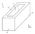
도1은 본 발명에 의한 도가니의 예시적인 실시예를 나타내는 투시도이다.
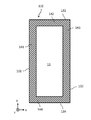
도2는 도1의 도가니의 평면도이다.
도3은 도1의 도가니의 저면도이다.
도4는 도가니의 다른 일 실시예의 저면도이다.
도5는 도3에 도시된 A-A’선을 따른 도1의 도가니의 횡단면도이다.
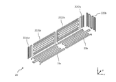
도6은 본 발명에 의한 재료를 증발 또는 승화시키기 위한 시스템의 일부분으로서의 히터 구성의 예시적 실시예를 나타내는 도면이다.
도7은 본 발명에 의한 재료를 증발 또는 승화시키기 위한 시스템의 예시적 실시예를 구비하는 증발 또는 승화를 위한 처리실을 나타내는 횡단면도이다.The drawings are included in the text to assist in understanding embodiments of the invention and are included in the specification of the present invention and constitute a part of the specification of the present invention. The drawings are intended to illustrate embodiments of the invention and to explain principles together with the specification of the invention. It is to be understood that other embodiments of the invention and many of the foreseeable advantages are readily apparent as the following detailed description and such embodiments and possible advantages become more apparent. The components of the drawings are not necessarily reduced / enlarged in proportion to each other. Like numerals denote corresponding parts.
1 is a perspective view showing an exemplary embodiment of a crucible according to the present invention.
2 is a plan view of the crucible of Fig.
3 is a bottom view of the crucible of Fig.
4 is a bottom view of another embodiment of the crucible.
Fig. 5 is a cross-sectional view of the crucible of Fig. 1 taken along the line A-A 'shown in Fig. 3;
6 is a diagram showing an exemplary embodiment of a heater arrangement as part of a system for evaporating or sublimating a material according to the present invention.
7 is a cross-sectional view illustrating a process chamber for evaporation or sublimation having an exemplary embodiment of a system for evaporating or sublimating a material according to the present invention.
도1은 본 발명에 의한 도가니(10)의 예시적인 실시예를 나타내는 도면이다. 도가니(10)는 흑연 또는 임의의 기타 적합한 재료로 제작된 장방체이고 또한 6개의 표면 즉 상부 표면인 제1 표면(110); 저부 표면인 제2 표면(이 도면에서는 보이지 않음); 및 4개의 측부 표면을 구비하며, 이 도면에서 단지 그 중의 두 측부 표면(133 및 134)만 보인다. 오목한 리세스(11)는 제1 표면(110)에 형성되고, 그 중에서 오목한 리세스(11)는 증발 또는 승화시키고자 하는 재료를 용납하기 적합하다. 오목한 리세스(11)는 제1 표면에 개구를 구비하고 또한 임의의 적합한 형식과 임의의 적합한 치수를 가질 수 있다. 그리고 도가니(10)는 하나 이상의 오목한 리세스(11)를 구비할 수 있다. 예를 들면, 도가니는 복수의 오목한 리세스를 구비할 수 있는 바, 그 중에서 오목한 리세스의 각각은 제1 표면에서 기둥형 홀로 형성되고 또한 오목한 리세스 중의 서로 다른 오목한 리세스는 도가니의 재료에 의하여 서로 분리된다.1 is a view showing an exemplary embodiment of a
도2는 도가니(10)의 평면도이고 또한 이로써 제1 표면(110)을 도시하며, 오목한 리세스(11)는 제1 표면(110)에 형성된다. 도가니(10)의 재료가 도가니(10)의 측벽(141 내지 144)를 형성하고, 측벽(141 내지 144)은 오목한 리세스(11)로부터 도가니의 상응한 측부 표면(131 내지 134)으로 연장된다. 측벽(141 내지 144)은 제1 표면(110)으로부터 제2 표면으로 연장되는 바, 즉 z 방향에서 연장되고 또한 도가니(10)의 상부와 저부를 연결시킨다.Figure 2 is a plan view of the
도3은 도가니(10)의 저면도로서 또한 이로써 제1 표면(110)과 반대되는 제2 표면(120)을 도시한다. 저부 리세스(12)은 제2 표면(120)에 형성되고, 그 중에서 저부 리세스(12)는 도가니가 증발 또는 승화 과정에 사용될 때 저부 히터를 수용하는데 사용된다. 저부 리세스(12)는 임의의 적합한 형식과 치수를 가질 수 있다. 그리고 도3에서 측부 리세스(13a 내지 13d)의 개구를 볼 수 있다. 측부 리세스(13a 내지 13d)의 각각은 측벽(141 내지 144)중의 상응한 측벽에 형성되고 또한 z 방향에서 연장되는 바, 도4에서 곧 설명하게 될 내용과 같다. 제2 표면(120)의 측부 리세스(13a 내지 13d)의 개구의 횡방향 치수 및 측부 리세스(13a 내지 13d)의 횡방향 치수(모든 횡방향 치수는 모두 x 방향 또는 y 방향에서 측정한 것임)는 최대한 작아야 하는 바, 측부 히터를 측부 리세스(13a 내지 13d)에 삽입했을 때 손상되지 않고 또한 가열 기간에 측부 히터가 측부 리세스(13a 내지 13d)에서 열팽창 되는 것을 허용하기만 하면 된다. 그리고 각 측벽(141 내지 144)에서, 단열 리세스(14a 내지 14d)는 상응한 측부 리세스(13a 내지 13d)의 오목한 리세스에서 등지고 또한 상응한 측부 표면과 마주하는 측에 형성된다. 각 단열 리세스(14a 내지 14d)는 상응한 측벽(141 내지 144)의 재료에 의하여 둘러싸이고 또한 제2 표면(120)에 인접되게 개구가 구비된다. 바람직하게는, 단열 리세스(14a, 14c)는 y 방향 상에서 상응한 측부 리세스(13a, 13c)의 치수와 유사한 치수 또는 상응한 측부 리세스(13a, 13c)보다 더욱 큰 치수를 가진다.Figure 3 shows a bottom view of the
도4는 다른 도가니(10’)의 저면도이다. 도가니(10’)와 도가니(10)의 다른 점은 3개의 측부 리세스(13aa 내지 13ac와 13ca 내지 13cc)가 각 도가니의 측벽(141 및 142)의 각각에 형성된다는 것 뿐이다. 그리고 해당 도면이 더욱 명확하도록 도3에 도시된 단열 리세스를 도시하지 않았다. 측벽(141)의 측부 리세스(13aa 내지 13ac)는 각각 재료 바(141a 및 141b)를 통하여 측부 리세스(13aa 내지 13ac)의 인접된 측부 리세스와 분리된다. 재료 바(141a 및 141b)는 측벽(141)의 일부분이고 또한 상응한 측부 리세스(13aa 내지 13ac)의 상응한 측부 리세스 사이의 중간벽을 형성한다. 재료 바(141a 및 141b)는 제1 표면(110)으로부터 제2 표면(120)으로 연장된다. 재료 바(141a 및 141b)는 측벽(141)의 안정성을 향상시키고 또한 서로 다른 측부 히터를 상응한 측부 리세스(13aa 내지 13ac)에 삽입하도록 하여, 도가니(10’)의 측벽(141)에 인접되는 서로 다른 횡방향 구역이 독립적으로 가열되도록 하여 오목한 리세스에 용납되는 재료의 온도의 균일성을 더욱 향상시킨다. 측부 리세스(13aa 내지 13ac)와 측벽(141)에 대하여 설명한 특징은 측부 리세스(13ca 내지 13cc)와 측벽(143)에도 마찬가지로 적용된다.4 is a bottom view of another crucible 10 '. The only difference between the crucible 10 'and the
도5는 도3에 도시된 A-A’선에 따른 도가니(10)의 횡단면을 도시하고 있다. 횡단면도에서는, 제1 표면(110)의 오목한 리세스(11), 제2 표면(120)의 저부 리세스(12)와 측벽(141, 143)의 두 측부 리세스(13a, 13c)를 보여주고 있다. 측부 리세스(13a, 13c)는 z 방향을 따라 거의 도가니(10)의 전반 치수에서 연장되고 또한 제2 표면(120)에 인접되게 개구가 구비된다. 그리고 각 측벽(141, 143)에서, 단열 리세스(14a, 14c)는 상응한 측부 리세스(13a, 13c)의 오목한 리세스(11)에서 등지고 또한 상응한 측부 표면(131, 133)과 마주하는 측에 형성된다. 각 단열 리세스(14a, 14c)는 제2 표면(120)에 인접되게 개구를 구비한다. 예를 들면, 단열 리세스(14a, 14c)에는 공기가 충진되어 있을 수 있다. 단열 리세스(14a, 14c)는 x 방향 상에서 단지 도가니(10)의 전반 외부 치수와 도가니 자체의 안정성의 제한만 받는다. 제1 표면(110)을 향하는 z 방향 상에서, 단열 리세스(14a, 14c)는 상응한 측부 리세스(13a, 13c)와 동일한 값 또는 더욱 멀리 연장되는 것이 바람직하다.5 shows a cross section of the
표1에서는 도가니(10)와 도기니(10’)의 서로 다른 요소의 예시적 치수를 보여주고 있다. 명확하게 이해되는 바와 같이, 도가니(10’)은 유사한 치수를 가질 수 있고, 그 중에서 측부 리세스(13aa 내지 13ac와 13ca 내지 13cc)는 y 방향에서 비교적 작다.Table 1 shows exemplary dimensions of the different elements of the

도6은 도1 내지 도3에 도시된 도가니(10)을 가열하는 예시적 히터 구성(20)을 도시하고 있다. 히터 구성(20)에는 두 저부 히터(21a 및 21b), 도가니의 각 장측에 사용되는 두 모퉁이 히터와 두 중간 히터 및 도가니의 각 단측에 사용되는 한 측부 히터가 포함된다. 도6에서는, 도면이 더욱 명료하도록 도가니의 단측에 사용되는 한 측부 히터(223b), 도가니의 한 장측에 사용되는 모퉁이 히터(2211a 및 2212a)와 중간 히터(2221a 및 2222a) 및 두 저부 히터(21a 및 21b)만 도시하였다. 도가니의 장측에 사용되는 히터(2211a, 2212a, 2221a 및 2222a)의 각각은 상응한 측벽의 동일한 측부 리세스에 삽입되거나 또는 상응한 측벽에 형성된 서로 다른 측부 리세스에 삽입될 수 있다. 히터는 전도 회로로 형성된 저항 히터이다. 히터의 도선의 재료는 몰리브덴이나, 임의의 기타 적합한 재료일 수 잇다.Figure 6 shows an
도7은 증발 또는 승화에 사용되는 처리실(200)의 횡단면도이다. 처리실(200) 내에서, 본 발명에 의한 재료의 증발 또는 승화를 위한 시스템(210)은 설치판(220)에 설치되거나 또는 직접 실벽(230)에 설치된다. 시스템(210)에는 상기 도가니(10)와 히터 구성(20)이 포함된다. 오목한 리세스(11)는 증발 또는 승화시키고자 하는 재료(30)를 용납하고, 증발 또는 승화시키고자 하는 재료(30)는 상기 히터 구성의 히터에 의해 가열된다. 도5에 도시된 바와 같이, 히터는 저부 리세스 또는 측부 리세스에 설치되지만, 도면이 더욱 명료하도록 도7에서 저부 리세스와 측부 리세스를 도시하지 않았다. 그리고 동일한 원인으로 인하여, 도7에는 도5에 도시된 단열 리세스도 도시하지 않았다. 도7의 횡단면도에서, 단지 저부 히터(21a)와 두 모퉁이 히터(2211a 및 2211c)만 도시하였지만, 더욱 많은 히터가 상기 도6에 도시된 히터 구성에 포함될 수 있다. 그리고 도7에서는 저부 히터(21a)로 에너지를 공급하기 위한 에너지 공급 연결(241a 및 241b) 및 모퉁이 히터(2211a 및 2211c)로 각각 에너지를 공급하기 위한 에너지 공급 연결(242a 및 242c)을 도시하고 있다. 에너지 공급 연결(241a, 241b, 242a, 242b)은 처리실(200)의 외부로 가이드되고, 그 중에서 에너지 공급 연결(241a, 241b, 242a, 242b)은 하나 또는 그 보다 많은 발전기에 연결된다. 히터 구성의 히터가 발생하는 열로 인하여, 재료(30)가 증발 또는 승화되고 또한 기판(250)을 향하여 이동하는 바, 점선 화살표로 표시된 바와 같다. 기판(250)은 전송 롤러(260)를 통하여 시스템(210) 상방에 유지 및 이동된다. 기판(250)(기판(250)은 또한 기판 홀더에 배치되는 복수의 기판일 수 있음)은 실선 화살표로 표시되는 방향으로 처리실(200) 내에서 이동된다. 하지만 재료(30)의 정적 증착(즉 재료가 이동하지 않는 기판(250) 상에 증착됨)도 가능하다.7 is a cross-sectional view of the
당업계의 기술자들이 잘 알고 있는 바와 같이, 히터 구성의 히터는 어떻게 되든지 도가니(10)와 처리실(200)에 대해여 고정적이다. 동일한 상황은 도가니(10) 자체에도 적용된다. 즉 히터 구성의 히터는 상응한 리세스(저부 리세스 및/또는 측부 리세스) 내에 고정되거나, 설치판(220) 또는 실벽(230) 또는 하나 혹은 그 보다 많은 커버에 고정되거나 할 수 있고, 상기 하나 또는 그 보다 많은 커버는 도가니(10)의 저부 표면에 장착되고 또한 상응한 리세스를 밀봉시킨다. 그러므로 리세스가 시스템의 어떠한 부품에 의해서도 밀봉되지 않는다 하더라도, 히터는 도가니의 리세스로부터 떨어지지 않을 수 있다. 히터 구성의 히터를 도가니(10)의 상응한 리세스 내에 설치하기 위하여, 히터는 도가니의 리세스에 삽입 고정되거나 또는 도가니(10)가 상부로부터 고정된 히터에서 슬라이딩할 수 있다. 하지만 두 부품(도가니와 히터)이 이동가능하여, 히터가 도가니의 상응한 리세스에 삽입되게 할 수도 있다.As known to those skilled in the art, the heater of the heater configuration is fixed to the
히터 구성의 히터가 도가니(10) 내에 설치되기 때문에, 히터로부터 재료(10)로의 열 전달이 최적화된다. 히터가 설치된 도가니(10)의 리세스가 설치판(220)에 의하여 밀봉되어, 히터가 처리실(200) 내의 환경 기체 분위기의 영향을 받는 것을 효과적으로 방지하며, 그 중에서 상기 환경 기체 분위기는 히터의 재료에 대하여 부식성을 갖는 성분을 포함할 수 있다. 그리고 도가니(10)는 간단하게 도가니(10)를 들어 올려 설치판(220)으로부터 멀어지게 함으로서 히터와 분리될 수 있다. 그러므로 만일 제1 도가니(10)를 반드시 청소하여야 하거나 반드시 다른 재료(30)를 증발 또는 승화하여야 할 때, 히터 구성도 같이 해체할 필요가 없이 제1 도가니(10)를 제2 도가니(10)로 교체할 수 있다.Since the heater in the heater configuration is installed in the
상기 기재된 본 발명의 실시예는 설명을 위해 예시한 것이고 또한 본 발명은 이의 제한을 받지 않는다. 실시예의 어떠한 수정, 변화와 동등한 구성 및 조합은 본 발명의 범위에 속 할 것이다.The embodiments of the present invention described above are illustrated for illustrative purposes and the present invention is not limited thereto. Any modifications, changes, equivalents, and combinations of embodiments will fall within the scope of the present invention.
10: 도가니
110: 제1 표면
120: 제2 표면
131 내지 134: 측부 표면
141 내지 144: 측벽
141a, 141b, 43a, 143b: 측벽 중의 재료 바
11: 오목한 리세스
12: 저부 리세스
13a 내지 13d: 측부 리세스
14a, 14c: 단열 리세스
20: 히터 구성
21a, 21b: 저부 히터
2211a, 2212a: 모퉁이 히터
2221a, 2222a: 중간 히터
223: 측부 히터
200: 처리실
210: 증발 또는 승화를 위한 시스템
220: 설치판
230: 실벽
241a, 241b: 저부 히터를 위한 에너지 공급 연결
242a, 242c: 측부 히터를 위한 에너지 공급 연결
250: 기판
260: 전송 롤러10: Crucible
110: first surface
120: second surface
131 to 134: side surface
141 to 144: side wall
141a, 141b, 43a, 143b:
11: recessed recess
12: bottom recess
13a to 13d: side recesses
14a, 14c: Insulation recess
20: Heater construction
21a, 21b: bottom heater
2211a, 2212a: Corner heater
2221a, 2222a: intermediate heater
223: Side heater
200: Treatment room
210: System for evaporation or sublimation
220: Mounting plate
230:
241a, 241b: energy supply connection for bottom heater
242a, 242c: energy supply connection for the side heater
250: substrate
260: Transfer roller
Claims (10)
적어도 하나의 오목한 리세스와 저부 리세스 및/또는 측부 리세스를 포함하고,
상기 오목한 리세스는 상기 증발 또는 승화시키고자 하는 재료를 수용하는데 적합하고, 상기 오목한 리세스는 상기 도가니의 제1 표면에 형성되며; 상기 저부 리세스는 상기 도가니의 제2 표면에 형성되고, 상기 제2 표면은 제1 표면의 반대면이며, 또한 상기 측부 리세스는 상기 도가니의 측벽에 형성되고, 상기 측벽은 상기 제1 표면으로부터 상기 제2 표면으로 연장되며, 그 중에서 상기 측부 리세스는 상기 도가니의 상기 제2 표면에 인접되게 개구가 구비되는 것을 특징으로 하는 도가니.A crucible for heating a material to be evaporated or sublimated,
At least one recessed recess and a bottom recess and / or side recess,
The recessed recess is adapted to receive the material to be evaporated or sublimated, the recessed recess being formed in the first surface of the crucible; Wherein the bottom recess is formed in a second surface of the crucible, the second surface is an opposite surface of the first surface, and the side recess is formed in a sidewall of the crucible, And wherein the side recess is provided with an opening adjacent the second surface of the crucible.
상기 도가니는 복수의 측부 리세스를 포함하여 상기 도가니의 모든 측벽중의 각 측벽에 상기 측부 리세스 중의 하나의 서로 다른 측부 리세스가 형성되는 것을 특징으로 하는 도가니.The method according to claim 1,
Wherein the crucible includes a plurality of side recesses to form a different side recess in one of the side recesses on each side wall of all sidewalls of the crucible.
상기 도가니는 상기 측부 리세스를 포함하고 또한 단열 리세스를 더 포함하며, 상기 단열 리세스는 상기 측부 리세스의 상기 도가니의 상기 오목한 리세스에 인접되지 않는 일측에 있어서 상기 측부 리세스에 인접되게 상기 도가니의 동일 측벽 내에 형성되며, 그 중에서 상기 측부 리세스와 상기 단열 리세스는 상기 도가니의 재료에 의하여 서로 분리되는 것을 특징으로 하는 도가니.3. The method according to claim 1 or 2,
Wherein the crucible further comprises the side recess and the heat insulating recess is formed adjacent to the side recess at one side not adjacent to the recessed recess of the crucible of the side recess Wherein the crucible is formed in the same side wall of the crucible, and the side recess and the heat insulating recess are separated from each other by the material of the crucible.
상기 도가니는 높은 열전도율을 갖고 있는 또한 상기 증발 또는 승화시키고자 하는 재료에 대하거나 또는 환경 기체 분위기의 성분에 대하여 불활성이고 또한 확산되지 않는 재료로 제조되는 것을 특징으로 하는 도가니.4. The method according to any one of claims 1 to 3,
Wherein the crucible is made of a material which has a high thermal conductivity and which is inert to and not diffused to the material to be vaporized or sublimated or to the environmental gas atmosphere.
상기 도가니의 재료는 흑연, 탄화규소 및 산화물 세라믹 재료를 포함하는 재료 그룹으로부터 선택되는 것을 특징으로 하는 도가니.5. The method of claim 4,
Wherein the material of the crucible is selected from the group of materials comprising graphite, silicon carbide and an oxide ceramic material.
제1항 내지 제5항 중 어느 한 항의 상기 도가니와 상기 도가니를 가열하기 위한 히터 구성을 포함하고, 그 중에서 상기 히터 구성은 상기 도가니의 상기 저부 리세스 또는 상기 측부 리세스에 설치되는 적어도 하나의 히터를 포함하는 것을 특징으로 하는 시스템.A system for evaporating or sublimating a material,
A crucible according to any one of claims 1 to 5 and a heater arrangement for heating the crucible, wherein the heater arrangement comprises at least one of a bottom recess in the crucible or a bottom recess in the side recess And a heater.
상기 도가니는 복수의 측부 리세스를 포함하고 또한 상기 히터 구성은 복수의 히터를 포함하며, 그 중에서 상기 측부 리세스중의 각 측부 리세스에는 히터 중의 하나의 특정 히터가 설치되는 것을 특징으로 하는 시스템.The method according to claim 6,
Characterized in that the crucible comprises a plurality of side recesses and the heater arrangement comprises a plurality of heaters, of which one of the heaters is installed in each side recess during the side recess .
상기 적어도 하나의 히터는 상기 증발시키고자 하는 재료에 대하거나 또는 환경 기체 분위기의 성분에 대하여 비 불활성인 재료로 제조되는 것을 특징으로 하는 시스템.8. The method according to claim 6 or 7,
Wherein the at least one heater is made of a material that is non-inert to the material to be vaporized or to a component of an environmental gas atmosphere.
상기 적어도 하나의 히터는 높은 열전도율을 갖고 있는 또한 상기 증발 또는 승화시키고자 하는 재료에 대하거나 또는 환경 기체 분위기의 성분에 대하여 불활성이고 또한 확산되지 않는 재료가 코팅되는 것을 특징으로 하는 시스템.9. The method of claim 8,
Wherein said at least one heater is coated with a material which has a high thermal conductivity and which is inert with respect to the material to be vaporized or sublimated or which is inert to the components of the environmental atmosphere and is not diffused.
상기 시스템은 적어도 하나의 커버를 더 포함하고, 상기 적어도 하나의 커버는 상기 도가니의 상기 저부 리세스 또는 상기 측부 리세스 중의 적어도 하나를 밀봉시켜 환경 기체 분위기의 영향을 받지 않도록 하는 것을 특징으로 하는 시스템.10. The method according to any one of claims 6 to 9,
Wherein the system further comprises at least one cover, wherein the at least one cover seals at least one of the bottom recess or the side recess of the crucible such that it is not affected by the ambient environment of the environment .
Applications Claiming Priority (3)
| Application Number | Priority Date | Filing Date | Title |
|---|---|---|---|
| CN201511026677.3 | 2015-12-31 | ||
| CN201511026677.3A CN106929805B (en) | 2015-12-31 | 2015-12-31 | Crucible for containing and heating a material and system comprising a crucible and a heater arrangement |
| PCT/CN2016/112150 WO2017114364A1 (en) | 2015-12-31 | 2016-12-26 | Crucible for accommodating and heating material, and system comprising arranged crucible and heater |
Publications (2)
| Publication Number | Publication Date |
|---|---|
| KR20180098668A true KR20180098668A (en) | 2018-09-04 |
| KR102138990B1 KR102138990B1 (en) | 2020-07-29 |
Family
ID=59225890
Family Applications (1)
| Application Number | Title | Priority Date | Filing Date |
|---|---|---|---|
| KR1020187022190A Active KR102138990B1 (en) | 2015-12-31 | 2016-12-26 | A system comprising a crucible for melting and heating the material and a crucible and heater configuration |
Country Status (6)
| Country | Link |
|---|---|
| US (1) | US20190119807A1 (en) |
| EP (1) | EP3399069B1 (en) |
| JP (1) | JP6681125B2 (en) |
| KR (1) | KR102138990B1 (en) |
| CN (1) | CN106929805B (en) |
| WO (1) | WO2017114364A1 (en) |
Cited By (1)
| Publication number | Priority date | Publication date | Assignee | Title |
|---|---|---|---|---|
| KR102198114B1 (en) * | 2020-09-16 | 2021-01-04 | 조슬기 | Multi-year ginseng hydroponic cultivation system with Carbon dioxide supply system for hydroponic cultivation |
Families Citing this family (3)
| Publication number | Priority date | Publication date | Assignee | Title |
|---|---|---|---|---|
| CN107805782B (en) * | 2017-11-27 | 2019-09-20 | 深圳市华星光电半导体显示技术有限公司 | A kind of evaporation coating device |
| JP7018816B2 (en) * | 2018-04-26 | 2022-02-14 | 昭和電工株式会社 | Crucible and SiC single crystal growth device |
| US20220228250A1 (en) * | 2021-01-15 | 2022-07-21 | Phoenix Silicon International Corp. | Crucible and vapor deposition apparatus |
Citations (8)
| Publication number | Priority date | Publication date | Assignee | Title |
|---|---|---|---|---|
| JPH0610118A (en) * | 1992-06-29 | 1994-01-18 | Nec Kansai Ltd | Vapor deposition method and evaporation device |
| JP2003166049A (en) * | 2001-11-28 | 2003-06-13 | Murata Mfg Co Ltd | Crucible for vapor deposition |
| JP2007270261A (en) * | 2006-03-31 | 2007-10-18 | Kyocera Corp | Vapor deposition apparatus, vapor deposition method, organic EL device manufacturing method, and vapor deposition cell |
| KR20080012748A (en) * | 2006-08-04 | 2008-02-12 | 순천향대학교 산학협력단 | Linear Deposition Sources for Deposition Processes |
| CN101550532A (en) * | 2009-05-14 | 2009-10-07 | 苏州大学 | Heating device used for vacuum plating equipment |
| WO2013001827A1 (en) * | 2011-06-29 | 2013-01-03 | パナソニック株式会社 | Heating apparatus, vacuum-heating method and method for manufacturing thin film |
| CN203639543U (en) * | 2013-12-16 | 2014-06-11 | 中国电子科技集团公司第十八研究所 | Selenium source evaporation device |
| KR20150081008A (en) * | 2014-01-03 | 2015-07-13 | 삼성디스플레이 주식회사 | Deposition source |
Family Cites Families (8)
| Publication number | Priority date | Publication date | Assignee | Title |
|---|---|---|---|---|
| US3636305A (en) * | 1971-03-10 | 1972-01-18 | Gte Sylvania Inc | Apparatus for metal vaporization comprising a heater and a refractory vessel |
| WO2008016247A1 (en) * | 2006-08-04 | 2008-02-07 | Soonchunhyang University Industry Academy Cooperation Foundation | Linear deposition sources for deposition processes |
| DE112009003667B4 (en) * | 2008-12-08 | 2024-04-25 | Ii-Vi Inc. | IMPROVED AXIAL GRADIENT TRANSPORT (AGT) GROWTH METHOD AND APPARATUS USING RESISTIVE HEATING |
| KR101456831B1 (en) * | 2012-06-20 | 2014-11-03 | 엘지디스플레이 주식회사 | Heating Apparatus for Manufacturing Display Device |
| KR20150072828A (en) * | 2013-12-20 | 2015-06-30 | 엘지디스플레이 주식회사 | Deposition source unit for manufacturing organic light emitting device |
| CN106103790B (en) * | 2014-03-11 | 2018-12-07 | 株式会社日本有机雷特显示器 | Evaporation device and control method thereof, vapor deposition method using vapor deposition device, and device manufacturing method |
| DE102014007521A1 (en) * | 2014-05-23 | 2015-11-26 | Manz Ag | Evaporator source for the surface treatment of substrates |
| CN104357797B (en) * | 2014-11-14 | 2017-01-18 | 京东方科技集团股份有限公司 | Heater for crucible, crucible and evaporation source |
-
2015
- 2015-12-31 CN CN201511026677.3A patent/CN106929805B/en active Active
-
2016
- 2016-12-26 EP EP16881153.7A patent/EP3399069B1/en active Active
- 2016-12-26 US US16/064,423 patent/US20190119807A1/en not_active Abandoned
- 2016-12-26 WO PCT/CN2016/112150 patent/WO2017114364A1/en not_active Ceased
- 2016-12-26 JP JP2018553289A patent/JP6681125B2/en active Active
- 2016-12-26 KR KR1020187022190A patent/KR102138990B1/en active Active
Patent Citations (8)
| Publication number | Priority date | Publication date | Assignee | Title |
|---|---|---|---|---|
| JPH0610118A (en) * | 1992-06-29 | 1994-01-18 | Nec Kansai Ltd | Vapor deposition method and evaporation device |
| JP2003166049A (en) * | 2001-11-28 | 2003-06-13 | Murata Mfg Co Ltd | Crucible for vapor deposition |
| JP2007270261A (en) * | 2006-03-31 | 2007-10-18 | Kyocera Corp | Vapor deposition apparatus, vapor deposition method, organic EL device manufacturing method, and vapor deposition cell |
| KR20080012748A (en) * | 2006-08-04 | 2008-02-12 | 순천향대학교 산학협력단 | Linear Deposition Sources for Deposition Processes |
| CN101550532A (en) * | 2009-05-14 | 2009-10-07 | 苏州大学 | Heating device used for vacuum plating equipment |
| WO2013001827A1 (en) * | 2011-06-29 | 2013-01-03 | パナソニック株式会社 | Heating apparatus, vacuum-heating method and method for manufacturing thin film |
| CN203639543U (en) * | 2013-12-16 | 2014-06-11 | 中国电子科技集团公司第十八研究所 | Selenium source evaporation device |
| KR20150081008A (en) * | 2014-01-03 | 2015-07-13 | 삼성디스플레이 주식회사 | Deposition source |
Cited By (1)
| Publication number | Priority date | Publication date | Assignee | Title |
|---|---|---|---|---|
| KR102198114B1 (en) * | 2020-09-16 | 2021-01-04 | 조슬기 | Multi-year ginseng hydroponic cultivation system with Carbon dioxide supply system for hydroponic cultivation |
Also Published As
| Publication number | Publication date |
|---|---|
| US20190119807A1 (en) | 2019-04-25 |
| JP6681125B2 (en) | 2020-04-15 |
| CN106929805B (en) | 2022-02-25 |
| EP3399069A1 (en) | 2018-11-07 |
| KR102138990B1 (en) | 2020-07-29 |
| CN106929805A (en) | 2017-07-07 |
| JP2019506536A (en) | 2019-03-07 |
| EP3399069A4 (en) | 2019-10-16 |
| WO2017114364A1 (en) | 2017-07-06 |
| EP3399069B1 (en) | 2021-12-08 |
Similar Documents
| Publication | Publication Date | Title |
|---|---|---|
| US12286704B2 (en) | Thermal evaporation sources for wide-area deposition | |
| KR20180098668A (en) | A system comprising crucible and crucible and heater arrangement to tolerate and heat the material | |
| WO2008079209A1 (en) | Vapor deposition sources and methods | |
| TW201425638A (en) | Substrate processing apparatus, manufacturing method of semiconductor device, and recording medium | |
| CA2388178A1 (en) | Method and apparatus for coating a substrate in a vacuum | |
| CN105849311B (en) | The reative cell for epitaxial growth with loading/discharge mechanism and reactor | |
| KR102003199B1 (en) | Substrate Processing Apparatus | |
| KR20170084278A (en) | Cvd or pvd reactor for coating large-area substrates | |
| TW202042275A (en) | Substrate mounting table capable of improving temperature control precision and plasma treatment equipment | |
| US20110275196A1 (en) | Thermal Evaporation Sources with Separate Crucible for Holding the Evaporant Material | |
| US20040200416A1 (en) | Effusion cell with improved temperature control of the crucible | |
| KR20210151151A (en) | Source arrangement, deposition apparatus and method for depositing source material | |
| KR102538550B1 (en) | carrying ring | |
| KR101499054B1 (en) | Effusion Cell for Antipollution of Inner Part | |
| KR101582672B1 (en) | Crucible for evaporation, vacuum effusion cell and vacuum deposition apparatus including the same | |
| JP6116685B2 (en) | Apparatus and method for heat treating an object | |
| EP3314034A1 (en) | Evaporation crucible with floater | |
| WO2017114367A1 (en) | Heater device for heating crucible, operation method therefor and crucible for containing and heating material to be evaporated or sublimated | |
| KR102687835B1 (en) | Appratus for measuring temperature, and apparatus for processing substrate having the same | |
| KR101909210B1 (en) | evaporation source and thin flim deposition apparatus having the same | |
| KR100889761B1 (en) | Heating vessel of organic thin film forming apparatus | |
| KR20080090628A (en) | Thin film manufacturing vacuum evaporation apparatus and top down vacuum evaporation apparatus using the same | |
| KR20080002523A (en) | Organic light emitting device deposition apparatus |
Legal Events
| Date | Code | Title | Description |
|---|---|---|---|
| A201 | Request for examination | ||
| PA0105 | International application |
St.27 status event code: A-0-1-A10-A15-nap-PA0105 |
|
| PA0201 | Request for examination |
St.27 status event code: A-1-2-D10-D11-exm-PA0201 |
|
| PG1501 | Laying open of application |
St.27 status event code: A-1-1-Q10-Q12-nap-PG1501 |
|
| E902 | Notification of reason for refusal | ||
| PE0902 | Notice of grounds for rejection |
St.27 status event code: A-1-2-D10-D21-exm-PE0902 |
|
| E13-X000 | Pre-grant limitation requested |
St.27 status event code: A-2-3-E10-E13-lim-X000 |
|
| P11-X000 | Amendment of application requested |
St.27 status event code: A-2-2-P10-P11-nap-X000 |
|
| P13-X000 | Application amended |
St.27 status event code: A-2-2-P10-P13-nap-X000 |
|
| E701 | Decision to grant or registration of patent right | ||
| PE0701 | Decision of registration |
St.27 status event code: A-1-2-D10-D22-exm-PE0701 |
|
| GRNT | Written decision to grant | ||
| PR0701 | Registration of establishment |
St.27 status event code: A-2-4-F10-F11-exm-PR0701 |
|
| PR1002 | Payment of registration fee |
St.27 status event code: A-2-2-U10-U12-oth-PR1002 Fee payment year number: 1 |
|
| PG1601 | Publication of registration |
St.27 status event code: A-4-4-Q10-Q13-nap-PG1601 |
|
| PR1001 | Payment of annual fee |
St.27 status event code: A-4-4-U10-U11-oth-PR1001 Fee payment year number: 4 |
|
| PR1001 | Payment of annual fee |
St.27 status event code: A-4-4-U10-U11-oth-PR1001 Fee payment year number: 5 |
|
| PR1001 | Payment of annual fee |
St.27 status event code: A-4-4-U10-U11-oth-PR1001 Fee payment year number: 6 |
|
| U11 | Full renewal or maintenance fee paid |
Free format text: ST27 STATUS EVENT CODE: A-4-4-U10-U11-OTH-PR1001 (AS PROVIDED BY THE NATIONAL OFFICE) Year of fee payment: 6 |