KR20180098643A - A new method for synchronously cutting a continuously formed material to a fixed length using a series-connected multi-cutter holder - Google Patents
A new method for synchronously cutting a continuously formed material to a fixed length using a series-connected multi-cutter holder Download PDFInfo
- Publication number
- KR20180098643A KR20180098643A KR1020187021810A KR20187021810A KR20180098643A KR 20180098643 A KR20180098643 A KR 20180098643A KR 1020187021810 A KR1020187021810 A KR 1020187021810A KR 20187021810 A KR20187021810 A KR 20187021810A KR 20180098643 A KR20180098643 A KR 20180098643A
- Authority
- KR
- South Korea
- Prior art keywords
- cutter
- cutter holder
- holder
- cutting
- speed
- Prior art date
- Legal status (The legal status is an assumption and is not a legal conclusion. Google has not performed a legal analysis and makes no representation as to the accuracy of the status listed.)
- Ceased
Links
Images

Classifications
-
- B—PERFORMING OPERATIONS; TRANSPORTING
- B23—MACHINE TOOLS; METAL-WORKING NOT OTHERWISE PROVIDED FOR
- B23D—PLANING; SLOTTING; SHEARING; BROACHING; SAWING; FILING; SCRAPING; LIKE OPERATIONS FOR WORKING METAL BY REMOVING MATERIAL, NOT OTHERWISE PROVIDED FOR
- B23D21/00—Machines or devices for shearing or cutting tubes
-
- B—PERFORMING OPERATIONS; TRANSPORTING
- B21—MECHANICAL METAL-WORKING WITHOUT ESSENTIALLY REMOVING MATERIAL; PUNCHING METAL
- B21C—MANUFACTURE OF METAL SHEETS, WIRE, RODS, TUBES, PROFILES OR LIKE SEMI-MANUFACTURED PRODUCTS OTHERWISE THAN BY ROLLING; AUXILIARY OPERATIONS USED IN CONNECTION WITH METAL-WORKING WITHOUT ESSENTIALLY REMOVING MATERIAL
- B21C37/00—Manufacture of metal sheets, rods, wire, tubes, profiles or like semi-manufactured products, not otherwise provided for; Manufacture of tubes of special shape
- B21C37/06—Manufacture of metal sheets, rods, wire, tubes, profiles or like semi-manufactured products, not otherwise provided for; Manufacture of tubes of special shape of tubes or metal hoses; Combined procedures for making tubes, e.g. for making multi-wall tubes
- B21C37/08—Making tubes with welded or soldered seams
- B21C37/0807—Tube treating or manipulating combined with, or specially adapted for use in connection with tube making machines, e.g. drawing-off devices, cutting-off
-
- B—PERFORMING OPERATIONS; TRANSPORTING
- B21—MECHANICAL METAL-WORKING WITHOUT ESSENTIALLY REMOVING MATERIAL; PUNCHING METAL
- B21F—WORKING OR PROCESSING OF METAL WIRE
- B21F11/00—Cutting wire
-
- B—PERFORMING OPERATIONS; TRANSPORTING
- B23—MACHINE TOOLS; METAL-WORKING NOT OTHERWISE PROVIDED FOR
- B23B—TURNING; BORING
- B23B1/00—Methods for turning or working essentially requiring the use of turning-machines; Use of auxiliary equipment in connection with such methods
-
- B—PERFORMING OPERATIONS; TRANSPORTING
- B23—MACHINE TOOLS; METAL-WORKING NOT OTHERWISE PROVIDED FOR
- B23B—TURNING; BORING
- B23B3/00—General-purpose turning-machines or devices, e.g. centre lathes with feed rod and lead screw; Sets of turning-machines
-
- B—PERFORMING OPERATIONS; TRANSPORTING
- B23—MACHINE TOOLS; METAL-WORKING NOT OTHERWISE PROVIDED FOR
- B23B—TURNING; BORING
- B23B5/00—Turning-machines or devices specially adapted for particular work; Accessories specially adapted therefor
- B23B5/14—Cutting-off lathes
-
- B—PERFORMING OPERATIONS; TRANSPORTING
- B23—MACHINE TOOLS; METAL-WORKING NOT OTHERWISE PROVIDED FOR
- B23D—PLANING; SLOTTING; SHEARING; BROACHING; SAWING; FILING; SCRAPING; LIKE OPERATIONS FOR WORKING METAL BY REMOVING MATERIAL, NOT OTHERWISE PROVIDED FOR
- B23D23/00—Machines or devices for shearing or cutting profiled stock
-
- B—PERFORMING OPERATIONS; TRANSPORTING
- B23—MACHINE TOOLS; METAL-WORKING NOT OTHERWISE PROVIDED FOR
- B23D—PLANING; SLOTTING; SHEARING; BROACHING; SAWING; FILING; SCRAPING; LIKE OPERATIONS FOR WORKING METAL BY REMOVING MATERIAL, NOT OTHERWISE PROVIDED FOR
- B23D25/00—Machines or arrangements for shearing stock while the latter is travelling otherwise than in the direction of the cut
- B23D25/02—Flying shearing machines
- B23D25/04—Flying shearing machines in which a cutting unit moves bodily with the work while cutting
-
- B—PERFORMING OPERATIONS; TRANSPORTING
- B23—MACHINE TOOLS; METAL-WORKING NOT OTHERWISE PROVIDED FOR
- B23D—PLANING; SLOTTING; SHEARING; BROACHING; SAWING; FILING; SCRAPING; LIKE OPERATIONS FOR WORKING METAL BY REMOVING MATERIAL, NOT OTHERWISE PROVIDED FOR
- B23D31/00—Shearing machines or shearing devices covered by none or more than one of the groups B23D15/00 - B23D29/00; Combinations of shearing machines
-
- B—PERFORMING OPERATIONS; TRANSPORTING
- B23—MACHINE TOOLS; METAL-WORKING NOT OTHERWISE PROVIDED FOR
- B23D—PLANING; SLOTTING; SHEARING; BROACHING; SAWING; FILING; SCRAPING; LIKE OPERATIONS FOR WORKING METAL BY REMOVING MATERIAL, NOT OTHERWISE PROVIDED FOR
- B23D33/00—Accessories for shearing machines or shearing devices
- B23D33/006—Accessories for shearing machines or shearing devices for obtaining pieces of a predetermined length, e.g. control arrangements
-
- B—PERFORMING OPERATIONS; TRANSPORTING
- B23—MACHINE TOOLS; METAL-WORKING NOT OTHERWISE PROVIDED FOR
- B23B—TURNING; BORING
- B23B2215/00—Details of workpieces
- B23B2215/72—Tubes, pipes
Landscapes
- Engineering & Computer Science (AREA)
- Mechanical Engineering (AREA)
- Shearing Machines (AREA)
- Sawing (AREA)
Abstract
강관, 형강 등 재료를 연속적으로 성형하는 생산 라인에 있어서 직렬연결된 복수의 커터 홀더가 연속적으로 성형되는 재료를 동기적으로 고정길이로 절단하는 방법으로서, 직렬연결된 멀티 커터 홀더 동기화 고정길이 절단기를 포함하고, 이 절단기는 커터(7)가 설치된 2대 이상의 커터 홀더(1)와 커터 홀더(2)를 갖고, 이들 커터 홀더는 재료에 평행한 레일에 직렬로 설치되며, 각 구동장치(6 또는 5)의 구동에 의해, 설정된 절차에 따라 왕복 이동하여, 재료(3)의 속도와 동기화된 상태에서, 커터 홀더의 커터(9 또는 7)가 설정된 길이로 재료를 절단한다. 이러한 절단기는 고속 생산 라인에 적합하고, 허용되는 최소 고정길이가 짧고, 커터의 수명이 길며, 절단부의 품질이 좋다.A method for cutting a continuously synchronously fixed length of a material to be continuously formed by a plurality of cutter holders connected in series in a production line for continuously forming a material such as a steel pipe or a section steel, This cutter has two or more cutter holders 1 and a cutter holder 2 provided with a cutter 7. These cutter holders are installed in series with rails parallel to the material and are connected to the respective drive devices 6 or 5, The cutter 9 or 7 of the cutter holder cuts the material to a predetermined length in a state synchronized with the speed of the material 3 by the reciprocating movement according to the set procedure. These cutters are suitable for high speed production lines, have a minimum allowable fixing length, have a long cutter life, and have good cut quality.
Description
본 발명은 강관, 형강 등 재료를 연속적으로 성형하는 생산 라인 분야에 있어서, 절단기와 생산 라인 속도가 동기화된 상태에서, 재료를 설정된 길이로 절단하는 새로운 방법에 관한 것으로서, 구체적으로는, 직렬연결된 멀티 커터 홀더를 이용하여 연속적으로 성형되는 재료를 동기적으로(synchronously) 고정 길이로 절단하는 새로운 방법에 관한 것이다.The present invention relates to a new method for cutting a material to a predetermined length in a state of a production line in which materials such as steel tubes and sections are continuously formed in a state in which the speeds of a cutting machine and a production line are synchronized. To a new method for synchronously cutting a continuously formed material to a fixed length using a cutter holder.
종래에는, 강관, 형강 등 재료를 연속적으로 성형하는 생산 라인에 있어서, 대부분의 절단기는 싱글 커터 홀더 동기화 고정길이 절단기로써, 커터가 설치된 커터 홀더는 한 대뿐이어서, 재료가 설정된 길이만큼 이동하면, 커터 홀더는 재료에 평행한 레일 위를 원점부터 시작하여, 재료를 따라 이동하여, 커터 홀더의 속도와 재료의 속도가 동기화되면, 커터 홀더의 커터가 재료를 절단하고, 그 후 커터 홀더는 원점으로 돌아가, 다음 절단을 위한 준비를 한다. 커터 홀더의 행정은 1회 절단 과정이 완료된 후 커터 홀더가 원점으로 돌아가는데 충분한 시간을 확보하기 위해 재료의 고정길이보다 짧다. 생산 라인의 속도가 빠를수록, 재료의 고정길이가 짧을수록, 커터가 재료를 절단하는 시간이 짧아진다. 이러한 절단기는 고정길이가 짧은 제품의 절단에 적합하지 않으며, 고속 생산 라인에도 적합하지 않다. 그것은 절단 시간이 짧아서, 재료의 절단부의 품질이 떨어지고, 커터의 수명도 짧아지게 되기 때문이다. 따라서, 새로운 절단 방법을 개발할 필요가 있다.Conventionally, in a production line for continuously forming a material such as a steel pipe or a section steel, most of the cutters are single-cutter holder synchronous fixed length cutters, with only one cutter holder provided with a cutter. The holder moves along the material starting from the origin on a rail parallel to the material, so that when the speed of the cutter holder and the speed of the material are synchronized, the cutter of the cutter holder cuts the material and then the cutter holder returns to the origin , Prepare for the next cut. The stroke of the cutter holder is shorter than the fixed length of the material to ensure sufficient time for the cutter holder to return to the origin after one cutting process is completed. The faster the speed of the production line, the shorter the fixed length of the material, the shorter the time the cutter cuts the material. These cutters are not suitable for cutting products with short fixed lengths and are not suitable for high speed production lines. This is because the cutting time is short, the quality of the cut portion of the material is deteriorated, and the life of the cutter is also shortened. Therefore, it is necessary to develop a new cutting method.
종래 기술의 단점을 극복하기 위하여, 본 발명은 직렬연결된 멀티 커터 홀더를 이용하여 연속적으로 성형되는 재료를 동기적으로 고정길이로 절단하는 새로운 방법을 제공한다.In order to overcome the disadvantages of the prior art, the present invention provides a novel method of cutting a continuously shaped material to a synchronously fixed length using a serially connected multi-cutter holder.
본 발명의 구체적 기술 방안은, 커터가 설치된 2대 이상의 커터 홀더를 구비하고, 이들 커터 홀더는 재료에 평행한 레일에 직렬로 설치되고, 각 구동장치의 구동에 의해, 설정된 절차에 따라 왕복 이동하여, 재료의 속도와 동기화된 상태에서, 커터 홀더의 커터가 설정된 길이로 재료를 절단한다. 설명의 편의를 위하여, 도 1에 도시된 직렬연결된 더블(double) 커터 홀더 동기화 고정길이 절단기를 예로 그 동작 과정을 설명한다.A specific technical solution of the present invention is to include two or more cutter holders provided with a cutter and these cutter holders are installed in series with rails parallel to the material and are reciprocated , The cutter of the cutter holder cuts the material to the set length in synchronized with the speed of the material. For convenience of explanation, the operation of the double-cutter holder synchronization fixed-length cutter shown in FIG. 1 will be described as an example.
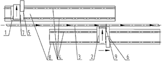
직렬연결된 더블 커터 홀더 동기화 고정길이 절단기를 나타낸 도 1을 살펴본다.1, which shows a serial-connected double cutter holder synchronous fixed length cutter.
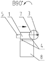
직렬연결된 더블 커터 홀더 동기화 고정길이 절단기는 2대의 커터 홀더를 구비하고, 커터 홀더(1) 및 커터 홀더(2)는 재료(3)에 평행한 레일(4)에 직렬로 설치되며, 상기 커터 홀더(1)와 커터 홀더(2)는 동일한 레일에 설치될 수도 있고, 각각의 레일에 설치될 수도 있다. 도 5에 나타낸 바와 같이, 레일(4)의 아래쪽에는 고정 베이스(8)가 있다. 커터 홀더(1)와 커터 홀더(2)는 각 구동장치(5, 6)의 구동에 의해, 설정된 절차에 따라 레일 위를 왕복 이동하고, 커터 홀더(1)에는 커터(7)가 설치되고, 커터 홀더(2)에는 커터(9)가 설치되어, 모두 재료(3)를 절단하는 데에 사용된다. 이 절단기의 절단 동작 사이클은 아래와 같다.The cutter holder (1) and the cutter holder (2) are installed in series with the rail (4) parallel to the material (3), and the cutter holder The
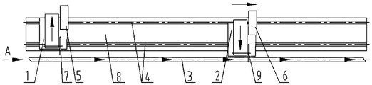
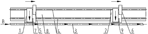
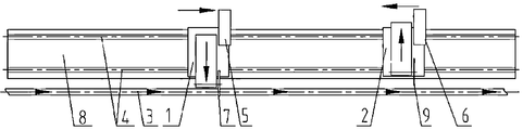
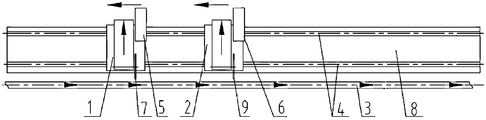
도 1을 참조하면, 재료(3)가 연속적으로 성형되는 과정에, 재료(3)가 커터 홀더(2)의 절단 범위에 진입하여 설정된 길이가 되면, 구동장치(6)가 동작을 개시하여, 커터 홀더(2)를 구동시켜 시작점에서부터 가속화하여, 커터 홀더(2)의 속도와 재료(3)의 속도가 동기화되면, 커터 홀더(2)의 커터(9)가 재료(3)를 절단하기 시작한다. 도 2를 참조하면, 재료(3)가 계속 앞으로 이동하여 커터 홀더(1)의 절단 범위에 진입하여 설정된 길이가 되면, 구동장치(5)가 동작을 개시하여, 커터 홀더(1)를 구동시켜 시작점에서부터 가속화하여, 커터 홀더(1)의 속도가 재료(3)의 속도와 동기화되면, 커터 홀더(1)의 커터(7)가 재료(3)를 절단하기 시작한다. 도 3을 참조하면, 커터 홀더(2)는 재료(3)를 절단한 후 시작점으로 되돌아간다. 도 4를 참조하면, 커터 홀더(1)는 재료(3)를 절단한 후 시작점으로 되돌아간다. 재료의 연속적인 성형에 따라, 절단기는 위의 동작 과정을 반복하여, 설정된 길이로 재료를 절단한다. 이상으로부터 알 수 있듯이, 싱글 커터 홀더 동기화 고정길이 절단기에 비하여, 직렬연결된 더블 커터 홀더 동기화 고정길이 절단기의 커터 홀더의 행정은 재료의 고정길이보다 길어 질 수 있다. 또한 직렬연결된 더블 커터 홀더 동기화 고정길이 절단기의 각 커터 홀더를 보면, 하나의 절단 사이클은 생산 라인이 두 개의 재료를 생산하는 시간에 해당하며, 두 개의 재료를 생산하는 과정에서 각 커터 홀더는 단 한번의 가속 및 감속 과정이 있다. 하지만, 싱글 커터 홀더 동기화 고정길이 절단기의 커터 홀더의 행정은 반드시 재료의 고정 길이보다 짧게 해야 하며, 하나의 절단 사이클은 생산 라인이 한 개의 재료를 생산하는 시간에 해당하며, 두 개의 재료를 생산하는 과정에서 커터 홀더는 두 번의 가속 및 감속 과정을 갖는다. 이로부터 알 수 있듯이, 직렬연결된 더블 커터 홀더 동기화 고정길이 절단기는 싱글 커터 홀더 동기화 고정길이 절단기보다 재료를 절단하는데 많은 시간을 가질 수 있다. 따라서 생산 라인의 속도 및 고정길이가 같은 경우, 직렬연결된 더블 커터 홀더 동기화 고정길이 절단기의 절단부 품질이 더 좋고, 커터의 수명도 더 길다. 즉, 절단부 품질과 커터의 수명이 동일한 경우, 직렬연결된 더블 커터 홀더 동기화 고정길이 절단기의 생산 라인 속도를 더 빠르게 할 수 있고, 재료의 고정길이를 더 짧게 할 수 있다. 또한, 제품의 수량이 같은 경우, 직렬연결된 더블 커터 홀더 동기화 고정길이 절단기의 각 절단 동작 횟수는 싱글 커터 홀더 동기화 고정길이 절단기보다 반으로 감소되기 때문에, 커터의 교환에 의한 생산 라인의 정지 횟수가 줄어들고, 생산 라인의 효율을 향상시키는데 유리하여, 불량품의 손실을 줄일 수 있다.1, when the
직렬연결된 멀티 커터 홀더 동기화 고정길이 절단기의 동작 원리는, 상술한 직렬연결된 더블 커터 홀더 동기화 고정길이 절단기의 동작 원리와 유사하며, 2대 이상의 커터 홀더를 구비하고, 이들 커터 홀더는 재료에 평행한 레일에 직렬로 설치되고, 상기 레일은 동일한 레일일 수도 있고, 각각의 레일일 수도 있으며, 레일은 재료의 일측 또는 양측에 배치될 수 있다. 이들 커터 홀더는 각 구동장치의 구동에 의해, 설정된 절차에 따라 왕복 이동하고, 속도가 동기화된 상태에서 설정된 길이로 재료를 절단한다. 커터 홀더의 수량이 많을수록, 커터 홀더의 행정을 길게 할 수 있으므로, 커터가 재료를 절단하는 데에 사용되는 시간은 더 많아진다. 이러한 절단기는 고속 생산 라인에 적합하고, 허용되는 최소 고정 길이가 짧고, 커터의 수명이 길고, 절단부의 품질이 좋고, 커터 교환을 위한 절단기 정지 횟수가 적다.The operation principle of the synchronous multi-cutter holder synchronous fixed length cutter is similar to the operation principle of the above-described serial-connected double cutter holder synchronous fixed length cutter, and has two or more cutter holders, And the rails may be the same rail or the respective rails, and the rails may be disposed on one side or both sides of the material. These cutter holders reciprocate according to a set procedure by driving each driving device, and cut the material to a set length in a state in which the speed is synchronized. The larger the number of cutter holders, the longer the stroke of the cutter holder, and the more time the cutter is used to cut the material. Such cutters are suitable for high speed production lines, have a short minimum allowable fixing length, have a long life of the cutter, good quality of the cut portion, and a small number of cutter stoppages for exchanging the cutter.
도 1은 본 발명의 특정 실시예에 있어서 커터 홀더(1)가 시작점에 있고, 커터 홀더(2)가 재료(3)를 추적하여 절단하는 것을 나타내는 개략도이다.
도 2는 본 발명의 특정 실시예에 있어서 커터 홀더(1) 및 커터 홀더(2)가 재료(3)를 추적하여 절단하는 것을 나타내는 개략도이다.
도 3은 본 발명의 특정 실시예에 있어서 커터 홀더(1)가 재료(3)를 추적하여 절단하고, 커터 홀더(2)가 절단 종료 후 되돌아가는 것을 나타내는 개략도다.
도 4는 본 발명의 특정 실시예에 있어서 커터 홀더(1) 및 커터 홀더(2)가 절단 종료 후 되돌아가는 것을 나타내는 개략도이다.
도 5는 본 발명이 다른 레일을 갖는 것을 나타내는 개략도이다.
도 6은 커터 홀더(1)의 커터가 절단하지 않을 때의 모습을 나타낸 개략도이다.
도 7은 커터 홀더(1)의 커터가 절단할 때의 모습을 나타낸 개략도이다.Figure 1 is a schematic diagram showing that in a particular embodiment of the invention the
Fig. 2 is a schematic view showing that the
Fig. 3 is a schematic view showing that the cutter holder 1 traces and cuts the
4 is a schematic view showing that the
5 is a schematic view showing that the present invention has another rail.
6 is a schematic view showing a state in which the cutter of the
7 is a schematic view showing a state in which the cutter of the
본 발명의 실시예에 대하여, 직렬연결된 멀티 커터 홀더 동기화 고정길이 절단기의 일 실시 형태인 직렬연결된 더블 커터 홀더 동기화 고정길이 절단기를 참조하여 더욱 상세하게 설명한다. 직렬연결된 더블 커터 홀더 동기화 고정길이 절단기는, 주로 커터 홀더(1, 2), 레일(4), 베이스(8), 구동장치(5, 6), 커터(7, 9)를 포함한다. 커터 홀더(1, 2)는 재료(3)에 평행한 레일(4)에 직렬로 설치되고, 상기 레일은 동일한 레일일 수도 있고, 각각의 레일일 수도 있으며, 구동장치(5, 6)의 구동에 의해, 설정된 절차에 따라 레일(4) 위를 왕복 이동한다. 커터 홀더(1, 2)의 속도가 재료의 속도와 동기화된 상태에서, 커터 홀더의 커터는 설정된 길이로 번갈아 재료(3)를 절단한다. 도 1에 나타낸 바와 같이, 커터 홀더(1)는 자신의 시작점에 멈춰서 있고, 재료(3)가 커터 홀더(2)의 절단 범위에 진입하여 설정된 길이가 되면, 구동장치(6)가 동작 개시하여, 커터 홀더(2)를 구동시켜 시작점에서부터 가속화하여, 커터 홀더(2)의 속도가 재료(3)의 속도와 동기화되면, 커터 홀더(2)의 커터(9)가 재료(3)를 절단하기 시작한다. 도 2에 나타낸 바와 같이, 재료(3)가 계속 앞으로 이동하여 커터 홀더(1)의 절단 범위에 진입하여 설정된 길이가 되면, 구동장치(5)가 동작을 개시하여, 커터 홀더(1)를 구동시켜 시작점에서부터 가속화하여, 커터 홀더(1)의 속도가 재료(3)의 속도와 동기화되면, 커터 홀더(1)의 커터(7)가 재료(3)를 절단하기 시작한다. 도 3에 나타낸 바와 같이, 커터 홀더(2)는 재료(3)를 절단한 후 시작점으로 되돌아간다. 도 4에 나타낸 바와 같이, 커터 홀더(1)는 재료(3)를 절단한 후 시작점으로 되돌아간다. 직렬연결된 더블 커터 홀더 동기화 고정길이 절단기는 위의 동작 과정을 반복하여, 설정된 길이로 재료를 절단한다.An embodiment of the present invention will be described in more detail with reference to a serial-connected double-cutter holder synchronous fixed length cutter, which is an embodiment of a serial-connected multi-cutter holder synchronous fixed length cutter. The serialized double-cutter holder synchronization fixed length cutter mainly includes
마찬가지로, 직렬연결된 멀티 커터 홀더 동기화 고정길이 절단기는, 두 대 이상의 커터 홀더를 갖고, 이들 커터 홀더는 재료에 평행한 레일에 직렬로 설치되어 있다. 상기 레일은 동일한 레일일 수도 있고, 각각의 레일일 수도 있다. 레일은 재료의 일측 또는 양측에 배치될 수 있다. 이들 커터 홀더는 각자의 구동장치의 구동에 의해, 설정된 절차에 따라 왕복 이동하고, 재료의 속도와 동기화된 상태에서 설정된 길이로 재료를 절단한다. 커터 홀더의 수량이 많을수록, 커터 홀더의 행정을 길게 할 수 있으므로, 커터의 재료 절단 시간이 많아진다. 이러한 절단기는 고속 생산 라인에 적합하고, 허용되는 최소 고정 길이가 짧고, 커터의 수명이 길고, 절단부의 품질이 좋고, 커터 교환을 위한 정지 횟수가 적다.Likewise, a series-connected multi-cutter holder synchronous fixed-length cutter has two or more cutter holders, which are installed in series with the rails parallel to the material. The rail may be the same rail or each rail. The rails may be disposed on one side or both sides of the material. These cutter holders reciprocate in accordance with a set procedure by driving each drive device, and cut the material into a set length in a state synchronized with the speed of the material. The greater the number of cutter holders, the longer the stroke of the cutter holder, and thus the longer the material cut time of the cutter. Such a cutter is suitable for high-speed production lines, has a shortest allowable minimum fixing length, has a long life of the cutter, good quality of the cut portion, and a small number of stoppages for exchanging the cutter.
Claims (1)
재료에 평행한 레일에 직렬로 설치되고, 각 구동장치의 구동에 의해, 설정된 절차에 따라 레일 위를 왕복 이동하여, 재료의 속도와 동기화된 상태에서, 설정된 길이로 재료를 절단하는 2대 이상의 커터 홀더를 구비하고, 상기 방법의 특별한 예로서, 직렬연결된 더블 커터 홀더 동기화 고정길이 절단기의 동작 사이클은,
재료(3)가 커터 홀더(2)의 절단 범위에 진입하여 설정된 길이가 되면, 구동장치(6)가 동작 개시하여, 커터 홀더(2)를 구동시켜 시작점에서부터 가속화하여, 커터 홀더(2)의 속도가 재료(3)의 속도와 동기화되면, 커터 홀더(2)의 커터(9)가 재료(3)를 절단하기 시작하고,
재료(3)가 계속 앞으로 이동하여 커터 홀더(1)의 절단 범위에 진입하여 설정된 길이가 되면, 구동장치(5)가 동작을 개시하여, 커터 홀더(1)를 구동시켜 시작점에서부터 가속화하여, 커터 홀더(1)의 속도가 재료(3)의 속도와 동기화되면, 커터 홀더(1)의 커터(7)가 재료(3)를 절단하고,
커터 홀더(2)는 재료(3)를 절단한 후 시작점으로 되돌아가고,
커터 홀더(1)는 재료(3)를 절단한 후 시작점으로 되돌아가고,
커터 홀더의 수량이 2대 이상인 경우 동작 사이클은 상기 규칙에 따르며, 각 커터 홀더는 설정된 순서에 따라 동작 개시, 가속, 재료 절단, 되돌아가는 동작을 하는
것을 특징으로 하는 방법.A new method for synchronously cutting a continuously formed material into fixed lengths is a series of multi-cutter holders in the field of production lines that continuously form materials such as steel tubes and sections,
And two or more cutters that are installed in series with rails parallel to the material and reciprocate on the rails in accordance with a set procedure by driving of each driving device to cut the material into a predetermined length in a state synchronized with the speed of the material, Holder, and as a specific example of the method, the operating cycle of the serially connected double cutter holder synchronous fixed length cutter,
When the material 3 enters the cutting range of the cutter holder 2 and reaches the set length, the drive device 6 starts operating to accelerate from the starting point by driving the cutter holder 2, When the speed is synchronized with the speed of the material 3, the cutter 9 of the cutter holder 2 starts cutting the material 3,
When the material 3 continues to move forward and enters the cutting range of the cutter holder 1 and reaches the set length, the drive device 5 starts to operate and drives the cutter holder 1 to accelerate from the starting point, When the speed of the holder 1 is synchronized with the speed of the material 3, the cutter 7 of the cutter holder 1 cuts the material 3,
The cutter holder 2 returns to the starting point after cutting the material 3,
The cutter holder 1 returns to the starting point after cutting the material 3,
When the number of cutter holders is two or more, the operation cycle is in accordance with the above-mentioned rule, and each cutter holder performs operation start, acceleration, material cutting,
≪ / RTI >
Applications Claiming Priority (3)
| Application Number | Priority Date | Filing Date | Title |
|---|---|---|---|
| CN201610018663.5A CN105458301B (en) | 2016-01-12 | 2016-01-12 | A kind of new method of the continuously shaped material of the synchronous fixed ruler cutting of more vehicle series connection |
| CN201610018663.5 | 2016-01-12 | ||
| PCT/CN2016/074532 WO2017121013A1 (en) | 2016-01-12 | 2016-02-25 | Novel method for synchronous and specified-length cutting of continuously-formed materials by multiple cutting mechanisms connected in series |
Publications (1)
| Publication Number | Publication Date |
|---|---|
| KR20180098643A true KR20180098643A (en) | 2018-09-04 |
Family
ID=55596704
Family Applications (1)
| Application Number | Title | Priority Date | Filing Date |
|---|---|---|---|
| KR1020187021810A Ceased KR20180098643A (en) | 2016-01-12 | 2016-02-25 | A new method for synchronously cutting a continuously formed material to a fixed length using a series-connected multi-cutter holder |
Country Status (7)
| Country | Link |
|---|---|
| US (1) | US20190039143A1 (en) |
| EP (1) | EP3235578A4 (en) |
| JP (1) | JP2019505404A (en) |
| KR (1) | KR20180098643A (en) |
| CN (1) | CN105458301B (en) |
| RU (1) | RU2691448C1 (en) |
| WO (1) | WO2017121013A1 (en) |
Cited By (1)
| Publication number | Priority date | Publication date | Assignee | Title |
|---|---|---|---|---|
| KR102855835B1 (en) * | 2025-02-04 | 2025-09-05 | 주식회사 이와 | Copper pipe processing equipment for heat exchangers |
Families Citing this family (13)
| Publication number | Priority date | Publication date | Assignee | Title |
|---|---|---|---|---|
| CN107838313B (en) * | 2017-12-08 | 2024-06-18 | 东莞市乐天制罐有限公司 | Manipulator for rapidly grabbing thin plate workpiece and cooperative working method |
| CN109967660A (en) * | 2017-12-27 | 2019-07-05 | 核工业西南物理研究院 | A device for automatically cutting electric heating wire |
| CN109926653A (en) * | 2019-03-15 | 2019-06-25 | 大连富地重工机械制造有限公司 | Clamp and saw cutting device |
| CN110843008A (en) * | 2019-12-16 | 2020-02-28 | 宁波江北慎裕工贸有限公司 | Improved straw processing device |
| CN113290285A (en) * | 2020-02-21 | 2021-08-24 | 苏州工业园区良裕科技有限公司 | Pipeline following cutting method for automatic pipe cutting machine |
| CN113927091A (en) | 2020-06-29 | 2022-01-14 | 蒂森克虏伯罗特艾德有限公司 | Device for producing round blocks |
| CN111890050A (en) * | 2020-07-31 | 2020-11-06 | 沈阳康特机电设备有限公司 | Online fixed-length cutting method and device for straight welded pipe |
| CN112872457A (en) * | 2021-01-13 | 2021-06-01 | 广州唯友斯工程机械配件有限公司 | Intelligent stainless steel tube production and processing device with fixed-length cutting accuracy being high |
| CN113399740A (en) * | 2021-07-20 | 2021-09-17 | 大连富地重工机械制造有限公司 | Saw cutting clamp |
| CN114160863B (en) * | 2021-11-01 | 2022-12-20 | 燕山大学 | An online cutting device and method |
| CN116213827A (en) * | 2023-02-06 | 2023-06-06 | 大连富地重工机械制造有限公司 | A multi-saw cutting machine |
| CN116673546A (en) * | 2023-06-28 | 2023-09-01 | 中铁十一局集团桥梁有限公司 | Automatic cutting-off forming machine |
| CN117733641A (en) * | 2024-01-03 | 2024-03-22 | 振石集团华智研究院(浙江)有限公司 | Profile cutting method and system |
Family Cites Families (25)
| Publication number | Priority date | Publication date | Assignee | Title |
|---|---|---|---|---|
| SU452444A1 (en) * | 1971-11-16 | 1974-12-05 | Предприятие П/Я А-1621 | Continuous cutter |
| GB1485168A (en) * | 1974-04-04 | 1977-09-08 | Schumag Schumacher Metallwerke | Parting device |
| DE3020321C2 (en) * | 1980-05-29 | 1982-10-07 | Gebrüder Linck Maschinenfabrik und Eisengießerei Gatterlinck, 7602 Oberkirch | Method and device for cutting tree trunks into main goods and side boards |
| SU1268333A1 (en) * | 1984-08-14 | 1986-11-07 | Государственный Проектно-Конструкторский Институт Технологии Монтажа Промышленного Оборудования "Гипротехмонтаж" | Device for cutting pipes |
| US4727783A (en) * | 1986-06-17 | 1988-03-01 | Westinghouse Electric Corp. | Flying cutoff apparatus |
| JPS63191596A (en) * | 1987-02-02 | 1988-08-09 | 東洋製罐株式会社 | Method of cutting plastic material |
| DE3718886A1 (en) * | 1987-06-05 | 1988-12-22 | Zeller Karl Heinz | Cutting-off arrangement for a pipe, a section bar or the like continuously running out of a production installation |
| DE4238961C1 (en) * | 1992-11-13 | 1994-03-03 | Mannesmann Ag | Pilger tube-rolling system - incorporates on-line length cutter with incremental feed and/or twisting motion |
| RU2056981C1 (en) * | 1992-12-02 | 1996-03-27 | Иван Петрович Барков | Apparatus for cutting continuously moving tubes |
| JP2850992B2 (en) * | 1993-03-30 | 1999-01-27 | 宇部興産株式会社 | Standard length cutting method for long materials |
| JP2850993B2 (en) * | 1993-03-30 | 1999-01-27 | 宇部興産株式会社 | Standard length cutting method for long materials |
| DE19637175C2 (en) * | 1995-09-13 | 2001-12-06 | Aisin Seiki | Device for cutting a curved, continuously fed workpiece |
| CN2302069Y (en) * | 1997-03-14 | 1998-12-30 | 吴保洲 | Reinforcing bar straightening apparatus |
| DE10000469C2 (en) * | 2000-01-07 | 2003-07-03 | Schott Spezialglas Gmbh | Process for the continuous cutting of blanks from a continuously moving endless material and associated device |
| US6923101B2 (en) * | 2002-05-10 | 2005-08-02 | Mid-South Engineering Co., Inc | Continuous log bucking saw system and method |
| CN2640656Y (en) * | 2003-07-16 | 2004-09-15 | 龙显前 | Shearing mechanism of high speed synchronous flying shears |
| JP2008114316A (en) * | 2006-11-01 | 2008-05-22 | Hoshi Kogyo Kk | Cutting device |
| DE102007007061A1 (en) * | 2007-02-08 | 2008-08-14 | Schumag Ag | Separating device for substantially linear workpieces and method for separating substantially linear workpieces |
| DE102007022698A1 (en) * | 2007-05-11 | 2008-11-13 | Reinhardt, Christof | cutting device |
| PT2008749E (en) * | 2007-06-27 | 2011-11-21 | Sica Spa | Method for cutting a continuously extruded tube into segments of lesser and predetermined length |
| US8312798B2 (en) * | 2010-05-18 | 2012-11-20 | Eastman Kodak Company | Slitter with translating cutting devices |
| ITMO20120082A1 (en) * | 2012-03-28 | 2013-09-29 | Oto S P A | METHOD FOR CUTTING MANUFACTURED FLIGHTS. |
| JP5736010B2 (en) * | 2013-07-17 | 2015-06-17 | 川崎重工業株式会社 | Board cutting equipment |
| CN103909182B (en) * | 2014-03-12 | 2016-09-21 | 长葛市新世纪机电有限公司 | Cutting machine |
| CN104259547B (en) * | 2014-08-11 | 2016-08-24 | 苏州胜禹材料科技股份有限公司 | A kind of high precision mode shearing system |
-
2016
- 2016-01-12 CN CN201610018663.5A patent/CN105458301B/en active Active
- 2016-02-25 EP EP16837971.7A patent/EP3235578A4/en not_active Withdrawn
- 2016-02-25 WO PCT/CN2016/074532 patent/WO2017121013A1/en not_active Ceased
- 2016-02-25 RU RU2018126995A patent/RU2691448C1/en active
- 2016-02-25 US US16/069,713 patent/US20190039143A1/en not_active Abandoned
- 2016-02-25 KR KR1020187021810A patent/KR20180098643A/en not_active Ceased
- 2016-02-25 JP JP2018554611A patent/JP2019505404A/en active Pending
Cited By (1)
| Publication number | Priority date | Publication date | Assignee | Title |
|---|---|---|---|---|
| KR102855835B1 (en) * | 2025-02-04 | 2025-09-05 | 주식회사 이와 | Copper pipe processing equipment for heat exchangers |
Also Published As
| Publication number | Publication date |
|---|---|
| WO2017121013A1 (en) | 2017-07-20 |
| CN105458301B (en) | 2018-07-20 |
| RU2691448C1 (en) | 2019-06-13 |
| JP2019505404A (en) | 2019-02-28 |
| EP3235578A4 (en) | 2018-04-18 |
| US20190039143A1 (en) | 2019-02-07 |
| CN105458301A (en) | 2016-04-06 |
| EP3235578A1 (en) | 2017-10-25 |
Similar Documents
| Publication | Publication Date | Title |
|---|---|---|
| KR20180098643A (en) | A new method for synchronously cutting a continuously formed material to a fixed length using a series-connected multi-cutter holder | |
| US20170136642A1 (en) | Method and device for alternately cutting off material by back-and-forth movement of multiple vehicles | |
| CN115365574B (en) | Duplex position pipe cutting machine | |
| CN204160522U (en) | The two synchronous rotary cutting equipment of a kind of SCR catalyst wet feed | |
| CN115592202A (en) | Online multi-cutting-head circular cutting method and device | |
| CN103586921A (en) | Cutting and winding mechanism of automatic winding-displacement fixed-length cutting machine | |
| CN206703085U (en) | A kind of transverse cuts saw equipment that is used for prevents the sagging constructional device of product | |
| CN101905350B (en) | Small-sized H-shaped steel online shearing device | |
| CN103273639B (en) | Full-automatic blow molding machine | |
| CN220921510U (en) | A CNC device for integrated milling and drilling processing of high-speed railway side wall panels | |
| JP2004136681A (en) | Equipment for manufacturing block element and panel element, having hexagonal honeycomb structure, from thermoplastic material | |
| CN104690918B (en) | Automatic shearing mechanism for water gaps | |
| CN105200654A (en) | Knitting technology for three-dimensional knitting composite material and adopted knitter | |
| EP2830800B1 (en) | A method for cutting moving manufactured articles | |
| CN204622276U (en) | A kind of foam concrete heat-preserving plate orthoscopic cutting machine | |
| CN202922659U (en) | Conveying apparatus used for chicken claw cutting machine | |
| ES414090A1 (en) | Apparatus for moving cutters in machines for shaving metallic rod stock | |
| CN203330683U (en) | Automatic on-line piercing and cutting equipment of container bottom side beam | |
| CN213536783U (en) | Horizontal extrusion material system | |
| USRE19830E (en) | Slicing machine | |
| CN104148946B (en) | The method and apparatus that the production method of bottom side beams and its automatic on-line punching lack and cut off | |
| CN117020664A (en) | A CNC device for integrated milling and drilling of high-speed railway side wall panels | |
| CN121514904A (en) | A milling saw that allows for blade replacement without shutting down the machine. | |
| CN204702302U (en) | PP careen grid double-layer horizontal is to cutting means | |
| CN103552102A (en) | Cut-off machine of insulation board production line |
Legal Events
| Date | Code | Title | Description |
|---|---|---|---|
| A201 | Request for examination | ||
| PA0105 | International application |
Patent event date: 20180727 Patent event code: PA01051R01D Comment text: International Patent Application |
|
| PA0201 | Request for examination |
Patent event code: PA02012R01D Patent event date: 20180727 Comment text: Request for Examination of Application |
|
| PG1501 | Laying open of application | ||
| E902 | Notification of reason for refusal | ||
| PE0902 | Notice of grounds for rejection |
Comment text: Notification of reason for refusal Patent event date: 20200203 Patent event code: PE09021S01D |
|
| E601 | Decision to refuse application | ||
| PE0601 | Decision on rejection of patent |
Patent event date: 20201008 Comment text: Decision to Refuse Application Patent event code: PE06012S01D Patent event date: 20200203 Comment text: Notification of reason for refusal Patent event code: PE06011S01I |