KR20180098586A - SYSTEM AND METHOD FOR CREATING DECISION SUPPORT MATERIAL INDICATING DAMAGE TO AN ANATOMICAL JOINT FOR CREATING DECISION SUPPORT MATERIALS SHOWING DAMAGE TO ANATOMICAL JOINT - Google Patents
SYSTEM AND METHOD FOR CREATING DECISION SUPPORT MATERIAL INDICATING DAMAGE TO AN ANATOMICAL JOINT FOR CREATING DECISION SUPPORT MATERIALS SHOWING DAMAGE TO ANATOMICAL JOINT Download PDFInfo
- Publication number
- KR20180098586A KR20180098586A KR1020187020676A KR20187020676A KR20180098586A KR 20180098586 A KR20180098586 A KR 20180098586A KR 1020187020676 A KR1020187020676 A KR 1020187020676A KR 20187020676 A KR20187020676 A KR 20187020676A KR 20180098586 A KR20180098586 A KR 20180098586A
- Authority
- KR
- South Korea
- Prior art keywords
- anatomical joint
- damage
- images
- anatomical
- decision support
- Prior art date
- Legal status (The legal status is an assumption and is not a legal conclusion. Google has not performed a legal analysis and makes no representation as to the accuracy of the status listed.)
- Granted
Links
Images


Classifications
-
- G—PHYSICS
- G06—COMPUTING OR CALCULATING; COUNTING
- G06T—IMAGE DATA PROCESSING OR GENERATION, IN GENERAL
- G06T7/00—Image analysis
- G06T7/0002—Inspection of images, e.g. flaw detection
- G06T7/0012—Biomedical image inspection
-
- G—PHYSICS
- G06—COMPUTING OR CALCULATING; COUNTING
- G06T—IMAGE DATA PROCESSING OR GENERATION, IN GENERAL
- G06T7/00—Image analysis
- G06T7/0002—Inspection of images, e.g. flaw detection
- G06T7/0012—Biomedical image inspection
- G06T7/0014—Biomedical image inspection using an image reference approach
-
- A—HUMAN NECESSITIES
- A61—MEDICAL OR VETERINARY SCIENCE; HYGIENE
- A61B—DIAGNOSIS; SURGERY; IDENTIFICATION
- A61B34/00—Computer-aided surgery; Manipulators or robots specially adapted for use in surgery
- A61B34/10—Computer-aided planning, simulation or modelling of surgical operations
-
- A—HUMAN NECESSITIES
- A61—MEDICAL OR VETERINARY SCIENCE; HYGIENE
- A61B—DIAGNOSIS; SURGERY; IDENTIFICATION
- A61B6/00—Apparatus or devices for radiation diagnosis; Apparatus or devices for radiation diagnosis combined with radiation therapy equipment
- A61B6/46—Arrangements for interfacing with the operator or the patient
- A61B6/461—Displaying means of special interest
- A61B6/466—Displaying means of special interest adapted to display 3D data
-
- A—HUMAN NECESSITIES
- A61—MEDICAL OR VETERINARY SCIENCE; HYGIENE
- A61B—DIAGNOSIS; SURGERY; IDENTIFICATION
- A61B6/00—Apparatus or devices for radiation diagnosis; Apparatus or devices for radiation diagnosis combined with radiation therapy equipment
- A61B6/50—Apparatus or devices for radiation diagnosis; Apparatus or devices for radiation diagnosis combined with radiation therapy equipment specially adapted for specific body parts; specially adapted for specific clinical applications
- A61B6/505—Apparatus or devices for radiation diagnosis; Apparatus or devices for radiation diagnosis combined with radiation therapy equipment specially adapted for specific body parts; specially adapted for specific clinical applications for diagnosis of bone
-
- A—HUMAN NECESSITIES
- A61—MEDICAL OR VETERINARY SCIENCE; HYGIENE
- A61B—DIAGNOSIS; SURGERY; IDENTIFICATION
- A61B6/00—Apparatus or devices for radiation diagnosis; Apparatus or devices for radiation diagnosis combined with radiation therapy equipment
- A61B6/52—Devices using data or image processing specially adapted for radiation diagnosis
- A61B6/5211—Devices using data or image processing specially adapted for radiation diagnosis involving processing of medical diagnostic data
- A61B6/5217—Devices using data or image processing specially adapted for radiation diagnosis involving processing of medical diagnostic data extracting a diagnostic or physiological parameter from medical diagnostic data
-
- A—HUMAN NECESSITIES
- A61—MEDICAL OR VETERINARY SCIENCE; HYGIENE
- A61F—FILTERS IMPLANTABLE INTO BLOOD VESSELS; PROSTHESES; DEVICES PROVIDING PATENCY TO, OR PREVENTING COLLAPSING OF, TUBULAR STRUCTURES OF THE BODY, e.g. STENTS; ORTHOPAEDIC, NURSING OR CONTRACEPTIVE DEVICES; FOMENTATION; TREATMENT OR PROTECTION OF EYES OR EARS; BANDAGES, DRESSINGS OR ABSORBENT PADS; FIRST-AID KITS
- A61F2/00—Filters implantable into blood vessels; Prostheses, i.e. artificial substitutes or replacements for parts of the body; Appliances for connecting them with the body; Devices providing patency to, or preventing collapsing of, tubular structures of the body, e.g. stents
- A61F2/02—Prostheses implantable into the body
- A61F2/30—Joints
- A61F2/3094—Designing or manufacturing processes
- A61F2/30942—Designing or manufacturing processes for designing or making customized prostheses, e.g. using templates, CT or NMR scans, finite-element analysis or CAD-CAM techniques
-
- G—PHYSICS
- G06—COMPUTING OR CALCULATING; COUNTING
- G06F—ELECTRIC DIGITAL DATA PROCESSING
- G06F18/00—Pattern recognition
- G06F18/20—Analysing
- G06F18/22—Matching criteria, e.g. proximity measures
-
- G—PHYSICS
- G06—COMPUTING OR CALCULATING; COUNTING
- G06F—ELECTRIC DIGITAL DATA PROCESSING
- G06F18/00—Pattern recognition
- G06F18/20—Analysing
- G06F18/24—Classification techniques
-
- G—PHYSICS
- G06—COMPUTING OR CALCULATING; COUNTING
- G06T—IMAGE DATA PROCESSING OR GENERATION, IN GENERAL
- G06T15/00—Three-dimensional [3D] image rendering
-
- G—PHYSICS
- G06—COMPUTING OR CALCULATING; COUNTING
- G06T—IMAGE DATA PROCESSING OR GENERATION, IN GENERAL
- G06T17/00—Three-dimensional [3D] modelling for computer graphics
-
- G—PHYSICS
- G06—COMPUTING OR CALCULATING; COUNTING
- G06T—IMAGE DATA PROCESSING OR GENERATION, IN GENERAL
- G06T7/00—Image analysis
- G06T7/10—Segmentation; Edge detection
- G06T7/11—Region-based segmentation
-
- G—PHYSICS
- G06—COMPUTING OR CALCULATING; COUNTING
- G06T—IMAGE DATA PROCESSING OR GENERATION, IN GENERAL
- G06T7/00—Image analysis
- G06T7/10—Segmentation; Edge detection
- G06T7/13—Edge detection
-
- G—PHYSICS
- G06—COMPUTING OR CALCULATING; COUNTING
- G06T—IMAGE DATA PROCESSING OR GENERATION, IN GENERAL
- G06T7/00—Image analysis
- G06T7/50—Depth or shape recovery
- G06T7/55—Depth or shape recovery from multiple images
-
- G—PHYSICS
- G16—INFORMATION AND COMMUNICATION TECHNOLOGY [ICT] SPECIALLY ADAPTED FOR SPECIFIC APPLICATION FIELDS
- G16H—HEALTHCARE INFORMATICS, i.e. INFORMATION AND COMMUNICATION TECHNOLOGY [ICT] SPECIALLY ADAPTED FOR THE HANDLING OR PROCESSING OF MEDICAL OR HEALTHCARE DATA
- G16H30/00—ICT specially adapted for the handling or processing of medical images
- G16H30/20—ICT specially adapted for the handling or processing of medical images for handling medical images, e.g. DICOM, HL7 or PACS
-
- G—PHYSICS
- G16—INFORMATION AND COMMUNICATION TECHNOLOGY [ICT] SPECIALLY ADAPTED FOR SPECIFIC APPLICATION FIELDS
- G16H—HEALTHCARE INFORMATICS, i.e. INFORMATION AND COMMUNICATION TECHNOLOGY [ICT] SPECIALLY ADAPTED FOR THE HANDLING OR PROCESSING OF MEDICAL OR HEALTHCARE DATA
- G16H30/00—ICT specially adapted for the handling or processing of medical images
- G16H30/40—ICT specially adapted for the handling or processing of medical images for processing medical images, e.g. editing
-
- G—PHYSICS
- G16—INFORMATION AND COMMUNICATION TECHNOLOGY [ICT] SPECIALLY ADAPTED FOR SPECIFIC APPLICATION FIELDS
- G16H—HEALTHCARE INFORMATICS, i.e. INFORMATION AND COMMUNICATION TECHNOLOGY [ICT] SPECIALLY ADAPTED FOR THE HANDLING OR PROCESSING OF MEDICAL OR HEALTHCARE DATA
- G16H50/00—ICT specially adapted for medical diagnosis, medical simulation or medical data mining; ICT specially adapted for detecting, monitoring or modelling epidemics or pandemics
- G16H50/20—ICT specially adapted for medical diagnosis, medical simulation or medical data mining; ICT specially adapted for detecting, monitoring or modelling epidemics or pandemics for computer-aided diagnosis, e.g. based on medical expert systems
-
- G—PHYSICS
- G16—INFORMATION AND COMMUNICATION TECHNOLOGY [ICT] SPECIALLY ADAPTED FOR SPECIFIC APPLICATION FIELDS
- G16H—HEALTHCARE INFORMATICS, i.e. INFORMATION AND COMMUNICATION TECHNOLOGY [ICT] SPECIALLY ADAPTED FOR THE HANDLING OR PROCESSING OF MEDICAL OR HEALTHCARE DATA
- G16H50/00—ICT specially adapted for medical diagnosis, medical simulation or medical data mining; ICT specially adapted for detecting, monitoring or modelling epidemics or pandemics
- G16H50/70—ICT specially adapted for medical diagnosis, medical simulation or medical data mining; ICT specially adapted for detecting, monitoring or modelling epidemics or pandemics for mining of medical data, e.g. analysing previous cases of other patients
-
- A—HUMAN NECESSITIES
- A61—MEDICAL OR VETERINARY SCIENCE; HYGIENE
- A61B—DIAGNOSIS; SURGERY; IDENTIFICATION
- A61B34/00—Computer-aided surgery; Manipulators or robots specially adapted for use in surgery
- A61B34/10—Computer-aided planning, simulation or modelling of surgical operations
- A61B2034/101—Computer-aided simulation of surgical operations
- A61B2034/102—Modelling of surgical devices, implants or prosthesis
-
- A—HUMAN NECESSITIES
- A61—MEDICAL OR VETERINARY SCIENCE; HYGIENE
- A61B—DIAGNOSIS; SURGERY; IDENTIFICATION
- A61B34/00—Computer-aided surgery; Manipulators or robots specially adapted for use in surgery
- A61B34/10—Computer-aided planning, simulation or modelling of surgical operations
- A61B2034/101—Computer-aided simulation of surgical operations
- A61B2034/105—Modelling of the patient, e.g. for ligaments or bones
-
- A—HUMAN NECESSITIES
- A61—MEDICAL OR VETERINARY SCIENCE; HYGIENE
- A61B—DIAGNOSIS; SURGERY; IDENTIFICATION
- A61B34/00—Computer-aided surgery; Manipulators or robots specially adapted for use in surgery
- A61B34/10—Computer-aided planning, simulation or modelling of surgical operations
- A61B2034/107—Visualisation of planned trajectories or target regions
-
- A—HUMAN NECESSITIES
- A61—MEDICAL OR VETERINARY SCIENCE; HYGIENE
- A61B—DIAGNOSIS; SURGERY; IDENTIFICATION
- A61B34/00—Computer-aided surgery; Manipulators or robots specially adapted for use in surgery
- A61B34/10—Computer-aided planning, simulation or modelling of surgical operations
- A61B2034/108—Computer aided selection or customisation of medical implants or cutting guides
-
- A—HUMAN NECESSITIES
- A61—MEDICAL OR VETERINARY SCIENCE; HYGIENE
- A61F—FILTERS IMPLANTABLE INTO BLOOD VESSELS; PROSTHESES; DEVICES PROVIDING PATENCY TO, OR PREVENTING COLLAPSING OF, TUBULAR STRUCTURES OF THE BODY, e.g. STENTS; ORTHOPAEDIC, NURSING OR CONTRACEPTIVE DEVICES; FOMENTATION; TREATMENT OR PROTECTION OF EYES OR EARS; BANDAGES, DRESSINGS OR ABSORBENT PADS; FIRST-AID KITS
- A61F2/00—Filters implantable into blood vessels; Prostheses, i.e. artificial substitutes or replacements for parts of the body; Appliances for connecting them with the body; Devices providing patency to, or preventing collapsing of, tubular structures of the body, e.g. stents
- A61F2/02—Prostheses implantable into the body
- A61F2/30—Joints
- A61F2/30756—Cartilage endoprostheses
-
- G—PHYSICS
- G06—COMPUTING OR CALCULATING; COUNTING
- G06T—IMAGE DATA PROCESSING OR GENERATION, IN GENERAL
- G06T2207/00—Indexing scheme for image analysis or image enhancement
- G06T2207/10—Image acquisition modality
- G06T2207/10116—X-ray image
-
- G—PHYSICS
- G06—COMPUTING OR CALCULATING; COUNTING
- G06T—IMAGE DATA PROCESSING OR GENERATION, IN GENERAL
- G06T2207/00—Indexing scheme for image analysis or image enhancement
- G06T2207/30—Subject of image; Context of image processing
- G06T2207/30004—Biomedical image processing
- G06T2207/30008—Bone
-
- G—PHYSICS
- G06—COMPUTING OR CALCULATING; COUNTING
- G06T—IMAGE DATA PROCESSING OR GENERATION, IN GENERAL
- G06T2207/00—Indexing scheme for image analysis or image enhancement
- G06T2207/30—Subject of image; Context of image processing
- G06T2207/30204—Marker
-
- G—PHYSICS
- G06—COMPUTING OR CALCULATING; COUNTING
- G06T—IMAGE DATA PROCESSING OR GENERATION, IN GENERAL
- G06T2210/00—Indexing scheme for image generation or computer graphics
- G06T2210/41—Medical
Landscapes
- Engineering & Computer Science (AREA)
- Health & Medical Sciences (AREA)
- Life Sciences & Earth Sciences (AREA)
- Medical Informatics (AREA)
- General Health & Medical Sciences (AREA)
- Public Health (AREA)
- Physics & Mathematics (AREA)
- Biomedical Technology (AREA)
- Nuclear Medicine, Radiotherapy & Molecular Imaging (AREA)
- Radiology & Medical Imaging (AREA)
- Animal Behavior & Ethology (AREA)
- Veterinary Medicine (AREA)
- Heart & Thoracic Surgery (AREA)
- Surgery (AREA)
- Pathology (AREA)
- Molecular Biology (AREA)
- Computer Vision & Pattern Recognition (AREA)
- Optics & Photonics (AREA)
- High Energy & Nuclear Physics (AREA)
- Biophysics (AREA)
- Theoretical Computer Science (AREA)
- General Physics & Mathematics (AREA)
- Data Mining & Analysis (AREA)
- Orthopedic Medicine & Surgery (AREA)
- Oral & Maxillofacial Surgery (AREA)
- Epidemiology (AREA)
- Primary Health Care (AREA)
- Geometry (AREA)
- Dentistry (AREA)
- Quality & Reliability (AREA)
- Databases & Information Systems (AREA)
- Cardiology (AREA)
- Transplantation (AREA)
- Vascular Medicine (AREA)
- Human Computer Interaction (AREA)
- Manufacturing & Machinery (AREA)
- Computer Graphics (AREA)
- Robotics (AREA)
- Physiology (AREA)
- Evolutionary Computation (AREA)
Abstract
본 명세서의 하나 이상의 실시예에 따르면, 환자의 해부학적 관절의 일부에 손상을 나타내는 의사결정 지원 자료를 생성하는 시스템이 제공되며, 상기 생성되는 의사결정 지원 자료는 하나 이상의 손상 이미지들을 포함한다. 상기 시스템은 저장 매체 및 프로세서를 포함하며, 상기 프로세서는: i) 상기 저장 매체로부터 상기 해부학적 관절의 일부의 일련의 방사선 이미지들을 수신하고; ii) 저장 매체로부터 3차원 이미지 표현을 수신하거나 또는 상기 일련의 방사선 이미지들에 기초하여 이미지 분할(segmentation) 프로세스에서 상기 3차원 이미지 표현을 생성함으로써 상기 일련의 방사선 이미지들에 기초하는 해부학적 관절의 적어도 일부에 대한 3차원 이미지 표현을 획득하고; iii) 이미지 분석을 사용하여 일련의 방사선 이미지들 및 상기 3차원 이미지 표현 중 적어도 하나에서, 연골, 힘줄 및 인대 중 적어도 하나를 포함하는 해부학적 관절의 조직 부분을 식별하고; iv) 해부학적 관절의 적어도 일부에 대한 3차원 이미지 표현 및 일련의 방사선 이미지들 중 적어도 하나를 분석함으로써 상기 해부학적 관절에서 식별된 조직 부분들에 대한 손상을 결정하고; v) 상기 해부학적 관절의 획득된 3차원 이미지 표현에서 상기 해부학적 관절에 대한 손상을 마킹하고(mark); 그리고 vi) 의사결정 지원 자료를 생성하도록 구성되며, 여기서 상기 해부학적 관절의 일부에 대한 결정된 손상은 상기 의사결정 지원 자료의 하나 이상의 손상 이미지들 중 적어도 하나에 마킹되고, 그리고 상기 해부학적 관절의 적어도 일부에 대해 상기 획득된 3차원 이미지 표현을 기초로 하여 상기 손상 이미지들 중 적어도 하나가 생성된다. 해부학적 관절의 적어도 일부에 대한 3차원 이미지 표현 및/또는 일련의 방사선 이미지들 중 적어도 하나에 대한 분석은 상기 식별된 조직 부분들을 사용하며 그리고 이하의 단계들 중 적어도 하나의 단계에 대한 선택을 포함하며, 상기 단계는: 상기 해부학적 관절의 적어도 하나의 조직 부분의 윤곽의 불규칙한 형상을 검출하는 단계; 상기 해부학적 관절의 뼈 부분 및 연골 부분 중 적어도 하나의 내부 또는 인접한 영역의 강도(intensity)가 사전결정된값 보다 높거나 낮은지를 검출하는 단계; 및 해부학적 관절에 대한 사전정의된 손상 패턴을 나타내는 템플릿(template)과 적어도 하나의 식별된 조직 부분을 비교하는 단계를 포함한다.According to one or more embodiments of the present disclosure, there is provided a system for generating decision support data indicative of damage to a portion of an anatomical joint of a patient, wherein the generated decision support data comprises one or more damage images. The system comprising a storage medium and a processor, the processor comprising: i) receiving a series of radiation images of a portion of the anatomical joint from the storage medium; ii) receiving a three-dimensional image representation from a storage medium or generating the three-dimensional image representation in an image segmentation process based on the series of radiological images, thereby generating an image of the anatomical joint Acquiring a three-dimensional image representation of at least a portion; iii) using the image analysis to identify tissue portions of anatomical joints comprising at least one of cartilage, tendons and ligaments in at least one of a series of radiographic images and the three-dimensional image representation; iv) determining a damage to tissue portions identified in the anatomical joint by analyzing at least one of a three-dimensional image representation and a series of radiological images of at least a portion of the anatomical joint; v) marking damage to the anatomical joint in the obtained three-dimensional image representation of the anatomical joint; And vi) generate decision support data, wherein the determined damage to a portion of the anatomical joint is marked on at least one of the one or more damage images of the decision support data, and at least one of the anatomical joints At least one of the damaged images is generated based on the acquired three-dimensional image representation for the portion. Analysis of at least one of a three-dimensional image representation and / or a series of radiographic images for at least a portion of the anatomical joints uses the identified tissue portions and includes selection of at least one of the following steps Said step comprising: detecting an irregular shape of an outline of at least one tissue portion of the anatomical joint; Detecting whether the intensity of an interior or adjacent region of at least one of the bone portion and the cartilage portion of the anatomical joint is higher or lower than a predetermined value; And comparing at least one identified tissue portion to a template representing a predefined impairment pattern for the anatomical joint.
Description
본 개시내용은 일반적으로 환자의 해부학적 관절의 일부분에 대한 손상을 표시하는 의사결정 지원 자료를 생성하기 위한 방법들 그리고 시스템들에 관한 것이다.The present disclosure generally relates to methods and systems for generating decision support data indicative of damage to a portion of a patient's anatomical joint.
해부학적 관절에 대한 손상(damage)을 결정하기 위해, 관심있는 해부학적 관절을 묘사하기 위해 이미징 기술을 사용하고 또한 의료 전문가가 캡쳐된 이미지 데이터를 분석하여 손상이 존재하는지 여부를 결정하게하는 것이 오늘날의 의료 실무에서 일반적이다. 그리고나서 의료 전문가는 이미지 데이터를 분석하여 얻은 결론에 대해 주석을 작성한다. 상기 주석은 환자의 적절한 치료의 진단 그리고 결정을 위한 의사결정 지원(decision support)으로서, 주석 그리고 캡쳐된 이미지 데이터를 사용하는 외과의사 또는 정형외과 직원에게 제공된다.In order to determine the damage to the anatomical joints, it is now common to use imaging techniques to describe the anatomical joints of interest and also to allow medical professionals to analyze the captured image data to determine whether damage is present Is common in medical practice. The healthcare professional then analyzes the image data and annotates the conclusions obtained. The annotation is provided to the surgeon or orthopedic staff using annotations and captured image data as a decision support for diagnosis and determination of appropriate treatment of the patient.
그러나, 의료 전문가의 지식을 기반으로 의료 전문가가 이미지 데이터를 분석 할때 이러한 방식으로 수집하는 정보의 일부만이 해당 주석 형식으로 전달될 수 있어서, 상기 프로세스(process)는 의사결정 지원을 제공하는 방식으로는 효율적이지 않다. 따라서, 외과 의사 또는 정형 외과 직원이 접수한 의사결정 지원 자료는 종종 부적절하다.However, when a medical professional analyzes image data based on the knowledge of a medical professional, only a part of the information to be collected in this way can be transmitted in the corresponding annotation format, so that the process can be performed in a manner that provides decision support Is not efficient. Therefore, decision support materials received by surgeons or orthopedic staff are often inadequate.
Pierre Dodin et al: "MRI와 골연골 치료 계획(osteoarthiritis initiative cohort)을 사용한 무릎 골수 병변 정량화(quantification) 완전 자동 시스템"의 생물의학 그래픽 그리고 컴퓨팅 기사 (2013, Vol 3, No.1 2012년 11월 20일)는 자동화된 BML 정량화 방법을 설명하고있다. Pierre Dodin et al., "Biomedical Graphics and Computing Articles of the Fully Automated System of Quantification of Knee Bone Marrow Lesions Using MRI and osteoarthritis initiative cohort" (2013, Vol 3, No.1, November 2012) 20) describes an automated BML quantification method.
WO2015/117663호는 관절 표면의 3차원 이미지 표현이 생성되는 관절면에서 연골 수복을 위한 외과용 키트를 제조하는 방법을 기재하고 있다.WO2015 / 117663 describes a method of making a surgical kit for cartilage repair on the articular surface where a three-dimensional image representation of the joint surface is created.
"MRI와 골연골 치료 계획을 사용한 무릎 골수 병변 정량화 완전 자동 시스템"에서 설명한 상기 방법은 골수병변(즉, 해면골의 병변)만을 감지하며, 심지어 하골판 손상도 감지되지 않을 것이다. 상기 방법은 해면골을 제외한 어떠한 것에 관련된 결정적인 정보를 제공하지 못하며, 연골상태 또는 관절기능과 관한 명확한 결론을 도출해낼 수 없다. 예를 들어, 연골에 문제가 있다면, 상기 문헌에서 설명된 방법을 사용하여 그 문제를 감지할 수 없을 것이다. 또한, 단지 BML 검출을 사용하여서는 관절 손상 정도를 판단하는 것이 불가능하다. 이러한 종래적 방법 그리고 시스템의 문제점들을 해결할 필요가 있다.The method described in "a fully automated system for quantifying knee marrow lesions using an MRI and osteochondral repair plan" will only detect bone marrow lesions (i.e. lesions of cancellous bone) and will not even detect under-plate damage. The method does not provide crucial information relating to anything except the cancellous bone, and it can not draw clear conclusions about cartilage status or joint function. For example, if there is a problem with the cartilage, it will not be possible to detect the problem using the method described in the document. Further, it is impossible to judge the degree of joint damage only by using BML detection. There is a need to address these conventional methods and system problems.
위에 명시된 문제점들은 환자의 해부학적 관절의 일부분에 대한 손상을 표시하는 의사결정 지원 자료를 생성하는데에 필요한 청구되는 시스템에 의해 다루어지며, 생성된 의사결정 지원 자료는 하나 이상의 손상 이미지들을 포함한다. 상기 시스템은 저장매체(storage media) 그리고 프로세서(processor)를 포함하며, 상기 프로세서는: i) 상기 저장 매체로부터 상기 해부학적 관절의 일부분에 대한 일련의 방사선 이미지를 수신하고; ii) 저장 매체로부터 3차원 이미지 표현을 수신하거나, 또는 방사선 이미지에 기초한 이미지 분할 프로세스(image segmentation process)에서 3차원 이미지 표현을 생성함으로써 일련의 방사선 이미지에 기초한 해부학적 관절의 일부의 3차원 이미지 표현을 획득하고; iii) 이미지 분석을 사용하여 3차원 이미지 표현 그리고/또는 일련의 방사선 이미지 중 적어도 하나에서 연골, 힘줄 그리고/또는 인대를 포함하는 해부학적 관절의 조직 부분을 식별하고; iv) 상기 해부학적 관절의 일부분의 3차원 이미지 표현 그리고/또는 일련의 방사선 이미지 중 적어도 하나를 분석함으로써 해부학적 관절에 대한 손상을 결정하고; v) 해부학적 관절의 일부분에서 획득한 3차원 이미지 표현에서 해부학적 관절에 손상을 마킹(mark)하고; 그리고 vi) 의사결정 지원 자료를 생성하는데, 여기서 해부학적 관절에 대한 손상이 의사결정 지원 자료의 하나 이상의 손상 이미지 중 하나에 마크되고 그리고 손상 이미지 중 하나는 해부학적 관절의 일부분의 획득된 3차원 이미지 표현에 기초하여 생성된다. 해부학적 관절의 일부분에 대한 3차원 이미지 표현 그리고/또는 일련의 방사선 이미지들 중 적어도 하나에 대한 분석은 식별된 조직 부분들을 사용하고 그리고 다음의 선택을 포함한다: 해부학적 관절의 적어도 하나의 조직 부분의 불규칙한 모양의 윤곽의 검출; 그리고/또는 상기 해부학적 관절의 뼈 및/또는 연골 부분 내의 또는 인접한 영역의 강도가 소정의 값보다 높거나 낮은지를 검출; 그리고/또는 해부학적 관절에 대한 소정의 손상 패턴을 표현하는 템플릿과 적어도 하나의 식별된 조직 부분을 비교. 청구되는 시스템은 연골 그리고 기저의 뼈의 손상과 같은 관절 또는 관절의 손상 정도를 명확하게 시각화하는 의사결정 지원 자료를 생성한다.The problems listed above are addressed by a system that is claimed to generate decision support data indicative of a damage to a portion of the patient's anatomical joint, and the generated decision support data includes one or more impaired images. The system includes a storage medium and a processor, wherein the processor is configured to: i) receive a series of radiological images of a portion of the anatomical joint from the storage medium; ii) a three-dimensional image representation of a portion of an anatomical joint based on a series of radiological images by receiving a three-dimensional image representation from a storage medium or generating a three-dimensional image representation in an image segmentation process based on the radiological image; ≪ / RTI > iii) use image analysis to identify tissue portions of anatomical joints including cartilage, tendons and / or ligaments in at least one of a three-dimensional image representation and / or a series of radiological images; iv) determining a damage to the anatomical joint by analyzing at least one of a three-dimensional image representation of a portion of the anatomical joint and / or a series of radiological images; v) marking the anatomical joints for damage in a three-dimensional image representation obtained from a portion of the anatomical joint; And vi) generating decision support data, wherein the damage to the anatomical joint is marked on one of the one or more damaged images of the decision support material, and one of the damaged images is an acquired three dimensional image of a portion of the anatomical joint ≪ / RTI > Analysis of at least one of a three-dimensional image representation and / or a series of radiological images of a portion of the anatomical joint uses identified tissue portions and includes the following selection: at least one tissue portion of the anatomical joint Detection of contour of irregular shape of the object; And / or detecting whether the intensity of the region within or adjacent to the bone and / or cartilage portion of the anatomical joint is higher or lower than a predetermined value; And / or comparing at least one identified tissue portion with a template representing a predetermined impairment pattern for an anatomical joint. The claimed system produces decision support materials that clearly visualize the degree of joint or joint damage, such as cartilage and underlying bone damage.
일련의 방사선 이미지는 해부학적 관절 또는 그 일부의 상이한 층들을 통해 방사선 스캔하는 과정에서 캡쳐되며, 이는 상기 방사선 이미지들에 기초하여 이미지 분할 프로세스에서의 해부학적 관절 또는 그 일부의 3차원 이미지 표현을 생성하는데 필요한 모든 방사선 이미지 데이터를 캡쳐한다.A series of radiological images are captured in a radiation scan through the different layers of the anatomical joint or a portion thereof, which generates a three-dimensional image representation of the anatomical joint or a portion thereof in the image segmentation process based on the radiological images Captures all of the radiological image data needed to capture the radiation image.
상기 프로세서는, 방사선 이미지에서 모서리 또는 윤곽과 같은 경조 영역들을 검출하고, 그리고 검출된 모서리 또는 윤곽을 소정의 템플릿(tamplates)과 비교하여 방사선 이미지에서 뼈 그리고/또는 연골과 같은 구조물을 식별함으로써 방사선 이미지에서의 연골의 뼈 부분 그리고 연골 부분을 식별하도록 구성될 수도 있다.The processor may be further configured to detect a region of interest such as a corner or contour in the radiological image and to compare the detected edge or contour with a predetermined template to identify a structure such as bone and / The cartilage may be configured to identify a bone portion and a cartilage portion of the cartilage.
프로세서는, 또한 방사선 이미지와 3차원 이미지 표현을 연관시키도록 구성될 수도 있어서, 두 이미지들 중 하나의 이미지에서 만들어진 마킹이 다른 이미지의 동일한 위치에 나타나게 할 수 있다. 이는 마킹 프로세스를 단순화한다.The processor may also be configured to associate the radiographic image with a three-dimensional image representation such that markings made in one of the two images appear at the same location in the other image. This simplifies the marking process.
프로세서는, 추가적으로 또는 대안적으로, 해부학적 관절의 일부에 대한 3차원 이미지 표현 그리고/또는 방사선 이미지로부터의 데이터에 기초하여 소정의 일련의 치료(set of treatments)로부터 적절한 치료를 선택하도록 구성될 수 있다. 상기 치료는 예를 들어, 가변치수를 갖는 소정의 임플란트 세트로부터 적절한 임플란트를 선택하는 것, 또는 골연골 자가이식 플러그에 적합한 크기 그리고/또는 적절한 수확 그리고/또는 이식 위치를 포함하는 이식을 위한 이송 가이드 툴을 제안하는 것이 될 수 있다. 이 경우, 상기 프로세서는 하나 이상의 손상 이미지에서 적어도 하나의 골연골 자가이식 플러그에 대해 선택된 임플란트 그리고/또는 적절한 이송 가이드 툴 그리고/또는 적절한 수확 그리고/또는 이식 위치를 시각화하도록 추가적으로 구성될 수도 있다.The processor may, in addition or alternatively, be configured to select appropriate treatment from a predetermined set of treatments based on data from a radiological image and / or a three-dimensional image representation of a portion of the anatomical joint have. The treatment can be performed, for example, by selecting an appropriate implant from a set of predetermined implants having variable dimensions, or by using a delivery guide for implantation comprising a size and / or a suitable harvest and / It can be a tool to propose. In this case, the processor may be further configured to visualize the selected implant and / or appropriate transfer guide tool and / or appropriate harvest and / or implant location for at least one osteochondral autograft plug in one or more damaged images.
위에 명시된 문제점들은 또한 환자의 해부학적 관절의 일부분에 대한 손상을 나타내는 의사결정 지원 자료를 생성하기 위하여 청구되는 방법에 의해 해결되며, 여기서의 생성된 의사결정 지원 자료는 하나 이상의 손상 이미지를 포함한다. 상기 방법은, i) 해부학적 관절의 일부분에 대한 일련의 방사선 이미지를 수신하는 단계; ii) 상기 방사선 이미지에 기초한 이미지 분할 프로세스에서 상기 3차원 이미지 표현을 생성함으로써 상기 일련의 방사선 이미지에 기초한 해부학적 관절의 일부에 대한 3차원 이미지 표현을 획득하는 단계 또는, 상기 저장 매체로부터의 3차원 이미지 표현을 수신하는 단계; iii) 이미지 분석을 사용하여 일련의 방사선 이미지들 중 적어도 하나에서 연골, 힘줄 그리고/또는 인대를 포함하는 해부학적 관절의 조직 부분을 식별하는 단계; iv) 식별된 조직 부분 그리고 이하에 대한 선택을 사용하여, 해부학적 관절의 일부분에 대한 3차원 이미지 표현 그리고/또는 상기 일련의 방사선 이미지들 중 적어도 하나를 분석함으로써 해부학적 관절에 대한 손상을 결정하는 단계 ― 상기 선택은: 해부학적 관절의 적어도 하나의 조직 부분의 윤곽의 불규칙한 형상을 검출; 그리고/또는 해부학적 관절의 뼈 그리고/또는 연골 부분 내의 또는 인접한 영역의 강도가 소정값보다 높거나 낮은지를 검출; 그리고/또는 적어도 하나의 식별된 조직 부분을 해부학적 관절에 대한 소정의 손상 패턴을 나타내는 템플릿과 비교;를 포함함 ―; v) 획득한 해부학적 관절의 일부분에 대한 3차원 이미지 표현에서 해부학적 관절에 손상을 마킹하는 단계; 그리고 vi) 의사경절 지원 자료를 생성하는 단계 ― 여기서 상기 결정된 해부학적 관절에 대한 손상은 의사결정 지원 자료의 하나 이상의 손상 이미지 중 적어도 하나에 마킹되며 그리고 손상 이미지들 중 적어도 하나는 획득한 해부학적 관절의 일부분에 대한 3차원 이미지 표현을 기초로 생성됨 ―;를 포함할 수 있다. 청구된 시스템은 관절 또는 관절의 일부에 대한 손상 정도를 명확하게 시각화하는 의사결정 지원 자료를 생성한다. 이미지 분석은, 방사선 이미지에서 모서리 또는 윤곽과 같은 경조 영역들을 검출하고 그리고 사전정의된 템플릿과 상기 검출된 모서리 또는 윤곽과 비교하여 상기 방사선 이미지에서 뼈 그리고/또는 연골과 같은 구조물들을 식별하는 단계들에 의해 상기 방사선 이미지에서 관절의 뼈 부분 그리고/또는 연골 부분을 식별할 수 있다. 방사선 이미지 그리고 3차원 이미지 표현은 이미지들 중 하나에서 만들어진 마킹이 다른 이미지의 동일한 위치에 나타나도록 연관될 수 있다. 이는 마킹 프로세스를 단순화한다.The problems set forth above are also addressed by a method claimed to produce decision support data indicative of a damage to a portion of a patient's anatomical joint, wherein the generated decision support data comprises one or more impaired images. The method comprises the steps of: i) receiving a series of radiological images of a portion of an anatomical joint; ii) obtaining a three-dimensional image representation of a portion of the anatomical joint based on the series of radiographic images by generating the three-dimensional image representation in an image segmentation process based on the radiographic image, Receiving an image representation; iii) identifying tissue portions of anatomical joints including cartilage, tendons and / or ligaments in at least one of the series of radiographic images using image analysis; iv) determining the damage to the anatomical joint by analyzing at least one of the three-dimensional image representation of a portion of the anatomical joint and / or the series of radiographic images, using the identified tissue portion and a selection of: Wherein the selection comprises: detecting an irregular shape of the contour of at least one tissue portion of the anatomical joint; And / or detecting whether the intensity of a region within or adjacent to a bone and / or cartilage portion of the anatomical joint is higher or lower than a predetermined value; And / or comparing at least one identified tissue portion to a template representing a predetermined impairment pattern for the anatomical joints; v) marking the anatomical joints for damage in a three-dimensional image representation of the acquired portion of the anatomical joint; And vi) generating pseudo-pacemaker support data, wherein the impairment for the determined anatomical joint is marked on at least one of the one or more impairment images of the decision support material, and at least one of the impairment images is obtained from the acquired anatomical joint Based on a three-dimensional image representation of a portion of the image. The claimed system generates decision support materials that clearly visualize the degree of damage to the joint or a portion of the joint. Image analysis may comprise steps of detecting feature regions such as edges or contours in a radiation image and comparing the detected edges and contours to a predefined template to identify structures such as bone and / or cartilage in the radiation image Thereby identifying the bone and / or cartilage portion of the joint in the radiological image. The radiation image and the three-dimensional image representation may be related such that markings made on one of the images appear at the same location in the other image. This simplifies the marking process.
상기 방법은 상기 방사선 이미지들 그리고/또는 상기 해부학적 관절의 일부분의 3차원 이미지 표현으로부터의 데이터에 기초하여 소정의 일련의 치료로부터 적절한 치료를 선택하는 단계를 더 포함 할 수 있다. 상기 치료는 예를 들어, 골연골 자가이식 플러그에 적합한 크기 그리고/또는 적절한 수확 그리고/또는 이식 위치를 포함할 수 있는 골연골 자가이식 플러그를 위한 이송 가이드 툴을 제안하는 것 또는 다양한 치수의 임플란트의 소정의 세트로부터 적절한 임플란트를 선택하는 것일 수 있다.. 이러한 경우에, 상기 방법은 상기 하나 이상의 손상 이미지들 중 적어도 하나에서 적어도 하나의 골연골 자가이식 플러그에 대한 선택된 임플란트 그리고/또는 적절한 이송 가이드 툴 그리고/또는 적절한 수확 그리고/또는 이식 위치를 시각화하는 단계를 더 포함 할 수 있다.The method may further comprise selecting an appropriate treatment from a series of treatments based on the radiation images and / or data from a three-dimensional image representation of a portion of the anatomical joint. The treatment may include, for example, proposing a transfer guide tool for an osteochondral autograft plug, which may include a size and / or an appropriate harvest and / or implant location suitable for the osteochondral autograft plug, The method may include selecting at least one of the selected implant for the osteochondral autograft plug and / or a suitable implant guide for at least one of the one or more damaged images, And / or visualizing appropriate harvesting and / or implantation locations.
위에 명시한 시스템 그리고 방법에서, 이미지 분할 프로세스는 예를 들어 분할 프로세스 제어 파라미터 세트(segmentation process control parameter set)에 의존할 수 있다. 이미지 분석이 해부학적 관절의 뼈 부분과 연골 부분을 모두 식별하는 경우, 뼈 부분과 연골 부분 모두에 대한 손상이 결정될 수 있다. 해부학적 관절은 무릎일 수 있지만 발목, 둔부, 발가락, 팔꿈치, 어깨, 손가락 또는 손목과 같은 다른 관절일 수도 있다. 의사결정 지원 자료는 예를 들어, 의료진이 사용하기에 적합 해야할 수 있다. 이는 결정된 손상의 수리(repair)를 위한 적절한 치료에 대한 권장 사항을 포함할 수 있다.In the systems and methods described above, the image segmentation process may for example depend on a segmentation process control parameter set. If image analysis identifies both the bone and cartilaginous parts of the anatomical joint, damage to both the bone and cartilage parts can be determined. Anatomical joints can be knees, but they can be other joints such as ankles, buttocks, toes, elbows, shoulders, fingers or wrists. Decision support materials, for example, may need to be appropriate for use by medical personnel. This may include recommendations for appropriate treatment for repair of the determined damage.
위에 명시된 문제점들은 또한 환자의 해부학적 관절의 일부분에 대한 손상을 나타내는 의사결정 지원 자료에 의해 해결되며, 상기 의사결정 지원 자료는 상기 설명된 방법 단계들 중 적어도 하나에 의해 생성된 하나 이상의 손상 이미지를 포함한다. 위에 명시된 문제점은 또한 프로세서에 의해 실행될 때 프로세서가 상기 방법 중 임의의 것을 수행하도록 제어하는 머신-판독가능 코드가 저장된 비-일시적 머신-판독가능 매체에 의해 해결 된다.The above-identified problems are also solved by decision support data indicating damage to a portion of the anatomical joint of the patient, wherein the decision support data comprises one or more damage images generated by at least one of the above described method steps . The problem set forth above is also addressed by a non-transient machine-readable medium having stored therein machine-readable code that when executed by the processor causes the processor to perform any of the methods.
본 발명의 범위은 청구범위에 의해 정의되며, 이는 본 섹션에 참조로 통합된다. 하나 또는 그 이상의 실시예에 대한 다음의 상세한 설명을 고려함으로써, 본 발명의 실시예에 대한 보다 완전한 이해가 당업자에게 제공될 뿐만 아니라, 그 추가적인 이점의 실현이 제공될 것이다. 먼저 간단히 설명될 첨부된 도면을 참조 할 것이다.The scope of the invention is defined by the claims, which are incorporated herein by reference. A more complete understanding of the embodiments of the invention will be apparent to those skilled in the art, and upon consideration of the following detailed description of one or more embodiments, the realization of further advantages thereof will be provided. Reference will now be made, by way of example, to the accompanying drawings, which are briefly described.
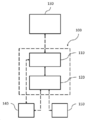
도 1은 여기에서 설명되는 하나 이상의 실시예들에 따라 해부학적 관절의 일부분의 손상 이미지를 생성하기 위한 시스템에 대한 개략도를 도시한다.
도 2는 여기에서 설명되는 하나 이상의 실시예들에 따라, 해부학적 관절의 일부분의 손상 이미지를 생성하기 위한 방법에 대한 순서도이다.
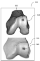
도 3은 여기에서 설명되는 하나 이상의 실시예들에 따라, 손상 이미지의 형태로 의사결정 지원 자료의 일례를 도시하며, 여기서 해부학적 관절에 대한 손상은 그래픽(graphics)을 사용하여 마킹된다.
도 4는 여기에서 사용되는 하나 이상의 실시예들에 따라, 해부학적 관절의 일부분의 손상 이미지를 생성하기 위한 방법에 대한 순서도이다.
도 5는 여기에서 사용되는 하나 이상의 실시예들에 따라, 다수의 손상 이미지들을 포함하는 손상 보고(report) 형태의 의사결정 지원 자료의 일례를 도시하며, 여기서 해부학적 관절에 대한 손상이 마킹되고/마킹되거나 적절한 임플란트의 유형 그리고 자리가 표시된다.
도 6는 여기에서 설명되는 하나 이상의 실시예들에 따라, 손상 이미지의 형태로 의사결정 지원 자료의 일례를 도시하며, 여기서 해부학적 관절에 대한 손상은 주석(annotation)을 사용하여 마킹된다.
도 7는 여기에서 설명되는 하나 이상의 실시예들에 따라, 의학적 이미지 데이터를 획득하는 단계부터, 손상 마킹 그리고 손상 마킹 이미지의 생성 단계를 포함하는, 해부학적 관절에 대한 결정된 손상을 수리하기 위한 임플란트 그리고/또는 가이드 툴을 설계하고 제조하는 단계를 예시하는 순서도이다.
본 발명의 실시예들 그리고 그 장점들은 다음의 상세한 설명을 참조함으로써 가장 잘 이해될 수 있다. 하나 이상의 도면들에 도시된 유사한 요소들을 식별하기 위해 동일한 참조 번호들이 사용된다는 것을 이해해야한다.Figure 1 shows a schematic diagram of a system for generating a damaged image of a portion of an anatomical joint in accordance with one or more embodiments described herein.
2 is a flowchart of a method for generating a damaged image of a portion of an anatomical joint, in accordance with one or more embodiments described herein.
Figure 3 illustrates an example of decision support data in the form of a corrupted image, in accordance with one or more embodiments described herein, wherein corruption to anatomical joints is marked using graphics.
4 is a flowchart of a method for generating a damaged image of a portion of an anatomical joint, in accordance with one or more embodiments used herein.
5 illustrates an example of decision support data in the form of a report comprising multiple damaged images, according to one or more embodiments used herein, wherein the damage to the anatomical joint is marked and / The type and place of the marking or appropriate implant is displayed.
Figure 6 illustrates an example of decision support data in the form of a corrupted image, in accordance with one or more embodiments described herein, wherein corruption to anatomical joints is marked using annotations.
FIG. 7 illustrates an implant for repairing a determined damage to an anatomical joint, including obtaining medical image data, creating a damaged marking and a damaged marking image, according to one or more embodiments described herein; and / ≪ / RTI > or guide tool.
Embodiments of the present invention and its advantages are best understood by reference to the following detailed description. It is to be understood that like reference numerals are used to identify like elements shown in one or more of the drawings.
도입부Introduction
본 발명은 일반적으로 환자의 해부학적 관절의 일부분에 대한 손상을 나타내는 의사결정 지원 자료를 생성하는 시스템 그리고 방법에 관한 것이다. 특히, 여기에 제시된 시스템 그리고 방법의 실시예는 환자의 해부학적 관절의 일부의 하나 이상의 손상 이미지를 생성함으로써 개선된 의사결정 지원 자료를 제공하며, 여기서 관절 또는 관절의 일부분에 대한 손상은 하나 이상의 손상 이미지들 중 적어도 하나에서 마킹된다. 즉, 환자의 관절에 대한 하나 이상의 시각화(visualization)가 해부학적 편차(anatomical deviations)의 표시(indications)/마킹(markings)/시각화와 함께 제공되며, 이는, 최적의 치료방법을 결정하는데 있어서 외과의사 또는 정형외과 담당자를 위한 의사결정 지원, 고객 또는 잠재 고객(손상된 관절의 상태에 대해 알림을 받고자 하는 환자를 위한 의사결정 지원 또는 예를 들어 묘사된 해부학적 관절에 대한 손상을 학습하는데 상업적 또는 학술적 관심이 있는 임의의 다른 사람)에 관한 평가를 하는 보험 대리인을 위한 의사결정 지원을 형성한다. 이는 예를 들어 환자의 치료에 대한 결정을 내리는 사람에게 의료 이미지 데이터로부터 얻어지는 더 많은 정보가 전달됨에 따라, 종래의 시스템 그리고 방법에 비해 큰 장점을 제공한다. 따라서, 이미지 데이터를 분석할 때 의료 전문가의 지식에 입각하여 의료 전문가가 수집하는 단편화된 정보만이 전달되기 때문에, 외과의사 또는 정형 외과 담당자에 의해 수신된 의사결정 지원 자료가 대다수 불충분해진다는 문제점들을 본 발명의 실시예들이 해결한다. 즉, 본 명세서에 제시된 실시예를 사용하여, 개선된 의사결정 지원 자료가 획득되며, 이는 의사결정 지원 자료에서 해부학적 관절이 묘사된 환자의 최적 치료가 이루어지기 위해 보다 많은 정보에 입각한 결정이 이루어지도록 한다. The present invention generally relates to a system and method for generating decision support data indicative of damage to a portion of a patient's anatomical joint. In particular, embodiments of the systems and methods described herein provide improved decision support data by generating one or more damaged images of a portion of an anatomical joint of a patient, wherein damage to the joint or a portion of the joint is caused by one or more injuries Are marked on at least one of the images. That is, one or more visualizations of the patient ' s joints are provided with indications / markings / visualization of anatomical deviations, which may be used by surgeons Or decision support for orthopedic surgeons, customer or prospective customers (decision support for patients who want to be informed about the condition of the injured joint, or commercial or academic interest in learning damage to the depicted anatomical joint, for example) Or any other person with a disability). This provides significant advantages over conventional systems and methods, for example, as more information from the medical image data is communicated to the person making the decision for treatment of the patient. Thus, when analyzing image data, only the fragmented information collected by the medical professionals based on the knowledge of the medical practitioner is transmitted, so that the majority of the decision support data received by the surgeon or orthopedic surgeon becomes insufficient Embodiments of the present invention are solved. That is, using the embodiments presented herein, improved decision support data is obtained, which allows more informed decisions to be made to optimally treat patients with anatomical joints depicted in the decision support data .
일부 실시예에서, 해부학적 관절은 무릎이지만 여기에 제시되는 방법 그리고 시스템은 임의의 적합한 해부학적 관절(예를 들어, 발목, 둔부, 발가락, 팔꿈치, 어깨, 손가락 또는 손목)의 손상 영상을 유도하는데 사용될 수도 있다. 무릎 관절의 대퇴부와 같이 관절의 일부분만 관심 대상이 되는 경우가 종종 있기 때문에, 이러한 경우 전체적인 해부학적 관절에 대한 손상이 결정될 필요는 없다. In some embodiments, the anatomical joint is a knee, but the method and system presented herein may lead to an injury image of any suitable anatomical joint (e.g., ankle, buttock, toe, elbow, shoulder, finger or wrist) . Since only a portion of the joint, such as the femur of the knee, is often of interest, the overall anatomic joint damage need not be determined in this case.
비-제한적인 예에서, 해부학적 관절은 무릎이고, 손상 이미지에서 결정되고 그리고 표시된(indicated)/마킹된(marked)/시각화된(visualized) 손상/해부학적 편차는 연골 그리고/또는 골연골(osteochondral) 병변(lesions)과 같은 무릎 관절의 대퇴부와 관련된다. 다른 비-제한적인 예에서, 해부학적 관절은 발목이며, 손상 이미지에서 결정되고 그리고 표시된/마킹된/시각화된 손상/해부학적 편차는 거골(talus)과 관련되어있다.In a non-limiting example, the anatomical joint is a knee, and the damage / anatomical deviation determined and marked / marked / visualized in the injured image indicates that the cartilage and / or osteochondral ) Lesions associated with the femur of the knee joint. In another non-limiting example, the anatomical joint is an ankle, determined in a damaged image, and displayed / marked / visualized impairment / anatomical deviation associated with the talus.
손상 영상은 생성된 해부학적 관절에 대해 생성된 3D 모델의 2D 표현으로부터의 영상 데이터를 포함 할 수 있고 그리고/또는 디지털 영상으로부터 직접 검색되는 2D 영상 데이터를 포함할 수 있으며, 의학(DICOM) 파일 또는 다른 적합한 이미지 파일 형식으로 통신할 수 있다. 3D 모델은 예를 들어 해부학적 관절 또는 그 일부의 상이한 층을 통해 방사선 이미지들을 스캐닝하는 과정 동안 캡쳐된 일련의 방사선 이미지에 기초하여 생성될 수도 있으며, 상기 스캐닝하는 과정은 방사선 이미지에 기초한 이미지 분할 과정(image segmentation process)에서 해부학적 관절 또는 그 일부분의 3D 이미지 표현을 생성하는데 필요한 모든 방사선 이미지 데이터를 캡처한다. 3D 모델은 뼈, 연골 그리고 다른 조직의 손상을 시각화하는데 유리하다. DICOM 형식 또는 이와 유사한 이미지 파일 형식은 해부학적 관절의 상이한 부분들을 시각화하는데 유리하다.The impaired image may include image data from a 2D representation of the 3D model generated for the generated anatomical joint and / or may contain 2D image data that is retrieved directly from the digital image, and may include a medical (DICOM) file or Other suitable image file formats can be communicated. The 3D model may be generated based on a series of radiographic images captured during the process of scanning the radiographic images, for example, through different layers of the anatomical joint or a portion of the same, wherein the scanning process includes an image segmentation process captures all radiographic image data needed to generate a 3D image representation of the anatomical joint or a portion thereof in an image segmentation process. 3D models are useful for visualizing damage to bones, cartilage, and other tissues. The DICOM format or similar image file format is advantageous for visualizing different parts of anatomical joints.
예를 들어, 3D 모델은, 연골, 힘줄 그리고/또는 인대와 같은 뼈 그리고 조직을 시각화하고 그리고 대퇴골 무릎 뼈 및 연골, 또는 조사되는 임의의 다른 관련 해부학적 관절의 뼈 및 연골과 관련된 손상을 시각화하는데 사용될 수 있다. 다른 예를 들어, DICOM 포맷 또는 이와 유사한 이미지 파일 포맷은 대퇴골 그리고 송골면 영역과 같은 무릎의 상이한 부분, 또는 조사되는 임의의 다른 관련 해부학적 관절의 상이한 부분(예를 들어, 발목의 거골과 같은 부분)을 시각화하기 위해 사용될 수 있다.For example, 3D models visualize bones and tissues such as cartilage, tendons, and / or ligaments and visualize injuries associated with bone and cartilage of the femur knee and cartilage, or any other related anatomical joints being examined Can be used. As another example, the DICOM format or similar image file format may be used for different parts of the knee, such as the femur and bony area, or any other part of the associated anatomical joint being irradiated (e.g., ). ≪ / RTI >
외과 의사 또는 정형 외과 실무자가 올바른 진단을 내리고 환자의 최적 치료를 결정할 수 있도록 의사결정 지원 자료를 형성하는 손상 평가 보고서에 하나 이상의 손상 이미지가 포함될 수도 있다. 하나 이상의 손상 이미지 또는 하나 이상의 손상 이미지가 포함된 손상 평가 보고서에는 어떠한 진단도 포함되어 있지 않다. 대신 이는 올바른 진단을 내리고 환자의 최적 치료를 결정하기 위한 의사결정 지원을 형성한다. 하나 이상의 손상 이미지를 포함하는 의사결정 지원 자료 또는 하나 이상의 손상 영상을 포함하는 손상 평가 보고서는 예를 들어 관절경 검사(arthroscopist)자가 보고자하는 것을 시각적으로 이해하는데에 도움을 주기 위해 관절경 검사 전에 사용될 표준 관절경 검사(arthroscopic)의 디지털 버전인 사전 관절경 툴(tool)로 사용될 수 있다. 이러한 방식으로 환자를 관절경 검사하지 않고도 충분한 정보가 수집 될수 있기 때문에 의사결정 지원 자료는 관절경 검사의 대안으로 사용될 수도 있다. 의사결정 지원 자료는 관절 성형술, 미세 파절의 모자이크 성형술과 같은 생물학적 치료 또는 금속 임플란트가 필요한 경우와 같이 바람직한 치료 계획을 세우는데 사용될 수 있다. One or more impairment images may be included in a damage assessment report that forms decision support materials that enable the surgeon or orthopedic practitioner to make the correct diagnosis and determine the optimal treatment for the patient. The damage assessment report, which contains more than one damaged image or more than one damaged image, does not include any diagnosis. Instead, it forms a good diagnosis and decision support to determine the optimal treatment of the patient. Decision support reports that include one or more impairment images or impairment assessment reports that include one or more impairments may be used, for example, to help visualize what the arthroscopist is seeing It can be used as an arthroscopic tool, a digital version of arthroscopic. Decision support materials may be used as an alternative to arthroscopy because sufficient information can be collected without arthroscopic examination of the patient in this manner. Decision support materials can be used to create a desired treatment plan, such as arthroplasty, biological treatment such as mosaicplasty with microfractures, or when metal implants are needed.
다른 예시로, 다른 유형의 사용자는 다른 목적으로 의사결정 지원 자료를 수신하여 사용할 수 있다. 하나 이상의 손상 이미지 형태 또는 하나 이상의 손상 이미지가 포함된 손상 평가 보고서 형태의 의사결정 지원 자료는 다른 상황에서의 의료 직원, 고객 또는 잠재 고객(손상된 관절의 상태에 대해 알기를 원하는 환자 또는 예를 들어 묘사된 해부학적 관절의 손상에 대해 학습하는데 상업적 또는 학술적 관심을 갖는 사람)에게 흥미로울 수 있다. 다른 실시예에서, 손상 이미지 또는 손상 평가 보고서는 인쇄된 형태 또는 디지털 형태로 표현될 수 있다. 디지털 형태의 손상 이미지 또는 손상 평가 보고서에 포함된 하나 이상의 손상 이미지는, 정적인 형식이거나 또는 처리 장치의 디스플레이에서 손상 이미지를 보는 사용자가 처리 장치에 연결된 입력 장치를 사용하여 제어 신호를 제공해줌으로써 이미지를 조작할 수 있는 형식 일 수 있다. 입력 장치는 예를 들어 키보드, 컴퓨터 마우스, 버튼, 터치 기능, 조이스틱, 또는 임의의 다른 적절한 입력 장치를 포함 할 수 있다. 일부 실시예에서, 의사결정 지원 자료는 결정된 뼈 그리고/또는 연골 손상에 대한 적절한 임플란트의 추천 그리고/또는 위치 표시를 더 포함 할 수 있다. 이와 관련하여, 적절한 임플란트는 결정된 손상과 일치하는 유형 그리고 치수를 갖는 임플란트를 의미하며, 이에 따라 결정된 손상을 수리하는데 적합하게 한다. 이러한 적절한 임플란트는 손상 이미지 또는 손상 보고에서 추가적으로 시각화될 수 있다.As another example, other types of users may receive and use decision support materials for other purposes. Decision support materials in the form of a damage assessment report that includes one or more damaged image types or one or more damaged images may be used by medical staff, customers, or potential customers in other situations, such as patients who want to know about the condition of a damaged joint, Or who have a commercial or academic interest in learning about the damage of anatomical joints). In another embodiment, the damaged image or damage assessment report may be expressed in printed or digital form. One or more damaged images in a digital form of corruption image or damage assessment report may be in a static format or may be provided by a user viewing the corrupted image on the display of the processing device by providing a control signal using an input device connected to the processing device, It can be in an operable format. The input device may include, for example, a keyboard, a computer mouse, a button, a touch function, a joystick, or any other suitable input device. In some embodiments, the decision support data may further include a recommendation and / or location indication of an appropriate implant for the determined bone and / or cartilage damage. In this regard, an appropriate implant implies an implant having a type and dimensions consistent with the determined damage, thereby making it suitable for repairing the determined damage. These appropriate implants can be further visualized in a damaged image or a damage report.
의사결정 지원 자료는, 일부 실시예에서, 적어도 하나의 골연골 자가이식 플러그에 적합한 이송 가이드 툴 그리고/또는 적절한 수확 그리고/또는 이식 위치를 나타내는 추천을 대신 포함할 수도 있다. 적절한 이송 가이드 툴 그리고/또는 적절한 수확 그리고 이식 위치는 손상 이미지 또는 손상 보고서에서 추가적으로 시각화될 수 있다. 일부 실시예에서, 의사결정 지원 자료는 그 자체로 관절에 손상을 주지 않는 해부학적 편차를 추가로 표시한다. 이러한 해부학적 편차는 결정된 손상에 대한 치료법의 선택에 영향을 줄 수 있다. 비-제한적인 예를 들어서, 심각한 골괴사 문제는 임플란트가 상황을 개선시키지 못할 수도 있는 다른 문제를 나타낼 수도 있다.The decision support material may, in some embodiments, instead include a transfer guide tool suitable for at least one osteochondroplasty implant plug and / or a recommendation indicating an appropriate harvest and / or implant location. Appropriate transfer guide tools and / or appropriate harvesting and implant locations may be additionally visualized in the damage image or damage report. In some embodiments, the decision support material further marks anatomical deviations that do not damage the joints themselves. These anatomical deviations can affect the choice of treatment for the determined injury. By way of non-limiting example, a severe osteonecrosis problem may indicate other problems in which the implant may not improve the situation.
프로세서는 일부 실시예들에서 청구된 기능들을 함께 수행하는 몇몇 상이한 프로세서들을 포함할 수 있다. 동일한 방식으로, 저장 매체는 일부 실시예에서 청구된 기능을 함께 수행하는 여러 가지 다른 저장 매체를 포함할 수 있다.A processor may include several different processors that together perform the claimed functions in some embodiments. In the same manner, the storage medium may include various other storage media that together perform the claimed functions in some embodiments.
개시된 해결책의 시스템 그리고 방법 실시예가 도면과 관련하여 보다 상세히 제시된다.DETAILED DESCRIPTION OF THE PREFERRED EMBODIMENTS A system and method embodiment of the disclosed solution is presented in more detail in connection with the drawings.
시스템 구조System structure
도 1은 하나 이상의 손상 이미지를 포함하는 환자의 해부학적 관절의 일부에 손상을 나타내는 의사결정 지원 자료를 생성하기 위한 시스템(100)의 개략도를 도시한다. 실시예들에 따르면, 시스템은 이미지 데이터 그리고 파라미터들을 수신 그리고 저장하도록 구성된 저장 매체(110)를 포함한다. 일부 실시예에서, 시스템(100)은 도 1의 점선 화살표로 나타낸 바와 같이 이미징 시스템(130)에 통신 가능하게 결합된다. 이미징 시스템(130)은 예를 들어 X선 이미지, 초음파 이미지, 컴퓨터 단층 촬영 (CT) 이미지, 양전자 방출 단층 촬영 (PET) 이미지 그리고 핵 자기공명 이미지 (MRI)와 같은 방사선 영상을 캡처하거나 생성하도록 구성될 수도 있다. 저장 매체(110)는 이미징 시스템(130)으로부터의 방사선 이미지 그리고/또는 방사선 이미지 데이터를 수신하여 저장하도록 구성될 수도 있다. Figure 1 shows a schematic diagram of a
시스템(100)은 이미지 데이터에 기초하여 해부학적 관절의 손상을 결정하고, 해부학적 관절의 결정된 손상이 마킹되는 해부학적 관절 또는 관절의 일부분의 손상 이미지 또는 관찰자가 손상을 인지할 수 있게 다른 방법으로 시각화되어 만들어진 손상 이미지를 생성하도록 구성된 프로세서(120)를 더 포함한다. 프로세서(120)는 예를 들어 범용 데이터 프로세서, 또는 다양한 프로세싱 동작을 수행하기 위한 명령을 실행할 수 있는 다른 회로 또는 집적 회로 일 수 있다.The
하나 이상의 실시예에서, 상기 프로세서는: 저장 매체로부터 해부학적 관절의 일부의 일련의 방사선 이미지를 수신하고; 상기 방사선 이미지에 기초하여 이미지 분할 프로세스에서 3차원 이미지 표현을 생성함으로써 그리고/또는 상기 생성된 저장 매체로부터 상기 생성된 3차원 이미지 표현을 수신함으로써, 일련의 방사선 이미지에 기초하는 해부학적 관절의 일부분의 3차원 이미지 표현을 획득하고; 이미지 분석을 사용하여 일련의 방사선 이미지들 그리고/또는 3차원 이미지 표현 중 적어도 하나에서 연골, 힘줄 그리고/또는 인대를 포함하는 해부학적 관절의 조직 부분들을 식별하고; 상기 방사선 이미지 그리고/또는 해부학적 관절 또는 그 일부의 3차원 이미지 표현을 분석함으로써 해부학적 관절에 대한 손상을 결정하도록 구성될 수 있다. 상기 프로세서(120)는 식별된 조직 부분들을 사용하고 그리고 이하의 이미지 분석 그리고 처리 동작들의 선택을 수행하도록 구성될 수도 있으며, 상기 이미지 분석 그리고 처리 동작들은:In at least one embodiment, the processor is configured to: receive a series of radiological images of a portion of an anatomical joint from a storage medium; By generating a three-dimensional image representation in the image segmentation process based on the radiological image and / or by receiving the generated three-dimensional image representation from the generated storage medium, a portion of the anatomical joint based on the series of radiological images Obtaining a three-dimensional image representation; Using image analysis to identify tissue portions of anatomical joints including cartilage, tendons and / or ligaments in at least one of a series of radiographic images and / or a three-dimensional image representation; And may be configured to determine damage to the anatomical joints by analyzing the radiological image and / or the three-dimensional image representation of the anatomical joint or a portion thereof. The
- 해부학적 관절의 적어도 하나의 조직 부분의 윤곽의 불규칙한 형상을 검출하는 동작; - detecting an irregular shape of the contour of at least one tissue portion of the anatomical joint;
- 해부학적 관절의 뼈 그리고/또는 연골 부분 내의 또는 인접한 영역의 강도가 소정값보다 높거나 낮은지를 검출하는 동작; 그리고/또는- detecting whether the intensity of the bone and / or the region within or adjacent to the cartilage portion of the anatomical joint is higher or lower than a predetermined value; And / or
- 해부학적 관절에 대한 소정의 손상 패턴을 나타내는 템플릿과 적어도 하나의 식별된 조직 부분을 비교하는 동작;Comparing the at least one identified tissue portion with a template representing a predetermined pattern of damage to the anatomical joint;
을 포함할 수 있다.. ≪ / RTI >
프로세서(120)는 해부학적 관절 또는 그 일부의 획득된 3차원 이미지 표현에서 해부학적 관절에 손상을 마킹하도록 추가로 구성되고; 의사결정 지원 자료를 생성하도록 추가로 구성되며, 여기서 의사결정 지원 자료의 하나 이상의 손상 이미지 중 적어도 하나에 해부학적 관절에 대한 결정된 손상이 마킹되며 그리고 손상 이미지 중 적어도 하나는 획득한 해부학적 관절 또는 그 일부의 3차원 이미지에 기초하여 생성된다.The
일부 실시예에서, 입력 방사선 이미지/의료 이미지 데이터에서 묘사된 관절의 뼈 그리고 연골을 식별하고 분석하는 것이 유리할 수 있는데, 이는 이들의 조합이 추가 정보를 제공할 수 있기 때문이며, 하지만 여기에 기술된 모든 실시예는 또한 묘사된 관절의 다른 조직이 식별되고 분석될 때 수행될 수 있다. In some embodiments, it may be advantageous to identify and analyze the bones and cartilage of the joints depicted in the input radiographic image / medical image data, as these combinations may provide additional information, but all of the features described herein Embodiments may also be performed when other tissues of the depicted joint are identified and analyzed.
하나 이상의 실시예에서, 프로세서(120)는 방사선 이미지 내의 모서리 또는 윤곽과 같은 경조 영역을 검출함으로써 방사선 이미지 내의 관절의 뼈 부분 그리고/또는 연골 부분을 식별하도록 구성될 수 있다. 프로세서(120)는 검출된 모서리 또는 윤곽을 비교하고, 그리고/또는 강도 레벨 또는 패턴을 소정의 템플릿과 비교함으로써 방사선 이미지에서 뼈 그리고/또는 연골과 같은 구조물들 식별하도록 구성될 수 있다.In one or more embodiments, the
위에 상술 한 바와 같이, 하나 이상의 실시예에서, 프로세서(120)는 이미지 분석 그리고 처리 동작의 선택을 수행함으로써 손상이 존재하는 것으로 판정하는 단계에서, 해부학적 관절의 연골 부분 그리고/또는 뼈 부분 내의 또는 인접한 영역의 강도가 소정의 임계치보다 높거나 낮은 것을 검출하도록 구성될 수 있다. 분석된 의료 이미지 데이터를 캡처한 이미지 영상 장치의 설정에 따라, 분석된 영상은 예를 들어 피질골, 유체/액체, 연골, 지방/골수 그리고 반월상 연골과 같은 상이한 강도 레벨을 갖는 물질을 나타낼 수 있다. 예를 들어, 건강한 관절이 유체가 없어야 하는 곳에서 유체가 감지되면 손상의 징조이다. 연골에 비정상 옆으로 유체가 검출된 경우, 이는 손상에 대한 표시가 될 수도 있다.As discussed above, in one or more embodiments, the
분석된 이미지의 상이한 강도의 레벨은 상이한 신호 강도 레벨에 해당하며, 이들은 일반적으로 0에서 1까지의 범위의 픽셀/복셀(voxel) 값 또는 흰색에서 검은색 까지의 그레이스케일(grey scale)로 도시되는 시각적 표현으로 나타내질 수 있다. 픽셀/복셀 값이 0에서 1까지의 범위인 실시예에서, 소정의 임계값은 0 과 1 사이의 적절한 값으로, 또는 적절한 그레이스케일 값으로 설정된다. 하나 이상의 실시예에서, 프로세서(120)는 추가적으로로 또는 대안적으로, 이미지 분석 그리고 처리 동작의 선택을 수행하는 단계에서, 해부학적 관절에서 적어도 하나의 조직 부분의 불규칙한 형상을 검출하고 그리고 해부학적 관절의 손상 여부를 결정하도록 구성된다. 하나 이상의 실시예에서, 프로세서(120)는 추가적으로 또는 대안적으로, 이미지 분석 그리고 프로세싱 동작의 선택을 수행하는 단계에서, 손상 이미지 내의 식별된 조직 부분과 소정의 해부학적 관절의 손상 패턴을 나타내는 템플릿과의 비교를 수행하도록 구성될 수 있다. 일부 실시예들에서, 이러한 결정은 해부학적 관절에 대한 소정의 손상 패턴을 나타내는 템플릿과 윤곽에 대한 검출된 불규칙한 형상을 비교하는 단계 그리고/또는 특정 영역에 대해 검출된 강도를 해부학적 관절에 대한 소정의 손상 패턴을 나타내는 템플릿과 비교하는 단계를 포함할 수 있다. 하나 이상의 실시예에서, 프로세서(120)는 의사결정 지원 자료의 하나 이상의 손상 이미지들 중 적어도 하나에 해부학적 관절에 대해 결정된 손상을 마킹, 시각화 또는 다른 방식으로 나타내도록 구성될 수 있다. 결정된 손상을 마킹, 시각화 또는 표시하기 위해, 프로세서(120)는 결정된 손상에 속하는 것으로 식별된 하나 이상의 픽셀/복셀의 또는 관련된 주위의 픽셀/복셀의 픽셀/복셀 값을 변경하도록 구성될 수 있어서, 다음의 동작들에 대한 선택(들)을 수행함으로써 결정된 손상은 시각적으로 구별되고 사용자/시청자에게 주목될 수 있게 되며, 상기 동작들은:The levels of the different intensities of the analyzed image correspond to different signal intensity levels, which are typically shown as a pixel / voxel value ranging from 0 to 1 or a gray scale from white to black It can be expressed in visual representation. In embodiments where the pixel / voxel values range from 0 to 1, the predetermined threshold is set to an appropriate value between 0 and 1, or to an appropriate grayscale value. In one or more embodiments, the
- 결정된 손상에 위치한 것으로 식별된 하나 이상의 픽셀/복셀의 휘도/강도 값을 변경하는 동작; 결정된 손상에 위치한 것으로 식별된 하나 이상의 픽셀/복셀의 하나 이상의 색차(chrominance)/색상 값을 변경하는 동작; 결정된 손상을 둘러싸는 것으로 식별된 하나 이상의 픽셀/복셀의 휘도/강도 값을 변경하는 동작;- changing the brightness / intensity value of one or more pixels / voxels identified as being located in the determined damage; Changing one or more chrominance / color values of one or more pixels / voxels identified as located in the determined damage; Changing the brightness / intensity value of one or more pixels / voxels identified as surrounding the determined damage;
- 결정된 손상을 둘러싸는 것으로 식별된 하나 이상의 픽셀/복셀의 하나 이상의 색차/색상 값을 변경하는 동작; 그리고/또는 결정된 손상 위치 또는 그 주위에 위치하는 것으로 식별된 하나 이상의 픽셀/복셀과 관련하여 이미지에 주석, 기호 또는 다른 손상 표시를 부가하는 동작;- changing one or more color difference / color values of one or more pixels / voxels identified as surrounding the determined damage; And / or adding annotations, symbols or other damage indications to the image in relation to at least one pixel / voxel identified as being located at or around the determined damage location;
을 포함할 수 있다.. ≪ / RTI >
하나 이상의 실시예에서, 프로세서(120)는 해부학적 관절 또는 그 일부로부터 획득한 3차원 이미지 표현에서 해부학적 관절에 손상을 마킹하도록 구성될 수 있다. 손상을 마킹하기 위해, 프로세서(120)는 이하의 동작들 중 하나 이상을 선택하여 수행함으로써, 시각적으로 구별되고 사용자/시청자에게 주목되는 결정된 손상에 속하는 것으로 식별된 복셀 위치 또는 이와 관련하여 하나 이상의 복셀의 복셀 값을 변경하도록 구성될 수 있으며, 상기 동작들은:In one or more embodiments, the
- 결정된 손상에 위치한 것으로 식별된 하나 이상의 복셀의 휘도/강도 값을 변경하는 동작; 결정된 손상에 위치한 것으로 식별된 하나 이상의 복셀의 하나 이상의 색차/색상 값을 변경하는 동작; 결정된 손상을 둘러싼 것으로 식별된 하나 이상의 복셀의 휘도/강도 값을 변경하는 동작;- changing the luminance / intensity value of one or more voxels identified as being located in the determined damage; Changing one or more color difference / color values of the one or more voxels identified as being located in the determined damage; Modifying the luminance / intensity value of the one or more voxels identified as surrounding the determined damage;
- 결정된 손상을 둘러싸는 것으로 식별된 하나 이상의 복셀의 하나 이상의 색차/색상 값을 변경하는 동작; 그리고/또는 결정된 손상 상에 또는 그 주위에 위치하는 것으로 식별된 하나 이상의 복셀과 관련하여 이미지에 주석, 기호 또는 다른 손상 표시를 부가하는 동작;- changing one or more color difference / color values of one or more voxels identified as surrounding the determined damage; Adding an annotation, symbol or other indication of damage to the image in relation to one or more voxels identified as being located on or around the determined damage;
을 포함할 수 있다.. ≪ / RTI >
하나 이상의 실시예에서, 프로세서는 일련의 방사선 이미지들과 3차원(3D) 이미지 표현을 동기화하거나 연관시키도록 구성될 수 있어서, 이미지들 중 하나에서 만들어진 마킹이 실시간으로 다른 이미지에 동일하게 나타난다. 동일 위치(same position)는 이후에 묘사되는 해부학적 관절의 동일한 위치 또는 동일한 위치영역으로 해석된다. 방사선 이미지 데이터에 기초하여 3D 이미지 표현이 생성되기 때문에, 방사선 이미지 데이터를 3D 표현으로 분할하는 동안 프로세서에 의해 2D 방사선 이미지 데이터와 3D 표시 사이의 동기화 또는 연결이 기술분야에서 알려진 방식으로 자동 수행될 수 있다. In one or more embodiments, the processor may be configured to synchronize or associate a three-dimensional (3D) image representation with a series of radiological images, such that markings made on one of the images appear equally to other images in real time. The same position is interpreted as the same position or the same positional region of the anatomical joint described later. Since the 3D image representation is generated based on the radiation image data, synchronization or connection between the 2D radiation image data and the 3D representation by the processor during the splitting of the radiation image data into the 3D representation can be performed automatically in a manner known in the art have.
일련의 방사선 이미지는 예를 들어 해부학적 관절 또는 그 일부의 상이한 층을 통해 방사선 이미지를 스캔하는 프로세스 동안에 캡쳐되며, 상기 프로세스는 방사선 이미지에 기초하여 이미지 분할 프로세스에서 해부학적 관절 또는 그 일부의 3차원 이미지 표현을 생성하는데 필요한 모든 방사선 이미지 데이터를 캡쳐한다. 일부 실시예에서, 손상은 해부학적 관절의 뼈 부분과 연골 부분 모두에 대해 결정될 수 있다. 대안적으로, 애플리케이션(application)에 따라 뼈 부분만 손상되거나 연골 부분이 손상되거나 혹은 다른 조직 부분이 손상될 수 있다. 일부 실시예에서, 해부학적 관절은 무릎이다. 다른 실시예에서, 해부학적 관절은 발목, 둔부, 발가락, 팔꿈치, 어깨, 손가락, 또는 손목과 같은 이미지 데이터 분석을 이용한 손상 결정에 적합한 임의의 다른 해부학적 관절일 수 있다. A series of radiological images are captured during a process of scanning a radiological image through a different layer of, for example, an anatomical joint or a portion thereof, and the process may be performed in a three-dimensional Captures all radiation image data needed to generate an image representation. In some embodiments, the damage may be determined for both the bone and cartilage portions of the anatomical joint. Alternatively, depending on the application, only the bone portion may be damaged, the cartilage portion may be damaged, or other tissue portions may be damaged. In some embodiments, the anatomical joint is a knee. In other embodiments, the anatomical joint may be any other anatomical joint suitable for determining damage using image data analysis such as ankle, buttock, toe, elbow, shoulder, finger, or wrist.
하나 이상의 실시예에서, 프로세서는 사전정의된 치료 세트로부터 적절한 치료를 선택하도록 구성될 수도 있다. 상기 선택은 해부학적 관절 또는 그 일부의 3차원 이미지 표현 및/또는 방사선 이미지로부터의 데이터에 기반할 수 있다.In one or more embodiments, the processor may be configured to select an appropriate treatment from a predefined treatment set. The selection may be based on a three-dimensional image representation of the anatomical joint or a portion thereof and / or data from the radiological image.
일부 실시예에서, 상기 프로세서는 가변 치수를 갖는 사전정의된 임플란트 세트로부터 적절한 임플란트를 선택하도록 구성될 수 있다. 이와 관련하여, 적절한 임플란트란 결정된 손상과 대응되는 유형 및 치수를 갖는 임플란트를 의미하며, 이에 따라 결정된 손상을 복원하는 것을 적합하게 한다. 하나 이상의 실시예들에서, 프로세서는 하나 이상의 손상 이미지들 중에서 선택된 임플란트를 시각화하도록 구성될 수 있다.In some embodiments, the processor may be configured to select an appropriate implant from a predefined set of implants having variable dimensions. In this regard, an appropriate implant refers to an implant having the type and dimensions corresponding to the determined damage, thereby making it appropriate to restore the determined damage. In one or more embodiments, the processor may be configured to visualize an implant selected from one or more impaired images.
일부 실시예에서, 프로세서는 적어도 하나의 골연골 자가이식 플러그에 적합한 크기 및/또는 적절한 수확 및/또는 임플란트 위치를 포함할 수 있는 골연골 자가이식을 위한 이송 가이드 툴을 제안하도록 구성될 수 있다. 이와 관련하여, 적절한 수확 위치는 결정을 내린 손상을 수리하기 위해 환자에게서 적절한 자가이식 플러그가 수확될 수 있는 위치를 의미한다. In some embodiments, the processor may be configured to propose a delivery guide tool for osteochondral bone implantation, which may include a size and / or an appropriate harvest and / or implant location suitable for at least one osteochondral autograft plug. In this regard, a suitable harvest location refers to a location where a self-implanting plug suitable for the patient can be harvested to repair the underlying damage.
일부 실시예에서, 의사결정 지원 자료는 의료진, 예를 들어 외과 의사 또는 정형외과 의사에 의해 사용되도록 적응된다. 의사결정 지원 자료에는 결정된 손상의 일부를 치료하기 위한 적절한 치료에 대한 권장사항이 포함될 수 있다.In some embodiments, the decision support material is adapted to be used by a medical staff, for example a surgeon or an orthopedic surgeon. Decision support materials may include recommendations for appropriate treatment to treat some of the determined injuries.
대안적으로, 의사결정 지원 자료는 골연골 자가이식으로 결정된 손상의 일부를 복구하기 위한 하나 이상의 전달 가이드 툴의 적절한 설계에 대한 권장사항을 포함한다. 의사결정 지원 자료에는 이러한 경우 골연골 자가이식 플러그에 적합한 수확 장소에 대한 권장사항이 포함될 수 있다. 이러한 적절한 수확 장소 및/또는 이송 가이드 툴은 손상 이미지 또는 손상 보고에서 추가적으로 시각화될 수 있다.Alternatively, the decision support material includes recommendations for the proper design of one or more delivery guide tools to restore some of the damage determined by the osteochondral autograft. Decision support materials may include recommendations for harvest sites suitable for osteochondral autograft plugs in this case. Such suitable harvesting locations and / or transport guide tools may additionally be visualized in the damaged image or damage report.
일부 실시예에서, 손상 이미지는 고객 또는 잠재고객(잠재고객으로는 예를 들어 손상된 관절의 상태에 대해 알고 싶어하는 환자 또는 예를 들어 묘사된 해부학적 관절의 손상에 대해 학습하는데 상업적 또는 학술적 관심을 갖는 사람이 포함될 수 있음)에 관한 평가를 하는 보험 에이전트에 의해 사용되도록 적응된 의사결정 지원 자료의 일부이다. 의사결정 지원 자료는 인쇄된 보고서의 형태일 수 있거나, 예를 들어 태블릿 컴퓨터 또는 스마트폰 상에서 볼 수 있도록 적용된 하나 이상의 컴퓨터 파일의 형태일 수 있다. 의사결정 지원 자료가 하나 이상의 컴퓨터 파일 형식일 경우, 하나 이상의 손상 이미지는 일반 2D 이미지 형식이거나 해부학적 관절 또는 그 일부의 대화형(interactive) 3D 모델 형식일 수 있다.In some embodiments, the impaired image can be a customer or prospect (e.g., a potential customer has a commercial or academic interest in learning about the impairment of the anatomical joint, for example, a patient who wants to know about the condition of the damaged joint, (Which may include persons) that are part of the decision support materials adapted to be used by an insurance agent. The decision support material may be in the form of a printed report or in the form of one or more computer files adapted for viewing on, for example, a tablet computer or smart phone. If the decision support material is in one or more computer file formats, the one or more damaged images may be in the form of a generic 2D image or an interactive 3D model of anatomical joints or portions thereof.
하나 이상의 실시예에서, 시스템(100)은 예를 들어 손상 이미지 또는 하나 이상의 손상 이미지를 포함하는 손상 평가 보고(서)의 형태로 이미지 데이터를 디스플레이하도록 구성된 디스플레이부(140)를 선택하여 포함할 수 있다. 디스플레이부(140)는 프로세서(120) 또는 입력기(150)로부터 수신된 제어 신호에 응답하여 저장매체(110)로부터 직접적으로 디스플레이하기 위해 이미지 데이터를 검색하고 그리고/또는 프로세서(120)를 통해 디스플레이하기 위한 이미지 데이터를 수신하도록 구성될 수 있으며, 이에 대해서는 아래에서 더 자세히 설명한다.In one or more embodiments, the
일부 실시예에서, 시스템(100)은 사용자 입력을 수신하도록 구성된 하나 이상의 입력기(150)를 선택적으로 더 포함할 수 있다. 입력기(150)는 전형적으로 수신된 사용자 입력을 해석하고 수신된 사용자 입력에 응답하여 제어 신호를 생성하도록 구성된다. 디스플레이부(140) 및 입력기(150)는 시스템(100)에 통합되거나, 시스템(100)에 접속되거나, 또는 시스템(100)에 통신가능하게 연결될 수 있다. 상기 입력기(150)는 예를 들어 표시된 손상 이미지 또는 하나 이상의 손상 이미지를 포함하여 디스플레이되는 손상 평가 보고와 관련하여 입력되는 수신된 사용자 입력을 해석하고 수신된 사용자 입력에 응답하여 이미지의 디스플레이 또는 디스플레이되는 이미지 데이터의 조작을 트리거링(trigger)하기 위한 제어 신호를 생성하도록 구성될 수 있으며, 상기 조작은 일시적이거나 영구적일 수 있다. 상기 조작은 예를 들어 주석을 제공하거나, 이미지 또는 이미지의 일부를 이동시키거나 또는 변경하고, 시점(viewing perpective)을 변경하거나, 줌인 또는 줌아웃하고, 그리고/또는 사용자가 향상된 방식으로 디스플레이된 이미지를 보고 분석할 수 있게 하는 임의의 다른 적절한 조작 양태를 포함할 수 있다. 입력기(150)는 예를 들어 키보드, 컴퓨터 마우스, 하나 이상의 버튼, 터치 기능, 조이스틱 그리고/또는 임의의 다른 적절한 입력기의 선택을 포함할 수 있다. 일부 실시예에서, 프로세서(120)는 입력기(150)로부터 제어 신호를 수신하고, 수신된 제어 신호에 응답하여 디스플레이되고 있는 이미지 데이터, 즉 표시된 이미지를 조작하는 이미지 데이터를 처리하도록 구성될 수 있다. 프로세서(120)는 여기에 제시된 임의의 또는 모든 실시예의 방법 단계를 수행하도록 또한 구성될 수 있다.In some embodiments, the
방법 실시예들Method embodiments
도 2는 환자의 해부학적 관절의 일부에 손상을 나타내는 의사결정 지원 자료를 생성하기 위한 방법 실시예의 순서도로서, 여기서 의사결정 지원 자료는 하나 이상의 손상 이미지를 포함한다. 하나 이상의 실시예에 따르면, 상기 방법은:2 is a flow chart of a method embodiment for generating decision support data indicative of damage to a portion of an anatomical joint of a patient, wherein the decision support data comprises one or more impaired images. According to at least one embodiment, the method comprises:
단계(210): 환자의 해부학적 관절의 일련의 방사선 이미지를 수신한다.Step 210: receives a series of radiological images of the anatomical joint of the patient.
일부 실시예에서, 해부학적 관절은 무릎이다. 다른 실시예에서, 해부학적 관절은 발목, 둔부, 발가락, 팔꿈치, 어깨, 손가락 또는 손목과 같은 이미지 데이터 분석을 이용했을 때 손상을 판정하는데 적합한 임의의 다른 해부학적 관절일 수 있다.In some embodiments, the anatomical joint is a knee. In another embodiment, the anatomical joint may be any other anatomical joint suitable for determining damage using image data analysis such as ankle, buttock, toe, elbow, shoulder, finger or wrist.
단계(220): 저장 매체로부터 3차원 이미지 표현을 수신하거나 또는 방사선 이미지에 기초하여 이미지 분할 프로세스에서 3차원 이미지 표현을 생성함으로써 일련의 방사선 이미지에 기초하는 해부학적 관절의 3차원 이미지를 획득한다.Step 220: Obtain a three-dimensional image of the anatomical joint based on a series of radiological images by receiving a three-dimensional image representation from a storage medium or generating a three-dimensional image representation in an image segmentation process based on the radiological image.
단계(230): 이미지 분석을 사용하여, 일련의 방사선 이미지 중 적어도 하나에서, 연골, 힘줄 및/또는 인대를 포함하는 해부학적 관절의 조직 부분을 식별한다.Step 230: Using image analysis, identify tissue portions of anatomical joints, including cartilage, tendons, and / or ligaments, in at least one of a series of radiological images.
하나 이상의 실시예에서, 이미지 분석은, 방사선 이미지에서 모서리 또는 윤곽과 같은 경조 영역을 검출하는 단계, 및 사전정의된 템플릿과 상기 검출된 모서리 또는 윤곽을 비교하는 것을 통해 방사선 이미지에서 뼈 및/또는 연골과 같은 구조물들을 추가로 식별하는 단계에 의해 방사선 이미지에서 관절의 뼈 부분 및/또는 연골 부분을 식별한다.In one or more embodiments, the image analysis may comprise the steps of detecting a toned area such as a corner or contour in the radiological image, and comparing the detected edge or contour with a predefined template, To identify the bone and / or cartilage portion of the joint in the radiological image.
일부 실시예에서, 손상은 해부학적 관절의 뼈 부분과 연골 부분 모두에 대해 결정될 수도 있다.In some embodiments, the damage may be determined for both the bone portion and the cartilage portion of the anatomical joint.
입력 방사선 이미지/의료 이미지 데이터에서 묘사된 관절의 뼈 및 연골을 식별하고 분석하는 것은, 이들의 조합이 추가적인 정보를 제공할 수 있기 때문에 유리할 수 있지만, 여기에 기재된 모든 실시예들은 묘사되는 관절의 뼈 및 연골 또는 임의의 다른 조직과 같은 자료들 중 오직 하나만이 식별되고 분석되는 경우에도 수행될 수 있다.While identifying and analyzing the bones and cartilage of the joint described in the input radiographic image / medical image data may be advantageous since a combination of these may provide additional information, And only one of the materials such as cartilage or any other tissue is identified and analyzed.
단계(240): 해부학적 관절 또는 그 일부에 대한 3차원 이미지 표현 및/또는 방사선 이미지를 분석함으로써 해부학적 관절에 대한 손상을 결정한다. 다른 실시예에서, 단계(230)에서의 분석은 다음의 이미지 분석 및 이미지 처리 동작들 중 임의의 또는 모두에 대한 선택을 수행하는 단계를 포함할 수 있으며, 상기 동작들은:Step 240: Determine the damage to the anatomical joint by analyzing the three-dimensional image representation and / or the radiological image of the anatomical joint or a portion thereof. In another embodiment, the analysis at
- 해부학적 관절의 적어도 하나의 조직 부분의 윤곽의 불규칙한 형상을 검출하는 동작; 및/또는- detecting an irregular shape of the contour of at least one tissue portion of the anatomical joint; And / or
- 뼈 부분 및/또는 연골 부분 내의 또는 인접한 영역의 강도가 사전결정된 값보다 높거나 낮은지 검출하는 동작; 및/또는- detecting whether the intensity of the bone part and / or the area in or adjacent to the cartilage part is higher or lower than a predetermined value; And / or
- 해부학적 관절에 대한 소정의 손상 패턴을 나타내는 템플릿과 적어도 하나의 식별된 조직 부분을 비교하는 동작;Comparing the at least one identified tissue portion with a template representing a predetermined pattern of damage to the anatomical joint;
을 포함할 수 있다.. ≪ / RTI >
하나 이상의 실시예에서, 단계(240)의 방법은 해부학적 관절의 뼈 부분 및/또는 연골 부분 내의 또는 인접한 영역의 강도가 소정의 임계값보다 높거나 낮은지를 검출하는 단계를 포함할 수도 있다. 분석된 의료 이미지 데이터를 캡처한 이미지 장치의 설정에 따라 분석된 이미지는 예를 들어 피질골, 액체, 연골, 지방/골수 그리고 반월모양의 연골과 같이 서로 다른 강도 레벨을 가진 물질들을 나타낼 수 있다. In at least one embodiment, the method of
분석된 이미지의 서로 다른 강도 레벨은 서로 다른 신호 강도 레벨에 대응되며 일반적으로 0에서 1까지의 픽셀/복셀 값 또는 흰색에서 검은색 까지의 그레이스케일로 표시된 시각적 표현으로 나타낼 수 있다. 픽셀/복셀 값이 0에서 1까지의 범위인 실시예에서, 사전결정된 임계 값은 0과 1 사이의 적절한 값 또는 적절한 그레이스케일 값으로 설정된다.The different intensity levels of the analyzed image correspond to different signal intensity levels and can generally be represented by a pixel / voxel value from 0 to 1 or a visual representation in gray to scale from white to black. In embodiments where pixel / voxel values range from 0 to 1, the predetermined threshold is set to an appropriate value between 0 and 1 or an appropriate gray scale value.
하나 이상의 실시예에서, 단계(240)의 방법은 해부학적 관절의 하나의 조직 부분의 윤곽의 불규칙한 형상을 검출하고 이것이 해부학적 관절의 손상을 나타내는지 여부를 결정하는 단계를 추가로 또는 대안적으로 포함할 수 있다. 하나 이상의 실시예에서, 단계(240)의 방법은 해부학적 관절에 대한 소정의 손상 패턴을 나타내는 템플릿과 손상 이미지 내에서 식별된 조직 부분을 비교하는 단계를 추가로 또는 대안적으로 포함할 수 있다. 일부 실시예들에서, 이러한 결정은 해부학적 관절에 대한 소정의 손상패턴을 나타내는 템플릿과 윤곽의 검출된 불규칙한 형상을 비교하는 단계, 및/또는 특정 영역에 대해 검출된 강도를 해부학적 관절에 대한 소정의 손상 패턴을 나타내는 템플릿과 비교하는 단계를 포함할 수 있다.In at least one embodiment, the method of
단계(250)에서, 해부학적 관절 또는 이의 일부에 대해 획득한 3차원 이미지 표현에서 해부학적 관절에 대한 손상을 표시한다.At
단계(260)에서, 의사결정 지원 자료를 생성하며, 여기서 해부학적 관절에 대한 손상은 의사결정 지원 자료의 하나 이상의 손상 이미지 중 적어도 하나에서 마킹되며, 그리고 손상 이미지 중 적어도 하나는 해부학적 관절 또는 이의 일부에 대하여 획득된 3차원 이미지 표현에 기초하여 생성된다. 일부 실시예에서, 입력 방사선 이미지/의료 이미지 데이터에서 도시된 관절의 뼈와 연골 모두를 단계(230)에서 식별하고 단계(240)에서 분석하는 것이 유리할 수 있지만, 여기에 기재된 모든 실시예들은 뼈 또는 연골 또는 묘사된 관절의 임의의 다른 조직 부분 중 오직 하나의 물질만이 식별되고 분석되는 경우에서도 수행될 수 있다. At
하나 이상의 실시예에서, 단계들(250 및 260)의 마킹 방법은 마킹, 시각화 또는 해부학적 관절에 대한 결정된 손상을 표시하는 다른 방법을 포함한다. 결정된 손상을 마킹, 시각화 또는 표시하는 것은 결정된 손상에 속하는 것으로 식별된 픽셀/복셀과 관련되는 또는 이를 둘러싸는 하나 이상의 픽셀/복셀의 픽셀/복셀 값을 변경하여, 결정된 손상이 시각적으로 구별되고 사용자/뷰어(viewer)에게 주목되게 한다. 판정된 손상에 속하는 것으로 식별된 픽셀/복셀 상에 있거나, 이와 관련되거나 또는 그 주위에 있는 하나 이상의 픽셀/복셀의 픽셀/복셀 값의 이러한 변경은, 예를 들어 다음의 동작들에 대한 선택을 포함할 수 있으며, 상기 동작들은:In at least one embodiment, the marking method of
- 결정된 손상에 위치한 것으로 식별된 하나 이상의 픽셀/복셀의 휘도/강도 값을 변경하는 동작;- changing the brightness / intensity value of one or more pixels / voxels identified as being located in the determined damage;
- 결정된 손상에 위치한 것으로 식별된 하나 이상의 픽셀/복셀의 하나 이상의 색차/색상 값을 변경하는 동작;- changing one or more color difference / color values of one or more pixels / voxels identified as being located in the determined damage;
- 결정된 손상을 둘러싼 것으로 식별된 하나 이상의 픽셀/복셀의 휘도/강도 값을 변경하는 동작;- changing the brightness / intensity value of one or more pixels / voxels identified as surrounding the determined damage;
- 결정된 손상을 둘러싸는 것으로 식별된 하나 이상의 픽셀/복셀의 하나 이상의 색차/색상 값을 변경하는 동작; 및/또는- changing one or more color difference / color values of one or more pixels / voxels identified as surrounding the determined damage; And / or
- 결정된 손상 상에 또는 그 주위에 위치하는 것으로 식별된 하나 이상의 픽셀/복셀과 관련하여 이미지에 주석, 기호 또는 다른 손상 마크를 부가하는 동작;을 포함한다.- adding an annotation, symbol or other damage mark to the image in relation to one or more pixels / voxels identified as being located on or around the determined damage.
일부 실시예에서, 방사선 이미지와 3차원 이미지 표현은, 이미지들 중 하나에서 만들어진 마킹이 다른 이미지의 동일한 위치에 나타나도록 서로 연관되거나 혹은 동기화될 수 있다. 하나 이상의 이러한 실시예에 따르면, 단계들(250 및 260)의 방법은 방사선 이미지 및 3차원 이미지 표현을 연관시키거나 동기화시키는 단계를 포함할 수 있어, 이미지들 중 하나에서 만들어진 마킹이 다른 이미지의 동일한 위치에 나타나도록 한다.In some embodiments, the radiation image and the three-dimensional image representation may be correlated or synchronized such that markings made in one of the images appear at the same location in the other image. According to one or more such embodiments, the method of
도 3은 여기에 설명된 하나 이상의 실시예들에 따라, 손상 이미지 형태의 의사결정 지원 자료의 일례를 도시하며, 여기서 해부학적 관절에 대한 손상은 그래픽을 사용하여 마킹된다. 도 3에 도시된 비-제한적인 예에서, 손상 이미지 형태의 의사결정 지원 자료(300)는 해부학적 관절의 2개의 시각적 표현들(310,330)을 도시하고, 결정된 손상(320,340)은 식별된 결정된 손상에 위치한 그리고/또는 주위에 위치한 픽셀/복셀의 휘도/강도 레벨 및/또는 채도/채색 값을 변경하는 것으로 마킹/표시/시각화된다. 물론, 애플리케이션에 따라, 그리고 의사결정 지원 자료를 보는 사람이 결정된 손상을 보고 분석할 수 있게 하는 명확한 마킹, 시각화 또는 표시를 제공하는 것에 따라, 임의의 휘도/강도의 값 및/또는 채도/채색 값이 선택될 수 있다. 실시예들에서, 선택된 휘도/강도 값 및 채도/채색 값은, 이전 픽셀/복셀 값을 대체하거나 혹은 새로운 픽셀/복셀 값을 오래된 픽셀/복셀 값과 알파 블렌딩 팩터(alpha blending factor)와 같은 스케일링 계수(scaling factor)를 사용하여 블렌딩시킴으로써, 픽셀/복셀로 할당될 수 있다. 단일의 결정된 손상은 추가적으로, 각 픽셀이 나타내는 손상 유형에 따라 상이하게 할당된 픽셀/복셀 값을 사용하여 마킹되거나, 시각화되거나 또는 표시될 수 있다. 예를 들어, 손상을 마킹, 시각화 또는 표시하는 것은, 이하의 사항들에 대한 상이한 새로운 픽셀/복셀 값을 포함할 수 있다: Figure 3 illustrates an example of decision support data in the form of a damaged image, in accordance with one or more embodiments described herein, wherein damage to anatomical joints is marked using graphics. In the non-limiting example shown in FIG. 3, the
- 깊은 손상, 예를 들어 뼈에 이르기 까지의 연골 손상; - deep damage, for example cartilage damage to bone;
- 퇴행성 연골, 재생 연골/흉터 조직 또는 변형된 연골과 같은 부분적으로 깊은 손상;- Deep partial damage, such as degenerative cartilage, regenerated cartilage / scar tissue or deformed cartilage;
- 골수 병변(BML); 및 - bone marrow lesions (BML); And
- 뚜렷한 낭종.- A distinct cyst.
하나 이상의 손상 이미지 형태의 의사결정 지원 자료 또는 하나 이상의 손상 이미지를 포함하는 손상 보고의 예시가 도 5 및 도 6과 관련되어 추가로 논의될 것이다.An example of a corruption report including one or more corruption images in the form of decision support data or one or more corruption images will be further discussed with reference to FIGS. 5 and 6. FIG.
도 4는 해부학적 관절의 손상 이미지를 생성하기 위한 하나 이상의 방법 실시예의 순서도로서, 상기 손상 이미지 내에서는 관절에 대한 손상이 마킹되어 있고, 또한 이미지내에 결정된 손상을 수리하기 위한 적절한 임플란트의 추천을 포함시키는 선택적인 방법 단계를 더 포함한다. 도 4의 단계들(210-260)은 도 2의 동일한 단계들에 대응하고, 그리고 도 4의 방법 실시예는 이하의 추가 단계들을 더 포함한다.Figure 4 is a flow diagram of one or more method embodiments for generating an injured image of an anatomical joint in which the damage to the joint is marked and includes the recommendation of an appropriate implant to repair the damage determined within the image Lt; RTI ID = 0.0 > and / or < / RTI > The steps 210-260 of FIG. 4 correspond to the same steps of FIG. 2, and the method embodiment of FIG. 4 further includes the following additional steps.
단계(470)에서: 해부학적 관절 또는 그 일부의 3차원 이미지 표현 및 방사선 이미지로부터의 데이터에 기초하여 가변하는 치수를 갖는 사전정의된 임플란트 세트로부터 적절한 임플란트를 선택한다. At step 470: a suitable implant is selected from a predefined set of implants having varying dimensions based on the three-dimensional image representation of the anatomical joint or a portion thereof and the data from the radiological image.
이와 관련하여, 적절한 임플란트는 결정된 손상과 일치하는 유형 및 치수를 갖는 임플란트를 의미하며, 이에 따라 결정된 손상을 수리하는데 적합하게 한다.In this regard, an appropriate implant implies an implant having a type and dimensions consistent with the determined damage, thereby making it suitable for repairing the determined damage.
단계(480)에서: 하나 이상의 손상 이미지들 중 적어도 하나에서 선택된 임플란트를 시각화한다. 일부 실시예에서, 의사결정 지원 자료는 결정된 뼈 및/또는 연골 손상에 대한 적절한 임플란트의 추천 및/또는 위치 표시를 더 포함할 수 있다. 이러한 적절한 임플란트는 손상 이미지 또는 손상 보고에서 추가로 시각화될 수 있다. At step 480: visualize the selected implant in at least one of the one or more damaged images. In some embodiments, the decision support data may further include recommendations and / or location indications of appropriate implants for the determined bone and / or cartilage damage. These appropriate implants can be further visualized in a damaged image or a damage report.
선택된 임플란트가 손상 이미지 또는 손상 보고에서 어떻게 시각화될 수 있는 지에 대한 일례가, 다수의 손상 이미지들(510, 530, 560, 570)을 포함하는 손상 보고 형태의 의사결정 지원 자료(500)의 예를 도시하는 도 5 에 도시되며, 여기에서 설명된 하나 이상의 실시예에 따르면, 해부학적 관절에 대한 손상(520, 540)이 마킹되고/되거나 적절한 임플란트(550, 580)의 유형 및 배치가 표시되어 있다.One example of how a selected implant can be visualized in a corruption image or corruption report is an example of a corruption report type
손상 이미지의 일례는 골연골 자가이식을 시각화하기 위해 사용될 수 있다는 점이 도 8에 도시되어 있으며, 도 8은 여기에서 설명되는 하나 이상의 실시예들에 따라, 손상 이미지(810)의 일례를 도시하며, 여기서 골연골 자가이식을 위한 제안된 이송 가이드 툴의 배치가 820으로 표시된다.An example of an impaired image is shown in FIG. 8, which may be used to visualize an osteochondral autograft, and FIG. 8 illustrates an example of a damaged image 810, in accordance with one or more embodiments described herein, Here, the placement of the proposed transfer guide tool for osteochondral autograft is indicated by 820.
하나 이상의 실시예에서, 의사결정 지원 자료는 의료진, 예를 들어 외과 의사 또는 정형외과 의사에 의해 사용되도록 적응된다. 하나 이상의 실시예에서, 의사결정 지원 자료는, 의료진, 예를 들어 외과 의사 또는 정형외과 의사에 의해 사용되도록 적응되며 그리고 도 3과 관련하여 설명된 실시예들 중 임의의 것에 따라 적절한 임플란트에 대한 권고사항을 더 포함한다.In one or more embodiments, the decision support material is adapted to be used by a medical staff, such as a surgeon or orthopedic surgeon. In one or more embodiments, the decision support material may be adapted to be used by a medical staff member, e.g., a surgeon or orthopedic surgeon, and may be provided with recommendations for appropriate implants according to any of the embodiments described in connection with FIG. 3 .
일부 실시예에서, 의사결정 지원 자료는 고객 또는 잠재 고객(잠재 고객으로는 손상된 관절의 상태에 대해 알고 싶어하는 환자; 또는 예를 들어 묘사된 해부학적 관절의 손상에 대해 학습하는데 상업적 또는 학술적 관심을 갖는 사람)에 관한 평가를 하는 보험 에이전트에 의해 사용되도록 적응된다.In some embodiments, the decision support material may be a customer or prospect (a potential customer is a patient who wants to know about the condition of an injured joint, or, for example, has commercial or academic interest in learning about the damage of the anatomical joint depicted). Person) who is being evaluated by the insurance agent.
일부 실시예에서, 의사 결정 지원 자료는 환자의 해부학적 관절의 적어도 일부의 3D 시각화 또는 3D 모델을 나타내는 2D 및 3D 이미지, 관절에 대한 시각적 마킹/표시, 그리고 주석/해부학적 편차에 대한 서면 평가를 포함한다. 여기에 설명된 하나 이상의 실시예들에 따라, 도 6은 손상 이미지(600, 610)에 묘사된 해부학적 관절에 대한 손상이 주석(620)을 사용하여 마킹된/표시된/시각화된 2개의 손상 이미지(600,610)를 포함하는 의사결정 지원 자료의 일부의 예시를 도시한다. 도 6의 비-제한적인 예에서, 묘사된 해부학적 관절은 무릎이고, 주석(620)은 환자가 슬개골에 병변을 갖는다는 것을 나타낸다. 하나 이상의 실시예에서, 도 2 또는 도 4의 방법은 선택적으로 하나 이상의 손상 이미지의 형태로 의사결정 지원 자료의 시각적 표현, 또는 하나 이상의 손상 이미지를 포함하는 손상 평가 보고를 예를 들어 그래픽 사용자 인터페이스(GUI)에서 디스플레이하는 것이다. 도 3, 도 5 및 도 6의 비-제한적인 예들에 도시된 바와 같이, GUI에서 제공되는 시각적 표현은, 예를 들어 도 3의 손상 이미지(300)과 같이 해부학적 관절에 대한 손상이 마킹/시각화/표시되는 손상 이미지들을 포함할 수 있거나, 그리고/또는 도 4의 손상 보고(500)와 같은 추천 임플란트 또는 가이드 툴의 정확한 위치를 표시하는 관절의 3D 표현 및 2D 표현과 함께 손상 이미지들을 포함하는 손상 보고를 포함할 수 있거나, 그리고/또는 도 6에서의 의료 이미지들(600 및 610)으로 중요 의료 정보를 표시하도록 추가되는 주석(620)과 같은 주석들의 추가가 이루어진 의료 이미지 데이터를 포함할 수 있다. 상기 방법은 이들 실시예들 중 임의의 실시예에서 디스플레이를 위한 이미지 데이터를 수신하는 단계 및/또는 제어 신호를 수신하는 단계, 및 제어 신호에 응답하여 디스플레이하기 위해 이미지 데이터를 검색하는 단계를 포함할 수 있다. 하나 이상의 실시예에서, 디스플레이되는 손상 평가 보고 도는 손상 평가 보고 또는 의사결정 지원 자료의 다른 부분은 시스템이 디스플레이를 구성하거나 또는 디스플레이에 통합되거나, 접속되거나, 또는 디스플레이에 연결되거나, 또는 디스플레이에 결합된 하나 이상의 입력기를 사용하여 사용자에 의해 조작될 수 있다. 이들 실시예에 따르면, 도 2 또는 도 4의 방법은 입력기로부터 사용자 입력을 수신하고, 수신된 사용자 입력을 해석하고, 수신된 사용자 입력에 응답하여 하나 이상의 제어 신호를 생성하는 단계를 선택적으로 더 포함할 수 있다. 수신된 사용자 입력은 디스플레이된 손상 이미지 또는 하나 이상의 손상 이미지를 포함하는 디스플레이된 손상 평가 보고와 관련될 수 있고, 일시적으로 또는 영구적으로 디스플레이되고 있는 것을 조작하기 위해 상기 수신된 사용자 입력에 응답하여 제어 신호를 생성할 수 있다. 조작은 예를 들어 주석을 제공하거나, 이미지 또는 이미지의 일부를 이동 또는 변경하고, 시점을 변경하고, 줌인 또는 줌아웃하고, 그리고/또는 사용자가 개선된 방식으로 디스플레이된 이미지를 보고 분석할 수 있게 하는 임의의 다른 적절한 조작 양태을 포함할 수 있다. 일부 실시예에서, 도 2 또는 도 4의 방법은 입력기로부터 제어 신호를 수신하고, 제어 신호에 응답하여 디스플레이되는 이미지 데이터를 처리하거나, 또는, 다시 말하면 디스플레이된 이미지를 조작하는 단계를 포함할 수 있다. In some embodiments, the decision support data may include 2D and 3D images representing a 3D visualization or 3D model of at least a portion of the patient's anatomical joints, visual marking / marking of the joints, and written evaluation of annotations / anatomical deviations . According to one or more embodiments described herein, Figure 6 illustrates that damage to anatomical joints depicted in a
전술한 설명은 본 발명을 개시된 정확한 형태 또는 특정 사용 분야로 제한하려는 것이 아니다. 여기에서 명시적으로 설명되거나 암시된 것처럼, 본 발명에 대한 다양하고 대안적인 실시예 및/또는 변형이 본 발명의 관점에서 가능하다는 것이 고려된다. 따라서, 본 발명의 범위는 청구범위에 의해서만 정의된다.The foregoing description is not intended to limit the invention to the precise form disclosed or to the particular field of use. It is contemplated that various alternative embodiments and / or variations of the present invention are possible in light of the present invention, as set forth explicitly or implied herein. Accordingly, the scope of the invention is defined only by the claims.
사용 사례 실시예Use case examples
여기에서 개시된 방법 그리고 시스템을 보다 큰 맥락에서 설정하기 위해, 개시된 임의의 실시예에 따른 손상 마킹 및 하나 이상의 손상 이미지 및/또는 손상보고의 생성은, 사용 사례 실시예들에서, 해부학적 관절 또는 이의 일부를 표현하는 의료 이미지 데이터를 캡처 및/또는 획득함으로써 선행될 수 있으며, 그리고 임의의 결정된 손상을 수리하는 관점에서 이루어지는 동작들이 후속될 수 있다. 도 7은 여기에 기술된 하나 이상의 실시예에 따라 이미지 소스로부터 의료 이미지 데이터를 획득하고, 묘사된 해부학적 관절에 대한 손상을 판정하고, 손상 이미지 또는 손상 보고를 생성하는 것을 포함하는 하나의 큰 맥락을 예시하는 순서도이다. 도 7은 해부학적 관절에서 결정된 손상을 수리하기에 적합한 임플란트 및/또는 가이드 툴을 설계하고 생성하는 단계를 더 포함한다. 도 7에서, 입력 의료 이미지 데이터(730)를 사용하여 출력 의사결정 자료(740)를 야기하여 단계 740의 손상, 손상 마킹의 결정 및 의사결정 지원 자료 생성을 제외한 모든 것은, 여기에 명시된 임의의 실시예에서 필수적인 것은 아니며, 문맥 만을 제공하기 위해 그리고 이들이 선택적 단계임을 명확히 하기 위해 점선으로 표시된다. 특히, 임플란트/가이드 툴의 치료 및 설계 및 생산에 관한 진단/결정과 관련된 단계들(770 및 780)은 여기에서 제시되는 실시예들의 일부가 아니다.In order to set the method and system disclosed herein in a larger context, the creation of damage markings and one or more damage images and / or damage reports in accordance with any of the disclosed embodiments may be used, in use case embodiments, May be preceded by capturing and / or acquiring medical image data representing a portion, and operations may be followed in terms of repairing any determined damage. Figure 7 illustrates one large context, which includes obtaining medical image data from an image source in accordance with one or more of the embodiments described herein, determining damage to the depicted anatomical joints, and generating a corrupted image or a corruption report Fig. FIG. 7 further includes designing and creating an implant and / or guide tool suitable for repairing the damage determined in the anatomical joint. In FIG. 7, everything except the input
도 7에 도시된 예시에 따르면, 의료 이미지 데이터(730)는 방사선 이미지 시스템으로부터의 방사선 이미지 데이터의 형태로 단계(700)에서 획득될 수 있다. 획득한 방사선 이미지 데이터는, 예를 들어 X 선 이미지, 초음파 이미지, CT (Computed Tomography) 이미지, 양전자 방출 단층 촬영 (PET) 이미지를 포함하는 핵 의학 그리고 자기(magnetic) 공명(resonance) 이미지(MRI)와 같은 다양한 이미징 기법을 이용하여 생성될 수 있다. 방사선 이미지 데이터는, 예를 들어 해부학적 관절 또는 그 일부에 대해 상이한 층들을 통해 방사선 이미지를 스캔하는 프로세스 동안 캡처 될 수 있으며, 상기 프로세스는 방사선 이미지 데이터에 기초하여 이미지 분할 프로세스에서 해부학적 관절 또는 이의 일부에 대한 3차원 이미지 표현을 생성하는데 필요한 모든 방사선 이미지 데이터를 캡처한다. 단계 400에서 획득된 이미지 데이터는, 캡처되는 이미지 데이터에 묘사된 3D 표현을 획득하기 위해 분할 및 3D 변조(modulation)를 수행함으로써 단계 710에서 추가로 프로세싱될 수 있다. 예를 들어, 캡처된 이미지 데이터가 해부학적 관절을 묘사하면 3D 표현은 해부학적 관절의 3D 표현이 된다. 의료 이미지 데이터는 또한 단계(720)에서 2D 이미지 데이터를 제공하는 다른 종류의 이미지 소스로부터 획득될 수도 있다. 3D 이미지 데이터 및 2D 이미지 데이터 모두 동일한 객체, 즉 손상 판정을 위한 해부학적 관절을 묘사한다. 따라서, 의료 이미지 데이터(730)는 여기에 기술된 바와 같이, 상이한 영상 진단 시스템을 사용하여 얻어진 해부학적 관절을 나타내는 3D 이미지 데이터 및/또는 2D 이미지 데이터를 포함할 수 있다. 이미지 데이터는 해부 학적 관절의 일부만을 나타낼 수 있다.According to the example shown in FIG. 7,
의료 이미지 데이터(730)가 3D 그리고 2D 영상 데이터 모두를 포함하는 실시예에서, 3D 및 2D 이미지 데이터는 단일한 시각적 표현으로 결합되거나 별도의 시각적 표현이 될 수 있다. 실시예들에서, 3D 시각적 표현에 묘사된 객체 상의 위치가 2D 시각적 표현의 동일한 객체 상의 동일한 위치와 연관되도록 별도의 시각적 표현들이 연관되거나 동기화될 수 있다. 따라서, 결정된 손상의 마킹이 3D 시각적 표현으로 수행되면 2D 표현에서 묘사된 해부학적 관절의 동일한 위치에 나타나며, 그 반대의 경우도 마찬가지이다. 물론, 일단 3D 그리고 2D 시각적 표현이 연관되거나 동기화되면, 묘사된 관절의 위치와 관련하여 배치된 주석 또는 3D 또는 2D 시각적 표현에 대한 임의의 수정에 동일하게 적용될 수 있다.In embodiments where the
단계(740)에서, 손상 진단, 입력 의료 이미지 데이터(730)에서의 손상 표시 및 출력 의사결정 지원 자료(750)의 생성이, 방법 그리고 시스템 설명과 관련하여 여기에 제시된 임의의 실시예에 따라 수행된다. 의사결정 지원 자료(750)는 여기에 기술된 실시예들에 따라, 묘사된 해부학적 관절에 대한 결정된 이미지가 표시되는 하나 이상의 손상 이미지의 형태이거나, 하나 이상의 그러한 이미지를 포함하는 보고서의 형태일 수 있다. 의사결정 지원 자료(750)는 임의로, 여기에 기재된 실시예에 따라 결정된 손상을 수리하기 위해 사용될 수 있는 하나 이상의 적합한 임플란트 및/또는 가이드 툴의 표시를 포함할 수 있다. 이와 관련하여, 적합한 임플란트 및/또는 가이드 툴은 결정된 손상과 매칭되는 유형 및 치수를 갖는 임플란트 및/또는 가이드 툴을 의미하며, 그에 따라 결정된 손상을 수리하는데 적합하게 한다. 하나 이상의 적합한 임플란트 및/또는 가이드 툴은 선택적인 단계(760)에서 선택될 수 있고 의사결정 지원 자료의 표시된 의료 영상 데이터의 3D 그리고/또는 2D 시각적 표현과 관련하여 그래픽으로 제시될 수 있으며, 예를 들어 임플란트 및/또는 가이드 툴이 결정된 손상을 수리하기 위해 최적으로 삽입되어야 하는 위치를 제시한다. 대안적으로, 하나 이상의 적합한 임플란트 및/또는 가이드 툴은 선택적인 단계(470)에서 선택될 수 있으며, 예를 들어 그래픽 표현 및/또는 텍스트 주석으로서 3D 및/또는 2D 시각적 표현으로부터 분리되어 제공될 수 있다. 구현된 사례를 사용에서, 의료진 직원, 예를 들어 외과 의사 또는 정형 외과 직원은 생성된 의사 지원 자료(750)를 사용하여 올바른 진단을 하고 해부학적 관절이 있는 환자의 최적 치료 결정에 대한 결정(770)을 내릴 수 있을 것으로 도시되었다. 의료진이 임플란트가 필요하다고 결정하면 여기에서 기술된 바와 같이 결정된 손상을 고치기 위해 의사결정 지원 자료에서 제공될 수 있는 표시에 따라 가능한 적절한 임플란트 및/또는 가이드 툴을 설계하고 생성하는 단계(780)까지 이어질 수 있다. At
다른 사용 사례 실시예에서, 의사결정 지원 자료(750)를 사용하는 사람은, 묘사된 해부학적 관절에 대한 임의의 손상에 대해 학습하는데 관심이 있는 의료진 멤버 이외의 사람, 예를 들어 고객 또는 잠재 고객(잠재 고객은 예를 들어 손상된 관절의 상태에 대해 알기를 원하는 환자 또는 묘사된 해부학적 관절의 손상에 대해 학습하는데 상업적 또는 학술적 관심을 갖는 다른 사람들)을 평가하는 보험 에이전트,를 포함한다.In another use case embodiment, the person using
추가 실시예Additional Embodiment
적용 가능한 경우, 본 개시내용에 의해 제공되는 다양한 실시예는 하드웨어, 소프트웨어, 또는 하드웨어와 소프트웨어의 조합을 사용하여 구현될 수 있다. 또한, 적용 가능한 경우, 여기에 기재된 다양한 하드웨어 구성 요소 및/또는 소프트웨어 구성 요소는 현재 개시의 청구 범위를 벗어나지 않고 소프트웨어, 하드웨어 및/또는 모두를 포함하는 복합적 구성 요소에 결합될 수 있다. 또한, 적용 가능한 경우, 소프트웨어 구성 요소가 하드웨어 구성 요소로 구현될 수 있으며 그 반대의 경우도 고려된다. 여기에 기술된 하나 이상의 실시예의 방법 단계는 임의의 적절한 프로세싱 유닛에 의해 자동으로 수행되거나, 하나 이상의 단계가 수동으로 수행될 수 있다. 적용 가능한 경우, 여기서 설명된 다양한 단계들의 순서는 변경될 수 있고, 합성 단계들로 결합될 수 있고, 그리고/ 는 여기에 설명된 특징들을 제공하기 위해 하위 단계들로 분리될 수 있다.Where applicable, the various embodiments provided by this disclosure may be implemented in hardware, software, or a combination of hardware and software. Also, where applicable, the various hardware components and / or software components described herein may be combined in a composite component, including software, hardware, and / or both, without departing from the scope of the present disclosure. Also, where applicable, software components may be implemented as hardware components and vice versa. The method steps of one or more embodiments described herein may be performed automatically by any suitable processing unit, or one or more steps may be performed manually. Where applicable, the order of the various steps described herein may be varied, combined into synthesis steps, and / or may be separated into sub-steps to provide the features described herein.
프로그램 코드 그리고/또는 데이터와 같은 현 개시에 따른 소프트웨어는 하나 이상의 머신-판독가능(machine-readable) 매체상의 비-일시적 형태로 저장될 수 있다. 여기에서 식별된 소프트웨어는 하나 이상의 범용 또는 특정 목적 컴퓨터 및/또는 네트워크 시스템 및/또는 다른 컴퓨터 시스템을 사용하여 구현될 수 있다는 것이 또한 고려된다. 실시예에서, 프로세서에서 실행될 때, 여기에 설명된 임의의 또는 모든 방법 단계를 수행하도록 구성된 머신-판독가능 코드를 포함하는 컴퓨터 프로그램 제품이 제공된다. 일부 실시예들에서, 프로세서에서 실행될 때, 여기에 설명된 임의의 또는 모든 방법 단계들을 수행하도록 구성된 머신-판독가능 그리고 컴퓨터 실행 가능 코드가 저장된 비-일시적 머신-판독가능 메모리가 제공된다. 하나 이상의 실시예들에서, 프로세서에 의해 실행될 때, 여기에 제시된 임의의 또는 모든 방법 실시예의 방법을 수행하도록 프로세서를 제어하는 머신-판독가능 코드가 저장된 비-일시적 머신-판독가능 매체가 제공된다.Software according to the present disclosure, such as program code and / or data, may be stored in a non-transient form on one or more machine-readable media. It is also contemplated that the identified software herein may be implemented using one or more general purpose or special purpose computers and / or network systems and / or other computer systems. In an embodiment, when executed on a processor, a computer program product is provided that includes machine-readable code configured to perform any or all of the method steps described herein. In some embodiments, when executed on a processor, there is provided a non-transient machine-readable memory having stored thereon machine-readable and computer executable code configured to perform any or all of the method steps described herein. In one or more embodiments there is provided a non-transitory machine-readable medium having stored thereon machine-readable code that, when executed by a processor, controls the processor to perform the method of any or all of the method embodiments presented herein.
Claims (24)
상기 생성된 의사결정 지원 자료는 하나 이상의 손상 이미지들을 포함하고, 그리고,
상기 시스템(100)은:
저장 매체(110) 및 프로세서(120)를 포함하고,
상기 프로세서(120)는:
i) 상기 저장 매체(110)로부터 상기 해부학적 관절의 적어도 일부에 대한 일련의 방사선 이미지(radiology image)들을 수신하고;
ii) 저장 매체(110)로부터 3차원 이미지 표현을 수신하거나 또는 상기 일련의 방사선 이미지들에 기초하여 이미지 분할(segmentation) 프로세스에서 상기 3차원 이미지 표현을 생성함으로써 상기 일련의 방사선 이미지들에 기초하는 해부학적 관절의 적어도 일부에 대한 3차원 이미지 표현을 획득하고;
iii) 이미지 분석을 사용하여 일련의 방사선 이미지들 및 상기 3차원 이미지 표현 중 적어도 하나에서, 연골, 힘줄 및 인대 중 적어도 하나를 포함하는 해부학적 관절의 조직 부분을 식별하고;
iv) 해부학적 관절의 적어도 일부에 대한 3차원 이미지 표현 및 일련의 방사선 이미지들 중 적어도 하나를 분석함으로써 상기 해부학적 관절에서 식별된 조직 부분들에 대한 손상을 결정하고,
여기서 상기 분석은 상기 식별된 조직 부분들을 사용하며 이하의 단계들 중 적어도 하나의 단계에 대한 선택을 포함하며, 상기 단계는:
상기 해부학적 관절의 적어도 하나의 조직 부분의 윤곽의 불규칙한 형상을 검출하는 단계;
상기 해부학적 관절의 뼈 부분 및 연골 부분 중 적어도 하나의 내부 또는 인접한 영역의 강도(intensity)가 사전결정된값 보다 높거나 낮은지를 검출하는 단계; 및
해부학적 관절에 대한 사전정의된 손상 패턴을 나타내는 템플릿(template)과 적어도 하나의 식별된 조직 부분을 비교하는 단계;
를 포함하며,
v) 상기 해부학적 관절의 획득된 3차원 이미지 표현에서 상기 해부학적 관절에 대한 손상을 마킹하고(mark); 그리고
vi) 의사결정 지원 자료를 생성하도록 구성되며,
여기서 상기 해부학적 관절의 일부에 대한 결정된 손상은 상기 의사결정 지원 자료의 하나 이상의 손상 이미지들 중 적어도 하나에 마킹되고, 그리고 상기 해부학적 관절의 적어도 일부에 대해 상기 획득된 3차원 이미지 표현을 기초로 하여 상기 손상 이미지들 중 적어도 하나가 생성되는;
시스템.A system (100) for generating a decision support material indicative of a damage to at least a portion of a patient's anatomical joint,
Wherein the generated decision support data comprises one or more damaged images,
The system 100 includes:
A storage medium 110 and a processor 120,
The processor 120 includes:
i) receiving a series of radiology images of at least a portion of the anatomical joint from the storage medium (110);
ii) receiving an image of the three-dimensional image from the storage medium 110, or generating the three-dimensional image representation in an image segmentation process based on the series of radiological images, Acquiring a three-dimensional image representation of at least a portion of the enemy joint;
iii) using the image analysis to identify tissue portions of anatomical joints comprising at least one of cartilage, tendons and ligaments in at least one of a series of radiographic images and the three-dimensional image representation;
iv) determining a damage to tissue portions identified in the anatomical joint by analyzing at least one of a three-dimensional image representation and a series of radiological images of at least a portion of the anatomical joint,
Wherein the analysis uses the identified tissue portions and comprises a selection for at least one of the following steps:
Detecting an irregular shape of an outline of at least one tissue portion of the anatomical joint;
Detecting whether the intensity of an interior or adjacent region of at least one of the bone portion and the cartilage portion of the anatomical joint is higher or lower than a predetermined value; And
Comparing at least one identified tissue portion with a template representing a predefined impairment pattern for an anatomical joint;
/ RTI >
v) marking damage to the anatomical joint in the obtained three-dimensional image representation of the anatomical joint; And
vi) is configured to generate decision support data,
Wherein the determined impairment for a portion of the anatomical joint is marked on at least one of the one or more impairment images of the decision support material and is based on the obtained three dimensional image representation for at least a portion of the anatomical joint Wherein at least one of the damaged images is generated;
system.
상기 프로세서(120)는:
상기 방사선 이미지에서의 모서리(edge)들 또는 윤곽(contour)들을 포함하는 경조 영역(high contrast area)들을 검출하는 단계; 및
상기 검출된 모서리들 또는 윤곽들을 사전정의된 템플릿들과 비교함으로써 상기 방사선 이미지에서 뼈 및 연골 중 적어도 하나를 포함하는 구조체(structure)들을 식별하는 단계;
에 의하여,
상기 적어도 하나의 방사선 이미지에서 상기 관절의 뼈 부분 및 연골 부분 중 적어도 하나를 식별하도록 구성되는,
시스템.The method according to claim 1,
The processor 120 includes:
Detecting high contrast areas comprising edges or contours in the radiation image; And
Identifying structures comprising at least one of bone and cartilage in the radiological image by comparing the detected edges or contours with predefined templates;
By this,
And at least one of a bone portion and a cartilage portion of the joint in the at least one radiological image.
system.
상기 프로세서(120)는, 상기 방사선 이미지와 상기 3차원 이미지 표현을 연관시키도록 추가로 구성되어, 상기 이미지들 중 하나에서 생성된 마킹(marking)이 다른 이미지의 동일한 위치에 나타나도록 하는,
시스템.3. The method according to claim 1 or 2,
The processor (120) is further configured to associate the radiological image with the three-dimensional image representation, such that markings generated in one of the images appear at the same location in the other image.
system.
상기 3차원 이미지 표현은 분할 프로세스 제어 파라미터 세트(segmentaion process contro parameter set)에 의존하는 이미지 분할 프로세스에서 생성되는,
시스템.3. The method according to claim 1 or 2,
Wherein the three-dimensional image representation is generated in an image segmentation process that depends on a segmentation process control parameter set,
system.
상기 이미지 분석은 상기 해부학적 관절 또는 그 일부에 대한 뼈 부분들 및 연골 부분들 모두를 식별하고, 그리고 손상은 상기 뼈 부분들 및 연골 부분들 모두에 대해 결정되는,
시스템.3. The method according to claim 1 or 2,
Wherein the image analysis identifies both the bone portions and cartilage portions for the anatomical joint or a portion thereof and wherein the damage is determined for both the bone portions and the cartilage portions,
system.
상기 해부학적 관절은 무릎 또는 발목인,
시스템.3. The method according to claim 1 or 2,
The anatomical joint may be a knee or ankle,
system.
상기 프로세서(120)는 상기 해부학적 관절의 적어도 일부에 대한 3차원 이미지 표현 및 상기 방사선 이미지로부터의 데이터에 기초하여 사전정의된 치료 세트로부터 적절한 치료를 선택하도록 추가적으로 구성되는,
시스템.3. The method according to claim 1 or 2,
Wherein the processor (120) is further configured to select an appropriate treatment from a predefined set of treatments based on data from the radiographic image and a three-dimensional image representation of at least a portion of the anatomical joint,
system.
상기 프로세서(120)는:
가변 치수를 갖는 사전정의된 임플란트 세트로부터 적절한 임플란트를 선택하는 것; 및
적어도 하나의 골연골 자가이식 플러그에 대한 적절한 수확(harvesting) 위치, 적절한 임플란트 위치 및 적절한 크기 중 적어도 하나를 포함하는 골연골 자가이식 이송을 위한 이송 가이드 툴(transfer guide tool)을 제안하는 것;
중 적어도 하나를 수행하도록 구성되는,
시스템.8. The method of claim 7,
The processor 120 includes:
Selecting an appropriate implant from a predefined set of implants having variable dimensions; And
Proposing a transfer guide tool for osteo-cartilaginous transplantation delivery comprising at least one of an appropriate harvesting position for at least one osteochondral autograft plug, an appropriate implant location and an appropriate size;
≪ / RTI >
system.
상기 프로세서(120)는,
상기 하나 이상의 손상 이미지들 중 적어도 하나에서 적어도 하나의 골연골 자가이식 플러그에 대한 적절한 임플란트 위치, 적절한 수확 위치, 이송 가이드 툴 및 선택된 임플란트 중 적어도 하나를 시각화하도록 추가로 구성되는,
시스템.9. The method of claim 8,
The processor (120)
Wherein at least one of the one or more damaged images is further configured to visualize at least one of an appropriate implant location, a suitable harvest location, a transfer guide tool, and a selected implant for an osteochondral autograft plug.
system.
상기 의사결정 지원 자료는 의료진에게 사용하도록 적응되는,
시스템.3. The method according to claim 1 or 2,
The decision support material is adapted to be used by a medical staff,
system.
시스템.11. The method of claim 10, wherein the decision support data comprises a recommendation for appropriate treatment for repairing the determined impairment.
system.
상기 생성된 의사결정 지원 자료는 하나 이상의 손상 이미지들을 포함하며,
상기 방법은:
i) 상기 해부학적 관절의 적어도 일부에 대한 일련의 방사선 이미지들을 수신하는 단계(210);
ii) 저장 매체(110)로부터 3차원 이미지 표현을 수신하거나 또는 상기 방사선 이미지들에 기초하여 이미지 분할 프로세스에서 상기 3차원 이미지 표현을 생성함으로써 상기 일련의 방사선 이미지들에 기초하는 상기 해부학적 관절의 적어도 일부에 대한 3차원 이미지 표현을 확득하는 단계(220);
iii) 이미지 분석을 사용하여 상기 일련의 방사선 이미지들 중 적어도 하나에서, 연골, 힘줄 및 인대 중 적어도 하나를 포함하는, 상기 해부학적 관절의 조직 부분들을 식별하는 단계(230);
iv) 이하의 서브 단계들 중 적어도 하나에 대한 선택 및 상기 식별된 조직 부분들을 사용하여 상기 해부학적 관절의 적어도 일부에 대한 3차원 이미지 표현 및 상기 일련의 방사선 이미지들 중 적어도 하나를 분석함으로써 상기 해부학적 관절에서 상기 식별된 조직 부분들에 대한 손상을 결정하는 단계(240);
여기서 상기 서브 단계들은:
상기 해부학적 관절의 적어도 하나의 조직 부분의 윤곽의 불규칙한 형상을 검출하는 단계;
상기 해부학적 관절의 뼈 부분 및 연골 부분 중 적어도 하나의 내부의 또는 인접한 영역의 강도가 사전결정된 값보다 높거나 낮은지를 검출하는 단계; 및
해부학적 관절에 대하여 사전정의된 손상 패턴을 나타내는 템플릿과 적어도 하나의 식별된 조직 부분을 비교하는 단계;
를 포함하며,
v) 상기 해부학적 관절의 적어도 일부에 대하여 획득된 3차원 이미지 표현에서 상기 해부학적 관절에 대한 손상을 마킹하는 단계(250); 및
vi) 의사결정 지원 자료를 생성하는 단계(260);
를 포함하며,
상기 해부학적 관절의 일부에 대한 결정된 손상은 상기 의사결정 지원 자료의 하나 이상의 손상 이미지들 중 적어도 하나에 마킹되고, 그리고 상기 해부학적 관절의 적어도 일부에 대해 상기 획득된 3차원 이미지 표현을 기초로 하여 상기 손상 이미지들 중 적어도 하나가 생성되는,
방법.A method for generating decision support data indicative of a damage to at least a portion of a patient's anatomical joint,
Wherein the generated decision support data comprises one or more damaged images,
The method comprising:
i) receiving (210) a series of radiographic images for at least a portion of the anatomical joint;
ii) receiving a three-dimensional image representation from the storage medium 110, or generating the three-dimensional image representation in an image segmentation process based on the radiographic images, to generate at least one of the anatomical joints based on the series of radiological images Acquiring (220) a three-dimensional image representation of the portion;
iii) identifying (230) tissue portions of the anatomical joint, including at least one of cartilage, tendons and ligaments, in at least one of the series of radiographic images using image analysis;
iv) selecting at least one of the following sub-steps and analyzing at least one of the series of radiographic images and a three-dimensional image representation of at least a portion of the anatomical joint using the identified tissue portions, Determining (240) damage to the identified tissue portions at the enemy joint;
Wherein the sub-steps are:
Detecting an irregular shape of an outline of at least one tissue portion of the anatomical joint;
Detecting whether the intensity of the internal or adjacent region of at least one of the bone portion and the cartilage portion of the anatomical joint is higher or lower than a predetermined value; And
Comparing at least one identified tissue portion with a template representing a predefined impairment pattern for an anatomical joint;
/ RTI >
v) marking (250) a damage to the anatomical joint in a three-dimensional image representation obtained for at least a portion of the anatomical joint; And
vi) generating (260) decision support data;
/ RTI >
Wherein the determined damage to a portion of the anatomical joint is marked on at least one of the one or more impairment images of the decision support material and is based on the obtained three dimensional image representation for at least a portion of the anatomical joint Wherein at least one of the damaged images is generated,
Way.
상기 이미지 분석은:
상기 방사선 이미지에서의 모서리들 또는 윤곽들을 포함하는 경조 영역들을 검출하는 단계; 및
상기 검출된 모서리들 또는 윤곽들을 사전정의된 템플릿들과 비교함으로써 상기 방사선 이미지에서 뼈 및 연골 중 적어도 하나를 포함하는 구조체들을 식별하는 단계;
에 의하여,
적어도 하나의 방사선 이미지에서 상기 관절의 뼈 부분 및 연골 부분 중 적어도 하나를 식별하는,
방법.13. The method of claim 12,
The image analysis includes:
Detecting shaded regions comprising edges or contours in the radiation image; And
Identifying structures comprising at least one of bone and cartilage in the radiological image by comparing the detected edges or contours with predefined templates;
By this,
Identifying at least one of a bone portion and a cartilage portion of the joint in at least one radiographic image,
Way.
상기 방사선 이미지와 상기 3차원 이미지 표현는 연관되어, 상기 이미지들 중 하나의 마킹이 다른 이미지의 동일한 위치에 나타나도록 하는,
방법.The method according to claim 12 or 13,
Wherein the radiation image and the three-dimensional image representation are associated with each other so that a marking of one of the images appears at the same position of the other image.
Way.
상기 3차원 이미지 표현은 분할 프로세스 제어 파라미터 세트에 의존하는 이미지 분할 프로세스에서 생성되는,
방법.The method according to claim 12 or 13,
Wherein the three-dimensional image representation is generated in an image segmentation process that depends on a set of segmentation process control parameters,
Way.
상기 이미지 분석은 상기 해부학적 관절 또는 그 일부의 뼈 부분들 및 연골 부분들 모두를 식별하고 그리고 손상은 상기 뼈 부분들과 연골 부분들 모두에 대해 결정되는,
방법.The method according to claim 12 or 13,
Wherein the image analysis identifies both the bone portions and cartilage portions of the anatomical joint or a portion thereof and wherein the damage is determined for both the bone portions and cartilage portions,
Way.
해부학적 관절은 무릎 또는 발목인,
방법.The method according to claim 12 or 13,
Anatomical joints are knee or ankle,
Way.
상기 해부학적 관절의 적어도 일부에 대한 3차원 이미지 표현 및 상기 방사선 이미지로부터의 데이터에 기초하여 사전정의된 치료 세트로부터 적절한 치료를 선택하는 단계;
를 더 포함하는,
방법.The method according to claim 12 or 13,
Selecting an appropriate treatment from a predefined set of treatments based on data from the radiographic image and a three-dimensional image representation of at least a portion of the anatomical joint;
≪ / RTI >
Way.
가변 치수를 갖는 사전정의된 임플란트 세트로부터 적절한 임플란트를 선택하는 단계; 및
적어도 하나의 골연골 자가이식 플러그에 대한 적절한 수확 위치, 적절한 임플란트 위치 및 적절한 크기 중 적어도 하나를 포함하는 골연골 자가이식 이송을 위한 이송 가이드 툴을 제안하는 단계;
중 적어도 하나의 단계를 더 포함하는,
방법.19. The method of claim 18,
Selecting an appropriate implant from a predefined set of implants having variable dimensions; And
Proposing a transfer guide tool for osteo-cartilagin transplantation delivery comprising at least one of an appropriate harvesting position, an appropriate implant location and an appropriate size for at least one osteochondral autograft plug;
≪ / RTI >
Way.
하나 이상의 손상 이미지들 중 적어도 하나에서 적어도 하나의 골연골 자가이식 플러그에 대한 적절한 임플란트 위치, 적절한 수확 위치, 이송 가이드 툴 및 선택된 임플란트 중 적어도 하나를 시각화하는 단계;
를 더 포함하는,
방법.20. The method of claim 19,
Visualizing at least one of an appropriate implant location, a suitable harvest location, a transfer guide tool, and a selected implant for at least one osteochondral autograft plug in at least one of the one or more damaged images;
≪ / RTI >
Way.
상기 의사결정 지원 자료는 의료진에게 사용하도록 적응되는,
방법The method according to claim 12 or 13,
The decision support material is adapted to be used by a medical staff,
Way
상기 의사결정 지원 자료는 상기 결정된 손상의 수리를 위한 적절한 치료를 위한 권고사항을 포함하는,
방법.22. The method of claim 21,
Wherein the decision support data comprises a recommendation for appropriate treatment for repair of the determined damage,
Way.
상기 의사결정 지원 자료는, 제 12 항 또는 제 13 항의 방법에 의해 생성된 하나 이상의 손상 이미지들을 포함하는,
의사결정 지원 자료As a decision support material indicating damage to at least a portion of a patient's anatomical joint,
Wherein the decision support data comprises one or more damage images generated by the method of claim 12 or 13,
Decision support materials
비-일시적 머신-판독 가능 매체.Readable code that, when executed by a processor, causes the processor to perform the method of claim 12 or claim 13,
Non-transient machine-readable medium.
Applications Claiming Priority (3)
| Application Number | Priority Date | Filing Date | Title |
|---|---|---|---|
| EP15201361.1 | 2015-12-18 | ||
| EP15201361.1A EP3181050B1 (en) | 2015-12-18 | 2015-12-18 | System and method for creating a decision support material indicating damage to an anatomical joint |
| PCT/EP2016/081483 WO2017103146A1 (en) | 2015-12-18 | 2016-12-16 | System and method for creating a decision support material indicating damage to an anatomical joint |
Publications (2)
| Publication Number | Publication Date |
|---|---|
| KR20180098586A true KR20180098586A (en) | 2018-09-04 |
| KR102119542B1 KR102119542B1 (en) | 2020-06-05 |
Family
ID=54850458
Family Applications (1)
| Application Number | Title | Priority Date | Filing Date |
|---|---|---|---|
| KR1020187020676A Active KR102119542B1 (en) | 2015-12-18 | 2016-12-16 | SYSTEM AND METHOD FOR CREATING A DECISION SUPPORT MATERIAL INDICATING DAMAGE TO AN ANATOMICAL JOINT |
Country Status (12)
| Country | Link |
|---|---|
| US (4) | US9697601B1 (en) |
| EP (2) | EP3181050B1 (en) |
| JP (1) | JP6736832B2 (en) |
| KR (1) | KR102119542B1 (en) |
| CN (1) | CN108366770B (en) |
| AU (1) | AU2016374552B2 (en) |
| CA (1) | CA3003809C (en) |
| DE (1) | DE112016005277T5 (en) |
| DK (1) | DK3181050T3 (en) |
| ES (1) | ES2842498T3 (en) |
| GB (1) | GB2560666B (en) |
| WO (1) | WO2017103146A1 (en) |
Cited By (1)
| Publication number | Priority date | Publication date | Assignee | Title |
|---|---|---|---|---|
| KR102758047B1 (en) * | 2024-11-01 | 2025-01-22 | 주식회사 디픽스 | System for Artificial Intelligence-Based Joint Condition Diagnosis and Treatment |
Families Citing this family (18)
| Publication number | Priority date | Publication date | Assignee | Title |
|---|---|---|---|---|
| CN108352184B (en) * | 2015-10-29 | 2022-10-04 | 佳能株式会社 | Medical image processing apparatus, program to be installed in medical image processing apparatus, and medical image processing method |
| US11526988B2 (en) | 2015-12-18 | 2022-12-13 | Episurf Ip-Management Ab | System and method for creating a decision support material indicating damage to an anatomical joint |
| EP3181050B1 (en) | 2015-12-18 | 2020-02-12 | Episurf IP Management AB | System and method for creating a decision support material indicating damage to an anatomical joint |
| US11250561B2 (en) | 2017-06-16 | 2022-02-15 | Episurf Ip-Management Ab | Determination and visualization of damage to an anatomical joint |
| EP3416131A1 (en) * | 2017-06-16 | 2018-12-19 | Episurf IP-Management AB | System and method for creating a decision support material indicating damage to an anatomical joint |
| KR102792526B1 (en) * | 2018-07-10 | 2025-04-09 | 애니메디솔루션 주식회사 | Method for modeling cartilage and method for modeling nose cartilage using the said method |
| JP7479062B2 (en) * | 2018-10-01 | 2024-05-08 | オーピー ソリューションズ, エルエルシー | Method and system for exponential division |
| USD918258S1 (en) | 2018-10-08 | 2021-05-04 | Episurf Ip Management Ab | Display screen with epioscopy icon |
| USD908733S1 (en) * | 2018-10-15 | 2021-01-26 | Episurf Ip Management Ab | Display screen with epioscopy icon |
| WO2020119930A1 (en) | 2018-12-14 | 2020-06-18 | Episurf Ip-Management Ab | Determination and visualization of damage to an anatomical joint |
| US11645749B2 (en) | 2018-12-14 | 2023-05-09 | Episurf Ip-Management Ab | Determination and visualization of damage to an anatomical joint |
| EP3895175A1 (en) * | 2018-12-14 | 2021-10-20 | Episurf IP Management AB | Determination and visualization of damage to an anatomical joint |
| US12562253B2 (en) * | 2019-12-06 | 2026-02-24 | The Boeing Company | Soft tissue material cumulative damage model for reducing repetitive stress injuries in performing a process |
| US20230200826A1 (en) * | 2020-05-25 | 2023-06-29 | Orthopaedic Innovations Pty Ltd | A surgical method |
| US11621086B2 (en) | 2020-06-04 | 2023-04-04 | Episurf Ip-Management Ab | Customization of individualized implant |
| KR102716587B1 (en) * | 2022-02-08 | 2024-10-15 | 주식회사 크레스콤 | Method for, device for, and system analazying an medical image for quantifying joint condition |
| AU2024213417A1 (en) * | 2023-02-02 | 2025-08-07 | Mako Surgical Corporation | Method of assessment of a joint |
| JP2024121523A (en) * | 2023-02-27 | 2024-09-06 | キヤノンメディカルシステムズ株式会社 | Medical information processing device and medical information processing system |
Citations (2)
| Publication number | Priority date | Publication date | Assignee | Title |
|---|---|---|---|---|
| WO2002087444A1 (en) * | 2001-04-26 | 2002-11-07 | Teijin Limited | Three-dimensional joint structure measuring method |
| JP2014000425A (en) * | 2002-11-27 | 2014-01-09 | Conformis Inc | Arthroplasty device and operation tool that facilitate increase in accuracy, speed and simplicity in overall or partial arthroplasty and that are selective by patient |
Family Cites Families (61)
| Publication number | Priority date | Publication date | Assignee | Title |
|---|---|---|---|---|
| US8083745B2 (en) | 2001-05-25 | 2011-12-27 | Conformis, Inc. | Surgical tools for arthroplasty |
| US8556983B2 (en) | 2001-05-25 | 2013-10-15 | Conformis, Inc. | Patient-adapted and improved orthopedic implants, designs and related tools |
| US8882847B2 (en) | 2001-05-25 | 2014-11-11 | Conformis, Inc. | Patient selectable knee joint arthroplasty devices |
| US8480754B2 (en) | 2001-05-25 | 2013-07-09 | Conformis, Inc. | Patient-adapted and improved articular implants, designs and related guide tools |
| US8545569B2 (en) | 2001-05-25 | 2013-10-01 | Conformis, Inc. | Patient selectable knee arthroplasty devices |
| JPH11104072A (en) | 1997-10-03 | 1999-04-20 | Mitsubishi Electric Corp | Medical support system |
| US7239908B1 (en) | 1998-09-14 | 2007-07-03 | The Board Of Trustees Of The Leland Stanford Junior University | Assessing the condition of a joint and devising treatment |
| JP2002532126A (en) | 1998-09-14 | 2002-10-02 | スタンフォード ユニバーシティ | Joint condition evaluation and damage prevention device |
| US9289153B2 (en) | 1998-09-14 | 2016-03-22 | The Board Of Trustees Of The Leland Stanford Junior University | Joint and cartilage diagnosis, assessment and modeling |
| DE19922279A1 (en) | 1999-05-11 | 2000-11-16 | Friedrich Schiller Uni Jena Bu | Procedure for generating patient-specific implants |
| EP1319217B1 (en) | 2000-09-14 | 2008-11-12 | The Board Of Trustees Of The Leland Stanford Junior University | Technique for manipulating medical images |
| AU2001290887B2 (en) | 2000-09-14 | 2006-06-08 | The Board Of Trustees Of The Leland Stanford Junior University | Assessing condition of a joint and cartilage loss |
| EP1322225B1 (en) | 2000-09-14 | 2009-03-25 | The Board Of Trustees Of The Leland Stanford Junior University | Assessing the condition of a joint and devising treatment |
| EP1389980B1 (en) | 2001-05-25 | 2011-04-06 | Conformis, Inc. | Methods and compositions for articular resurfacing |
| FR2831794B1 (en) | 2001-11-05 | 2004-02-13 | Depuy France | METHOD FOR SELECTING KNEE PROSTHESIS ELEMENTS AND DEVICE FOR IMPLEMENTING SAME |
| JP2003144454A (en) * | 2001-11-16 | 2003-05-20 | Yoshio Koga | Joint operation support information computing method, joint operation support information computing program, and joint operation support information computing system |
| GB2393625C (en) | 2002-09-26 | 2004-08-18 | Meridian Tech Ltd | Orthopaedic surgery planning |
| AU2003290757A1 (en) | 2002-11-07 | 2004-06-03 | Conformis, Inc. | Methods for determing meniscal size and shape and for devising treatment |
| WO2005017806A1 (en) | 2003-08-13 | 2005-02-24 | Siemens Medical Solutions Usa, Inc. | Computer-aided decision support systems and methods |
| US20080232658A1 (en) | 2005-01-11 | 2008-09-25 | Kiminobu Sugaya | Interactive Multiple Gene Expression Map System |
| DE102006015452A1 (en) * | 2006-03-31 | 2007-10-11 | Siemens Ag | Soft tissue chemical anomaly and/or conspicuousness detecting method for e.g. human body, involves determining data point of voxels of object area, and using x-ray attenuation values during spectral distributions of x-ray radiation |
| US8300910B2 (en) | 2006-09-19 | 2012-10-30 | Synarc Inc. | Pathology indicating measure related to cartilage structure and automatic quantification thereof |
| JP4934786B2 (en) * | 2006-10-13 | 2012-05-16 | 国立大学法人 東京大学 | Knee joint diagnosis support method, apparatus and program |
| WO2008101090A2 (en) | 2007-02-14 | 2008-08-21 | Conformis, Inc. | Implant device and method for manufacture |
| CA2696584C (en) * | 2007-08-17 | 2016-11-29 | Mohamed Rashwan Mahfouz | Implant design analysis suite |
| US8617171B2 (en) | 2007-12-18 | 2013-12-31 | Otismed Corporation | Preoperatively planning an arthroplasty procedure and generating a corresponding patient specific arthroplasty resection guide |
| US8715291B2 (en) | 2007-12-18 | 2014-05-06 | Otismed Corporation | Arthroplasty system and related methods |
| US8777875B2 (en) | 2008-07-23 | 2014-07-15 | Otismed Corporation | System and method for manufacturing arthroplasty jigs having improved mating accuracy |
| US8160345B2 (en) * | 2008-04-30 | 2012-04-17 | Otismed Corporation | System and method for image segmentation in generating computer models of a joint to undergo arthroplasty |
| US8737700B2 (en) | 2007-12-18 | 2014-05-27 | Otismed Corporation | Preoperatively planning an arthroplasty procedure and generating a corresponding patient specific arthroplasty resection guide |
| US8480679B2 (en) * | 2008-04-29 | 2013-07-09 | Otismed Corporation | Generation of a computerized bone model representative of a pre-degenerated state and useable in the design and manufacture of arthroplasty devices |
| US8545509B2 (en) | 2007-12-18 | 2013-10-01 | Otismed Corporation | Arthroplasty system and related methods |
| US8221430B2 (en) | 2007-12-18 | 2012-07-17 | Otismed Corporation | System and method for manufacturing arthroplasty jigs |
| CN102014800B (en) | 2008-02-28 | 2014-04-30 | 比奥波利公司 | Partial joint resurfacing implant, instrumentation, and method |
| US9216085B2 (en) | 2008-02-28 | 2015-12-22 | Biopoly, Llc | Partial joint resurfacing implant, instrumentation, and method |
| WO2009132340A1 (en) | 2008-04-25 | 2009-10-29 | Stratovan Corporation | Analysis of anatomic regions delineated from image data |
| US9020577B2 (en) * | 2008-05-29 | 2015-04-28 | Yale University | Systems, devices and methods for cartilage and bone grafting |
| US8613937B2 (en) * | 2008-10-31 | 2013-12-24 | The Invention Science Fund I, Llc | Compositions and methods for biological remodeling with frozen particle compositions |
| WO2010099231A2 (en) | 2009-02-24 | 2010-09-02 | Conformis, Inc. | Automated systems for manufacturing patient-specific orthopedic implants and instrumentation |
| US9078755B2 (en) | 2009-02-25 | 2015-07-14 | Zimmer, Inc. | Ethnic-specific orthopaedic implants and custom cutting jigs |
| EP2400934A4 (en) | 2009-02-25 | 2015-07-08 | Zimmer Inc | CUSTOM ORTHOPEDIC IMPLANTS AND METHODS RELATED THERETO |
| JP5346859B2 (en) * | 2009-04-15 | 2013-11-20 | 富士フイルム株式会社 | MEDICAL IMAGE MANAGEMENT DEVICE, METHOD, AND PROGRAM |
| US20110054486A1 (en) | 2009-08-25 | 2011-03-03 | Active Implants Corporation | Devices, Methods, and Systems for Prosthetic Meniscus Selection, Trialing, and Implantation |
| EP2389901B8 (en) * | 2010-05-24 | 2013-05-15 | Episurf IP Management AB | An implant for cartilage repair |
| EP2389905B1 (en) | 2010-05-24 | 2012-05-23 | Episurf Medical AB | Method of designing a surgical kit for cartilage repair in a joint |
| EP2389899B1 (en) | 2010-05-24 | 2015-04-29 | Episurf IP Management AB | Method of manufacturing a surgical kit for cartilage repair in a joint |
| WO2012021861A2 (en) | 2010-08-13 | 2012-02-16 | Mckinnon, Brian William | Detection of anatomical landmarks |
| EP2514373B1 (en) * | 2011-04-21 | 2013-12-04 | Episurf IP Management AB | Guide tool for cartilage repair |
| FR2974286B1 (en) * | 2011-04-22 | 2013-05-17 | Genourob | APPARATUS AND METHOD FOR DETECTING PARTIAL LESION OF CROSS LIGAMENT ANTERIOR KNEE |
| US20170100253A1 (en) * | 2011-09-02 | 2017-04-13 | Episurf Ip-Management Ab | Design of an implant for cartilage repair |
| WO2013056036A1 (en) | 2011-10-14 | 2013-04-18 | Conformis, Inc. | Methods and systems for identification, assessment, modeling, and repair of anatomical disparities in joint replacement |
| US20140039454A1 (en) * | 2012-08-03 | 2014-02-06 | Zimmer Gmbh, Inc. | Methods of treating subchondral bone to prevent the progression of osteoarthritis in joints |
| EP2967813A4 (en) | 2013-03-15 | 2016-11-09 | Conformis Inc | KINETICALLY PARAMETRIC MODELING FOR IMPLANTS, TOOLS AND SURGICAL PROCEDURES ADAPTED TO THE PATIENT |
| EP3013256B1 (en) | 2013-06-28 | 2018-11-28 | Episurf IP Management AB | Guide tool for bone and/or cartilage repair or joint remodeling |
| WO2014206498A1 (en) | 2013-06-28 | 2014-12-31 | Episurf Ip-Management Ab | Guide tool for cartilage and/or bone repair or joint remodeling |
| EP3080619B1 (en) | 2013-12-09 | 2019-02-13 | Mohamed R. Mahfouz | Bone reconstruction and orthopedic implants |
| JP6442530B2 (en) * | 2014-01-27 | 2018-12-19 | マテリアライズ・ナムローゼ・フエンノートシャップMaterialise Nv | Shape prediction |
| EP3102154B1 (en) * | 2014-02-07 | 2018-05-30 | Episurf IP Management AB | Method for manufacturing a surgical kit for cartilage repair |
| WO2016004992A1 (en) | 2014-07-09 | 2016-01-14 | Episurf Ip-Management Ab | A surgical joint implant and a bone-mountable rig |
| WO2016004991A1 (en) | 2014-07-09 | 2016-01-14 | Episurf Ip-Management Ab | Customized implant for cartilage repair and corresponding method of design |
| EP3181050B1 (en) | 2015-12-18 | 2020-02-12 | Episurf IP Management AB | System and method for creating a decision support material indicating damage to an anatomical joint |
-
2015
- 2015-12-18 EP EP15201361.1A patent/EP3181050B1/en active Active
- 2015-12-18 DK DK15201361.1T patent/DK3181050T3/en active
-
2016
- 2016-12-16 WO PCT/EP2016/081483 patent/WO2017103146A1/en not_active Ceased
- 2016-12-16 CA CA3003809A patent/CA3003809C/en active Active
- 2016-12-16 KR KR1020187020676A patent/KR102119542B1/en active Active
- 2016-12-16 GB GB1809147.0A patent/GB2560666B/en active Active
- 2016-12-16 JP JP2018525771A patent/JP6736832B2/en active Active
- 2016-12-16 ES ES16819868T patent/ES2842498T3/en active Active
- 2016-12-16 DE DE112016005277.4T patent/DE112016005277T5/en not_active Withdrawn
- 2016-12-16 EP EP16819868.7A patent/EP3389495B1/en active Active
- 2016-12-16 CN CN201680072508.XA patent/CN108366770B/en active Active
- 2016-12-16 US US15/382,523 patent/US9697601B1/en active Active
- 2016-12-16 AU AU2016374552A patent/AU2016374552B2/en active Active
-
2017
- 2017-06-01 US US15/611,685 patent/US9990720B2/en active Active
-
2018
- 2018-05-04 US US15/971,849 patent/US10672124B2/en active Active
-
2020
- 2020-05-28 US US16/886,650 patent/US11282195B2/en active Active
Patent Citations (2)
| Publication number | Priority date | Publication date | Assignee | Title |
|---|---|---|---|---|
| WO2002087444A1 (en) * | 2001-04-26 | 2002-11-07 | Teijin Limited | Three-dimensional joint structure measuring method |
| JP2014000425A (en) * | 2002-11-27 | 2014-01-09 | Conformis Inc | Arthroplasty device and operation tool that facilitate increase in accuracy, speed and simplicity in overall or partial arthroplasty and that are selective by patient |
Cited By (1)
| Publication number | Priority date | Publication date | Assignee | Title |
|---|---|---|---|---|
| KR102758047B1 (en) * | 2024-11-01 | 2025-01-22 | 주식회사 디픽스 | System for Artificial Intelligence-Based Joint Condition Diagnosis and Treatment |
Also Published As
| Publication number | Publication date |
|---|---|
| CA3003809A1 (en) | 2017-06-22 |
| JP6736832B2 (en) | 2020-08-05 |
| US20200294232A1 (en) | 2020-09-17 |
| US20180253847A1 (en) | 2018-09-06 |
| EP3181050A1 (en) | 2017-06-21 |
| DE112016005277T5 (en) | 2018-09-13 |
| JP2019505247A (en) | 2019-02-28 |
| CN108366770A (en) | 2018-08-03 |
| US20170270665A1 (en) | 2017-09-21 |
| AU2016374552A1 (en) | 2018-05-17 |
| CN108366770B (en) | 2021-11-12 |
| US11282195B2 (en) | 2022-03-22 |
| KR102119542B1 (en) | 2020-06-05 |
| GB2560666A (en) | 2018-09-19 |
| EP3181050B1 (en) | 2020-02-12 |
| US10672124B2 (en) | 2020-06-02 |
| GB201809147D0 (en) | 2018-07-18 |
| DK3181050T3 (en) | 2020-05-11 |
| ES2842498T3 (en) | 2021-07-14 |
| EP3389495B1 (en) | 2020-10-07 |
| US9990720B2 (en) | 2018-06-05 |
| GB2560666B (en) | 2019-12-04 |
| US9697601B1 (en) | 2017-07-04 |
| CA3003809C (en) | 2023-06-06 |
| EP3389495A1 (en) | 2018-10-24 |
| WO2017103146A1 (en) | 2017-06-22 |
| AU2016374552B2 (en) | 2019-02-14 |
| US20170178323A1 (en) | 2017-06-22 |
Similar Documents
| Publication | Publication Date | Title |
|---|---|---|
| US11282195B2 (en) | System and method for creating a decision support material indicating damage to an anatomical joint | |
| US11526988B2 (en) | System and method for creating a decision support material indicating damage to an anatomical joint | |
| US11250561B2 (en) | Determination and visualization of damage to an anatomical joint | |
| US20230317298A1 (en) | Customization of individualized implant | |
| US20180365827A1 (en) | Creation of a decision support material indicating damage to an anatomical joint | |
| US20180360540A1 (en) | System and method for creating a decision support material indicating damage to an anatomical joint | |
| US11645749B2 (en) | Determination and visualization of damage to an anatomical joint | |
| TWI805591B (en) | System and method for creating a decision support material indicating damage to an anatomical joint | |
| HK1239490A1 (en) | System and method for creating a decision support material indicating damage to an anatomical joint | |
| HK1239490A (en) | System and method for creating a decision support material indicating damage to an anatomical joint | |
| EP3895175A1 (en) | Determination and visualization of damage to an anatomical joint | |
| US20180177553A1 (en) | System and method for optimizing an implant position in an anatomical joint | |
| WO2020119930A1 (en) | Determination and visualization of damage to an anatomical joint | |
| Kallonen et al. | ATLAS-BASED TEMPLATE MATCHING TO DETERMINE KNEE ALIGNMENT FROM PLAIN LONG-LEG RADIOGRAPHS |
Legal Events
| Date | Code | Title | Description |
|---|---|---|---|
| A201 | Request for examination | ||
| PA0105 | International application |
Patent event date: 20180718 Patent event code: PA01051R01D Comment text: International Patent Application |
|
| PA0201 | Request for examination | ||
| PG1501 | Laying open of application | ||
| E902 | Notification of reason for refusal | ||
| PE0902 | Notice of grounds for rejection |
Comment text: Notification of reason for refusal Patent event date: 20191122 Patent event code: PE09021S01D |
|
| E701 | Decision to grant or registration of patent right | ||
| PE0701 | Decision of registration |
Patent event code: PE07011S01D Comment text: Decision to Grant Registration Patent event date: 20200527 |
|
| GRNT | Written decision to grant | ||
| PR0701 | Registration of establishment |
Comment text: Registration of Establishment Patent event date: 20200601 Patent event code: PR07011E01D |
|
| PR1002 | Payment of registration fee |
Payment date: 20200601 End annual number: 3 Start annual number: 1 |
|
| PG1601 | Publication of registration | ||
| PR1001 | Payment of annual fee |
Payment date: 20240509 Start annual number: 5 End annual number: 5 |
|
| PR1001 | Payment of annual fee |
Payment date: 20250507 Start annual number: 6 End annual number: 6 |