KR20180098550A - Retractable heat source for aerosol-generating article - Google Patents
Retractable heat source for aerosol-generating article Download PDFInfo
- Publication number
- KR20180098550A KR20180098550A KR1020187017270A KR20187017270A KR20180098550A KR 20180098550 A KR20180098550 A KR 20180098550A KR 1020187017270 A KR1020187017270 A KR 1020187017270A KR 20187017270 A KR20187017270 A KR 20187017270A KR 20180098550 A KR20180098550 A KR 20180098550A
- Authority
- KR
- South Korea
- Prior art keywords
- heat source
- aerosol
- tubular body
- combustible heat
- article
- Prior art date
- Legal status (The legal status is an assumption and is not a legal conclusion. Google has not performed a legal analysis and makes no representation as to the accuracy of the status listed.)
- Ceased
Links
Images


Classifications
-
- A—HUMAN NECESSITIES
- A24—TOBACCO; CIGARS; CIGARETTES; SIMULATED SMOKING DEVICES; SMOKERS' REQUISITES
- A24F—SMOKERS' REQUISITES; MATCH BOXES; SIMULATED SMOKING DEVICES
- A24F47/00—Smokers' requisites not otherwise provided for
-
- A—HUMAN NECESSITIES
- A24—TOBACCO; CIGARS; CIGARETTES; SIMULATED SMOKING DEVICES; SMOKERS' REQUISITES
- A24D—CIGARS; CIGARETTES; TOBACCO SMOKE FILTERS; MOUTHPIECES OF CIGARS OR CIGARETTES; MANUFACTURE OF TOBACCO SMOKE FILTERS OR MOUTHPIECES
- A24D3/00—Tobacco smoke filters, e.g. filter tips or filtering inserts; Filters specially adapted for simulated smoking devices; Mouthpieces of cigars or cigarettes
- A24D3/17—Filters specially adapted for simulated smoking devices
-
- A—HUMAN NECESSITIES
- A24—TOBACCO; CIGARS; CIGARETTES; SIMULATED SMOKING DEVICES; SMOKERS' REQUISITES
- A24F—SMOKERS' REQUISITES; MATCH BOXES; SIMULATED SMOKING DEVICES
- A24F42/00—Simulated smoking devices other than electrically operated; Component parts thereof; Manufacture or testing thereof
- A24F42/10—Devices with chemical heating means
-
- A24F47/006—
-
- A—HUMAN NECESSITIES
- A24—TOBACCO; CIGARS; CIGARETTES; SIMULATED SMOKING DEVICES; SMOKERS' REQUISITES
- A24D—CIGARS; CIGARETTES; TOBACCO SMOKE FILTERS; MOUTHPIECES OF CIGARS OR CIGARETTES; MANUFACTURE OF TOBACCO SMOKE FILTERS OR MOUTHPIECES
- A24D1/00—Cigars; Cigarettes
- A24D1/22—Cigarettes with integrated combustible heat sources, e.g. with carbonaceous heat sources
-
- A—HUMAN NECESSITIES
- A24—TOBACCO; CIGARS; CIGARETTES; SIMULATED SMOKING DEVICES; SMOKERS' REQUISITES
- A24F—SMOKERS' REQUISITES; MATCH BOXES; SIMULATED SMOKING DEVICES
- A24F42/00—Simulated smoking devices other than electrically operated; Component parts thereof; Manufacture or testing thereof
- A24F42/60—Constructional details
-
- A—HUMAN NECESSITIES
- A61—MEDICAL OR VETERINARY SCIENCE; HYGIENE
- A61M—DEVICES FOR INTRODUCING MEDIA INTO, OR ONTO, THE BODY; DEVICES FOR TRANSDUCING BODY MEDIA OR FOR TAKING MEDIA FROM THE BODY; DEVICES FOR PRODUCING OR ENDING SLEEP OR STUPOR
- A61M15/00—Inhalators
- A61M15/06—Inhaling appliances shaped like cigars, cigarettes or pipes
Landscapes
- Health & Medical Sciences (AREA)
- Engineering & Computer Science (AREA)
- Bioinformatics & Cheminformatics (AREA)
- Pulmonology (AREA)
- Anesthesiology (AREA)
- Biomedical Technology (AREA)
- Heart & Thoracic Surgery (AREA)
- Hematology (AREA)
- Life Sciences & Earth Sciences (AREA)
- Animal Behavior & Ethology (AREA)
- General Health & Medical Sciences (AREA)
- Public Health (AREA)
- Veterinary Medicine (AREA)
- Cigarettes, Filters, And Manufacturing Of Filters (AREA)
- Feeding And Controlling Fuel (AREA)
- Catching Or Destruction (AREA)
- Rigid Pipes And Flexible Pipes (AREA)
- Toys (AREA)
- Prostheses (AREA)
- Looms (AREA)
- Fluidized-Bed Combustion And Resonant Combustion (AREA)
- Filling Or Discharging Of Gas Storage Vessels (AREA)
Abstract
에어로졸 발생 물품(100)은 인입식 열원(130)을 포함한다. 에어로졸 발생 물품은 에어로졸 발생 물품의 근위 단부(102)에 위치된 관형 바디(110)를 갖는다. 가연성 열원은 에어로졸 발생 물품의 원위 단부(104)에 위치된다. 에어로졸 형성 기재(120)는 가연성 열원의 하류에 있다. 가연성 열원은 연장된 위치로부터 더 짧은 물품 길이를 갖는 인입된 위치로 슬라이딩 가능하다. 가연성 열원의 전체 길이는 인입된 위치에서 관형 바디로 인입한다.The aerosol generating article 100 includes a drawn-in heat source 130. The aerosol generating article has a tubular body (110) located at the proximal end (102) of the aerosol generating article. A combustible heat source is located at the distal end (104) of the aerosol generating article. The aerosol forming substrate 120 is downstream of the combustible heat source. The combustible heat source is slidable from an extended position to a retracted position having a shorter article length. The total length of the combustible heat source is introduced into the tubular body at the inlet position.
Description
본 개시는 에어로졸 형성 기재를 가열하기 위한 가연성 열원을 갖는 에어로졸 발생 물품에 관한 것이다.This disclosure relates to an aerosol-generating article having a combustible heat source for heating an aerosol-forming substrate.
담배가 연소되기보다는 가열되는 다수의 흡연 물품이 당업계에 제안되어 왔다. 이와 같은 '가열식' 흡연 물품의 하나의 목표는 종래의 궐련에서 담배의 연소와 열분해 열화로 인해 생성된 유형의 특정한 연기 성분을 감소시키는 것이다. 가열식 흡연 물품의 하나의 공지된 유형에서, 가연성 열원으로부터 물리적으로 분리된 에어로졸 형성 기재, 예를 들어 담배를 함유하는 기재로의 열 전달에 의해서 에어로졸이 발생된다. 에어로졸 형성 기재는 가연성 열원의 내부, 주위 또는 하류에 위치될 수 있다. 예를 들어, WO-A2-2009/022232는 가연성 열원, 이 가연성 열원의 하류에 있는 에어로졸 형성 기재, 및 가연성 열원의 후방 부분 및 에어로졸 형성 기재의 인접하는 전방 부분 주위 및 이들과 접촉하는 열 전도 요소를 포함하는 흡연 물품을 개시하고 있다. 사용 동안에, 휘발성 화합물이 가연성 열원으로부터의 열 전달에 의해서 에어로졸 형성 기재로부터 방출되어, 흡연 물품을 통해서 흡인된 공기에 비말동반된다. 방출된 화합물은 냉각되면서 응축되어 사용자에 의해 흡입되는 에어로졸을 형성한다.A number of smoking articles have been proposed in the art where the cigarettes are heated rather than burned. One goal of such 'heated' smoking articles is to reduce the specific smoke content of the type produced by combustion and pyrolysis degradation of cigarettes in conventional cigarettes. In one known type of heated smoking article, an aerosol is generated by heat transfer from a combustible heat source to an aerosol-forming substrate physically separated, for example, a substrate containing a cigarette. The aerosol-forming substrate may be located inside, around, or downstream of the combustible heat source. For example, WO-A2-2009 / 022232 discloses a combustible heat source, an aerosol-forming substrate downstream of the combustible heat source, and a heat transfer element that contacts and surrounds the adjacent, forward portion of the aerosol- And a smoking article. During use, the volatile compound is released from the aerosol-forming substrate by heat transfer from a combustible heat source and entrained in the air sucked through the smoking article. The released compound is condensed as it is cooled to form an aerosol that is inhaled by the user.
가연성 연료 요소 또는 열원을 포함하는 에어로졸 발생 물품은, 담배가 태워지거나 연소되어서 담배로부터 휘발성 화합물을 가열하고 방출하는 종래의 궐련에 비해서 더 크고, 보다 조밀하며, 열원을 분쇄하거나(crushing) "비벼 끔(stubbing out)"으로써 쉽게 소화되지 않는 연소 구역 또는 가열 구역을 가질 수 있다. 이와 같은 에어로졸 발생 물품은 종래의 궐련의 연소 구역에서 발견된 것보다 열 형태의 상당히 많은 에너지를 함유하고 있는 열원을 가질 수 있다. 따라서, 이와 같은 에어로졸 발생 물품은 소화하거나 용이하게 폐기하도록 열을 제거하는 데 보다 많은 노력이 필요할 수 있다.An aerosol-generating article comprising a combustible fuel element or a heat source is larger, more dense, and "crushing" the heat source compared to a conventional cigarette in which the cigarette is burned or burned to heat and emit volatile compounds from the cigarette stubbing out "the combustion zone or heating zone. Such an aerosol-generating article may have a heat source that contains a considerable amount of energy in the form of heat rather than that found in the combustion zone of a conventional cigarette. Thus, more effort may be required to remove heat to digest or dispose of such an aerosol-generating article.
요구 시 가연성 열원의 소화를 편리하게 용이하게 할 수 있는 에어로졸 발생 물품에 대한 소화 장치를 제공하는 것이 바람직할 것이다. 이와 같은 소화가 종래의 궐련을 소화하는 것과 연관되는 "비벼 끔" 움직임으로 달성되는 것이 바람직할 것이다. 또한, 사용 후에 에어로졸 발생 물품을 소화시키기 위해 개별 요소를 가질 필요성을 회피하도록, 에어로졸 발생 물품과 함께 드러나지 않게 유지될 수 있고 제조 및 사용하기에 간단할 수 있는 소화 장치를 제공하는 것이 바람직할 것이다.It would be desirable to provide an extinguishing device for an aerosol-generating article that would facilitate the easy extinguishing of a combustible heat source upon demand. It would be desirable for such digestion to be achieved with a "rasp" movement associated with digestion of conventional cigarettes. It would also be desirable to provide a fire extinguishing system which can be kept unobtrusive with the aerosol generating article and which can be simple to manufacture and use, so as to avoid the need to have separate elements to extinguish the aerosol generating article after use.
본 발명의 일 양태에 따라, 에어로졸 발생 물품은 근위 단부로부터 원위 단부로 연장된다. 관형 바디는 에어로졸 발생 물품의 근위 단부에 위치되고, 원위 단부쪽으로 연장된다. 가연성 열원은 에어로졸 발생 물품의 원위 단부에 위치된다. 에어로졸 형성 기재는 가연성 열원의 하류에 있다. 가연성 열원은 연장된 위치로부터 더 짧은 물품 길이를 갖는 인입된 위치로 슬라이딩 가능하다. 가연성 열원은 인입된 위치에서 관형 바디로 적어도 부분적으로 인입하고, 바람직하게 열원의 전체 길이는 인입된 위치에서의 관형 바디로 인입한다.According to one aspect of the invention, the aerosol generating article extends from the proximal end to the distal end. The tubular body is located at the proximal end of the aerosol generating article and extends toward the distal end. A combustible heat source is located at the distal end of the aerosol generating article. The aerosol-forming substrate is downstream of the combustible heat source. The combustible heat source is slidable from an extended position to a retracted position having a shorter article length. The combustible heat source draws at least partially into the tubular body at the retracted position and preferably the entire length of the heat source enters the tubular body at the retracted position.
유리하게, 가연성 열원은 적어도 부분적으로 또는 완전히 관형 바디로 인입한다. 이와 같은 방식으로, 관형 바디는 요구 시 가연성 열원으로 기류의 양을 변조할 수 있다. 관형 바디는 열 반응성 재료를 포함할 수 있다. 이와 같은 재료는 일단 인입된 위치에 있으면 가연성 열원을 밀봉하고 고정할 수 있다. 관형 바디는 열 절연성 재료를 포함할 수 있다. 이와 같은 재료는, 가연성 열원이 소화되고 냉각될 때까지 에어로졸 발생 물품 내에서 열의 적어도 일부를 보유할 수 있다. 따라서, 열원은, 에어로졸 발생 물품의 부적절한 취급과 연관된 잠재적인 위험을 감소시키도록 냉각될 때까지 관형 바디에 의해 차폐될 수 있다.Advantageously, the combustible heat source is introduced at least partially or completely into the tubular body. In this way, the tubular body can modulate the amount of airflow with a combustible heat source on demand. The tubular body may comprise a thermally reactive material. Such materials can be sealed and secured once the combustible heat source is in the retracted position. The tubular body may comprise a thermally insulating material. Such a material may retain at least a portion of the heat in the aerosol generating article until the combustible heat source is extinguished and cooled. Thus, the heat source can be shielded by the tubular body until it is cooled to reduce the potential risk associated with improper handling of the aerosol-generating article.
몇몇 구현예에서, 에어로졸 발생 물품은 관형 바디의 근위 단부 내에 부분적으로 배치될 수 있는 필터 요소를 포함한다. 이와 같은 필터 요소는 연장된 위치로부터 관형 바디로의 인입된 위치로 슬라이딩 가능할 수 있다. 가연성 열원 및 필터 요소 둘 모두를 관형 바디로 인입시키는 것은 폐기를 위해 에어로졸 발생 물품의 인입 길이를 추가로 감소시킬 수 있다.In some embodiments, the aerosol generating article includes a filter element that can be partially disposed within the proximal end of the tubular body. Such a filter element may be slidable from an extended position to a retracted position into the tubular body. The introduction of both the combustible heat source and the filter element into the tubular body can further reduce the entry length of the aerosol generating article for disposal.
바람직하게, 보유 요소를 극복하고 가연성 열원을 관형 요소로 인입시키기 위해 충분한 힘이 가연성 열원에 적용될 때까지 보유 요소는 가연성 열원의 연장된 위치를 유지한다. 이와 같은 보유 요소를 제공하는 것은 가연성 열원이 우연히 인입하는 것으로부터 방지할 수 있고, 이와 같은 양의 작용 또는 힘은 연장된 위치로부터 가연성 열원을 멀어지게 이동시키기 위해 사용자로부터 요구된다. 이와 같은 양의 힘은 '비벼 끔' 의례적인 움직임 및 종래의 흡연 물품을 소화시키는 것과 연관된 감소된 길이를 모방할 수 있다.Preferably, the retention element maintains the extended position of the combustible heat source until sufficient force is applied to the combustible heat source to overcome the retention element and draw the combustible heat source into the tubular element. Providing such a retention element can prevent a combustible heat source from accidentally entering, and such positive action or force is required from the user to move the combustible heat source away from the extended position. Such a positive amount of force can mimic the 'glare' ritual movement and the reduced length associated with extinguishing conventional smoking articles.
인입식 필터 요소를 포함하는 구현예는 또한, 보유 요소를 극복하고 필터 요소를 관형 요소로 인입시키기 위해 충분한 힘이 필터 요소에 적용될 때까지 필터 요소의 연장된 위치를 유지하기 위한 보유 요소를 포함할 수 있다.Embodiments that include a retractable filter element also include retention elements for maintaining an extended position of the filter element until sufficient force is applied to the filter element to overcome the retention element and draw the filter element into the tubular element .
본 발명의 일 양태에 따라, 에어로졸 발생 물품은 가연성 열원을 유지하는 내부 관형 부재를 더 포함할 수 있다. 내부 관형 부재는 관형 바디의 원위 단부 내에 적어도 부분적으로 배치되고, 내부 관형 부재는 연장된 위치로부터 인입된 위치로 슬라이딩 가능하다. 내부 관형 부재는 선택적으로 에어로졸 형성 기재 및 하나 이상의 필터, 확산기, 또는 전달 요소를 유지할 수 있다.According to one aspect of the present invention, the aerosol generating article may further comprise an inner tubular member for holding a combustible heat source. The inner tubular member is at least partially disposed within the distal end of the tubular body, and the inner tubular member is slidable from the extended position to the retracted position. The inner tubular member may optionally hold an aerosol-forming substrate and one or more filters, diffusers, or transfer elements.
유리하게, 내부 관형 부재는 에어로졸 발생 물품을 제조하기 위한 편리한 조립 요소를 제공한다. 내부 관형 부재는 또한, 존재 시, 연장된 위치를 유지하기 위해 보유 요소와 맞물리도록 구성될 수 있다.Advantageously, the inner tubular member provides a convenient assembly element for manufacturing an aerosol-generating article. The inner tubular member may also be configured to engage with the retaining element to maintain the extended position in its presence.
용어 "에어로졸 형성 기재"는, 가열 시에, 에어로졸을 형성할 수 있는 휘발성 화합물을 방출할 수 있는 기재를 지칭한다. 본 발명에 따른 물품의 에어로졸 형성 기재로부터 생성된 에어로졸은 가시적 또는 비가시적일 수 있고, 증기(예를 들어, 실온에서는 보통 액체 또는 고체인, 기체 상태에 있는 재료의 미립자)뿐만 아니라, 기체 및 응축된 증기의 액적을 포함할 수 있다.The term "aerosol-forming substrate" refers to a substrate that, upon heating, is capable of releasing a volatile compound capable of forming an aerosol. The aerosol produced from the aerosol-forming substrate of the article according to the invention may be visible or invisible and may include not only vapors (e.g., fine particles of gaseous material, usually liquid or solid at room temperature) Lt; RTI ID = 0.0 > vapor. ≪ / RTI >
용어 '원위', '상류', 및 '전방', 및 '근위', '하류' 및 '후방'은, 에어로졸 발생 물품의 구성 요소 또는 구성 요소의 부분의 상대적인 위치를 설명하기 위해 사용된다. 본 발명에 따른 에어로졸 발생 물품은 사용 시, 사용자에게 전달하기 위해 에어로졸이 에어로졸 발생 물품을 빠져나가는 근위 단부를 포함한다. 에어로졸 발생 물품의 근위 단부는 또한 마우스 단부로 지칭될 수 있다. 사용 시, 에어로졸 발생 물품에 의해 발생된 에어로졸을 흡입하기 위해서, 사용자는 에어로졸 발생 물품의 근위 단부를 흡인한다.The terms "distal", "upstream", and "forward" and "proximal", "downstream" and "rearward" are used to describe the relative positions of components or components of an aerosol generating article. The aerosol-generating article in accordance with the present invention, in use, includes a proximal end of the aerosol exiting the aerosol-generating article for delivery to a user. The proximal end of the aerosol generating article may also be referred to as the mouse end. In use, the user aspirates the proximal end of the aerosol generating article to inhale the aerosol generated by the aerosol generating article.
용어 '포비성 재료'는 열 노출의 결과로서 팽창되고, 이에 따라 용적을 증가시키고 밀도를 감소시키는 재료를 지칭한다.The term " fugitive material " refers to a material that expands as a result of heat exposure, thereby increasing the volume and reducing the density.
용어 '열 수축 재료'는, 열 노출의 결과로 수축되는 재료를 지칭한다.The term "heat shrinkable material" refers to a material that contracts as a result of heat exposure.
용어 "탄소질"는 탄소를 포함하는 재료를 지칭한다.The term "carbonaceous" refers to a material comprising carbon.
용어 "탄소계"는 주로 탄소 또는 재료의 적어도 약 50 탄소 건조 중량%을 포함하는 재료를 지칭한다.The term "carbon based" refers primarily to materials comprising carbon or at least about 50 carbon percent dry weight of material.
본 개시는 에어로졸 형성 기재를 가열하기 위한 가연성 열원을 갖는 에어로졸 발생 물품에 관한 것이다. 가연성 열원은 에어로졸 발생 물품의 관형 바디로 인입 가능하다. 연장된 위치에서, 가연성 열원은 에어로졸 발생 물품의 원위 단부에 위치된다. 인입된 위치에서, 가연성 열원은 에어로졸 발생 물품의 관형 바디로 적어도 부분적으로 또는 완전히 인입된다. 관형 바디는 가연성 열원에 진입하는 공기의 양을 변조하거나 감소시키도록 구성되고, 가연성 열원을 소화시킬 수 있다. 바람직하게, 관형 바디는 가연성 열원으로의 공기 공급을 감소시키기 위해 인입된 위치에서 전체 가연성 열원 길이에 걸쳐 연장된다.This disclosure relates to an aerosol-generating article having a combustible heat source for heating an aerosol-forming substrate. A flammable heat source can enter the tubular body of the aerosol generating article. In the extended position, the combustible heat source is located at the distal end of the aerosol generating article. In the retracted position, the combustible heat source is at least partially or completely introduced into the tubular body of the aerosol generating article. The tubular body is configured to modulate or reduce the amount of air entering the combustible heat source and may extinguish the combustible heat source. Preferably, the tubular body extends over the entire combustible heat source length at the retracted position to reduce air supply to the combustible heat source.
관형 바디의 근위 단부는 에어로졸 배출구이다. 관형 바디의 근위 단부는 마우스피스로서 구성될 수 있다. 대안적인 구현예에서, 관형 바디의 근위 단부는 재사용 가능 마우스피스 또는 홀더 물품에 삽입되도록 구성될 수 있다.The proximal end of the tubular body is the aerosol outlet. The proximal end of the tubular body may be configured as a mouthpiece. In alternative embodiments, the proximal end of the tubular body may be configured to be inserted into the reusable mouthpiece or holder article.
가연성 열원은 제1 물품 길이를 갖는 연장된 위치로부터 제1 물품 길이보다 작은 제2 물품 길이를 갖는 인입된 위치로 슬라이딩 가능하다. 제2 물품 길이는 제1 물품 길이보다 약 90% 이하이거나, 제 1 물품 길이보다 약 80% 이하이거나, 제 1 물품 길이보다 약 70% 이하일 수 있다. 제2 물품 길이는 제1 물품 길이의 약 40% 내지 약90%, 또는 약 50% 내지 약 80%의 범위에 있을 수 있다. 에어로졸 발생 물품은 가연성 열원의 적어도 길이만큼 길이 면에서 감소할 수 있다. 인입된 에어로졸 발생 물품의 감소된 길이는 소비된 종래의 흡연 물품의 감소된 길이를 모방할 수 있다.The combustible heat source is slidable from an extended position having a first article length to a drawn position having a second article length less than the first article length. The length of the second article may be less than about 90% of the length of the first article, less than about 80% of the length of the first article, or less than about 70% of the length of the first article. The second article length may range from about 40% to about 90%, or from about 50% to about 80% of the length of the first article. The aerosol generating article may be reduced in length by at least the length of the combustible heat source. The reduced length of the introduced aerosol-generating article can mimic the reduced length of the consumed conventional smoking article.
에어로졸 발생 물품은 가연성 열원을 유지하는 내부 관형 요소를 더 포함할 수 있다. 내부 관형 요소는 관형 바디의 원위 단부 내에 적어도 부분적으로 배치될 수 있고, 내부 관형 요소는 연장된 위치로부터 인입된 위치로 슬라이딩 가능할 수 있다. 내부 관형 요소는 관형 바디의 내부 직경과 실질적으로 유사할 수 있는 외부 직경을 가질 수 있다. 이 구성은 제한된 갭(gap)을 제공할 수 있고, 관형 바디와 내부 관형 요소 사이의 마찰 결합은 관형 바디에 슬라이딩 가능하게 배치될 수 있다. 관형 바디와 내부 관형 요소 사이의 갭은 바람직하게 약 1 mm 미만 또는 약 0.5 mm 미만일 수 있다.The aerosol generating article may further comprise an inner tubular element for holding a combustible heat source. The inner tubular element may be at least partially disposed within the distal end of the tubular body and the inner tubular element may be slidable from the extended position to the retracted position. The inner tubular element may have an outer diameter that may be substantially similar to the inner diameter of the tubular body. This configuration can provide a limited gap and the frictional engagement between the tubular body and the inner tubular element can be slidably disposed on the tubular body. The gap between the tubular body and the inner tubular element may preferably be less than about 1 mm or less than about 0.5 mm.
내부 관형 요소는 에어로졸 형성 기재를 유지하거나 적어도 부분적으로 함유하도록 구성될 수 있다. 내부 관형 요소는 가연성 열원으로부터 에어로졸 형성 기재를 분리하는 배리어를 가질 수 있고, 아래에 기재된 바와 같이, "블라인드" 열원으로서 지칭될 수 있다. 따라서, 에어로졸 형성 기재는 가연성 열원에 커플링될 수 있고, 내부 관형 요소 및 가연성 열원과 함께 슬라이딩 가능할 수 있다. 하나 이상의 필터 또는 확산기 또는 전달 요소는 또한 내부 관형 요소 내에 함유될 수 있거나 내부 관형 요소와 함께 유지될 수 있다. 마찬가지로, 하나 이상의 필터 또는 확산기 또는 전달 요소는 내부 관형 요소 및 가연성 열원과 함께 슬라이딩 가능할 수 있다. 하나 이상의 필터 또는 확산기 또는 전달 요소는 에어로졸 형성 기재로부터 하류에 있을 수 있다. 내부 관형 요소는 공기가 가열된 에어로졸 형성 기재로 흡인되도록 하기 위해 애퍼처 또는 천공부를 포함할 수 있다. 공기는 에어로졸 발생 물품을 통해 이동하는 형성된 에어로졸에 대한 캐리어일 수 있다. 내부 관형 요소는 에어로졸 발생 물품이 인입된 위치로 붕괴되도록 하기 위해 취약 영역을 포함할 수 있다.The inner tubular element may be configured to hold or at least partially contain an aerosol-forming substrate. The inner tubular element may have a barrier separating the aerosol-forming substrate from the combustible heat source and may be referred to as a "blind" heat source, as described below. Thus, the aerosol-forming substrate may be coupled to a combustible heat source and may be slidable with the inner tubular element and the combustible heat source. The one or more filters or diffusers or transfer elements may also be contained within the inner tubular element or may be retained with the inner tubular element. Likewise, one or more filters or diffusers or transmission elements may be slidable together with the inner tubular element and the combustible heat source. One or more filters or diffusers or delivery elements may be downstream from the aerosol forming substrate. The inner tubular element may include apertures or perforations to allow air to be drawn into the heated aerosol-forming substrate. The air may be a carrier for formed aerosols that travel through the aerosol generating article. The inner tubular element may include a fragile area to allow the aerosol generating article to collapse to the location of entry.
관형 바디는, 충분한 힘이 보유 요소를 극복하고 가연성 열원을 관형 바디 내로 인입된 위치로 인입시킬 때까지 연장된 위치를 유지하는 보유 요소를 포함할 수 있다. 보유 요소는 내부 관형 요소와 관형 바디와 협력하여, 이들 요소를 연장된 위치에서 상대적인 위치에 유지한다. 보유 요소는 마찰 또는 강제 결합을 제공할 수 있거나, 보유 요소는 접착성 연결을 제공할 수 있다.The tubular body may include a retaining element that retains its extended position until sufficient force has been reached to overcome the retention element and draw the combustible heat source into the position in the tubular body. The retaining element cooperates with the inner tubular element and the tubular body to maintain these elements in their extended positions in their relative positions. The retention element may provide friction or forced engagement, or the retention element may provide an adhesive connection.
보유 요소는 내부 관형 요소와의 관형 바디의 접합을 오버래핑할 수 있는 외부 래퍼일 수 있다. 보유 외부 래퍼는 관형 바디를 커버하는 외부 래퍼 위에 놓이는 개별 층일 수 있다. 보유 외부 래퍼는 관형 바디를 커버하는 외부 래퍼의 일부분을 형성할 수 있다. 이와 같은 보유 외부 래퍼는 에어로졸 발생 물품의 소비 동안 에어로졸 발생 물품을 연장된 위치에 유지할 수 있다. 보유 외부 래퍼는, 충분한 힘이 내부 관형 요소 및 가연성 열원을 관형 바디로 인입시키기 위해 내부 관형 요소에 적용될 때 파괴하거나 파열할 수 있다. 외부 래퍼는 페이퍼 또는 플라스틱 재료의 필름으로 형성될 수 있다.The retention element can be an outer wrapper that can overlap the joining of the tubular body with the inner tubular element. The holding outer wrapper can be a separate layer that overlies the outer wrapper covering the tubular body. The retaining outer wrapper may form part of an outer wrapper that covers the tubular body. Such retaining outer wrapper can maintain the aerosol-generating article in the extended position during consumption of the aerosol-generating article. The retaining outer wrapper may fracture or rupture when sufficient force is applied to the inner tubular element to draw the inner tubular element and the combustible heat source into the tubular body. The outer wrapper may be formed of a film of paper or plastic material.
관형 바디는, 충분한 힘이 디텐트 요소를 극복하고 가연성 열원을 관형 바디로 인입된 위치로 인입할 때까지 연장된 위치를 유지하는 강제 결합을 제공하기 위해 디텐트 요소를 포함할 수 있다. 디텐트 요소는 관형 바디의 내부 표면 상에 원주 방향으로 배치된 상승된 리브(rib) 요소일 수 있다. 디텐트 요소는 약 1.5 mm 미만 또는 약 1 mm 미만의 높이를 가질 수 있거나, 약 0.1 내지 약 1 mm의 범위에 있는 높이를 가질 수 있다. 디텐트 요소는 약 0.1 내지 약 1 mm의 범위에 있는 폭을 가질 수 있다.The tubular body may include a detent element to provide forcible engagement that maintains the extended position until sufficient force overcomes the detent element and enters the location where the flammable heat source is drawn into the tubular body. The detent element may be a raised rib element disposed circumferentially on the inner surface of the tubular body. The detent element may have a height of less than about 1.5 mm or less than about 1 mm, or may have a height in the range of about 0.1 to about 1 mm. The detent element may have a width in the range of about 0.1 to about 1 mm.
몇몇 구현예에서, 접착 재료는 가연성 열원 또는 내부 관형 요소를 연장된 위치에서 관형 바디에 고정한다. 사용 동안, 가연성 열원으로부터의 열은 가연성 열원 또는 내부 관형 요소의 관형 바디로의 인입을 용이하게 하기 위해 접착 재료를 약화시킬 수 있다. 냉각 시, 접착성 재료는 관형 바디 내에 인입된 가연성 열원 또는 내부 관형 요소를 고정할 수 있다. 접착 재료는 열가소성 재료 또는 감압성 접착제 등일 수 있다. 접착 재료는 본원에 기재된 디텐트 또는 강제 요소를 대체할 수 있거나, 이에 부가될 수 있다.In some embodiments, the adhesive material fixes a flammable heat source or inner tubular element to the tubular body at an extended position. During use, heat from a combustible heat source may weaken the adhesive material to facilitate entry of the flammable heat source or tubular body of the inner tubular element into the tubular body. Upon cooling, the adhesive material can secure a flammable heat source or inner tubular element that is drawn into the tubular body. The adhesive material may be a thermoplastic material or a pressure-sensitive adhesive. The adhesive material may replace or add to the detents or elements described herein.
마찬가지로, 접착 재료는 연장된 마우스피스 필터 요소를 관형 바디에 고정할 수 있다. 사용 동안, 가연성 열원으로부터의 열은 관형 바디로의 필터 요소의 인입을 용이하게 하기 위해 접착 재료를 약화시킬 수 있다. 냉각 시, 접착 재료는 관형 바디 내에 인입된 필터 요소를 고정할 수 있다. 본원에 기재된 접착 재료는 열가소성 접착제 또는 감압성 접착제 등일 수 있다.Likewise, the adhesive material can secure the elongated mouthpiece filter element to the tubular body. During use, heat from a combustible heat source may weaken the adhesive material to facilitate entry of the filter element into the tubular body. Upon cooling, the adhesive material can secure the filter element drawn into the tubular body. The adhesive material described herein may be a thermoplastic adhesive or a pressure-sensitive adhesive.
내부 관형 요소가 존재할 때, 충분한 힘이 보유 요소를 극복하고 가연성 열원을 관형 바디로 인입시키기 위해 내부 관형 바디에 적용될 때까지 내부 관형 요소가 연장된 위치를 유지하기 위한 보유 요소와 맞물리도록 구성되는 것이 바람직할 수 있다. 바람직하게, 내부 관형 요소는, 충분한 힘이 보유 요소를 극복하고(예를 들어, 내부 관형 부재를 변형하고 디텐트 요소에 걸쳐 근위 단부를 통과) 내부 관형 부재 및 부착된 가연성 열원을 관형 바디 내로 인입된 위치로 인입할 때까지 보유 요소에 접하고 연장된 위치를 유지하는 근위 단부를 갖는다.When the inner tubular element is present, the inner tubular element is configured to engage with a retaining element for maintaining the extended position until sufficient force is applied to the inner tubular body to overcome the retention element and draw the combustible heat source into the tubular body Lt; / RTI > Preferably, the inner tubular element is configured such that sufficient force overcomes the retention element (e.g., deforms the inner tubular member and passes the proximal end across the detent element) and introduces the attached flammable heat source into the tubular body And has a proximal end that abuts the retention element and retains its extended position until it is retracted into the retracted position.
가연성 열원은 바람직하게 원통형 형상일 수 있고, 관형 바디와 동축일 수 있다. 인입된 위치에서, 관형 바디는 가연성 열원의 외부 곡선형 표면적의 적어도 약 50%, 또는 가연성 열원의 외부 곡선형 표면적의 적어도 약 75%, 또는 가연성 열원의 외부 곡선형 표면적의 적어도 약 90%, 또는 바람직하게 100%를 둘러쌀 수 있다. 인입된 위치에서, 관형 바디는 가연성 열원을 함유할 수 있다. 인입된 위치에서, 관형 바디는 가연성 열원을 보호할 수 있다. 인입된 위치에서, 관형 바디는 공기 공급을 감소시킬 수 있고, 가연성 열원을 소화시킬 수 있다.The combustible heat source can be preferably cylindrical in shape and coaxial with the tubular body. At the retracted position, the tubular body is at least about 50% of the outer curved surface area of the combustible heat source, or at least about 75% of the outer curved surface area of the combustible heat source, or at least about 90% Preferably 100%. In the retracted position, the tubular body may contain a combustible heat source. In the retracted position, the tubular body can protect the combustible heat source. In the retracted position, the tubular body can reduce air supply and extinguish a combustible heat source.
인입된 위치에서, 가연성 열원과 관형 바디 사이의 갭은 바람직하게 열원이 연장된 위치에서 자유롭게 타오를 때에 비해 열원으로의 산소의 제한된 접근에 최소화될 수 있다. 인입된 위치에서, 가연성 열원과 관형 바디 사이의 갭은 바람직하게 약 2 mm 미만 또는 약 1 mm 미만 또는 약 0.5 mm 미만일 수 있다.In the retracted position, the gap between the combustible heat source and the tubular body is preferably minimized to limited access of oxygen to the heat source as compared to when the heat source is free to fire at the extended position. In the retracted position, the gap between the combustible heat source and the tubular body may preferably be less than about 2 mm or less than about 1 mm or less than about 0.5 mm.
관형 바디의 원위 단부 영역은 열 반응성 재료를 포함할 수 있다. 바람직하게, 열 반응성 재료는 관형 바디의 원위 단부 영역의 내부 표면 상에 배치될 수 있거나 이를 형성할 수 있다. 열 반응성 재료는 관형 바디의 원위 단부로부터 약 5 mm 내지 약 15 mm의 길이를 정의하는 원위 단부 영역 상에 있을 수 있다. 실시예에서, 열 반응성 재료는 관형 바디의 원위 단부로부터 약 5 mm 내지 약 15 mm의 길이를 정의하는 내부 표면 원위 단부 영역 상에만 있을 수 있다.The distal end region of the tubular body may comprise a thermally reactive material. Preferably, the thermally reactive material can be disposed on or form the inner surface of the distal end region of the tubular body. The thermally reactive material may be on a distal end region that defines a length of about 5 mm to about 15 mm from the distal end of the tubular body. In an embodiment, the thermally reactive material may be only on the inner surface distal end region defining a length of about 5 mm to about 15 mm from the distal end of the tubular body.
열 반응성 재료는 인입된 위치에서 가연성 열원으로부터의 열에 반응하여 변형하도록 구성될 수 있어서, 관형 바디는 가연성 열원에 대해 밀착(약 1 mm 미만 또는 약 0.5 mm 미만의 갭을 남기는) 결합된다. 이와 같은 배열은, 관형 바디가 공기 공급으로부터 가연성 열원을 실질적으로 밀봉하도록 하여, 열원이 소화되는 데 걸리는 시간을 보다 더 단축시킬 수 있게 한다. 또한, 열 반응성 재료는 열원과 관형 바디의 외부 표면 사이에서 개선된 열 배리어로서 작용할 수도 있다. 따라서, 에어로졸 발생 물품의 외부 표면의 온도가 감소될 수도 있다.The thermally reactive material may be configured to deform in response to heat from a combustible heat source at the inlet location such that the tubular body is bonded (leaving a gap of less than about 1 mm or less than about 0.5 mm) to the combustible heat source. Such an arrangement allows the tubular body to substantially seal the combustible heat source from the air supply, further reducing the time it takes for the heat source to extinguish. In addition, the thermally reactive material may act as an improved thermal barrier between the heat source and the outer surface of the tubular body. Thus, the temperature of the outer surface of the aerosol-generating article may be reduced.
열 반응성 재료는 포비성 재료를 포함할 수 있다. 열 반응성 재료는 열 수축 재료를 포함할 수 있다. 바람직하게, 열 수축 재료는 관형 요소를 변형시켜서 가연성 열원으로의 공기 공급을 추가로 감소시키도록 구성될 수 있다.The thermally reactive material may comprise a fugitive material. The thermally reactive material may comprise a heat shrinkable material. Preferably, the heat shrinkable material can be configured to deform the tubular element to further reduce air supply to the combustible heat source.
포비성 재료는 임의의 적절한 재료 또는 재료들을 포함할 수 있다. 포비성 재료는 인입된 가연성 열원으로부터의 열에 노출될 때 절연성 폼(foam)을 형성할 수 있다. 일 구현예에서, 포비성 재료는, 전분 또는 하나 이상의 펜타에리트리톨 (또는 다른 유형의 폴리알코올) 등의 탄소원, 암모늄 폴리포스페이트와 같은 산성원, 멜라민 같은 발포제, 및 소이 레시틴 같은 바인더를 포함한다. 대안적인 구현예에서, 포비성 재료는, 포비성 재료가 인입된 가연성 열원으로부터의 열에 노출되는 경우 단단한 숯 폼이 생성될 수도 있도록 규산나트륨과 흑연의 혼합물을 포함한다.The friable material may comprise any suitable material or materials. The fugitive material may form an insulating foam when exposed to heat from an incoming combustible heat source. In one embodiment, the friable material comprises a carbon source such as starch or one or more pentaerythritol (or other types of polyalcohols), an acidic source such as ammonium polyphosphate, a blowing agent such as melamine, and a binder such as soy lecithin. In an alternative embodiment, the fugitive material comprises a mixture of sodium silicate and graphite so that a hard char foam may be produced when the fugitive material is exposed to heat from a drawn combustible heat source.
포비성 재료는, 하나 이상의 포비성 바니시, 페인트, 래커, 또는 이들의 임의의 조합을 관형 바디의 내부 표면 상에 적용하여 형성되는 열 반응성 코팅으로서 적용될 수 있다. 예를 들어, 브러싱, 롤링, 디핑, 또는 분무에 의해, 또는 절단, 롤링, 및 접착(gluing) 시스템 같은 임의의 공지된 제조 공정에 의해 관형 바디의 최종 형상으로 형성되는 포비성 페이퍼나 플라스틱계 시트를 사용한다. 일 구현예에서, 포비성 재료는 분무에 의해 적용되는 라텍스 용액이다.The friable material may be applied as a heat reactive coating formed by applying one or more fogged varnish, paint, lacquer, or any combination thereof on the inner surface of the tubular body. For example, a fibrillated paper or plastic sheet formed by brushing, rolling, dipping, or spraying, or by any known manufacturing process such as cutting, rolling, and gluing systems into the final shape of the tubular body Lt; / RTI > In one embodiment, the fugitive material is a latex solution applied by spraying.
포비성 재료는, 인입된 가연성 열원으로부터의 열에 노출되는 경우 임의의 적절한 양만큼 팽창할 수 있다. 바람직하게, 포비성 재료는, 열에 노출되는 경우 본래 치수의 약 10 내지 약 100배 만큼 팽창한다. 포비성 재료는, 예를 들어 적어도 1.5:1, 바람직하게 약 2:1 내지 약 5:1, 가장 바람직하게 약 3:1의 팽창량을 가질 수 있다.The fugitive material may expand by any suitable amount when exposed to heat from an incoming combustible heat source. Preferably, the fibrillated material expands from about 10 to about 100 times its original size when exposed to heat. The foamable material may have a swelling amount of, for example, at least 1.5: 1, preferably from about 2: 1 to about 5: 1, and most preferably about 3: 1.
포비성 재료가 관형 바디의 내부 표면 상의 열 반응성 코팅으로서 적용되는 경우, 바람직하게 코팅의 두께는 약 10 마이크로미터 내지 약 100 마이크로미터, 바람직하게 약 0.01 mm 내지 약 0.04 mm일 수 있고, 보다 바람직하게 약 0.02 mm의 최소 두께를 갖는다. 포비성 재료는, 인입된 가연성 열원으로부터의 열에 노출될 때, 예를 들어 약 0.02 mm 내지 약 1 mm, 예를 들어 약 0.05 내지 약 0.2 mm 이상으로 증가할 수 있다.When the friable material is applied as a thermally reactive coating on the inner surface of the tubular body, the thickness of the coating may preferably be from about 10 micrometers to about 100 micrometers, preferably from about 0.01 mm to about 0.04 mm, And has a minimum thickness of about 0.02 mm. The fugitive material may increase, for example, from about 0.02 mm to about 1 mm, such as from about 0.05 to about 0.2 mm or more, when exposed to heat from an incoming combustible heat source.
대안적으로 또는 추가적으로, 열 반응성 재료는 열 수축 재료를 포함할 수 있다. 열 수축 재료는, 인입된 열원으로부터의 열 노출의 결과로 그의 팽창되지 않은 치수로 복귀하는 기계적으로 팽창된 중합체 층일 수 있다. 예를 들어, 열 수축 재료는, 나일론, 폴리올레핀, 플루오로중합체(예컨대 FEP, PTFE, 또는 Kynar), PVC, 네오프렌, 실리콘 탄성중합체, 바이톤, 또는 이들의 임의의 조합과 같은 열가소성 재료로부터 제조될 수 있다. 특정 구현예에서, 열 수축 재료는 약 135°C의 수축 온도와 약 2:1의 수축비를 갖는 플루오로플라스틱 Kynar일 수 있다. 이와 같은 구현예에서, 플루오로플라스틱 Kynar는 관형 바디를 형성하는 데 사용되는 재료 층으로서 제공될 수도 있다.Alternatively or additionally, the thermally reactive material may comprise a heat shrinkable material. The heat shrinkable material may be a mechanically expanded polymeric layer that returns to its unexpanded dimensions as a result of heat exposure from the incoming heat source. For example, the heat shrinkable material may be made from a thermoplastic material such as nylon, polyolefin, fluoropolymer (such as FEP, PTFE, or Kynar), PVC, neoprene, silicone elastomer, Viton, . In certain embodiments, the heat shrinkable material may be a fluoroplastic Kynar having a shrink temperature of about 135 ° C and a shrink ratio of about 2: 1. In such an embodiment, the fluoroplastic Kynar may be provided as a layer of material used to form the tubular body.
열 수축 재료는, 관형 바디의 내부 표면 상에 열 반응성 코팅층으로서 적용될 수 있다. 이와 같은 구현예에서, 코팅은 임의의 적절한 방법에 의해 적용될 수 있다. 예를 들어, 코팅층은, 예를 들어 접착 또는 용접에 의해 관형 바디에 부착될 수 있는 시트 또는 필름으로서 적용될 수 있다.The heat shrinkable material may be applied as a thermally reactive coating layer on the inner surface of the tubular body. In such an embodiment, the coating may be applied by any suitable method. For example, the coating layer can be applied as a sheet or film that can be attached to a tubular body, for example, by gluing or welding.
열 반응성 코팅층은 관형 바디의 원위 단부 영역에만 부착될 수 있어서, 관형 바디의 개구부가 변형될 수 있는 양이 인입된 가연성 열원을 보다 효과적으로 둘러싸거나 에워싸도록 증가된다. 이것은, 또한, 관형 바디의 열 절연성을 개선하도록 공기 층이 관형 바디와 인입된 가연성 열원 사이에 형성하게 할 수 있다.The thermally reactive coating layer can be attached only to the distal end region of the tubular body such that the amount by which the opening of the tubular body can be deformed is increased to more effectively enclose or surround the entrained combustible heat source. This may also cause the air layer to form between the tubular body and the drawn combustible heat source to improve the thermal insulation of the tubular body.
대안적으로, 또는 추가적으로, 관형 바디는 불연성 재료로 라이닝될 수 있다. 불연성 재료는: 금속; 금속 산화물; 세라믹; 또는 스톤 중 적어도 하나일 수 있다. 추가로, 불연성 재료는 흑연, 탄소 섬유 또는 유리 섬유 재료일 수 있다. 다른 구현예에서, 관형 바디는 목재로 형성될 수 있다.Alternatively, or additionally, the tubular body may be lined with a non-combustible material. Noncombustible materials are: metal; Metal oxides; ceramic; Or at least one of stones. Further, the non-combustible material may be graphite, carbon fiber or glass fiber material. In other embodiments, the tubular body may be formed of wood.
에어로졸 발생 물품의 사용 중, 가연성 열원은 고온에 도달될 수 있다. 예를 들어, 에어로졸 발생 물품의 열원은 대략 500℃의 평균 온도에 도달될 수 있고, 특정 경우에 열원의 온도는 최대 약 800℃까지 도달될 수 있다. 따라서, 관형 바디는 절연 재료를 포함할 수 있다. 절연 재료는 사용자가 에어로졸 발생 물품 상의 열원 근처에서 높은 표면 온도에 노출될 위험을 감소시킬 수 있다. 적절한 단열 재료는 낮은 열 전도성을 갖거나 실질적으로 열 전도성이 없다. 적절한 단열 재료는, 예를 들어 판지, 폼, 중합체 또는 세라믹 재료, 또는 낮은 열 전도성을 갖는 다른 재료를 포함할 수 있다.During use of the aerosol generating article, the combustible heat source may reach a high temperature. For example, the heat source of the aerosol generating article can reach an average temperature of about 500 ° C, and in certain cases the temperature of the heat source can reach up to about 800 ° C. Thus, the tubular body may comprise an insulating material. The insulating material may reduce the risk of the user being exposed to a high surface temperature near the heat source on the aerosol generating article. Suitable insulating materials have low thermal conductivity or substantially no thermal conductivity. Suitable insulating materials can include, for example, cardboard, foam, polymer or ceramic materials, or other materials with low thermal conductivity.
관형 요소는 감열(heat-sensitive) 잉크를 포함하할 수 있어, 사용 시 감열 잉크가 인입된 가연성 열원의 온도를 표시한다. 감열 잉크, 또는 열변색성(thermochromatic) 안료 또는 재료는 온도에 대하여 색상을 변화시킨다. 이는, 에어로졸 발생 물품 상의 열원 근처에서 온도의 시각적인 단서를 사용자에게 제공하는 이점을 갖는다. 또한, 열변색성 안료 또는 재료의 사용은, 에어로졸 발생 물품이 추가적인 예방책 없이 폐기되기에 충분히 낮은 온도에 도달되었을 때의 단순한 시각적인 표시를 제공할 수 있다.The tubular element may include heat-sensitive inks to indicate the temperature of the combustible heat source in which the thermal ink is drawn in during use. Thermal ink, or thermochromatic pigments or materials change color with respect to temperature. This has the advantage of providing the user with visual cues of temperature near the heat source on the aerosol generating article. In addition, the use of thermochromic pigments or materials can provide a simple visual indication when the temperature of the aerosol-generating article has reached a sufficiently low temperature to be discarded without additional precautions.
관형 요소는 실질적으로 불연성 재료 또는 실질적으로 난연성 재료와 같은 적절한 배리어 재료로부터 형성될 수 있다. 바람직하게, 배리어 재료는 흡연 물품의 열원에 의해 달성되는 가장 높은 온도에서 공기에 열적으로 안정할 수 있다. 적절한 배리어 재료는, 예를 들어 금속 재료, 또는 세라믹 재료를 포함할 수 있다.The tubular element may be formed from a substantially barrier material, such as a substantially non-flammable material or a substantially flammable material. Preferably, the barrier material may be thermally stable to air at the highest temperature achieved by the heat source of the smoking article. Suitable barrier materials may include, for example, metallic materials, or ceramic materials.
관형 바디는 가열될 때 상변화를 겪는 하나 이상의 재료를 포함할 수 있다. 관형 바디는 열원에 걸쳐서 흐르고 열원으로의 산소 공급을 제거하거나 제한하여 인입된 열원을 용융 및 소화시키는 하나 이상의 재료를 포함할 수 있다. 관형 바디는 흡열 반응 또는 상변화를 겪고 인입된 열원에 의해 생성된 열 에너지를 소비하여, 이에 의해 인입된 열원을 냉각 시키는 하나 이상의 재료를 포함할 수 있다. 관형 바디는 인입된 열원과 접촉하게 되었을 때 분해되어 인입된 열원을 소화시키는 분해 생성물을 생성하는 하나 이상의 재료를 포함할 수 있다. 열원에 근접해 있을 때 상변화를 겪을 수 있는 재료의 예는, 예를 들어 특정 중합체 또는 왁스를 포함한다.The tubular body may include one or more materials that undergo a phase change when heated. The tubular body may include one or more materials that flow across the heat source and remove or limit the oxygen supply to the heat source to melt and extinguish the introduced heat source. The tubular body may include one or more materials that undergo endothermic reactions or phase changes and consume the thermal energy produced by the incoming heat source, thereby cooling the heat source introduced. The tubular body may include one or more materials that decompose when brought into contact with the incoming heat source to produce a decomposition product that extinguishes the entrained heat source. Examples of materials that can undergo a phase change when in proximity to a heat source include, for example, certain polymers or waxes.
관형 바디는 배리어 재료, 불연성 재료, 난연성 재료, 열 전도성 재료, 단열 재료, 폼 재료, 상변화 재료, 금속 재료, 및 세라믹 재료로 이루어지는 그룹으로부터 선택된 하나 이상의 재료를 포함할 수 있다. 예를 들어, 관형 바디는 불연성 재료, 난연성 재료, 열 전도성 재료 및 단열 재료로 이루어지는 그룹으로부터 선택된 하나 이상의 재료를 포함할 수 있다.The tubular body may include one or more materials selected from the group consisting of a barrier material, a nonflammable material, a flame retardant material, a thermally conductive material, a thermal insulation material, a foam material, a phase change material, a metal material, and a ceramic material. For example, the tubular body may comprise one or more materials selected from the group consisting of a non-flammable material, a flammable material, a thermally conductive material, and a thermal insulation material.
관형 바디는 인입된 가연성 열원으로부터 방열하는 열을 유리하게 변조할 수 있는 열 반사 재료를 포함할 수 있다. 본원에서 사용된 바와 같이, 용어 '열 반사 재료'는 상대적으로 높은 열 반사율 및 비교적 낮은 열 방사율을 가져서 상기 재료가 방출하는 것보다 큰 비율의 입사 방사선선을 그 표면에서 반사하는 재료를 지칭한다. 바람직하게는, 재료는 입사 방사선의 50% 초과, 보다 바람직하게는 입사 방사선의 70% 초과, 가장 바람직하게는 입사 방사선의 75% 초과를 반사한다.The tubular body may include a heat reflective material that is capable of moderately modulating the heat dissipating from the incoming combustible heat source. As used herein, the term ' heat reflecting material ' refers to a material that has a relatively high thermal reflectance and a relatively low thermal emissivity so as to reflect a greater proportion of incident radiation rays at that surface than the material emits. Preferably, the material reflects more than 50% of the incident radiation, more preferably more than 70% of the incident radiation, and most preferably more than 75% of the incident radiation.
관형 바디는 복합 재료, 예컨대 복수의 층을 포함하는 재료로부터 형성될 수 있다. 관형 바디를 위한 복합 재료의 층은 본원에서 설명되는 재료 중 2개 이상의 재료로부터 형성될 수 있다. 예를 들어, 관형 바디는 외부 절연층, 포비성 또는 열 반응성 재료의 제2 층, 및 불연성 재료의 내부층을 포함하는 재료로부터 형성될 수 있다.The tubular body may be formed from a composite material, e.g., a material comprising a plurality of layers. The layer of composite material for the tubular body may be formed from two or more of the materials described herein. For example, the tubular body may be formed from a material comprising an outer insulating layer, a second layer of friable or thermally reactive material, and an inner layer of non-combustible material.
관형 바디는 인입된 위치에 있을 때 에어로졸 발생 물품으로부터의 바람직하지 않은 냄새의 방출을 감소시킬 수 있다. 관형 바디는 냄새를 흡수 또는 흡착하는 재료를 포함하는 냄새의 방출을 감소시킬 수 있다. 대안적으로, 또는 추가적으로, 관형 바디는 열 방출 향미 화합물을 포함할 수 있다. 향미 화합물은 향미 화합물을 캡슐화하는 저융점 왁스로부터 형성된 나노입자일 수 있다. 향미 화합물은 바람직하게는 휘발성일 수 있어서 나노입자의 활성화 시 대기로 방출된다.The tubular body can reduce the emission of undesirable odors from the aerosol-generating article when in the infeed position. The tubular body can reduce the emission of odors including materials that absorb or adsorb odors. Alternatively, or additionally, the tubular body may comprise a heat-releasing flavor compound. The flavor compounds may be nanoparticles formed from low melting point waxes that encapsulate flavor compounds. The flavor compounds can be preferably volatile and are released into the atmosphere upon activation of the nanoparticles.
바람직하게, 가연성 열원은 가연성 열원의 적어도 약 35 건조 중량%, 보다 바람직하게는 적어도 약 40 건조 중량%, 가장 바람직하게는 약 45 건조 중량%의 탄소 함량을 갖는 탄소질 열원이다. 가연성 열원이 탄소질 열원인 경우, 가연성 열원은 하나 이상의 적합한 탄소 함유 재료로 형성될 수 있고, 고체 요소 또는 고체 모놀리식 요소를 정의할 수 있다.Preferably, the combustible heat source is a carbonaceous heat source having a carbon content of at least about 35 percent by dry weight of combustible heat source, more preferably at least about 40 percent by dry weight, and most preferably at least about 45 percent by dry weight. When the combustible heat source is a carbonaceous heat source, the combustible heat source can be formed of one or more suitable carbon-containing materials and can define solid elements or solid monolithic elements.
가연성 열원은 적어도 약 50%의 탄소 함량을 갖는 가연성 탄소계 열원일 수 있다. 예를 들어, 가연성 열원은 가연성 열원의 적어도 약 60 건조 중량%, 또는 적어도 약 70 건조 중량%, 또는 적어도 약 80 건조 중량%의 탄소 함량을 갖는 가연성 탄소계 열원일 수도 있다.The combustible heat source may be a combustible carbon-based heat source having a carbon content of at least about 50%. For example, the combustible heat source may be a combustible carbon-based heat source having a carbon content of at least about 60 percent by dry weight of a combustible heat source, or at least about 70 percent by dry weight, or at least about 80 percent by dry weight.
하나 이상의 바인더가 하나 이상의 탄소 함유 재료와 조합될 수 있어 탄소질 열원을 형성할 수 있다. 가연성 열원은 하나 이상의 유기 바인더, 하나 이상의 무기 바인더 또는 하나 이상의 유기 바인더와 하나 이상의 무기 바인더의 조합을 포함할 수 있다.One or more binders can be combined with one or more carbon containing materials to form a carbonaceous heat source. The combustible heat source may comprise one or more organic binders, one or more inorganic binders, or a combination of one or more organic binders and one or more inorganic binders.
하나 이상의 바인더 대신에, 또는 그에 추가적으로, 가연성 열원은 이 가연성 열원의 특성을 개선하기 위해서 하나 이상의 첨가제를 포함할 수 있다. 적합한 첨가제는 가연성 열원의 응고(consolidation)를 촉진하는 첨가제(예를 들어, 소결 보조제), 가연성 열원의 발화를 촉진하는 첨가제(예를 들어, 과염소산염, 염소산염, 질산염, 과산화물, 과망간산염, 지르코늄 및 이들의 조합과 같은 산화제), 가연성 열원의 연소를 촉진하는 첨가제(예를 들어, 구연산 칼륨과 같은 칼륨 및 칼륨염), 및 가연성 열원의 연소에 의해 생성된 하나 이상의 가스의 분해를 촉진하는 첨가제(예를 들어, CuO, Fe2O3 및 Al2O3과 같은 촉매)를 포함하지만 이에 한정되지 않는다. 에어로졸 발생 물품용 가연성 열원 및 이와 같은 열원을 생성하기 위한 방법은 당업계에 공지되고, 예를 들어 US-A-5,040,552 및 US-A-5,595,577에 설명된다.Instead of, or in addition to, one or more binders, a combustible heat source may include one or more additives to improve the properties of the combustible heat source. Suitable additives include, but are not limited to, additives (e.g., sintering aids) that promote consolidation of a combustible heat source, additives that promote ignition of a combustible heat source (e.g., perchlorates, chlorates, nitrates, peroxides, permanganates, zirconium, (Such as potassium and potassium salts such as potassium citrate), and additives which promote the decomposition of one or more gases produced by the combustion of a combustible heat source (such as, for example, Catalysts such as, for example, CuO, Fe 2 O 3, and Al 2 O 3 ). Flammable heat sources for aerosol-generating articles and methods for producing such heat sources are known in the art and are described, for example, in US-A-5,040,552 and US-A-5,595,577.
바람직하게는, 가연성 열원은 약 0.8 g/cm3 내지 약 1.1 g/cm3의 겉보기 밀도(apparent density)를 갖는다. 바람직하게는, 가연성 열원은 약 300 mg 내지 약 500 mg, 보다 바람직하게는 약 400 mg 내지 약 450 mg의 질량을 갖는다. 바람직하게는, 가연성 열원은 약 7 mm 내지 약 17 mm, 보다 바람직하게는 약 7 mm 내지 약 15 mm, 가장 바람직하게는 약 7 mm 내지 약 13 mm의 길이를 갖는다. 바람직하게는, 본 발명에 따른 가연성 열원은 약 5 mm 내지 약 9 mm, 보다 바람직하게는 약 7 mm 내지 약 8 mm의 직경을 갖는다.Preferably, the combustible heat source has an apparent density of about 0.8 g / cm 3 to about 1.1 g / cm 3 . Preferably, the combustible heat source has a mass of from about 300 mg to about 500 mg, more preferably from about 400 mg to about 450 mg. Preferably, the combustible heat source has a length of from about 7 mm to about 17 mm, more preferably from about 7 mm to about 15 mm, and most preferably from about 7 mm to about 13 mm. Preferably, the combustible heat source according to the present invention has a diameter of from about 5 mm to about 9 mm, more preferably from about 7 mm to about 8 mm.
본원에서 사용되는 바와 같이, 용어 '직경'은 가연성 열원 또는 에어로졸 발생 물품의 가로 방향으로의 최대 치수를 나타낸다. 본원에서 사용되는 바와 같이, 용어 '반경 방향'및 '가로 방향'은 길이 방향에 수직인 방향을 설명하는 데 사용된다. 즉, 가연성 열원의 대향하는 전방 및 후방 면 및 에어로졸 발생 물품의 근위 단부와 대향하는 원위 단부 사이의 방향에 수직하는 방향이다.As used herein, the term "diameter" refers to the maximum dimension in the transverse direction of a combustible heat source or aerosol-generating article. As used herein, the terms " radial " and " lateral direction " are used to describe directions perpendicular to the longitudinal direction. The direction perpendicular to the direction between the opposing front and rear surfaces of the combustible heat source and the proximal end of the aerosol generation article and the distal end opposite thereto.
바람직하게, 가연성 열원은 실질적으로 균일한 직경을 가질 수 있다. 하지만, 가연성 열원은 대안적으로 가연성 열원의 전방 단부 면과 후방 단부 면 중 하나의 직경이 전방 단부 면과 후방 단부 면 중 다른 하나의 직경보다 크도록 테이퍼링될 수 있다. 예를 들어, 가연성 열원은 가연성 열원의 후방 단부 면의 직경이 가연성 열원의 전방 단부 면의 직경보다 크도록 테이퍼링될 수 있다. 바람직하게, 가연성 열원은 실질적으로 원통형일 수 있다. 가연성 열원은 실질적으로 원형의 단면 또는 실질적으로 타원형의 단면을 가진 원통형 가연성 열원일 수 있다. 특히 바람직일 구현예에서, 가연성 열원은 실질적으로 원형의 단면을 가진 실질적으로 원통형 가연성 열원일 수 있다.Preferably, the combustible heat source may have a substantially uniform diameter. However, the combustible heat source may alternatively be tapered such that the diameter of one of the front end face and the rear end face of the combustible heat source is greater than the diameter of the other of the front end face and the rear end face. For example, the combustible heat source may be tapered such that the diameter of the rear end surface of the combustible heat source is greater than the diameter of the front end surface of the combustible heat source. Preferably, the combustible heat source may be substantially cylindrical. The combustible heat source may be a cylindrical combustible heat source having a substantially circular cross-section or a substantially elliptical cross-section. In a particularly preferred embodiment, the combustible heat source may be a substantially cylindrical combustible heat source having a substantially circular cross-section.
가연성 열원은 바람직하게 블라인드 가연성 열원일 수 있다. 본원에서 사용되는 바와 같이, 용어 '블라인드'는 에어로졸 형성 기재에 흡입 공기를 제공하는 임의의 기류 채널을 포함하지 않는 열원을 설명한다. 블라인드 가연성 열원에서, 블라인드 가연성 열원에서 에어로졸 형성 기재로의 열 전달은 주로 전도에 의해 발생하며, 강제 대류에 의해 에어로졸 형성 기재가 가열되는 것은 최소화되거나 감소된다. 블라인드 가연성 열원을 통과하는 임의의 기류 채널의 부재로 인해, 유리하게는 사용자가 퍼핑하는 동안에 블라인드 가연성 열원의 연소 활성화을 실질적으로 방지하거나 억제한다. 이는 사용자가 퍼핑하는 동안에 에어로졸 형성 기재의 온도 급등을 실질적으로 방지하거나 억제한다. 블라인드 가연성 열원의 연소 활성화를 방지하거나 억제시킴으로써, 그리고 에어로졸 형성 기재의 과도한 온도 증가를 방지하거나 금지시킴으로써, 집중 퍼핑 방식 하에서 에어로졸 형성 기재의 연소 또는 열분해가 유리하게 회피될 수 있다. 또한, 주류 에어로졸의 조성에 대한 사용자의 퍼핑 방식에 미치는 영향이 유리하게 최소화되거나 감소될 수 있다. 블라인드 가연성 열원을 포함하는 것은 또한 유리하게는 블라인드 가연성 열원의 발화 및 연소 동안에 형성된 연소 및 분해 생성물 및 다른 재료가 그의 사용 동안에 에어로졸 발생 물품을 통해 흡인된 공기로 진입하는 것을 실질적으로 방지하거나 억제할 수도 있다.The combustible heat source may preferably be a blind combustible heat source. As used herein, the term " blind " describes a heat source that does not include any airflow channels that provide intake air to the aerosol forming substrate. In a blind combustible heat source, the heat transfer from the blind combustible heat source to the aerosol-forming substrate occurs primarily by conduction, and heating of the aerosol-forming substrate by forced convection is minimized or reduced. Due to the absence of any airflow channel through the blind combustible heat source, advantageously substantially prevents or suppresses the combustion activation of the blind combustible heat source during user purging. This substantially prevents or inhibits temperature spikes of the aerosol-forming substrate during purging by the user. By preventing or inhibiting the combustion activation of blind combustible heat sources and by preventing or inhibiting the excessive temperature increase of the aerosol forming substrate, the combustion or pyrolysis of the aerosol forming substrate under the concentrated purging system can be advantageously avoided. In addition, the effect on the user ' s pumping scheme for the composition of the mainstream aerosol can advantageously be minimized or reduced. The inclusion of a blind combustible heat source may also advantageously substantially prevent or inhibit combustion and decomposition products formed during ignition and combustion of the blind combustible heat source and other materials from entering the air sucked through the aerosol generating article during its use have.
가연성 열원은 열원을 통해 에어로졸 형성 기재로의 하나 이상의 흡입 기류 경로를 제공하는, 적어도 하나의 길이 방향 기류 채널을 포함할 수 있다. 이와 같은 흡입 기류 채널은 사용자가 흡입하기 위해 공기가 에어로졸 발생 물품을 통해 흡인될 수 있는 열원의 길이를 따라 연장될 수 있다. 하나 이상의 길이 방향 흡입 기류 채널을 포함하는 이와 같은 열원은 본원에서 "비-블라인드" 열원으로 지칭된다.The combustible heat source may include at least one longitudinal airflow channel that provides one or more intake air flow paths through the heat source to the aerosol forming base. Such intake air flow channels may extend along the length of the heat source through which the air can be drawn through the aerosol generating article for the user to inhale. Such a heat source including one or more longitudinal intake air flow channels is referred to herein as a "non-blind" heat source.
에어로졸 형성 기재는 적어도 하나의 에어로졸 형성제 및 가열에 응답하는 휘발성 화합물을 방출할 수 있는 재료를 포함한다. 에어로졸 형성 기재는, 습윤제, 향미제(flavourant), 바인더 및 그들의 혼합물을 포함하지만 이에 한정되지 않는 다른 첨가제와 성분을 포함할 수 있다. 바람직하게는, 에어로졸 형성 기재는 니코틴을 포함한다. 보다 바람직하게, 에어로졸 형성 기재는 담배를 포함한다.The aerosol-forming substrate comprises at least one aerosol-forming agent and a material capable of releasing a volatile compound in response to heating. The aerosol-forming substrate may include other additives and ingredients including, but not limited to, wetting agents, flavorants, binders, and mixtures thereof. Preferably, the aerosol-forming substrate comprises nicotine. More preferably, the aerosol-forming substrate comprises tobacco.
적어도 하나의 에어로졸 형성제는, 사용 시, 조밀하고 안정적인 에어로졸의 형성을 용이하게 하고 에어로졸 발생 물품의 작동 온도에서 열적 열화에 실질적으로 내성이 있는, 임의의 적합한 공지된 화합물 또는 화합물들의 혼합물일 수도 있다. 적합한 에어로졸 형성제는 당업계에 널리 공지되어 있으며, 예를 들어 다가 알코올, 글리세롤 모노-, 디- 또는 트리아세테이트 등의 다가 알코올의 에스테르, 및 디메틸 도데칸디오에이트(dodecanedioate) 및 디메틸 테트라데칸디오에이트(tetradecanedioate) 등의 모노-, 디- 또는 폴리카르복실산의 지방족 에스테르를 포함한다. 본원에서의 에어로졸 발생 물품에서 사용하기 위한 바람직한 에어로졸 형성제는 트리에틸렌 글리콜, 1,3-부탄디올과 같은 다가 알코올 또는 그들의 혼합물이며, 가장 바람직하게는 글리세린이다.The at least one aerosol forming agent may be any suitable known compound or mixture of compounds, which, in use, facilitates the formation of dense and stable aerosols and is substantially resistant to thermal degradation at the operating temperature of the aerosol generating article . Suitable aerosol formers are well known in the art and include, for example, esters of polyhydric alcohols, polyhydric alcohols such as glycerol mono-, di- or triacetate, and dodecanedioates and dimethyltetradecanedioates aliphatic esters of mono-, di- or polycarboxylic acids such as tetradecanedioate. Preferred aerosol formers for use in the aerosol generating articles herein are trihydric alcohols such as triethylene glycol, 1,3-butanediol, or mixtures thereof, most preferably glycerin.
가열에 응답하는 휘발성 화합물을 방출할 수 있는 재료는 식물계 재료의 충전물일 수 있다. 가열에 응답하는 휘발성 화합물을 방출할 수 있는 재료는 균질화된 식물계 재료의 충전물일 수 있다. 예를 들어, 에어로졸 형성 기재는: 담배; 차, 예를 들어 녹차; 페퍼민트; 라우렐(laurel); 유칼립투스; 바실; 세이지, 버베나; 및 타라곤을 포함하지만 이에 한정되지 않는 식물로부터 유도된 하나 이상의 재료를 포함할 수 있다. 바람직하게는, 가열에 응답하는 휘발성 화합물을 방출할 수 있는 재료는 담배 기반 재료의 충전물, 가장 바람직하게는 균질화된 담배 기반 재료의 충전물이다.The material capable of releasing volatile compounds in response to heating may be a filler of plant-based materials. The material capable of releasing volatile compounds in response to heating may be a filler of homogenized plant-based material. For example, the aerosol-forming substrate may be: tobacco; Tea, for example green tea; Peppermint; Laurel; Eucalyptus; Basil; Sage, verbena; And tarragon. ≪ RTI ID = 0.0 > [0040] < / RTI > Preferably, the material capable of releasing volatile compounds in response to heating is a filling of a tobacco-based material, most preferably a homogenized tobacco-based material.
에어로졸 형성 기재는 가열에 응답하는 휘발성 화합물을 방출할 수 있는 재료를 포함하는, 페이퍼 또는 다른 래퍼에 의해 둘러싸인 플러그 또는 세그먼트 형태일 수 있다. 상기에서 언급한 바와 같이, 에어로졸 형성 기재가 이와 같은 플러그 또는 세그먼트 형태인 경우에, 임의의 래퍼를 포함하는 전체 플러그 또는 세그먼트가 에어로졸 형성 기재인 것으로 간주될 수 있다. 에어로졸 형성 기재는 약 5 mm 내지 약 20 mm의 길이를 가지는 것이 바람직하다. 특정 구현예에서, 에어로졸 형성 기재는 약 6 mm 내지 약 15 mm의 길이 또는 약 7 mm 내지 약 12 mm의 길이를 가질 수 있다. 바람직한 구현예에서, 에어로졸 형성 기재는 플러그 랩에 래핑된 담배 기반 재료의 플러그를 포함한다. 특히 바람직한 구현예에서, 에어로졸 형성 기재는 플러그 랩에 래핑된 균질화된 담배 기반 재료의 플러그를 포함한다.The aerosol-forming substrate may be in the form of a plug or segment surrounded by paper or other wrappers, including a material capable of emitting volatile compounds responsive to heating. As mentioned above, when the aerosol-forming substrate is in the form of such a plug or segment, the entire plug or segment comprising any wrapper may be considered to be an aerosol-forming substrate. The aerosol-forming substrate preferably has a length of from about 5 mm to about 20 mm. In certain embodiments, the aerosol-forming substrate may have a length of about 6 mm to about 15 mm, or a length of about 7 mm to about 12 mm. In a preferred embodiment, the aerosol-forming substrate comprises a plug of tobacco-based material wrapped in a plug wrap. In a particularly preferred embodiment, the aerosol-forming substrate comprises a plug of homogenized tobacco-based material wrapped in a plug wrap.
본원에 기재된 에어로졸 발생 또는 흡연 물품은 에어로졸 형성 기재의 주변부 주위에 하나 이상의 공기 유입구를 포함할 수 있다. 이와 같은 구현예에서, 사용 시, 냉각 공기는 공기 유입구를 통해 흡연 물품의 에어로졸 형성 기재 내로 흡인된다. 공기 유입구를 통해 에어로졸 형성 기재 내로 흡인된 공기는 에어로졸 형성 기재로부터 에어로졸 발생 물품을 통해 하류로 통과하고 마우스피스 또는 그 근위 단부를 통해 에어로졸 발생 물품을 빠져나간다.The aerosol generating or smoking article described herein may include one or more air inlets around the periphery of the aerosol forming substrate. In such an embodiment, in use, the cooling air is drawn through the air inlet into the aerosol forming base of the smoking article. Air drawn through the air inlet into the aerosol-forming substrate passes downstream from the aerosol-forming substrate through the aerosol-generating article and exits the aerosol-generating article through the mouthpiece or proximal end thereof.
이와 같은 구현예에서, 사용자가 퍼핑하는 동안에, 에어로졸 형성 기재의 주변부 주위의 하나 이상의 공기 유입구를 통해 흡인된 냉각 공기는 에어로졸 형성 기재의 온도를 유리하게 감소시킨다. 이는 사용자가 퍼핑하는 동안에 에어로졸 형성 기재의 온도 급등을 유리하게 실질적으로 방지하거나 억제한다. 본원에서 사용되는 바와 같이, 용어 '냉각 공기'는 사용자가 퍼핑할 때 가연성 열원에 의해 상당히 가열되지 않는 주변 공기를 설명하기 위해 사용된다.In such an embodiment, the cooling air sucked through one or more air inlets around the periphery of the aerosol-forming substrate during the user's puffing advantageously reduces the temperature of the aerosol-forming substrate. This advantageously substantially prevents or suppresses the temperature spike of the aerosol-forming substrate during the user's puffing. As used herein, the term 'cooling air' is used to describe ambient air that is not significantly heated by a combustible heat source when the user purges.
본원에 설명된 에어로졸 발생 또는 흡연 물품은 가연성 열원의 적어도 후방 부분 및 에어로졸 형성 기재의 적어도 전방 부분 모두의 주위에 있고, 이들 둘 모두와 직접 접촉하는 열 전도 요소를 포함할 수 있다. 열 전도 요소는 가연성 열원과 에어로졸 형성 기재 사이에 열적 연결을 제공하고, 유리하게는 가연성 열원으로부터 에어로졸 형성 기재로의 적절한 열 전달을 용이하게 하는 것을 도움으로써 허용 가능한 에어로졸을 제공한다. 바람직하게, 열 전도 요소는 본원에 설명된 내부 관형 부재의 적어도 일부분을 형성한다. 본원에 사용하기 위한 적절한 열 전도 재료는: 예를 들어 알루미늄 포일 래퍼, 스틸 래퍼, 철 포일 래퍼 및 구리 포일 래퍼와 같은 금속 포일 래퍼; 및 금속 합금 포일 래퍼를 포함하지만 이에 한정되지 않는다.The aerosol generating or smoking article described herein may include a thermal conduction element that is in the vicinity of both at least the rear portion of the combustible heat source and at least the front portion of the aerosol forming substrate and is in direct contact with both. The thermal conduction element provides an acceptable aerosol by providing a thermal connection between the combustible heat source and the aerosol forming substrate and advantageously facilitating proper heat transfer from the combustible heat source to the aerosol forming substrate. Preferably, the heat-conducting element forms at least a portion of the inner tubular member described herein. Suitable heat conduction materials for use herein include: metal foil wrappers such as, for example, aluminum foil wrappers, steel wrappers, iron foil wrappers and copper foil wrappers; And metal alloy foil wrappers.
본원에 설명된 에어로졸 발생 또는 흡연 물품은 바람직하게 그의 근위 단부에 위치된 마우스피스를 포함한다. 바람직하게, 마우스피스는 여과 효율이 낮고, 보다 바람직하게는 여과 효율이 매우 낮을 수 있다. 마우스피스는 단일 세그먼트 또는 구성 요소 마우스피스일 수 있다. 대안적으로, 마우스피스는 다수 세그먼트 또는 다수 구성 요소 마우스피스일 수 있다. 필터 요소는 마우스피스의 적어도 일부분을 형성할 수 있다.The aerosol generating or smoking article described herein preferably includes a mouthpiece located at its proximal end. Preferably, the dental mouthpiece has a low filtration efficiency, and more preferably a very low filtration efficiency. The mouthpiece may be a single segment or a component mouthpiece. Alternatively, the mouthpiece may be a multiple segment or multiple component mouthpiece. The filter element may form at least a portion of the mouthpiece.
마우스피스는, 적합한 공지된 여과 재료를 포함하는 하나 이상의 세그먼트를 포함하는 필터 요소를 포함할 수 있다. 적합한 여과 재료는 당업계에 공지되어 있고, 셀룰로오스 아세테이트 및 페이퍼를 포함하지만, 이에 한정되지 않는다. 대안적으로 또는 추가적으로, 마우스피스는 흡수제, 흡착제, 향미제, 및 다른 에어로졸 개질제 및 첨가제 또는 이들의 조합을 포함하는 하나 이상의 세그먼트를 포함할 수 있다.The mouthpiece may comprise a filter element comprising one or more segments comprising suitable known filtration materials. Suitable filtration materials are well known in the art and include, but are not limited to, cellulose acetate and paper. Alternatively or additionally, the mouthpiece may comprise one or more segments comprising absorbents, adsorbents, flavors, and other aerosol modifiers and additives or combinations thereof.
본원에 설명된 에어로졸 발생 또는 흡연 물품은 에어로졸 형성 기재와 마우스피스 사이에 전달 요소(확산기 요소) 또는 스페이서 요소를 바람직하게 더 포함한다. 전달 요소는 에어로졸 형성 기재 및 마우스피스 중 하나 또는 둘 모두와 접할 수 있다. 대안적으로, 전달 요소는 에어로졸 형성 기재 및 마우스피스 중 하나 또는 둘 모두로부터 이격될 수 있다.The aerosol generating or smoking article described herein preferably further comprises a transfer element (diffuser element) or a spacer element between the aerosol forming substrate and the mouthpiece. The delivery element may contact one or both of the aerosol-forming substrate and the mouthpiece. Alternatively, the transfer element may be spaced from one or both of the aerosol-forming substrate and the mouthpiece.
전달 요소를 포함하는 것은, 가연성 열원으로부터 에어로졸 형성 기재로의 열 전달에 의해 생성된 에어로졸의 냉각을 유리하게 허용한다. 전달 요소를 포함하는 것은, 또한 에어로졸 발생 물품의 전체 길이가 전달 요소 길이의 적절한 선택을 통해 원하는 값으로, 예를 들어 통상적인 궐련의 것과 유사한 길이로 유리하게 조정되게 한다. 추가적으로, 스페이서 또는 전달 요소의 길이는 열원이 인입할 수 있는 거리를 정의할 수 있다.The inclusion of the transfer element advantageously allows cooling of the aerosol produced by heat transfer from the combustible heat source to the aerosol forming substrate. The inclusion of the transmission element also allows the overall length of the aerosol generating article to be advantageously adjusted to a desired value, for example, a length similar to that of a conventional cigarette, through an appropriate choice of transmission element length. Additionally, the length of the spacer or transfer element may define the distance a heat source can enter.
전달 요소는 약 7 mm 내지 약 50 mm의 길이, 예를 들어 약 10 mm 내지 약 45 mm의 길이 또는 약 15 mm 내지 약 30 mm의 길이를 가질 수 있다. 전달 요소는 에어로졸 발생 물품의 원하는 전체 길이, 및 에어로졸 발생 물품 내의 다른 구성 요소의 존재와 길이에 따라서 다른 길이를 가질 수 있다.The transfer element may have a length of from about 7 mm to about 50 mm, for example, from about 10 mm to about 45 mm, or from about 15 mm to about 30 mm. The transfer element may have a different overall length depending on the desired overall length of the aerosol-generating article, and the presence and length of other components in the aerosol-generating article.
바람직하게, 전달 요소는 적어도 하나의 개방 단부형 관형 중공체를 포함한다. 이와 같은 구현예에서, 사용 시, 에어로졸 발생 물품으로 흡인된 공기는 에어로졸 형성 기재로부터 마우스피스로 에어로졸 발생 물품을 통해 하류로 통과할 때 적어도 하나의 개방 단부형 관형 중공체를 통과한다. 전달 요소는 가연성 열원으로부터 에어로졸 형성 기재로의 열 전달에 의해 생성된 에어로졸의 온도에서 실질적으로 열적으로 안정적인 하나 이상의 적합한 재료로 형성된, 적어도 하나의 개방 단부형 관형 중공체를 포함할 수 있다. 적합한 재료는 당업계에 공지되어 있고, 페이퍼, 판지, 셀룰로오스 아세테이트와 같은 플라스틱, 세라믹 및 이들의 조합을 포함하지만, 이에 한정되지 않는다.Preferably, the transfer element comprises at least one open ended tubular hollow body. In such an embodiment, in use, the air aspirated into the aerosol generating article passes through at least one open ended tubular hollow body as it passes downstream from the aerosol forming base to the mouthpiece through the aerosol generating article. The delivery element may comprise at least one open end tubular hollow body formed of one or more suitable materials that are substantially thermally stable at the temperature of the aerosol produced by the heat transfer from the combustible heat source to the aerosol-forming substrate. Suitable materials are well known in the art and include, but are not limited to, paper, paperboard, plastics such as cellulose acetate, ceramics, and combinations thereof.
대안적으로 또는 추가적으로, 본원에 설명된 에어로졸 발생 물품은 에어로졸 형성 기재와 마우스피스 사이에 에어로졸 냉각 요소 또는 열 교환기를 포함할 수 있다. 에어로졸 냉각 요소는 길이 방향으로 연장되는 복수의 채널을 포함할 수 있다. 에어로졸 냉각 요소는 금속 포일, 중합체 재료, 및 실질적으로 비-다공성 페이퍼 또는 판지로 이루어지는 그룹으로부터 선택된 재료로 이루어진 주름진 시트를 포함할 수 있다. 특정 구현예에서, 에어로졸 냉각 요소는 폴리에틸렌(PE), 폴리프로필렌(PP), 폴리염화비닐(PVC), 폴리에틸렌 테레프탈레이트(PET), 폴리유산(PLA), 셀룰로오스 아세테이트(CA), 및 알루미늄 포일로 이루어진 그룹으로부터 선택된 재료로 이루어진 주름진 시트를 포함할 수 있다. 바람직하게, 에어로졸 냉각 요소는 폴리유산(PLA) 또는 Mater-Bi® 등급(상업적으로 이용 가능한 전분계 코폴리에스테르 군)과 같은 생분해성 중합체 재료로 이루어진 주름진 시트를 포함할 수 있다.Alternatively or additionally, the aerosol-generating article described herein may include an aerosol cooling element or heat exchanger between the aerosol-forming substrate and the mouthpiece. The aerosol cooling element may comprise a plurality of longitudinally extending channels. The aerosol cooling element may comprise a corrugated sheet of material selected from the group consisting of a metal foil, a polymeric material, and a substantially non-porous paper or paperboard. In certain embodiments, the aerosol cooling element is made of a material selected from the group consisting of polyethylene (PE), polypropylene (PP), polyvinyl chloride (PVC), polyethylene terephthalate (PET), polylactic acid (PLA), cellulose acetate And a corrugated sheet made of a material selected from the group consisting of Preferably, the aerosol cooling element may comprise a corrugated sheet of biodegradable polymeric material such as polylactic acid (PLA) or Mater-Bi® grades (a commercially available starch family copolyester group).
에어로졸 발생 또는 흡연 물품은 그 형상이 실질적으로 원통형일 수 있다. 에어로졸 발생 또는 흡연 물품은 실질적으로 세장형일 수 있다. 에어로졸 발생 또는 흡연 물품은 길이 및 이 길이에 실질적으로 수직인 원주를 갖는다. 에어로졸 형성 기재는 형상이 실질적으로 원통형일 수 있다. 에어로졸 형성 기재는 실질적으로 세장형일 수 있다. 에어로졸 형성 기재 또한 길이 및 이 길이에 실질적으로 수직인 원주를 갖는다.The aerosol generating or smoking article may be substantially cylindrical in shape. The aerosol generating or smoking article may be substantially elongated. The aerosol generating or smoking article has a length and a circumference substantially perpendicular to the length. The aerosol-forming substrate may be substantially cylindrical in shape. The aerosol-forming substrate may be substantially elongate. The aerosol-forming substrate also has a length and a circumference substantially perpendicular to the length.
에어로졸 발생 또는 흡연 물품은 연장된 위치에서 임의의 바람직한 길이를 가질 수 있다. 예를 들어, 연장된 위치에서 에어로졸 발생 또는 흡연 물품은 대략 60 mm 내지 대략 100 mm, 또는 약 65 mm 내지 약 80 mm, 또는 약 70 mm의 총 길이를 가질 수 있다.The aerosol generating or smoking articles may have any desired length in the extended position. For example, in an extended position, the aerosol generation or smoking article may have a total length of from about 60 mm to about 100 mm, or from about 65 mm to about 80 mm, or about 70 mm.
에어로졸 발생 또는 흡연 물품은 인입된 위치에서 임의의 원하는 길이를 가질 수 있다. 예를 들어, 인입된 위치에서 에어로졸 발생 또는 흡연 물품은 대략 40 mm 내지 대략 70 mm, 또는 약 40 mm 내지 약 60 mm, 또는 약 50 mm의 총 길이를 가질 수 있다.The aerosol generating or smoking article may have any desired length at the point of entry. For example, the aerosol generation or smoking article at the infeed position may have a total length of about 40 mm to about 70 mm, or about 40 mm to about 60 mm, or about 50 mm.
에어로졸 발생 또는 흡연 물품은 임의의 원하는 외부 직경을 가질 수 있다. 예를 들어, 에어로졸 발생 또는 흡연 물품은 대략 5 mm 내지 대략 12 mm의 외부 직경을 가질 수 있다.The aerosol generating or smoking article may have any desired outside diameter. For example, an aerosol generating or smoking article may have an outer diameter of about 5 mm to about 12 mm.
본원에서 사용되는 모든 과학적 및 기술적 용어는 달리 특정되지 않는 한 당업계에서 공통적으로 사용되는 의미를 갖는다. 본원에서 제공된 정의는 본원에서 빈번하게 사용되는 특정 용어의 이해를 용이하게 하기 위한 것이다.All scientific and technical terms used herein have the meaning commonly used in the art unless otherwise specified. The definitions provided herein are intended to facilitate an understanding of certain terms frequently used herein.
용어 "상류" 및 "하류"는 에어로졸 발생 물품의 바디를 통해 원위 부분에서 마우스피스 부분으로 흡인됨에 따라 흡입 기류의 방향에 대한 에어로졸 발생 물품의 요소의 상대적인 위치를 지칭한다. 즉, 본원에서 사용하는 바와 같이, "하류"는, 흡연 물품 또는 에어로졸 발생 물품의 사용 동안 기류에 대하여 정의된 것이며, 물품의 마우스 단부는, 공기와 에어로졸이 사용자에 의해 흡인되는 하류 단부이다. 마우스 단부의 대향 단부가 상류 단부이다.The terms "upstream" and "downstream" refer to the relative position of the elements of the aerosol generating article with respect to the direction of the intake air stream as it is drawn through the body of the aerosol generating article from the distal portion to the mouthpiece portion. That is, as used herein, "downstream" is defined relative to the air stream during use of the smoking article or aerosol generating article, and the mouth end of the article is the downstream end where the air and aerosol are aspirated by the user. The opposite end of the mouse end is the upstream end.
본원에서 사용되는 바와 같이, 단수 형태("a", "an", 및 "the" )는 그 내용을 명확하게 달리 기술하지 않는 한, 복수의 지시 대상을 갖는 구현예를 포괄한다. As used herein, the singular forms "a", "an", and "the" encompass embodiments having multiple referents unless the context clearly dictates otherwise.
본원에서 사용되는 바와 같이, "또는"은 그 내용을 명확하게 달리 기술하지 않는 한 일반적으로 "및/또는"을 포함하는 의미로 사용된다. 용어 "및/또는"은 열거된 요소 중 하나 또는 전부, 또는 열거된 요소 중 임의의 2개 이상의 조합을 의미한다.As used herein, the term "or" is generally used to mean "and / or ", unless the context clearly dictates otherwise. The term "and / or" means one or all of the listed elements, or any combination of two or more of the listed elements.
본원에서 사용되는 바와 같이, "갖다", "갖는", "포함하다(include)", "포함하는(including)", "포함하다(comprise)", "포함하는(comprising)" 등은 개방형의 의미로 사용되며, 일반적으로 "포함하지만, 이에 한정되지 않는" 것을 의미한다. "~로 본질적으로 이루어지는", "~로 이루어지는" 등은 "포함하는(comprising)" 등에 포괄되는 것임이 이해될 것이다.As used herein, the terms "comprising," "having," "including," "including," "includes," "comprising," and the like, Quot; means " including, but not limited to " It will be understood that "consisting essentially of," " comprising ", and the like are intended to be inclusive.
단어 "바람직한" 및 "바람직하게"는 특정한 상황 하에서 특정한 이익을 제공할 수 있는 본 발명의 구현예를 지칭한다. 그러나, 다른 구현예 또한 동일하거나 다른 상황 하에서 바람직할 수 있다. 또한, 하나 이상의 바람직한 구현예의 설명은 다른 구현예가 유용하지 않음을 암시하는 것이 아니며, 청구항을 포함하는 본 개시의 범위로부터 다른 구현예를 배제하도록 의도되지 않는다.The words "preferred" and "preferably" refer to implementations of the invention that can provide particular benefits under certain circumstances. However, other implementations may also be desirable under the same or different circumstances. Moreover, the description of one or more preferred embodiments does not imply that other embodiments are not useful, nor is it intended to exclude other embodiments from the scope of this disclosure including the claims.
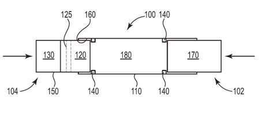
도 1은 연장된 위치에서 예시적인 에어로졸 발생 물품(100)의 개략도이다.
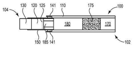
도 2는 인입된 위치에서 도 1의 예시적인 에어로졸 발생 물품(100)의 개략도이다.
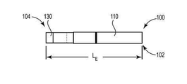
도 3은 연장된 위치에서 다른 예시적인 에어로졸 발생 물품(100)의 개략도이다.
도 4는 인입된 위치에서 도 3의 예시적인 에어로졸 발생 물품(100)의 개략도이다.
도 5는 연장된 위치에서 다른 예시적인 에어로졸 발생 물품(100)의 개략도이다.
도 6은 연장된 위치에서 다른 예시적인 에어로졸 발생 물품(100)의 개략도이다.
도 7은 연장된 위치에서 예시적인 에어로졸 발생 물품(100)의 사시도이다.
도 8은 인입된 위치에서 도 7의 에어로졸 발생 물품(100)의 사시도이다.1 is a schematic view of an exemplary
FIG. 2 is a schematic view of the exemplary
3 is a schematic view of another exemplary
Figure 4 is a schematic view of the exemplary
5 is a schematic diagram of another exemplary
6 is a schematic view of another exemplary
7 is a perspective view of an exemplary
8 is a perspective view of the
개략도는 일정한 비율로 할 필요가 없으며, 제한이 아닌 예시의 목적으로 제공된다. 도면은 본 개시에 설명되는 하나 이상의 양태를 도시한다. 그러나, 도면에 도시되지 않은 다른 측면이 본 발명의 범주 및 사상의 범위 안에 속하는 것임이 이해될 것이다.The schematics are not necessarily to scale and are provided for purposes of illustration and not limitation. The drawings illustrate one or more aspects set forth in this disclosure. However, it is to be understood that other aspects not shown in the drawings fall within the scope and spirit of the present invention.
에어로졸 발생 물품(100)은 근위 단부(102)와 원위 단부(104) 사이로 연장된다. 관형 바디(110)는 에어로졸 발생 물품(100)의 근위 단부(102)에 위치되고, 원위 단부(104) 쪽으로 연장된다. 가연성 열원(130)은 에어로졸 발생 물품(100)의 원위 단부(104)에 위치된다. 에어로졸 발생 기재(120)는 가연성 열원(130)의 하류에 있다. 가연성 열원(130)은 연장된 위치(도 1, 및 도 3 및 도 5 및 도 6 및 도 7)로부터 더 짧은 물품 길이를 갖는 인입된 위치(도 2 및 도 4 및 도 8)로 슬라이딩 가능하다. 화살표는 가연성 열원(130)에 적용된 힘과, 가연성 열원(130)의 결과적인 이동 방향을 나타낸다. 가연성 열원(130)은 인입된 위치에서 관형 바디(110) 내로 적어도 부분적으로 인입한다. 바람직하게, 가연성 열원(130)의 전체 길이는 인입된 위치에서 관형 바디(110) 내로 인입한다.The
관형 바디(110)의 내부 표면(160)은 위에 기재된 바와 같이, 열 반응성 재료를 포함할 수 있다. 바람직하게, 열 반응성 재료는 관형 바디(110)의 원위 단부 부분을 따라 내부 표면(160)의 일부분 상에 배치되거나 이를 형성한다. 열 반응성 재료는 인입된 가연성 열원(130)의 소화를 용이하게 할 수 있다.The
에어로졸 형성 기재(120)는 가연성 열원(130) 및 원위 단부(104)의 하류에 있다. 많은 구현예에서, 내부 관형 요소(150)는 가연성 열원(130)을 유지한다. 가연성 열원(130)은 원통형일 수 있다. 내부 관형 요소(150)는 관형 바디(110)의 원위 단부 내에 적어도 부분적으로 배치되고, 내부 관형 요소(150)는 연장된 위치로부터 인입된 위치로 슬라이딩 가능하다. 예시된 구현예에서, 에어로졸 형성 기재(120)는 내부 관형 요소(150) 내에 적어도 부분적으로 배치되고, 연장된 위치로부터 인입된 위치로 슬라이딩 가능하다. 따라서, 가연성 열원(130)은 내부 관형 요소(150)를 통해 에어로졸 형성 기재(120)에 고정될 수 있다. 내부 관형 요소(150)는 가연성 열원(130)으로부터 에어로졸 형성 기재(120)로의 열 전달을 또한 용이하게 할 수 있다. 천공부 또는 애퍼처(125)는 가열된 에어로졸 형성 기재(120)를 통과하는 흡입 또는 유입구 공기를 제공할 수 있다. 내부 관형 요소(150)는 또한 확산기 또는 전달 요소(185)(도 5 및 도 6에 도시된)를 함유하거나 유지할 수 있다.The
에어로졸 발생 물품(100)은 순차적으로 공극 공간(180) 및 필터 요소(170)를 더 포함할 수 있어, 가연성 열원(130) 및 에어로졸 형성 기재(120)와 동축 정렬에 접한다. 확산기 또는 전달 요소(185)는 공극 공간(180)의 일부분에 배치될 수 있다. 에어로졸 냉각 요소(175)는 공극 공간(180)의 일부분에 배치될 수 있다. 에어로졸 냉각 요소(175)는 마우스피스 필터 요소(170)의 상류에 있을 수 있고, 마우스피스 필터 요소(170)에 접할 수 있다. 필터 요소(170)는 마우스피스 단부(102)의 일부분을 포함할 수 있거나 형성할 수 있다.The
에어로졸 발생 물품(100)은 종래의 궐련과 유사한 길이 및 직경을 가질 수 있다. 에어로졸 발생 물품(100)은 약 60 mm 내지 약 100 mm, 또는 약 70 mm 내지 약 90 mm, 또는 약 70 내지 약 80 mm의 범위에 있는 연장된 길이(LE)(연장된 위치에서)를 가질 수 있다. 에어로졸 발생 물품(100)은 약 40 mm 내지 약 70 mm, 또는 약 40 mm 내지 약 60 mm, 또는 약 50 mm의 범위에 있는 인입 길이(LR)(인입된 위치에서)를 가질 수 있다.The
가연성 열원(130) 및 에어로졸 형성 기재(120)는 약 15 mm 내지 약 20 mm의 범위에 있는 조합된 길이를 가질 수 있다. 필터 요소(170)는 약 10 mm 내지 약 25 mm의 범위에 있는 길이를 가질 수 있다. 공극 공간(180)은 약 20 mm 내지 약 50 mm, 또는 약 25 mm 내지 약 40 mm의 길이를 가질 수 있다.The
선택적인 디텐트 요소(140) 또는 리지 또는 리브 요소는 내부 관형 부재(150)와 맞물리고, 충분한 힘이 디텐트 요소(140)를 극복하고 가연성 열원(130)을 관형 바디(110)로 인입하기 위해 내부 관형 바디(150)에 적용될 때까지 연장된 위치를 유지하도록 구성될 수 있다. 선택적인 접착제(141)는 내부 관형 부재(150)를 관형 부재(110)에 접착하고, 가연성 열원으로부터의 열이 접착제(141)를 용융하고 충분한 힘이 가열된 접착제(141)를 극복하고 가연성 열원(130)을 관형 바디(110)에 완전히 인입시키기 위해 내부 관형 바디(150)에 적용될 때까지 연장된 위치를 유지하도록 구성될 수 있다. 디텐트 요소(140) 및 접착제(141)는 보유 요소로서 위에 지칭된다.The
도 3 및 도 4에 도시된 바와 같이, 필터 요소(170)는 관형 바디(110)의 근위 단부 내에 부분적으로 배치될 수 있고, 노출된 부분은 관형 바디(110)의 근위 단부를 지나 연장된다. 필터 요소(170)는 연장된 필터 위치(도 3)로부터 인입된 필터 요소(도 4)로 슬라이딩 가능하고, 필터 요소(170)는 관형 바디(110)로 인입된 위치에서 적어도 부분적으로 인입한다. 선택적인 디텐트 요소(140) 또는 리지 또는 리브 요소는 필터 요소(170)와 맞물리고, 충분한 힘이 디텐트 요소(140)를 극복하고 필터 요소(170)를 관형 바디(110)로 인입시키기 위해 필터 요소(170)에 적용될 때까지 연장된 위치를 유지하도록 구성될 수 있다. 필터 요소(170)는 셀룰로오스 아세테이트 토우를 포함할 수 있다.3 and 4, the
에어로졸 발생 기재(120)는 가연성 열원(130)에 바로 인접하거나 하류에 위치될 수 있으며, 예를 들어 에어로졸 형성제로서 글리세린을 포함하는 균질화된 담배 재료의 원통형 플러그를 포함하고, 플러그 랩에 의해 둘러싸일 수 있다. 열 전도 요소 또는 내부 관형 부재(150)는 가연성 열원(130)의 후방 부분 및 접하는 에어로졸 형성 기재(120)의 전방 부분을 둘러싸고 그와 접촉할 수 있다.The
도 5는 마우스피스 필터 요소(170)의 상류에 있고 접하는 에어로졸 냉각 요소(175)를 도시한다. 도 5는 에어로졸 형성 기재(120) 하류에 있고 접하는 확산기 또는 전달 요소(185)를 도시한다. 확산기 또는 전달 요소(185)는 가연성 열원(130)과 함께 슬라이딩 가능할 수 있다. 확산기 또는 전달 요소(185)는 내부 관형 부재(150) 내에 함유될 수 있다. 확산기 또는 전달 요소(185)는 내부 관형 부재(150) 내에 함유될 수 있고, 가연성 열원(130) 및 에어로졸 형성 기재(120)와 함께 슬라이딩 가능할 수 있다. 공극 공간(180)은 일단 에어로졸 발생 물품(100)이 인입된 위치에 위치되면 제거될 수 있다. 보유 요소는 관형 바디(110) 및 내부 관형 부재(150)의 접합부에 배치될 수 있다. 이와 같은 유지 부재는 내부 관형 요소(150)와의 관형 바디(110)의 접합부와 오버래핑하는 외부 래퍼 또는, 예시된 바와 같은 접착제(141)일 수 있고, 예를 들어 접착제에 의해 관형 바디(110) 및 내부 관형 요소(150) 둘 모두에 고정된다.FIG. 5 illustrates an
공극 공간(180)은 길이에서 약 15 mm 내지 약 25 mm, 또는 약 20 mm일 수 있고, 공극 공간(180)은 확산기 또는 전달 요소(185)로부터 에어로졸 냉각 요소(175)를 분리한다. 도 5의 에어로졸 발생 물품(100)의 전체 길이는 연장된 위치에서 약 50 mm 내지 약 100 mm, 또는 약 60 mm 내지 약 80 mm, 또는 약 70 mm, 및 인입된 위치에서 약 30 mm 내지 약 70 mm, 또는 약 40 mm 내지 약 60 mm, 또는 약 50 mm일 수 있다. 가연성 열원(130)의 길이는 약 5 mm 내지 약 15 mm, 또는 7 mm 내지 약 11 mm, 또는 약 9 mm 또는 약 10 mm일 수 있다. 에어로졸 형성 기재(120)의 길이는 약 5 mm 내지 약 15 mm, 또는 6 mm 내지 약 10 mm, 또는 약 8 mm 또는 약 9 mm일 수 있다. 확산기 또는 전달 요소(185)의 길이는 약 5 mm 내지 약 15 mm, 또는 7 mm 내지 약 11 mm, 또는 약 9 mm 또는 약 10 mm일 수 있다. 에어로졸 냉각 요소(175)의 길이는 약 7 mm 내지 약 17 mm, 또는 10 mm 내지 약 14 mm, 또는 약 11 mm 또는 약 12 mm일 수 있다. 마우스피스 필터 요소(170)의 길이는 약 7 mm 내지 약 17 mm, 또는 10 mm 내지 약 14 mm, 또는 약 11 mm 또는 약 12 mm일 수 있다.The
도 6은 마우스피스 필터 요소(170) 상류에 있고 이에 접하는 에어로졸 냉각 요소(175)를 도시한다. 도 6은 에어로졸 형성 기재(120) 하류에 있고 이에 접하는 제1 확산기 또는 전달 요소(185), 및 에어로졸 냉각 요소(175) 상류에 있고 이에 접하는 제2 확산기 또는 전달 요소(185)를 도시한다. 확산기 또는 전달 요소(185)는 가연성 열원(130)과 함께 슬라이딩 가능할 수 있다. 내부 관형 부재(150)는 관형 바디(110)의 상당 부분 또는 길이를 따라 그리고 그 내에서 연장될 수 있다. 내부 관형 부재(150)는 관형 바디(110)와 동축에 있을 수 있다.FIG. 6 shows an
내부 관형 부재(150)는 가연성 열원(130)으로부터 에어로졸 냉각 요소(175) 또는 마우스피스 필터 요소(170)로 연장될 수 있다. 확산기 또는 전달 요소(185), 에어로졸 냉각 요소(175), 및 마우스피스 필터 요소(170)는 내부 관형 부재(150)내에 함유되거나 이에 의해 유지될 수 있다. 내부 관형 부재(150)는, 내부 관형 부재(150)가 관형 바디(110) 내에서 붕괴하도록 하고 인입된 위치로 인입하도록 하기 위해(도 8 참조) 취약 영역을 가질 수 있다. 취약 영역은 공극 공간(180)과 동일한 시공간에 위치될 수 있다.The inner
확산기 또는 전달 요소(185) 및 에어로졸 형성 기재(120)는 내부 관형 부재(150) 내에 함유될 수 있고, 가연성 열원(130)과 함께 슬라이딩 가능할 수 있다. 확산기 또는 전달 요소(185)는 인입된 위치에 위치될 때 제2 확산기 또는 전달 요소(185)에 접하거나 접촉할 수 있다. 공극 공간(180)은 일단 에어로졸 발생 물품(100)이 인입된 위치로 붕괴되면 제거될 수 있다. 선택적인 보유 요소는 관형 바디(110) 및 내부 관형 부재(150)의 접합부에 위치될 수 있다. 이와 같은 유지 부재는 관형 바디(110)와 내부 관형 요소(150)의 접합부와 오버래핑하는 접착제 또는 외부 래퍼일 수 있고, 예를 들어 접착제에 의해 관형 바디(110)와 내부 관형 요소(150) 둘 모두에 고정된다.The diffuser or
공극 공간(180)은 약 15 mm 내지 약 25 mm, 또는 약 20 mm의 길이일 수 있고, 공극 공간(180)은 제1 및 제2 확산기 또는 전달 요소(185)를 분리한다. 도 6의 에어로졸 발생 물품(100)의 전체 길이는 연장된 위치에서 약 50 mm 내지 약 100 mm, 또는 약 60 mm 내지 약 80 mm, 또는 약 70 mm일 수 있고, 인입된 위치에서 약 30 mm 내지 약 70 mm, 또는 약 40 mm 내지 약 60 mm, 또는 약 50 mm일 수 있다. 가연성 열원(130)의 길이는 약 5 mm 내지 약 15 mm, 또는 7 mm 내지 약 11 mm, 또는 약 9 mm 또는 약 10 mm일 수 있다. 에어로졸 형성 기재(120)의 길이는 약 5 mm 내지 약 15 mm, 또는 6 mm 내지 약 10 mm, 또는 약 8 mm 또는 약 9 mm일 수 있다. 각각의 제1 및 제2 확산기 또는 전달 요소(185)의 길이 각각은 약 4 mm 내지 약 10 mm, 또는 5 mm 내지 약 9 mm, 또는 약 7 mm 또는 약 8 mm일 수 있다. 에어로졸 냉각 요소(175)의 길이는 약 5 mm 내지 약 15 mm, 또는 8 mm 내지 약 12 mm, 또는 약 10 mm일 수 있다. 마우스피스 필터 요소(170)의 길이는 약 5 mm 내지 약 15 mm, 또는 7 mm 내지 약 11 mm, 또는 약 9 mm 또는 약 10 mm일 수 있다.The
사용 시, 사용자는 에어로졸 형성 기재(120)를 가열하여 에어로졸을 생성하는 가연성 열원(130)을 발화한다. 사용자가 마우스피스(102) 상에서 흡입할 때, 공기는 내부 관형 부재(150) 또는 관형 바디(110)에서 그리고 에어로졸 형성 기재(120)에 인접한 공기 유입구 구멍(125)을 통해 에어로졸 형성 기재(120)를 통해, 팽창 또는 공극(180)을 통해, 필터 요소(170)를 통해 소비자에게 흡인될 수 있다.In use, the user ignites the
일단 에어로졸 발생 기재(120)의 소비가 완료되면, 소비자는 힘을 가연성 열원(130) 및 내부 관형 바디(150)에 적용할 수 있어, 보유 요소 또는 내부 관형 부재 취약 영역을 극복하고 가연성 열원(130)을 관형 바디(110)로 인입시킨다. 일단 가연성 열원(130)이 관형 바디(110) 내로 인입하면, 선택적인 열 반응성 재료(160)는 관형 바디(110) 내에서 가연성 열원(130)을 밀봉하도록 기능할 수 있다. 더욱이, 소비자는 또한, 필터 요소(170)가 관형 바디(110)에 대해 슬라이딩 가능할 수 있을 때 보유 요소(140)(존재 시)를 극복하고 필터 요소(170)를 관형 바디(110)로 인입시키기 위해 힘을 필터 요소(170)에 적용할 수 있다. 관형 바디(110) 내의 가연성 열원(130)의 인입은 가연성 열원(130)을 소화시킨다.Once the consumption of the
Claims (19)
상기 에어로졸 발생 물품의 상기 근위 단부에 위치되고 상기 원위 단부로 연장되는 관형 바디;
상기 에어로졸 발생 물품의 상기 원위 단부에 위치된 가연성 열원; 및
상기 가연성 열원의 하류에 있는 에어로졸 형성 기재;
상기 가연성 열원은 제1 물품 길이를 갖는 연장된 위치로부터 상기 제1 물품 길이보다 작은 제2 물품 길이를 갖는 인입된 위치로 슬라이딩 가능하고, 상기 가연성 열원의 상기 전체 길이는 상기 인입된 위치에서 상기 관형 바디로 인입하는, 에어로졸 발생 물품.An aerosol-generating article having a proximal end and a distal end:
A tubular body located at the proximal end of the aerosol generating article and extending to the distal end;
A combustible heat source located at the distal end of the aerosol generating article; And
An aerosol forming substrate downstream of said combustible heat source;
Wherein the combustible heat source is slidable from an extended position having a first article length to a drawn position having a second article length that is less than the first article length and wherein the total length of the combustible heat source is greater than the total length of the tubular An aerosol-generated article that enters the body.
Applications Claiming Priority (3)
| Application Number | Priority Date | Filing Date | Title |
|---|---|---|---|
| EP15203127.4 | 2015-12-30 | ||
| EP15203127 | 2015-12-30 | ||
| PCT/IB2016/057579 WO2017115196A1 (en) | 2015-12-30 | 2016-12-13 | Retractable heat source for aerosol generating article |
Publications (1)
| Publication Number | Publication Date |
|---|---|
| KR20180098550A true KR20180098550A (en) | 2018-09-04 |
Family
ID=55027588
Family Applications (1)
| Application Number | Title | Priority Date | Filing Date |
|---|---|---|---|
| KR1020187017270A Ceased KR20180098550A (en) | 2015-12-30 | 2016-12-13 | Retractable heat source for aerosol-generating article |
Country Status (18)
| Country | Link |
|---|---|
| US (1) | US11690399B2 (en) |
| EP (1) | EP3397094B1 (en) |
| JP (1) | JP7004657B2 (en) |
| KR (1) | KR20180098550A (en) |
| CN (1) | CN108289514A (en) |
| AR (1) | AR107256A1 (en) |
| AU (1) | AU2016381391A1 (en) |
| BR (1) | BR112018011365B1 (en) |
| CA (1) | CA3008992A1 (en) |
| IL (1) | IL259941A (en) |
| MX (1) | MX2018007735A (en) |
| PH (1) | PH12018501198A1 (en) |
| RU (1) | RU2713242C1 (en) |
| SG (1) | SG11201805507UA (en) |
| TW (1) | TW201729697A (en) |
| UA (1) | UA124421C2 (en) |
| WO (1) | WO2017115196A1 (en) |
| ZA (1) | ZA201803663B (en) |
Cited By (2)
| Publication number | Priority date | Publication date | Assignee | Title |
|---|---|---|---|---|
| KR20210104403A (en) * | 2020-02-17 | 2021-08-25 | 주식회사 케이티앤지 | Aerosol generating article and system comprising adsorbent |
| KR20220051748A (en) | 2020-10-19 | 2022-04-26 | 주식회사 케이티앤지 | Smoking article |
Families Citing this family (59)
| Publication number | Priority date | Publication date | Assignee | Title |
|---|---|---|---|---|
| EP3892125A3 (en) | 2011-09-06 | 2022-01-05 | Nicoventures Trading Limited | Heating smokable material |
| PL2753202T3 (en) | 2011-09-06 | 2016-11-30 | Heating smokeable material | |
| GB201207039D0 (en) | 2012-04-23 | 2012-06-06 | British American Tobacco Co | Heating smokeable material |
| GB201500582D0 (en) * | 2015-01-14 | 2015-02-25 | British American Tobacco Co | Apparatus for heating or cooling a material contained therein |
| WO2016050706A1 (en) * | 2014-09-29 | 2016-04-07 | Philip Morris Products S.A. | Slideable extinguisher |
| GB201511349D0 (en) | 2015-06-29 | 2015-08-12 | Nicoventures Holdings Ltd | Electronic aerosol provision systems |
| GB201511361D0 (en) | 2015-06-29 | 2015-08-12 | Nicoventures Holdings Ltd | Electronic vapour provision system |
| US11924930B2 (en) | 2015-08-31 | 2024-03-05 | Nicoventures Trading Limited | Article for use with apparatus for heating smokable material |
| US20170055584A1 (en) | 2015-08-31 | 2017-03-02 | British American Tobacco (Investments) Limited | Article for use with apparatus for heating smokable material |
| US20170119046A1 (en) | 2015-10-30 | 2017-05-04 | British American Tobacco (Investments) Limited | Apparatus for Heating Smokable Material |
| US11744296B2 (en) | 2015-12-10 | 2023-09-05 | R. J. Reynolds Tobacco Company | Smoking article |
| US10314334B2 (en) | 2015-12-10 | 2019-06-11 | R.J. Reynolds Tobacco Company | Smoking article |
| DK3187057T3 (en) * | 2015-12-31 | 2018-05-28 | Philip Morris Products Sa | AEROSOL GENERATING ITEMS INCLUDING A HEAT CONDUCTIVE ELEMENT AND A SURFACE TREATMENT |
| MX2018007730A (en) * | 2015-12-31 | 2018-08-15 | Philip Morris Products Sa | Breakable aerosol generating article. |
| JP7307678B2 (en) * | 2016-12-21 | 2023-07-12 | フィリップ・モーリス・プロダクツ・ソシエテ・アノニム | Smoking article with extinguishing means |
| CN109996456B (en) | 2016-12-21 | 2021-12-03 | 菲利普莫里斯生产公司 | Smoking article with extinguishing means |
| EP3453268B1 (en) | 2017-09-07 | 2019-12-11 | Philip Morris Products S.a.s. | Aerosol-generating article with improved outermost wrapper |
| CN107647482A (en) * | 2017-10-24 | 2018-02-02 | 谢宏林 | Electronic cigarette |
| EP3720305B1 (en) * | 2017-12-07 | 2022-02-23 | Philip Morris Products S.A. | Aerosol generating article with heat-expandable centering element |
| WO2019141373A1 (en) * | 2018-01-19 | 2019-07-25 | Hauni Maschinenbau Gmbh | Kit system for an hnb smoking article, module carrier for an hnb smoking article, and hnb smoking article |
| EP3513666A1 (en) | 2018-01-23 | 2019-07-24 | Philip Morris Products S.a.s. | Container for aerosol-generating articles with extinguishing means |
| PL3752012T3 (en) | 2018-02-16 | 2022-06-20 | Philip Morris Products S.A. | Wrapping paper pattern for an aerosol-generating article |
| JP7381473B2 (en) * | 2018-02-16 | 2023-11-15 | フィリップ・モーリス・プロダクツ・ソシエテ・アノニム | Aerosol-generating articles with retractable heat sources |
| US10798969B2 (en) | 2018-03-16 | 2020-10-13 | R. J. Reynolds Tobacco Company | Smoking article with heat transfer component |
| BR112020021046A2 (en) * | 2018-05-17 | 2021-01-19 | Philip Morris Products S.A. | MULTISEGMENTED COMPONENT WITH INTUMESCENT COATING |
| US11723399B2 (en) | 2018-07-13 | 2023-08-15 | R.J. Reynolds Tobacco Company | Smoking article with detachable cartridge |
| KR102947055B1 (en) * | 2018-07-26 | 2026-04-03 | 필립모리스 프로덕츠 에스.에이. | Article for forming an aerosol |
| JP7528069B2 (en) * | 2018-10-12 | 2024-08-05 | ジェイティー インターナショナル エスエイ | Aerosol generating device and heating chamber therefor |
| CN109691697B (en) * | 2019-03-01 | 2021-07-30 | 南通醋酸纤维有限公司 | Aerosol generating product, preparation method and application |
| GB201904843D0 (en) | 2019-04-05 | 2019-05-22 | Nicoventures Holdings Ltd | Aerosol provision system |
| US12022859B2 (en) | 2019-07-18 | 2024-07-02 | R.J. Reynolds Tobacco Company | Thermal energy absorbers for tobacco heating products |
| US12075819B2 (en) * | 2019-07-18 | 2024-09-03 | R.J. Reynolds Tobacco Company | Aerosol delivery device with consumable cartridge |
| US12082607B2 (en) | 2019-07-19 | 2024-09-10 | R.J. Reynolds Tobacco Company | Aerosol delivery device with clamshell holder for cartridge |
| US12232542B2 (en) | 2019-07-19 | 2025-02-25 | R.J. Reynolds Tobacco Company | Aerosol delivery device with sliding sleeve |
| US11330838B2 (en) | 2019-07-19 | 2022-05-17 | R. J. Reynolds Tobacco Company | Holder for aerosol delivery device with detachable cartridge |
| US11395510B2 (en) | 2019-07-19 | 2022-07-26 | R.J. Reynolds Tobacco Company | Aerosol delivery device with rotatable enclosure for cartridge |
| US12569004B2 (en) | 2019-07-19 | 2026-03-10 | R.J. Reynolds Tobacco Company | Aerosol delivery device with separable heat source and substrate |
| KR102341841B1 (en) | 2019-08-08 | 2021-12-21 | 주식회사 케이티앤지 | Aerosol generating article comprising thermally conductive wrapper |
| CN115135178A (en) * | 2020-02-20 | 2022-09-30 | 菲利普莫里斯生产公司 | Aerosol-generating article with bridging element with reflection factor |
| US12484610B2 (en) | 2020-04-16 | 2025-12-02 | R.J. Reynolds Tobacco Company | Aerosol delivery device including a segregated substrate |
| US11589616B2 (en) | 2020-04-29 | 2023-02-28 | R.J. Reynolds Tobacco Company | Aerosol delivery device with sliding and axially rotating locking mechanism |
| US11439185B2 (en) | 2020-04-29 | 2022-09-13 | R. J. Reynolds Tobacco Company | Aerosol delivery device with sliding and transversely rotating locking mechanism |
| US12433340B2 (en) | 2021-04-02 | 2025-10-07 | R. J. Reynolds Tobacco Company | Aerosol delivery device consumable unit |
| US12250969B2 (en) | 2021-04-02 | 2025-03-18 | R. J. Reynolds Tobacco Company | Aerosol delivery device with modular lighter |
| US12426634B2 (en) | 2021-04-02 | 2025-09-30 | R. J. Reynolds Tobacco Company | Aerosol delivery device with integrated lighter |
| US12426633B2 (en) | 2021-04-02 | 2025-09-30 | R. J. Reynolds Tobacco Company | Aerosol delivery device with integrated inductive heater |
| US11825872B2 (en) | 2021-04-02 | 2023-11-28 | R.J. Reynolds Tobacco Company | Aerosol delivery device with protective sleeve |
| EP4082364A1 (en) * | 2021-04-26 | 2022-11-02 | BIC Violex Single Member S.A. | A heat transfer assembly |
| AT524684B1 (en) * | 2021-05-12 | 2022-08-15 | Tannpapier Gmbh | tipping paper |
| WO2023012921A1 (en) * | 2021-08-04 | 2023-02-09 | 日本たばこ産業株式会社 | Flavor generating article and smoking system |
| US12426637B2 (en) | 2021-08-17 | 2025-09-30 | Rai Strategic Holdings, Inc. | Inductively heated aerosol delivery device consumable |
| JP2025506897A (en) * | 2022-03-01 | 2025-03-13 | フィリップ・モーリス・プロダクツ・ソシエテ・アノニム | Aerosol-generating article having a heat-shrinkable wrapper |
| EP4309526A1 (en) * | 2022-07-22 | 2024-01-24 | JT International SA | Heating unit with intumescent material insulation for an aerosol-generating device |
| US12357024B2 (en) | 2022-08-30 | 2025-07-15 | R. J. Reynolds Tobacco Company | Aerosol delivery device with static ignitor contacts |
| US12329199B2 (en) | 2022-08-30 | 2025-06-17 | R.J. Reynolds Tobaco Company | Aerosol delivery device with improved mouthpieces |
| US12564221B2 (en) | 2022-12-14 | 2026-03-03 | R.J. Reynolds Tobacco Company | Aerosol delivery device with deflectable or collapsible housing |
| US12564220B2 (en) | 2022-12-14 | 2026-03-03 | R.J. Reynolds Tobacco Company | Aerosol delivery device with automatic consumable loading and ejecting |
| US12471639B2 (en) | 2022-12-14 | 2025-11-18 | R.J. Reynolds Tobacco Company | Aerosol delivery device with improved cartridge loading |
| CN116035280B (en) * | 2023-01-05 | 2026-04-17 | 深圳市赛尔美电子科技有限公司 | Apparatus for manufacturing heating structure, method for manufacturing heating structure and heating structure |
Family Cites Families (21)
| Publication number | Priority date | Publication date | Assignee | Title |
|---|---|---|---|---|
| US2779340A (en) * | 1954-08-16 | 1957-01-29 | Mansfield Lee | Cigarette holder |
| JPS52143167A (en) * | 1976-05-21 | 1977-11-29 | Kanichi Itakura | Selffextinguishing smoking pipe |
| JPS5419997Y2 (en) * | 1976-06-22 | 1979-07-20 | ||
| US4116204A (en) | 1976-11-15 | 1978-09-26 | Kline James E | Collapsible telescopic water pipe |
| US5033483A (en) * | 1985-10-28 | 1991-07-23 | R. J. Reynolds Tobacco Company | Smoking article with tobacco jacket |
| JPS6363395U (en) * | 1986-10-16 | 1988-04-26 | ||
| US5040552A (en) | 1988-12-08 | 1991-08-20 | Philip Morris Incorporated | Metal carbide heat source |
| US5285798A (en) | 1991-06-28 | 1994-02-15 | R. J. Reynolds Tobacco Company | Tobacco smoking article with electrochemical heat source |
| US5468266A (en) | 1993-06-02 | 1995-11-21 | Philip Morris Incorporated | Method for making a carbonaceous heat source containing metal oxide |
| JP2000004865A (en) * | 1998-06-25 | 2000-01-11 | Yasuyuki Moriyama | Fire extinguishing apparatus attached to cigarette |
| CN2478371Y (en) * | 2001-03-05 | 2002-02-27 | 胡湘克 | Cigarette with self-extinguishing cigarette end |
| CN1382402A (en) * | 2001-04-25 | 2002-12-04 | 于万盛 | Cigarette sleeve for extinguishing fire |
| MX2010001649A (en) | 2007-08-10 | 2010-03-11 | Philip Morris Prod | Distillation-based smoking article. |
| CN201467987U (en) * | 2009-08-27 | 2010-05-19 | 李智钊 | Portable put out device for cigarettes |
| ES2681834T5 (en) * | 2010-03-26 | 2022-10-04 | Japan Tobacco Inc | smoking article |
| EP2625974A1 (en) * | 2012-02-13 | 2013-08-14 | Philip Morris Products S.A. | Aerosol-generating article having a flavour-generating component |
| EP2954792B2 (en) * | 2013-03-08 | 2022-06-29 | Japan Tobacco, Inc. | Package |
| CN103720037A (en) * | 2013-12-30 | 2014-04-16 | 广东中烟工业有限责任公司 | Method for independently regulating smoke concentration of cigarette and telescopic cigarette |
| CN103932390A (en) * | 2014-05-04 | 2014-07-23 | 徐亦隽 | Self-quenching cigarette and application method thereof |
| CN106455684B (en) * | 2014-05-30 | 2019-12-10 | 菲利普莫里斯生产公司 | Cover for extinguishing smoking articles |
| CN204393346U (en) * | 2014-12-12 | 2015-06-17 | 方雨辰 | Cigarette extinguisher |
-
2016
- 2016-12-13 RU RU2018123700A patent/RU2713242C1/en active
- 2016-12-13 JP JP2018534701A patent/JP7004657B2/en active Active
- 2016-12-13 BR BR112018011365-4A patent/BR112018011365B1/en not_active IP Right Cessation
- 2016-12-13 CA CA3008992A patent/CA3008992A1/en active Pending
- 2016-12-13 US US16/066,914 patent/US11690399B2/en active Active
- 2016-12-13 WO PCT/IB2016/057579 patent/WO2017115196A1/en not_active Ceased
- 2016-12-13 AU AU2016381391A patent/AU2016381391A1/en not_active Abandoned
- 2016-12-13 UA UAA201805887A patent/UA124421C2/en unknown
- 2016-12-13 MX MX2018007735A patent/MX2018007735A/en unknown
- 2016-12-13 EP EP16819373.8A patent/EP3397094B1/en active Active
- 2016-12-13 CN CN201680070487.8A patent/CN108289514A/en active Pending
- 2016-12-13 KR KR1020187017270A patent/KR20180098550A/en not_active Ceased
- 2016-12-13 SG SG11201805507UA patent/SG11201805507UA/en unknown
- 2016-12-27 TW TW105143353A patent/TW201729697A/en unknown
- 2016-12-29 AR ARP160104069A patent/AR107256A1/en active IP Right Grant
-
2018
- 2018-06-01 ZA ZA2018/03663A patent/ZA201803663B/en unknown
- 2018-06-06 PH PH12018501198A patent/PH12018501198A1/en unknown
- 2018-06-11 IL IL259941A patent/IL259941A/en unknown
Cited By (2)
| Publication number | Priority date | Publication date | Assignee | Title |
|---|---|---|---|---|
| KR20210104403A (en) * | 2020-02-17 | 2021-08-25 | 주식회사 케이티앤지 | Aerosol generating article and system comprising adsorbent |
| KR20220051748A (en) | 2020-10-19 | 2022-04-26 | 주식회사 케이티앤지 | Smoking article |
Also Published As
| Publication number | Publication date |
|---|---|
| UA124421C2 (en) | 2021-09-15 |
| ZA201803663B (en) | 2019-07-31 |
| AU2016381391A1 (en) | 2018-06-28 |
| EP3397094A1 (en) | 2018-11-07 |
| CN108289514A (en) | 2018-07-17 |
| CA3008992A1 (en) | 2017-07-06 |
| BR112018011365B1 (en) | 2021-11-16 |
| IL259941A (en) | 2018-07-31 |
| US11690399B2 (en) | 2023-07-04 |
| MX2018007735A (en) | 2018-11-09 |
| WO2017115196A1 (en) | 2017-07-06 |
| JP7004657B2 (en) | 2022-01-21 |
| AR107256A1 (en) | 2018-04-11 |
| TW201729697A (en) | 2017-09-01 |
| RU2713242C1 (en) | 2020-02-04 |
| SG11201805507UA (en) | 2018-07-30 |
| EP3397094B1 (en) | 2020-02-05 |
| JP2019506852A (en) | 2019-03-14 |
| PH12018501198A1 (en) | 2019-01-28 |
| US20190000142A1 (en) | 2019-01-03 |
| BR112018011365A2 (en) | 2018-12-04 |
Similar Documents
| Publication | Publication Date | Title |
|---|---|---|
| KR20180098550A (en) | Retractable heat source for aerosol-generating article | |
| EP3397084B1 (en) | Breakable aerosol generating article | |
| JP6961597B2 (en) | Holder for aerosol-generating goods | |
| US10595558B2 (en) | Smoking article comprising a wrapper with a plurality of projections provided on an inner surface thereof | |
| KR102506834B1 (en) | Smoking article comprising a friction ignitable combustible carbonaceous heat source | |
| KR102384544B1 (en) | Smoking article with non-overlapping, radially separated, dual heat-conducting elements | |
| WO2017115188A1 (en) | Extinguisher for aerosol generating article | |
| KR102305797B1 (en) | Aerosol-generating article with improved outermost wrapper | |
| KR20170066335A (en) | Slideable extinguisher | |
| KR20180099656A (en) | Holder for aerosol-generating article | |
| WO2017115183A1 (en) | Apparatus for aerosol generating article | |
| KR20210009314A (en) | Multi-segment component with intumescent coating | |
| HK1262070A1 (en) | Retractable heat source for aerosol generating article | |
| HK1262070B (en) | Retractable heat source for aerosol generating article |
Legal Events
| Date | Code | Title | Description |
|---|---|---|---|
| PA0105 | International application |
Patent event date: 20180618 Patent event code: PA01051R01D Comment text: International Patent Application |
|
| PG1501 | Laying open of application | ||
| A201 | Request for examination | ||
| PA0201 | Request for examination |
Patent event code: PA02012R01D Patent event date: 20211117 Comment text: Request for Examination of Application |
|
| E902 | Notification of reason for refusal | ||
| PE0902 | Notice of grounds for rejection |
Comment text: Notification of reason for refusal Patent event date: 20240201 Patent event code: PE09021S01D |
|
| E601 | Decision to refuse application | ||
| PE0601 | Decision on rejection of patent |
Patent event date: 20240408 Comment text: Decision to Refuse Application Patent event code: PE06012S01D Patent event date: 20240201 Comment text: Notification of reason for refusal Patent event code: PE06011S01I |