KR20180098467A - Horizontal millstone engine - Google Patents
Horizontal millstone engine Download PDFInfo
- Publication number
- KR20180098467A KR20180098467A KR1020170025147A KR20170025147A KR20180098467A KR 20180098467 A KR20180098467 A KR 20180098467A KR 1020170025147 A KR1020170025147 A KR 1020170025147A KR 20170025147 A KR20170025147 A KR 20170025147A KR 20180098467 A KR20180098467 A KR 20180098467A
- Authority
- KR
- South Korea
- Prior art keywords
- engine
- horizontal
- crankshaft
- combustion chamber
- horizontal bar
- Prior art date
- Legal status (The legal status is an assumption and is not a legal conclusion. Google has not performed a legal analysis and makes no representation as to the accuracy of the status listed.)
- Granted
Links
Images




Classifications
-
- F—MECHANICAL ENGINEERING; LIGHTING; HEATING; WEAPONS; BLASTING
- F02—COMBUSTION ENGINES; HOT-GAS OR COMBUSTION-PRODUCT ENGINE PLANTS
- F02B—INTERNAL-COMBUSTION PISTON ENGINES; COMBUSTION ENGINES IN GENERAL
- F02B75/00—Other engines
- F02B75/16—Engines characterised by number of cylinders, e.g. single-cylinder engines
- F02B75/18—Multi-cylinder engines
- F02B75/24—Multi-cylinder engines with cylinders arranged oppositely relative to main shaft and of "flat" type
-
- F—MECHANICAL ENGINEERING; LIGHTING; HEATING; WEAPONS; BLASTING
- F02—COMBUSTION ENGINES; HOT-GAS OR COMBUSTION-PRODUCT ENGINE PLANTS
- F02B—INTERNAL-COMBUSTION PISTON ENGINES; COMBUSTION ENGINES IN GENERAL
- F02B75/00—Other engines
- F02B75/02—Engines characterised by their cycles, e.g. six-stroke
-
- F—MECHANICAL ENGINEERING; LIGHTING; HEATING; WEAPONS; BLASTING
- F02—COMBUSTION ENGINES; HOT-GAS OR COMBUSTION-PRODUCT ENGINE PLANTS
- F02B—INTERNAL-COMBUSTION PISTON ENGINES; COMBUSTION ENGINES IN GENERAL
- F02B75/00—Other engines
- F02B75/02—Engines characterised by their cycles, e.g. six-stroke
- F02B2075/022—Engines characterised by their cycles, e.g. six-stroke having less than six strokes per cycle
- F02B2075/027—Engines characterised by their cycles, e.g. six-stroke having less than six strokes per cycle four
Landscapes
- Engineering & Computer Science (AREA)
- Chemical & Material Sciences (AREA)
- Combustion & Propulsion (AREA)
- Mechanical Engineering (AREA)
- General Engineering & Computer Science (AREA)
- Cylinder Crankcases Of Internal Combustion Engines (AREA)
Abstract
Description
본 발명은 내연기관에 있어서 차체 무게중심을 낮추어 코너링 시 안정성 확보 및 엔진진동에 의한 차량진동을 저감하기 위하여 무게중심을 낮게 함으로 증폭을 작게 할 수 있는 기존의 수직형엔진 배치에서 수평형 배치를 기본으로 하고, 크랭크축 대신 수평바를 설치하여 효율을 높일 수 있는 것이다.The present invention relates to a conventional vertical engine arrangement capable of reducing the amplification by lowering the center of gravity of the internal combustion engine in order to lower the center of gravity of the vehicle body and to secure stability in cornering and to reduce vehicle vibration caused by engine vibration. And a horizontal bar is provided in place of the crankshaft to increase the efficiency.
본 발명은 수평형 엔진에 관한 것으로서, 보다 상세하게는 하나의 실린더가 양단에 두 개의 연소실로 구분되어 실린더 블록에 형성되는 실린더 보어의 수를 감소하고 기존의 크랭크축 대신 수평바를 설치한 수평형 엔진에 관한 것이다.The present invention relates to a horizontal type engine, and more particularly, to a horizontal type engine in which one cylinder is divided into two combustion chambers at both ends to reduce the number of cylinder bores formed in the cylinder block and a horizontal bar instead of a conventional crankshaft. .
일반적으로, 엔진은 흡/배기장치가 결합되는 실린더헤드, 상기 실린더헤드가 결합되는 실린더 블록, 실린더 블록에 형성된 실린더 보어에 슬라이딩 결합하는 피스톤, 상기 피스톤과 크랭크 축의 사이에 개재되어 피스톤의 직선 운동을 크랭크 축의 회전운동으로 변환하는 커넥팅 로드를 포함한다.In general, the engine is provided with a cylinder head to which an intake / exhaust device is coupled, a cylinder block to which the cylinder head is coupled, a piston to be slidably engaged with a cylinder bore formed in the cylinder block, and a linear motion of the piston interposed between the piston and the crankshaft And a connecting rod for converting into a rotational motion of the crankshaft.
상기 엔진은 실린더 보어의 배열 형태에 따라 구분될 수 있으며, 그 중 수평대향형 엔진이 도 1에 도시되어 있다.The engine can be classified according to the arrangement of the cylinder bores, of which a horizontally opposed engine is shown in Fig.
도 1에 도시된 바와 같이 종래 기술에 따른 수평 대향형 엔진은 하나 이상의 실린더 보어(3)가 형성된 실린더 블록(5,7)이 수평상에서 마주하도록 배치되어 있으며, 상기 각각의 실린더 블록에 형성된 실린더 보어(3)에 각각의 피스톤(9,11)이 미끄러져 운동할 수 있도록 결합 된다.As shown in FIG. 1, the conventional horizontal opposed engine has cylinder blocks 5, 7 formed with one or more cylinder bores 3 so as to face each other in a horizontal direction, and the cylinder bores (9, 11) are slidably engaged with the piston (3).
상기 피스톤(9,11)은 각각의 커넥팅 로드(13,15)에 의해 크랭크 축(17)과 연결된다. 즉, 상기 커넥팅 로드(13,15)의 스 몰 엔드(small end)는 피스톤(9,11)과 핀으로 연결되며, 상기 커넥팅 로드(13,15)의 빅 엔드(big end)는 크랭크 축(17) 의 크랭크핀으로 연결된다.The pistons (9, 11) are connected to the crankshaft (17) by respective connecting rods (13, 15). That is, the small ends of the connecting
상기의 구성에 따라 연소실로 흡입된 혼합기를 연소/폭발시키고, 상기 혼합기의 폭발력에 의해 운동하는 상기 피스톤(9,11)의 직선 운동이 커넥팅 로드(13,15)에 의해 크랭크 샤프트(17)의 회전운동으로 변환된다.The linear motions of the pistons 9 and 11 which are moved by the explosive force of the mixer are transmitted to the crankshaft 17 by the connecting
이때, 상기의 구성에 의한 종래의 수평대향형 엔진은 흡입, 압축, 폭발, 배기의 4행정을 1싸이클로 하여 구동되며, 설정된 점화순서에 따라 각 실린더 보어에 형성된 연소실의 연료를 점화시킨다.At this time, the conventional horizontal opposed engine according to the above construction is driven by one cycle of four strokes of suction, compression, explosion and exhaust, and ignites the fuel in the combustion chamber formed in each cylinder bore according to the set ignition sequence.
그러나, 상기의 구성에 의한 종래의 수평 대향형 엔진은 실린더 블록에 형성되는 실린더 보어의 수가 증가함에 따라 크랭크축의 길이가 길어지게 되며, 크랭크축의 길이가 길어질수록 진동/소음 성능(NVH) 및 내구성이 악화되는 문제점이 있었다.However, in the conventional horizontally opposed type engine having the above-described configuration, the length of the crankshaft becomes longer as the number of the cylinder bores formed in the cylinder block increases. As the length of the crankshaft becomes longer, the vibration / noise performance (NVH) and durability There was a problem that it deteriorated.
본 발명은 기존의 수평대향형 엔진에서 엔진의 크기를 줄이기 위한 것으로서, 하나의 실린더 보어 양단에 피스톤과 연소실을 배치하고 피스톤은 커넥팅 로드로 연결되며, 동일한 평면에서 상기 실린더 보어 측면에 또 다른 실린더 보어를 배치하고 상기와 동일한 방법으로 피스톤과 연소실 및 커넥팅 로드를 설치한다. 커넥팅 로드 사이에 수평바를 연결하고 수평바 중간에 일자형 홈을 구비하여 크랭크 축을 회전운동 시킬 수 있도록 한다.In order to reduce the size of an engine in a conventional horizontally opposed engine, a piston and a combustion chamber are disposed at both ends of one cylinder bore, the piston is connected to a connecting rod, and another cylinder bore And the piston, the combustion chamber, and the connecting rod are installed in the same manner as described above. A horizontal bar is connected between the connecting rods and a straight groove is provided in the middle of the horizontal bar so that the crankshaft can be rotated.
발명의 구성 및 작용Structure and function of the invention
본 발명에 따른 수평 맷돌 형 엔진은 실린더 보어 2개가 동일 평면상에서 간격을 가지고 수평으로 평행으로 배치되며 각각의 실린더 보어는 양단에 연소실을 갖는 피스톤이 2개 대칭으로 설치되며 연소실 외곽에는 흡배기 밸브가 설치된다. 피스톤은 커넥팅 로드로 연결되며, 평행하게 설치된 다른 실린더 보어의 커넥팅 로드와 중앙부에 일자형 홈이 구비된 수평바로 연결된다. 실린더 보어가 2개 수평으로 배치된 형태는 4행정 엔진을 구성하며, 다른 실시 예로 4행정 엔진을 직각방향으로 배치하여 상하로 연결하면 8행정 엔진을 구성할 수 있게 된다. 크랭크축을 회전시키는 방법은 수평바 중앙부에 형성된 일자형 홈에 크랭크축을 끼우고 엔진의 작동에 의하여 수평바가 직선왕복 운동하면 크랭크축은 회전운동으로 변환된다.In the horizontal mill type engine according to the present invention, two cylinder bores are disposed on the same plane and horizontally and parallel to each other. Each of the cylinder bores is provided with two pistons having combustion chambers at both ends symmetrically and an intake and exhaust valve is installed outside the combustion chamber do. The piston is connected to the connecting rod, and is connected to a connecting rod of another cylinder bore provided in parallel and a horizontal bar having a straight groove at the center. In the case where two cylinder bores are horizontally arranged, a four-stroke engine is constituted. In another embodiment, when the four-stroke engine is arranged in a perpendicular direction and connected vertically, an eight-stroke engine can be constructed. In a method of rotating the crankshaft, a crankshaft is inserted into a straight groove formed at the center of the horizontal bar, and when the horizontal bar is linearly reciprocated by the operation of the engine, the crankshaft is converted into rotational motion.
본 발명에 따른 수평 맷돌형 엔진에 의하면, 하나의 실린더 보어를 이용하여 양단에 두 개의 연소실을 형성할 수 있어 엔진의 부피를 획기적으로 감소시킬 수 있다.According to the horizontal mill-type engine of the present invention, two combustion chambers can be formed at both ends by using one cylinder bore, so that the volume of the engine can be drastically reduced.
또한, 본 발명에 따른 수평 맷돌형 엔진은 분리된 실린더 보어의 사이에 수평바를 설치하고 수평바 중간 일자형 홈을 이용하여 왕복운동을 회전운동으로 변환하여 기존의 크랭크축을 생략함으로 종래의 수평 대향형 엔진과 비교하여 크기가 감소하므로 엔진의 구조를 단순화 할 수 있다.Further, in the horizontal mill type engine according to the present invention, a horizontal bar is provided between the separated cylinder bores and the reciprocating motion is converted into rotational motion by using the horizontal bar middle straight groove, and the conventional crankshaft is omitted, It is possible to simplify the structure of the engine.
제1도는 기존의 수평대향형 엔진
제2도는 4행정 수평맷돌형 엔진 평면도
제3도는 4행정 수평맷돌형 엔진 단면도(중심점)
제4도는 4행정 수평맷돌형 엔진 단면도(단부점)
제5도는 상부 좌에서 우 방향으로 회전하는 도면
제6도는 하부 우에서 좌 방향으로 회전하는 도면
제7도는 수평바의 일자형 홈이 직선인 형태
제8도는 수형바의 일자형 홈이 직선인 8행정 형태
제9도는 수형바의 일자형 홈이 직선인 8행정의 다른 실시예1 shows a conventional horizontal opposed engine
The second figure shows the four-stroke horizontal mill type engine plan
Figure 3 shows the four-stroke horizontal mill type engine cross section (center point)
4 shows a four-stroke horizontal mill type engine section (end point)
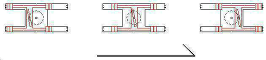
FIG. 5 is a view showing the rotation from the upper left to the right direction
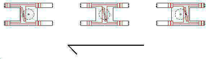
6 is a view showing a rotation in a leftward direction from a lower right;
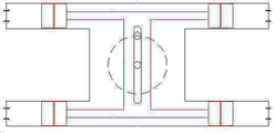
7 is a cross-sectional view in which the straight grooves of the horizontal bar are straight
Fig. 8 shows an eight-stroke configuration in which the straight groove of the male bar is straight
Fig. 9 is a view showing another embodiment of eight-stroke in which the straight groove of the male bar is straight
본 발명에 따른 수평 맷돌 형 엔진은 실린더 보어 2개가 동일 평면상에서 간격을 가지고 수평으로 평행으로 배치되며 각각의 실린더 보어는 양단에 연소실을 갖는 피스톤이 2개 대칭으로 설치되며 연소실 외곽에는 흡배기 밸브가 설치된다. 피스톤은 커넥팅 로드로 연결되며, 평행하게 설치된 다른 실린더 보어의 커넥팅 로드와 중앙부에 일자형 홈이 구비된 수평바로 연결된다. 실린더 보어가 2개 수평으로 배치된 형태는 4행정 엔진을 구성한다.In the horizontal mill type engine according to the present invention, two cylinder bores are disposed on the same plane and horizontally and parallel to each other. Each of the cylinder bores is provided with two pistons having combustion chambers at both ends symmetrically and an intake and exhaust valve is installed outside the combustion chamber do. The piston is connected to the connecting rod, and is connected to a connecting rod of another cylinder bore provided in parallel and a horizontal bar having a straight groove at the center. A configuration in which two cylinder bores are horizontally arranged forms a four-stroke engine.
크랭크축을 회전시키는 방법은 수평바 중앙부에 형성된 일자형 홈에 크랭크축을 끼우고 엔진의 작동에 의하여 수평바가 직선왕복 운동하면 크랭크축은 회전운동으로 변환된다.In a method of rotating the crankshaft, a crankshaft is inserted into a straight groove formed at the center of the horizontal bar, and when the horizontal bar is linearly reciprocated by the operation of the engine, the crankshaft is converted into rotational motion.
이하, 첨부된 도면을 참조하여 본 발명에 따른 수평 맷돌형 4행정 엔진의 일 실시 예에 대해서 상세히 설명한다.Hereinafter, an embodiment of a horizontal mill-type four-stroke engine according to the present invention will be described in detail with reference to the accompanying drawings.
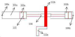
도 2에는 본 발명의 일 실시 예에 따른 수평 맷돌형 4행정 엔진의 구성이 평면 단면도 형태로 도시되어 있다. 제1 실린더 보어(100)에는 실린더 보어 양단에 제1연소실(101a) 및 제2연소실(101b)이 설치되며 연소실에는 흡배기밸브(106a,106b)가 설치된다. 실린더 보어 내부에는 직선운동을 하는 피스톤(102a, 102b)가 설치되며, 피스톤을 연결하는 커넥팅 로드(103a)가 설치된다.FIG. 2 is a plan sectional view showing the construction of a horizontal mill-type four-stroke engine according to an embodiment of the present invention. The
제1 실린더 보어와 일정한 거리를 두고 수평바(104)로 연결된 제2 실린더 보어(200)가 평행하게 배치된다. 제2 실린더 보어도 상기의 제1 실린더 보어와 동일하게 제3연소실(107a)및 제4연소실(107b)과 피스톤(108a, 108b)이 설치되며, 피스톤은 커넥팅 로드(103b)에 의하여 강접된다.A second cylinder bore (200) connected by a horizontal bar (104) is disposed parallel to the first cylinder bore at a certain distance. Similarly to the first cylinder bore, the second cylinder bore is provided with a
제1 실린더 보어와 제2 실린더 보어는 제1 실린더 보어(100)의 커넥팅 로드(103a)와 제2 실린더 보어(200)의 커넥팅 로드(103b)를 수평바(104)에 의하여 강접한다. 이상에서 피스톤과 커넥팅 로드 및 커넥팅 로드 간의 연결은 핀에 의하여 연결하는 대신 핀이 없이 강접방식으로 연결하는 것이 바람직하다.The connecting
도 2에서 엔진의 작동방식은 표1의 각 연소실의 행정에 따라 좌우 방향으로 직선 왕복운동을 한다. 엔진작동 시 상기의 흡배기밸브(106a, 106b, 111a, 111b)의 작동은 당업자에게 자명한 사항으로 상세한 설명은 생략한다. 또한, 도면에 도시되지 않는 흡배기 밸브를 구동시키기 위한 캠기구의 작동도 당업자에게 자명한 사항으로 상세한 설명은 생략한다.In Fig. 2, the manner of operation of the engine is linearly reciprocating in the lateral direction according to the strokes of the respective combustion chambers shown in Table 1. Operation of the intake and
도 3 및 도 4는 본 발명의 일 실시 예에 따른 수평 맷돌형 4행정 엔진의 구성이 수직 단면도 형태로 도시되어 있다.FIG. 3 and FIG. 4 show a vertical cross-sectional view of the construction of a horizontal mill-type four-stroke engine according to an embodiment of the present invention.
도 3에서 도시되지 않은 바퀴를 구동시키는 크랭크축(112a, 112b)은 기존 엔진의 크랭크축과 달리 수직으로 배치되며, 2가지 부분으로 구성된다. 하부크랭크축(112a)는 회전축이 고정된 축이며, 상부크랭크축(112b)은 회전축이 고정되지 않고 수평바(104)의 중간부에 설치된 일자형 홈(105)에 끼워지는 형태로 수평바의 직선운동에 따라 원 운동하여 하부 크랭크축(112a)을 회전운동으로 변환시키는 역할을 한다.The
도 3은 수평바(104)가 실린더 보어의 중간점에 있는 상태이고3 shows a state in which the
도 4는 수평바(104)가 실린더 보어의 우측면에 있는 상태이다.4 shows a state in which the
도 5는 크랭크축이 우회전 시 좌에서 우로 진행하는 상태이다.Fig. 5 shows a state in which the crankshaft is moved from left to right when turning right.
도 6은 크랭크축이 우회전 시 우에서 좌로 진행하는 상태이다.Fig. 6 shows a state in which the crankshaft moves from right to left in a right turn.
수평바(104)의 중간부에 구비된 일자형 홈(105)은 크랭크축의 원활한 회전을 위하여 사선으로 가공되는 것이 바람직하며 사선의 방향은 상부가 좌측 하부가 우측인 형태가 바람직하다. 이와 같이 일자형 홈(105)을 사선방향으로 가공하는 목적은 수평바(104)가 일자형 홈(105)을 이용하여 상부 크랭크축(112b)을 수평방향으로 밀 때 좌우의 방향이 바뀌는 시점에서 역 방향으로 회전되지 않게 하려는 목적에서 이다.It is preferable that the
역방향으로 회전하지 않고 항상 시계방향으로 회전할 수 있는 원리는 빗면을 구성하므로 일자형 홈(105)내에서 상부 크랭크축 상부(112b)이 직선 운동 시 일자형 홈을 따라 쉽게 진행하는 방향으로 움직이면 계속 같은 방향으로 회전할 수 있기 때문이다.Since the
4행정 구조에서 또 다른 실시예로서 수평바의 일자형 홈이 빗면을 형성하지 않고 일직선으로 가공될 수 있다. 제 7도에서 제 9도는 이에 따른 도면이다.As another embodiment in the four-stroke structure, the straight groove of the horizontal bar can be straightened without forming the oblique surface. Figures 7 to 9 are views thereof.
제7도는 수평바의 일자형 홈이 직선인 형태7 is a cross-sectional view in which the straight grooves of the horizontal bar are straight
제8도는 수형바의 일자형 홈이 직선인 8행정 형태이며, 같은 평면에 배치되며 90도 틀어서 배치된다.FIG. 8 shows an eight-stroke shape in which the straight grooves of the male bars are straight, arranged in the same plane, and arranged at an angle of 90 degrees.
제9도는 수형바의 일자형 홈이 직선인 8행정의 다른 실시예Fig. 9 shows another embodiment of eight-stroke in which the straight groove of the male bar is straight
제9도는 8행정의 다른 실시예이며, 제8도와 다른점은 8행정 기관 배치시 4행정기관이 상하로 겹치는 방법이며, 90도 만큼 틀어서 배치한다. 이는 엔진 배치상 평면의 넓이를 줄일 수 있는 이점이 있다.Fig. 9 is another embodiment of eight strokes, and the eighth embodiment differs from the eighth embodiment in that four-stroke organs are arranged vertically in an eight-stroke engine arrangement, and are disposed with a difference of 90 degrees. This has the advantage that the width of the plane on the engine layout can be reduced.
3 : 실린더 보어
5 : 실린더 블록
7 : 실린더 블록
9 : 피스톤
11 : 피스톤
13 : 커넥팅 로드
15 : 커넥팅 로드
17 : 크랭크축
100 : 제1 실린더 보어
200 : 제2 실린더 보어
101a : 제1연소실
101b : 제2연소실
102a : 피스톤
102b : 피스톤
103a : 커넥팅 로드
103b : 커넥팅 로드
104 : 수평바
105 : 일자형 홈
106a : 흡배기밸브
106b : 흡배기밸브
107a : 제3연소실
107b : 제4연소실
108a : 피스톤
108b : 피스톤
109 : 상부 크랭크축의 궤적
110 : 피스톤 링
111a : 흡배기밸브
111b : 흡배기밸브
112a : 하부 크랭크축
112b : 상부 크랭크축(붉은색 표현)
113 : 엔진룸 내부3: Cylinder bore
5: Cylinder block
7: Cylinder block
9: Piston
11: Piston
13: Connecting rod
15: Connecting rod
17: Crankshaft
100: first cylinder bore
200: second cylinder bore
101a: first combustion chamber
101b: a second combustion chamber
102a: Piston
102b: piston
103a: connecting rod
103b: connecting rod
104: Horizontal bar
105: Straight groove
106a: intake and exhaust valve
106b: intake and exhaust valve
107a: Third combustion chamber
107b: fourth combustion chamber
108a: piston
108b: piston
109: locus of the upper crankshaft
110: Piston ring
111a: intake and exhaust valve
111b: intake and exhaust valve
112a: Lower crankshaft
112b: upper crankshaft (in red)
113: Engine room interior
Claims (3)
실린더 보어 2개가 동일 평면상에 평행으로 배치되며 각각의 실린더 보어는 양단에 연소실을 갖는 피스톤이 2개 대칭으로 설치되며 각 피스톤은 커넥팅 로드로 연결되며, 2개의 커넥팅 로드는 중앙부에 일자형 홈이 구비된 수평바로 연결되는 4행정 엔진을 구성하는 수평 맷돌 형 엔진In a horizontal engine, which is a kind of internal combustion engine,
Two cylinder bores are arranged in parallel on the same plane, two pistons each having a combustion chamber at both ends thereof are symmetrically installed, each piston is connected by a connecting rod, and the two connecting rods have a straight groove at the center thereof Horizontal mill type engine constituting a four-stroke engine
실린더 보어 2개가 동일 평면상에 평행으로 배치되며 각각의 실린더 보어는 양단에 연소실을 갖는 피스톤이 2개 대칭으로 설치되며 각 피스톤은 커넥팅 로드로 연결되며, 2개의 커넥팅 로드는 중앙부에 일자형 홈이 구비된 수평바로 연결되는 4행정기관과 동일한 구조로 상하로 겹치되 90도 틀어서 배치되어 8행정기관을 구성하는 수평 맷돌 형 엔진
In a horizontal engine, which is a kind of internal combustion engine,
Two cylinder bores are arranged in parallel on the same plane, two pistons each having a combustion chamber at both ends thereof are symmetrically installed, each piston is connected by a connecting rod, and the two connecting rods have a straight groove at the center thereof A horizontal mill-type engine constituting an eight-stroke engine, which is arranged in a state of being flipped vertically with the same structure as that of the four-stroke engine connected to the horizontal,
Priority Applications (1)
| Application Number | Priority Date | Filing Date | Title |
|---|---|---|---|
| KR1020170025147A KR101963950B1 (en) | 2017-02-25 | 2017-02-25 | Horizontal millstone engine |
Applications Claiming Priority (1)
| Application Number | Priority Date | Filing Date | Title |
|---|---|---|---|
| KR1020170025147A KR101963950B1 (en) | 2017-02-25 | 2017-02-25 | Horizontal millstone engine |
Publications (2)
| Publication Number | Publication Date |
|---|---|
| KR20180098467A true KR20180098467A (en) | 2018-09-04 |
| KR101963950B1 KR101963950B1 (en) | 2019-03-29 |
Family
ID=63598346
Family Applications (1)
| Application Number | Title | Priority Date | Filing Date |
|---|---|---|---|
| KR1020170025147A Active KR101963950B1 (en) | 2017-02-25 | 2017-02-25 | Horizontal millstone engine |
Country Status (1)
| Country | Link |
|---|---|
| KR (1) | KR101963950B1 (en) |
Cited By (3)
| Publication number | Priority date | Publication date | Assignee | Title |
|---|---|---|---|---|
| CN109184904A (en) * | 2018-10-19 | 2019-01-11 | 樊朝晖 | A kind of opposed single direction rotation engine of four cylinder of four stroke and its control method |
| KR20220095670A (en) | 2020-12-30 | 2022-07-07 | 황여경 | Hair Jjagae |
| KR20220168300A (en) | 2021-06-16 | 2022-12-23 | 양기석 | A electric squeegee |
Citations (4)
| Publication number | Priority date | Publication date | Assignee | Title |
|---|---|---|---|---|
| JPH06173703A (en) * | 1992-12-08 | 1994-06-21 | T I Ii:Kk | Power transmission |
| KR19990008996A (en) * | 1997-07-05 | 1999-02-05 | 이의석 | Horizontally opposed engine |
| KR101095134B1 (en) * | 2011-06-27 | 2011-12-16 | 손상섭 | engine |
| KR101465357B1 (en) * | 2013-08-13 | 2014-11-25 | 선문대학교 산학협력단 | Track type engine with symmetrically inclined and vertical cylinder |
-
2017
- 2017-02-25 KR KR1020170025147A patent/KR101963950B1/en active Active
Patent Citations (4)
| Publication number | Priority date | Publication date | Assignee | Title |
|---|---|---|---|---|
| JPH06173703A (en) * | 1992-12-08 | 1994-06-21 | T I Ii:Kk | Power transmission |
| KR19990008996A (en) * | 1997-07-05 | 1999-02-05 | 이의석 | Horizontally opposed engine |
| KR101095134B1 (en) * | 2011-06-27 | 2011-12-16 | 손상섭 | engine |
| KR101465357B1 (en) * | 2013-08-13 | 2014-11-25 | 선문대학교 산학협력단 | Track type engine with symmetrically inclined and vertical cylinder |
Cited By (4)
| Publication number | Priority date | Publication date | Assignee | Title |
|---|---|---|---|---|
| CN109184904A (en) * | 2018-10-19 | 2019-01-11 | 樊朝晖 | A kind of opposed single direction rotation engine of four cylinder of four stroke and its control method |
| CN109184904B (en) * | 2018-10-19 | 2024-04-05 | 苏州智一新能源动力系统有限公司 | A four-stroke four-cylinder opposed unidirectional rotating engine and a control method thereof |
| KR20220095670A (en) | 2020-12-30 | 2022-07-07 | 황여경 | Hair Jjagae |
| KR20220168300A (en) | 2021-06-16 | 2022-12-23 | 양기석 | A electric squeegee |
Also Published As
| Publication number | Publication date |
|---|---|
| KR101963950B1 (en) | 2019-03-29 |
Similar Documents
| Publication | Publication Date | Title |
|---|---|---|
| US6321693B1 (en) | Reciprocating rotary piston system and pressure pump and internal combustion engine using the same | |
| KR101963950B1 (en) | Horizontal millstone engine | |
| US6672263B2 (en) | Reciprocating and rotary internal combustion engine, compressor and pump | |
| EP1937938B1 (en) | Piston cam engine | |
| US20050076864A1 (en) | Horizontally opposed four stroke internal combustion engine | |
| JP6754603B2 (en) | Opposed piston engine | |
| JP4948599B2 (en) | Internal combustion engine | |
| EP3517755B1 (en) | Internal combustion engine | |
| US2227853A (en) | Multiple-piston engine | |
| US8985070B2 (en) | Variable compression ratio V-type internal combustion engine | |
| US2130529A (en) | Internal combustion engine | |
| US20200355115A1 (en) | Internal combustion engine with opposed pistons and a central drive shaft | |
| DE102007005228A1 (en) | Internal combustion engine has piston, housing, piston rod and crankshaft, where compression element has spark plugs and valves, and housing and piston have rectangular cross section and conjugated surfaces are coplanar | |
| KR101465357B1 (en) | Track type engine with symmetrically inclined and vertical cylinder | |
| US5826550A (en) | Internal combustion engine | |
| JPS63176628A (en) | Opposed piston engine | |
| US2361700A (en) | Multiple opposed piston engine | |
| US6827057B2 (en) | Angle bored cylinder engine | |
| KR101465356B1 (en) | Track type engine with symmetrically inclined cylinder | |
| KR920006543B1 (en) | Space Open Type Internal Combustion Engine | |
| CN1464177A (en) | Round type rotary piston engine | |
| JP2632510B2 (en) | Piston / cylinder machine that uses continuous spin rotation for reciprocation | |
| JPH07151056A (en) | Column type compressor | |
| CN112160833A (en) | Internal combustion engine with double cylinders coaxially oppositely arranged and paired in parallel piston reciprocating motion | |
| JPH01142216A (en) | Double pistion device having fluid control groove on outer circumference of piston shaft |
Legal Events
| Date | Code | Title | Description |
|---|---|---|---|
| A201 | Request for examination | ||
| PA0109 | Patent application |
Patent event code: PA01091R01D Comment text: Patent Application Patent event date: 20170225 |
|
| PA0201 | Request for examination | ||
| E902 | Notification of reason for refusal | ||
| PE0902 | Notice of grounds for rejection |
Comment text: Notification of reason for refusal Patent event date: 20180416 Patent event code: PE09021S01D |
|
| E90F | Notification of reason for final refusal | ||
| PE0902 | Notice of grounds for rejection |
Comment text: Final Notice of Reason for Refusal Patent event date: 20180803 Patent event code: PE09021S02D |
|
| PG1501 | Laying open of application | ||
| E701 | Decision to grant or registration of patent right | ||
| PE0701 | Decision of registration |
Patent event code: PE07011S01D Comment text: Decision to Grant Registration Patent event date: 20190315 |
|
| GRNT | Written decision to grant | ||
| PR0701 | Registration of establishment |
Comment text: Registration of Establishment Patent event date: 20190325 Patent event code: PR07011E01D |
|
| PR1002 | Payment of registration fee |
Payment date: 20190325 End annual number: 3 Start annual number: 1 |
|
| PG1601 | Publication of registration | ||
| PR1001 | Payment of annual fee |
Payment date: 20220106 Start annual number: 4 End annual number: 4 |
|
| PR1001 | Payment of annual fee |
Payment date: 20230112 Start annual number: 5 End annual number: 5 |
|
| PR1001 | Payment of annual fee |
Payment date: 20240114 Start annual number: 6 End annual number: 6 |
|
| PR1001 | Payment of annual fee |
Payment date: 20250324 Start annual number: 7 End annual number: 7 |