KR20180098432A - Method for blade strain monitoring device of atmosphere robot for wafer transporting - Google Patents
Method for blade strain monitoring device of atmosphere robot for wafer transporting Download PDFInfo
- Publication number
- KR20180098432A KR20180098432A KR1020170024670A KR20170024670A KR20180098432A KR 20180098432 A KR20180098432 A KR 20180098432A KR 1020170024670 A KR1020170024670 A KR 1020170024670A KR 20170024670 A KR20170024670 A KR 20170024670A KR 20180098432 A KR20180098432 A KR 20180098432A
- Authority
- KR
- South Korea
- Prior art keywords
- blade
- mark
- deformation
- generated
- robot
- Prior art date
- Legal status (The legal status is an assumption and is not a legal conclusion. Google has not performed a legal analysis and makes no representation as to the accuracy of the status listed.)
- Ceased
Links
Images


Classifications
-
- H—ELECTRICITY
- H01—ELECTRIC ELEMENTS
- H01L—SEMICONDUCTOR DEVICES NOT COVERED BY CLASS H10
- H01L21/00—Processes or apparatus adapted for the manufacture or treatment of semiconductor or solid state devices or of parts thereof
- H01L21/67—Apparatus specially adapted for handling semiconductor or electric solid state devices during manufacture or treatment thereof; Apparatus specially adapted for handling wafers during manufacture or treatment of semiconductor or electric solid state devices or components ; Apparatus not specifically provided for elsewhere
- H01L21/67005—Apparatus not specifically provided for elsewhere
- H01L21/67242—Apparatus for monitoring, sorting or marking
-
- H10P72/06—
-
- H—ELECTRICITY
- H01—ELECTRIC ELEMENTS
- H01L—SEMICONDUCTOR DEVICES NOT COVERED BY CLASS H10
- H01L21/00—Processes or apparatus adapted for the manufacture or treatment of semiconductor or solid state devices or of parts thereof
- H01L21/67—Apparatus specially adapted for handling semiconductor or electric solid state devices during manufacture or treatment thereof; Apparatus specially adapted for handling wafers during manufacture or treatment of semiconductor or electric solid state devices or components ; Apparatus not specifically provided for elsewhere
- H01L21/677—Apparatus specially adapted for handling semiconductor or electric solid state devices during manufacture or treatment thereof; Apparatus specially adapted for handling wafers during manufacture or treatment of semiconductor or electric solid state devices or components ; Apparatus not specifically provided for elsewhere for conveying, e.g. between different workstations
- H01L21/67739—Apparatus specially adapted for handling semiconductor or electric solid state devices during manufacture or treatment thereof; Apparatus specially adapted for handling wafers during manufacture or treatment of semiconductor or electric solid state devices or components ; Apparatus not specifically provided for elsewhere for conveying, e.g. between different workstations into and out of processing chamber
- H01L21/67742—Mechanical parts of transfer devices
-
- H—ELECTRICITY
- H01—ELECTRIC ELEMENTS
- H01L—SEMICONDUCTOR DEVICES NOT COVERED BY CLASS H10
- H01L21/00—Processes or apparatus adapted for the manufacture or treatment of semiconductor or solid state devices or of parts thereof
- H01L21/67—Apparatus specially adapted for handling semiconductor or electric solid state devices during manufacture or treatment thereof; Apparatus specially adapted for handling wafers during manufacture or treatment of semiconductor or electric solid state devices or components ; Apparatus not specifically provided for elsewhere
- H01L21/683—Apparatus specially adapted for handling semiconductor or electric solid state devices during manufacture or treatment thereof; Apparatus specially adapted for handling wafers during manufacture or treatment of semiconductor or electric solid state devices or components ; Apparatus not specifically provided for elsewhere for supporting or gripping
- H01L21/687—Apparatus specially adapted for handling semiconductor or electric solid state devices during manufacture or treatment thereof; Apparatus specially adapted for handling wafers during manufacture or treatment of semiconductor or electric solid state devices or components ; Apparatus not specifically provided for elsewhere for supporting or gripping using mechanical means, e.g. chucks, clamps or pinches
- H01L21/68707—Apparatus specially adapted for handling semiconductor or electric solid state devices during manufacture or treatment thereof; Apparatus specially adapted for handling wafers during manufacture or treatment of semiconductor or electric solid state devices or components ; Apparatus not specifically provided for elsewhere for supporting or gripping using mechanical means, e.g. chucks, clamps or pinches the wafers being placed on a robot blade, or gripped by a gripper for conveyance
-
- H10P72/3302—
-
- H10P72/7602—
Landscapes
- Engineering & Computer Science (AREA)
- Physics & Mathematics (AREA)
- Condensed Matter Physics & Semiconductors (AREA)
- General Physics & Mathematics (AREA)
- Manufacturing & Machinery (AREA)
- Computer Hardware Design (AREA)
- Microelectronics & Electronic Packaging (AREA)
- Power Engineering (AREA)
- Robotics (AREA)
- Container, Conveyance, Adherence, Positioning, Of Wafer (AREA)
Abstract
본 발명은 EFEM(Equipment front end module) 설비에 웨이퍼를 로딩 및 언로딩하는 ATM(Atmosphere) 로봇의 블레이드 변형 감시 장치의 감시 방법으로서, (a) 센서부가 광원으로부터 빛을 조사하여 상기 블레이드 상에 반사광으로 나타나는 적어도 하나 이상의 마크가 생성되는 단계와, (b) 측정부가 상기 블레이드의 초기 구동시에 상기 블레이드에 생성된 마크의 위치에 대한 제1 화상 좌표를 측정하여 위치 기준점이 생성되고, 상기 블레이드의 초기 구동 이후에 상기 블레이드에 생성된 마크의 위치에 대한 제2 화상 좌표를 측정하여 좌표 데이터가 생성되는 단계와, (c) 산출부가 상기 마크의 위치에 대한 좌표 데이터를 토대로 상기 제1 화상 좌표와 제2 화상 좌표 사이에 발생되는 오차를 계산하는 단계 및 (d) 평가부가 상기 좌표 데이터 사이에 발생되는 오차와 미리 설정된 상기 블레이드의 변형 허용 범위를 상호 비교하여 변형 유무를 판별하는 단계를 포함한다. 본 발명에 따르면, EFEM 설비에 구비되는 센서부를 통해 ATM 로봇의 블레이드 변형을 감지함으로써, ATM 로봇의 블레이드 상에 발생되는 변형을 실시간으로 감시되기 때문에 ATM 로봇의 웨이퍼 핸들링 작업이 효율적으로 이루어질 수 있다.A method for monitoring a blade deformation monitoring apparatus of an ATM (Atmosphere) robot for loading and unloading wafers in an equipment front end module (EFEM) facility, the method comprising the steps of: (a) (B) measuring a first image coordinate for a position of a mark produced in the blade at an initial motion of the blade, thereby generating a position reference point; A step of generating coordinate data by measuring a second image coordinate with respect to a position of a mark generated in the blade after the driving, and (c) (D) calculating an error generated between the coordinates data and an error generated in advance By mutually comparing the deformation allowable range specified in the blade includes the step of determining the strain or not. According to the present invention, deformation of a blade of an ATM robot is monitored in real time by detecting blade deformation of the ATM robot through a sensor unit provided in the EFEM facility, so that the wafer handling operation of the ATM robot can be efficiently performed.
Description
본 발명은 웨이퍼 이송용 ATM 로봇의 블레이드 변형 감시 장치의 감시 방법에 관한 것으로, 보다 상세하게는 반도체 공정 중에 ATM 로봇의 블레이드 변형 상태를 실시간으로 감시하는 웨이퍼 이송용 ATM 로봇의 블레이드 변형 감시 장치의 감시 방법에 관한 것이다.The present invention relates to a method for monitoring a blade deformation monitoring apparatus for an ATM robot for wafer transfer, and more particularly, to a monitoring method for a blade deformation monitoring apparatus for an ATM robot for wafer transfer, ≪ / RTI >
반도체 산업은 웨이퍼(wafer)의 집적도 향상이라는 과제와 함께 생산성 향상이라는 목표하에 발전하고 있다.The semiconductor industry is developing with the goal of improving the integration degree of wafers and improving productivity.
일반적으로, 반도체 소자를 제조하기 위한 웨이퍼는 로봇과 같이 자동화된 제조장비에 의해 핸들링(Handling) 되어 가공공정 및 조립공정 등의 제조 프로세스를 거쳐 모듈화된 반도체 제품으로 생산된다.In general, a wafer for manufacturing a semiconductor device is handled by automated manufacturing equipment such as a robot, and is produced as a modularized semiconductor product through a manufacturing process such as a processing process and an assembling process.
반도체 제조 프로세스에서는 제작된 웨이퍼를 EFEM(Equipment front end module)에 의해 트랜스퍼 모듈로 로딩하고, 트랜스퍼 모듈이 로딩된 웨이퍼를 가공모듈로 전달하여 가공하며, 가공된 웨이퍼를 다시 회수하는 동작을 반복한 후, 다시 EFEM으로 언로딩하여 완성하게 된다.In the semiconductor manufacturing process, the fabricated wafer is loaded into the transfer module by an EFEM (Equipment Front End Module), the wafer loaded with the transfer module is transferred to the processing module and processed, and the process of collecting the processed wafer is repeated , And then unloaded with EFEM again.
이때, 트랜스퍼 모듈과 EFEM 또는 가공모듈 사이에는 웨이퍼 이송로봇이 설치된다.At this time, a wafer transfer robot is installed between the transfer module and the EFEM or the processing module.
웨이퍼 이송로봇은 로봇이 작업을 하는 환경(공정이 이루어지는 환경)에 따라 ATM(Atmosphere) 로봇 및 진공 로봇의 두 가지로 구분하게 되고, 용도에 따라 각기 다른 기능을 가지는 이형 로봇들이 있다.The wafer transfer robot is divided into two types of ATM (Atmosphere) robot and vacuum robot according to the environment (process environment) in which the robot operates, and there are different types of robots having different functions according to the purpose.
특히, ATM 로봇은 구동되는 작업환경이 일반적인 대기상태에서 이루어지는 웨이퍼 이송로봇으로써, 주로 공정 간의 매개체 역할을 담당하는 EFEM이나 또는 로딩 및 언로딩에서 사용된다.In particular, the ATM robot is a wafer transfer robot that is operated in a normal standby state, and is used in EFEM, which mainly acts as an intermediary between processes, or in loading and unloading.
한편, 반도체 제조공정에서는 웨이퍼 핸들링 환경이 품질 및 수율에 결정적인 영향을 미치는 요인으로 작용한다.On the other hand, in the semiconductor manufacturing process, the wafer handling environment has a decisive influence on the quality and yield.
즉, 반도체 제조공정과 같은 고정밀 청정 공정에서는 평형유지, 저진동, 발진(Particle) 및 고정도 등의 대책이 강구된 조건들을 충족시키는 청정 로봇 형태의 ATM 로봇이 요구된다.That is, in a high-precision clean process such as a semiconductor manufacturing process, a clean robot-type ATM robot that meets the requirements of countermeasures such as equilibrium maintenance, low vibration, particle and high precision is required.
이를 위해, 종래에는 대한민국 등록특허 제10-1391870호가 제시되었다.To this end, Korean Patent No. 10-1391870 has been proposed in the past.
하지만, 종래의 ATM 로봇의 블레이드 유닛은, 피봇형(Pivot type)으로 구성되어 진동 및 소음 등을 최소한으로 억제하는 효과를 얻게 되지만, 반도체 제조공정 중에 발생가능한 블레이드 유닛의 변형 현상을 실시간으로 감시하지 못하기 때문에 웨이퍼의 품질 및 생산량에 악영향을 미쳤다.However, the conventional blade unit of the ATM robot is configured in a pivot type so that vibration and noise are suppressed to the minimum, but the deformation phenomenon of the blade unit that can occur during the semiconductor manufacturing process is monitored in real time Which adversely affected the quality and yield of wafers.
특히, 반도체 제조공정이 고정밀도를 요구하기 때문에 블레이드 유닛의 변형 발생으로 인해 웨이퍼의 핸들링 시 치명적인 오류가 발생하여 점검이 필요한 시간이 소비되므로, 모든 공정이 순차적으로 이루어지지 못함에 따라 작업이 지연되는 문제점이 발생했다.In particular, since the semiconductor manufacturing process requires high precision, a fatal error occurs during handling of the wafer due to the deformation of the blade unit, and time required for the inspection is consumed. Therefore, A problem has occurred.
상술한 문제점을 해결하기 위해 안출된 본 발명의 목적은 반도체 공정 중에 ATM 로봇의 블레이드 변형 상태를 실시간으로 감시하는 웨이퍼 이송용 ATM 로봇의 블레이드 변형 감시 장치의 감시 방법을 제공하기 위한 것이다.SUMMARY OF THE INVENTION An object of the present invention is to provide a monitoring method of a blade deformation monitoring apparatus for an ATM robot for wafer transfer, which monitors the deformation state of a blade of an ATM robot in real time during a semiconductor process.
상기한 바와 같은 목적을 달성하기 위해, 본 발명의 일실시예는 EFEM(Equipment front end module) 설비에 웨이퍼를 로딩 및 언로딩하는 ATM(Atmosphere) 로봇의 블레이드 변형 감시 장치의 감시 방법으로서, (a) 센서부가 광원으로부터 빛을 조사하여 상기 블레이드 상에 반사광으로 나타나는 적어도 하나 이상의 마크가 생성되는 단계와, (b) 측정부가 상기 블레이드의 초기 구동시에 상기 블레이드에 생성된 마크의 위치에 대한 제1 화상 좌표를 측정하여 위치 기준점이 생성되고, 상기 블레이드의 초기 구동 이후에 상기 블레이드에 생성된 마크의 위치에 대한 제2 화상 좌표를 측정하여 좌표 데이터가 생성되는 단계와, (c) 산출부가 상기 마크의 위치에 대한 좌표 데이터를 토대로 상기 제1 화상 좌표와 제2 화상 좌표 사이에 발생되는 오차를 계산하는 단계 및 (d) 평가부가 상기 좌표 데이터 사이에 발생되는 오차와 미리 설정된 상기 블레이드의 변형 허용 범위를 상호 비교하여 변형 유무를 판별하는 단계를 포함한다.In order to accomplish the above object, an embodiment of the present invention is a monitoring method of a blade deformation monitoring apparatus of an ATM (Atmosphere) robot for loading and unloading wafers in an equipment front end module (EFEM) (B) measuring a first image of the position of a mark produced in the blade at the initial stage of the blades; and (c) Measuring the coordinates to generate a position reference point and measuring a second image coordinate of a position of the mark generated on the blade after the initial driving of the blade to generate coordinate data; Calculating an error occurring between the first image coordinate and the second image coordinate based on the coordinate data for the position; and (d) The cross compare a variation allowable range of the blade with a preset error is generated between the coordinate data includes the step of determining the strain or not.
본 발명의 일실시예에 있어서, 상기 마크는 상기 블레이드 상에 적어도 둘 이상으로 형성되되, 상기 블레이드의 변형에 대응되는 상기 각 마크에 대한 화상 좌표의 변화를 통해 상기 블레이드의 변형에 의한 분진 발생을 감지할 수 있다.In an embodiment of the present invention, the mark is formed on the blade at least two or more, and dust is generated due to deformation of the blade through change in image coordinates of the mark corresponding to the deformation of the blade. Can be detected.
본 발명의 일실시예에 있어서, 상기 각 마크에 대한 화상 좌표는 마크의 밝기 및 형상 중 적어도 어느 하나로 생성될 수 있다.In one embodiment of the present invention, the image coordinates of each of the marks may be generated by at least one of brightness and shape of the mark.
본 발명의 일실시예에 있어서, 상기 (c) 단계에서, 상기 블레이드의 변형 허용 범위는 상기 블레이드가 웨이퍼를 로딩할 수 있는 최저 높이일 수 있다.In one embodiment of the present invention, in the step (c), the deformation tolerance of the blade may be the lowest height at which the blade can load the wafer.
본 발명의 일실시예에 있어서, 상기 (d) 단계에서, 상기 마크의 위치에 대한 좌표 데이터 사이에 발생되는 오차가 설정된 상기 블레이드의 변형 허용 범위를 벗어난 경우, 외부에서 인지되도록 알림을 발생시킬 수 있다.In one embodiment of the present invention, in the step (d), when an error occurring between the coordinate data of the position of the mark is out of the set tolerance range of the blade, have.
본 발명의 다른 일실시예에 있어서, 웨이퍼 이송용 ATM 로봇의 블레이드 변형 감시 장치에 있어서, EFEM 설비 내에 구비되되, 빛을 조사하여 상기 블레이드 상에 반사광으로 나타나는 적어도 하나 이상의 마크를 생성시키기 위한 레이저 다이오드 및 상기 블레이드 상의 마크를 촬상하여 상기 마크의 화상 좌표를 생성하기 위한 촬상 카메라를 포함하는 센서부와, 상기 센서부와 상호 연계되어 신호를 주고 받는 것으로, 상기 블레이드의 초기 구동시에 제1 화상 좌표를 측정하여 상기 마크의 위치 기준점을 미리 생성하고, 상기 블레이드의 초기 구동 이후에 상기 마크의 위치에 대한 제2 화상 좌표를 측정하여 좌표 데이터로 생성시키는 측정부와, 상기 마크의 위치에 대한 좌표 데이터를 토대로 상기 제1 화상 좌표와 제2 화상 좌표 사이에 발생되는 오차를 계산하는 산출부 및, 상기 좌표 데이터 사이에 발생되는 오차와 미리 설정된 상기 블레이드의 변형 허용 범위를 상호 비교하여 변형 유무를 판별하는 평가부를 포함하는 중앙제어부를 포함할 수 있다.In another embodiment of the present invention, there is provided a blade deformation monitoring apparatus for an ATM robot for transferring wafers, comprising: a laser diode for irradiating light to generate at least one mark appearing as reflected light on the blade, And an image pickup camera for picking up an image of the mark on the blade and generating image coordinates of the mark; and a sensor unit for exchanging a signal with the sensor unit so that the first image coordinates A measurement unit for previously generating a position reference point of the mark and measuring a second image coordinate with respect to the position of the mark after the initial driving of the blade to generate coordinate data; An error generated between the first image coordinate and the second image coordinate on the basis of Under it may comprise a central control unit including a rating for the cross comparison the deformation allowable range of the blade with a preset error is generated between the calculating unit and the coordinate data to determine whether or not a modification.
본 발명의 일실시예에 있어서, 상기 블레이드 상에 적어도 둘 이상의 마크가 형성되되, 상기 평가부는, 상기 적어도 둘 이상의 마크 중 어느 하나의 화상 좌표가 변화되거나, 둘 이상의 화상 좌표가 변화되는 경우, 상기 화상 좌표의 변화량을 검출하여 상기 블레이드의 변형 상태에 따른 상기 블레이드의 변형에 의한 분진 발생 여부를 미리 판단할 수 있다.In one embodiment of the present invention, at least two marks are formed on the blade, and when the image coordinates of any one of the at least two marks are changed, or when two or more image coordinates are changed, It is possible to detect in advance the occurrence of dust due to the deformation of the blade according to the deformation state of the blade by detecting a change amount of the image coordinates.
이상 살펴본 바와 같은 본 발명에 따르면, EFEM 설비에 구비되는 센서부를 통해 ATM 로봇의 블레이드 변형을 감지함으로써, ATM 로봇의 블레이드 상에 발생되는 변형을 실시간으로 감시되기 때문에 ATM 로봇의 웨이퍼 핸들링 작업이 효율적으로 이루어질 수 있다.As described above, according to the present invention, deformation of a blade of an ATM robot can be monitored in real time by sensing a blade deformation of an ATM robot through a sensor unit provided in an EFEM facility. Therefore, Lt; / RTI >
또한, 센서부에 의해 형성된 ATM 로봇의 블레이드 상의 마크를 좌표화시킴으로써, ATM 로봇의 블레이드에 발생되는 세밀한 변형이 좌표 데이터화 과정을 통해 산출되므로, 산출된 데이터를 기반으로 ATM 로봇의 블레이드 변형 정도를 감시할 수 있다.Further, since the mark on the blade of the ATM robot formed by the sensor unit is coordinateized, detailed deformation occurring in the blades of the ATM robot is calculated through the coordinate data conversion process. Therefore, the degree of blade deformation of the ATM robot is monitored can do.
도 1은 본 발명에 따른 웨이퍼 이송용 ATM 로봇의 블레이드 변형 감시 장치의 감시 방법을 갖는 감시 장치의 구성을 나타내는 블록도이다.
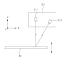
도 2는 본 발명에 따른 ATM 로봇의 블레이드 변형 감시 장치의 감시 방법을 갖는 감시 장치의 센서부를 나타내는 도면이다.
도 3은 본 발명에 따른 ATM 로봇의 블레이드 상에 형성되는 마크를 나타내는 도면이다.
도 4a 및 도 4b는 본 발명에 따른 블레이드의 이동 영역에 따른 ATM 로봇의 블레이드 변형을 감지하는 모습을 개략적으로 나타내는 도면이다.
도 5는 본 발명에 따른 ATM 로봇의 블레이드 변형 감시 장치의 감시 방법을 나타내는 순서도이다.1 is a block diagram showing a configuration of a monitoring apparatus having a monitoring method of a blade deformation monitoring apparatus of an ATM robot for wafer transfer according to the present invention.
2 is a view showing a sensor unit of a monitoring apparatus having a monitoring method of a blade deformation monitoring apparatus of an ATM robot according to the present invention.
3 is a view showing marks formed on a blade of an ATM robot according to the present invention.
FIGS. 4A and 4B are diagrams schematically showing the detection of the blade deformation of the ATM robot according to the moving region of the blade according to the present invention.
5 is a flowchart showing a monitoring method of a blade deformation monitoring apparatus of an ATM robot according to the present invention.
본 발명의 이점 및 특징, 그리고 그것들을 달성하는 방법은 첨부되는 도면과 함께 상세하게 후술되어 있는 실시예들을 참조하면 명확해질 것이다.BRIEF DESCRIPTION OF THE DRAWINGS The advantages and features of the present invention, and the manner of achieving them, will be apparent from and elucidated with reference to the embodiments described hereinafter in conjunction with the accompanying drawings.
그러나, 본 발명은 이하에서 개시되는 실시예들에 한정되는 것이 아니라 서로 다른 다양한 형태로 구현될 수 있으며, 단지 본 실시예들은 본 발명의 개시가 완전하도록 하고, 본 발명이 속하는 기술분야에서 통상의 지식을 가진 자에게 발명의 범주를 완전하게 알려주기 위해 제공되는 것이며, 본 발명은 청구항의 범주에 의해 정의될 뿐이다. 명세서 전체에 걸쳐 동일 참조 부호는 동일 구성 요소를 지칭한다.However, it is to be understood that the present invention is not limited to the disclosed embodiments, but may be embodied in many different forms and should not be construed as limited to the embodiments set forth herein. It is intended that the disclosure of the present invention be limited only by the terms of the appended claims. Like reference numerals refer to like elements throughout the specification.
본 발명의 실시예에 따른 웨이퍼 이송용 ATM 로봇의 블레이드 변형 감시 장치의 감시 방법을 설명하도록 한다.A monitoring method of the blade deformation monitoring apparatus of the ATM robot for wafer transfer according to the embodiment of the present invention will be described.
도 1은 본 발명에 따른 웨이퍼 이송용 ATM 로봇의 블레이드 변형 감시 장치의 감시 방법을 갖는 감시 장치의 구성을 나타내는 블록도이고, 도 2는 본 발명에 따른 ATM 로봇의 블레이드 변형 감시 장치의 감시 방법을 갖는 감시 장치의 센서부를 나타내는 도면이며, 도 3은 본 발명에 따른 ATM 로봇의 블레이드 상에 형성되는 마크를 나타내는 도면이고, 도 4a 및 도 4b는 본 발명에 따른 블레이드의 이동 영역에 따른 ATM 로봇의 블레이드 변형을 감지하는 모습을 개략적으로 나타내는 도면이며, 도 5는 본 발명에 따른 ATM 로봇의 블레이드 변형 감시 장치의 감시 방법을 나타내는 순서도인 바, 이를 바탕으로 설명한다.FIG. 1 is a block diagram showing the configuration of a monitoring apparatus having a monitoring method of a blade deformation monitoring apparatus for an ATM robot for transferring wafers according to the present invention, and FIG. 2 is a flowchart showing a monitoring method of a blade deformation monitoring apparatus for an ATM robot according to the present invention. FIG. 3 is a view showing a mark formed on a blade of an ATM robot according to the present invention, and FIGS. 4A and 4B are views showing a mark formed on the blade of the ATM robot according to the moving region of the blade according to the present invention. FIG. 5 is a flow chart showing a method of monitoring a blade deformation monitoring apparatus of an ATM robot according to the present invention, and will be described on the basis thereof.
본 실시예는 EFEM 설비(200)에서 웨이퍼를 로딩 및 언로딩하는 웨이퍼용 ATM(Atmosphere) 로봇의 블레이드(이하 블레이드, 50) 변형 감시 장치(이하 감시 장치, 100)을 이용한 감시 방법이다.The present embodiment is a monitoring method using a blade (hereinafter referred to as blade 50) deformation monitoring apparatus (hereinafter referred to as a monitoring apparatus) 100 of an ATM robot for a wafer for loading and unloading wafers in the
감시 장치(100)은, 센서부(110), 측정부(140), 산출부(150), 평가부(160)를 포함한다. 또한, 센서부(110), 측정부(140), 산출부(150), 평가부(160)에 전원을 공급하여 제어시키는 중앙제어부(170)를 더 포함할 수 있다.The
센서부(110)는 EFEM 설비(200)의 내측에 마련되어 블레이드(50)를 향해 빛을 조사하고 블레이드(50) 상에 반사광으로 형성된 마크를 감지한다.The
본 발명에서 마크는 센서부(110)에서 조사되는 빛을 통해 형성되는 반사광으로 설명된다.In the present invention, the mark is described as reflected light formed through the light emitted from the
센서부(110)는 광원으로서 레이저 다이오드(Laser diode, 111) 및, 광 수신부재인 촬상 카메라(113)를 포함할 수 있다.The
센서부(110)의 레이저 다이오드(Laser diode, 111)는 블레이드(50)에 빛을 조사하여 블레이드(50) 상에 반사광인 마크를 형성시킨다.A laser diode (111) of the sensor unit (110) irradiates the blade (50) with light to form a mark as a reflected light on the blade (50).
센서부(110)는 레이저 다이오드(111)로부터 블레이드 상으로 빛을 조사하여 블레이드(50) 상에 적어도 하나 이상 또는 다수개의 마크를 형성시키며, 이에 대한 구체적인 설명은 후술한다.The
센서부(110)의 촬상 카메라(113)는 레이저 다이오드(111)의 빛 조사를 통해 블레이드(50) 상에 형성된 마크를 감지하여 빛의 신호를 전기적인 신호로 변환시킨다.The
촬상 카메라(113)의 마크 감지는 블레이드(50)와 마크가 촬영된 이미지를 수득하여 수행된다.The mark detection of the
따라서, 센서부(110)는 레이저 다이오드(111)에서 조사된 빛을 통해 블레이드(50) 상에 마크를 형성시킨 후, 촬상 카메라(113)을 통해 수득되는 이미지 상에서 마크에 대한 기본 정보를 검출한다. 예컨대, 마크의 밝기 및 형상 중 적어도 어느 하나를 생성하여 촬상 카메라(113)를 통해 감지하는 역할을 수행한다.Therefore, the
촬상 카메라(113)에는 CCD(Charge coupled device, 전하 결합 소자) 또는 CIS(Contact image sensor, 저전력 촬상 소자) 등의 이미지 센서가 더 포함된다. The
촬상 카메라(113)는 블레이드(50) 상의 마크에 대한 기본 정보, 예컨대, 밝기의 강약을 통해 블레이드(50)의 변형 상태를 감지할 수 있도록 블레이드(50)의 이미지를 수득하여, 수득된 이미지 상에서의 마크의 위치인 화상 좌표를 생성할 수 있다.The
한편, EFEM 설비(200)의 내측에는 센서부(110)의 촬상 카메라(113)에 의해 생성된 블레이드(50)의 마크 정보를 디지털 신호로 변환시키는 증폭기(130)가 더 포함될 수 있다.The EFEM
증폭기(130)는 그 일단이 통신 인터페이스(120)와 연계되되, 센서부(110)에 의해 생성된 블레이드(50) 상의 마크 정보를 통신 인터페이스(120)의 입출력 과정으로 전달받아 디지털 신호로 출력시킨다.One end of the
증폭기(130)는 센서부(110)에 의해 감지된 블레이드(50)의 변형 상태를 디지털 데이터값으로 표출하여 중앙제어부(170)에 전송하기 때문에 블레이드(50) 상의 마크를 기반으로 한 블레이드(50)의 변형 이력을 실기간으로 확인가능하다.The
측정부(140)는 센서부(110)를 통해 생성된 마크의 이미지 상에서 기본 정보를 토대로 X, Y 및 Z 축으로 좌표화된 블레이드(50)의 이동 영역 내에서 마크의 위치 기준점을 미리 설정하며, 블레이드(50)의 이동 영역 내에서 블레이드(50) 상의 마크 위치를 좌표화시키는 역할을 한다.The
측정부(140)는 블레이드(50)의 이동 영역 내에 블레이드(50) 상의 마크를 일치시키기 위해 상대좌표 또는 절대좌표의 좌표계를 이용하여 블레이드(50) 상의 마크 위치에 대한 좌표 데이터를 생성시킨다.The
본 발명에서는 상기 블레이드(50)의 초기 구동시에 제1 화상 좌표를 측정하여 상기 마크의 위치 기준점을 미리 생성하고, 블레이드(50)의 초기 구동 이후에 블레이드(50) 상에서 마크의 위치에 대한 제2 화상 좌표를 측정한다. In the present invention, the first image coordinate is measured at the initial driving of the blade (50) to generate the position reference point of the mark in advance, and after the initial driving of the blade (50) The image coordinates are measured.
즉, 측정부(140)는 블레이드(50)의 이동 영역 내에서 블레이드(50) 상의 마크 위치를 좌표화시킴으로써, 복수회로 감지되는 블레이드(50)의 마크 위치에 대한 각각의 좌표 데이터가 생성되기 때문에 각 블레이드(50)의 변형 방향 이력을 검출할 수 있다.That is, the
산출부(150)는 블레이드(50)의 마크 위치에 대한 각각의 좌표 경로를 데이터화하되, 어느 하나의 좌표 데이터를 기준으로 미리 설정하며, 좌표 경로를 데이터화한 후에는 좌표 데이터 사이에 발생되는 오차를 계산하는 역할을 수행한다.The calculating
이때, 기준으로 미리 설정된 블레이드(50)의 마크 위치에 대한 좌표 데이터는, 측정부(140)에 의해 블레이드(50)의 성능에 문제가 발생되지 않은 범위 내로 검출된 좌표 데이터값일 수 있다.At this time, the coordinate data for the mark position of the
산출부(150)는 마크의 위치 기준점인 제1 화상 좌표와, 블레이드가 일정 공정을 수행한 후의 제2 화상 좌표 사이에 발생되는 오차에 대한 산출값을 생성시키며, 이러한 산출값을 토대로 블레이드(50)에 발생된 변형의 이력을 수식화한다.The
산출부(150)는 복수회로 감시되는 블레이드(50) 간에 기준이 되는 좌표 데이터값을 기반으로 하여 블레이드(50)의 변형에 대한 허용 범위를 생성할 수 있다.The calculating
산출부(150)에 의해 생성된 허용 범위는, 블레이드(50)가 웨이퍼를 로딩할 수 있는 최저 높이를 의미한다.The allowable range generated by the
즉, 허용 범위는 블레이드(50)의 성능에 문제가 발생하지 않은 범위로써, EFEM 설비(200)로부터 웨이퍼를 핸들링하는 최소한의 정상 작업이 가능한 블레이드(50)의 웨이퍼 로딩 높이를 의미하며, 그 값은 복수의 웨이퍼가 적치된 상태에 따라 가변적일 수 있다.That is, the allowable range means a wafer loading height of the
본 발명에서는 복수의 웨이퍼 중에 특정 웨이퍼를 로딩하기 위한 이웃하는 웨이퍼들 간의 높이로 결정될 수 있다.In the present invention, the height between neighboring wafers for loading a specific wafer into a plurality of wafers can be determined.
허용 범위는, 산출부(150)에 의해 기준으로 설정된 좌표 데이터값 및 변형이 없는 블레이드(정상 상태의 블레이드)의 허용 오차값을 이용하여 생성될 수 있다.The allowable range can be generated by using the coordinate data value set as a reference by the calculating
이때, 허용 오차값은 복수회로 감시된 블레이드(50)의 이력을 통해 산출된 블레이드(50)의 정상 변위이거나 또는 임의로 산출된 블레이드(50)의 정상 변위일 수 있다.At this time, the tolerance value may be the normal displacement of the
평가부(160)는 센서부(110), 측정부(140) 및 산출부(150)의 제어 과정을 거쳐 검출된 블레이드(50)의 마크 위치에 대한 좌표 데이터를 기반으로 블레이드(50)의 변형 방향 및 상태 등을 판별한다.The evaluating
이때, 평가부(160)는 블레이드(50)의 변형된 정도를 판별하기 위해 산출부(150)에 의해 생성 및 설정된 허용 범위를 이용한다.At this time, the evaluating
따라서, 평가부(160)는 좌표 데이터 사이에 발생되는 오차와 미리 설정된 허용 범위를 상호 비교하여 그 결과를 토대로 블레이드(50)의 변형 유무를 판별하는 역할을 수행한다.Accordingly, the evaluating
평가부(160)는 좌표 데이터 사이에 발생되는 오차가 미리 설정된 허용 범위를 벗어난 경우, 외부에서 인지되는 알림을 발생시키도록 알람수단(미도시)에 신호를 전송할 수 있다.The
알림수단은 평가부(160)와 연계되며, 산출부(150)에서 계산된 좌표 데이터 사이에 발생되는 오차가 미리 설정된 허용 범위를 벗어난 경우 알람을 발생시킬 수 있다.The notifying means may be associated with the evaluating
이때, 평가부(160)는 알람수단에서 알람이 발생하면, 블레이드(50)의 변형 상태를 비정상으로 판별하며, 평가부(160)의 판별을 기반으로 블레이드(50)의 변형 감시에 대한 이력이 중앙제어부(170)에 전송될 수 있다.At this time, when an alarm occurs in the alarm means, the
중앙제어부(170)는 전술한 센서부(110), 통신 인터페이스(120), 증폭기(130), 측정부(140), 산출부(150), 평가부(160)와 상호 연계되어 신호를 주고 받으며, 콘트롤러(180)를 매개로 각 신호 제어를 세밀하게 통제할 수 있다.The
전술한 감시 장치의 구성을 이용하여 블레이드의 변형 감시 방법을 구체적으로 설명한다. 단, 도면 상에 블레이드의 마크를 R1, R2로 도시하였지만, 이하에서는 블레이드의 마크 도면부호에 대한 지시를 생략한다.A method of monitoring the deformation of the blade using the configuration of the above-described monitoring apparatus will be described in detail. Although the marks of the blade are shown as R1 and R2 on the drawing, the following description of the marks of the blades is omitted.
더욱이, 본 실시예의 블레이드 변형은 처짐, 휨 및 비틀림 등을 포함하되, 블레이드의 길이 방향을 기준으로 하여 발생되는 종 방향 및 횡 방향의 변형을 토대로 설명하며, 변형 종류 및 변형 방향에 대해 한정하는 것은 아니다.Furthermore, the blade deformation of the present embodiment is explained based on deformation in the longitudinal direction and in the lateral direction, which is generated based on the longitudinal direction of the blade, including sagging, warping and twisting, no.
본 실시예의 감시 장치(100)을 이용한 감시 방법은, 유휴시간(Idle time, 반도체 제조공정 중 주변 설비가 가동 상태에서 실제로는 구동을 하고 있지 않는 시간)에 이루어질 수도 있으나 이에 한정되는 것은 아니다.The monitoring method using the
먼저, 블레이드(50)를 향해 빛을 조사하여 블레이드(50) 상에 마크를 형성시키는 단계를 진행한다(S10).First, a step of irradiating light toward the
센서부(110)는 광원인 레이저 다이오드(111)에서 조사된 빛을 통해 블레이드(50) 상에서 반사광으로 나타나는 마크를 형성시키고, 촬상 카메라(113)를 통해 블레이드(50) 상의 마크를 감지하여 형성된 마크에 대한 기본 정보를 포함하는 이미지를 획득한다.The
블레이드(50) 상에는 적어도 하나 이상의 마크가 형성되거나 또는 적어도 둘 이상의 마크가 형성되어 블레이드(50)의 변형을 구체적으로 판단하기 위한 정보로 활용된다.At least one mark is formed on the
이때, 블레이드(50)의 길이 방향을 기준으로 하여 종 방향 및 횡 방향 등과 같은 일방향의 변형 발생에 따라 센서부(110)를 통해 형성되는 블레이드(50)의 마크 수가 조절될 수 있다.At this time, the number of marks of the
예컨대, 블레이드(50) 상에 적어도 하나 이상의 마크가 형성될 경우, 센서부(110)의 빛 조사 각도 및 조사 위치에 의해 블레이드(50) 상에 형성될 마크의 위치가 정해지며, 마크의 형성 위치에 따라 블레이드(50)의 일방향 변형을 나타내는 기본 정보가 달라질 수 있다.For example, when at least one mark is formed on the
이때, 중앙제어부(170)는 블레이드(50) 상에 형성된 마크를 통해 변형의 발생 또는 미발생을 기반으로 한 총 두 가지 신호를 알리고 저장하도록 프로그래밍될 수 있다.At this time, the
블레이드(50) 상에 적어도 하나 이상의 마크를 형성함으로써, 마크의 기본 정보가 특정 방향으로 변형된 블레이드(50)에 대응하여 달라질 수 있으므로, 블레이드(50)의 변형 상태가 마크의 기본 정보를 통해 촬상 카메라(113)에 감지될 수 있다.By forming at least one mark on the
한편, 블레이드(50) 상에 적어도 둘 이상의 마크가 형성될 경우에는, 센서부(110)에 의해 블레이드(50) 상에 형성될 마크의 위치가 블레이드(50)의 폭방향으로 대칭되도록 정해질 수 있으며, 마크의 형성 위치에 따라 블레이드(50)의 일방향 변형을 나타내는 기본 정보가 달라질 수 있다.On the other hand, when at least two marks are formed on the
센서부(110)는 블레이드(50) 상에 형성된 적어도 둘 이상의 마크 중 어느 하나의 마크를 감지하거나 또는 모든 마크를 감지하여 변형이 상대적으로 더 발생된 블레이드(50)의 일단을 감시할 수 있다.The
이때, 중앙제어부(170)는 블레이드(50) 상에 형성된 각각의 마크를 통해 변형의 발생 또는 미발생을 기반으로 한 총 네 가지 신호를 알리고 저장하도록 프로그래밍될 수 있다.At this time, the
블레이드(50) 상에 적어도 둘 이상의 마크를 형성함으로써, 마크의 기본 정보가 특정 방향으로 변형된 블레이드(50)에 대응하여 달라질 수 있으므로, 블레이드(50)의 변형 상태가 마크의 기본 정보를 통해 센서부(110)의 촬상 카메라(113)에 감지될 수 있다.By forming at least two or more marks on the
구체적으로 블레이드(50)에 형성된 둘 이상의 마크를 감지하는 것은 둘 이상의 마크 중 어느 하나 또는 둘 이상의 마크의 위치에 대한 화상 좌표의 변화에 따라 블레이드(50)의 처짐, 뒤틀림을 구분되는 변형 상태를 감지할 수 있다.Specifically, sensing two or more marks formed on the
예컨대, 둘 이상의 마크 중에 하나의 마크의 화상 좌표가 변화되거나, 둘 이상의 마크 전체의 화상 좌표가 변화하는 것을 통해서 마크의 블레이드의 변형 상태를 감지할 수 있도록 한다.For example, it is possible to detect the deformation state of the blade of the mark by changing the image coordinates of one of the two or more marks or changing the image coordinates of the two or more marks.
상술한 본 발명은, 센서부(110)에 의해 블레이드(50) 상에 적어도 둘 이상의 마크를 형성하여 ATM 로봇의 작동 오류를 미연에 방지할 수 있다.The present invention can prevent an operation error of the ATM robot by forming at least two marks on the
구체적으로 도시하진 않았지만, ATM 로봇에는 조인트 구성을 갖는 두 개의 암(Arm)수단이 구동축과 면접촉으로 연결되어 어느 하나의 암수단이 블레이드(50)와 상호 결합될 수 있다.Although not shown in detail, two arm means having a joint configuration are connected to the drive shaft in surface contact with the ATM robot, so that one of the arm means can be coupled with the
이때, 블레이드(50)의 웨이퍼 핸들링 과정이 장시간 진행됨에 따라 블레이드(50)에 비틀림의 변형이 발생된 경우, 평가부(160)는 블레이드(50) 상에 형성된 각 마크를 토대로 블레이드(50)의 비틀림 변형에 따른 암수단의 구동 상에 분진 발생여부를 미리 판단하므로, 블레이드(50)의 일방향 변형이 실시간으로 판별가능하기 때문에 ATM 로봇의 작동 오류를 미연에 방지할 수 있다.If the
블레이드(50)에 발생된 특정 방향의 변형에 따라 마크의 기본 정보가 달라질 수 있으므로, 블레이드(50)의 변형에 따른 마크의 기본 정보 변화를 이력화하여 분석 자료로 활용할 수 있다.Since the basic information of the mark can be changed according to the deformation of the specific direction generated in the
본 실시예서는 블레이드(50) 상에 형성된 마크의 수를 적어도 하나 이상 또는 적어도 둘 이상으로 설명하였지만, 블레이드(50)의 어느 한 방향 또는 어느 복수 방향의 변형을 감지하기 위해 마크의 수를 추가로 증가시킬 수 있으며, 그 위치를 어느 하나로 한정하는 것은 아니다.Although the present embodiment has described at least one or more or at least two or more marks on the number of marks formed on the
블레이드(50) 상에 형성된 다수개의 마크는, 센서부(110)의 레이저 다이오드(111)에 의해 블레이드(50) 상에 조사되어 특정 패턴을 가진 채 정렬되거나 또는 임의로 정해진 위치에 각각 배치되며, 센서부(110)의 촬상 카메라(113)에 의해 촬영된 각 마크의 기본 정보가 중앙제어부(170)로 전송될 수 있다.The plurality of marks formed on the
또한, 블레이드(50)의 상에 다수개의 마크를 형성시키기 위해, 센서부(110)의 레이저 다이오드(111)가 듀얼(Dual) 조사식 등의 복수 조사식으로 구비될 수 있으며, 이에 대응하도록 센서부(110)의 촬상 카메라(113)가 하나 또는 복수로 구비되어 블레이드(50) 상의 마크를 촬영할 수 있다.In order to form a plurality of marks on the
한편, 본 실시예의 블레이드(50)가 다양한 규격의 웨이퍼를 로딩 및 언로딩하는 작업을 진행함에 따라 이에 대응하도록 블레이드(50) 상의 마크 형성 위치가 미리 설정가능하다.On the other hand, as the
예컨대, 센서부(110)의 촬상 카메라(113)를 통해 웨이퍼를 언로딩 중인 블레이드(50)의 전체 길이를 제 1 측정 정보로 생성하되, 웨이퍼를 로딩 중인 블레이드(50)에서 웨이퍼가 안착되지 않은 블레이드(50)의 내측 길이를 제 2 측정 정보로 생성할 수 있다.For example, the total length of the
블레이드(50)의 선단에는 제 1 측정 정보와 제 2 측정 정보의 상호 오차 정보를 기반으로 한 이격 공간이 형성될 수 있다.A separation space based on mutual error information between the first measurement information and the second measurement information may be formed at the tip of the
이격 공간은 블레이드(50)의 끝단으로부터 블레이드(50)의 내측 길이 방향을 향해 형성되며, 이로 인해, 블레이드(50)의 일단에는 오차 정보와 제 2 측정 정보 간을 구분하기 위한 경계부가 형성될 수 있다.The spacing space is formed toward the inner longitudinal direction of the
즉, 센서부(110)는 전술한 촬상 카메라(113)를 통해 이격 공간을 형성시키는 과정을 기반으로 하여 블레이드(50) 상의 마크가 경계부에서 일정 거리 떨어진 채 형성되도록 광원을 조사할 수 있다.That is, the
이때, 센서부(110)는 다양한 규격의 웨이퍼에 따라 블레이드(50)의 제 1 측정 정보 및 제 2 측정 정보가 달라지기 때문에 블레이드(50) 상에 형성되는 마크의 위치를 가변적으로 결정할 수 있다.At this time, since the first measurement information and the second measurement information of the
블레이드(50)에 마크를 형성시킨 이후에는 X, Y 및 Z 축 좌표로 설정된 블레이드(50)의 이동 영역 내에서 블레이드(50)의 마크 위치를 좌표화한 후 블레이드(50)의 마크 위치에 대한 각각의 좌표 데이터를 생성시키는 단계를 진행한다(S20).After the mark is formed on the
이때, 측정부(140)는 센서부(110)를 통해 획득된 이미지 내에서 마크의 기본 정보를 토대로 X, Y 및 Z 축으로 좌표화된 블레이드(50)의 이동 영역 내에서 마크의 제1 화상 좌표와 제2 화상 좌표를 산출하여 좌표 데이터를 생성한다.At this time, the measuring
본 발명에서 제1 화상 좌표와 제2 화상 좌표는 시계열 적인 순서에 따라 구분될 수 있으며, 이때 제1 화상 좌표는 블레이드(50)의 초기 구동시에 상기 블레이드(50)에 생성된 마크의 위치에 대한 위치 기준점으로 정의될 수 있다.In the present invention, the first image coordinate and the second image coordinate can be distinguished in a time series order, wherein the first image coordinate is obtained by dividing the position of the mark generated in the
제2 화상 좌표는 상기 블레이드(50)의 초기 구동 이후에 상기 블레이드에 생성된 마크의 위치에 대한 값으로 정의될 수 있다.The second image coordinate may be defined as a value for the position of the mark created on the blade after the initial drive of the
측정부(140)는 블레이드(50)의 이동 영역 내에 블레이드(50) 상의 마크를 일치시키기 위해 상대좌표 또는 절대좌표의 좌표계를 이용하여 블레이드(50) 상의 마크 위치 좌표를 검출할 수 있다.The
측정부(140)는 블레이드(50)의 이동 영역 내에 블레이드(50) 상의 마크 위치를 이미지를 수득하여 화상 좌표를 생성시킴으로써, 복수회로 감지되는 블레이드(50)의 마크 위치에 대한 각각의 좌표 데이터가 생성되기 때문에 블레이드(50)의 변형 방향 이력을 검출할 수 있다.The
블레이드(50)의 마크 위치를 좌표화시킨 이후에는, 마크에 대한 좌표 경로를 데이터화한 후 좌표 데이터를 토대로 기준이 되는 상기 제1 화상 좌표와 제2 화상 좌표에 발생되는 오차를 계산하는 단계를 진행한다(S30).After the mark position of the
이때, 산출부(150)는 블레이드(50)의 마크 위치에 대한 각각의 좌표 경로를 데이터화하되, 어느 하나의 좌표 데이터를 기준으로 미리 설정하며, 좌표 경로를 데이터화한 후에는 블레이드(50)의 좌표 데이터 사이에 발생되는 오차를 계산한다.At this time, the calculating
이때, 기준으로 미리 설정된 좌표 데이터는, 측정부(140)에 의해 블레이드(50)의 성능에 문제가 발생되지 않은 범위 내로 검출된 블레이드(50)의 좌표 데이터값일 수 있다.At this time, the coordinate data preset as the reference may be the coordinate data value of the
산출부(150)는 상기 좌표 데이터 사이에 발생되는 오차에 대한 산출값을 생성시키며, 이러한 산출값을 토대로 블레이드(50)에 발생된 변형의 이력을 수식화한다.The
산출부(150)는 복수회로 감시되는 블레이드(50) 간에 기준이 되는 좌표 데이터값을 기반으로 하여 블레이드(50)의 변형에 대한 허용 범위를 생성할 수 있다.The calculating
허용 범위는, 산출부(150)에 의해 기준으로 설정된 좌표 데이터값 및 변형이 없는 블레이드(정상 상태의 블레이드)의 허용 오차값을 이용하여 생성될 수 있다.The allowable range can be generated by using the coordinate data value set as a reference by the calculating
이때, 허용 오차값은 복수회로 감시된 블레이드(50)의 이력을 통해 도출된 블레이드(50)의 정상 변위이거나 또는 임의로 정해진 블레이드(50)의 정상 변위일 수 있다.At this time, the tolerance value may be the normal displacement of the
다음으로, 블레이드(50)의 마크 위치에 대한 좌표 데이터 사이에 발생되는 오차와 미리 설정된 허용 범위를 상호 비교하여 블레이드(50)의 변형 유무를 판별하는 단계를 진행한다(S40).Next, a step of discriminating whether or not the
이때, 평가부(160)는 센서부(110), 측정부(140) 및 산출부(150)의 각 제어 과정을 거쳐 검출된 좌표 데이터를 기반으로 블레이드(50)의 변형 방향 및 상태 등을 판별한다.At this time, the
평가부(160)는 블레이드(50)의 변형된 정도를 판별하기 위해 산출부(150)에 의해 생성 및 설정된 허용 범위를 이용한다.The evaluating
평가부(160)는 좌표 데이터 사이에 발생되는 오차가 미리 설정된 허용 범위를 벗어난 경우, 외부에서 인지되는 알림을 발생시키도록 알람수단(미도시)에 신호를 전송할 수 있다.The
평가부(160)를 통해 알림이 발생된 경우, 블레이드(50)의 점검을 진행한 후 전술한 S10 단계로 되돌아가 블레이드(50)의 변형을 감시할 수 있다.When the notification is generated through the
평가부(160)에 의해 블레이드(50)의 변형 유무를 실시간으로 판별함으로써, 웨이퍼를 핸들링하는 ATM 로봇의 작동 오류를 미리 감지하고 그 원인을 예방할 수 있다.By evaluating whether the
특히, 센서부(110)를 통해 블레이드(50) 상에 적어도 둘 이상의 마크를 형성시킬 경우 ATM 로봇의 작동 오류를 미리 감지가능하다.Particularly, when at least two marks are formed on the
ATM 로봇에는 조인트 구성을 갖는 두 개의 암(Arm)수단이 구동축과 면접촉으로 연계되어 어느 하나의 암수단이 블레이드(50)와 상호 결합될 수 있다.Two arm means having a joint configuration are connected to the drive shaft in surface contact with the ATM robot so that one arm means can be mutually coupled with the
그리고 평가부(160)은 상기 블레이드 상에 적어도 둘 이상의 마크가 형성되면, 상기 적어도 둘 이상의 마크 중 어느 하나의 화상 좌표가 변화되거나, 둘 이상의 화상 좌표가 변화되는 경우, 상기 화상 좌표의 변화량을 검출하여 상기 블레이드의 변형 상태를 판단할 수 있다.When at least two or more marks are formed on the blade and the image coordinates of any one of the at least two marks changes, or when two or more image coordinates change, the
구체적으로 블레이드(50)의 웨이퍼 핸들링 과정이 장시간 진행됨에 따라 블레이드(50)에 비틀림의 변형이 발생된 경우, 평가부(160)는 블레이드(50) 상에 적어도 둘 이상으로 형성된 마크를 토대로 ATM 로봇의 암수단에 발생된 비틀림의 변형으로 인한 분진 발생여부를 미리 판단가능하므로, 실시간으로 블레이드(50)의 변형에 따른 ATM 로봇의 작동 오류를 방지할 수 있어서, 공정상에 고가의 웨이퍼를 손상시키는 것을 방지할 수 있다.Specifically, when the
이하, 본 실시예를 통하여 블레이드의 변형 판별 결과가 도출되는 과정을 보다 상세하게 설명한다.Hereinafter, the process of deriving the result of deformation determination of the blade will be described in more detail with reference to this embodiment.
다만, 하기의 실시예는 본 발명을 구체적으로 설명하기 위한 일실시예에 불과할 뿐, 본 발명의 권리 범위를 이에 한정하지 않는다.It should be noted, however, that the following examples are for illustrative purposes only and are not intended to limit the scope of the present invention.
<실시예><Examples>
본 실시예는, 센서부에 의해 광원을 조사하여 블레이드 상에 적어도 둘 이상의 마크를 형성시키되, 블레이드의 마크 위치에 대한 좌표 데이터 사이에 발생되는 오차와 미리 설정된 블레이드의 변형 허용 범위를 상호 비교하여 블레이드의 변형 판별 과정을 진행한다.In this embodiment, at least two marks are formed on the blade by irradiating the light source with the sensor unit, and the error generated between the coordinate data of the mark position of the blade and the deformation tolerance range of the predetermined blade are compared with each other, .
단, 표 1은 블레이드 변형 판별 결과를 나타내고, X, Y 및 Z축 좌표는 미리 설정된 블레이드의 이동 영역이며, 복수회로 감지되는 블레이드의 도면부호를 모두 동일하게 지시한다.Table 1 shows the results of the blade deformation determination, and the X, Y, and Z axis coordinates indicate the predetermined moving region of the blade, and indicate the same reference numerals of the blades to be sensed in a plurality of circuits.
또한, 블레이드의 변형 허용 범위는, 마크의 수에 따른 T1-X < P1 < T1+X 및 T2-X < P2 < T2+X 이고, T1 및 T2는 기준이 되는 좌표 데이터값이며, P1, P2는 좌표 데이터 사이에 발생된 오차(이하, 데이터 오차)의 산출값이고, X는 미리 설정된 허용 오차값이다.The deformation allowable range of the blade is T1-X <P1 <T1 + X and T2-X <P2 <T2 + X according to the number of marks, T1 and T2 are coordinate data values for reference, P1 and P2 (Hereinafter referred to as data error) generated between coordinate data, and X is a predetermined tolerance value.
한편, 본 실시예는, T1 및 T2가 각각 10 및 X가 5이며, 미리 설정된 블레이드의 변형 허용 범위를 마크의 수에 따른 5 < P1 < 15 및 5 < P2 < 15로 정한다.On the other hand, in the present embodiment, T1 and T2 are respectively 10 and X is 5, and 5 < P1 < 15 and 5 < P2 <

표 1에서 알 수 있듯이, 비교예 A 내지 C는 블레이드(50)의 변형 판별 결과 비정상으로써, 블레이드(50)에 변형이 발생하여 ATM 로봇에 대한 점검이 필요한 경우이다.As can be seen from Table 1, the comparative examples A to C are cases where the
반면에, 실험예 A 및 실험예 B는 블레이드(50)의 변형 판별 결과 정상으로써, ATM 로봇이 올바르게 작동되는 경우이다.On the other hand, in Experimental Example A and Experimental Example B, it is normal that the ATM robot is correctly operated as a result of deformation discrimination of the
구체적으로 설명하자면, 비교예 A는, 데이터 오차 P1의 산출값이 9이고, 데이터 오차 P2의 산출값이 3인 경우이다.To be more specific, Comparative Example A is a case where the calculated value of the data error P1 is 9 and the calculated value of the data error P2 is 3.
비교예 A에서, 블레이드(50)는 데이터 오차 P1의 산출값이 허용 범위 내에 포함되나 데이터 오차 P2의 산출값이 허용 범위를 벗어나기 때문에 변형 판별 결과 비정상으로 도출된다.In Comparative Example A, the
비교예 B는, 데이터 오차 P1의 산출값이 1이고, 데이터 오차 P2의 산출값이 8인 경우이다.Comparative Example B is a case where the calculated value of the data error P1 is 1 and the calculated value of the data error P2 is 8.
비교예 B에서, 블레이드(50)는 데이터 오차 P2가 허용 범위 내에 포함되나 데이터 오차 P1이 허용 범위를 벗어나기 때문에 변형 판별 결과 비정상으로 도출된다.In the comparative example B, the
비교예 C는, 데이터 오차 P1의 산출값이 4이고, 데이터 오차 P2의 산출값이 17인 경우이다.In Comparative Example C, the calculated value of the data error P1 is 4 and the calculated value of the data error P2 is 17.
비교예 C에서, 블레이드(50)는 데이터 오차 P1 및 P2가 모두 허용 범위를 벗어나기 때문에 변형 판단 결과 비정상으로 도출된다.In the comparative example C, since the data errors P1 and P2 are both out of the permissible range, the
이때, 비교예 A 및 비교예 B의 블레이드(50)는, 각 블레이드(50)의 길이 방향과 교차되는 횡 방향으로의 변형이 주로 발생된 경우로 판별될 수 있다.At this time, the
또한, 비교예 C의 블레이드(50)는, 길이 방향에 따른 종 방향 및 길이 방향에 교차되는 횡 방향으로의 변형이 주로 발생된 경우로 판별될 수 있다.In addition, the
실험예 A는, 데이터 오차 P1의 산출값이 9이고, 데이터 오차 P2의 산출값이 8인 경우이다.Experimental example A is a case where the calculated value of the data error P1 is 9 and the calculated value of the data error P2 is 8.
실험예 A에서, 블레이드(50)는 데이터 오차 P1 및 P2가 모두 허용 범위에 포함되기 때문에 변형 판별 결과 정상으로 도출된다.In Experimental Example A, the
실험예 B는, 데이터 오차 P1의 산출값이 10이고, 데이터 오차 P2의 산출값이 10인 경우이다.In Experiment B, the calculated value of the data error P1 is 10 and the calculated value of the data error P2 is 10.
실험예 B에서, 블레이드(50)는 데이터 오차 P1 및 P2가 모두 허용 범위에 포함되기 때문에 변형 판별 결과 정상으로 도출된다.In Experimental Example B, since the data errors P1 and P2 are both included in the allowable range, the
실험예 A에서의 블레이드(50)는 변형 판별 결과 허용 범위 내에 포함되지만, 실험예 B에서의 블레이드(50)보다 어느 한 방향으로 변형이 발생된 경우이므로, 실험예 B의 블레이드(50)를 통해 웨이퍼의 핸들링이 올바르게 진행되고 있음을 알 수 있다.Since the
한편, 평가부(160)에 의해 블레이드(50)의 마크 위치에 대한 좌표 데이터 사이에 발생되는 오차와 미리 설정된 허용 범위를 상호 비교하여 블레이드(50)의 변형 유무가 판별된 후, 감시된 블레이드(50) 변형 판단의 결과를 기록 및 저장할 수 있다.On the other hand, after the
블레이드(50)의 변형 결과에 대한 기록 및 저장된 정보는, 예상치 못한 반도체 제조 공정 상의 사고, 예컨대, 블레이드(50) 변형으로 인한 웨이퍼의 이송 에러 또는 블레이드(50)의 과부하로 인한 전체 공정 지연 등을 미리 예방하기 위한 블레이드(50) 상태 표준화(기준화)의 주요 자료가 될 수 있다.The recorded and stored information about the result of the deformation of the
본 발명이 속하는 기술분야의 통상의 지식을 가진 자는 본 발명이 그 기술적 사상이나 필수적인 특징을 변경하지 않고서 다른 구체적인 형태로 실시될 수 있다는 것을 이해할 수 있을 것이다. 그러므로, 이상에서 기술한 실시예들은 모든 면에서 예시적인 것이며 한정적이 아닌 것으로 이해해야만 한다. 본 발명의 범위는 상기 상세한 설명보다는 후술하는 특허청구의 범위에 의하여 나타내어지며, 특허청구의 범위의 의미 및 범위 그리고 그 균등 개념으로부터 도출되는 모든 변경 또는 변형된 형태가 본 발명의 범위에 포함되는 것으로 해석되어야 한다.It will be understood by those skilled in the art that the present invention may be embodied in other specific forms without departing from the spirit or essential characteristics thereof. Therefore, it should be understood that the above-described embodiments are illustrative in all aspects and not restrictive. The scope of the present invention is defined by the appended claims rather than the foregoing detailed description, and all changes or modifications derived from the meaning and scope of the claims and the equivalents thereof are included in the scope of the present invention Should be interpreted.
50: ATM(Atmosphere) 로봇의 블레이드
100: ATM 로봇의 블레이드 변형 감시 장치
110: 센서부
111: 레이저 다이오드(Laser diode)
113: 촬상 카메라
120: 통신 인터페이스
130: 증폭기
140: 측정부
150: 산출부
160: 평가부
170: 중앙제어부
180: 콘트롤러
200: EFEM(Equipment front end module) 설비50: ATM (Atmosphere) Robot's blade
100: Blade deformation monitoring device of ATM robot
110: sensor part 111: laser diode (laser diode)
113: imaging camera 120: communication interface
130: amplifier 140:
150: Calculator 160:
170: central control unit 180: controller
200: EFEM (Equipment front end module) facility
Claims (6)
(a) 센서부가 광원으로부터 빛을 조사하여 상기 블레이드 상에 반사광으로 나타나는 적어도 하나 이상의 마크가 생성되는 단계;
(b) 측정부가 상기 블레이드의 초기 구동시에 상기 블레이드에 생성된 마크의 위치에 대한 제1 화상 좌표를 측정하여 위치 기준점이 생성되고, 상기 블레이드의 초기 구동 이후에 상기 블레이드에 생성된 마크의 위치에 대한 제2 화상 좌표를 측정하여 좌표 데이터가 생성되는 단계;
(c) 산출부가 상기 마크의 위치에 대한 좌표 데이터를 토대로 상기 제1 화상 좌표와 제2 화상 좌표 사이에 발생되는 오차를 계산하는 단계; 및
(d) 평가부가 상기 좌표 데이터 사이에 발생되는 오차와 미리 설정된 상기 블레이드의 변형 허용 범위를 상호 비교하여 변형 유무를 판별하는 단계;
를 포함하는 것을 특징으로 하는 웨이퍼 이송용 ATM 로봇의 블레이드 변형 감시 장치의 감시 방법.
A monitoring method of an ATM (Atmosphere) robot blade deformation monitoring apparatus for loading and unloading wafers to an equipment front end module (EFEM)
(a) irradiating light from a sensor unit light source to generate at least one mark appearing as reflected light on the blade;
(b) measuring a first image coordinate with respect to a position of a mark generated on the blade at the initial driving of the blade, thereby generating a position reference point, and after the initial driving of the blade, Measuring coordinates of the second image to generate coordinate data;
(c) calculating an error generated between the first image coordinate and the second image coordinate based on the coordinate data of the position of the mark by the calculating unit; And
(d) comparing the error generated between the coordinate data and the predetermined tolerance range of the blade to determine whether the blade is deformed;
And monitoring the blade deformation monitoring device of the ATM robot for wafer transfer.
상기 마크는 상기 블레이드 상에 적어도 둘 이상으로 형성되되,
상기 블레이드의 변형에 대응되는 상기 각 마크에 대한 화상 좌표의 변화를 통해 상기 블레이드의 변형에 의한 분진 발생을 감지하는 것을 특징으로 하는 웨이퍼 이송용 ATM 로봇의 블레이드 변형 감시 장치의 감시 방법.
The method according to claim 1,
Wherein the mark is formed on the blade at least two or more,
And detecting generation of dust due to deformation of the blade through change in image coordinates of the mark corresponding to deformation of the blade.
상기 각 마크에 대한 화상 좌표는 마크의 밝기 및 형상 중 적어도 어느 하나로 생성되는 것을 특징으로 하는 웨이퍼 이송용 ATM 로봇의 블레이드 변형 감시 장치의 감시 방법.
3. The method of claim 2,
Wherein the image coordinate for each mark is generated by at least one of brightness and shape of the mark.
상기 (c) 단계에서, 상기 블레이드의 변형 허용 범위는 상기 블레이드가 웨이퍼를 로딩할 수 있는 최저 높이인 것을 특징으로 하는 웨이퍼 이송용 ATM 로봇의 블레이드 변형 감시 장치의 감시 방법.
The method according to claim 1,
Wherein in the step (c), the deformation allowable range of the blade is the lowest height at which the blade can load the wafer.
상기 (d) 단계에서, 상기 마크의 위치에 대한 좌표 데이터 사이에 발생되는 오차가 설정된 상기 블레이드의 변형 허용 범위를 벗어난 경우, 외부에서 인지되도록 알림을 발생시키는 것을 특징으로 하는 웨이퍼 이송용 ATM 로봇의 블레이드 변형 감시 장치의 감시 방법.
The method according to claim 1,
Wherein in the step (d), when an error occurring between the coordinate data of the position of the mark is out of a set tolerance range of the blade, the notification is generated so as to be recognized from outside. Monitoring method of blade deformation monitoring apparatus.
EFEM 설비 내에 구비되되, 빛을 조사하여 상기 블레이드 상에 반사광으로 나타나는 적어도 하나 이상의 마크를 생성시키기 위한 레이저 다이오드 및 상기 블레이드 상의 마크를 촬상하여 상기 마크의 화상 좌표를 생성하기 위한 촬상 카메라를 포함하는 센서부; 및
상기 센서부와 상호 연계되어 신호를 주고 받는 것으로, 상기 블레이드의 초기 구동시에 제1 화상 좌표를 측정하여 상기 마크의 위치 기준점을 미리 생성하고, 상기 블레이드의 초기 구동 이후에 상기 마크의 위치에 대한 제2 화상 좌표를 측정하여 좌표 데이터로 생성시키는 측정부와, 상기 마크의 위치에 대한 좌표 데이터를 토대로 상기 제1 화상 좌표와 제2 화상 좌표 사이에 발생되는 오차를 계산하는 산출부 및, 상기 좌표 데이터 사이에 발생되는 오차와 미리 설정된 상기 블레이드의 변형 허용 범위를 상호 비교하여 변형 유무를 판별하는 평가부를 포함하는 중앙제어부;
를 포함하는 것을 특징으로 하는 웨이퍼 이송용 ATM 로봇의 블레이드 변형 감시 장치.1. A blade deformation monitoring apparatus for an ATM robot for wafer transfer,
A sensor comprising a laser diode for generating at least one mark appearing as reflected light on the blade by irradiating light to the EFEM facility and an imaging camera for imaging the mark on the blade to generate image coordinates of the mark, part; And
And a controller for controlling the position of the mark on the basis of the position of the mark after the initial driving of the blade, A calculating unit for calculating an error to be generated between the first image coordinate and the second image coordinate based on the coordinate data for the position of the mark; And an evaluation unit for determining whether or not the blade is deformed by comparing an error generated between the blade and the predetermined allowable range of the blade;
And a controller for monitoring the blade deformation of the ATM robot for wafer transfer.
Priority Applications (1)
| Application Number | Priority Date | Filing Date | Title |
|---|---|---|---|
| KR1020170024670A KR20180098432A (en) | 2017-02-24 | 2017-02-24 | Method for blade strain monitoring device of atmosphere robot for wafer transporting |
Applications Claiming Priority (1)
| Application Number | Priority Date | Filing Date | Title |
|---|---|---|---|
| KR1020170024670A KR20180098432A (en) | 2017-02-24 | 2017-02-24 | Method for blade strain monitoring device of atmosphere robot for wafer transporting |
Publications (1)
| Publication Number | Publication Date |
|---|---|
| KR20180098432A true KR20180098432A (en) | 2018-09-04 |
Family
ID=63598259
Family Applications (1)
| Application Number | Title | Priority Date | Filing Date |
|---|---|---|---|
| KR1020170024670A Ceased KR20180098432A (en) | 2017-02-24 | 2017-02-24 | Method for blade strain monitoring device of atmosphere robot for wafer transporting |
Country Status (1)
| Country | Link |
|---|---|
| KR (1) | KR20180098432A (en) |
-
2017
- 2017-02-24 KR KR1020170024670A patent/KR20180098432A/en not_active Ceased
Similar Documents
| Publication | Publication Date | Title |
|---|---|---|
| EP3618980B1 (en) | Methods and systems for improved quality inspection of products using a robot | |
| KR102172266B1 (en) | Board Transfer Hand Diagnosis System | |
| US11837484B2 (en) | Robot arm device and method for transferring wafer | |
| US20250149362A1 (en) | Wafer processing systems, wafer transport devices, and related methods | |
| US20220333922A1 (en) | Deterioration determination apparatus, deterioration determination method, and computer-readable storage medium storing a control program | |
| JP2013515959A (en) | System and method for runtime determination of camera miscalibration | |
| US20100234992A1 (en) | Semiconductor wafer robot alignment system and method | |
| CN105514010A (en) | Method for safely transferring silicon chips | |
| US20030128024A1 (en) | Apparatus for recognizing working position of device transfer system in semiconductor device test handler and method thereof | |
| CN105470178B (en) | Optimize the method for silicon wafer carrying device maintenance period | |
| CN117080139B (en) | Wafer conveying control method and conveying control system based on vacuum adsorption technology | |
| JP6424560B2 (en) | Abnormality cause estimation device, picking device, and abnormality cause estimation method in picking device | |
| CN118571773A (en) | Wafer status detection method, device, equipment and medium | |
| CN120521489A (en) | Aircraft engine blade detection method, system and equipment | |
| KR20180098432A (en) | Method for blade strain monitoring device of atmosphere robot for wafer transporting | |
| US20080204764A1 (en) | Lead terminal inspection method and lead terminal inspection apparatus | |
| CN118608316A (en) | A semiconductor device image data detection system and method based on artificial intelligence | |
| US12269694B2 (en) | Controller | |
| KR101952840B1 (en) | System and Method for Detecting Degradation Trend of Arm Blade for Wafer Transfer Robot | |
| KR101089593B1 (en) | Wafer prober station and its control method that complements the mechanical rigidity of the chuck | |
| US20240238973A1 (en) | Tool check device, tool check program, and tool check method for robot arm | |
| CN111906043B (en) | Pose detection method and system | |
| US20210285999A1 (en) | Electronic component handling apparatus and electronic component testing apparatus | |
| KR102573339B1 (en) | Apparatus for picking up semiconductor devices and method of controlling operations of the same | |
| CN115958586A (en) | Component abnormality monitoring method, electronic device, and storage medium |
Legal Events
| Date | Code | Title | Description |
|---|---|---|---|
| A201 | Request for examination | ||
| PA0109 | Patent application |
St.27 status event code: A-0-1-A10-A12-nap-PA0109 |
|
| PA0201 | Request for examination |
St.27 status event code: A-1-2-D10-D11-exm-PA0201 |
|
| D13-X000 | Search requested |
St.27 status event code: A-1-2-D10-D13-srh-X000 |
|
| D14-X000 | Search report completed |
St.27 status event code: A-1-2-D10-D14-srh-X000 |
|
| E902 | Notification of reason for refusal | ||
| PE0902 | Notice of grounds for rejection |
St.27 status event code: A-1-2-D10-D21-exm-PE0902 |
|
| E13-X000 | Pre-grant limitation requested |
St.27 status event code: A-2-3-E10-E13-lim-X000 |
|
| P11-X000 | Amendment of application requested |
St.27 status event code: A-2-2-P10-P11-nap-X000 |
|
| P13-X000 | Application amended |
St.27 status event code: A-2-2-P10-P13-nap-X000 |
|
| PG1501 | Laying open of application |
St.27 status event code: A-1-1-Q10-Q12-nap-PG1501 |
|
| E902 | Notification of reason for refusal | ||
| PE0902 | Notice of grounds for rejection |
St.27 status event code: A-1-2-D10-D21-exm-PE0902 |
|
| E601 | Decision to refuse application | ||
| PE0601 | Decision on rejection of patent |
St.27 status event code: N-2-6-B10-B15-exm-PE0601 |
|
| P22-X000 | Classification modified |
St.27 status event code: A-2-2-P10-P22-nap-X000 |