KR20180098406A - Voltage reactive power control device and recording medium - Google Patents
Voltage reactive power control device and recording medium Download PDFInfo
- Publication number
- KR20180098406A KR20180098406A KR1020187022837A KR20187022837A KR20180098406A KR 20180098406 A KR20180098406 A KR 20180098406A KR 1020187022837 A KR1020187022837 A KR 1020187022837A KR 20187022837 A KR20187022837 A KR 20187022837A KR 20180098406 A KR20180098406 A KR 20180098406A
- Authority
- KR
- South Korea
- Prior art keywords
- variation
- voltage
- fluctuation
- bus
- line voltage
- Prior art date
- Legal status (The legal status is an assumption and is not a legal conclusion. Google has not performed a legal analysis and makes no representation as to the accuracy of the status listed.)
- Granted
Links
Images


Classifications
-
- H—ELECTRICITY
- H02—GENERATION; CONVERSION OR DISTRIBUTION OF ELECTRIC POWER
- H02J—ELECTRIC POWER NETWORKS; CIRCUIT ARRANGEMENTS OR SYSTEMS FOR SUPPLYING OR DISTRIBUTING ELECTRIC POWER; SYSTEMS FOR STORING ELECTRIC ENERGY
- H02J3/00—Circuit arrangements for AC mains or AC distribution networks
- H02J3/12—Arrangements for adjusting voltage in AC networks by changing a characteristic of the network load
- H02J3/16—Arrangements for adjusting voltage in AC networks by changing a characteristic of the network load by adjustment of reactive power
-
- H—ELECTRICITY
- H02—GENERATION; CONVERSION OR DISTRIBUTION OF ELECTRIC POWER
- H02J—ELECTRIC POWER NETWORKS; CIRCUIT ARRANGEMENTS OR SYSTEMS FOR SUPPLYING OR DISTRIBUTING ELECTRIC POWER; SYSTEMS FOR STORING ELECTRIC ENERGY
- H02J3/00—Circuit arrangements for AC mains or AC distribution networks
- H02J3/18—Arrangements for adjusting, eliminating or compensating reactive power in networks
- H02J3/1878—Arrangements for adjusting, eliminating or compensating reactive power in networks using tap changing or phase shifting transformers
-
- H—ELECTRICITY
- H02—GENERATION; CONVERSION OR DISTRIBUTION OF ELECTRIC POWER
- H02J—ELECTRIC POWER NETWORKS; CIRCUIT ARRANGEMENTS OR SYSTEMS FOR SUPPLYING OR DISTRIBUTING ELECTRIC POWER; SYSTEMS FOR STORING ELECTRIC ENERGY
- H02J3/00—Circuit arrangements for AC mains or AC distribution networks
- H02J3/28—Arrangements for balancing of the load in networks by storage of energy
- H02J3/32—Arrangements for balancing of the load in networks by storage of energy using batteries or super capacitors with converting means
-
- H—ELECTRICITY
- H02—GENERATION; CONVERSION OR DISTRIBUTION OF ELECTRIC POWER
- H02J—ELECTRIC POWER NETWORKS; CIRCUIT ARRANGEMENTS OR SYSTEMS FOR SUPPLYING OR DISTRIBUTING ELECTRIC POWER; SYSTEMS FOR STORING ELECTRIC ENERGY
- H02J3/00—Circuit arrangements for AC mains or AC distribution networks
- H02J3/38—Arrangements for feeding a single network from two or more generators or sources in parallel; Arrangements for feeding already energised networks from additional generators or sources in parallel
- H02J3/381—Dispersed generators
-
- H02J3/382—
-
- H—ELECTRICITY
- H02—GENERATION; CONVERSION OR DISTRIBUTION OF ELECTRIC POWER
- H02J—ELECTRIC POWER NETWORKS; CIRCUIT ARRANGEMENTS OR SYSTEMS FOR SUPPLYING OR DISTRIBUTING ELECTRIC POWER; SYSTEMS FOR STORING ELECTRIC ENERGY
- H02J3/00—Circuit arrangements for AC mains or AC distribution networks
- H02J3/38—Arrangements for feeding a single network from two or more generators or sources in parallel; Arrangements for feeding already energised networks from additional generators or sources in parallel
- H02J3/46—Controlling the sharing of generated power between the generators, sources or networks
- H02J3/50—Controlling the sharing of reactive power
-
- G—PHYSICS
- G05—CONTROLLING; REGULATING
- G05F—SYSTEMS FOR REGULATING ELECTRIC OR MAGNETIC VARIABLES
- G05F1/00—Automatic systems in which deviations of an electric quantity from one or more predetermined values are detected at the output of the system and fed back to a device within the system to restore the detected quantity to its predetermined value or values, i.e. retroactive systems
- G05F1/70—Regulating power factor; Regulating reactive current or power
-
- H—ELECTRICITY
- H02—GENERATION; CONVERSION OR DISTRIBUTION OF ELECTRIC POWER
- H02J—ELECTRIC POWER NETWORKS; CIRCUIT ARRANGEMENTS OR SYSTEMS FOR SUPPLYING OR DISTRIBUTING ELECTRIC POWER; SYSTEMS FOR STORING ELECTRIC ENERGY
- H02J2101/00—Supply or distribution of decentralised, dispersed or local electric power generation
- H02J2101/20—Dispersed power generation using renewable energy sources
-
- H—ELECTRICITY
- H02—GENERATION; CONVERSION OR DISTRIBUTION OF ELECTRIC POWER
- H02J—ELECTRIC POWER NETWORKS; CIRCUIT ARRANGEMENTS OR SYSTEMS FOR SUPPLYING OR DISTRIBUTING ELECTRIC POWER; SYSTEMS FOR STORING ELECTRIC ENERGY
- H02J7/00—Circuit arrangements for charging or discharging batteries or for supplying loads from batteries
- H02J7/34—Parallel operation in networks using both storage and other DC sources, e.g. providing buffering
- H02J7/35—Parallel operation in networks using both storage and other DC sources, e.g. providing buffering with light sensitive cells
-
- Y—GENERAL TAGGING OF NEW TECHNOLOGICAL DEVELOPMENTS; GENERAL TAGGING OF CROSS-SECTIONAL TECHNOLOGIES SPANNING OVER SEVERAL SECTIONS OF THE IPC; TECHNICAL SUBJECTS COVERED BY FORMER USPC CROSS-REFERENCE ART COLLECTIONS [XRACs] AND DIGESTS
- Y02—TECHNOLOGIES OR APPLICATIONS FOR MITIGATION OR ADAPTATION AGAINST CLIMATE CHANGE
- Y02E—REDUCTION OF GREENHOUSE GAS [GHG] EMISSIONS, RELATED TO ENERGY GENERATION, TRANSMISSION OR DISTRIBUTION
- Y02E10/00—Energy generation through renewable energy sources
- Y02E10/50—Photovoltaic [PV] energy
- Y02E10/56—Power conversion systems, e.g. maximum power point trackers
-
- Y—GENERAL TAGGING OF NEW TECHNOLOGICAL DEVELOPMENTS; GENERAL TAGGING OF CROSS-SECTIONAL TECHNOLOGIES SPANNING OVER SEVERAL SECTIONS OF THE IPC; TECHNICAL SUBJECTS COVERED BY FORMER USPC CROSS-REFERENCE ART COLLECTIONS [XRACs] AND DIGESTS
- Y02—TECHNOLOGIES OR APPLICATIONS FOR MITIGATION OR ADAPTATION AGAINST CLIMATE CHANGE
- Y02E—REDUCTION OF GREENHOUSE GAS [GHG] EMISSIONS, RELATED TO ENERGY GENERATION, TRANSMISSION OR DISTRIBUTION
- Y02E10/00—Energy generation through renewable energy sources
- Y02E10/70—Wind energy
- Y02E10/76—Power conversion electric or electronic aspects
-
- Y—GENERAL TAGGING OF NEW TECHNOLOGICAL DEVELOPMENTS; GENERAL TAGGING OF CROSS-SECTIONAL TECHNOLOGIES SPANNING OVER SEVERAL SECTIONS OF THE IPC; TECHNICAL SUBJECTS COVERED BY FORMER USPC CROSS-REFERENCE ART COLLECTIONS [XRACs] AND DIGESTS
- Y02—TECHNOLOGIES OR APPLICATIONS FOR MITIGATION OR ADAPTATION AGAINST CLIMATE CHANGE
- Y02E—REDUCTION OF GREENHOUSE GAS [GHG] EMISSIONS, RELATED TO ENERGY GENERATION, TRANSMISSION OR DISTRIBUTION
- Y02E40/00—Technologies for an efficient electrical power generation, transmission or distribution
- Y02E40/30—Reactive power compensation
-
- Y—GENERAL TAGGING OF NEW TECHNOLOGICAL DEVELOPMENTS; GENERAL TAGGING OF CROSS-SECTIONAL TECHNOLOGIES SPANNING OVER SEVERAL SECTIONS OF THE IPC; TECHNICAL SUBJECTS COVERED BY FORMER USPC CROSS-REFERENCE ART COLLECTIONS [XRACs] AND DIGESTS
- Y02—TECHNOLOGIES OR APPLICATIONS FOR MITIGATION OR ADAPTATION AGAINST CLIMATE CHANGE
- Y02E—REDUCTION OF GREENHOUSE GAS [GHG] EMISSIONS, RELATED TO ENERGY GENERATION, TRANSMISSION OR DISTRIBUTION
- Y02E70/00—Other energy conversion or management systems reducing GHG emissions
- Y02E70/30—Systems combining energy storage with energy generation of non-fossil origin
-
- Y—GENERAL TAGGING OF NEW TECHNOLOGICAL DEVELOPMENTS; GENERAL TAGGING OF CROSS-SECTIONAL TECHNOLOGIES SPANNING OVER SEVERAL SECTIONS OF THE IPC; TECHNICAL SUBJECTS COVERED BY FORMER USPC CROSS-REFERENCE ART COLLECTIONS [XRACs] AND DIGESTS
- Y02—TECHNOLOGIES OR APPLICATIONS FOR MITIGATION OR ADAPTATION AGAINST CLIMATE CHANGE
- Y02P—CLIMATE CHANGE MITIGATION TECHNOLOGIES IN THE PRODUCTION OR PROCESSING OF GOODS
- Y02P90/00—Enabling technologies with a potential contribution to greenhouse gas [GHG] emissions mitigation
- Y02P90/50—Energy storage in industry with an added climate change mitigation effect
Landscapes
- Engineering & Computer Science (AREA)
- Power Engineering (AREA)
- Supply And Distribution Of Alternating Current (AREA)
Abstract
축전지를 활용한 간이 제어로 재생 가능 에너지 발전의 출력 변동에 기인하는 배전용 변전소의 모선 전압 변동을 억제함과 함께, 기존 설비와의 협조를 도모할 수 있는 전압 무효 전력 제어 장치 및 전압 무효 전력 제어 프로그램을 제공한다. 2차측 모선의 전압으로부터 모선 전압 변동을 추출하는 모선 전압 변동 추출부와, 모선 전압 변동으로부터 재생 가능 에너지 발전에 의한 변동분을 추출하는 RE분 추출부와, RE분 추출부에 의해 추출된 재생 가능 에너지 발전에 의한 모선 전압 변동에 기초하여, 당해 변동을 억제하기 위한 무효 전력 명령값을 생성하는 생성부와, 무효 전력 명령값에 기초하여, 축전지 시스템을 무효 전력 제어하는 제어부를 구비한다. RE분 추출부는, 모선 전압 변동으로부터 재생 가능 에너지 발전에 의한 변동분 이외의 변동분을 제거함으로써 재생 가능 에너지 발전에 의한 변동분을 추출한다.Voltage reactive power control device and Voltage reactive power control that can suppress the fluctuation of bus voltage of distribution substation due to output fluctuation of renewable energy generation by simple control using battery and can coordinate with existing facilities Program. A RE lineup extracting unit for extracting a variation due to the renewable energy generation from the bus line voltage variation, and a RE lineup extracting unit for extracting the renewable energy extracted by the RE line extracting unit A generation unit for generating a reactive power command value for suppressing the fluctuation based on the bus line voltage fluctuation caused by power generation and a control unit for controlling the reactive power of the battery system based on the reactive power command value. The RE-branch extracting unit extracts a variation due to the renewable energy generation by removing the variation other than the variation due to renewable energy generation from the bus-line voltage variation.
Description
본 발명의 실시 형태는, 전압 무효 전력 제어 장치 및 전압 무효 전력 제어 프로그램에 관한 것이다.An embodiment of the present invention relates to a voltage reactive power control apparatus and a voltage reactive power control program.
배전용 변전소에 연계된 배전 계통은, 당해 변전소를 기점으로 계통 말단을 향하여 나뭇가지 형상으로 퍼진 구성으로 되어 있고, 가정, 사업소, 공장 등의 복수의 수요가, 즉 부하가 포함된다. 수요가의 전력 사용량은, 시시각각 변화하고, 수요가의 수도 많다는 점에서, 배전 계통에 연계된 배전용 변전소의 모선 전압도 변동된다. 이 부하 변동에 기인한 배전용 변전소의 모선 전압의 변동을 억제하기 위해서, 종래부터, 당해 변전소에는, 탭 전환 가능한 변압기나, 조상(調相) 설비 등의 전압 조정 장치가 마련되어 있다.The distribution system connected to the distribution substation is configured to spread in the form of a branch toward the end of the system from the substation as a starting point, and a plurality of demands such as a home, a business establishment, a factory, etc. are included. Since the power consumption of the demander varies from time to time and the demand is large, the bus voltage of the substation for distribution connected to the power distribution system also fluctuates. In order to suppress the fluctuation of the bus voltage of the distribution substation due to this load fluctuation, a voltage regulating device such as a transformer capable of tap switching and an ancillary equipment is conventionally provided in the substation.
그런데, 근년, 지구 환경 문제에의 대응이나 에너지원의 다양화에 의한 안정 공급의 확보라는 면에서, 재생 가능 에너지의 도입이 적극적으로 추진되고 있으며, 일본에 있어서의 태양광 발전이나 풍력 발전 등 분산형 전원의 전력 계통에 대한 도입량은 착실하게 증가하고 있다. 이들 분산형 전원은, 주로 배전 계통에 연계된다.However, in recent years, the introduction of renewable energy has been actively promoted in terms of response to global environmental problems and securing stable supply by diversification of energy sources. In Japan, dispersion of solar power generation and wind power generation The introduction volume of the power system of the type power supply is steadily increasing. These distributed power sources are mainly connected to the power distribution system.
태양광 발전이나 풍력 발전 등의 재생 가능 에너지 발전은, 일사량이나 풍향 등 자연 환경에 의해 발전량이 좌우되기 때문에, 출력 변동하기 쉽다. 그 때문에, 배전용 변전소의 모선에, 태양광 발전이나 풍력 발전 등의 재생 가능 에너지 발전이 다수 연계되면, 모선 전압의 변동이 커지고, 전력 계통의 안정 운용에 영향을 미칠 우려가 있다. 특히, 태양광 발전이나 풍력 발전 등의 재생 가능 에너지 발전은 대량 도입될 것이 예상되기 때문에, 배전용 변전소의 모선 전압 변동을 억제하는 대책이 요망되고 있다.Renewable energy generation such as photovoltaic power generation or wind power generation is likely to fluctuate because the amount of power generation depends on the natural environment such as solar radiation or wind direction. Therefore, when a large number of renewable energy generations such as photovoltaic power generation and wind power generation are connected to the bus line of the substation for distribution, the fluctuation of the bus line voltage becomes large, which may affect the stable operation of the power system. Especially, renewable energy generation such as photovoltaic power generation and wind power generation is expected to be introduced in large quantities, and measures for suppressing the fluctuation of the bus voltage of the substation for distribution are desired.
이 점, 기설(旣設)의 전압 조정 장치의 무효 전력 제어에 의해, 재생 가능 에너지 발전의 출력 변동에 의한 모선 전압 변동을 억제하는 것도 생각된다. 그러나, 상기와 같이 기설의 전압 조정 장치는 부하 변동에 의한 모선 전압 변동을 억제하는 것을 주목적으로 하고 있기 때문에, 제어가 복잡화되는 한편, 기존의 제어는 그대로 사용하고 싶다고 하는 요망도 있다는 점에서 현실적이지 않다.In this regard, it is also conceivable to suppress the fluctuation of the bus voltage due to the output fluctuation of the renewable energy generation by the reactive power control of the existing voltage regulating device. However, as described above, since the existing voltage regulating apparatus mainly aims to suppress the fluctuation of the bus line voltage due to the load fluctuation, the control is complicated, and there is a desire to use the existing control as it is, not.
통신을 이용하여 배전 계통에 분산된 복수의 태양광 발전(PV)에 출력시키는 무효 전력을 통합적으로 제어함으로써 PV의 출력 변동에 의한 모선 전압 변동에 대응하는 것도 검토되고 있다. 그러나, 배전 계통에 분산된 모든 PV에 통신 수단을 정비할 필요가 있고, 또한 PV가 각지에 점재할 경우도 있다는 점에서, 경제면이나 수고 등을 생각하면 도입에 대한 문턱이 높다. 또한, 분산된 PV를 개별로 제어할 필요도 있다는 점에서, 제어가 복잡해지기 쉽다.It has also been studied to cope with the change of the bus voltage due to the output fluctuation of the PV by integrally controlling the reactive power output to a plurality of solar power generation (PV) distributed in the power distribution system using communication. However, there is a need to maintain communication means for all the PVs distributed in the power distribution system, and there are cases where the PVs are dotted to various places. In addition, since the distributed PV needs to be separately controlled, the control tends to be complicated.
본 실시 형태에 따른 전압 무효 전력 제어 장치 및 전압 무효 전력 제어 프로그램은, 상기와 같은 과제를 해결하기 위하여 이루어진 것이며, 축전지를 활용한 간이 제어로 재생 가능 에너지 발전의 출력 변동에 기인하는 배전용 변전소의 모선 전압 변동을 억제함과 함께, 기존 설비와의 협조를 도모할 수 있는 전압 무효 전력 제어 장치 및 전압 무효 전력 제어 프로그램을 제공하는 것을 목적으로 한다.The voltage reactive power control apparatus and the voltage reactive power control program according to the present embodiment have been made in order to solve the above problems and provide a voltage reactive power control apparatus and a voltage reactive power control program of a distribution substation And an object thereof is to provide a voltage reactive power control device and a voltage reactive power control program capable of suppressing variations in bus line voltage and cooperating with existing facilities.
상기 목적을 달성하기 위해서, 본 실시 형태의 전압 무효 전력 제어 장치는, 재생 가능 에너지 발전을 포함하는 배전 계통 및 축전지 시스템이 접속된 배전용 변전소의 모선 전압의 변동을 억제하는 전압 무효 전력 제어 장치이며, 상기 모선 전압으로부터 모선 전압 변동을 추출하는 제1 추출부와, 상기 모선 전압 변동으로부터 상기 재생 가능 에너지 발전에 의한 변동분을 추출하는 제2 추출부와, 상기 제2 추출부에 의해 추출된 상기 재생 가능 에너지 발전에 의한 모선 전압 변동에 기초하여, 당해 변동을 억제하기 위한 무효 전력 명령값을 생성하는 생성부와, 상기 무효 전력 명령값에 기초하여, 상기 축전지 시스템을 무효 전력 제어하는 제어부를 구비하고, 상기 제2 추출부는, 상기 모선 전압 변동으로부터 상기 재생 가능 에너지 발전에 의한 변동분 이외의 변동분을 제거함으로써 상기 재생 가능 에너지 발전에 의한 변동분을 추출한다.In order to achieve the above object, the voltage reactive power control apparatus of the present embodiment is a voltage reactive power control apparatus for suppressing fluctuation of a bus voltage of a distribution substation connected to a distribution system and a battery system including renewable energy generation A second extracting unit for extracting a variation in the bus voltage from the bus voltage, a second extracting unit for extracting a variation due to the renewable energy generation from the bus voltage variation, A generator for generating a reactive power command value for suppressing the fluctuation based on the bus voltage fluctuation caused by the possible energy generation and a control unit for controlling the reactive power of the battery system based on the reactive power command value , And the second extracting unit extracts the variation due to the renewable energy generation from the bus line voltage variation And extracts the variation due to the renewable energy generation by removing the other variation.
본 실시 형태의 전압 무효 전력 제어 프로그램은, 재생 가능 에너지 발전을 포함하는 배전 계통 및 축전지 시스템이 접속된 배전용 변전소의 모선 전압의 변동을 억제하는 전압 무효 전력 제어 프로그램이며, 컴퓨터에, 상기 모선 전압으로부터 모선 전압 변동을 추출하는 제1 추출 처리와, 상기 모선 전압 변동으로부터 상기 재생 가능 에너지 발전에 의한 변동분을 추출하는 제2 추출 처리와, 상기 제2 추출 처리에 의해 추출된 상기 재생 가능 에너지 발전에 의한 모선 전압 변동에 기초하여, 당해 변동을 억제하기 위한 무효 전력 명령값을 생성하는 생성 처리와, 상기 무효 전력 명령값에 기초하여, 상기 축전지 시스템을 무효 전력 제어하는 제어 처리를 실행시키고, 상기 제2 추출 처리는, 입력된 모선 전압 변동으로부터, 상기 배전용 변전소에 마련된 변압기의 탭 제어에 의한 모선 전압 변동분을 제거하는 변압기분 제거 처리와, 입력된 모선 전압 변동으로부터, 상기 배전용 변전소에 마련된 조상 설비의 조작에 의한 모선 전압 변동분을 제거하는 조상 설비분 제거 처리와, 입력된 모선 전압 변동으로부터, 상기 배전 계통의 부하 변동에 의한 모선 전압 변동분을 제거하는 배전 계통 부하분 제거 처리와, 입력된 모선 전압 변동으로부터, 상기 배전용 변전소에 접속된 상위 계통의 수급 변동에 의한 모선 전압 변동분을 제거하는 상위 계통분 제거 처리와, 입력된 모선 전압 변동으로부터, 상기 축전지 시스템의 제어에 의한 모선 전압 변동분을 제거하는 축전지분 제거 처리를 포함한다.The voltage reactive power control program of the present embodiment is a voltage reactive power control program for suppressing fluctuation of a bus voltage of a distribution substation connected to a distribution system and a battery system including renewable energy generation, A second extraction process of extracting a variation due to the renewable energy generation from the bus line voltage variation, a second extraction process of extracting a variation of the renewable energy generated by the second extraction process, Generating a reactive power command value for suppressing the fluctuation based on the bus voltage fluctuation caused by the bus voltage fluctuation caused by the bus voltage fluctuation caused by the bus voltage fluctuation caused by the bus voltage fluctuation; 2 extracting process is performed based on the inputted bus voltage fluctuation, An auxiliary equipment facility removing process for removing a bus line voltage variation caused by an operation of an ancillary equipment provided in the distribution substation from an inputted bus line voltage fluctuation, A load distribution system load distribution elimination processing for removing a load distribution system load variation caused by a load variation of the distribution system from input bus system voltage fluctuation and a distribution system load distribution system An upper system branch elimination processing for eliminating the bus line voltage variation and a capacitor element removal processing for eliminating the bus line voltage variation due to the control of the above-mentioned battery system from the inputted bus line voltage fluctuation.
도 1은 제1 실시 형태에 따른 전압 무효 전력 제어 장치가 적용되는 전압 무효 전력 제어 시스템 전체의 구성도이다.
도 2는 제1 실시 형태에 따른 전압 무효 전력 제어 장치의 기능 블록도이다.
도 3은 RE분 추출부의 기능 블록도이다.
도 4는 RE분 추출부의 변형예의 기능 블록도이다.
도 5는 제2 실시 형태에 따른 전압 무효 전력 제어 장치가 적용되는 전압 무효 전력 제어 시스템 전체의 구성도이다.
도 6은 제2 실시 형태에 따른 전압 무효 전력 제어 장치의 기능 블록도이다.Fig. 1 is a configuration diagram of the entire voltage reactive power control system to which the voltage reactive power control apparatus according to the first embodiment is applied.
2 is a functional block diagram of the voltage reactive power control apparatus according to the first embodiment.
FIG. 3 is a functional block diagram of the RE-component extraction unit. FIG.
4 is a functional block diagram of a modified example of the RE extracting unit.
5 is a configuration diagram of the entire voltage reactive power control system to which the voltage reactive power control apparatus according to the second embodiment is applied.
6 is a functional block diagram of the voltage reactive power control apparatus according to the second embodiment.
[1. 제1 실시 형태][One. First Embodiment]
이하에서는, 도 1 내지 도 4를 참조하면서, 본 실시 형태의 전압 무효 전력 제어 장치 및 전압 무효 전력 제어 시스템에 대하여 설명한다.Hereinafter, the voltage reactive power control apparatus and the voltage reactive power control system of the present embodiment will be described with reference to Figs. 1 to 4. Fig.
[1-1. 구성][1-1. Configuration]
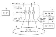
도 1은, 본 실시 형태에 따른 전압 무효 전력 제어 장치가 적용되는 전압 무효 전력 제어 시스템 전체의 구성도이다.Fig. 1 is a configuration diagram of the entire voltage reactive power control system to which the voltage reactive power control apparatus according to the present embodiment is applied.
도 1에 도시되는 바와 같이, 전압 무효 전력 제어 시스템은, 배전용 변전소(1)와, 배전용 변전소(1)에 접속된 배전 계통(2)과, 배전용 변전소(1)에 마련된 조상 설비(3)와, 배전용 변전소(1)에 접속된 축전지 시스템(4)과, 전압 무효 전력 제어 장치(5)를 구비한다.1, the voltage reactive power control system includes a
배전용 변전소(1)는 1차측 모선(11)과 2차측 모선(12)과 양쪽 모선(11, 12) 사이에 병렬로 마련된 복수의 변압기(13)를 구비한다. 1차측 모선(11)에는, 초고압 계통 등의 상위 계통이 접속되어 있다. 2차측 모선(12)에는, 배전 계통(2) 및 축전지 시스템(4)이 연계되어 있다. 변압기(13)는 탭 전환 가능한 변압기이며, 변압기(13)의 탭을 제어하는 제어 장치(도시하지 않음)와 접속되어 있고, 당해 제어 장치에 의해 변압기(13)의 탭을 제어하고, 권선비를 변경함으로써 모선(11, 12)의 전압 변동을 조정한다.The
배전 계통(2)에는, 부하와, 복수의 재생 가능 에너지 발전이 연계되어 있다. 재생 가능 에너지 발전(이하, 간단히 RE라고 칭하는 경우도 있음)은 태양광 발전, 풍력 발전 등의 자연 에너지 발전을 포함한다.In the
조상 설비(3)는 콘덴서 및 분로 리액터 등을 포함하는 전압 조정 장치이며, 여기에서는 2차측 모선(12)에 접속되어 있다. 조상 설비(3)에는, 조상 설비(3)의 제어 장치(도시하지 않음)가 마련되어 있고, 당해 제어 장치에 의해 조상 설비(3)가 조작됨으로써, 조상 설비(3)는 무효 전력을 발생시켜서 2차측 모선(12)에 주입하고, 2차측 모선(12)의 전압을 조정한다. 또한, 조상 설비(3)는 콘덴서나 리액터 외에, 로터리 콘덴서(동기 조상기) 등이어도 된다.The
변압기(13), 변압기(13)의 탭을 제어하는 제어 장치, 조상 설비(3), 및 그 제어 장치는, 종래부터 변전소에 마련되어 있는 기설의 전압 조정 장치이다.The transformer 13, the control device for controlling the taps of the transformer 13, the
축전지 시스템(4)은 2차측 모선(12)과의 사이에서 무효 전력을 주입 또는 흡수하는 것이며, 복수의 축전지와, 직류와 교류를 변환하는 교류 직류 변환기와, 당해 교류 직류 변환기의 제어 장치를 포함해 구성된다. 축전지 시스템(4)은 전압 무효 전력 제어 장치(5)와 접속되어 있고, 전압 무효 전력 제어 장치(5)의 명령을 받아서 2차측 모선(12)에 무효 전력을 주입 또는 흡수함으로써 2차측 모선(12)의 전압 변동을 억제한다.The battery system 4 is for injecting or absorbing reactive power with the secondary
전압 무효 전력 제어 장치(5)는 배전용 변전소(1)의 모선 전압 변동 중, 재생 가능 에너지 발전의 출력 변동에 수반하는 모선 전압 변동을 억제하기 위한 장치이다. 여기에서는, 2차측 모선(12)의 전압 변동을 억제하는 예를 설명한다.The voltage reactive
전압 무효 전력 제어 장치(5)는, 예를 들어 단일 컴퓨터 또는 네트워크 접속된 복수의 컴퓨터 및 표시 장치를 포함해 구성되어 있다. 전압 무효 전력 제어 장치(5)는 프로그램을 기록 매체인 HDD나 SSD 등에 기억하고 있어, RAM에 적절히 전개하고, CPU에서 처리함으로써, 후술하는 재생 가능 에너지 발전의 출력 변동에 수반하는 모선 전압 변동분의 추출 처리 등, 필요한 연산을 행한다.The voltage reactive
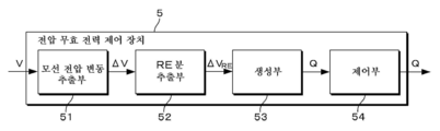
구체적으로는, 도 2에 도시되는 바와 같이, 전압 무효 전력 제어 장치(5)는 모선 전압 변동 추출부(51)와, RE분 추출부(52)와, 생성부(53)와, 제어부(54)를 구비한다.2, the voltage reactive
모선 전압 변동 추출부(51)는 계측된 2차측 모선(12)의 전압으로부터 모선 전압 변동을 추출하는 것이며, 공지된 방법에 의해 추출할 수 있다. 여기에서는, 모선 전압 변동 추출부(51)는 대역 통과 필터이다. 2차측 모선(12)의 계측 전압은, 예를 들어 2차측 모선(12)에 마련된 전압 계측기로부터 유선 또는 무선 통신 수단을 통하여 그 계측값의 입력을 접수한다. 또한, 모선 전압 변동 추출부(51)는 2차측 모선(12)에 마련된 전압 계측기로부터 다른 시각에 측정된 측정 전압을 취득하고, 측정 전압의 차분으로부터 모선 전압 변동을 구해도 되고, 당해 방법도 계측된 모선 전압으로부터 모선 전압 변동을 추출하는 것에 포함된다.The bus
RE분 추출부(52)는 모선 전압 변동 추출부(51)에 의해 얻어진 모선 전압 변동으로부터, 재생 가능 에너지 발전(RE)의 출력 변동에 의한 변동분을 추출한다. 이 RE분 추출부(52)는 모선 전압 변동 추출부(51)에 의해 얻어진 모선 전압 변동으로부터, 재생 가능 에너지 발전(RE)의 출력 변동에 의한 변동분 이외의 변동분을 제거하고, 잔존된 모선 전압 변동분을 재생 가능 에너지 발전(RE)의 출력 변동에 의한 변동분으로 한다.The
즉, RE분 추출부(52)는 하기 식 1에 나타내는 바와 같이, 모선 전압 변동 추출부(51)에 의해 얻어진 모선 전압 변동 ΔV로부터, 변압기(13)의 탭 제어에 의한 변동분 ΔVTAP, 조상 설비(3)의 조작에 의한 변동분 ΔVCNT, 배전 계통의 부하 변동에 의한 변동분 ΔVD, 상위 계통의 수급 변동에 의한 변동분 ΔVT 및 축전지 시스템의 제어에 의한 변동분ΔVB를 제거함으로써, RE분의 모선 전압 변동분 ΔVRE를 구한다.That is, as shown in the following equation (1), the
(식 1)(Equation 1)
ΔVRE=ΔV-(ΔVTAP+ΔVCNT+ΔVD+ΔVT+ΔVB)…(1)? V RE =? V- (? V TAP +? V CNT +? V D +? V T +? V B ) (One)
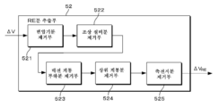
보다 상세하게는, 도 3에 도시되는 바와 같이, RE분 추출부(52)는 변압기분 제거부(521)와, 조상 설비분 제거부(522)와, 배전 계통 부하분 제거부(523)와, 상위 계통분 제거부(524)와, 축전지분 제거부(525)를 구비한다.More specifically, as shown in FIG. 3, the
변압기분 제거부(521)는 입력된 모선 전압 변동으로부터, 변압기(13)의 탭 제어에 의한 모선 전압 변동분을 제거한다. 조상 설비분 제거부(522)는 입력된 모선 전압 변동으로부터, 조상 설비(3)의 조작에 의한 모선 전압 변동분을 제거한다. 배전 계통 부하분 제거부(523)는 입력된 배전 계통(2)의 부하 변동에 의한 모선 전압 변동분을 제거한다. 상위 계통분 제거부(524)는 입력된 모선 전압 변동으로부터, 상위 계통의 수급 변동에 의한 모선 전압 변동분을 제거한다. 축전지분 제거부(525)는 입력된 모선 전압 변동으로부터, 축전지 시스템(4)의 제어에 의한 모선 전압 변동분을 제거한다.The
또한, RE분 추출부(52)에 있어서, 각 변동분의 제거 순서는 특별히 한정되지 않는다. 또한, 각 제거부(521 내지 525)에 있어서의 「입력된 모선 전압 변동」은, 모선 전압 변동 추출부(51)에 의해 얻어진 모선 전압 변동, 또는, 각 제거부(521 내지 525) 전까지의 변동분이 제거된 모선 전압 변동이다.In the RE-minute extracting
예를 들어, 도 3에 도시되는 바와 같이, RE분 추출부(52)가, 각 변동분을 제거부(521 내지 525)의 순서로 제거할 경우, 각 제거부(521 내지 525)에 입력되는 모선 전압 변동은, 다음과 같다.For example, as shown in FIG. 3, when the RE-minute extracting
(스텝 1) 변압기분 제거부(521)에 입력되는 모선 전압 변동: ΔV(Step 1) Bus line voltage variation input to the transformer distributing unit 521:? V
(스텝 2) 조상 설비분 제거부(522)에 입력되는 모선 전압 변동: ΔV-ΔVTAP (Step 2) Bus line voltage variation input to the ancillary equipment plant removal section 522: ΔV-ΔV TAP
(스텝 3) 배전 계통 부하분 제거부(523)에 입력되는 모선 전압 변동: ΔV-ΔVTAP-ΔVCNT (Step 3) Bus line voltage variation input to the distribution system load distributing unit 523: ΔV-ΔV TAP -ΔV CNT
(스텝 4) 상위 계통분 제거부(524)에 입력되는 모선 전압 변동: ΔV-ΔVTAP-ΔVCNT-ΔVD (Step 4) The bus line voltage input to the upper system distributing unit 524: ΔV-ΔV TAP -ΔV CNT -ΔV D
(스텝 5) 축전지분 제거부(525)에 입력되는 모선 전압 변동: ΔV-ΔVTAP-ΔVCNT-ΔVD-ΔVT (Step 5) The bus line voltage variation input to the
각 제거부(521 내지 525)의 각 변동분의 제거 방법에 대하여 설명한다. 변압기(13)의 탭 제어에 의한 변동분 ΔVTAP, 조상 설비(3)의 조작에 의한 변동분 ΔVCNT, 배전 계통(2)의 부하 변동에 의한 변동분 ΔVD, 상위 계통의 수급 변동에 의한 변동분 ΔVT 및 축전지 시스템(4)의 제어에 의한 변동분 ΔVB는, 모선 전압 변동ΔV를 주파수 분석했을 경우에 각각 다른 변동분에 기인하는 모선 전압 변동분과 다른 주파수 대역을 갖는 점에서, 각 제거부(521 내지 525)는, 예를 들어 각 제거부(521 내지 525)가 대상으로 하는 변동분의 고유한 주파수 대역의 모선 전압 변동분을, 입력된 모선 전압 변동으로부터 제거한다.A method of eliminating each variation of each of the eliminating
즉, 각 제거부(521 내지 525)가 대상으로 하는 변동분의 고유한 주파수 대역은, 도시되지 않은 기록 매체에 미리 기억되어 있고, 각 제거부(521 내지 525)는 당해 기록 매체로부터 자신의 고유한 주파수 대역을 취득하고, 당해 주파수 대역과 동일한 대역을 입력된 모선 전압 변동으로부터 제외하는 처리를 행한다.That is, the frequency bands unique to the
또한, 배전 계통의 부하 변동에 의한 변동분 ΔVD, 상위 계통의 수급 변동에 의한 변동분 ΔVT에 대해서는, 일반적으로 그 변동량이 작다는 점에서, 배전 계통 부하분 제거부(523)는 모선 전압 변동 ΔV 중, 소정의 역치 이하의 변동분을, ΔVD로 간주하여 제거해도 된다. 또한, 상위 계통분 제거부(524)는 모선 전압 변동 ΔV 중, 소정의 역치 이하의 변동분을, ΔVT로 간주하여 제거해도 된다.Further, variation due to the load variation of the power distribution grid ΔV D, for the variation ΔV T due to supply variations in the upper grid, generally in that the change amount is small, the power distribution grid load balancing remover 523 bus voltage change ΔV , A variation less than or equal to a predetermined threshold value may be regarded as? V D and removed. In addition, the upper grid minutes remover 524 is also of the bus voltage change ΔV, removing considered a variation of less than a predetermined threshold, to ΔV T.
또한, 배전 계통 부하 변동용 역치와, 상위 계통용 역치는, 계통의 상태, 회로 구성 등을 고려하여 적절히 설계 변경 가능하다. 이 역치들의 대소 관계는, 예를 들어 배전 계통에 있는 거리가 발전(發展)했을 경우나, 상위 계통에 발전소, 변전소가 증설된 경우 등에 변할 수 있다. 또한, 각 제거부(523, 524)는, 입력된 모선 전압 변동으로부터, 소정의 역치 이하의 변동분을 ΔVD, ΔVT로 간주하여 제거해도 된다.The power distribution system load variation threshold value and the upper system threshold value can be appropriately changed in consideration of the state of the system, the circuit configuration, and the like. The magnitude of these thresholds can change, for example, when the distance in the power distribution system develops, when power plants and substations are installed in the upper system, and so on. In addition, each of the
추가로, 축전지 시스템(4)의 제어에 의한 변동분 ΔVB는, 다음과 같이 구하여, 제거하도록 해도 된다. 즉, 도 4에 도시되는 바와 같이, RE분 추출부(52)는 축전지 시스템(4)의 제어에 의한 모선 전압 변동분 ΔVB를, 계통 상수에 기초하여 산출하는 축전지분 변동 산출부(526)를 구비하고, 축전지분 제거부(525)는 당해 축전지분 변동 산출부(526)에 의해 산출된 변동분 ΔVB를, 입력된 모선 전압 변동으로부터 제거하도록 해도 된다. 계통 상수는, 축전지 시스템(4)의 설치 장소, 모선 간의 계통 접속 상황 등에 의해 결정되는 상수이며, 예를 들어 임피던스를 들 수 있다. 축전지 시스템(4)의 제어에 의한 변동분 ΔVB는, 예를 들어 계통 상수를 K, 축전지 시스템(4)의 출력된 무효 전력을 Q라 하면, ΔVB=K×Q로부터 구할 수 있지만, 이것에 한정되지는 않는다.Further, the variation? V B under the control of the battery system 4 may be determined and removed as follows. 4, the
생성부(53)는 RE분 추출부(52)에 의해 추출된 재생 가능 에너지 발전에 의한 모선 전압 변동에 기초하여, 당해 변동을 억제하기 위한 무효 전력 명령값 Q를 생성한다. 무효 전력 명령값 Q는, 하기의 식 2에 기초하여 생성된다.The
(식 2)(Equation 2)
Q=Qbefore+KQ×ΔVRE …(2)Q = Q before + K Q x? V RE ... (2)
여기서, Qbefore는, 직전에 생성된 무효 전력 명령값이다. KQ는, 모선의 전압 변동에 대한 무효 전력 명령값의 변동을 나타내는 계통 상수이며, 축전지 시스템(4)이 결합되는 2차측 모선(12)에 모이는 송전선의 수가 증가할수록 커진다. 송전 계통의 구성에 의존하지만, KQ는 예를 들어 10 내지 15Mvar/kV이다. 또한, 식 2로부터 명확하지만, 무효 전력 명령값의 변동량 ΔQ(=Q-Qbefore)는 ΔQ=KQ×ΔVRE의 관계가 성립되고 있다. 무효 전력 명령값 Q는, 1차 지연 상수나 게인 등의 제어 상수를 가미하여 생성해도 된다.Here, Q before is the value of the reactive power command generated immediately before . K Q is a systematic constant indicating the variation of the reactive power command value with respect to the voltage variation of the bus line and becomes larger as the number of transmission lines that converge on the
제어부(54)는 생성부(53)에서 생성된 무효 전력 명령값 Q에 기초하여, 축전지 시스템(4)을 무효 전력 제어한다. 구체적으로는, 축전지 시스템(4)의 교류 직류 변환기의 제어 장치에 대하여 당해 명령값 Q를 출력하고, 축전지 시스템(4)이 출력하는 무효 전력을 당해 명령값 Q에 접근하도록 제어한다. 제어부(54)의 제어는, 예를 들어 P 제어, PI 제어, PID 제어이다.The
[1-2. 작용·효과][1-2. Action / Effect]
(1) 본 실시 형태의 전압 무효 전력 제어 장치(5)는 재생 가능 에너지 발전을 포함하는 배전 계통(2) 및 축전지 시스템(4)이 접속된 배전용 변전소(1)의 2차측 모선(12)의 전압 변동을 억제하는 전압 무효 전력 제어 장치(5)이며, 2차측 모선(12)의 전압으로부터 모선 전압 변동 ΔV를 추출하는 모선 전압 변동 추출부(51)와, 모선 전압 변동 ΔV로부터 상기 재생 가능 에너지 발전에 의한 변동분 ΔVRE를 추출하는 RE분 추출부(52)와, RE분 추출부(52)에 의해 추출된 재생 가능 에너지 발전에 의한 모선 전압 변동 ΔVRE에 기초하여, 당해 변동 ΔVRE를 억제하기 위한 무효 전력 명령값 Q를 생성하는 생성부(53)와, 무효 전력 명령값 Q에 기초하여, 축전지 시스템(4)을 무효 전력 제어하는 제어부(54)를 구비한다. RE분 추출부(52)는 모선 전압 변동 ΔV로부터 재생 가능 에너지 발전에 의한 변동분 ΔVRE 이외의 변동분을 제거함으로써 재생 가능 에너지 발전에 의한 변동분을 추출하도록 하였다.(1) The voltage reactive
이에 의해, 재생 가능 에너지 발전의 출력 계측값을 이용하지 않더라도, 간이 구성으로 기존 설비에 의한 무효 전력 제어와 협조를 도모하여 재생 가능 에너지 발전의 출력 변동에 기인하는 모선 전압 변동을 억제할 수 있다.Thereby, even if the output measurement value of the renewable energy generation is not used, it is possible to suppress the fluctuation of the bus line voltage due to the output fluctuation of the renewable energy generation by making the reactive power control and cooperation by the existing facility simple.
즉, 배전 계통에 재생 가능 에너지 발전이 복수 포함되는 경우에도, 그러한 개개의 출력 변동은 모선 전압 변동 ΔV라고 하는 형태로 집약되고, 재생 가능 에너지 발전분의 변동 이외를 제거하는 형태로 재생 가능 에너지 발전의 출력 변동에 기인하는 모선 전압 변동을 추출하고, 이것에 기초하여 축전지 시스템을 무효 전력 제어하므로, 배전 계통에 분산된 재생 가능 에너지 발전의 출력 변동을 개별로 감시하여 개별로 무효 전력 제어할 필요가 없고, 간이 구성으로 재생 가능 에너지 발전의 출력 변동에 기인하는 모선 전압 변동을 억제할 수 있다.That is, even when a plurality of renewable energy generations are included in the power distribution system, such individual output fluctuations are concentrated in the form of a bus voltage fluctuation &Dgr; V, and the renewable energy generation It is necessary to separately monitor the output fluctuation of the renewable energy generation distributed in the power distribution system and to individually control the reactive power And it is possible to suppress the fluctuation of the bus line voltage due to the output fluctuation of the renewable energy generation with the simple configuration.
또한, 모선 전압 변동 ΔV로부터, 재생 가능 에너지 발전분 ΔVRE 이외의 변동분을 제거하고 있으므로, 이것들에 포함되는 배전 계통(2)의 부하 변동에 기인하는 모선 전압 변동을 억제하려고 하는 기존 설비에 의한 무효 전력 제어와 간섭하지 않고, 협조를 도모하여 무효 전력 제어할 수 있다.In addition, since the variation other than the renewable energy generation component? V RE is removed from the bus line voltage fluctuation? V, invalidation by the existing facility for suppressing the bus line voltage fluctuation caused by the load fluctuation of the
(2) RE분 추출부(52)는 입력된 모선 전압 변동으로부터, 배전용 변전소(1)에 마련된 변압기(13)의 탭 제어에 의한 모선 전압 변동분 ΔVTAP을 제거하는 변압기분 제거부(521)와, 입력된 모선 전압 변동으로부터, 배전용 변전소(1)에 마련된 조상 설비(3)의 조작에 의한 모선 전압 변동분 ΔVCNT를 제거하는 조상 설비분 제거부(522)와, 입력된 모선 전압 변동으로부터, 배전 계통(2)의 부하 변동에 의한 모선 전압 변동분 ΔVD를 제거하는 배전 계통 부하분 제거부(523)와, 입력된 모선 전압 변동으로부터, 배전용 변전소(1)에 접속된 상위 계통의 수급 변동에 의한 모선 전압 변동분 ΔVT를 제거하는 상위 계통분 제거부(524)와, 입력된 모선 전압 변동으로부터, 축전지 시스템(4)의 제어에 의한 모선 전압 변동분 ΔVB를 제거하는 축전지분 제거부(525)를 구비하도록 하였다.(2) The
즉, 본 실시 형태에서는, 재생 가능 에너지 발전분의 변동 이외의 변동분을, 변압기(13)의 탭 제어에 의한 변동분 ΔVTAP, 조상 설비(3)의 조작에 의한 변동분 ΔVCNT, 배전 계통의 부하 변동에 의한 변동분 ΔVD, 상위 계통의 수급 변동에 의한 변동분 ΔVT 및 축전지 시스템(4)의 제어에 의한 변동분 ΔVB로 하여, 모선 전압 변동 ΔV로부터 제거하도록 하였다.In other words, in the present embodiment, the fluctuation amount other than the fluctuation of the renewable energy power generation is divided into the variation? V TAP by the tap control of the transformer 13, the variation? V CNT by the operation of the
이것에 의해, 본 실시 형태는, 재생 가능 에너지 발전의 출력 변동에 수반하는 모선 전압 변동의 억제를 대상으로 하므로, 배전용 변전소(1)에 종래부터 배치되어 있는 기설의 변압기(13)나 기설의 조상 설비(3)의 무효 전력 제어는 변경하지 않고 그대로 사용할 수 있으므로, 기설의 설비 무효 전력 제어와 간섭하지 않고, 협조를 도모하여 모선 전압 변동의 억제를 할 수 있다.Thus, the present embodiment is intended to suppress the fluctuation of the bus line voltage due to the output fluctuation of the renewable energy generation. Therefore, the conventional transformer 13 and the existing transformer 13, which are conventionally disposed in the
(3) 변압기분 제거부(521), 조상 설비분 제거부(522), 배전 계통 부하분 제거부(523), 상위 계통분 제거부(524), 또는 축전지분 제거부(525)는 각 제거부가 대상으로 하는 변동분의 고유한 주파수 대역의 모선 전압 변동을 제거하도록 하였다. 이것에 의해, 모선 전압 변동 ΔV로부터 변동분 ΔVTAP, ΔVCNT, ΔVD, ΔVT, 또는 ΔVB를 제거할 수 있고, 재생 가능 에너지 발전의 출력 변동에 수반하는 모선 전압 변동분을 추출할 수 있다.(3) The
(4) 배전 계통 부하분 제거부(523)는 모선 전압 변동 추출부(51)에 의해 추출된 모선 전압 변동 ΔV 중, 소정의 역치 이하의 변동분을, 배전 계통(2)의 부하 변동에 의한 모선 전압 변동분 ΔVD로 하여 제거하도록 하였다. 이것에 의해, 일반적으로 배전 계통(2)의 부하 변동에 의한 모선 전압 변동 ΔVD는 작다는 점에서, 소정의 역치 이하의 변동을 배전 계통(2)의 부하 변동에 의한 모선 전압 변동 ΔVD로 간주함으로써 배전 계통(2)의 부하 변동에 의한 모선 전압 변동 특유의 주파수 대역의 성분을 제거할 필요가 없어지므로, 장치 구성을 간이하게 할 수 있다.(4) The distribution system
(5) 상위 계통분 제거부(524)는 모선 전압 변동 추출부(51)에 의해 추출된 모선 전압 변동 ΔV 중, 소정의 역치 이하의 변동분을, 상위 계통의 수급 변동에 의한 모선 전압 변동분 ΔVT로 하여 제거하도록 하였다. 이것에 의해, 일반적으로 배전 계통의 부하 변동에 의한 모선 전압 변동은 작다는 점에서, 소정의 역치 이하의 변동을 상위 계통의 수급 변동에 의한 모선 전압 변동 ΔVT로 간주함으로써 상위 계통의 수급 변동에 의한 모선 전압 변동 특유의 주파수 대역의 성분을 제거할 필요가 없어지므로, 장치 구성을 간이하게 할 수 있다.5, the upper grid minutes remover 524 bus voltage variation of the line voltage fluctuations variation of less than a predetermined threshold value of ΔV extracted by the bus voltage
(6) RE분 추출부(52)는 축전지 시스템(4)의 제어에 의한 모선 전압 변동분 ΔVB를, 계통 상수에 기초하여 산출하는 축전지분 변동 산출부(526)를 구비하고, 축전지분 제거부(525)는 축전지분 변동 산출부(526)에 의해 산출된 변동분을, 입력된 모선 전압 변동으로부터 제거하도록 하였다. 이것에 의해, 축전지 시스템(4)의 제어에 의한 모선 전압 변동분 ΔVB를 추정할 수 있고, 당해 추정값을 축전지 시스템(4)의 제어에 의한 변동으로 간주하여 제거할 수 있다.(6) The
[2. 제2 실시 형태][2. Second Embodiment]
[2-1. 구성][2-1. Configuration]
제2 실시 형태는, 도 5 및 도 6을 사용하여 설명한다. 제2 실시 형태는, 제1 실시 형태의 기본 구성과 동일하다. 이하에서는, 제1 실시 형태와 상이한 점만을 설명하고, 제1 실시 형태와 동일한 부분에 대해서는 동일한 부호를 부여하여 상세한 설명은 생략한다.The second embodiment will be described with reference to Figs. 5 and 6. Fig. The second embodiment is the same as the basic configuration of the first embodiment. Only the points different from those of the first embodiment will be described below, and the same parts as those of the first embodiment are denoted by the same reference numerals, and the detailed description is omitted.
도 5는, 제2 실시 형태에 따른 전압 무효 전력 제어 장치(5)가 적용되는 전압 무효 전력 제어 시스템 전체의 구성도이다. 도 6은, 제2 실시 형태에 따른 전압 무효 전력 제어 장치(5)의 기능 블록도이다. 본 실시 형태의 전압 무효 전력 제어 장치(5)는 배전용 변전소(1) 내의 RE분의 전력 변동의 유무를 보고, RE분 추출부(52)가 추출된 ΔVRE가 적정한지 여부를 판정한다.5 is a configuration diagram of the entire voltage reactive power control system to which the voltage reactive
구체적으로는, 도 6에 도시되는 바와 같이, 본 실시 형태의 전압 무효 전력 제어 장치(5)는 전력 변동 추출부(55)와, RE분 추출부(56)와, 판정부(57)를 더 구비한다.6, the voltage reactive
전력 변동 추출부(55)는 배전용 변전소(1) 내의 전력 P로부터 전력 변동 ΔP를 추출하는 것이며, 공지된 방법에 의해 추출할 수 있다. 여기에서는, 전력 변동 추출부(55)는 대역 통과 필터이다. 당해 전력 P는, 도 5에 도시되는 바와 같이, 변압기(13)를 통과한 합계 전력이며, 각 변압기(13)의 하위에 마련된 전력계에 의해 계측된 전력을 집계한 것이다. 또한, 이 집계는, 전압 무효 전력 제어 장치(5)가 행해도 된다. 또한, 전력 변동 추출부(55)는 다른 시각의 전력 P를 취득하고, 그 차분으로부터 전력 변동 ΔP를 구해도 되고, 당해 방법도 배전용 변전소(1) 내의 전력 P로부터 전력 변동 ΔP를 추출하는 것에 포함된다.The power
RE분 추출부(56)는 전력 변동 추출부(55)에 의해 얻어진 전력 변동 ΔP로부터, 재생 가능 에너지 발전의 출력 변동에 의한 변동분 ΔPRE를 추출한다. RE분 추출부(56)는 재생 가능 에너지 발전의 출력 변동에 의한 변동분의 고유한 변동 특성을 이용하여 ΔPRE를 추출한다. 이 변동 특성으로서는, 변동의 속도, 변동 주기의 장단 등을 사용할 수 있다. 또한, RE분 추출부(56)는 재생 가능 에너지 발전의 출력 변동에 의한 변동분의 고유한 주파수 대역을 추출하도록 해도 된다.The RE-component extracting
판정부(57)는 RE분 추출부(56)로부터 ΔPRE의 입력을 받고, RE분 추출부(52)로부터 ΔVRE의 입력을 받는다. 그리고, 판정부(57)는 재생 가능 에너지 발전의 출력 변동에 의한 전력 변동분 ΔPRE의 크기 |ΔPRE|로부터, 재생 가능 에너지 발전의 출력 변동에 의한 모선 전압 변동분 ΔVRE의 적부를 판정한다.Determining
구체적으로는, 판정부(57)는 전력 변동분 ΔPRE의 크기 |ΔPRE|를 취하고, 당해 크기 |ΔPRE|가 소정의 역치 이하인지 여부를 판정하고, 소정의 역치 이하로 판정되는 경우에는, 판정부(57)는 부적당이라고 판정하고, RE분 추출부(52)로부터 입력된, 재생 가능 에너지 발전의 출력 변동에 의한 모선 전압 변동 ΔVRE를 제로로 하여 생성부(53)에 출력한다. 예를 들어, |ΔPRE|이 소정의 역치 이하이고, ΔVRE가 잔존하는(ΔVRE≠0) 경우에는, 재생 가능 에너지 발전의 출력 변동에 의한 모선 전압 변동분 이외의 변동분이 제거되지 못하였음을 의미하기 때문에, ΔVRE를 제로로 한다.In the case where it is determined whether more than a predetermined threshold value, and determines below a predetermined threshold value, | Specifically, the determining
한편, 판정부(57)는 ΔPRE의 크기가 소정의 역치 초과라고 판정했을 경우에는, 모선 전압 변동 ΔV에 ΔVRE가 포함되어 있고, 또한, ΔVRE 이외의 변동분이 완전히 제거되었다고 판단할 수 있으므로, 적정이라고 판정하고, 판정부(57)는 생성부(53)에 ΔVRE를 그대로 출력한다. 그 후의 제어는, 제1 실시 형태와 마찬가지이므로 생략한다.Meanwhile, the determining
[2-2. 작용·효과][2-2. Action / Effect]
본 실시 형태의 전압 무효 전력 제어 장치(5)는 배전용 변전소(1) 내의 전력 P로부터 전력 변동 ΔP를 추출하는 전력 변동 추출부(55)와, 전력 변동 ΔP로부터, 재생 가능 에너지 발전에 의한 변동분 ΔPRE를 추출하는 RE분 추출부(56)와, RE분 추출부(56)에 의해 추출된 변동분의 크기 |ΔPRE|로부터, RE분 추출부(52)에 의해 추출된 재생 가능 에너지 발전의 출력 변동에 의한 모선 전압 변동 ΔVRE의 적부를 판정하는 판정부(57)를 구비하고, 판정부(57)는 RE분 추출부(56)에 의해 추출된 변동분의 크기 |ΔPRE|가 소정의 역치 이하이며 부적당이라고 판정하는 경우에는, 재생 가능 에너지 발전의 출력 변동에 의한 모선 전압 변동 ΔVRE를 제로로 하여 생성부(53)에 출력하도록 하였다.The voltage reactive
이에 의해, 잘못된 ΔVRE에 기초하여 무효 전력 제어하는 것을 방지할 수 있다. 즉, RE분 추출부(52)는 모선 전압 변동 ΔV로부터, RE분 이외의 변동을 제거함으로써 RE분의 변동 ΔVRE를 구하는 방식이기 때문에, 가령 RE분 이외의 변동이 충분히 제거되지 않은 경우에도, |ΔPRE|가 소정의 역치 이하인지 여부에 의해 RE분 추출부(52)에 의해 얻어진 ΔVRE가 적정인지 여부를 확인할 수 있다. 그 때문에, RE분 추출부(52)에 의해 얻어진 ΔVRE가 부적합이라고 판정된 경우에는, RE분 추출부(52)에 의해 얻어진 ΔVRE를 제로로 하여 생성부(53)에 출력함으로써, 생성부(53) 및 제어부(54)에 의해 잘못된 ΔVRE에 기초하여 무효 전력 제어하는 일을 없앨 수 있다.Thereby, it is possible to prevent the reactive power control based on the erroneous? V RE . That is, the
[3. 기타 실시 형태][3. Other Embodiments]
본 명세서에 있어서는, 본 발명에 따른 복수의 실시 형태를 설명했지만, 이러한 실시 형태는 예로서 제시한 것으로서, 발명의 범위를 한정하는 것을 의도하지 않는다. 이상과 같은 실시 형태는, 기타 다양한 형태로 실시되는 것이 가능하고, 발명의 범위를 일탈하지 않는 범위에서, 다양한 생략이나 치환, 변경을 행할 수 있다. 이러한 실시 형태나 그 변형은, 발명의 범위나 요지에 포함되는 것과 마찬가지로, 청구범위에 기재된 발명과 그 균등의 범위에 포함되는 것이다.In the present specification, a plurality of embodiments according to the present invention have been described, but these embodiments are presented as examples, and are not intended to limit the scope of the invention. The above-described embodiments can be implemented in various other forms, and various omissions, substitutions, and alterations can be made without departing from the scope of the invention. These embodiments and their modifications fall within the scope of the invention described in claims and equivalents thereof as well as the scope and spirit of the invention.
예를 들어, 제1 실시 형태에 있어서, 배전 계통 부하분 제거부(523) 및 상위 계통분 제거부(524)는 모선 전압 변동 ΔV 중, 소정의 역치 이하의 변동을, 배전 계통 부하분, 상위 계통분 제거분의 변동으로 간주하여 제거했지만, 당해 구성을 불감대로서 파악해도 된다.For example, in the first embodiment, the distribution system
또한, 제2 실시 형태에서는, ΔVRE가 부적합이라고 판정했을 경우, 판정부(57)가 ΔVRE를 제로로 하여 생성부(53)에 출력했지만, RE분 추출부(52)가 판정부(57)가 부적합이라는 판정 결과를 받고, 추출된 ΔVRE를 제로로 하여 생성부(53)에 출력해도 된다. 또한, RE분 추출부(52)가 ΔVRE를 생성부(53)에 출력한 후, 생성부(53)는 판정부(57)의 판정 결과를 기다려서 무효 전력 명령값 Q를 생성하도록 해도 된다. 구체적으로는, 생성부(53)는 판정부(57)의 판정 결과가 부적합이라는 신호를 받은 경우에는, RE분 추출부(52)로부터 입력된 ΔVRE를 제로로 하고, 판정부(57)의 판정 결과가 적정이라는 신호를 받은 경우에는, 입력된 ΔVRE에 기초하여 무효 전력 명령값 Q를 생성한다.In the second embodiment, when it is determined that? V RE is not suitable, the
1: 배전용 변전소
11: 1차측 모선
12: 2차측 모선
13: 변압기
2: 배전 계통
3: 조상 설비
4: 축전지 시스템
5: 전압 무효 전력 제어 장치
51: 모선 전압 변동 추출부
52: RE분 추출부
521: 변압기분 제거부
522: 조상 설비분 제거부
523: 배전 계통 부하분 제거부
524: 상위 계통분 제거부
525: 축전지분 제거부
526: 축전지분 변동 산출부
53: 생성부
54: 제어부
55: 전력 변동 추출부
56: RE분 추출부
57: 판정부1: Substation for distribution
11: Primary side bus
12: Secondary bus
13: Transformer
2: Distribution system
3: Ancillary equipment
4: Battery system
5: Voltage reactive power control device
51: bus line voltage variation extracting unit
52: RE splitter
521: Transformer disintegration
522: Ancillary equipment disintegration
523: Distribution system load distribution rejection
524: Top system division rejection
525: Accumulation charge rejection
526: Capacity change calculation unit
53: Generator
54:
55: Power fluctuation extracting unit
56: RE splitter
57:
Claims (8)
상기 모선 전압으로부터 모선 전압 변동을 추출하는 제1 추출부와,
상기 모선 전압 변동으로부터 상기 재생 가능 에너지 발전에 의한 변동분을 추출하는 제2 추출부와,
상기 제2 추출부에 의해 추출된 상기 재생 가능 에너지 발전에 의한 모선 전압 변동에 기초하여, 당해 변동을 억제하기 위한 무효 전력 명령값을 생성하는 생성부와,
상기 무효 전력 명령값에 기초하여, 상기 축전지 시스템을 무효 전력 제어하는 제어부
를 구비하고,
상기 제2 추출부는,
상기 모선 전압 변동으로부터 상기 재생 가능 에너지 발전에 의한 변동분 이외의 변동분을 제거함으로써 상기 재생 가능 에너지 발전에 의한 변동분을 추출하는 전압 무효 전력 제어 장치.1. A voltage reactive power control apparatus for suppressing fluctuation of a bus voltage of a distribution substation connected to a distribution system and a battery system including renewable energy generation,
A first extraction unit for extracting a bus voltage variation from the bus voltage,
A second extraction unit for extracting a variation due to the renewable energy generation from the bus line voltage variation,
A generating unit for generating a reactive power command value for suppressing the fluctuation based on the bus line voltage fluctuation caused by the renewable energy generation extracted by the second extracting unit;
And a control unit for controlling the reactive power of the battery system based on the reactive power command value
And,
Wherein the second extracting unit comprises:
And extracts a variation due to the renewable energy generation by removing a variation component other than the variation due to the renewable energy generation from the bus line voltage variation.
상기 제2 추출부는,
입력된 모선 전압 변동으로부터, 상기 배전용 변전소에 마련된 변압기의 탭 제어에 의한 모선 전압 변동분을 제거하는 변압기분 제거부와,
입력된 모선 전압 변동으로부터, 상기 배전용 변전소에 마련된 조상 설비의 조작에 의한 모선 전압 변동분을 제거하는 조상 설비분 제거부와,
입력된 모선 전압 변동으로부터, 상기 배전 계통의 부하 변동에 의한 모선 전압 변동분을 제거하는 배전 계통 부하분 제거부와,
입력된 모선 전압 변동으로부터, 상기 배전용 변전소에 접속된 상위 계통의 수급 변동에 의한 모선 전압 변동분을 제거하는 상위 계통분 제거부와,
입력된 모선 전압 변동으로부터, 상기 축전지 시스템의 제어에 의한 모선 전압 변동분을 제거하는 축전지분 제거부
를 구비하는 전압 무효 전력 제어 장치.The method according to claim 1,
Wherein the second extracting unit comprises:
A transformer distributing section for removing a bus line voltage variation due to a tap control of a transformer provided in the distribution substation from an inputted bus line voltage variation,
An ancillary equipment disintegration unit that removes a bus voltage variation due to an operation of an ancillary equipment provided in the distribution substation from an inputted bus voltage fluctuation,
A distribution system load distribution rejection which removes a bus line voltage variation due to a load variation of the distribution system from inputted bus line voltage fluctuation,
A top grid disconnection rejection unit that removes a bus line voltage variation due to a supply / demand fluctuation of a host system connected to the distribution substation from an input bus line voltage fluctuation,
From the input bus voltage variation, a bus voltage difference caused by the control of the battery system is removed,
And the voltage reactive power control device.
상기 변압기분 제거부, 상기 조상 설비분 제거부, 상기 배전 계통 부하분 제거부, 상기 상위 계통분 제거부, 또는 상기 축전지분 제거부는, 각 제거부가 대상으로 하는 변동분의 고유한 주파수 대역의 모선 전압 변동을 제거하는 전압 무효 전력 제어 장치.3. The method of claim 2,
Wherein said power distributing means, said transformer distributing means, said ancillary equipment distributing means, said distribution system load distributing means, said upper grid distributing means, Voltage reactive power control device for eliminating variations.
상기 배전 계통 부하분 제거부는, 상기 제1 추출부에 의해 추출된 상기 모선 전압 변동 중, 소정의 역치 이하의 변동분을, 상기 배전 계통의 부하 변동에 의한 모선 전압 변동분으로 하여 제거하는 전압 무효 전력 제어 장치.The method according to claim 2 or 3,
Wherein the power distribution system load distribution eliminating unit includes a voltage reactive power control unit for removing a variation of a predetermined threshold value or less among the bus line voltage variations extracted by the first extraction unit as a bus line voltage variation due to a load variation of the power distribution system, Device.
상기 상위 계통분 제거부는, 상기 제1 추출부에 의해 추출된 상기 모선 전압 변동 중, 소정의 역치 이하의 변동분을, 상기 상위 계통의 수급 변동에 의한 모선 전압 변동분으로 하여 제거하는 전압 무효 전력 제어 장치.The method according to claim 2 or 3,
Wherein the upper system branch eliminating unit includes a voltage ineffective power controller for removing a variation of the bus line voltage extracted by the first extractor below a predetermined threshold value as a bus line voltage variation due to supply / .
상기 제2 추출부는, 상기 축전지 시스템의 제어에 의한 모선 전압 변동분을, 계통 상수에 기초하여 산출하는 축전지분 변동 산출부를 구비하고,
상기 축전지분 제거부는, 상기 축전지분 변동 산출부에 의해 산출된 변동분을, 입력된 모선 전압 변동으로부터 제거하는 전압 무효 전력 제어 장치.6. The method according to any one of claims 2 to 5,
The second extracting section includes a storage element variation calculating section that calculates a bus line voltage variation caused by the control of the storage battery system based on a systematic constant,
And the capacitor element remover removes the variation calculated by the capacitor element variation calculator from the input bus voltage fluctuation.
상기 배전용 변전소 내의 전력으로부터 전력 변동을 추출하는 제3 추출부와,
상기 전력 변동으로부터, 상기 재생 가능 에너지 발전에 의한 변동분을 추출하는 제4 추출부와,
상기 제4 추출부에 의해 추출된 변동분의 크기로부터, 상기 제2 추출부에 의해 추출된 상기 재생 가능 에너지 발전의 출력 변동에 의한 모선 전압 변동의 적부를 판정하는 판정부
를 구비하고,
상기 판정부는,
상기 제4 추출부에 의해 추출된 변동분의 크기가 소정의 역치 이하이며 부적당이라고 판정되는 경우에는, 상기 재생 가능 에너지 발전의 출력 변동에 의한 모선 전압 변동을 제로로 하여 상기 생성부에 출력하는 전압 무효 전력 제어 장치.7. The method according to any one of claims 1 to 6,
A third extracting unit for extracting a power fluctuation from the power in the distribution substation,
A fourth extracting unit for extracting a variation due to the renewable energy generation from the power fluctuation,
And a judging section for judging whether or not the busbar voltage fluctuation due to the output fluctuation of the renewable energy generation extracted by the second extracting section is valid from the magnitude of the variation extracted by the fourth extracting section,
And,
The judging unit judges,
When the magnitude of the variation extracted by the fourth extracting unit is less than or equal to a predetermined threshold value and is judged to be inadequate, the voltage deviation due to the output fluctuation of the renewable energy generation is set to zero Power control device.
컴퓨터에,
상기 모선 전압으로부터 모선 전압 변동을 추출하는 제1 추출 처리와,
상기 모선 전압 변동으로부터 상기 재생 가능 에너지 발전에 의한 변동분을 추출하는 제2 추출 처리와,
상기 제2 추출 처리에 의해 추출된 상기 재생 가능 에너지 발전에 의한 모선 전압 변동에 기초하여, 당해 변동을 억제하기 위한 무효 전력 명령값을 생성하는 생성 처리와,
상기 무효 전력 명령값에 기초하여, 상기 축전지 시스템을 무효 전력 제어하는 제어 처리
를 실행시키고,
상기 제2 추출 처리는,
입력된 모선 전압 변동으로부터, 상기 배전용 변전소에 마련된 변압기의 탭 제어에 의한 모선 전압 변동분을 제거하는 변압기분 제거 처리와,
입력된 모선 전압 변동으로부터, 상기 배전용 변전소에 마련된 조상 설비의 조작에 의한 모선 전압 변동분을 제거하는 조상 설비분 제거 처리와,
입력된 모선 전압 변동으로부터, 상기 배전 계통의 부하 변동에 의한 모선 전압 변동분을 제거하는 배전 계통 부하분 제거 처리와,
입력된 모선 전압 변동으로부터, 상기 배전용 변전소에 접속된 상위 계통의 수급 변동에 의한 모선 전압 변동분을 제거하는 상위 계통분 제거 처리와,
입력된 모선 전압 변동으로부터, 상기 축전지 시스템의 제어에 의한 모선 전압 변동분을 제거하는 축전지분 제거 처리
를 포함하는 전압 무효 전력 제어 프로그램.
A voltage reactive power control program for suppressing fluctuation of a bus voltage of a distribution substation connected to a distribution system and a battery system including renewable energy generation,
On the computer,
A first extraction process for extracting a bus voltage variation from the bus voltage,
A second extraction process for extracting a variation due to the renewable energy generation from the bus line voltage variation,
Generation processing for generating a reactive power command value for suppressing the fluctuation based on the bus line voltage fluctuation caused by the renewable energy generation extracted by the second extraction processing;
Based on the reactive power command value, control processing for controlling the reactive power of the battery system
Lt; / RTI >
The second extraction process may include:
A transformer component removing process for removing a component of a bus voltage caused by a tap control of a transformer provided in the distribution substation from an inputted bus line voltage variation;
An ancillary equipment component removing process for removing a component of a bus voltage caused by an operation of an ancillary equipment provided in the distribution substation from an inputted bus voltage fluctuation,
A distribution system load distribution elimination process for eliminating a bus line voltage variation due to a load variation of the distribution system from the input mother line voltage variation,
An upper system branch elimination processing for removing a bus line voltage variation due to a supply / demand fluctuation of an upper system connected to the distribution substation from an inputted bus line voltage fluctuation,
From the input bus voltage fluctuation to remove the bus-line voltage variation due to the control of the above-described battery system,
And a voltage reactive power control program.
Applications Claiming Priority (1)
| Application Number | Priority Date | Filing Date | Title |
|---|---|---|---|
| PCT/JP2016/056808 WO2017149762A1 (en) | 2016-03-04 | 2016-03-04 | Voltage reactive power control device and voltage reactive power control program |
Publications (2)
| Publication Number | Publication Date |
|---|---|
| KR20180098406A true KR20180098406A (en) | 2018-09-03 |
| KR102055771B1 KR102055771B1 (en) | 2019-12-13 |
Family
ID=59743626
Family Applications (1)
| Application Number | Title | Priority Date | Filing Date |
|---|---|---|---|
| KR1020187022837A Active KR102055771B1 (en) | 2016-03-04 | 2016-03-04 | Voltage reactive power control device and recording medium |
Country Status (6)
| Country | Link |
|---|---|
| US (1) | US10714937B2 (en) |
| EP (1) | EP3425760B1 (en) |
| JP (1) | JP6567758B2 (en) |
| KR (1) | KR102055771B1 (en) |
| ES (1) | ES2873227T3 (en) |
| WO (1) | WO2017149762A1 (en) |
Families Citing this family (2)
| Publication number | Priority date | Publication date | Assignee | Title |
|---|---|---|---|---|
| CN110797920B (en) * | 2019-11-08 | 2021-01-26 | 国家电网公司华中分部 | Method and device for coordinated control of multi-resource reactive power and voltage in DC near area |
| CN115241895B (en) * | 2022-09-05 | 2026-03-31 | 广东电网有限责任公司江门供电局 | Power Smoothing Method and System Based on Identification of Severe Fluctuations in Renewable Energy Resources |
Citations (4)
| Publication number | Priority date | Publication date | Assignee | Title |
|---|---|---|---|---|
| JPH08308104A (en) * | 1995-05-11 | 1996-11-22 | Hitachi Ltd | Distributed power system and control method thereof |
| KR20110016858A (en) * | 2009-06-05 | 2011-02-18 | 미츠비시 쥬고교 가부시키가이샤 | System Stabilizers, Methods and Wind Power Systems |
| JP2011211774A (en) * | 2010-03-29 | 2011-10-20 | Tokyo Electric Power Co Inc:The | Power variation estimation system |
| KR101359805B1 (en) * | 2012-09-19 | 2014-02-10 | 한국전력공사 | Apparatus and method for synthetically analyzing power system linked distributed generation |
Family Cites Families (25)
| Publication number | Priority date | Publication date | Assignee | Title |
|---|---|---|---|---|
| JP3352662B2 (en) * | 2000-02-03 | 2002-12-03 | 関西電力株式会社 | Power system stabilizing apparatus and power system stabilizing method using secondary battery system |
| JP4575272B2 (en) * | 2005-10-27 | 2010-11-04 | 株式会社日立製作所 | Distributed power system and system stabilization method |
| JP5030685B2 (en) * | 2007-06-27 | 2012-09-19 | 三菱電機株式会社 | Reactive power compensator and its control device |
| JP4763676B2 (en) * | 2007-12-27 | 2011-08-31 | 株式会社日立製作所 | Solar power system |
| JP5239767B2 (en) * | 2008-11-14 | 2013-07-17 | 株式会社明電舎 | System stabilization device |
| WO2011090096A1 (en) * | 2010-01-20 | 2011-07-28 | 三洋電機株式会社 | Charging and discharging system and charging and discharging control device |
| JP2012039821A (en) * | 2010-08-10 | 2012-02-23 | Toshiba Corp | Power fluctuation relaxing device of power generating system and power fluctuation relaxing method |
| KR101135284B1 (en) * | 2010-11-15 | 2012-04-12 | (주)인텍에프에이 | Multi-functional power conversion apparatus and method with a rechargeable battery device and reactive power control function |
| JP2012130146A (en) * | 2010-12-15 | 2012-07-05 | Kawasaki Heavy Ind Ltd | Self-supporting power supply system adjustment device and adjustment method for self-supporting power supply system |
| CN203670098U (en) * | 2011-02-16 | 2014-06-25 | 株式会社安川电机 | Power conversion device for wind power generation, wind power generation device, and wind farm |
| US10992136B2 (en) * | 2011-04-15 | 2021-04-27 | Deka Products Limited Partnership | Modular power conversion system |
| JP5786655B2 (en) * | 2011-11-02 | 2015-09-30 | ソニー株式会社 | Control system, control device, and control method |
| JP5721645B2 (en) * | 2012-02-06 | 2015-05-20 | 三菱重工業株式会社 | Wind turbine generator control device, wind turbine generator, and wind turbine generator control method |
| JP2013165593A (en) * | 2012-02-10 | 2013-08-22 | Toshiba Corp | Power generation control device, power generation control method, power generation control program and power generation control system |
| EP2940826B1 (en) * | 2012-12-27 | 2018-01-31 | Kawasaki Jukogyo Kabushiki Kaisha | Combined power generation system having power converting device |
| WO2014174667A1 (en) * | 2013-04-26 | 2014-10-30 | 富士電機株式会社 | Resonance suppression device |
| JP6020721B2 (en) * | 2013-06-05 | 2016-11-02 | 富士電機株式会社 | Power stabilization system and control device |
| JP2015061331A (en) * | 2013-09-17 | 2015-03-30 | 株式会社東芝 | Voltage fluctuation suppression device |
| CN104333026A (en) * | 2014-11-12 | 2015-02-04 | 广西大学 | Power feed-forward compensation based isolated operation direct current micro grid energy storage voltage stabilizing control method |
| JP6412822B2 (en) * | 2015-04-22 | 2018-10-24 | 株式会社日立製作所 | Power system voltage reactive power monitoring and control apparatus and method |
| JP6419977B2 (en) * | 2015-09-03 | 2018-11-14 | 株式会社東芝 | Voltage fluctuation suppressing apparatus and method |
| WO2017145316A1 (en) * | 2016-02-25 | 2017-08-31 | 株式会社 東芝 | Grid linkage facility |
| JP6725298B2 (en) * | 2016-04-04 | 2020-07-15 | 東海旅客鉄道株式会社 | Electric power conversion control device for trains |
| JP6933450B2 (en) * | 2016-06-20 | 2021-09-08 | 株式会社日立製作所 | Voltage Reactive Power Monitoring and Control Device and Method |
| EP3567690A4 (en) * | 2017-01-06 | 2020-07-22 | Kabushiki Kaisha Toshiba | REACTIVE POWER CONTROL DEVICE AND REACTIVE POWER CONTROL METHOD |
-
2016
- 2016-03-04 JP JP2018502480A patent/JP6567758B2/en active Active
- 2016-03-04 US US16/081,537 patent/US10714937B2/en active Active
- 2016-03-04 WO PCT/JP2016/056808 patent/WO2017149762A1/en not_active Ceased
- 2016-03-04 KR KR1020187022837A patent/KR102055771B1/en active Active
- 2016-03-04 ES ES16892602T patent/ES2873227T3/en active Active
- 2016-03-04 EP EP16892602.0A patent/EP3425760B1/en active Active
Patent Citations (4)
| Publication number | Priority date | Publication date | Assignee | Title |
|---|---|---|---|---|
| JPH08308104A (en) * | 1995-05-11 | 1996-11-22 | Hitachi Ltd | Distributed power system and control method thereof |
| KR20110016858A (en) * | 2009-06-05 | 2011-02-18 | 미츠비시 쥬고교 가부시키가이샤 | System Stabilizers, Methods and Wind Power Systems |
| JP2011211774A (en) * | 2010-03-29 | 2011-10-20 | Tokyo Electric Power Co Inc:The | Power variation estimation system |
| KR101359805B1 (en) * | 2012-09-19 | 2014-02-10 | 한국전력공사 | Apparatus and method for synthetically analyzing power system linked distributed generation |
Non-Patent Citations (1)
| Title |
|---|
| 우치야마 노리유키, 외 3명, 「대규모 태양광 발전 시스템의 무효 전력 제어에 의한 전압 변동 억제」, 전기 학회 논문지 B, 2010년, 130권, 3호, p.297-p.304 |
Also Published As
| Publication number | Publication date |
|---|---|
| JP6567758B2 (en) | 2019-08-28 |
| KR102055771B1 (en) | 2019-12-13 |
| JPWO2017149762A1 (en) | 2018-11-29 |
| EP3425760A4 (en) | 2019-11-20 |
| US10714937B2 (en) | 2020-07-14 |
| US20200044451A1 (en) | 2020-02-06 |
| EP3425760A1 (en) | 2019-01-09 |
| WO2017149762A1 (en) | 2017-09-08 |
| EP3425760B1 (en) | 2021-04-21 |
| ES2873227T3 (en) | 2021-11-03 |
Similar Documents
| Publication | Publication Date | Title |
|---|---|---|
| KR101132107B1 (en) | System for controlling voltage and reactive power in electric power system connected with distributed generation and method for the same | |
| US11146068B2 (en) | Method and apparatus for minimizing circulating currents in microgrids | |
| CN107431363A (en) | Storage battery management device, method and program | |
| Kim | A case study on the effect of storage systems on a distribution network enhanced by high-capacity photovoltaic systems | |
| CN113595093B (en) | Reactive voltage automatic control method and device for new energy power station and storage medium | |
| CN105098775A (en) | Microgrid Voltage Stability Control Method and System | |
| Bhatt et al. | Comprehensive assessment and mitigation of harmonic resonance in smart distribution grid with solar photovoltaic | |
| Araujo et al. | Distributed generation: Voltage stability analysis | |
| Wu et al. | Accommodating high PV penetration on the distribution system of Kinmen island | |
| KR20180098406A (en) | Voltage reactive power control device and recording medium | |
| Mohammadi et al. | DC microgrid load shedding schemes | |
| Arzani et al. | Inverter-based resource plants operation in combined transmission-distribution weak grids: A case study | |
| Vrana et al. | Battery storage and charging systems power control supporting voltage in charging mode | |
| Adrees et al. | The influence of different storage technologies on large power system frequency response | |
| CN103329386B (en) | High voltage dc power source and the power device for high-voltage electric power system | |
| Jennett et al. | Analysis of the sympathetic tripping problem for networks with high penetrations of distributed generation | |
| CN107390072B (en) | SVG Aging Test Method and Device | |
| CN105071441A (en) | Microgrid Frequency Stability Control Method and System | |
| CN106030438A (en) | System and methods of grid stabilization | |
| Bamukunde et al. | A study on mitigation techniques for reduction and elimination of solar PV output fluctuations | |
| Ramaswamy et al. | Impact of load and generation flexibility on the long term planning of YLPIC distribution network | |
| Zhixiong et al. | Coordinated control of distributed bess based on mas for voltage regulation in lv distribution network with high pv penetration | |
| Jafari et al. | The combination of load shedding and removal of capacitors in under frequency situations | |
| Fatheli et al. | Development of Load Control Algorithm for PV Microgrid. | |
| JP7838122B2 (en) | Stabilization of voltage and frequency at common connection points in industrial facilities |
Legal Events
| Date | Code | Title | Description |
|---|---|---|---|
| A201 | Request for examination | ||
| P11-X000 | Amendment of application requested |
St.27 status event code: A-2-2-P10-P11-nap-X000 |
|
| P13-X000 | Application amended |
St.27 status event code: A-2-2-P10-P13-nap-X000 |
|
| PA0105 | International application |
St.27 status event code: A-0-1-A10-A15-nap-PA0105 |
|
| PA0201 | Request for examination |
St.27 status event code: A-1-2-D10-D11-exm-PA0201 |
|
| PG1501 | Laying open of application |
St.27 status event code: A-1-1-Q10-Q12-nap-PG1501 |
|
| E902 | Notification of reason for refusal | ||
| PE0902 | Notice of grounds for rejection |
St.27 status event code: A-1-2-D10-D21-exm-PE0902 |
|
| E701 | Decision to grant or registration of patent right | ||
| PE0701 | Decision of registration |
St.27 status event code: A-1-2-D10-D22-exm-PE0701 |
|
| GRNT | Written decision to grant | ||
| PR0701 | Registration of establishment |
St.27 status event code: A-2-4-F10-F11-exm-PR0701 |
|
| PR1002 | Payment of registration fee |
St.27 status event code: A-2-2-U10-U12-oth-PR1002 Fee payment year number: 1 |
|
| PG1601 | Publication of registration |
St.27 status event code: A-4-4-Q10-Q13-nap-PG1601 |
|
| P22-X000 | Classification modified |
St.27 status event code: A-4-4-P10-P22-nap-X000 |
|
| PR1001 | Payment of annual fee |
St.27 status event code: A-4-4-U10-U11-oth-PR1001 Fee payment year number: 4 |
|
| PR1001 | Payment of annual fee |
St.27 status event code: A-4-4-U10-U11-oth-PR1001 Fee payment year number: 5 |
|
| PR1001 | Payment of annual fee |
St.27 status event code: A-4-4-U10-U11-oth-PR1001 Fee payment year number: 6 |
|
| R18 | Changes to party contact information recorded |
Free format text: ST27 STATUS EVENT CODE: A-5-5-R10-R18-OTH-X000 (AS PROVIDED BY THE NATIONAL OFFICE) |
|
| R18-X000 | Changes to party contact information recorded |
St.27 status event code: A-5-5-R10-R18-oth-X000 |
|
| P22-X000 | Classification modified |
St.27 status event code: A-4-4-P10-P22-nap-X000 |