KR20180098349A - Fixtures for the manufacture of footwear components - Google Patents
Fixtures for the manufacture of footwear components Download PDFInfo
- Publication number
- KR20180098349A KR20180098349A KR1020187021322A KR20187021322A KR20180098349A KR 20180098349 A KR20180098349 A KR 20180098349A KR 1020187021322 A KR1020187021322 A KR 1020187021322A KR 20187021322 A KR20187021322 A KR 20187021322A KR 20180098349 A KR20180098349 A KR 20180098349A
- Authority
- KR
- South Korea
- Prior art keywords
- component
- fixed portion
- compression surface
- footwear component
- adjustable
- Prior art date
- Legal status (The legal status is an assumption and is not a legal conclusion. Google has not performed a legal analysis and makes no representation as to the accuracy of the status listed.)
- Granted
Links
Images


Classifications
-
- A—HUMAN NECESSITIES
- A43—FOOTWEAR
- A43D—MACHINES, TOOLS, EQUIPMENT OR METHODS FOR MANUFACTURING OR REPAIRING FOOTWEAR
- A43D8/00—Machines for cutting, ornamenting, marking or otherwise working up shoe part blanks
- A43D8/32—Working on edges or margins
-
- A—HUMAN NECESSITIES
- A43—FOOTWEAR
- A43D—MACHINES, TOOLS, EQUIPMENT OR METHODS FOR MANUFACTURING OR REPAIRING FOOTWEAR
- A43D95/00—Shoe-finishing machines
- A43D95/14—Shoe-finishing machines incorporating marking, printing, or embossing apparatus
-
- A—HUMAN NECESSITIES
- A43—FOOTWEAR
- A43D—MACHINES, TOOLS, EQUIPMENT OR METHODS FOR MANUFACTURING OR REPAIRING FOOTWEAR
- A43D5/00—Hand appliances or hand tools for making or repairing shoes, other than those covered by groups A43D15/00, A43D19/00, A43D95/00, A43D100/00, A43D117/00
- A43D5/02—Stands for making footwear
-
- A—HUMAN NECESSITIES
- A43—FOOTWEAR
- A43D—MACHINES, TOOLS, EQUIPMENT OR METHODS FOR MANUFACTURING OR REPAIRING FOOTWEAR
- A43D8/00—Machines for cutting, ornamenting, marking or otherwise working up shoe part blanks
- A43D8/02—Cutting-out
-
- A—HUMAN NECESSITIES
- A43—FOOTWEAR
- A43D—MACHINES, TOOLS, EQUIPMENT OR METHODS FOR MANUFACTURING OR REPAIRING FOOTWEAR
- A43D8/00—Machines for cutting, ornamenting, marking or otherwise working up shoe part blanks
- A43D8/32—Working on edges or margins
- A43D8/36—Working on edges or margins by trimming the margins of sole blanks
-
- A—HUMAN NECESSITIES
- A43—FOOTWEAR
- A43D—MACHINES, TOOLS, EQUIPMENT OR METHODS FOR MANUFACTURING OR REPAIRING FOOTWEAR
- A43D95/00—Shoe-finishing machines
- A43D95/24—Machines for buffing soles
Landscapes
- Footwear And Its Accessory, Manufacturing Method And Apparatuses (AREA)
Abstract
신발류 구성요소 제조용 고정기구가, 표면들을 가리지 않는 가운데 구성요소의 하나 이상의 표면의 처리를 허용하는 방식으로, 신발 밑창과 같은 구성요소를 고정한다. 고정기구는, 제1 압축 표면을 갖는 고정된 부분 및 제2 압축 표면을 갖는 조절 가능 부분을 구비한다. 조절 가능 부분은, 고정된 부분에 관하여, 처리하기 위해 고정기구에 구성요소를 고정하기 위해 압축 표면들 사이에 구성요소의 하나 이상의 돌출부를 압축하도록, 이동한다.A fixture for the manufacture of footwear components fixes components such as shoe soles, in a manner that allows for the treatment of one or more surfaces of the components, without disturbing the surfaces. The fastening mechanism includes a fixed portion having a first compression surface and an adjustable portion having a second compression surface. The adjustable portion moves relative to the fixed portion to compress one or more protrusions of the component between the compression surfaces to secure the component to the fixture for processing.
Description
양태들은, 고정기구 및 신발류 구성요소들의 제조 시의 고정기구의 용도를 제공한다.Embodiments provide for the use of a fixture in the manufacture of fixture and footwear components.
신발, 샌들, 부츠 및 이와 유사한 것과 같은 신발류는, 하부 유닛을 포함할 수 있을 것이다. 하부 유닛은, 사용자에 의해 착용될 때 지표면과 접촉하도록 의도될 수 있는, 밑창 구조물일 수 있을 것이다. 지면-접촉 표면 및 측벽 표면과 같은, 하부 유닛의 여러 표면들은, 그에 대해 실행되는 처리들을 가질 수 있을 것이다. 처리들은, 도색, 절단, 사이핑(siping), 연마(buffing), 스캐닝, 펀칭, 엠보싱 및/또는 이와 유사한 것을 포함할 수 있을 것이다.Footwear such as shoes, sandals, boots and the like may include a lower unit. The lower unit may be a sole structure, which may be intended to contact the ground surface when worn by a user. The various surfaces of the lower unit, such as the ground-contacting surface and the sidewall surface, may have processes performed thereon. The treatments may include painting, cutting, siping, buffing, scanning, punching, embossing and / or the like.
본 발명의 양태들은, 신발류 구성요소 제조용 고정기구 및 그의 용도를 제공한다. 고정기구는, 제1 압축 표면을 갖는 고정된 부분 및 제2 압축 표면을 갖는 조절 가능 부분을 포함한다. 조절 가능 부분은, 적어도 유지 위치와 수용 위치 사이에서, 고정된 부분에 이동 가능하게 결합된다. 제1 압축 표면은, 수용 위치에 놓일 때보다 유지 위치에서, 제2 압축 표면에 대해 더 가깝게 인접한다. 고정기구는, 고정된 부분과 조절 가능 부분 사이에서 연장되는, 조절 메커니즘을 더 포함한다. 조절 메커니즘은, 부분적으로, 고정된 부분과 조절 가능 부분 사이의 이동 가능한 결합을 제공한다.Aspects of the present invention provide a fixture for the manufacture of footwear components and uses thereof. The fixture includes a fixed portion having a first compression surface and an adjustable portion having a second compression surface. The adjustable portion is movably coupled to the fixed portion, at least between the holding position and the receiving position. The first compression surface is closer to the second compression surface in the retaining position than when it is in the receiving position. The fixture mechanism further includes an adjustment mechanism extending between the fixed portion and the adjustable portion. The adjustment mechanism provides, in part, a movable connection between the fixed portion and the adjustable portion.
이러한 개요는, 이하에 완전히 상세하게 제공되는 방법들 및 시스템들의 범위를 밝히기 위해 그리고 제한하지 않도록 하기 위해 제공된다.This summary is provided to provide, and not to limit, the scope of the methods and systems described in full below.
본 발명은, 첨부 도면들을 참조하여 여기에서 상세하게 설명된다:
도 1은, 본 발명의 양태들에 따른, 신발류 구성요소 제조용 고정기구를 도시하고;
도 2는, 본 발명의 양태들에 따른, 수용 위치에서의 도 1의 고정기구를 도시하며;
도 3은, 본 발명의 양태들에 따른, 예시적인 신발류 구성요소를 도시하고;
도 4는, 본 발명의 양태들에 따른, 수용 위치에서의 고정된 부분 및 조절 가능 부분을 구비하는 도 1의 고정기구를 도시하며;
도 5는, 본 발명의 양태들에 따른, 도 1의 고정기구의 구성요소-지향 표면과 소통 상태에 놓이는 도 3의 구성요소의 발-지향 표면을 도시하고;
도 6은, 본 발명의 양태들에 따른, 도 3의 신발류 구성요소의 돌출부들이 고정된 부분과 조절 가능 부분 사이에서 압축되도록 하는, 유지 위치에서의 도 1의 고정기구를 도시하며;
도 7은, 본 발명의 양태들에 따른, 수용 부재들, 돌출부들, 및/또는 유지 부재들의 조정 구성을 구비하는, 고정기구 및 구성요소의 평면도를 도시하고;
도 8은, 본 발명의 양태들에 따른, 수용 부재들, 돌출부들, 및/또는 유지 부재들의 조정 구성을 구비하는, 대안적인 고정기구 및 구성요소의 평면도를 도시하며;
도 9는, 본 발명의 양태들에 따른, 예시적인 고정기구의 평면도를 도시하며; 그리고
도 10은, 본 발명의 양태들에 따른, 고정기구 상에서 신발류 구성요소를 처리하는 방법을 나타내는 흐름도를 도시한다.The present invention is described in detail herein with reference to the accompanying drawings, in which:
BRIEF DESCRIPTION OF THE DRAWINGS Figure 1 shows a securing mechanism for the manufacture of a footwear component, in accordance with aspects of the present invention;
Figure 2 shows the locking mechanism of Figure 1 in the receiving position, in accordance with aspects of the present invention;
Figure 3 illustrates an exemplary footwear component, in accordance with aspects of the present invention;
Figure 4 illustrates the locking mechanism of Figure 1 with a fixed portion and an adjustable portion at a receiving position, in accordance with aspects of the present invention;
Figure 5 shows the foot-oriented surface of the component of Figure 3 in communication with the component-oriented surface of the fixture of Figure 1, in accordance with aspects of the present invention;
Fig. 6 shows the locking mechanism of Fig. 1 in the retention position, allowing the protrusions of the footwear component of Fig. 3 to compress between the fixed portion and the adjustable portion, according to aspects of the present invention;
Figure 7 shows a top view of a securing mechanism and components comprising an adjusting arrangement of receiving members, protrusions, and / or retaining members, according to aspects of the present invention;
8 shows a top view of an alternative locking mechanism and component, with an adjustment arrangement of receiving members, protrusions, and / or retaining members, according to aspects of the present invention;
Figure 9 shows a top view of an exemplary fixture, in accordance with aspects of the present invention; And
Figure 10 shows a flow diagram illustrating a method of processing footwear components on a fixture, in accordance with aspects of the present invention.
양태들은, 고정기구에 대해 고정된 위치에, 중창, 바닥창, 또는 이들의 조합을 포함할 수 있는 밑창 구조물과 같은, 신발류 하부 유닛을 유지하도록 구성되는 고정기구를 제공한다. 하부 유닛을 고정기구에 고정함에 의해, 고정기구는, 하나 이상의 프로세스가 하부 유닛에 실행되는 것을 허용하기 위해 필요할 때, 이동 또는 위치 설정될 수 있다. 구체적으로, 고정기구는, 실행될 하나 이상의 제조 프로세스를 위해 지면-접촉 표면 및/또는 측벽 표면이 노출되는 것을 허용하도록, 하부 유닛의 발-지향 표면에 인접하게 배치될 수 있다. 예를 들어, 레이저 사이핑 기계가, 트레드 유사 구조를 위한 사이프들(sipes)을 형성하기 위해 하부 유닛의 지면-접촉 표면에 레이저 에너지를 가할 수 있을 것이다. 고정기구가, 하부 유닛의 발-지향 표면 상에 배치되기 때문에, 레이저 사이핑 프로세스는, 고정기구에 대해 하부 유닛을 재배치하지 않고, 하부 유닛의 지면 접촉 표면 상에 실행될 수 있을 것이다.Embodiments provide a locking mechanism configured to hold a footwear lower unit, such as a sole structure, which may include a midsole, a floor pane, or a combination thereof, in a fixed position relative to the securing mechanism. By securing the lower unit to the securing mechanism, the securing mechanism can be moved or positioned as needed to allow one or more processes to be performed on the lower unit. Specifically, the locking mechanism may be disposed adjacent the foot-oriented surface of the lower unit to allow the ground-contacting surface and / or side wall surface to be exposed for one or more manufacturing processes to be performed. For example, a laser siphoning machine may apply laser energy to the ground-contacting surface of the lower unit to form sipes for a tread-like structure. Since the locking mechanism is disposed on the foot-oriented surface of the lower unit, the laser siping process will be able to be performed on the ground contact surface of the lower unit, without relocating the lower unit relative to the locking mechanism.
그에 따라, 예시적인 양태에서, 고정기구는, X-Y 평면(예를 들어, 발가락쪽에서 뒤꿈치쪽 및 안쪽에서 바깥쪽 평면) 및 수직 윤곽(X-Y 평면으로부터 연장되는 곡률 및 수직 형상) 중의 하나 이상에 관해, 구성요소-지향 표면에서 대략 신발-형 윤곽을 갖는다. 이러한 형상 모사(mimicking)는, 프로세스들이 고정기구에 의해 고정됨에 따라 하부 유닛 상에 실행될 때, 일관적인 결과를 보장하기 위한, 지지 및 안정성이, 고정기구에 의해 제공되도록, 고정기구와 하부 유닛 사이의 충분한 접촉을 허용한다. 그에 따라, 고정기구가, 이하에서 도 9와 함께 더욱 상세하게 논의될 것으로서, 고정기구에 의해 유지될 하부 유닛의 평면 모양을 모사하는, 발가락 영역, 중족 영역, 및 뒤꿈치 영역을 구비하는 것이, 예상된다. 발가락 영역은, 중족 영역 및 뒤꿈치 영역보다 더 큰 횡단 폭을 갖는다. 뒤꿈치 영역은, 항상 그런 것은 아니지만, 예시적인 양태에서, 중족 영역보다 더 큰 횡단 폭을 갖는다. 대안적인 양태에서, 고정기구가, 하부 유닛의 평면 윤곽 또는 수직 윤곽을 모사하지 않는 대신, 다른 위치들에서 하부 유닛과 접촉하지 않고, 하부 유닛에 대해 선택된 영역에서 지지를 제공하도록 구성되는 것이, 예상된다. 예를 들어, 프로세스가 단지 하부 유닛의 발가락 영역에서만 실행될 경우, 고정기구는, 발가락 영역에서 하부 유닛의 대략적 형상을 모사할 수 있으며, 그리고 하부 유닛의 뒤꿈치 영역에서 임의의 구성을 취하거나 또는 심지어 생략될 수 있을 것이다. 그에 따라, 고정기구가, 하부 유닛 상에 실행되는 프로세스 도중에 지지 및 안정성을 제공하기 위한 방식으로, 하부 유닛과 어울리는 형상을 가질 수 있다는 것이, 예상된다.Thus, in an exemplary embodiment, the fixture may be configured such that with respect to one or more of the XY plane (e.g., from the toe side to the heel side and from the inside to the outside plane) and the vertical contour (curvature and vertical shape extending from the XY plane) It has a shoe-shaped contour at the component-oriented surface. This shape mimicking is achieved by providing a support and stability for ensuring consistent results when the processes are carried out on the lower unit as they are fixed by the fixture, Lt; / RTI > Accordingly, it will be appreciated that having a toe region, midsole region, and heel region, which simulates the planar shape of the lower unit to be held by the anchoring mechanism, as will be discussed in more detail below with FIG. 9, do. The toe region has a greater transverse width than the midsole region and the heel region. The heel region, although not always, has, in an exemplary embodiment, a greater transverse width than the midsole region. It is contemplated that in an alternative embodiment the fixture may be configured to provide support in a selected area relative to the lower unit without contacting the lower unit at other locations instead of not simulating a planar contour or vertical contour of the lower unit, do. For example, if the process is performed only in the toe area of the lower unit, the anchoring mechanism can simulate the approximate shape of the lower unit in the toe area and take any configuration in the heel area of the lower unit, . Accordingly, it is envisioned that the fixture can have a shape that matches the lower unit, in a manner to provide support and stability during the process performed on the lower unit.
고정기구는, 예시적인 양태에서, 고정기구에 대해 하부 유닛을 유지하기 위해, 하부 유닛으로부터 돌출하는 하나 이상의 돌출부를 압축한다. 예를 들어, 하부 유닛이, 발-지향 표면으로부터 연장되는 하나 이상의 일체형으로 형성된 돌출부를 구비하는 것이, 예상된다. 돌출부(들)는 일반적으로, 일체형으로 형성되지 않을 수 있으며 그리고, 이들이 부가적인 재료들을 소모함에 따라 그리고 착용 시 하부 유닛에 대한 사용자의 인식에 영향을 미치지 않도록 전통적으로 돌출부 없이 유지되는 표면으로부터 외향으로 연장됨에 따라, 발-지향 표면으로부터 연장될 수 있을 것이다. 하부 유닛으로부터 연장되는 하나 이상의 돌출부는, 예시적인 양태에서, 고정기구의 고정된 부분과 조절 가능 부분 사이에서 압축된다. 예를 들어, 스크류-형 요소와 같은, 조절 메커니즘이, 고정기구의 조절 가능 부분과 고정된 부분 사이에 하나 이상의 돌출부를 파지하고 유지하기 위해, 조절 가능 부분을 고정된 부분에 대해 이동 가능하게 배치할 수 있을 것이다.The locking mechanism, in the exemplary embodiment, compresses one or more protrusions that protrude from the lower unit to hold the lower unit relative to the locking mechanism. For example, it is envisioned that the lower unit has one or more integrally formed protrusions extending from the foot-oriented surface. The protrusions (s) may, in general, not be integrally formed and may be formed outwardly from a surface that is conventionally retained without protrusions so that they do not affect the user's perception of the lower unit as it wears additional materials and, As it extends, it may extend from the foot-oriented surface. The at least one projection extending from the lower unit, in the exemplary embodiment, is compressed between the fixed portion and the adjustable portion of the fixture. For example, an adjustment mechanism, such as a screw-type element, may be arranged to movably place the adjustable portion relative to the fixed portion to grasp and hold one or more protrusions between the adjustable portion and the fixed portion of the fixture mechanism You can do it.
본 발명의 양태들은, 신발류 구성요소 제조용 고정기구 및 그의 용도를 제공한다. 고정기구는, 제1 압축 표면을 갖는 고정된 부분 및 제2 압축 표면을 갖는 조절 가능 부분을 포함한다. 조절 가능 부분은, 적어도 유지 위치와 수용 위치 사이에서, 고정된 부분에 이동 가능하게 결합된다. 제1 압축 표면은, 수용 위치에 놓일 때보다 유지 위치에서, 제2 압축 표면에 대해 더 가깝게 인접한다. 고정기구는, 고정된 부분과 조절 가능 부분 사이에서 연장되는, 조절 메커니즘을 더 포함한다. 조절 메커니즘은, 부분적으로, 고정된 부분과 조절 가능 부분 사이의 이동 가능한 결합을 제공한다.Aspects of the present invention provide a fixture for the manufacture of footwear components and uses thereof. The fixture includes a fixed portion having a first compression surface and an adjustable portion having a second compression surface. The adjustable portion is movably coupled to the fixed portion, at least between the holding position and the receiving position. The first compression surface is closer to the second compression surface in the retaining position than when it is in the receiving position. The fixture mechanism further includes an adjustment mechanism extending between the fixed portion and the adjustable portion. The adjustment mechanism provides, in part, a movable connection between the fixed portion and the adjustable portion.
부가적인 양태들이, 고정기구 상에서, 하부 유닛과 같은 신발류 구성요소를 처리하는 방법을 예상한다. 방법은, 고정기구의 고정된 부분의 제1 압축 표면과 고정기구의 조절 가능 부분의 제2 압축 표면 사이에 신발류 구성요소의 제1 돌출부를 삽입하는 단계를 포함한다. 제1 돌출부는, 신발류 구성요소의 발-지향 표면으로부터 연장된다. 방법은 또한, 제1 압축 표면 및 제2 압축 표면이, 고정기구가 고정기구에 대해 신발류 구성요소를 유지하는 것을 허용하기 위해, 제1 돌출부와 접촉하도록, 조절 가능 부분을 고정된 부분을 향해 슬라이딩 이동시키는 단계를 포함한다. 신발류 구성요소를 유지시킨 이후에, 고정기구에 의해 유지될 때 신발류 구성요소를 처리하는 단계; 및 신발류 구성요소를 처리하는 단계에 이어서, 제1 압축 표면 및 제2 압축 표면이 제1 돌출부와 맞물림 해제되도록 조절 가능 부분을 고정된 부분으로부터 멀어지게 슬라이딩 이동시키는 단계가, 실행된다. 방법은 또한, 고정기구로부터 신발류 구성요소를 맞물림 해제시키기 위해, 제1 돌출부를 제1 압축 표면과 제2 압축 표면 사이로부터 제거하는 단계를 포함할 수 있을 것이다.Additional aspects contemplate methods of processing footwear components, such as lower units, on a fixture. The method includes inserting a first protrusion of the footwear component between a first compression surface of a fixed portion of the fixation device and a second compression surface of the adjustable portion of the fixation device. The first projection extends from the foot-oriented surface of the footwear component. The method also includes the steps of moving the adjustable portion toward the fixed portion such that the first compression surface and the second compression surface contact the first projection to allow the retaining mechanism to retain the footwear component relative to the retaining mechanism, . Treating the footwear component when retained by the fixture after retaining the footwear component; And following the step of processing the footwear component, sliding the adjustable portion away from the fixed portion such that the first compression surface and the second compression surface are disengaged from the first projection is performed. The method may also include removing the first projection from between the first compression surface and the second compression surface to disengage the footwear component from the fixture.
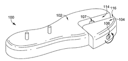
도 1은, 본 발명의 양태들에 따른, 신발류 구성요소 제조용 고정기구(100)를 도시한다. 고정기구(100)는, 고정된 부분(102), 조절 가능 부분(104), 조절 메커니즘(106), 제1 구성요소-접촉 표면(109), 제2 구성요소-접촉 표면(108), 제1 유지 부재(110), 및 제2 유지 부재(112)를 포함한다. 여러 요소들의 특수한 배열, 상대적 위치, 개수, 및 형상이 도시되지만, 요소들의 임의의 배열, 상대적 위치, 개수, 및/또는 형상이 구현될 수 있다는 것이, 예상된다. 예를 들어, 유지 부재(들)는, 임의의 크기, 형상, 위치, 배열, 및 개수의 것일 수 있을 것이다. 유사하게, 고정기구는, 전체로서, 예를 들어, 도 7 내지 도 9에 도시될 것으로서, 임의의 형상, 크기, 및/또는 구성의 것일 수 있을 것이다. 유사하게, 조절 가능 부분은, 본 명세서에 제공되는 양태들을 달성하기 위한, 임의의 크기, 형상, 및 고정된 부분에 대한 상대적 위치의 것일 수 있을 것이다. FIG. 1 illustrates a
고정기구(100)는, 금속 재료(예를 들어, 알루미늄, 강철), 중합체-계열 재료(고밀도 폴리에틸렌, 저밀도 폴리에틸렌, 폴리프로필렌, 폴리스티렌, 폴리비닐클로라이드), 및 이와 유사한 것과 같은, 임의의 재료로 형성될 수 있을 것이다. 고정기구(100)의 하나 이상의 부분이, 상이한 재료들로 형성될 수 있을 것이다. 예를 들어, 유지 부재들(110, 112)은, 고정된 부분(102) 및/또는 조절 가능 부분(104)과 상이한 재료로 형성될 수 있을 것이다.The
고정기구(100)는, 도시된 바와 같이, 하부 유닛 평면의 윤곽을 모사하는 대략적 평면 윤곽을 구비한다. 예를 들어, 발가락 영역이, 중족 영역 및 뒤꿈치 영역보다 더 넓다. 뒤꿈치 영역은, 예시적 양태에서, 중족 영역보다 더 넓다. 고정기구(100)의 종단 길이(예를 들어, 발가락측 단부에서 뒤꿈치측 단부까지)가, 유지될 하부 유닛의 크기에 의존하여 변할 수 있을 것이다. 예를 들어, 종단 방향으로의 신발 크기가, 10 센티미터("cm") 내지 40 cm(또는 이보다 더 큰)의 범위 내에 놓일 수 있을 것이다. 그에 따라, 고정기구(100)의 종단 길이가, 일부 양태에서, 10 cm 내지 40 cm 사이와 같은, 유사한 범위를 가질 수 있다는 것이, 예상된다. 그러나, 대안적인 양태에서, 길이는, 10 cm 미만 또는 40 cm 초과일 수 있다는 것이, 예상된다. 고정기구(100)의 폭이 또한, 그 위에 유지될 하부 유닛의 폭과 조화될 수 있을 것이다. 본 명세서에서 사용되는 바와 같은 폭은, 고정기구(100)의 횡단 치수(예를 들어, 안쪽에서 바깥쪽)이다. 고정기구는, 예시적인 양태에서, 8 cm 내지 14 cm의 범위의, 가장 넓은 부분(예를 들어, 볼 폭으로 언급될 수 있는, 발가락 영역의 뒤꿈치 지향 단부)에서 폭을 가질 수 있다는 것이, 예상된다. 그러나, 고정기구의 폭이, 가장 넓은 횡단 위치에서 8 cm 미만 또는 14 cm 초과일 수 있다는 것이, 예상된다. 그에 따라, 중족 영역의, 그의 가장 좁은 위치에서의, 폭이, 뒤꿈치 영역 또는 발가락 영역보다, 그들의 가장 넓은 폭에서, 적을 수 있다는 것이, 예상된다. 본 명세서에서 사용되는 바와 같이, 발가락 영역의 폭은, 접촉 관계(예를 들어, 접촉 상태의 압축 표면들)의 고정된 부분과 조절 가능 부분을 예상한다.The
더불어, 고정기구는, 발-지향 표면과 고정기구를 어울리도록 하기 위해 함께 대응하는, 수직 방향으로의 윤곽을 갖는다는 것이, 예상된다. 이러한 윤곽 배열 미러링은, 하나 이상의 프로세스가 하부 유닛 상에 실행될 때, 고정기구가 하부 유닛에 안정성을 제공하는 것을 허용한다. 이러한 안정성 및 지지는, 하부 유닛이 대응하는 윤곽들 및 형상을 구비하는 고정기구에 의해 확고하게 유지됨에 따라, 일관적인 처리 결과를 허용한다.In addition, it is envisioned that the fastening mechanism has a corresponding, vertical contour, so as to match the foot-oriented surface and the fastening mechanism. This contoured mirroring allows the locking mechanism to provide stability to the lower unit when one or more processes are executed on the lower unit. This stability and support allows consistent treatment results as the lower unit is firmly held by a locking mechanism with corresponding contours and shapes.
고정된 부분(102)은, 고정기구(100)의 위치를 조작 또는 유지하기 위해 하나 이상의 장치에 고정될 수 있을 것이다. 예를 들어, 고정된 부분(102)이, 그 위에 유지되는 하부 유닛을 갖는 고정기구(100)를, 하부 유닛이 장치들/기계들에 의해 처리되는 것을 허용하도록 제조 장치들/기계들에 대해, 이동시키기 위한 복수-축 이동 메커니즘에 고정된다는 것이, 예상된다. 추가로, 유지 부재들(110, 112) 중의 하나 이상이, 신발류 구성요소가 알려진 상대적 개소에서 고정된 부분(102)에 유지되도록, 고정된 부분(102) 상에 배치되는 것이, 예상된다. 그리고 결과적으로, 구성요소와, 구성요소를 유지하는 고정기구에 결합되는 이동 장치 사이의 알려진 상대적 개소가, 조절 메커니즘 또는 조절 가능 부분의 위치와 무관하다. 고정된 부분(102)은 그에 따라, 신발류 구성요소 상의 개소가 실행될 하나 이상의 프로세스를 위해 그로부터 병진이동될 수 있는 것인, 알려진 논리적 위치로서 역할을 할 수 있을 것이다.The anchored
예시적인 양태에서, 고정된 부분(102)은, 50%를 초과하는 고정기구(100)의 구성요소-접촉 표면을 형성한다. 다른 예시적인 양태에서, 고정된 부분(102)은, 66%를 초과하는 고정기구(100)의 구성요소-접촉 표면을 형성한다. 또 다른 예시적인 양태에서, 고정된 부분(102)은, 75%를 초과하는 고정기구(100)의 구성요소-접촉 표면을 형성한다. In an exemplary embodiment, the fixed
대안적인 관점에서, 고정된 부분(102)은, 예를 들어 도 1에 도시된 바와 같이, 뒤꿈치 영역 및 중족 영역을 형성한다. 이러한 예에 추가하여, 고정된 부분(102)은 또한, 예시적인 양태에서, 구성요소-접촉 표면에서, 발가락 영역의 적어도 일부분을 형성한다. 그러나, 고정된 부분(102)은, (예를 들어, 이하의 도 8에 도시되는 바와 같이) 발가락측 단부에서와 같은, 하나 이상의 개소에서, 구성요소-접촉 표면을 형성하지 않을 수 있다는 것이, 예상된다. In an alternative aspect, the fixed
조절 가능 부분(104)은, 고정된 부분(102)에 대해 이동한다. 이러한 상대적 이동은, 조절 가능 부분(104)과 고정된 부분(102) 사이에서 하나 이상의 돌출부의 압축을 허용한다. 조절 가능 부분(104)은, 상이한 양태에서, 임의의 개소에 놓일 수 있을 것이다. 그러나, 고정기구 상에 유지될 신발류 구성요소가, 조절 가능 부분과 고정된 부분이 수렴하는 곳의 상대적 위치에 기초하여 적절하게 배치되는 돌출부를 갖도록 구성된다는 것이, 예상된다. 도 1에 도시된 바와 같이, 조절 가능 부분은, 발가락 영역의 바깥쪽 부분을 형성하지만; 조절 가능 부분은, 임의의 부분(예를 들어, 발가락 영역의 안쪽 부분, 고정기구의 종단 길이의 바깥쪽 부분, 고정기구의 종단 길이의 안쪽 부분, 발가락측 단부 부분, 뒤꿈치측 단부 부분, 뒤꿈치 영역의 안쪽 부분, 뒤꿈치 영역의 바깥쪽 부분, 중족 영역의 안쪽 부분, 및/또는 중족 영역의 바깥쪽 부분)을 형성할 수 있을 것이다.The
조합으로, 고정된 부분(102)과 조절 가능 부분이, 발-지향 표면으로부터 신발 밑창을 지지하고 유지하는데 적당하다는 것이, 예상된다. 그에 따라, 조합은, 예시적인 양태에서, 밑창-형 형상을 갖는 것으로 예상된다.In combination, it is envisioned that the fixed
조절 메커니즘(106)은, 압축력이 고정된 부분(102)과 조절 가능 부분(104) 사이에서 하부 유닛의 돌출부 상에 가해질 때, 압축이 고정기구(100)에 대해 하부 유닛을 고정하기 위해 유지되도록, 조절 가능 부분(104)을 (예를 들어, 이하에 도 6에 도시되는 바와 같은) 유지 위치에 배치하고 유지한다. 이동 메커니즘의 도시된 구성이, 조절 가능 부분(104)을 통해 고정된 부분(102) 내로 연장되는, 나사 형성 요소이다. 조절 메커니즘(106)의 회전 운동이, 일 예에서, 조절 가능 부분(104)의 고정된 부분(102)에 대한 슬라이딩 운동으로 변환된다는 것이, 예상된다. 조절 가능 부분(104)은, 예시적인 실시예에서, 조절 메커니즘(106)이 회전됨에 따라, 조절 메커니즘(106)의 길이를 따라 이동한다는 것이, 예상된다. 대안적으로, 조절 가능 부분(104)은, 예시적인 양태에서, 조절 메커니즘(106)이 고정된 부분(102)에 대해 슬라이딩하는 동안에, 조절 메커니즘(106)에 대해 고정된 위치에 유지된다는 것이, 예상된다. 달리 진술하면, 조절 메커니즘(106)의 회전이, 조절 메커니즘(106)의 길이를 따라 조절 가능 부분(104)을 슬라이딩시킬 수 있으며, 또는 조절 메커니즘(106)이, 조절 메커니즘(106)이 고정된 부분(102)의 안팎으로 진입 또는 진출됨에 따라, 고정된 부분(102)에 대해 슬라이딩할 수 있을 것이다.The
대안적인 구성들이, 이동 메커니즘에 대해 예상된다. 예를 들어, 늑골-형 구조(ribbed-like structure) 및, 고정된 부분(102)과 조절 가능 부분(104) 사이의 압축을 유지하기 위해 늑골-형 구조와 맞물리는 래치-형 구조가, 예상된다. 또한 대안으로서, 고정된 부분(102)과 조절 가능 부분(104) 사이의 압축력을 유지하기 위해, 하나 이상의 막대 또는 스트립 요소와 맞물리는, 마찰 잠금이, 예상된다. 또한 추가로, 공압 구동 및/또는 유압 구동 메커니즘이, 사용될 수 있을 것이다. 예를 들어, 피스톤을 포함하는 실린더가, 부분들의 서로에 대한 슬라이딩 이동을 허용하기 위해, 고정된 부분(102) 및 조절 가능 부분(104)에 고정될 수 있을 것이다. 이동 메커니즘은, 하나 이상의 컴퓨터 장치에 의해 자동화되고 제어될 수 있을 것이다.Alternative configurations are expected for the transport mechanism. For example, a latch-like structure that engages a ribbed-like structure and a rib-like structure to maintain compression between the fixed
조절 메커니즘은, 도 1에 도시된 바와 같이, 고정된 부분(102) 및 조절 가능 부분(104) 양자 모두와 이동 가능하게 결합된다. 그러나, 조절 메커니즘이, 예시적인 양태에서, 대안적인 부분에 이동 가능하게 결합되는 가운데, 고정된 부분(102) 또는 조절 가능 부분(104) 중의 하나에 확고하게 결합될 수 있다는 것이, 예상된다.The adjustment mechanism is movably engaged with both the fixed
유지 부재들(110, 112)은, 고정된 부분(102)의 제1 구성요소-접촉 표면(109)으로부터 연장되는 돌출 요소들로서 도시된다. 유지 메커니즘이, 원통형, 입방형, 및 이와 유사한 것과 같은, 임의의 형상의 것일 수 있을 것이다. 추가로, 이들은, 임의의 크기의 것일 수 있을 것이다. 예를 들어, 이들은, 핀(예를 들어, 0.5 밀리미터) 내지 5 cm의 폭(예를 들어, 직경)을 가질 수 있지만; 이들이, 예시적인 양태에서 5 cm 초과의 폭을 갖는다는 것이, 예상된다. 유지 메커니즘이, 임의의 길이의 것일 수 있을 것이다. 예를 들어, 이들은, 예시적인 양태에서, 1 cm 내지 10 cm의 길이를 가질 수 있을 것이다. 또한 추가로, 유지 부재가, 도 1에 도시된 바와 같은 돌출부일 수 있으며, 또는 이러한 예에서, 유사한 크기를 갖는 그리고 하부 유닛으로부터의 돌출부를 수용하도록 맞춰지는, 구멍일 수 있다는 것이, 예상된다. 이하에 제공되는 도 9의 유지 부재들은, 예시적인 양태에서, 돌출부들 또는 구멍들일 수 있을 것이다.The retaining
마지막으로, 도 1에 도시된 바와 같이, 제1 구성요소-접촉 표면(109)은, 제2 구성요소-접촉 표면(108)과, 그들의 교차부에서, 동등한 높이이다. 이는, 유지될 신발류 구성요소와 접경할 일관적인 표면을 형성한다. 동등 높이 구성을 보장하는 것은, 하나 이상의 정렬 가이드들(예를 들어, 2개의 부분이 슬라이딩방식으로 상호작용할 때 위치적 지지를 제공하는 가운데, 하나 이상의 부분의 슬라이딩 이동을 허용하는, 고정된 부분(102)과 조절 가능 부분(104) 사이에서 연장되는 막대-형 요소들)의 사용을 통해 달성될 수 있을 것이다.Finally, as shown in FIG. 1, the first component-contacting
앞서 제공된 바와 같이, 도 1과 관련하여 도시된 요소들이, 본 명세서에 제공되는 양태를 달성하는 가운데, 수정될 수 있다는 것이, 예상된다. 예를 들어, 부가적인 또는 더 적은 개수의 유지 부재들이 제공될 수 있을 것이다. 유지 부재에 대한 대안적인 크기, 형상, 및 위치 설정이, 부가적인 양태들에서 사용될 수 있을 것이다. 유사하게, 조절 가능 부분 및 조절 메커니즘의 상이한 구성들(예를 들어, 크기, 형상, 위치들)이 또한, 예상된다.It is contemplated that, as provided above, the elements shown in connection with FIG. 1 can be modified while achieving the aspects provided herein. For example, additional or fewer retaining members may be provided. Alternative size, shape, and positioning of the retaining member may be used in additional aspects. Similarly, different configurations (e.g., size, shape, locations) of adjustable portions and adjustment mechanisms are also contemplated.
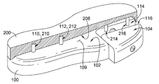
도 2는, 본 발명의 양태들에 따른, 수용 위치에서의 고정기구(100)를 도시한다. 구체적으로, 표면들이 횡단 방향으로 이격됨에 따른, 틈새가, 고정된 부분(102)의 제1 압축 표면(114)과 조절 가능 부분(104)의 제2 압축 표면(116) 사이에 도시된다. 압축 표면들은, 그들의 개별적인 고정된 부분 또는 조절 가능 부분과 같은 동일한 재료로 형성될 수 있을 것이다. 대안적으로, 돌출부들에 대해 더 높은 마찰 계수를 갖는 재료와 같은, 2차적 재료가, 하나 이상의 압축 표면과 함께 활용될 수 있다는 것이, 예상된다. 질감을 갖는 표면 또는 부드러운 표면이, 압축 표면들 중의 하나 이상에 형성될 수 있을 것이다. 조절 메커니즘(106)의 나사 형성 부분(107)이, 제공된다. 나사 형성 부분(107)은, 조절 가능 부분(104)의 고정된 부분(102)에 대한 슬라이딩 이동을 야기하기 위해, 고정된 부분(102) 및/또는 조절 가능 부분(104)과 회전 가능하게 맞물린다. Figure 2 shows a
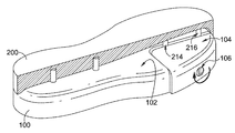
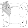
도 3은, 본 발명의 양태들에 따른, 예시적인 신발류 구성요소(200)를 도시한다. 구성요소(200)는, 신발 밑창과 같은, 하부 유닛일 수 있을 것이다. 신발 밑창은, 예시적인 양태에서, 바닥창, 중창, 또는 이들의 조합일 수 있을 것이다. 구성요소(200)는, 발가락측 단부(202), 뒤꿈치측 단부(204), 안쪽 측면(206), 바깥쪽 측면, 발-지향 표면(208), 지면-접촉 표면(218), 수용 부재(210, 212), 및 돌출부들(214, 216)을 포함한다. 구성요소의 임의의 크기, 형상, 스타일, 배열, 및 구성이, 예시적인 양태에서, 구성요소(200)를 위해 치환될 수 있다는 것이, 인식된다. 예를 들어, 이하의 도 9에 도시될 것으로서, 돌출부들 및/또는 수용 부재들은, 임의의 조합, 개소, 방향, 개수, 형상, 및/또는 크기의 것일 수 있을 것이다. 2개의 종방향으로 정렬된 돌출부(214, 216)가 도 3에 도시되지만, 이하의 도 8에 도시되는 것과 같은, 대안적인 배열이, 구현될 수 있을 것이다. 유사하게, 2개의 수용 부재(210, 212)가 구성요소(200)와 종방향 정렬 상태로 도시되지만, 이들이, 예시적인 양태에서, 서로로부터 또는 심지어 구성요소(200)의 종방향 축으로부터 횡단 방향으로 이격되게 놓일 수 있다는 것이, 예상된다. FIG. 3 illustrates an
발-지향 표면(208)은, 착용되는 구성에 놓일 때, 구성요소(200)의 상측 표면이다. 예를 들어, 발-지향 표면(208)은, 샌들 상면과 같은, 사용자가 그의/그녀의 발을 그 위에 두는, 발받침부로서 역할을 할 수 있을 것이다. 대안적으로, 발-지향 표면은, 코비어스 구두골(cobbler’s last)에 대해 신발 갑피를 형성할 때 사용되는 스트로벨 층(strobel layer)과 결합되는 (예를 들어, 접착되는, 봉재되는, 접합되는), 표면이다. 또한 추가로, 하나 이상의 층(예를 들어, 깔창, 안창, 중창)이, 착용될 때, 발-지향 표면(208)과 사용자의 발 사이에 배치될 수 있다는 것이, 예상된다.The foot-oriented
전통적으로, 착용자에게 불편함을 야기할 수 있으며 그리고 과잉의 재료를 사용할 수 있음에 따라, 돌출-형 요소가, 발-지향 표면(208) 상에 일체형으로 형성되지 않을 수 있을 것이다. 그러나, 예시적인 양태에서, 구성요소(200)의 형성 도중에, 이러한 예에서 돌출부들(214, 216)과 같은, 하나 이상의 돌출부가, 발-지향 표면(208)으로부터 돌출하도록 일체형으로 형성된다는 것이, 예상된다. 구성요소(200)는, 중합체-계열 재료[예를 들어, 에틸렌-비닐 아세테이트(EVA), 폴리우레탄(PU), 팽창된 열가소성 폴리우레탄(eTPU)]와 같은, 다양한 재료로 형성될 수 있을 것이다. 구성요소(200)를 형성하기 위한 금형이, 돌출부들 및/또는 수용 부재들을 일체형으로 형성하기 위한, 예시적인 양태에서 그러한 특징부들이 구성요소(200)의 형성 도중에 일체형으로 형성되는 것을 허용하는, 하나 이상의 구조를 포함할 수 있을 것이다. 대안적으로, 하나 이상의 후-생산 작업(예를 들어, 밀링, 접착, 기계적 삽입)이, 돌출부(들) 및/또는 수용 부재(들)를 형성하기 위해 신발류 구성요소 상에 실행될 수 있다는 것이, 예상된다.Traditionally, the protruding-type element may not be integrally formed on the foot-oriented
지면-접촉 표면(218)은, 착용될 때, 지면을 향하도록 의도되는 구성요소(200)의 표면이다. 하나 이상의 층이, 사용 중일 때 실제 지면과 지면-접촉 표면(218) 사이에 배치될 수 있다는 것이, 예상된다. 예를 들어, 하나 이상의 요소가, 구성요소(200)의 마모 저항성, 정지 마찰력, 심미감, 및 이와 유사한 것을 향상시키기 위해, 지면-접촉 표면에 접착될 수 있을 것이다. 추가로, 하나 이상의 프로세스가, 지면-접촉 표면(218) 상에 실행될 수 있다는 것이, 예상된다. 그에 따라, 돌출부들(214, 216)은, 고정기구(100)가, 구성요소(200)에 대해 고정될 때, 작업들을 실행하기 위해 하나 이상의 기계/장치로부터 지면-접촉 표면(218)을 가리지 않도록, 대향하는 발-지향 표면(208)으로부터 연장된다. 유사하게, 돌출부들(214, 216)은, 고정기구(100)가, 구성요소(200)에 대해 고정될 때, 지면-접촉 표면(218)과 발-지향 표면(208) 사이에서 연장되는 측벽들을 가리지 않도록, 발-지향 표면(208)으로부터 연장된다(예를 들어, 측벽들은, 안쪽 측면(206), 뒤꿈치측 단부(204), 발가락측 단부(202), 및 바깥쪽 측면을 형성한다). 측벽들 및 지면-접촉 표면(218)을 가리지 않도록 함에 의해, 고정기구(100)는, 양자 모두의 유형의 프로세스들이 실행될 때 고정기구들 또는 고정기구에 대한 위치들을 변경해야만 할 필요 없이, 양자 모두의 유형의 표면들 상에서 실행하는 작업들 사이의 이음매 없는 전이를 허용한다.The ground-contacting
구성요소(200)로부터 연장되는 돌출부들은, 원통형, 입방형, 및 이와 유사한 것과 같은, 임의의 형상의 것일 수 있을 것이다. 추가로, 이들은, 임의의 크기의 것일 수 있을 것이다. 예를 들어, 이들은, 핀(예를 들어, 0.5 밀리미터) 내지 5 cm의 폭(예를 들어, 직경)을 가질 수 있지만; 이들이, 예시적인 양태에서 5 cm 초과의 폭을 갖는다는 것이, 예상된다. 돌출부가, 임의의 길이의 것일 수 있을 것이다. 예를 들어, 이들은, 예시적인 양태에서, 1 cm 내지 10 cm의 길이를 가질 수 있을 것이다. 예를 들어, 돌출부들(214, 216)이, 0.5 cm 내지 2 cm 사이의 직경, 및 0.5 cm 내지 5 cm의 발-지향 표면(208)으로부터 연장되는 높이를 갖는 것이, 예상된다.The protrusions extending from
구성요소(200) 내로 연장되는 수용 부재들은, 원통형, 입방형, 및 이와 유사한 것과 같은, 임의의 형상의 것일 수 있을 것이다. 추가로, 이들은, 임의의 크기의 것일 수 있을 것이다. 예를 들어, 이들은, 핀(예를 들어, 0.5 밀리미터) 내지 5 cm의 폭(예를 들어, 직경)을 가질 수 있지만; 이들이, 예시적인 양태에서 5 cm 초과의 폭을 갖는다는 것이, 예상된다. 수용 부재가, 임의의 길이의 것일 수 있을 것이다. 예를 들어, 이들은, 예시적인 양태에서, 1 cm 내지 10 cm의 길이를 가질 수 있을 것이다. 예를 들어, 수용 부재들(210, 212)이, 0.5 cm 내지 2 cm 사이의 직경, 및 0.5 cm 내지 5 cm의 발-지향 표면(208)으로부터 구성요소(200) 내로 연장되는 높이를 갖는 것이, 예상된다. 수용 부재는, 성형 프로세스 도중에 형성될 수 있을 것이다. 예를 들어, 수용 부재는, 경화 핀(curing pin)의 사용으로부터 생성되는 것과 같은, 하부 유닛의 사출 성형 도중에 사용되는 구조물일 수 있을 것이다. 경화 핀은, 심지어 재료 두께 및/또는 형상에 관한 변동들을 가질 수 있는 물품의 경화를 가능하게 하기 위해, 성형된 물품의 부분들 내로 열 에너지를 유도한다. 그에 따라, 수용 부재들은, 성형 도중의 경화 핀들의 사용으로부터의 자취일 수 있을 것이다. 결과적으로, 고정기구 상의 대응하는 유지 부재들이, 예시적인 양태에서, 그러한 유지 부재들이 경화 핀들에 의해 형성되는 수용 부재들 내에 수용되는 것을 허용하는 개소들에서, 고정기구 상에 배치될 수 있을 것이다.The receiving members that extend into the
앞서 제공된 바와 같이, 돌출부들 및/또는 수용 부재들의 임의의 개수, 크기, 구성, 및 배열이, 예시적인 양태에서, 구성요소와 관련하여, 구현될 수 있다는 것이, 예상된다.It is contemplated that any number, size, configuration, and arrangement of protrusions and / or receiving members, as provided above, in the exemplary embodiment may be implemented with respect to the components.
도 4 내지 도 6은, 본 발명의 양태들에 따른, 도 3의 구성요소(200)를 도 1 및 도 2의 고정기구(100)와 함께 고정하는 일련의 단계들을 도시한다. 도 4는, 본 발명의 양태들에 따른, 돌출부들(214, 216)을 수용하기 위해 제1 압축 표면(114)과 제2 압축 표면(116) 사이에 틈새를 형성하는 수용 위치에서, 고정된 부분(102)과 조절 가능 부분(104)을 구비하는 고정기구(100)를 도시한다. 도 5는, 본 발명의 양태들에 따른, 고정기구(100)의 구성요소-접촉 표면(109)과 소통 상태에 놓이는 구성요소(300)의 발-지향 표면(208)을 도시한다. 도 5에 도시된 바와 같이, 유지 부재들(110, 112)은, 개별적으로, 수용 부재들(210, 212)에 의해 수용되며, 그리고 수용 부재들(210, 212)과 마찰식으로 맞물린다. 돌출부들(214, 216)은, 압축 표면들(114, 116) 사이에 수용된다. 예시적인 구성에서, 돌출부들(214, 216)은, 유지 부재들(110, 112)이 수용 부재들(210, 212)에 의해 수용되고 수용 부재들(210, 212)과 마찰식으로 맞물릴 때, 돌출부들(214, 216)이 제1 압축 표면(114)에 인접하게 (예를 들어, 제1 압축 표면과 접촉하거나 또는 5 밀리미터 이내에) 배치되도록, 구성요소(200) 상에 배치된다. 제2 압축 표면(116)으로부터의 거리가, 조절 가능 부분(104)이 유지 위치와 수용 위치 사이에서 전이됨에 따라, 변할 수 있을 것이다. 도 6은, 본 발명의 양태들에 따른, 돌출부들(214, 216)이 고정된 부분(102)과 조절 가능 부분(104) 사이에서 압축되도록 하는, 유지 위치에서의 고정기구(100)를 도시한다.Figures 4-6 illustrate a series of steps for securing the
도 7은, 본 발명의 양태들에 따른, 수용 부재들, 돌출부들, 및/또는 유지 부재들의 조정 구성을 구비하는, 고정기구(100) 및 구성요소(200)의 평면도를 도시한다. 도 8은, 본 발명의 양태들에 따른, 대안적인 고정기구(101) 및 구성요소(201)의 평면도를 도시한다. 도 8의 이러한 예에서, 고정기구(101)는, 고정기구(101)에 대해 종단 방향으로 이동 가능한 조절 가능 부분(105)을 갖도록 구성된다. 조절 가능 부분(105)은, 발가락 영역의 적어도 일부분을, 구체적으로 발가락측 단부를 형성한다. 고정된 부분(103)이, 발가락 영역으로부터 뒤꿈치측 단부로 연장된다. 제1 압축 표면(115) 및 제2 압축 표면(117)이, 고정기구(101)의 횡단 폭을 가로질러 연장된다. 도 8에서의 이러한 배열은, 도 7의 구성과 비교할 때, 조절 가능 부분의 직교 운동을 제공한다. 도 8에서의 압축 표면들(115, 117)의 횡단 연장 때문에, 구성요소(201)는, 횡단 방향으로 이격된 돌출부들(215, 217)을 갖도록 구성된다. 고정기구(101)의 요소들(111, 113)이, 예시적인 양태에서, 돌출부들 또는 구멍들일 수 있는, 유지 부재들이다. 요소들(211, 213)은, 요소들(111, 113)의 구성에 대응하여, 수용 부재들 또는 돌출부들로 상응하게 구성된다.Figure 7 shows a top view of a
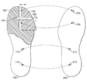
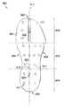
도 9는, 본 발명의 양태들에 따른, 예시적인 고정기구(900)의 평면도를 도시한다. 고정기구(900)는, 본 발명의 양태들에 따라, 발가락측 단부(902), 뒤꿈치측 단부(904), 안쪽 측면(906), 바깥쪽 측면(908), 발가락 영역(910), 중족 영역(912), 뒤꿈치 영역(914), 종방향 축(916), 2개의 유지 부재(920, 924) 사이에서 연장되는 유지 부재 축(918), 및 복수의 다른 유지 부재(922)를 구비한다. 종방향 축(916)은, 발가락측 단부(902)로부터 뒤꿈치측 단부(904)로 연장된다. 발가락 영역(910)은, 안쪽 측면(906)의 발가락-단부 정점을 포함하고, 중족 영역(912)은, 안쪽 측면(906)의 최하점을 포함하며, 그리고 뒤꿈치 영역(914)은, 안쪽 측면(906)의 뒤꿈치-단부 정점을 포함한다.Figure 9 shows a top view of an
복수의 유지 부재(922)는, 예시적인 양태에서, 돌출부들 및/또는 구멍들일 수 있을 것이다. 복수의 유지 부재(922)의 관계는, 유지 부재들(920, 924) 사이에서 연장되는 유지 부재 축(918)에 의해 도시되는 것과 같은, 종방향 축(916)과 평행한 종단 방향 정렬을 포함할 수 있을 것이다. 대안적으로 및/또는 부가적으로, 유지 부재들은, 서로 횡단 방향으로 이격될 수 있으며, 그리고 예시적인 양태에서, 종방향 축(916)에 대해 횡단 방향으로 배치될 수 있을 것이다. 도시된 바와 같이, 임의의 개수의 유지 부재가, 복수의 유지 부재(922)를 형성할 수 있을 것이다. 더불어, 유지 부재들은, 고정기구의 임의의 구역들에 배치될 수 있을 것이다.The plurality of retaining
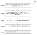
도 10은, 본 발명의 양태들에 따른, 고정기구 상에서 신발류 구성요소를 처리하는 방법을 나타내는 흐름도(1000)를 도시한다. 블록(1002)에서, 신발류 구성요소의 돌출부가, 고정기구의 제1 압축 표면과 제2 압축 표면 사이에 삽입된다. 예시적인 양태에서, 돌출부는, 구성요소의 발-지향 표면으로부터 연장된다. 부가적으로, 예시적인 양태에서, 제1 압축 표면은, 고정기구의 고정된 부분의 표면이며, 그리고 제2 압축 표면은, 고정기구의 조절 가능 부분의 표면이다.Figure 10 shows a
블록(1004)에서, 고정기구의 조절 가능 부분은, 고정기구에 대해 신발류 구성요소를 유지하기 위해, 고정기구의 고정된 부분을 향해 이동하게 된다. 예를 들어, 조절 가능 부분의 이동은, 그들 사이의 마찰 맞물림이 고정기구에 대한 구성요소의 이동을 제한하도록, 고정된 부분과 조절 가능 부분 사이에서 신발류 구성요소의 돌출부들을 압축할 수 있을 것이다. 조절 가능 부분의 이동은, 고정된 부분에 대해 슬라이딩 이동하도록 조절 가능 부분의 선형 이동으로 변환되는, 조절 메커니즘의 회전력에 의해 야기될 수 있을 것이다.At block 1004, the adjustable portion of the fixture mechanism is moved toward a fixed portion of the fixture mechanism to hold the footwear component relative to the fixture mechanism. For example, movement of the adjustable portion may compress the protrusions of the footwear component between the fixed portion and the adjustable portion such that a friction engagement therebetween limits the movement of the component relative to the fixture. Movement of the adjustable portion may be caused by the rotational force of the adjustment mechanism, which is translated into a linear movement of the adjustable portion to slidingly move relative to the fixed portion.
블록(1006)에서, 신발류 구성요소는 처리된다. 예를 들어, 신발류 구성요소를 유지하는 고정기구는, 신발류 구성요소 상에 작업을 실행하는 기계에 대해 배치될 수 있을 것이다. 고정기구가 고정된 부분에 대해 알려진 크기 및 형상이기 때문에, 이동 메커니즘은, 고정기구를 위치 설정할 수 있으며, 그리고 그에 따라, 신발류 구성요소는, 그에 대해, 실행될 작업을 위한 알려진 개소에, 고정된다. 예를 들어, 일련의 레이저-형성 사이프들이 신발류 구성요소 내에 형성되어야 하는 경우, 신발류 구성요소는, 예시적인 양태에서, 규정된 사이핑 패턴을 달성하기 위해 레이저 에너지원에 대해 이동하게 될 수 있다.At
블록(1008)에서, 조절 가능 부분은, 고정된 부분으로부터, 블록(1010)에서 제공되는 바와 같은, 제1 압축 표면과 제2 압축 표면 사이에서 돌출부들의 제거를 허용하는, 수용 위치로 멀어지게 이동하게 될 수 있을 것이다.At block 1008, the adjustable portion is moved away from the fixed portion, away from the fixed position, to allow removal of the protrusions between the first and second compression surfaces, as provided in block 1010, .
상기한 바로부터, 본 발명이, 명백하며 그리고 구조에 내재된 다른 이점들과 함께 기술되는, 상기한 모든 목표들 및 목적들을 달성하기에 잘 어울리는 것임을, 알게 될 것이다.From the foregoing, it will be appreciated that the present invention is well suited to achieving all of the above objects and objects, which are set forth with particularity and in combination with other advantages inherent in the structure.
특정 특징들 및 하위 조합들이 유용하며 그리고 다른 특징들 및 하위 조합들을 참조하지 않고 사용될 수 있다는 것이 이해될 것이다. 이는, 청구항들에 의해 예상되며 그리고 청구항들의 범위 이내에 놓인다.It will be appreciated that certain features and subcombinations are useful and can be used without reference to other features and subcombinations. This is anticipated by the claims and lies within the scope of the claims.
특정의 요소들 및 단계들이 서로에 관해 논의되지만, 여기에서 제공되는 임의의 요소 및/또는 단계들이, 여전히 여기에서 제공되는 범위 이내에 속하는 가운데, 그에 대한 명시적 제공과 무관하게, 임의의 다른 요소 및/또는 단계들과 조합 가능한 것으로 예상된다는 것이 이해된다. 많은 가능한 실시예들이 본 발명의 범위로부터 벗어남 없이 개시될 수 있기 때문에, 여기에 기술되거나 첨부 도면에 도시되는 모든 대상이, 예시적으로 그리고 제한하는 의미가 아닌 것으로 해석되어야 한다는 것을, 이해해야 한다.It is to be understood that although certain elements and steps may be discussed with respect to one another, it should be understood that any element and / or steps provided herein, whether within the scope of what is still provided herein, / RTI > and / or < / RTI > It is to be understood that, since many possible embodiments may be disclosed without departing from the scope of the invention, all objects described herein or illustrated in the accompanying drawings are to be interpreted as illustrative and not restrictive.
본 명세서에서 그리고 이후에 열거되는 청구항들과 관련되어 사용되는 바와 같은, 전문용어 "청구항들 중의 어느 항" 또는 상기 전문용어의 유사한 변형형들은, 청구항들의 특징부들이 임의의 조합으로 조합될 수 있게 해석되도록 의도된다. 예를 들어, 예시적인 청구항 4는, 청구항 1 및 청구항 4의 특징부들이 조합될 수 있고, 청구항 2 및 청구항 4의 요소들이 조합될 수 있으며, 청구항 3 및 청구항 4의 요소들이 조합될 수 있고, 청구항 1, 청구항 2 및 청구항 4의 요소들이 조합될 수 있으며, 청구항 2, 청구항 3 및 청구항 4의 요소들이 조합될 수 있고, 청구항 1, 청구항 2, 청구항 3 및 청구항 4의 요소들이 조합될 수 있으며, 및/또는 다른 변형형도 가능한 것으로 해석되도록 의도되는, 청구항 1 내지 청구항 3 중의 어느 한 항의 방법/장치를 지시할 수 있을 것이다. 더불어, 전문용어 "청구항들 중의 어느 항" 또는 상기 전문용어의 유사한 변형형들은, 이상에 제공되는 예들 중의 일부에 의해 지시되는 바와 같이, "청구항 들 중의 어느 한 항" 또는 그러한 전문용어의 다른 변형형들을 포함하는 것으로 의도된다. It is to be understood that the terminology "any of the claims" or similar variants of the terminology, as used in connection with the claims hereafter and in the following, should be construed as encompassing any way that the features of the claims may be combined in any combination It is intended to be interpreted. For example, in an exemplary claim 4, the features of
Claims (23)
제1 압축 표면을 갖는 고정된 부분; 제2 압축 표면을 갖는 조절 가능 부분으로서, 조절 가능 부분은, 적어도, 신발류 구성요소 제조용 고정기구에 대해 신발류 구성요소를 유지하기 위한, 유지 위치와 수용 위치 사이에서, 상기 고정된 부분에 이동 가능하게 결합되고, 상기 제1 압축 표면은, 상기 수용 위치에 놓일 때보다 상기 유지 위치에서, 상기 제2 압축 표면에 대해 더 가깝게 인접하게 되는 것인, 조절 가능 부분; 상기 고정된 부분과 상기 조절 가능 부분 사이에서 연장되는 조절 메커니즘으로서, 부분적으로, 상기 고정된 부분과 상기 조절 가능 부분 사이의 이동 가능한 결합을 제공하는 것인, 조절 메커니즘을 포함하는 것인, 신발류 구성요소 제조용 고정기구.Fixing equipment for the manufacture of footwear components:
A fixed portion having a first compression surface; An adjustable portion having a second compression surface, the adjustable portion comprising at least a retaining portion for retaining a footwear component relative to a securing mechanism for the manufacture of a footwear component, Wherein the first compression surface is adjacent to the second compression surface in the retention position more closely than when it is in the receiving position; An adjustment mechanism extending between the fixed portion and the adjustable portion to provide a movable coupling between the fixed portion and the adjustable portion in part. Fixing devices for manufacturing elements.
상기 고정된 부분은, 제1 유지 부재를 포함하는 것인, 신발류 구성요소 제조용 고정기구.The method according to claim 1,
Wherein the fixed portion comprises a first retaining member. ≪ RTI ID = 0.0 > 11. < / RTI >
상기 제1 유지 부재는 구성요소-지향 표면으로부터 연장되는 돌출부이거나, 또는 상기 제1 유지 부재는 구성요소-지향 표면으로부터 상기 고정된 부분 내로 연장되는 구멍인 것인, 신발류 구성요소 제조용 고정기구.3. The method of claim 2,
Wherein the first retaining member is a protrusion extending from the component-oriented surface, or the first retaining member is a hole extending from the component-oriented surface into the fixed portion.
상기 제1 유지 부재는, 상기 신발류 구성요소 제조용 고정기구의 뒤꿈치 영역, 상기 신발류 구성요소 제조용 고정기구의 중족 영역, 또는 상기 신발류 구성요소 제조용 고정기구의 발가락 영역 중의 하나 내에 배치되는 것인, 신발류 구성요소 제조용 고정기구.The method according to claim 2 or 3,
Wherein the first retaining member is disposed within one of a heel region of a fixture for manufacturing the footwear component, a heel region of the fixture for manufacturing the footwear component, or a toe region of the fixture for manufacturing the footwear component, Fixing devices for manufacturing elements.
제2 유지 부재를 더 포함하는 것인, 신발류 구성요소 제조용 고정기구.5. The method according to any one of claims 2 to 4,
And further comprising a second retaining member.
상기 제1 유지 부재 및 상기 제2 유지 부재는, 구성요소-지향 표면으로부터 연장되는 돌출부 또는 상기 구성요소-지향 표면 내로 연장되는 구멍 중의 하나인 것인, 신발류 구성요소 제조용 고정기구.6. The method of claim 5,
Wherein the first retaining member and the second retaining member are one of a protrusion extending from the component-oriented surface or a hole extending into the component-oriented surface.
상기 제1 유지 부재는, 뒤꿈치 영역 내에 배치되며, 그리고 상기 제2 유지 부재는, 상기 고정된 부분의 중족 영역 내에 배치되는 것인, 신발류 구성요소 제조용 고정기구.The method according to claim 5 or 6,
Wherein the first retaining member is disposed within the heel region and the second retaining member is disposed within the caulk region of the fixed portion.
상기 제1 유지 부재와 상기 제2 유지 부재 사이에서 연장되는 축이, 상기 신발류 구성요소 제조용 고정기구의 종방향 축과 평행한 것인, 신발류 구성요소 제조용 고정기구.8. The method according to any one of claims 5 to 7,
Wherein a shaft extending between the first and second holding members is parallel to the longitudinal axis of the anchoring mechanism for the footwear component.
상기 제2 유지 부재는, 상기 제1 유지 부재로부터 횡단 방향으로 이격되는 것인, 신발류 구성요소 제조용 고정기구.9. The method according to any one of claims 1 to 8,
Wherein the second retaining member is transversely spaced from the first retaining member.
상기 조절 가능 부분은, 상기 신발류 구성요소 제조용 고정기구의 발가락 영역의 일부분을 형성하는 것인, 신발류 구성요소 제조용 고정기구.10. The method according to any one of claims 1 to 9,
Wherein the adjustable portion defines a portion of the toe region of the anchoring mechanism for manufacturing the footwear component.
상기 조절 가능 부분은, 상기 고정된 부분에 대해 횡단 방향으로 이동 가능한 것인, 신발류 구성요소 제조용 고정기구.11. The method according to any one of claims 1 to 10,
Wherein the adjustable portion is movable in a transverse direction relative to the fixed portion.
상기 조절 가능 부분은, 상기 고정된 부분에 대해 종단 방향으로 이동 가능한 것인, 신발류 구성요소 제조용 고정기구.12. The method according to any one of claims 1 to 11,
Wherein the adjustable portion is movable in the longitudinal direction relative to the fixed portion.
상기 제1 압축 표면 및 상기 제2 압축 표면은, 평행한 표면들인 것인, 신발류 구성요소 제조용 고정기구.13. The method according to any one of claims 1 to 12,
Wherein the first compression surface and the second compression surface are parallel surfaces.
상기 제1 압축 표면은, 상기 신발류 구성요소 제조용 고정기구의 종방향 축과 평행한 방향으로 연장되는 것인, 신발류 구성요소 제조용 고정기구.14. The method according to any one of claims 1 to 13,
Wherein the first compression surface extends in a direction parallel to the longitudinal axis of the anchoring mechanism for securing the footwear component.
상기 고정된 부분은, 제1 구성요소-접촉 표면을 구비하며, 그리고 상기 조절 가능 부분은, 제2 구성요소-접촉 표면을 구비하고, 상기 유지 위치에 놓일 때, 상기 제1 압축 표면에 인접한 상기 제1 구성요소-접촉 표면 및 상기 제2 압축 표면에 인접한 상기 제2 구성요소-접촉 표면은, 동등한 높이에 놓이는 것인, 신발류 구성요소 제조용 고정기구.15. The method according to any one of claims 1 to 14,
Wherein the fixed portion has a first component-contacting surface and the adjustable portion has a second component-contacting surface and, when in the holding position, Wherein the first component-contact surface and the second component-contact surface adjacent the second compression surface are at an equal height.
상기 조절 메커니즘은, 상기 조절 메커니즘의 회전 운동이 적어도 상기 유지 위치와 상기 수용 위치 사이의 조절 가능한 이동을 제공하도록, 상기 고정된 부분 또는 상기 조절 가능 부분 중의 적어도 하나에 의해 맞물리게 되는 나사 형성 표면을 포함하는 것인, 신발류 구성요소 제조용 고정기구. 16. The method according to any one of claims 1 to 15,
The adjustment mechanism includes a threaded surface that is engaged by at least one of the fixed portion or the adjustable portion such that the rotational movement of the adjustment mechanism provides an adjustable movement between at least the holding position and the receiving position Wherein said fastening means comprises:
상기 조절 가능 부분은, 그를 통해 횡단 방향으로 연장되는 조절 구멍을 구비하며, 그리고 상기 조절 메커니즘은, 상기 조절 구멍을 통해 연장되는 것인, 신발류 구성요소 제조용 고정기구.17. The method according to any one of claims 1 to 16,
Wherein the adjustable portion has an adjusting aperture extending therethrough in a transverse direction therethrough and the adjusting mechanism extends through the adjusting aperture.
상기 조절 메커니즘은, 상기 조절 메커니즘의 선형 운동이 상기 유지 위치에서 상기 조절 가능 부분을 해제 가능하게 유지하도록, 상기 고정된 부분 또는 상기 조절 가능 부분 중의 적어도 하나에 의해 맞물리게 되는 늑골형 표면(ribbed surface)을 포함하는 것인, 신발류 구성요소 제조용 고정기구.18. The method according to any one of claims 1 to 17,
Wherein the adjustment mechanism comprises a ribbed surface engaging by at least one of the fixed portion or the adjustable portion such that the linear movement of the adjustment mechanism releasably retains the adjustable portion at the retention position, Wherein the fastening member comprises a fastening member for fastening the footwear component.
상기 고정기구의 고정된 부분의 제1 압축 표면과 상기 고정기구의 조절 가능 부분의 제2 압축 표면 사이에 상기 신발류 구성요소의 제1 돌출부를 삽입하는 단계로서, 상기 제1 돌출부는, 상기 신발류 구성요소의 발-지향 표면으로부터 연장되는 것인, 제1 돌출부를 삽입하는 단계; 상기 제1 압축 표면 및 상기 제2 압축 표면이, 상기 고정기구가 상기 고정기구에 대해 상기 신발류 구성요소를 유지하는 것을 허용하기 위해, 상기 제1 돌출부와 접촉하도록, 상기 조절 가능 부분을 상기 고정된 부분을 향해 슬라이딩 이동시키는 단계; 상기 고정기구에 의해 유지될 때 상기 신발류 구성요소를 처리하는 단계; 상기 신발류 구성요소를 처리하는 단계에 이어서, 상기 제1 압축 표면 및 상기 제2 압축 표면이 상기 제1 돌출부와 맞물림 해제되도록, 상기 조절 가능 부분을 상기 고정된 부분으로부터 멀어지게 슬라이딩 이동시키는 단계; 및 상기 제1 돌출부를 상기 제1 압축 표면과 상기 제2 압축 표면 사이로부터 제거하는 단계를 포함하는 것인, 신발류 구성요소 처리 방법.CLAIMS What is claimed is: 1. A method of treating a footwear component on a fixture comprising:
Inserting a first projection of the footwear component between a first compression surface of a fixed portion of the fixation mechanism and a second compression surface of an adjustable portion of the fixation mechanism, Extending from the foot-oriented surface of the element; Wherein the first compression surface and the second compression surface are adapted to contact the first protrusion so as to allow the securing mechanism to retain the footwear component relative to the securing mechanism, Slidably moving a portion of the substrate; Treating the footwear component when held by the securing mechanism; Following the step of processing the footwear component, sliding the adjustable portion away from the fixed portion such that the first compression surface and the second compression surface are disengaged from the first projection; And removing said first projection from between said first compression surface and said second compression surface.
상기 고정된 부분으로부터 연장되는 복수의 유지 부재를 상기 신발류 구성요소 내로 삽입하는 단계를 더 포함하는 것인, 신발류 구성요소 처리 방법.20. The method of claim 19,
Further comprising inserting a plurality of retaining members extending from the fixed portion into the footwear component.
상기 조절 가능 부분을 상기 고정된 부분을 향해 슬라이딩 이동시키기 위해 조절 메커니즘을 회전시키는 단계를 더 포함하는 것인, 신발류 구성요소 처리 방법.21. The method according to claim 19 or 20,
And rotating the adjustment mechanism to slidably move the adjustable portion toward the fixed portion.
상기 제1 압축 표면과 상기 제2 압축 표면 사이에 상기 신발류 구성요소의 제2 돌출부를 삽입하는 단계를 더 포함하고, 상기 제2 돌출부는 상기 신발류 구성요소의 상기 발-지향 표면으로부터 연장되는 것인, 신발류 구성요소 처리 방법.22. The method according to any one of claims 19 to 21,
Further comprising inserting a second protrusion of the footwear component between the first compression surface and the second compression surface, the second protrusion extending from the foot-oriented surface of the footwear component , Footwear component processing method.
신발류 구성요소를 처리하는 단계는, 뒤따르는 프로세스들로부터 선택되는 하나 이상의 프로세스를 포함하는 것인, 신발류 구성요소 처리 방법:
(1) 절단; (2) 표면 마감을 적용; (3) 사이프들을 형성; (4) 연마; (5) 접착제를 도포; (6) 스캐닝; (7) 펀칭; 또는 (8) 엠보싱.23. The method according to any one of claims 19 to 22,
Wherein the step of processing the footwear component comprises one or more processes selected from the following processes:
(1) cutting; (2) applying surface finish; (3) forming sieves; (4) polishing; (5) applying an adhesive; (6) scanning; (7) punching; Or (8) embossing.
Applications Claiming Priority (3)
| Application Number | Priority Date | Filing Date | Title |
|---|---|---|---|
| US201562272520P | 2015-12-29 | 2015-12-29 | |
| US62/272,520 | 2015-12-29 | ||
| PCT/US2016/069163 WO2017117374A1 (en) | 2015-12-29 | 2016-12-29 | Footwear component manufacturing fixture |
Publications (2)
| Publication Number | Publication Date |
|---|---|
| KR20180098349A true KR20180098349A (en) | 2018-09-03 |
| KR102115869B1 KR102115869B1 (en) | 2020-05-28 |
Family
ID=57799934
Family Applications (1)
| Application Number | Title | Priority Date | Filing Date |
|---|---|---|---|
| KR1020187021322A Active KR102115869B1 (en) | 2015-12-29 | 2016-12-29 | Fixture for manufacturing footwear components |
Country Status (6)
| Country | Link |
|---|---|
| US (2) | US10905200B2 (en) |
| EP (1) | EP3397105B1 (en) |
| KR (1) | KR102115869B1 (en) |
| CN (1) | CN108471842B (en) |
| MX (1) | MX2018008088A (en) |
| WO (1) | WO2017117374A1 (en) |
Families Citing this family (1)
| Publication number | Priority date | Publication date | Assignee | Title |
|---|---|---|---|---|
| US10905200B2 (en) | 2015-12-29 | 2021-02-02 | Nike, Inc. | Footwear component manufacturing fixture |
Citations (5)
| Publication number | Priority date | Publication date | Assignee | Title |
|---|---|---|---|---|
| WO1993005675A1 (en) * | 1991-09-26 | 1993-04-01 | U.S.A. Retama, Inc. | Shoe sole component and shoe sole component construction method |
| EP1125514A2 (en) * | 2000-02-18 | 2001-08-22 | Autec di Geri Ing. Fabrizio & C.s.a.s | Apparatus for the automatic trimming of plastic shoe soles and relevant trimming method |
| WO2013024498A1 (en) * | 2011-08-12 | 2013-02-21 | Stamplast Pr S.A.S. Di Pellacini Roberto E C. | Precision vice |
| JP2016055153A (en) * | 2014-09-11 | 2016-04-21 | 株式会社千鳥屋宗家 | Shoe shape retainer and auxiliary tool for shoe shape retainer |
| US20160150856A1 (en) * | 2014-01-07 | 2016-06-02 | Nike, Inc. | System for shoe sole portion painting |
Family Cites Families (43)
| Publication number | Priority date | Publication date | Assignee | Title |
|---|---|---|---|---|
| US2892200A (en) * | 1959-06-30 | Clamp for heel doweling machines | ||
| US1573045A (en) * | 1920-10-02 | 1926-02-16 | United Shoe Machinery Corp | Work support |
| US1695321A (en) * | 1924-05-29 | 1928-12-18 | United Shoe Machinery Corp | Work-holding device |
| US1674061A (en) * | 1925-01-09 | 1928-06-19 | United Shoe Machinery Corp | Work-positioning means |
| US1710162A (en) * | 1928-03-07 | 1929-04-23 | Guido Marco | Shoe press |
| US1710718A (en) * | 1928-05-16 | 1929-04-30 | Diamond Specialty Mfg Company | Shoe-heel-attaching jack |
| US1724355A (en) * | 1928-07-23 | 1929-08-13 | F & P Heel Holder Company | Shoe-heel holder |
| US1987638A (en) * | 1929-01-12 | 1935-01-15 | Littleway Process Co | Means for holding shoe uppers in lasted position |
| US1837728A (en) * | 1929-05-10 | 1931-12-22 | Rattazzi John | Clamp and shoe last vise |
| US1820492A (en) * | 1929-08-17 | 1931-08-25 | Rattazzi John | Clamp and shoe last vise |
| US1855787A (en) * | 1930-08-14 | 1932-04-26 | Goodrich Co B F | Last supporting device |
| US1854591A (en) * | 1931-05-01 | 1932-04-19 | Leddy James | Shoe repairing jack |
| US2035549A (en) * | 1932-02-09 | 1936-03-31 | United Shoe Machinery Corp | Shoe-supporting mechanism |
| US1991462A (en) * | 1932-02-11 | 1935-02-19 | United Shoe Machinery Corp | Filler device for shoes |
| US1922750A (en) * | 1932-05-03 | 1933-08-15 | Dionisie I Salcaian | Shoe jack |
| US1954178A (en) * | 1932-05-28 | 1934-04-10 | Kakides Harry | Jack |
| US1907607A (en) * | 1932-06-11 | 1933-05-09 | William E Strobel | Standard for shoemakers' lasts |
| US1928847A (en) * | 1933-02-25 | 1933-10-03 | Bates Kenneth | Shoe last |
| US2007616A (en) * | 1933-04-15 | 1935-07-09 | Meldon A Shaffner | Heel clamping device |
| US2086836A (en) * | 1937-01-06 | 1937-07-13 | Howard H Anderson | Shoe tip stretcher |
| US2145311A (en) * | 1937-07-23 | 1939-01-31 | Howe Machinery Co Inc | Shoemaker's jack |
| US2191230A (en) * | 1939-03-01 | 1940-02-20 | Guss Isadore | Device for putting new toe coverings on shoes |
| US2237161A (en) * | 1939-05-09 | 1941-04-01 | Goodrich Co B F | Shoe repair press |
| GB558340A (en) | 1942-01-26 | 1943-12-31 | Us Rubber Co | Improvements in shoes |
| US2503487A (en) * | 1947-03-03 | 1950-04-11 | Gertrude A Holmgren | Lasting machine |
| US4909768A (en) * | 1988-08-26 | 1990-03-20 | Brien Herbert J O | Arch adjusting mechanism for water ski boots |
| DE3837516A1 (en) * | 1988-11-04 | 1990-05-10 | Pfaff Ind Masch | WORKSHOP FOR PREPARING A LARGE COMPOSITE WORKPIECE |
| US5875504A (en) * | 1996-04-04 | 1999-03-02 | Tambling; Michael Ronald | Device for enlarging a region of a boot or shoe |
| US5701685A (en) * | 1997-01-23 | 1997-12-30 | Mariner J. Pezza | Triple-action, adjustable, rebound device |
| US6438872B1 (en) * | 1999-11-12 | 2002-08-27 | Harry Miller Co., Inc. | Expandable shoe and shoe assemblies |
| CN2410899Y (en) | 2000-03-06 | 2000-12-20 | 叶寿涂 | An anti-slip device for a rotary table of a shoe-making leveling machine |
| US6393736B1 (en) * | 2000-05-25 | 2002-05-28 | Greer Reed Biomedical, Llc | Adjustable brace orthotic and method of treating plantar fasciitis and related foot disorders |
| DE102006059658B3 (en) * | 2006-12-18 | 2008-03-27 | Adidas International Marketing B.V. | Shoe e.g. sports shoe, has lever comprising arm connected with deforming element e.g. spiral spring, and another arm connected with sole surface and sole shell, where lever at intersection of arms is rotatably supported at sole shell |
| US20110047826A1 (en) * | 2009-08-25 | 2011-03-03 | Rosen Henri E | Girthwise adjustable shoe construction |
| CA2879080A1 (en) * | 2011-07-13 | 2013-01-17 | Pics On Kicks, Llc | System and method for printing customized graphics on footwear and other articles of clothing |
| KR101177870B1 (en) | 2012-04-27 | 2012-08-29 | 유성엽 | Footwear with a switchable upper or sole |
| US9848669B2 (en) * | 2012-06-19 | 2017-12-26 | Shimano Inc. | Bicycle cleat positioining device |
| US9089183B2 (en) * | 2012-05-30 | 2015-07-28 | Shimano Inc. | Bicycle cleat positioning kit |
| US9585438B2 (en) * | 2013-02-22 | 2017-03-07 | Nike, Inc. | System and method for forming an article |
| WO2015025398A1 (en) | 2013-08-22 | 2015-02-26 | 株式会社アシックス | Article production system, article production method, and pallet |
| US9706815B2 (en) * | 2014-01-30 | 2017-07-18 | Nike, Inc. | Paint fixture for shoe portions |
| CN203988539U (en) | 2014-06-25 | 2014-12-10 | 张丽 | The sagging early stage correcting unit of adjustable foot |
| US10905200B2 (en) | 2015-12-29 | 2021-02-02 | Nike, Inc. | Footwear component manufacturing fixture |
-
2016
- 2016-11-30 US US15/365,374 patent/US10905200B2/en active Active
- 2016-12-29 EP EP16826659.1A patent/EP3397105B1/en active Active
- 2016-12-29 WO PCT/US2016/069163 patent/WO2017117374A1/en not_active Ceased
- 2016-12-29 KR KR1020187021322A patent/KR102115869B1/en active Active
- 2016-12-29 MX MX2018008088A patent/MX2018008088A/en unknown
- 2016-12-29 CN CN201680077112.4A patent/CN108471842B/en active Active
-
2020
- 2020-12-24 US US17/133,800 patent/US11369168B2/en active Active
Patent Citations (5)
| Publication number | Priority date | Publication date | Assignee | Title |
|---|---|---|---|---|
| WO1993005675A1 (en) * | 1991-09-26 | 1993-04-01 | U.S.A. Retama, Inc. | Shoe sole component and shoe sole component construction method |
| EP1125514A2 (en) * | 2000-02-18 | 2001-08-22 | Autec di Geri Ing. Fabrizio & C.s.a.s | Apparatus for the automatic trimming of plastic shoe soles and relevant trimming method |
| WO2013024498A1 (en) * | 2011-08-12 | 2013-02-21 | Stamplast Pr S.A.S. Di Pellacini Roberto E C. | Precision vice |
| US20160150856A1 (en) * | 2014-01-07 | 2016-06-02 | Nike, Inc. | System for shoe sole portion painting |
| JP2016055153A (en) * | 2014-09-11 | 2016-04-21 | 株式会社千鳥屋宗家 | Shoe shape retainer and auxiliary tool for shoe shape retainer |
Also Published As
| Publication number | Publication date |
|---|---|
| US11369168B2 (en) | 2022-06-28 |
| WO2017117374A1 (en) | 2017-07-06 |
| KR102115869B1 (en) | 2020-05-28 |
| CN108471842B (en) | 2021-05-25 |
| MX2018008088A (en) | 2018-08-23 |
| US20210112927A1 (en) | 2021-04-22 |
| US20170181502A1 (en) | 2017-06-29 |
| US10905200B2 (en) | 2021-02-02 |
| CN108471842A (en) | 2018-08-31 |
| EP3397105B1 (en) | 2022-05-18 |
| EP3397105A1 (en) | 2018-11-07 |
Similar Documents
| Publication | Publication Date | Title |
|---|---|---|
| CN112790470B (en) | Sole structure with auxetic structure and sipes | |
| CN106163312B (en) | Method of manufacturing a sole assembly formed from a plurality of preforms | |
| US10674789B2 (en) | Sole structure for an article of footwear with spaced recesses | |
| EP2079577B1 (en) | Method of producing footwear | |
| US9744734B2 (en) | Sole assembly with plural portions that cooperatively define chamber | |
| BRPI1015103B1 (en) | footwear manufacturing process with grooves | |
| US9743711B2 (en) | Sole assembly with plural portions that cooperatively define chamber | |
| EP2337675B1 (en) | Stock fit assembly fixture for shoe production | |
| CN112074206B (en) | Article with auxetic space and method of manufacture | |
| TW201818845A (en) | Multi-component sole structure having an auxetic configuration | |
| KR20180098349A (en) | Fixtures for the manufacture of footwear components | |
| CN106965472B (en) | The preparation method of rubber boots | |
| CN106174869B (en) | Press fitting fixing device for manufacturing article of footwear | |
| KR20170019952A (en) | And a method for manufacturing shoes with the shock-absorbing function, and pressure | |
| CN211154071U (en) | Sole processingequipment is used in shoes processing | |
| KR100987361B1 (en) | Shoe midsole manufacturing method and shoe midsole | |
| EP4046519A1 (en) | Footwear bottom with composite structure and process for the manufacturing of said bottom | |
| KR20120084619A (en) | Insole for shoes | |
| IE60607B1 (en) | A method of manufacturing boots |
Legal Events
| Date | Code | Title | Description |
|---|---|---|---|
| A201 | Request for examination | ||
| P11-X000 | Amendment of application requested |
St.27 status event code: A-2-2-P10-P11-nap-X000 |
|
| P13-X000 | Application amended |
St.27 status event code: A-2-2-P10-P13-nap-X000 |
|
| PA0105 | International application |
St.27 status event code: A-0-1-A10-A15-nap-PA0105 |
|
| PA0201 | Request for examination |
St.27 status event code: A-1-2-D10-D11-exm-PA0201 |
|
| PG1501 | Laying open of application |
St.27 status event code: A-1-1-Q10-Q12-nap-PG1501 |
|
| E902 | Notification of reason for refusal | ||
| PE0902 | Notice of grounds for rejection |
St.27 status event code: A-1-2-D10-D21-exm-PE0902 |
|
| E13-X000 | Pre-grant limitation requested |
St.27 status event code: A-2-3-E10-E13-lim-X000 |
|
| P11-X000 | Amendment of application requested |
St.27 status event code: A-2-2-P10-P11-nap-X000 |
|
| P13-X000 | Application amended |
St.27 status event code: A-2-2-P10-P13-nap-X000 |
|
| E701 | Decision to grant or registration of patent right | ||
| PE0701 | Decision of registration |
St.27 status event code: A-1-2-D10-D22-exm-PE0701 |
|
| GRNT | Written decision to grant | ||
| PR0701 | Registration of establishment |
St.27 status event code: A-2-4-F10-F11-exm-PR0701 |
|
| PR1002 | Payment of registration fee |
St.27 status event code: A-2-2-U10-U12-oth-PR1002 Fee payment year number: 1 |
|
| PG1601 | Publication of registration |
St.27 status event code: A-4-4-Q10-Q13-nap-PG1601 |
|
| PR1001 | Payment of annual fee |
St.27 status event code: A-4-4-U10-U11-oth-PR1001 Fee payment year number: 4 |
|
| PR1001 | Payment of annual fee |
St.27 status event code: A-4-4-U10-U11-oth-PR1001 Fee payment year number: 5 |
|
| PR1001 | Payment of annual fee |
St.27 status event code: A-4-4-U10-U11-oth-PR1001 Fee payment year number: 6 |
|
| PR1001 | Payment of annual fee |
St.27 status event code: A-4-4-U10-U11-oth-PR1001 Fee payment year number: 7 |
|
| U11 | Full renewal or maintenance fee paid |
Free format text: ST27 STATUS EVENT CODE: A-4-4-U10-U11-OTH-PR1001 (AS PROVIDED BY THE NATIONAL OFFICE) Year of fee payment: 7 |