KR20180098339A - Electrostatic Chucking of Cover Glass Substrate in Vacuum Coating Process - Google Patents
Electrostatic Chucking of Cover Glass Substrate in Vacuum Coating Process Download PDFInfo
- Publication number
- KR20180098339A KR20180098339A KR1020187021226A KR20187021226A KR20180098339A KR 20180098339 A KR20180098339 A KR 20180098339A KR 1020187021226 A KR1020187021226 A KR 1020187021226A KR 20187021226 A KR20187021226 A KR 20187021226A KR 20180098339 A KR20180098339 A KR 20180098339A
- Authority
- KR
- South Korea
- Prior art keywords
- cover glass
- esc
- coating
- rotating drum
- carrier
- Prior art date
- Legal status (The legal status is an assumption and is not a legal conclusion. Google has not performed a legal analysis and makes no representation as to the accuracy of the status listed.)
- Withdrawn
Links
Images


Classifications
-
- C—CHEMISTRY; METALLURGY
- C23—COATING METALLIC MATERIAL; COATING MATERIAL WITH METALLIC MATERIAL; CHEMICAL SURFACE TREATMENT; DIFFUSION TREATMENT OF METALLIC MATERIAL; COATING BY VACUUM EVAPORATION, BY SPUTTERING, BY ION IMPLANTATION OR BY CHEMICAL VAPOUR DEPOSITION, IN GENERAL; INHIBITING CORROSION OF METALLIC MATERIAL OR INCRUSTATION IN GENERAL
- C23C—COATING METALLIC MATERIAL; COATING MATERIAL WITH METALLIC MATERIAL; SURFACE TREATMENT OF METALLIC MATERIAL BY DIFFUSION INTO THE SURFACE, BY CHEMICAL CONVERSION OR SUBSTITUTION; COATING BY VACUUM EVAPORATION, BY SPUTTERING, BY ION IMPLANTATION OR BY CHEMICAL VAPOUR DEPOSITION, IN GENERAL
- C23C14/00—Coating by vacuum evaporation, by sputtering or by ion implantation of the coating forming material
- C23C14/22—Coating by vacuum evaporation, by sputtering or by ion implantation of the coating forming material characterised by the process of coating
- C23C14/50—Substrate holders
- C23C14/505—Substrate holders for rotation of the substrates
-
- C—CHEMISTRY; METALLURGY
- C03—GLASS; MINERAL OR SLAG WOOL
- C03C—CHEMICAL COMPOSITION OF GLASSES, GLAZES OR VITREOUS ENAMELS; SURFACE TREATMENT OF GLASS; SURFACE TREATMENT OF FIBRES OR FILAMENTS MADE FROM GLASS, MINERALS OR SLAGS; JOINING GLASS TO GLASS OR OTHER MATERIALS
- C03C17/00—Surface treatment of glass, not in the form of fibres or filaments, by coating
- C03C17/001—General methods for coating; Devices therefor
- C03C17/002—General methods for coating; Devices therefor for flat glass, e.g. float glass
-
- C—CHEMISTRY; METALLURGY
- C23—COATING METALLIC MATERIAL; COATING MATERIAL WITH METALLIC MATERIAL; CHEMICAL SURFACE TREATMENT; DIFFUSION TREATMENT OF METALLIC MATERIAL; COATING BY VACUUM EVAPORATION, BY SPUTTERING, BY ION IMPLANTATION OR BY CHEMICAL VAPOUR DEPOSITION, IN GENERAL; INHIBITING CORROSION OF METALLIC MATERIAL OR INCRUSTATION IN GENERAL
- C23C—COATING METALLIC MATERIAL; COATING MATERIAL WITH METALLIC MATERIAL; SURFACE TREATMENT OF METALLIC MATERIAL BY DIFFUSION INTO THE SURFACE, BY CHEMICAL CONVERSION OR SUBSTITUTION; COATING BY VACUUM EVAPORATION, BY SPUTTERING, BY ION IMPLANTATION OR BY CHEMICAL VAPOUR DEPOSITION, IN GENERAL
- C23C14/00—Coating by vacuum evaporation, by sputtering or by ion implantation of the coating forming material
- C23C14/22—Coating by vacuum evaporation, by sputtering or by ion implantation of the coating forming material characterised by the process of coating
- C23C14/34—Sputtering
-
- C—CHEMISTRY; METALLURGY
- C23—COATING METALLIC MATERIAL; COATING MATERIAL WITH METALLIC MATERIAL; CHEMICAL SURFACE TREATMENT; DIFFUSION TREATMENT OF METALLIC MATERIAL; COATING BY VACUUM EVAPORATION, BY SPUTTERING, BY ION IMPLANTATION OR BY CHEMICAL VAPOUR DEPOSITION, IN GENERAL; INHIBITING CORROSION OF METALLIC MATERIAL OR INCRUSTATION IN GENERAL
- C23C—COATING METALLIC MATERIAL; COATING MATERIAL WITH METALLIC MATERIAL; SURFACE TREATMENT OF METALLIC MATERIAL BY DIFFUSION INTO THE SURFACE, BY CHEMICAL CONVERSION OR SUBSTITUTION; COATING BY VACUUM EVAPORATION, BY SPUTTERING, BY ION IMPLANTATION OR BY CHEMICAL VAPOUR DEPOSITION, IN GENERAL
- C23C14/00—Coating by vacuum evaporation, by sputtering or by ion implantation of the coating forming material
- C23C14/22—Coating by vacuum evaporation, by sputtering or by ion implantation of the coating forming material characterised by the process of coating
- C23C14/54—Controlling or regulating the coating process
- C23C14/541—Heating or cooling of the substrates
-
- H—ELECTRICITY
- H01—ELECTRIC ELEMENTS
- H01J—ELECTRIC DISCHARGE TUBES OR DISCHARGE LAMPS
- H01J37/00—Discharge tubes with provision for introducing objects or material to be exposed to the discharge, e.g. for the purpose of examination or processing thereof
- H01J37/32—Gas-filled discharge tubes
- H01J37/32431—Constructional details of the reactor
- H01J37/32715—Workpiece holder
- H01J37/32724—Temperature
-
- H—ELECTRICITY
- H01—ELECTRIC ELEMENTS
- H01J—ELECTRIC DISCHARGE TUBES OR DISCHARGE LAMPS
- H01J37/00—Discharge tubes with provision for introducing objects or material to be exposed to the discharge, e.g. for the purpose of examination or processing thereof
- H01J37/32—Gas-filled discharge tubes
- H01J37/32431—Constructional details of the reactor
- H01J37/32733—Means for moving the material to be treated
-
- H—ELECTRICITY
- H01—ELECTRIC ELEMENTS
- H01J—ELECTRIC DISCHARGE TUBES OR DISCHARGE LAMPS
- H01J37/00—Discharge tubes with provision for introducing objects or material to be exposed to the discharge, e.g. for the purpose of examination or processing thereof
- H01J37/32—Gas-filled discharge tubes
- H01J37/34—Gas-filled discharge tubes operating with cathodic sputtering
- H01J37/3488—Constructional details of particle beam apparatus not otherwise provided for, e.g. arrangement, mounting, housing, environment; special provisions for cleaning or maintenance of the apparatus
-
- H01L21/67103—
-
- H01L21/67109—
-
- H01L21/67126—
-
- H01L21/6831—
-
- H01L21/68735—
-
- H01L21/68764—
-
- H01L21/68778—
-
- H01L21/68785—
-
- H—ELECTRICITY
- H10—SEMICONDUCTOR DEVICES; ELECTRIC SOLID-STATE DEVICES NOT OTHERWISE PROVIDED FOR
- H10P—GENERIC PROCESSES OR APPARATUS FOR THE MANUFACTURE OR TREATMENT OF DEVICES COVERED BY CLASS H10
- H10P72/00—Handling or holding of wafers, substrates or devices during manufacture or treatment thereof
- H10P72/04—Apparatus for manufacture or treatment
- H10P72/0431—Apparatus for thermal treatment
- H10P72/0432—Apparatus for thermal treatment mainly by conduction
-
- H—ELECTRICITY
- H10—SEMICONDUCTOR DEVICES; ELECTRIC SOLID-STATE DEVICES NOT OTHERWISE PROVIDED FOR
- H10P—GENERIC PROCESSES OR APPARATUS FOR THE MANUFACTURE OR TREATMENT OF DEVICES COVERED BY CLASS H10
- H10P72/00—Handling or holding of wafers, substrates or devices during manufacture or treatment thereof
- H10P72/04—Apparatus for manufacture or treatment
- H10P72/0431—Apparatus for thermal treatment
- H10P72/0434—Apparatus for thermal treatment mainly by convection
-
- H—ELECTRICITY
- H10—SEMICONDUCTOR DEVICES; ELECTRIC SOLID-STATE DEVICES NOT OTHERWISE PROVIDED FOR
- H10P—GENERIC PROCESSES OR APPARATUS FOR THE MANUFACTURE OR TREATMENT OF DEVICES COVERED BY CLASS H10
- H10P72/00—Handling or holding of wafers, substrates or devices during manufacture or treatment thereof
- H10P72/04—Apparatus for manufacture or treatment
- H10P72/0441—Apparatus for sealing, encapsulating, glassing, decapsulating or the like
-
- H—ELECTRICITY
- H10—SEMICONDUCTOR DEVICES; ELECTRIC SOLID-STATE DEVICES NOT OTHERWISE PROVIDED FOR
- H10P—GENERIC PROCESSES OR APPARATUS FOR THE MANUFACTURE OR TREATMENT OF DEVICES COVERED BY CLASS H10
- H10P72/00—Handling or holding of wafers, substrates or devices during manufacture or treatment thereof
- H10P72/70—Handling or holding of wafers, substrates or devices during manufacture or treatment thereof for supporting or gripping
- H10P72/72—Handling or holding of wafers, substrates or devices during manufacture or treatment thereof for supporting or gripping using electrostatic chucks
-
- H—ELECTRICITY
- H10—SEMICONDUCTOR DEVICES; ELECTRIC SOLID-STATE DEVICES NOT OTHERWISE PROVIDED FOR
- H10P—GENERIC PROCESSES OR APPARATUS FOR THE MANUFACTURE OR TREATMENT OF DEVICES COVERED BY CLASS H10
- H10P72/00—Handling or holding of wafers, substrates or devices during manufacture or treatment thereof
- H10P72/70—Handling or holding of wafers, substrates or devices during manufacture or treatment thereof for supporting or gripping
- H10P72/76—Handling or holding of wafers, substrates or devices during manufacture or treatment thereof for supporting or gripping using mechanical means, e.g. clamps or pinches
- H10P72/7604—Handling or holding of wafers, substrates or devices during manufacture or treatment thereof for supporting or gripping using mechanical means, e.g. clamps or pinches the wafers being placed on a susceptor, stage or support
- H10P72/7611—Handling or holding of wafers, substrates or devices during manufacture or treatment thereof for supporting or gripping using mechanical means, e.g. clamps or pinches the wafers being placed on a susceptor, stage or support characterised by edge profile or support profile
-
- H—ELECTRICITY
- H10—SEMICONDUCTOR DEVICES; ELECTRIC SOLID-STATE DEVICES NOT OTHERWISE PROVIDED FOR
- H10P—GENERIC PROCESSES OR APPARATUS FOR THE MANUFACTURE OR TREATMENT OF DEVICES COVERED BY CLASS H10
- H10P72/00—Handling or holding of wafers, substrates or devices during manufacture or treatment thereof
- H10P72/70—Handling or holding of wafers, substrates or devices during manufacture or treatment thereof for supporting or gripping
- H10P72/76—Handling or holding of wafers, substrates or devices during manufacture or treatment thereof for supporting or gripping using mechanical means, e.g. clamps or pinches
- H10P72/7604—Handling or holding of wafers, substrates or devices during manufacture or treatment thereof for supporting or gripping using mechanical means, e.g. clamps or pinches the wafers being placed on a susceptor, stage or support
- H10P72/7618—Handling or holding of wafers, substrates or devices during manufacture or treatment thereof for supporting or gripping using mechanical means, e.g. clamps or pinches the wafers being placed on a susceptor, stage or support characterised by a movable susceptor, stage or support, others than those only rotating on their own vertical axis, e.g. susceptors on a rotating carrousel
-
- H—ELECTRICITY
- H10—SEMICONDUCTOR DEVICES; ELECTRIC SOLID-STATE DEVICES NOT OTHERWISE PROVIDED FOR
- H10P—GENERIC PROCESSES OR APPARATUS FOR THE MANUFACTURE OR TREATMENT OF DEVICES COVERED BY CLASS H10
- H10P72/00—Handling or holding of wafers, substrates or devices during manufacture or treatment thereof
- H10P72/70—Handling or holding of wafers, substrates or devices during manufacture or treatment thereof for supporting or gripping
- H10P72/76—Handling or holding of wafers, substrates or devices during manufacture or treatment thereof for supporting or gripping using mechanical means, e.g. clamps or pinches
- H10P72/7604—Handling or holding of wafers, substrates or devices during manufacture or treatment thereof for supporting or gripping using mechanical means, e.g. clamps or pinches the wafers being placed on a susceptor, stage or support
- H10P72/7621—Handling or holding of wafers, substrates or devices during manufacture or treatment thereof for supporting or gripping using mechanical means, e.g. clamps or pinches the wafers being placed on a susceptor, stage or support characterised by supporting two or more semiconductor substrates
-
- H—ELECTRICITY
- H10—SEMICONDUCTOR DEVICES; ELECTRIC SOLID-STATE DEVICES NOT OTHERWISE PROVIDED FOR
- H10P—GENERIC PROCESSES OR APPARATUS FOR THE MANUFACTURE OR TREATMENT OF DEVICES COVERED BY CLASS H10
- H10P72/00—Handling or holding of wafers, substrates or devices during manufacture or treatment thereof
- H10P72/70—Handling or holding of wafers, substrates or devices during manufacture or treatment thereof for supporting or gripping
- H10P72/76—Handling or holding of wafers, substrates or devices during manufacture or treatment thereof for supporting or gripping using mechanical means, e.g. clamps or pinches
- H10P72/7604—Handling or holding of wafers, substrates or devices during manufacture or treatment thereof for supporting or gripping using mechanical means, e.g. clamps or pinches the wafers being placed on a susceptor, stage or support
- H10P72/7622—Handling or holding of wafers, substrates or devices during manufacture or treatment thereof for supporting or gripping using mechanical means, e.g. clamps or pinches the wafers being placed on a susceptor, stage or support characterised by supporting substrates others than wafers, e.g. chips
-
- H—ELECTRICITY
- H10—SEMICONDUCTOR DEVICES; ELECTRIC SOLID-STATE DEVICES NOT OTHERWISE PROVIDED FOR
- H10P—GENERIC PROCESSES OR APPARATUS FOR THE MANUFACTURE OR TREATMENT OF DEVICES COVERED BY CLASS H10
- H10P72/00—Handling or holding of wafers, substrates or devices during manufacture or treatment thereof
- H10P72/70—Handling or holding of wafers, substrates or devices during manufacture or treatment thereof for supporting or gripping
- H10P72/76—Handling or holding of wafers, substrates or devices during manufacture or treatment thereof for supporting or gripping using mechanical means, e.g. clamps or pinches
- H10P72/7604—Handling or holding of wafers, substrates or devices during manufacture or treatment thereof for supporting or gripping using mechanical means, e.g. clamps or pinches the wafers being placed on a susceptor, stage or support
- H10P72/7624—Handling or holding of wafers, substrates or devices during manufacture or treatment thereof for supporting or gripping using mechanical means, e.g. clamps or pinches the wafers being placed on a susceptor, stage or support characterised by the mechanical construction of the susceptor, stage or support
-
- C—CHEMISTRY; METALLURGY
- C03—GLASS; MINERAL OR SLAG WOOL
- C03C—CHEMICAL COMPOSITION OF GLASSES, GLAZES OR VITREOUS ENAMELS; SURFACE TREATMENT OF GLASS; SURFACE TREATMENT OF FIBRES OR FILAMENTS MADE FROM GLASS, MINERALS OR SLAGS; JOINING GLASS TO GLASS OR OTHER MATERIALS
- C03C2217/00—Coatings on glass
- C03C2217/70—Properties of coatings
- C03C2217/78—Coatings specially designed to be durable, e.g. scratch-resistant
-
- C—CHEMISTRY; METALLURGY
- C03—GLASS; MINERAL OR SLAG WOOL
- C03C—CHEMICAL COMPOSITION OF GLASSES, GLAZES OR VITREOUS ENAMELS; SURFACE TREATMENT OF GLASS; SURFACE TREATMENT OF FIBRES OR FILAMENTS MADE FROM GLASS, MINERALS OR SLAGS; JOINING GLASS TO GLASS OR OTHER MATERIALS
- C03C2218/00—Methods for coating glass
- C03C2218/10—Deposition methods
- C03C2218/15—Deposition methods from the vapour phase
- C03C2218/154—Deposition methods from the vapour phase by sputtering
Landscapes
- Chemical & Material Sciences (AREA)
- Engineering & Computer Science (AREA)
- Materials Engineering (AREA)
- Chemical Kinetics & Catalysis (AREA)
- Organic Chemistry (AREA)
- Mechanical Engineering (AREA)
- Metallurgy (AREA)
- Plasma & Fusion (AREA)
- Analytical Chemistry (AREA)
- Physics & Mathematics (AREA)
- Life Sciences & Earth Sciences (AREA)
- General Chemical & Material Sciences (AREA)
- Geochemistry & Mineralogy (AREA)
- Physical Vapour Deposition (AREA)
- Application Of Or Painting With Fluid Materials (AREA)
Abstract
회전 드럼을 갖추고 회전 구동되는 진공 코팅 챔버에서 모바일 장치 2D 또는 3D 커버 유리를 코팅하기 위한 정전 척킹 장치 및 방법에 관한 것이다. 그러한 장치는 회전 드럼에 제거 가능하게 장착 가능한 액체-냉각 냉각판을 포함하는 캐리어를 포함한다. 3D 커버 유리의 경우, 상기 캐리어는 3D 커버 유리의 3D 프로파일과 매칭시키기 위한 3D 프로파일을 갖는 부분을 포함한다. 상기 캐리어는 회전 드럼의 회전에 의해 야기된 원심력에도 불구하고 상기 캐리어에 대해 제 위치에 커버 유리를 고정시키도록 채용된 정전 척(ESC)을 더 포함하며, 상기 ESC는 커버 유리를 제 위치에 확실하게 고정시키기에 충분한 클램핑력을 생성한다.To an electrostatic chucking apparatus and method for coating a mobile device 2D or 3D cover glass in a rotationally driven vacuum coating chamber with a rotating drum. Such an apparatus includes a carrier including a liquid-cooled cooling plate removably mountable to a rotating drum. In the case of a 3D cover glass, the carrier includes a portion having a 3D profile for matching with the 3D profile of the 3D cover glass. The carrier further comprises an electrostatic chuck (ESC) employed to fix the cover glass in position relative to the carrier despite centrifugal forces caused by rotation of the rotary drum, Thereby creating a clamping force sufficient to hold the clamping force.
Description
본 출원은 35 U.S.C.§119 하에 2015년 12월 29일 출원된 미국 가출원 제62/272,372호를 우선권 주장하고 있으며, 상기 특허 문헌의 내용은 참조를 위해 본 발명에 모두 포함된다. This application claims priority to U.S. Provisional Application No. 62 / 272,372, filed December 29, 2015, under 35 U.S.C. §119, which is incorporated herein by reference in its entirety for all purposes.
본 발명은 코팅 또는 처리를 유리 기판에 적용하는 물리적 기상 증착을 허용하는 것과 같은 플라즈마 처리의 목적을 위해 실질적으로 2-차원(평면 또는 2D) 커버 유리 기판 및/또는 실질적으로 3-차원(때로는 곡면 또는 3D라고 부르는) 커버 유리 기판을 척킹(chucking) 또는 클램핑(clamping)하는 일반적인 분야에 관한 것이다. 특히, 본 발명은 일반적으로 정전 척킹 또는 짧게 "ESC"로 알려진 유도 정전 분극에 의한 그와 같은 척킹에 관한 것이다.The present invention relates to a substantially two-dimensional (planar or 2D) cover glass substrate and / or a substantially three-dimensional (sometimes curved) surface for the purpose of plasma processing, such as allowing physical vapor deposition to apply a coating or treatment to a glass substrate. Chucking " or " clamping ") a cover glass substrate. In particular, the invention relates generally to electrostatic chucking or such chucking by induced electrostatic polarization known as "ESC ".
코닝사는 휴대용 디스플레이 유리 시장의 선도적인 시장 공급 업체이며, 항균 및 긁힘 방지 코팅과 같은 시장의 요구를 충족시키는 다양한 디스플레이 유리 조성물을 개발했다. 또한, 사파이어 유리와 경쟁하기 위해 향상된 내스크래치성 코팅에 대한 요구가 커지고 있다. 경쟁이 치열한 휴대용 디스플레이 분야에서 낮은 제조 비용과 신속한 납품이 무엇보다 중요하며, 이에 따라 2D 및 3D 커버 유리 기판 모두에 대해 고성능의 내스크래치성 코팅을 생산하기 위한 저비용의 대량 제조 공정이 필요하다. 그와 같은 진공 코팅 공정 동안, 기판은 공정 지속 시간에 걸친 입자 운동으로 인해 상당한 온도에 도달할 수 있다. 현재의 생산에 있어서, 기판은 통상 230℃에 도달하기 때문에 접착 테이프와 같은 기존의 기술로는 기판을 클램핑하는 것이 어렵다. 현재의 제조에 있어서, 기판을 코팅 시스템의 캐리어에 부착하기 위해 양면 테이프 방법이 이용되고 있다. 이러한 방법은 다음과 같은 3가지의 뚜렷한 단점이 있다. 즉, (1) 그러한 테이핑 공정은 노동 집약적이며, 다음 작업을 위해 캐리어를 셋업하는 시간을 증가시키고, (2) 접착제는 순수한 플라즈마 환경에서 아웃가스(outgas)되어 오염을 야기시키기 때문에, 플라즈마 공정 챔버가 주기적으로 세정되어야 하고, 그러한 공정에 더 많은 비용과 시간이 추가되어야 하며, (3) 그러한 접착제는 코팅된 유리 기판 상에 잔류물을 남기기 때문에, 추가의 처리 및 이전-코팅의 세정을 필요로 함과 더불어, 그러한 공정에 추가의 비용 및 시간을 필요로 한다.Corning is a leading market supplier for the portable display glass market and has developed a variety of display glass compositions that meet market needs such as antimicrobial and scratch-resistant coatings. In addition, there is a growing demand for improved scratch resistant coatings to compete with sapphire glass. Low cost of manufacture and rapid delivery are of paramount importance in the highly competitive portable display industry, and therefore low cost, mass production processes are required to produce high performance scratch resistant coatings for both 2D and 3D cover glass substrates. During such a vacuum coating process, the substrate can reach a considerable temperature due to particle motion over the process duration. In current production, it is difficult to clamp the substrate with conventional techniques, such as adhesive tape, because the substrate typically reaches 230 < 0 > C. BACKGROUND OF THE INVENTION [0002] In current manufacturing, a double-sided tape method is used to attach a substrate to a carrier of a coating system. This method has three distinct drawbacks: That is, (1) such a taping process is labor intensive and increases the time to set up the carrier for the next job, and (2) the adhesive is outgashed in a purely plasma environment to cause contamination, Must be periodically cleaned, more cost and time must be added to such processes, and (3) such adhesives leave residues on the coated glass substrate, requiring further processing and cleaning of the pre-coating In addition to this, additional costs and time are required for such a process.
유리-유리 반 데르 발스 결합(van der Waals bonding), 현재 생산에 사용되고 있는 폴리이미드 접착 테이프와 같은 다양한 접착제 조성물에 의한 접착제 결합, 표면 에너지를 변경시켜 일시적 결합이 그 고려된 최종 공정 동안에는 충분히 유지되지만 공정이 완료되면 분리될 정도로 약화되는 유리 표면 상의 폴리머계 코팅 등과 같이, 처리를 위해 일시적으로 유리를 결합하는 몇 가지 방법이 업계에서 큰 성과없이 시도되고 있다. 이것들은 클램핑 또는 고정유지(holding) 방법의 일부 예이며, 이들 각각은 단점이 있다. 예를 들어, 캐리어 표면에 대한 박막의 폴리머화된 코팅의 부가는 그러한 요구된 박막을 생성하기 위해 PVD 또는 CVD 시스템이 필요하며 그 자체로 상당히 비싼 공정이다. 이러한 캐리어 상의 박막 코팅은 특정 공정 작업 간격마다 벗겨내고 교체해야 하기 때문에, 추가의 비용 및 복잡성이 부가된다.Adhesive bonding by various adhesive compositions such as glass-glass van der Waals bonding, polyimide adhesive tapes currently used in production, alteration of surface energy so that temporary bonding is maintained sufficiently during the final process considered Several methods of temporarily bonding glass for processing, such as polymer-based coatings on glass surfaces that are degraded to such an extent that the process is complete, have been attempted in the industry without significant performance. These are some examples of clamping or holding methods, each of which has its drawbacks. For example, the addition of a polymerized coating of a thin film to a carrier surface requires a PVD or CVD system to produce such a required film, and is itself a fairly expensive process. Such a thin film coating on the carrier has to be peeled off and replaced every specific process operation interval, adding additional cost and complexity.
정전 척킹("ESC")은 평면 필드 라인을 갖는 정적 전기장(고전압 전위에서 생성된)을 유전체에 의해 분리된 평행 전극들에 인가하고 (유리)기판에 분자 쌍극자들을 유도하는 기술이다. 이러한 분자 쌍극자들은 외부적으로 인가된 전기장과 정렬되고, 이에 따라 전극들로부터 필드 라인으로 점증적으로 끌어당겨진다. 정전 척킹은, 유리의 PVD 코팅에 사용되는 것으로 알려져 있지는 않지만(이러한 응용 분야에 기술적으로 가능한 것으로 알려져 있지는 않지만), 다른 산업 분야/응용 분야에 사용되고 있다.Electrostatic chucking ("ESC") is a technique of applying a static electric field (generated at a high voltage potential) with a planar field line to parallel electrodes separated by a dielectric and (free) introducing molecular dipoles to the substrate. These molecular dipoles are aligned with an externally applied electric field, thereby increasingly being drawn from the electrodes to the field lines. Electrostatic chucking is not known to be used in PVD coatings of glass (although not technically feasible in this application), but is used in other industrial applications / applications.
일본 특허공보 JP2007036A는 스퍼터링 공정을 위해 100℃에서 150℃로 가열된 정전 척에 의해 클램핑되는 보드/기판(아마도 명칭이 반도체 웨이퍼)에 대한 고온 금속 스퍼터링 공정을 기술하고 있다.Japanese Patent Publication No. JP2007036A describes a high temperature metal sputtering process for a board / substrate (presumably a semiconductor wafer) clamped by an electrostatic chuck heated to 100 占 폚 to 150 占 폚 for a sputtering process.
미국 공개특허출원 US20140034241A1은 스택된 마이크로프로세서 제조에 사용된 3-차원 SiOG 기판(실리콘 코팅된 유리 기판)의 플라즈마 에칭 처리에 사용된 플라즈마 처리 챔버의 정전 클램핑 장치를 기술하고 있다.US Published Patent Application US20140034241A1 describes an electrostatic clamping device for a plasma processing chamber used in a plasma etching process of a three-dimensional SiOG substrate (silicon-coated glass substrate) used in the manufacture of stacked microprocessors.
일본 공개특허출원 JP2012124362A는 기판 온도를 제어하면서 스퍼터링 플라즈마 공정에서 유리 기판을 클램핑하는 정전 척을 기술하고 있다. 그러한 열 제어는 기판 배후의 ESC 표면에서 마이크로-채널을 통해 유동되는 가스, 통상 He를 이용하는 반도체 산업에서 광범위하게 사용된 기술에 의해 달성된다.Japanese Laid Open Patent Application JP2012124362A describes an electrostatic chuck for clamping a glass substrate in a sputtering plasma process while controlling the substrate temperature. Such thermal control is achieved by a technique widely used in the semiconductor industry, which typically uses He, a gas that flows through the micro-channel at the ESC surface behind the substrate.
최희환에 의한 2006년 논문 "건식 에칭 시스템의 유리 기판 기본 연구", Vacuum 81 (2006) pp. 344-346은 반응성 이온 에칭 챔버에서의 플라즈마로부터의 전기장과 유리 기판 상의 He를 이용한 후면측 냉각 및 이들 힘에 대항하고 극복하기 위한 ESC 사용의 이론적 효과를 기술하고 있다.A 2006 paper by Hee Hwan Choi, "Fundamental Study on Glass Substrate of Dry Etching System", Vacuum 81 (2006) pp. 344-346 describe the theoretical effects of using an electric field from a plasma in a reactive ion etch chamber and backside cooling with He on a glass substrate and using ESC to counteract and overcome these forces.
따라서, 코팅 또는 처리를 유리 기판에 적용하는 물리적 기상 증착을 허용하는 것과 같은 플라즈마 처리의 목적을 위해 실질적으로 2-차원(평면 또는 2D) 커버 유리 기판 및/또는 실질적으로 3-차원(때로는 곡면 또는 3D라고 부르는) 커버 유리 기판을 척킹 또는 클램핑하기 위한 해결책이 여전히 필요하다는 것을 알 수 있다. 본 발명이 주로 지향하는 정전 척킹 또는 "ESC"로 일반적으로 알려진 유도 정전 분극에 의한 그와 같은 척킹의 제공에 관한 것이다.Accordingly, a substantially two-dimensional (planar or 2D) cover glass substrate and / or substantially three-dimensional (sometimes curved or planar) glass substrate for the purpose of plasma processing, such as allowing physical vapor deposition, It is still necessary to have a solution for chucking or clamping the cover glass substrate (called 3D). 0002] The present invention relates generally to electrostatic chucking, or to the provision of such chucking by induced electrostatic polarization, commonly known as "ESC ".
간략히 기술하면, 제1예시의 형태에서, 본 발명은 회전 드럼을 갖추고 회전 구동되는 진공 코팅 챔버에서 모바일 장치 3D 커버 유리를 코팅하기 위한 척킹 장치에 관한 것이다. 그러한 예시의 척킹 장치는 상기 회전 드럼에 제거 가능하게 장착 가능한 액체-냉각된 냉각판을 포함하는 캐리어를 포함한다. 바람직하게, 상기 캐리어는 3D 커버 유리의 3D 프로파일과 매칭되는 3D 프로파일을 갖는 부분을 포함한다. 또한, 바람직하게, 상기 캐리어는 100 RPM을 초과하는 상기 회전 드럼의 회전에 의해 야기된 원심력에도 불구하고 3D 커버 유리를 캐리어의 3D 프로파일에 대해 제 위치에 고정시키도록 채용된 정전 척(ESC)을 더 포함하며, 상기 ESC는 상기 3D 커버 유리를 제 위치에 확실하게 고정시키기에 충분한 클램핑력을 생성한다.Briefly stated, in a first illustrative aspect, the present invention relates to a chucking apparatus for coating a mobile device 3D cover glass in a vacuum-coated vacuum-coated chamber equipped with a rotating drum. One such chucking device includes a carrier including a liquid-cooled cooling plate removably mountable to the rotary drum. Preferably, the carrier comprises a portion having a 3D profile that matches the 3D profile of the 3D cover glass. Also preferably, the carrier comprises an electrostatic chuck (ESC) employed to fix the 3D cover glass in position relative to the 3D profile of the carrier despite centrifugal forces caused by rotation of the rotary drum in excess of 100 RPM And the ESC produces a clamping force sufficient to securely secure the 3D cover glass in place.
다른 예시의 형태에서, 본 발명은 회전 드럼을 갖춘 코팅 챔버에서 커버 유리를 코팅하기 위한 척킹 장치에 관한 것이다. 상기 척킹 장치는 상기 회전 드럼에 제거 가능하게 장착 가능한 액체-냉각 냉각판 및 상기 액체-냉각 냉각판에 고정되고 상기 회전 드럼의 회전에 의해 야기된 원심력에도 불구하고 상기 커버 유리를 제 위치에 고정시키도록 채용된 정전 척(ESC)을 포함한다.In another illustrative aspect, the present invention relates to a chucking apparatus for coating a cover glass in a coating chamber having a rotating drum. Wherein the chucking device comprises a liquid-cooling cooling plate removably mountable to the rotary drum and a liquid-cooling cooling plate secured to the liquid-cooling cooling plate and fixing the cover glass in place despite centrifugal forces caused by rotation of the rotary drum And an electrostatic chuck (ESC) adapted to be used.
바람직하게, 상기 ESC는 상기 회전 드럼의 회전에 의해 야기된 원심력의 배수인 클램핑력을 생성한다. 보다 바람직하게, 상기 ESC는 상기 회전 드럼에 의해 야기된 원심력의 적어도 3배인 클램핑력을 생성한다.Preferably, the ESC produces a clamping force that is a multiple of the centrifugal force caused by rotation of the rotary drum. More preferably, the ESC produces a clamping force that is at least three times the centrifugal force caused by the rotating drum.
바람직하게, 상기 커버 유리는 휴대용 장치를 위한 곡면 커버 유리이고, 상기 척킹 장치는 상기 곡면 커버 유리의 굴곡과 매칭시키도록 ESC와 액체-냉각 냉각판간 장착된 곡면 맞춤기를 더 포함한다.Preferably, the cover glass is a curved cover glass for a portable device, and the chucking device further comprises a curved surface mounted between the ESC and the liquid-cooled cooling plate to match the curvature of the curved cover glass.
옵션으로, 상기 ESC는 인쇄된 폴리이미드를 포함할 수 있다.Optionally, the ESC may comprise a printed polyimide.
또한, 옵션의 주변 가스켓(gasket)은 후면 스퍼터링이 커버 유리의 후면측에 도달하는 것을 방지하기 위해 ESC에 대해 커버 유리의 에지를 밀폐시키도록 ESC에 인접하여 위치될 수 있다.In addition, an optional ambient gasket can be positioned adjacent the ESC to seal the edge of the cover glass against the ESC to prevent backside sputtering reaching the back side of the cover glass.
옵션으로, ESC는 100℃를 초과하는 온도의 진공 챔버에서 사용되고, 반면 액체-냉각 냉각판은 35℃ 이하에서 ESC의 온도를 유지하기 위해 채용된다.Optionally, the ESC is used in a vacuum chamber at a temperature in excess of 100 ° C, while the liquid-cooled cold plate is employed to maintain the temperature of the ESC below 35 ° C.
또 다른 예시의 형태에서, 본 발명은 직경이 3피트(feet)를 초과하고 100 RPM을 초과하여 회전 구동되는 대형 회전 드럼을 갖춘 코팅 챔버에 의해 실시될 수 있다. 본 발명의 장치는 상기 대형 회전 드럼에 제거 가능하게 장착 가능한 액체-냉각 냉각판 및 상기 액체-냉각 냉각판에 고정되고 100 RPM을 초과하는 상기 대형 회전 드럼의 회전에 의해 야기된 원심력에도 불구하고 커버 유리를 제 위치에 고정시키도록 채용된 정전 척(ESC)을 포함할 수 있다. 상기 정전 척(ESC)은 상기 대형 회전 드럼의 회전에도 불구하고 상기 커버 유리를 제 위치에 확실하게 고정시키기에 충분한 클램핑력을 생성한다.In another exemplary aspect, the invention may be practiced with a coating chamber having a large rotating drum that is rotationally driven in excess of 3 RPM and greater than 3 RPM. The apparatus of the present invention comprises a liquid-cooling cooling plate removably mountable to the large rotating drum and a cover which is fixed to the liquid-cooling cooling plate and which, despite centrifugal forces caused by rotation of the large rotating drum in excess of 100 RPM, And an electrostatic chuck (ESC) employed to fix the glass in place. The electrostatic chuck (ESC) produces a clamping force sufficient to reliably hold the cover glass in position despite the rotation of the large rotating drum.
또 다른 예시의 형태에서, 본 발명은 코팅 동안 회전 구동되는 대형 회전 드럼을 갖춘 코팅 챔버에서 모바일 장치 커버 유리를 코팅하기 위한 방법에 관한 것이다. 상기 코팅 방법은:In another illustrative aspect, the present invention is directed to a method for coating a mobile device cover glass in a coating chamber having a large rotating drum rotationally driven during coating. The coating method comprises:
a. 상기 커버 유리를 코팅하기 위해 상기 대형 회전 드럼에 상기 커버 유리를 일시적으로 장착하기 위한 다수의 캐리어를 제공하는 단계;a. Providing a plurality of carriers for temporarily mounting the cover glass on the large rotating drum to coat the cover glass;
b. 상기 캐리어에 정전 척(ESC)을 제공하는 단계;b. Providing an electrostatic chuck (ESC) to the carrier;
c. 상기 캐리어가 코팅 챔버 외측에 있고 상기 대형 회전 드럼에 장착되지 않은 상태에서 커버 유리를 상기 ESC에 장착하는 단계;c. Mounting the cover glass to the ESC in a state that the carrier is outside the coating chamber and not mounted to the large rotating drum;
d. 상기 커버 유리를 정전 척 및 캐리어에 일시적으로 고정시키기 위해 상기 ESC를 활성화시키는 단계;d. Activating the ESC to temporarily secure the cover glass to an electrostatic chuck and a carrier;
e. 상기 ESC가 일시적으로 상기 커버 유리를 고정시키는 동안 캐리어를 상기 대형 회전 드럼에 장착하는 단계;e. Mounting the carrier on the large rotating drum while the ESC temporarily holds the cover glass;
f. 상기 대형 회전 드럼의 회전에 의해 야기된 원심력에도 불구하고 상기 커버 유리를 상기 캐리어 및 대형 회전 드럼에 단단히 고정하도록 상기 ESC를 활성화시키는 단계;f. Activating the ESC to securely fix the cover glass to the carrier and the large rotating drum despite centrifugal forces caused by rotation of the large rotating drum;
g. 상기 커버 유리가 상기 캐리어 및 대형 회전 드럼에 단단히 고정된 상태에서 상기 대형 회전 드럼을 회전시키고 상기 커버 유리를 코팅하는 단계;g. Rotating the large rotating drum and coating the cover glass with the cover glass firmly fixed to the carrier and the large rotating drum;
h. 코팅 및 대형 회전 드럼의 회전을 정지하는 단계;h. Stopping rotation of the coating and the large rotating drum;
i. 상기 ESC를 비활성화시키는 단계;i. Deactivating the ESC;
j. 상기 캐리어를 제거하는 단계; 및j. Removing the carrier; And
k. 상기 커버 유리를 상기 캐리어로부터 제거하는 단계를 포함한다.k. And removing the cover glass from the carrier.
옵션으로, 상기 ESC는 상기 대형 회전 드럼의 회전에 의해 야기된 원심력의 배수인 클램핑력을 생성한다. 좀더 바람직하게, 상기 ESC는 상기 대형 회전 드럼의 회전에 의해 야기된 원심력의 적어도 3배인 클램핑력을 생성한다.Optionally, the ESC produces a clamping force that is a multiple of the centrifugal force caused by the rotation of the large rotating drum. More preferably, the ESC produces a clamping force that is at least three times the centrifugal force caused by rotation of the large rotating drum.
이러한 방법은 휴대용 장치를 위한 2D 커버 유리 또는 곡면 커버 유리에 사용될 수 있다. 곡면(3D) 커버 유리의 경우에, 상기 캐리어는 상기 곡면 커버 유리의 굴곡과 매칭시키기 위한 곡면 맞춤기를 포함한다.This method can be used for 2D cover glasses or curved cover glasses for portable devices. In the case of a curved (3D) cover glass, the carrier comprises a curved surface for matching with the curvature of the curved cover glass.
그와 같은 코팅 방법은 커버 유리에 긁힘 방지 코팅을 제공하기 위해 ESC에 사용될 수 있다. 더욱이, 상기 코팅 방법은 옵션으로 100℃를 초과하는 온도의 진공 코팅 챔버에 사용될 수 있고, 상기 코팅 방법은 35℃ 이하에서 ESC의 온도를 유지하기 위해 캐리어에 액체-냉각 냉각판을 제공하는 단계를 더 포함할 수 있다.Such a coating method can be used for ESC to provide a scratch-resistant coating on the cover glass. Furthermore, the coating method may optionally be used in a vacuum coating chamber at a temperature in excess of < RTI ID = 0.0 > 100 C < / RTI > and the coating method comprises the step of providing a liquid-cooled cooling plate to the carrier .
또 다른 예시의 형태에서, 본 발명은 코팅이 제공될 때 커버 유리가 회전 드럼 상에 일시적으로 장착되는 스퍼터링 플라즈마 공정을 통해 코팅이 적용되는 코팅을 갖는 모바일 장치 커버 유리를 코팅하기 위한 개선된 제조 방법에 관한 것이다. 상기 개선된 제조 방법은 상기 회전 드럼의 회전에 의해 야기된 커버 유리에 작용하는 원심력에도 불구하고 커버 유리를 제 위치에 유지하기에 충분한 클램핑력으로 회전 드럼에 일시적으로 고정된 캐리어에 ESC에 의해 커버 유리를 정전기적으로 클램핑하는 단계를 포함하며, 상기 커버 유리를 정전기적으로 클램핑하지 않을 경우, 상기 회전 드럼이 회전될때 상기 커버 유리가 회전 드럼으로부터 벗어나는 경향이 있다.In another exemplary aspect, the present invention provides an improved method for coating a mobile device cover glass having a coating to which a coating is applied through a sputtering plasma process in which a cover glass is temporarily mounted on a rotating drum when the coating is provided . The improved manufacturing method is characterized in that the carrier is temporarily fixed to the rotary drum with a clamping force sufficient to keep the cover glass in position despite the centrifugal force acting on the cover glass caused by rotation of the rotary drum, Electrostatically clamping the glass, and when the cover glass is not electrostatically clamped, the cover glass tends to escape from the rotating drum when the rotating drum is rotated.
본 발명은 높은 수준의 코팅 균일성을 유지하도록 유리 플라즈마 코팅 공정에 사용하기 위해 커버 유리 기판을 제 위치에 정확히 위치 및 유지시키는 방법 및 장치를 제공하는 한편, 바람직하지 않은 잔류물 또는 손상 없이 처리된 기판을 로딩 및 언로딩하기 위한 간단하고 효율적인 수단을 제공한다.The present invention provides a method and apparatus for accurately positioning and maintaining a cover glass substrate in position for use in a glass plasma coating process to maintain a high level of coating uniformity, Providing a simple and efficient means for loading and unloading the substrate.
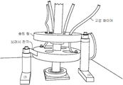
도 1은 본 발명의 바람직한 제1형태에 따른 회전 드럼을 갖춘 코팅 챔버에서 커버 유리를 코팅하기 위한 다수의 척킹 장치의 개략도이다.
도 2는 3-D 커버 유리가 장착된 도 1의 예시의 척킹 장치의 개략 사시도이다.
도 3은 3-D 커버 유리가 장착된 도 2의 예시의 척킹 장치의 부분 분해된 사시도이다.
도 4는 테스트되고 3-D 커버 유리가 장착된 도 1의 예시의 척킹 장치의 개략 입면도이다.
도 5는 도 4의 척킹 장치 일부의 개략 입면도이다.
도 6은 본 발명의 또 다른 예시 형태에 따른 2D 커버 유리의 척킹을 나타내는 척킹 장치의 개략 입면도이다.
도 7은 테스트 리그(test rig)에 장착된 도 4의 척킹 장치의 개략 입면도이다.
도 8은 도 7에 나타낸 테스트 리그 일부의 개략 입면도이다.
도 9는 3-D 커버 유리가 장착된 본 발명에 따른 또 다른 예시의 척킹 장치의 개략 단면도이다.
도 10은 또 다른 테스트 리그에 장착된 테스트되는 도 4의 척킹 장치의 개략 입면도이다.
도 11은 본 발명의 또 다른 형태에 따른, 코팅 동안 회전 구동되는 대형 회전 드럼을 갖춘 코팅 챔버에서 모바일 장치 커버 유리를 코팅하기 위한 예시 방법의 흐름도이다.1 is a schematic view of a plurality of chucking devices for coating a cover glass in a coating chamber with a rotating drum according to a first preferred form of the invention.
Figure 2 is a schematic perspective view of the chucking device of the example of Figure 1 with a 3-D cover glass mounted.
Figure 3 is a partially exploded perspective view of the chucking device of the example of Figure 2 with 3-D cover glass mounted.
Figure 4 is a schematic elevational view of the chucking device of the example of Figure 1 tested and equipped with a 3-D cover glass.
Figure 5 is a schematic elevation view of a portion of the chucking device of Figure 4;
Figure 6 is a schematic elevational view of a chucking apparatus showing chucking of a 2D cover glass according to another exemplary embodiment of the present invention;
Figure 7 is a schematic elevational view of the chucking device of Figure 4 mounted on a test rig.
8 is a schematic elevational view of a portion of the test rig shown in Fig.
9 is a schematic cross-sectional view of another example chucking device according to the present invention with a 3-D cover glass mounted thereon.
Figure 10 is a schematic elevational view of the chucking device of Figure 4 tested in another test rig.
11 is a flowchart of an exemplary method for coating a mobile device cover glass in a coating chamber having a large rotating drum rotationally driven during coating, in accordance with another aspect of the present invention.
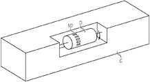
이제 동일한 도면 부호가 여러 도면에 걸쳐 동일한 부분을 나타내는 다양한 도면을 상세하게 참조하면, 도 1은 회전 드럼(D)을 갖춘 코팅 챔버(C)에서 커버 유리를 코팅하기 위한 다수의 척킹 장치(10)를 나타낸다. 후속의 도면들에 나타낸 바와 같이, 상기 척킹 장치(10)는 유입구 및 유출구(22, 24)를 갖춘 U-형상 냉각수 라인(21)을 갖추고 상기 회전 드럼(D)에 제거 가능하게 장착 가능한 거의 직사각형의 액체-냉각 냉각판(20; 이하 간단히 '냉각판'이라고도 칭함)을 포함한다. 통상 PVD 코팅 공정에서 경험되는 것과 같은 높은 주변 온도에 직면하여 냉각판(20)을 냉각시키기 위해 냉각수가 냉각수 라인(21)을 통해 공급될 수 있다. 정전 척(30; ESC)은 상기 냉각판(20)의 상면(26)에 고정되고 회전 드럼(D)의 회전에 의해 야가된 원심력에도 불구하고 커버 유리(G)를 고정시키도록 채용된다.DETAILED DESCRIPTION OF THE PREFERRED EMBODIMENTS Reference will now be made in detail to the various drawings, in which like reference numerals refer to like parts throughout the several views, in which: Figure 1 shows a number of
바람직하게, ESC(30)는 상기 회전 드럼(D)의 회전에 의해 야기된 원심력의 배수인 클램핑력을 생성한다. 보다 바람직하게, 상기 ESC(30)는 상기 회전 드럼(D)의 회전에 의해 야기된 원심력의 적어도 3배인 클램핑력을 생성한다. 옵션으로, 상기 ESC(30)는 인쇄된 폴리이미드를 포함한다.Preferably, the
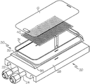
또한, 주변 가스켓(31)은 후면 스퍼터링이 커버 유리(G)의 후면측에 도달하는 것을 방지하기 위해 ESC(30)에 대해 커버 유리(G)의 에지를 밀폐시키도록 ESC(30)의 에지에 인접하여 위치될 수 있다. 옵션으로, ESC(30)는 상기 냉각판(20)에 연결되고 상기 커버 유리(G)의 특정 윤곽과 매칭되도록 형상화될 수 있는 베이스판 또는 맞춤판(35)을 포함한다. 이들 도면에는 에지에 완만한 굴곡을 갖는 커버 유리(G)가 도시되어 있지만, 당업자라면 훨씬 큰 굴곡을 갖거나 또는 전혀 굴곡이 없는 커버 유리(평면 또는 2-D 커버 유리)가 그 커버 유리의 굴곡(또는 그 부재)에 적합한 베이스판을 제공함으로써 코팅될 수 있다는 것을 알 수 있을 것이다. 따라서, 상기 베이스판은 처리되는 특정 커버 유리에 ESC(30)를 맞추기 위한 맞춤기와 같이 작용한다. 상기 베이스판(35)은 내부에 탄성 가스켓(31)을 수용하기 위한 외주 홈(32)을 포함한다. 상기 외주 홈(32)의 깊이는 커버 유리(G)가 드로우(draw)됨에 따라 약간의 "크러쉬(crush)"를 가스켓에 야기하여 커버 유리의 에지 근처에 효과적이면서 단단한 밀폐를 제공하도록 가스켓(31)의 비압축시의 높이보다 약간 작다.The
옵션으로, ESC(30)는 100℃를 초과하는 온도의 진공 챔버(C)에서 사용되고, 반면 액체-냉각 냉각판은 35℃ 이하에서 ESC의 온도를 유지하기 위해 채용된다.Optionally, the
상기 척킹 장치(10)는 3D 커버 유리에 맞는 폴리이미드 ESC(40)를 포함한다. 상기 폴리이미드 ESC(40)는 단지 3D 커버 유리의 평평한 내부 부분과만 접촉한다. 상기 언급한 바와 같이, 상기 ESC에는 반도체 플라즈마-내성 등급의 후면 스퍼터 방지 가스켓(31)이 제공된다.The chucking
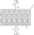
옵션으로, 도 4에 나타낸 바와 같이, 상기 폴리이미드 ESC는 플렉스 회로(flex circuit)를 제조하기 위해 인쇄 회로 기판(PCB) 제조자에 의해 사용될 수 있는 폴리이미드 플렉스 회로 CAD 파일을 위한 PCB 동 레이아웃(50; copper layout)을 포함한다. 그러한 레이아웃 디자인(패턴)은 폴리이미드 필름에 사용하기 위한 상업적으로 이용가능한 디자인이다. 상부 및 하부 리드(51, 52: lead)는 고전압(24 kVdc) 및 고온(250℃) 와이어(55, 56)가 납땜되는 동 패드(53, 54; copper pad)를 갖는다.Optionally, as shown in FIG. 4, the polyimide ESC can be used to produce a
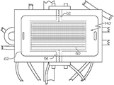
옵션으로, 도 5 내지 7에 나타낸 바와 같이, 커버 유리는 2D 커버 유리(G2)일 수 있다. 예를 들어, 도 6은 폴리이미드 및 기판을 230℃의 오븐에서 최대 35℃로 유지하는 냉각판(20) 상에 2D 커버 유리 기판(G2)을 척킹한 폴리이미드 ESC(140)를 나타낸다. 이러한 2D 클램핑/척킹의 성능을 테스트하기 위해, 기판 표면에 수직인 10G의 원심력을 생성하여, 코닝 5318 IOX 커버 유리 기판을 가진 3개의 이들 ESC(140)를 210 RPM으로 회전시키면서 3시간 동안 클램핑했다. 이러한 원심력은 유리가 ESC 표면에 클램핑되게 하는 유리에서의 분극을 유도하는 정전기장에 의해 반대된다. 따라서, 상기 폴리이미드 ESC(140)는 그와 같은 회전 동안 척킹 장치에 대해 커버 유리를 보다 더 신속하게 유지할 수 있었다.Optionally, as shown in Figures 5-7, the cover glass may be a 2D cover glass G2. For example, FIG. 6 shows a
도 6에서 보는 바와 같이, 폴리이미드 ESC(140)가 커버 유리(G2)의 클리어(clear) 영역에만 클램핑되는 2D 장식 커버 유리가 나타나 있다. 실험에서, 3개의 냉각판이 250℃의 오븐에서 직경이 35cm의 회전 지지부에 장착되고, 예시의 드럼 코터(drum coater)에 대해 산출된 0.64N을 초과하는 1.08N을 야기하는 도 6에 나타낸 12.6g의 커버 유리 샘플과 함께 210 RPM으로 회전되었다. 따라서, 여기에 설명된 폴리이미드 ESC는 드럼 코터 PVD 공정에 적용될 때 최대 20g 커버 유리 크기로 클램핑된 커버 유리를 유지하는 데 필요한 클램핑력을 초과한다. 만약 20g을 초과하는(즉, > 20g) 유리 샘플이 사용되면, 상기 폴리이미드 ESC의 영역을 증가시켜 상기 폴리이미드 ESC(이하 간단히 'ESC'라고도 칭함)에 의해 클램핑되는 유리 영역을 더 확보할 수 있다.As shown in FIG. 6, a 2D decorative cover glass is shown in which the
도 7에 나타낸 바와 같이, 회전 도구 정착물(70)이 ESC를 테스트하는 데 사용되며, 그러한 테스트 정착물(70)은 샤프트의 회전식의 2개의 포트 유니온(도 7의 하부 참조)에서 순환되는 냉각수 및 냉각판을 갖춘 3개의 폴리이미드 2D ESC를 유지한다(3D 테스트 냉각판을 유지할 수도 있다). 도 8은 회전함에 따라 ESC로 대전 전하를 전달하는 250℃ 25kVdc 정격 와이어 및 3.6kVdc 슬립 링 콘택트(slip ring contact)의 확대도이다. 이러한 회전 도구는 250℃의 오븐에 배치되고, 상기 샤프트는 이 샤프트를 210 RPM으로 회전시키는 기어 모터에 외부적으로 연결된다. 이로 인해 회전식 코팅 생성 시스템을 반영한 12.6g의 커버 유리 기판에 0.11N의 원심력이 발생한다. 상기 ESC는 회전 및 가열에도 불구하고 커버 유리를 제 위치에 효과적으로 유지한다.7, a
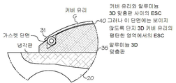
도 9는 냉각판(20)에 고정된 맞춤판(35) 꼭대기의 ESC(40)에 장착된 3D 커버 유리(G)를 나타내는 단면도이다. 상기 맞춤판은 압축 가능한 가스켓(31)을 수용하기 위한 외주 홈을 포함한다. 이러한 도면에 나타낸 특정 실시예에서, 상기 가스켓은 한쪽에 날개를 구비한 벌브-타입(bulb-type)이다. 따라서, 이러한 가스켓의 형태는 3D 커버 유리(G)가 ESC로 압축될 때 넓은 밀폐를 제공하는 슬립(slip) 형태를 갖는다.9 is a sectional view showing a 3D cover glass G mounted on the
도 10은 수행된 실험을 개략적으로 나타내며, 이는 3kVdc가 인가된 폴리이미드 ESC(40)가 거기에 부착된 200g 중량(W)의 Corning 5318 유리 샘플을 클램핑하여 1시간 동안 유지할 수 있다는 것을 입증했다.Figure 10 schematically illustrates the experiment performed, demonstrating that a 3 kVdc applied
또 다른 예시의 형태에서, 본 발명은 직경이 3피트(feet)를 초과하고 100 RPM을 초과하여 회전 구동되는 대형 회전 드럼을 갖춘 코팅 챔버에 의해 실시될 수 있다. 본 발명의 장치는 상기 대형 회전 드럼에 제거 가능하게 장착 가능한 액체-냉각 냉각판 및 상기 액체-냉각 냉각판에 고정되고 100 RPM을 초과하는 상기 대형 회전 드럼의 회전에 의해 야기된 원심력에도 불구하고 커버 유리를 제 위치에 고정시키도록 채용된 정전 척(ESC)을 포함할 수 있다. 상기 정전 척(ESC)은 상기 대형 회전 드럼의 회전에도 불구하고 상기 커버 유리를 제 위치에 확실하게 고정시키기에 충분한 클램핑력을 생성한다.In another exemplary aspect, the invention may be practiced with a coating chamber having a large rotating drum that is rotationally driven in excess of 3 RPM and greater than 3 RPM. The apparatus of the present invention comprises a liquid-cooling cooling plate removably mountable to the large rotating drum and a cover which is fixed to the liquid-cooling cooling plate and which, despite centrifugal forces caused by rotation of the large rotating drum in excess of 100 RPM, And an electrostatic chuck (ESC) employed to fix the glass in place. The electrostatic chuck (ESC) produces a clamping force sufficient to reliably hold the cover glass in position despite the rotation of the large rotating drum.
옵션으로, 회전 드럼을 갖추고 회전 구동되는 진공 코팅 챔버에서 모바일 장치 3D 커버 유리를 코팅하기 위한 척킹 장치가 제공된다. 그러한 예시의 장치는 상기 회전 드럼에 제거 가능하게 장착 가능한 액체-냉각 냉각판을 포함하는 캐리어를 포함한다. 바람직하게, 상기 캐리어는 3D 커버 유리의 3D 프로파일과 매칭시키기 위한 3D 프로파일을 갖는 부분을 포함한다. 또한, 바람직하게, 상기 캐리어는 100 RPM을 초과하는 회전 드럼의 회전에 의해 야기된 원심력에도 불구하고 상기 캐리어의 3D 프로파일에 대해 제 위치에 3D 커버 유리를 고정시키도록 채용된 정전 척(ESC)을 더 포함하며, 상기 정전 척(ESC)은 커버 유리를 제 위치에 확실하게 고정시키기에 충분한 클램핑력을 생성한다.Optionally, a chucking device is provided for coating the mobile device 3D cover glass in a rotationally driven vacuum coating chamber with a rotating drum. An example of such an apparatus includes a carrier including a liquid-cooled cooling plate removably mountable to the rotary drum. Preferably, the carrier comprises a portion having a 3D profile for matching with the 3D profile of the 3D cover glass. Also preferably, the carrier comprises an electrostatic chuck (ESC) adapted to secure the 3D cover glass in position relative to the 3D profile of the carrier despite centrifugal forces caused by rotation of the rotary drum in excess of 100 RPM And the electrostatic chuck (ESC) generates a clamping force sufficient to securely fix the cover glass in place.
바람직하게, 커버 유리는 휴대용 장치를 위한 곡면 커버 유리이고, 상기 척킹 장치는 상기 곡면 커버 유리와 매칭시키도록 상기 ESC와 냉각판간 장착된 곡면 맞춤기를 더 포함한다.Preferably, the cover glass is a curved cover glass for a portable device, and the chucking device further comprises a curved surface mounted between the ESC and the cooling plate to match the curved cover glass.
유리 기판과 ESC간 높은 수준의 접촉 및 평탄성을 촉진시키기 위해, 상기 냉각판은 10 ㎛ 미만의 평탄성 및 1 ㎛ 미만의 표면 거칠기로 기계가공될 수 있다. ESC를 냉각판에 부착하기 위해, ESC가 경화되지 않은 에폭시 위에 놓이고 냉각판이 높은 수준의 평탄성으로 밀링되는 경우, 베이크-아웃(baked-out)된 양면 테이프가 사용되거나 열 에폭시가 사용될 수 있다. 그와 같은 양면 테이프는, 예를 들어 Kapton® 테이프(DuPont의 Kapton® 폴리이미드를 갖는 테이프)일 수 있다. 그러한 양면 테이프는 먼저 접착제에 일반적으로 사용되는 실리콘 오일을 증발시키기 위해 200℃에서 1시간 동안 베이크된다. 이렇게 하면 코팅 공정 중에 오일이 증발하여 냉각판과 커버 유리에 응축되는 것을 방지할 수 있다. 일단 베이크되면, 양면 테이프는 폴리이미드 ESC 후면측에 롤링된 다음 모두가 상기 냉각판에 롤링된다. 3D 파트의 경우, 냉각판 알루미늄 3D 맞춤판 상에 롤링될 것이다. 그러한 ESC의 납땜된 조인트에 대한 기계적 응력을 방지하기 위해, 리드는 전기 아크 경로를 제공하지 않고 ESC를 단락시키도록 유전체로 이루어진 클램핑 메카니즘 사이에 배치된다.In order to promote a high level of contact and flatness between the glass substrate and the ESC, the cold plate can be machined with a flatness of less than 10 [mu] m and a surface roughness of less than 1 [mu] m. In order to attach the ESC to the cold plate, if the ESC is placed over the uncured epoxy and the cold plate is milled to a high level of flatness, baked-out double-sided tape may be used or thermal epoxy may be used. Such double-sided tapes can be, for example, Kapton® tapes (Tapes with Kapton® polyimide from DuPont). Such a double-sided tape is first baked at 200 DEG C for one hour to evaporate the silicone oil commonly used in adhesives. This prevents the oil from evaporating during the coating process and condensing on the cooling plate and cover glass. Once baked, the double-sided tape is rolled on the back side of the polyimide ESC and then all rolled onto the cooling plate. For a 3D part, it will be rolled on a cold plate aluminum 3D fit plate. To prevent mechanical stress on such soldered joints of such ESCs, the leads are disposed between clamping mechanisms made of dielectric material to short the ESC without providing an electrical arc path.
추가의 양면 테이프는 증가된 절연 보호를 제공하기 위해 땜납 조인트 주위에 사용될 수 있다. 상기 ESC가 고진공 플라즈마 환경(1×10⁻⁴ Torr)에서 사용되기 때문에 상기 ESC 또는 양면 테이프 아래에 기포가 포집되지 않는 것이 중요하다. 진공 하에서, 기포가 크게 팽창하여 커버 유리 기판이 상기 ESC로부터 분리되게 한다.Additional double-sided tape can be used around the solder joint to provide increased insulation protection. Since the ESC is used in a high vacuum plasma environment (1 x 10 < -4 > Torr), it is important that no bubbles are trapped under the ESC or double-sided tape. Under vacuum, the bubble expands significantly causing the cover glass substrate to separate from the ESC.
2D 및 3D 커버 유리 ESC/냉각판 어셈블리 모두에서, 가스켓은 후면 스퍼터가 방지되도록 커버 유리 후면측의 에지를 밀폐시키는 데 사용된다. 이들 가스켓은 도 9의 단면에 나타낸 바와 같이 그들 길이를 따라 플립퍼 스트립(flipper strip)을 갖는다. 커버 유리가 ESC의 클램핑력에 의해 가스켓 상에 압축될 때, 플립퍼가 커버 유리의 내측 에지에서 접혀져 그 둘레 주위에 기밀하게 광범위한 밀폐를 형성한다. 그러한 동일한 메카니즘이 평면 2D 커버 유리에 사용된다.In both 2D and 3D cover glass ESC / cold plate assemblies, the gaskets are used to seal the edge on the back side of the cover glass to prevent backside sputtering. These gaskets have a flipper strip along their length as shown in the cross-section of Fig. When the cover glass is compressed on the gasket by the clamping force of the ESC, the flipper is folded at the inner edge of the cover glass to form a tightly airtight seal around its perimeter. Such the same mechanism is used for flat 2D cover glasses.
전력을 공급하기 위해, 극성 스위칭이 없는 12Vdc 내지 3kVdc 고전압 모듈 및 리튬 이온 배터리로 구성되는 3kVdc ESC 전원이 디자인 및 제조된다. 커버 유리 기판에서의 영구적인 분극을 방지하기 위해 고전압 극성 스위칭이 있는 12Vdc 내지 3kVdc 고전압 모듈 및 리튬 이온 배터리로 구성되는 3kVdc ESC 전원이 디자인 및 제조된다. 양 전원 모두는 폴리이미드 ESC의 실험에 사용된다.To supply power, a 3kVdc ESC power supply consisting of a 12Vdc to 3kVdc high-voltage module with no polarity switching and a lithium-ion battery is designed and manufactured. A 3kVdc ESC power supply consisting of a 12Vdc to 3kVdc high voltage module with high voltage polarity switching and a lithium ion battery is designed and manufactured to prevent permanent polarization in the cover glass substrate. Both power sources are used for testing polyimide ESC.
프로토타입에 사용된 전원은 12Vdc를 취하여 최대 3kVdc까지 되는 상업적으로 이용 가능한 고전압 DC-DC 변환기 및 리튬 이온 재충전 가능 배터리로 이루어진다. 또한, 코팅 공정 동안 커버 유리 기판의 영구적인 분극을 방지하기 위해 13분마다 고전압 출력 극성을 스위칭하기 위한 타이머 회로가 통합된 제2전원이 사용된다. 또한, 소정의 고전압 DC 전원이 3.6kVdc인 폴리이미드 ESC에 사용될 수 있다. 각 모듈에 의해 드로우된 전류 및 각 커버 유리에 하나의 ESC가 있는 3개의 ESC 그룹에 파워 모듈을 갖는 180개의 커버 유리 샘플의 통상적인 공정 부하에 공급될 전류는 300mA이고, 180/3=60모듈×300mA=18A이다. 단일의 12Vdc 20A 전원은 모든 180개의 ESC에 전원을 공급할 것이다. 250℃의 공정 온도 및 3.6kVdc의 전기장을 갖는 커버 유리 기판 내의 분자들의 영구적인 분극을 방지하기 위해, 그러한 전기장의 방위를 변경하는 시변의 임의의 파장이 사용될 수 있다. 또한, 상기 ESC에서 고전압의 극성 또한 주기적으로 반전될 수 있음을 알아야 한다.The power source used in the prototype consists of a commercially available high-voltage DC-DC converter with a maximum of 3 kVdc taken at 12 Vdc and a lithium ion rechargeable battery. In addition, a second power supply is used that incorporates a timer circuit to switch the high voltage output polarity every 13 minutes to prevent permanent polarization of the cover glass substrate during the coating process. In addition, a predetermined high-voltage DC power source can be used for polyimide ESC of 3.6 kV dc. The current to be supplied to a typical process load of 180 cover glass samples with power modules in three ESC groups with one ESC in each cover glass and each current drawn by each module is 300mA and 180/3 = 60 modules 300mA = 18A. A single 12Vdc 20A power supply will power all 180 ESCs. Any wavelength of the time-varying wavelength that alters the orientation of such an electric field can be used to prevent permanent polarization of molecules in the cover glass substrate having a process temperature of 250 DEG C and an electric field of 3.6 kVdc. It should also be noted that the polarity of the high voltage in the ESC can also be periodically inverted.
폴리이미드가 열적으로 열화되지 않도록 하고 기판을 냉각시키기 위해, 냉각 판은 23℃와 35℃ 사이를 유지하는 냉각수를 상기 냉각판에 걸쳐 순환시키는 냉각기에 연결된다. 상기 ESC를 230℃ 오븐에서 35℃로 유지하는 실험이 진행되었고 수십 번의 실험 후 폴리이미드의 열화는 보이지 않았다.To prevent the polyimide from thermally degrading and to cool the substrate, the chill plate is connected to a chiller that circulates cooling water through the chill plate, maintaining between 23 캜 and 35 캜. Experiments were conducted to maintain the ESC at 230 DEG C in an oven at 35 DEG C, and no deterioration of the polyimide after several tens of experiments was observed.
유전체, 산화물, 금속 및 반도체 코팅의 PVD 코팅 공정에서 정전기적으로 척킹된 유리를 이용한 실험은 약 50nm의 매우 얇은 코팅 수준 및 약 200nm의 얇은 코팅 수준에서 코팅 균일성 또는 증착 비율에 아무런 영향을 주지 않았다.Experiments with electrostatically chucked glass in PVD coating processes of dielectric, oxide, metal and semiconductor coatings have had no effect on coating uniformity or deposition rate at very thin coating levels of about 50 nm and at thin coating levels of about 200 nm .
커버 유리 기판들을 코팅 진공 챔버 내로 로딩하기 위해, 캐리어 상에 장착된 ESC를 갖춘 상기 캐리어에 전원에 의해 에너지가 공급되어, 상기 커버 유리 기판들이 상기 ESC 상에 배치된다. 전원이 꺼져 ESC로부터 전원이 차단되고 결과적으로 커버 유리 기판이 일시적으로 접착되어 캐리어가 코팅 시스템에서 로딩되거나 언로딩되는 동안 최대 2시간 동안 지속될 수 있다. 일단 회전 드럼에 로딩되면, 상기 ESC는 다시 한번 전원에 연결되고 상기 회전 드럼이 회전되는 동안 커버 유리 샘플들이 이들에 인가된 충분한 클램핑력을 갖게 하는 것을 보장하기 위해 그러한 코팅 공정 동안 상기 ESC에 전원에 의한 에너지 공급이 유지된다.To load the cover glass substrates into the coated vacuum chamber, the carrier with the ESC mounted on the carrier is energized by power, and the cover glass substrates are placed on the ESC. The power can be turned off and the power from the ESC is cut off and consequently the cover glass substrate can be temporarily adhered to last for up to 2 hours while the carrier is being loaded or unloaded in the coating system. Once loaded into the rotary drum, the ESC is once again connected to the power source and is supplied to the ESC during such coating process to ensure that the cover glass samples have sufficient clamping force applied thereto during rotation of the rotary drum. Is maintained.
사용시, 그러한 장비는 상부 폴리이미드 필름과 하부 폴리이미드 필름간 샌드위치된 인터디지털(interdigital) 동 전극들을 갖춘 폴리이미드 필름 스택으로부터 상업적으로 제조된 ESC의 중심에 위치한다. 동 리드들은 도면에 나타낸 바와 같이 생성된다. 그러한 리드들은 절연 유전체로서 작용하는 폴리이미드로 캡슐화된다. 상기 리드들은 ESC를 전원에 연결하기 위해 고전압 고온 와이어가 납땜되는 동 패드에서 종결된다. 상기 리드들이 상기 냉각판의 에지 주위에서 구부러질 때 얇은 동박(copper foil)을 부수지 않고 유연성을 유지하게 하기 위해 물결 형상의 동 트레이스(copper trace)가 상기 리드들에 추가된다. 대안으로, 상기 냉각판에는 상기 리드 근방의 동박에서 날카로운 코너(굴곡)를 피하기 위해 완만한 반경의 에지가 제공될 수 있다.In use, such equipment is located in the center of a commercially manufactured ESC from a polyimide film stack with interdigital copper electrodes sandwiched between an upper polyimide film and a lower polyimide film. These leads are generated as shown in the figure. Such leads are encapsulated in a polyimide that acts as an insulating dielectric. The leads are terminated in a copper pad in which a high voltage hot wire is soldered to connect the ESC to a power source. A wavy copper trace is added to the leads to maintain flexibility without breaking the thin copper foil when the leads are bent around the edge of the cold plate. Alternatively, the cooling plate may be provided with a gentle radius edge to avoid sharp corners (curvature) in the copper foil near the lead.
프로토타입에서, ESC 전극 면적은 10.0cm×5.5cm로 디자인되는 데, 즉 55cm2의 평방 면적을 갖는다. 클램핑력을 테스트하기 위해, Corning 5318 커버 유리의 7.73g 샘플이 10cm×5.5cm로 절단되고, 얇은 와이어 후크(thin wire hook)가 기판의 중심에 고온 접착된다. 상기 냉각판 상의 ESC는 와이어가 매달리도록 거꾸로 클램핑되고 고전압 3kVdc 전원이 상기 ESC에 연결된다. 잠재적으로 유리가 ESC로부터 분리되게 하는 하중을 평가하기 위해 상기 후크 상에 실험실 웨이트(weight)가 매달려 있다. 총 200g이 전극에 매달리고 1시간의 테스트 지속 시간 동안 유지된다. 접착제 및 후크의 중량을 고려(즉, 계수)하지 않고, 유리의 중량에 대한 샘플에 매달린 중량의 비율은 200g/7.73g => 25G 또는 유리 중량의 25.9배에 상당하는 클램핑력이다. 예를 들어, 드럼 코터는 1.5m의 드럼 직경을 가지며 100 RPM으로 회전할 수 있다. 이 때의 그 원주는 4.7m이고 RPS = 100/60 = 1.7 RPS이며, 속도는 v=4.7m/1.7RPS=2.8m/s로 선속도이다. 원심력은 다음과 같다:In the prototype, the ESC electrode area is designed to be 10.0 cm x 5.5 cm, that is, it has a square area of 55 cm 2 . To test the clamping force, a 7.73 g sample of Corning 5318 cover glass is cut to 10 cm x 5.5 cm and a thin wire hook is glued to the center of the substrate at a high temperature. The ESC on the cooling plate is clamped upside down to hang the wire and a high voltage 3kVdc power supply is connected to the ESC. Laboratory weights hang on the hooks to assess the load that potentially causes the glass to separate from the ESC. A total of 200 grams is held on the electrode and maintained for a test duration of 1 hour. The ratio of the weight suspended on the sample to the weight of the glass is the clamping force equivalent to 200 g / 7.73 g = > 25 G or 25.9 times the glass weight, without considering the weight of the adhesive and hooks (i.e. For example, a drum coater has a drum diameter of 1.5 m and can rotate at 100 RPM. The circumference at this time is 4.7 m, RPS = 100/60 = 1.7 RPS, and the velocity is linear velocity at v = 4.7 m / 1.7 RPS = 2.8 m / s. The centrifugal force is as follows:
7.73g 커버 유리의 경우:7.73g For cover glass:
Fc=m(nω/60)2/r=7.73×10-3kg(100*2*π*0.75m/60)2/0.75m=0.64NFc = m (n? / 60) 2 / r = 7.73 10-3 kg (100 * 2 *? * 0.75m / 60) 2 / 0.75m = 0.64N
만약 접촉 면적이 5.5cm×10cm 또는 55cm2이면, 그 면적=0.0055m2이고 이 때 0.64/0.0055m2=115.6N/m2=1.18g/cm2이며, 이는 100 RPM으로 회전하는 1.5m 직경 드럼의 외측에서 부품이 회전될 때 그 부품을 유지하기 위한 최소 결합 강도이다. 상기의 실험에서, 우리는 합쳐진 중량이 207.73g이고, 접촉 면적이 10.0cm×5.5cm 또는 55cm2이라는 것을 알았다. 207.73g/55cm2=3.78g/cm2이고 ESC에 3kVdc 필드가 있다. 상기 나타낸 조건들을 갖는 드럼 코터에 사용하는 데 필요한 클램핑력에 3.87g/cm2/1.18g/cm2=3.3이다.If the contact area is 5.5cm × 10cm or 55cm 2, the area = 0.0055m 2 and this time 0.64 / 0.0055m 2 = 115.6N / m 2 = a 1.18g / cm 2, which 1.5m diameter rotating at 100 RPM It is the minimum bond strength to hold the part as it rotates from the outside of the drum. In the above experiment, we found that the combined weight was 207.73 g and the contact area was 10.0 cm x 5.5 cm or 55 cm 2 . 207.73g / 55cm 2 = 3.78g / cm 2 , and a field 3kVdc the ESC. The clamping force required for use in a drum coater having the above-described conditions is 3.87 g / cm 2 /1.18 g / cm 2 = 3.3.
일반적으로 정전 척킹은 새로운 것은 아니지만, 지금까지 고온을 수반한 플라즈마 진공 코팅에서 커버 유리 기판에 사용되는 것으로 알려지지 않았다. 본 발명은 능동적 냉각에 의해 정전 척의 작동 온도를 부분적으로 완화시킴으로써 정전 척킹을 그와 같은 용도에 사용할 수 있게 한다. 이것은 10G 이상(즉, >10G)의 유지력을 가진 2D 또는 3D 커버 유리 기판의 클램핑을 용이하게 하여, 원심력이 정전 클램핑력에 대항하는 회전 코팅 동작 동안 그러한 커버 유리 기판이 유지될 수 있게 한다. 지금까지, 이것은 업계에서 달성되지 않았다.Generally, electrostatic chucking is not new, but so far it has not been known to be used in cover glass substrates in plasma vacuum coatings with high temperatures. The present invention allows electrostatic chucking to be used for such applications by partially alleviating the operating temperature of the electrostatic chuck by active cooling. This facilitates clamping of a 2D or 3D cover glass substrate with a holding force of 10G or more (i.e., > 10G), such that the centrifugal force allows such cover glass substrate to be retained during rotational coating operations against electrostatic clamping forces. So far, this has not been achieved in the industry.
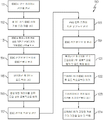
도 11에 나타낸 또 다른 예시의 형태에서, 본 발명은 코팅 동안 회전 구동되는 대형 회전 드럼을 갖춘 코팅 챔버에서 모바일 장치 커버 유리를 코팅하기 위한 방법(110)에 관한 것이다. 상기 방법은 일반적으로 다음의 단계들을 포함한다:11, the present invention is directed to a
상기 커버 유리를 코팅하기 위해 상기 대형 회전 드럼에 상기 커버 유리를 일시적으로 장착하기 위한 다수의 캐리어를 제공하는 단계;Providing a plurality of carriers for temporarily mounting the cover glass on the large rotating drum to coat the cover glass;
상기 캐리어에 정전 척(ESC)을 제공하는 단계;Providing an electrostatic chuck (ESC) to the carrier;
상기 캐리어가 코팅 챔버 외측에 있고 상기 대형 회전 드럼에 장착되지 않은 상태에서 커버 유리를 상기 ESC에 장착하는 단계;Mounting the cover glass to the ESC in a state that the carrier is outside the coating chamber and not mounted to the large rotating drum;
상기 커버 유리를 정전 척 및 캐리어에 일시적으로 고정시키기 위해 상기 ESC를 활성화시키는 단계;Activating the ESC to temporarily secure the cover glass to an electrostatic chuck and a carrier;
상기 ESC가 일시적으로 상기 커버 유리를 고정시키는 동안 캐리어를 상기 대형 회전 드럼에 장착하는 단계;Mounting the carrier on the large rotating drum while the ESC temporarily holds the cover glass;
상기 대형 회전 드럼의 회전에 의해 야기된 원심력에도 불구하고 상기 커버 유리를 상기 캐리어 및 대형 회전 드럼에 단단히 고정하도록 상기 ESC를 활성화시키는 단계;Activating the ESC to securely fix the cover glass to the carrier and the large rotating drum despite centrifugal forces caused by rotation of the large rotating drum;
상기 커버 유리가 상기 캐리어 및 대형 회전 드럼에 단단히 고정된 상태에서 상기 대형 회전 드럼을 회전시키고 상기 커버 유리를 코팅하는 단계;Rotating the large rotating drum and coating the cover glass with the cover glass firmly fixed to the carrier and the large rotating drum;
코팅 및 대형 회전 드럼의 회전을 정지하는 단계;Stopping rotation of the coating and the large rotating drum;
상기 ESC를 비활성화시키는 단계;Deactivating the ESC;
상기 캐리어를 제거하는 단계; 및Removing the carrier; And
상기 커버 유리를 상기 캐리어로부터 제거하는 단계.Removing the cover glass from the carrier.
도 11에 나타낸 바와 같이, 상기 방법(110)은 다음의 단계들을 포함할 수 있다:As shown in Figure 11, the
111: 상기 커버 유리를 코팅하기 위해 상기 대형 회전 드럼에 커버 유리를 일시적으로 장착하기 위한 ESC를 갖춘 다수의 캐리어를 전원에 연결하는 단계;111: connecting a plurality of carriers with an ESC for temporary mounting of the cover glass to the large rotating drum to coat the cover glass;
112: 상기 캐리어가 코팅 챔버 외측에 있고 상기 대형 회전 드럼에 장착되지 않은 상태에서 커버 유리를 상기 ESC에 장착하는 단계;112: mounting the cover glass to the ESC with the carrier outside the coating chamber and not mounted to the large rotating drum;
113: 상기 커버 유리를 정전 척 및 캐리어에 일시적으로 고정시키기 위해 상기 ESC를 활성화시키는 단계;113: activating the ESC to temporarily fix the cover glass to an electrostatic chuck and a carrier;
114: 상기 ESC를 비활성화시키는 단계:114: Deactivating the ESC:
115 및 116: 상기 ESC가 상기 커버 유리를 일시적으로 고정된 상태에서 상기 캐리어를 상기 대형 회전 드럼에 장착하는 단계(상기 캐리어를 로드 락(load lock)에 배치하고 상기 캐리어를 코터 드럼 상에 로봇적으로 배치하는 단계):115 and 116, wherein said ESC mounts said carrier onto said large rotary drum with said cover glass temporarily secured, wherein said carrier is placed in a load lock and said carrier is robotically : ≪ / RTI >
117: 상기 대형 회전 드럼의 회전에 의해 야기된 원심력에도 불구하고 상기 커버 유리를 상기 캐리어 및 대형 회전 드럼에 단단히 고정하도록 상기 ESC를 활성화시키는 단계;117: activating the ESC to securely fix the cover glass to the carrier and the large rotating drum despite centrifugal forces caused by rotation of the large rotating drum;
118: 상기 커버 유리가 상기 캐리어 및 대형 회전 드럼에 단단히 고정된 상태에서 상기 대형 회전 드럼을 회전시키고 상기 커버 유리를 코팅하는 단계, 및 코팅 및 대형 회전 드럼의 회전을 정지하는 단계;118: rotating the large rotating drum and coating the cover glass with the cover glass firmly fixed to the carrier and the large rotating drum, and stopping rotation of the coating and the large rotating drum;
119: 상기 ESC를 비활성화시키는 단계;119: deactivating the ESC;
121-122: 상기 대형 회전 드럼 및 로드 락으로부터 캐리어를 제거하는 단계;121-122: removing the carrier from the large rotating drum and the load lock;
123: 상기 커버 유리를 캐리어로부터 제거하는 단계; 및123: removing the cover glass from the carrier; And
124: 상기 커버 유리를 검사 및 팩킹(packing)하는 단계.124: Inspecting and packing the cover glass.
옵션으로, 상기 ESC는 상기 회전 드럼의 회전에 의해 야기된 원심력의 배수인 클램핑력을 생성한다. 보다 바람직하게, 상기 ESC는 상기 회전 드럼의 회전에 의해 야기된 원심력의 적어도 3배인 클램핑력을 생성한다.Optionally, the ESC produces a clamping force that is a multiple of the centrifugal force caused by the rotation of the rotary drum. More preferably, the ESC produces a clamping force that is at least three times the centrifugal force caused by the rotation of the rotary drum.
이러한 방법은 휴대용 장치를 위한 2D 커버 유리 또는 곡면(3D) 커버 유리에 사용될 수 있다. 곡면(3D) 커버 유리의 경우, 캐리어는 상기 기술한 바와 같이 상기 곡면 커버 유리의 굴곡과 매칭시키기 위한 곡면 맞춤기를 더 포함할 수 있다.This method can be used for 2D cover glass or curved (3D) cover glass for portable devices. In the case of a curved (3D) cover glass, the carrier may further comprise a curved surface for matching the curvature of the curved cover glass as described above.
그와 같은 코팅 방법은 커버 유리에 긁힘 방지 코팅을 제공하기 위해 ESC에 사용될 수 있다. 더욱이, 상기 코팅 방법은 옵션으로 100℃를 초과하는 온도의 진공 코팅 챔버에 사용될 수 있고, 상기 방법은 35℃ 이하와 같은 상대적으로 낮은 작업 온도에서 ESC의 온도를 유지하기 위해 캐리어에 액체-냉각 냉각판을 제공하는 단계를 더 포함할 수 있다.Such a coating method can be used for ESC to provide a scratch-resistant coating on the cover glass. Moreover, the coating method may optionally be used in a vacuum coating chamber at a temperature in excess of < RTI ID = 0.0 > 100 C < / RTI & And providing a plate.
또 다른 예시의 형태에서, 본 발명은 코팅이 제공될 때 커버 유리가 회전 드럼 상에 일시적으로 장착되는 스퍼터링 플라즈마 공정을 통해 코팅이 적용되는 코팅을 갖는 모바일 장치 커버 유리를 코팅하기 위한 개선된 제조 방법에 관한 것이다. 상기 개선된 제조 방법은 상기 회전 드럼의 회전에 의해 야기된 커버 유리에 작용하는 원심력에도 불구하고 커버 유리를 제 위치에 유지하기에 충분한 클램핑력으로 회전 드럼에 일시적으로 고정된 캐리어에 ESC에 의해 커버 유리를 정전기적으로 클램핑하는 단계를 포함하며, 상기 커버 유리를 정전기적으로 클램핑하지 않을 경우, 상기 회전 드럼이 회전될 때 상기 커버 유리가 회전 드럼으로부터 벗어나는 경향이 있다.In another exemplary aspect, the present invention provides an improved method for coating a mobile device cover glass having a coating to which a coating is applied through a sputtering plasma process in which a cover glass is temporarily mounted on a rotating drum when the coating is provided . The improved manufacturing method is characterized in that the carrier is temporarily fixed to the rotary drum with a clamping force sufficient to keep the cover glass in position despite the centrifugal force acting on the cover glass caused by rotation of the rotary drum, Electrostatically clamping the glass, and when the cover glass is not electrostatically clamped, the cover glass tends to escape from the rotating drum when the rotating drum is rotated.
몇가지 이점Some benefits
코터에서 커버 유리 기판의 정전 척킹은 세정의 후 처리 공정을 필요로 하는 처리된 커버 유리 상에 어떠한 잔류물도 남기지 않는 세정 기술이다. 그러한 코터에서 커버 유리 기판의 정전 척킹은 매우 낮은 노동 시간(현재 테이핑 공정의 10분과 비교된 초)을 가지므로 코팅 챔버로의 신속한 로딩 및 언로딩이 가능하다. 수냉은 폴리이미드 및 커버 유리 기판을 실온에 가깝게 유지하므로, 폴리이미드 ESC는 긴 수명과 다수 사용 사이클을 가지며 커버 유리 기판의 점증적인 공정 온도 상승으로 노후화되지 않는다.Electrostatic chucking of a cover glass substrate in a coater is a cleaning technique that leaves no residue on the treated cover glass requiring a post-treatment of the cleaning. The electrostatic chucking of the cover glass substrate in such a coater has a very low working time (seconds compared to 10 minutes of the current taping process), allowing rapid loading and unloading into the coating chamber. Since water cooling keeps the polyimide and cover glass substrates close to room temperature, the polyimide ESC has a long lifetime and many cycles of use and is not aged due to the incremental process temperature rise of the cover glass substrate.
그러한 폴리이미드 ESC는 포토 패터닝 방법에 의한 다양한 인쇄 회로 기판 제조 하우스에 의해 용이하게 제조되며, 상업적으로 디자인되고 제조된 ESC($1,000)와 비교하여 매우 저렴한 비용($10 내지 $100)이고, 상업적으로 디자인된 ESC는 배송에 몇 개월이 걸리지만, 폴리이미드 ESC의 배송 시간은 몇 일(5일)이다. 상기 폴리이미드 ESC는 얇은(0.13mm) 필름으로 이루어지고 유연하며, 특정 윤곽으로 형상화된 표면에 적용될 수 있어, 3D 커버 유리 기판을 위한 이상적인 클램핑 메카니즘이다.Such polyimide ESCs are easily fabricated by a variety of printed circuit board manufacturing houses by photopatterning methods and are very low cost ($ 10 to $ 100) compared to commercially designed and manufactured ESC ($ 1,000) ESC takes several months to deliver, but Polyimide ESC has a delivery time of a few days (5 days). The polyimide ESC is an ideal clamping mechanism for a 3D cover glass substrate, which is made of a thin (0.13 mm) film and is flexible and can be applied to a surface shaped to a specific contour.
본 발명은 높은 수준의 코팅 균일성을 유지하도록 유리 플라즈마 코팅 공정에 사용하기 위해 커버 유리 기판을 제 위치에 정확히 위치 및 유지시키는 방법 및 장치를 제공하는 한편, 바람직하지 않은 잔류물 또는 손상 없이 처리된 기판을 로딩 및 언로딩하기 위한 간단하고 효율적인 수단을 제공한다.The present invention provides a method and apparatus for accurately positioning and maintaining a cover glass substrate in position for use in a glass plasma coating process to maintain a high level of coating uniformity, Providing a simple and efficient means for loading and unloading the substrate.
본원에 기술된 휴대용 디스플레이 유리 정전 척킹 방법 및 장치는 기존의 플라즈마 박막 증착 시스템의 간단한 개보수를 가능하게 함으로써 저비용 처리 능력을 제공하지만, 통상적으로 그 내부에서 경험되는 고온에 의한 악영향을 받지 않는다.The portable display glass electrostatic chucking method and apparatus described herein provide a low cost processing capability by allowing simple refinement of existing plasma film deposition systems, but are not typically adversely affected by the high temperatures experienced therein.
본 발명이 바람직한 예시의 실시예들과 관련하여 설명되었지만, 당업자는 부가된 청구범위에서 정의된 본 발명의 사상 및 범주를 벗어나지 않고 다양한 변경, 추가, 삭제 및 수정이 이루어질 수 있음을 이해할 수 있을 것이다. 몇몇 예시의 실시예는 다음을 포함한다.While the invention has been described in conjunction with the preferred exemplary embodiments, it will be understood by those skilled in the art that various changes, additions, deletions, and modifications may be made without departing from the spirit and scope of the invention as defined in the appended claims . Some exemplary embodiments include the following.
실시예 1. 회전 드럼을 갖추고 회전 구동되는 진공 코팅 챔버에서 모바일 장치 3D 커버 유리를 코팅하기 위한 척킹 장치로서, 상기 척킹 장치는:A chucking apparatus for coating a mobile device 3D cover glass in a vacuum-driven vacuum coating chamber equipped with a rotary drum, said chucking apparatus comprising:
상기 상기 회전 드럼에 제거 가능하게 장착 가능한 액체-냉각 냉각판을 포함하는 캐리어를 포함하며,And a carrier including a liquid-cooled cooling plate removably mountable to said rotary drum,
상기 캐리어는 3D 커버 유리의 3D 프로파일과 매칭되는 3D 프로파일을 갖는 부분을 포함하고;The carrier comprising a portion having a 3D profile that matches the 3D profile of the 3D cover glass;
상기 캐리어는 100 RPM을 초과하는 상기 회전 드럼의 회전에 의해 야기된 원심력에도 불구하고 3D 커버 유리를 캐리어의 3D 프로파일에 대해 제 위치에 고정시키도록 채용된 정전 척(ESC)을 더 포함하며, 상기 ESC는 상기 3D 커버 유리를 제 위치에 확실하게 고정시키기에 충분한 클램핑력을 생성한다.The carrier further comprises an electrostatic chuck (ESC) employed to lock the 3D cover glass in position relative to the 3D profile of the carrier despite centrifugal forces caused by rotation of the rotary drum in excess of 100 RPM, The ESC creates a clamping force sufficient to reliably secure the 3D cover glass in place.
실시예 2. 회전 드럼을 갖춘 코팅 챔버에서 커버 유리를 코팅하기 위한 척킹 장치로서, 상기 척킹 장치는:Example 2 A chucking apparatus for coating a cover glass in a coating chamber with a rotating drum, said chucking apparatus comprising:
상기 회전 드럼에 제거 가능하게 장착 가능한 액체-냉각 냉각판; 및A liquid-cooling cooling plate removably mountable to the rotary drum; And
상기 액체-냉각 냉각판에 고정되고 상기 회전 드럼의 회전에 의해 야기된 원심력에도 불구하고 상기 커버 유리를 제 위치에 고정시키도록 채용된 정전 척(ESC)을 포함한다.And an electrostatic chuck (ESC) fixed to the liquid-cooling chill plate and adapted to fix the cover glass in place despite centrifugal forces caused by rotation of the rotary drum.
실시예 3. 실시예 1 또는 실시예 2에서와 같은 척킹 장치에 있어서, ESC는 상기 회전 드럼의 회전에 의해 야기된 원심력의 배수인 클램핑력을 생성한다.Embodiment 3. In the chucking apparatus as in Embodiment 1 or Embodiment 2, the ESC produces a clamping force which is a multiple of the centrifugal force caused by the rotation of the rotary drum.
실시예 4. 실시예 1 또는 실시예 2에서와 같은 척킹 장치에 있어서, 상기 ESC는 상기 회전 드럼에 의해 야기된 원심력의 적어도 3배인 클램핑력을 생성한다.Embodiment 4 In the chucking apparatus as in Embodiment 1 or Embodiment 2, the ESC produces a clamping force that is at least three times the centrifugal force caused by the rotary drum.
실시예 5. 선행하는 실시예들 중 어느 한 실시예에서와 같은 척킹 장치에 있어서, 상기 커버 유리는 휴대용 장치를 위한 곡면 커버 유리이고, 상기 척킹 장치는 상기 곡면 커버 유리의 굴곡과 매칭시키도록 ESC와 액체-냉각 냉각판간 장착된 곡면 맞춤기를 더 포함한다.5. A chucking device as in any one of the preceding embodiments, wherein said cover glass is a curved cover glass for a portable device, said chucking device comprising an ESC to match the curvature of said curved cover glass, And a liquid-cooling cooling plate-mounted curved surface aligner.
실시예 6. 선행하는 실시예들 중 어느 한 실시예에서와 같은 척킹 장치에 있어서, 상기 ESC는 인쇄된 폴리이미드를 포함한다.Embodiment 6 In a chucking apparatus as in any one of the preceding embodiments, the ESC comprises a printed polyimide.
실시예 7. 선행하는 실시예들 중 어느 한 실시예에서와 같은 척킹 장치에 있어서, 후면 스퍼터링이 커버 유리의 후면측에 도달하는 것을 방지하기 위해 ESC에 대해 커버 유리의 에지를 밀폐시키도록 ESC에 인접하여 위치된 주변 가스켓을 더 포함한다.Embodiment 7: In a chucking apparatus as in any of the preceding embodiments, an ESC is used to seal the edge of the cover glass relative to the ESC to prevent backside sputtering from reaching the back side of the cover glass. And further includes an adjacent gasket positioned adjacent thereto.
실시예 8. 선행하는 실시예들 중 어느 한 실시예에서와 같은 척킹 장치에 있어서, ESC는 커버 유리에 긁힘 방지 코팅을 제공하기 위해 사용된다.Embodiment 8. In a chucking apparatus as in any one of the preceding embodiments, the ESC is used to provide an anti-scratch coating to the cover glass.
실시예 9. 선행하는 실시예들 중 어느 한 실시예에서와 같은 척킹 장치에 있어서, ESC는 100℃를 초과하는 온도의 진공 챔버에서 사용된다.Embodiment 9. In a chucking apparatus as in any of the preceding embodiments, the ESC is used in a vacuum chamber at a temperature in excess of < RTI ID = 0.0 > 100 C. < / RTI >
실시예 10. 실시예 9에서와 같은 척킹 장치에 있어서, 액체-냉각 냉각판은 35℃ 이하에서 ESC의 온도를 유지하기 위해 채용된다.Example 10. In the chucking apparatus as in Example 9, the liquid-cooled cold plate was employed to maintain the temperature of the ESC below 35 占 폚.
실시예 11. 직경이 3피트(feet)를 초과하고 100 RPM을 초과하여 회전 구동되는 대형 회전 드럼을 갖춘 코팅 챔버에서 모바일 장치 커버 유리를 코팅하기 위한 척킹 장치로서, 상기 척킹 장치는:A chucking apparatus for coating a mobile device cover glass in a coating chamber having a large rotating drum with a diameter greater than 3 feet and rotationally driven in excess of 100 RPM,
상기 대형 회전 드럼에 제거 가능하게 장착 가능한 액체-냉각 냉각판; 및A liquid-cooling cooling plate removably mountable to the large rotating drum; And
상기 액체-냉각 냉각판에 고정되고 100 RPM을 초과하는 상기 대형 회전 드럼의 회전에 의해 야기된 원심력에도 불구하고 상기 커버 유리를 제 위치에 고정시키도록 채용된 정전 척(ESC)을 포함하며,An electrostatic chuck (ESC) secured to the liquid-cooled cooling plate and adapted to fix the cover glass in place despite centrifugal forces caused by rotation of the large rotating drum in excess of 100 RPM,
상기 정전 척(ESC)은 상기 커버 유리를 제 위치에 확실하게 고정시키기에 충분한 클램핑력을 생성한다.The electrostatic chuck (ESC) produces a clamping force sufficient to securely secure the cover glass in place.
실시예 12. 코팅 동안 회전 구동되는 대형 회전 드럼을 갖춘 코팅 챔버에서 모바일 장치 커버 유리를 코팅하기 위한 방법으로서, 상기 코팅 방법은:12. A method for coating a mobile device cover glass in a coating chamber having a large rotating drum rotationally driven during coating, said coating method comprising:
a. 상기 커버 유리를 코팅하기 위해 상기 대형 회전 드럼에 상기 커버 유리를 일시적으로 장착하기 위한 다수의 캐리어를 제공하는 단계;a. Providing a plurality of carriers for temporarily mounting the cover glass on the large rotating drum to coat the cover glass;
b. 상기 캐리어에 정전 척(ESC)을 제공하는 단계;b. Providing an electrostatic chuck (ESC) to the carrier;
c. 상기 캐리어가 코팅 챔버 외측에 있고 상기 대형 회전 드럼에 장착되지 않은 상태에서 커버 유리를 상기 ESC에 장착하는 단계;c. Mounting the cover glass to the ESC in a state that the carrier is outside the coating chamber and not mounted to the large rotating drum;
d. 상기 커버 유리를 정전 척 및 캐리어에 일시적으로 고정시키기 위해 상기 ESC를 활성화시키는 단계;d. Activating the ESC to temporarily secure the cover glass to an electrostatic chuck and a carrier;
e. 상기 ESC가 일시적으로 상기 커버 유리를 고정시키는 동안 캐리어를 상기 대형 회전 드럼에 장착하는 단계;e. Mounting the carrier on the large rotating drum while the ESC temporarily holds the cover glass;
f. 상기 대형 회전 드럼의 회전에 의해 야기된 원심력에도 불구하고 상기 커버 유리를 상기 캐리어 및 대형 회전 드럼에 단단히 고정하도록 상기 ESC를 활성화시키는 단계;f. Activating the ESC to securely fix the cover glass to the carrier and the large rotating drum despite centrifugal forces caused by rotation of the large rotating drum;
g. 상기 커버 유리가 상기 캐리어 및 대형 회전 드럼에 단단히 고정된 상태에서 상기 대형 회전 드럼을 회전시키고 상기 커버 유리를 코팅하는 단계;g. Rotating the large rotating drum and coating the cover glass with the cover glass firmly fixed to the carrier and the large rotating drum;
h. 코팅 및 대형 회전 드럼의 회전을 정지하는 단계;h. Stopping rotation of the coating and the large rotating drum;
i. 상기 ESC를 비활성화시키는 단계;i. Deactivating the ESC;
j. 상기 캐리어를 제거하는 단계; 및j. Removing the carrier; And
k. 상기 커버 유리를 상기 캐리어로부터 제거하는 단계를 포함한다.k. And removing the cover glass from the carrier.
실시예 13. 실시예 12에서와 같은 코팅 방법에 있어서, 상기 ESC는 상기 대형 회전 드럼의 회전에 의해 야기된 원심력의 배수인 클램핑력을 생성한다.13. The coating method as in embodiment 12 wherein the ESC produces a clamping force that is a multiple of the centrifugal force caused by rotation of the large rotating drum.
실시예 14. 실시예 12 또는 실시예 13에서와 같은 코팅 방법에 있어서, 상기 ESC는 상기 대형 회전 드럼의 회전에 의해 야기된 원심력의 적어도 3배인 클램핑력을 생성한다.14. The coating method as in embodiment 12 or 13, wherein said ESC produces a clamping force that is at least three times the centrifugal force caused by rotation of said large rotating drum.
실시예 15. 실시예 12-14 중 어느 한 실시예에서와 같은 코팅 방법에 있어서, 상기 커버 유리는 휴대용 장치를 위한 곡면 커버 유리이고, 상기 캐리어는 상기 곡면 커버 유리의 굴곡과 매칭시키기 위한 곡면 맞춤기를 더 포함한다.15. The coating method as in any one of embodiments 12-14, wherein said cover glass is a curved cover glass for a portable device, said carrier having a curved surface for matching with curvature of said curved cover glass .
실시예 16. 실시예 12-15 중 어느 한 실시예에서와 같은 코팅 방법에 있어서, 상기 ESC는 인쇄된 폴리이미드를 포함한다.16. The coating method as in any one of embodiments 12-15, wherein the ESC comprises a printed polyimide.
실시예 17. 실시예 12-16 중 어느 한 실시예에서와 같은 코팅 방법에 있어서, 캐리어는 후면 스퍼터링이 커버 유리의 후면측에 도달하는 것을 방지하기 위해 ESC에 대해 커버 유리의 에지를 밀폐시키도록 ESC에 인접하여 위치된 주변 가스켓을 포함한다.17. A coating method as in any one of embodiments 12-16, wherein the carrier is configured to seal the edges of the cover glass against ESC to prevent backside sputtering from reaching the back side of the cover glass. Lt; RTI ID = 0.0 > ESC. ≪ / RTI >
실시예 18. 실시예 12-17 중 어느 한 실시예에서와 같은 코팅 방법에 있어서, ECS는 커버 유리에 긁힘 방지 코팅을 제공하기 위해 사용된다.Example 18. In the same coating method as in any of Examples 12-17, ECS is used to provide a scratch-resistant coating on the cover glass.
실시예 19. 실시예 12-18 중 어느 한 실시예에서와 같은 코팅 방법에 있어서, ESC는 100℃를 초과하는 온도의 진공 코팅 챔버에 사용되고, 상기 방법은 35℃ 이하에서 ESC의 온도를 유지하기 위해 캐리어에 액체-냉각 냉각판을 제공하는 단계를 더 포함한다.Example 19. In the same coating method as in any one of Examples 12-18, the ESC is used in a vacuum coating chamber at a temperature in excess of 100 DEG C, and the method maintains the temperature of the ESC below 35 DEG C And providing the liquid-cooled cooling plate to the carrier.
실시예 20. 코팅이 제공될 때 커버 유리가 회전 드럼 상에 일시적으로 장착되는 스퍼터링 플라즈마 공정을 통해 코팅이 적용되는 코팅을 갖는 모바일 장치 커버 유리를 코팅하기 위한 개선된 제조 방법으로서, 상기 개선된 제조 방법은:
상기 회전 드럼의 회전에 의해 야기된 커버 유리에 작용하는 원심력에도 불구하고 커버 유리를 제 위치에 유지하기에 충분한 클램핑력으로 회전 드럼에 일시적으로 고정된 캐리어에 ESC에 의해 커버 유리를 정전기적으로 클램핑하는 단계를 포함하며,The cover glass is electrostatically clamped by the ESC to a carrier which is temporarily fixed to the rotary drum with a clamping force sufficient to keep the cover glass in place despite the centrifugal force acting on the cover glass caused by the rotation of the rotary drum , ≪ / RTI >
상기 커버 유리를 정전기적으로 클램핑하지 않을 경우, 상기 회전 드럼이 회전될때 상기 커버 유리가 회전 드럼으로부터 벗어나는 경향이 있다.When the cover glass is not electrostatically clamped, the cover glass tends to escape from the rotary drum when the rotary drum is rotated.
실시예 21. 실시예 20에서와 같은 방법에 있어서, 상기 ESC는 상기 회전 드럼의 회전에 의해 야기된 원심력의 배수인 클램핑력을 생성한다.21. The method of
Claims (21)
상기 상기 회전 드럼에 제거 가능하게 장착 가능한 액체-냉각 냉각판을 포함하는 캐리어를 포함하며,
상기 캐리어는 3D 커버 유리의 3D 프로파일과 매칭되는 3D 프로파일을 갖는 부분을 포함하고;
상기 캐리어는 100 RPM을 초과하는 상기 회전 드럼의 회전에 의해 야기된 원심력에도 불구하고 3D 커버 유리를 캐리어의 3D 프로파일에 대해 제 위치에 고정시키도록 채용된 정전 척(ESC)을 더 포함하며, 상기 ESC는 상기 3D 커버 유리를 제 위치에 확실하게 고정시키기에 충분한 클램핑력을 생성하는, 척킹 장치.CLAIMS 1. A chucking apparatus for coating a mobile device 3D cover glass in a rotationally driven vacuum coating chamber with a rotating drum, said chucking apparatus comprising:
And a carrier including a liquid-cooled cooling plate removably mountable to said rotary drum,
The carrier comprising a portion having a 3D profile that matches the 3D profile of the 3D cover glass;
The carrier further comprises an electrostatic chuck (ESC) employed to lock the 3D cover glass in position relative to the 3D profile of the carrier despite centrifugal forces caused by rotation of the rotary drum in excess of 100 RPM, ESC produces a clamping force sufficient to reliably secure the 3D cover glass in place.
상기 회전 드럼에 제거 가능하게 장착 가능한 액체-냉각 냉각판; 및
상기 액체-냉각 냉각판에 고정되고 상기 회전 드럼의 회전에 의해 야기된 원심력에도 불구하고 상기 커버 유리를 제 위치에 고정시키도록 채용된 정전 척(ESC)을 포함하는, 척킹 장치.A chucking apparatus for coating a cover glass in a coating chamber equipped with a rotating drum, said chucking apparatus comprising:
A liquid-cooling cooling plate removably mountable to the rotary drum; And
And an electrostatic chuck (ESC) secured to the liquid-cooling chill plate and adapted to secure the cover glass in position despite centrifugal forces caused by rotation of the rotary drum.
ESC는 회전 드럼의 회전에 의해 야기된 원심력의 배수인 클램핑력을 생성하는, 척킹 장치.The method according to claim 1 or 2,
ESC produces a clamping force which is a multiple of the centrifugal force caused by rotation of the rotating drum.
ESC는 회전 드럼에 의해 야기된 원심력의 적어도 3배인 클램핑력을 생성하는, 척킹 장치.The method according to claim 1 or 2,
ESC produces a clamping force that is at least three times the centrifugal force caused by the rotating drum.
커버 유리는 휴대용 장치를 위한 곡면 커버 유리이고, 상기 척킹 장치는 상기 곡면 커버 유리의 굴곡과 매칭시키도록 ESC와 액체-냉각 냉각판간 장착된 곡면 맞춤기를 더 포함하는, 척킹 장치.The method of claim 2,
Wherein the cover glass is a curved cover glass for a portable device and wherein the chucking device further comprises a curved surface mounted between the ESC and the liquid-cooled cooling plate to match the curvature of the curved cover glass.
ESC는 인쇄된 폴리이미드를 포함하는, 척킹 장치.The method according to claim 1 or 2,
Wherein the ESC comprises printed polyimide.
후면 스퍼터링이 커버 유리의 후면측에 도달하는 것을 방지하기 위해 ESC에 대해 커버 유리의 에지를 밀폐시키도록 ESC에 인접하여 위치된 주변 가스켓을 더 포함하는, 척킹 장치.The method according to claim 1 or 2,
Further comprising a peripheral gasket positioned adjacent the ESC to seal the edge of the cover glass relative to the ESC to prevent back sputtering from reaching the back side of the cover glass.
ESC는 커버 유리에 긁힘 방지 코팅을 제공하기 위해 사용되는, 척킹 장치.The method according to claim 1 or 2,
ESC is used to provide an anti-scratch coating on the cover glass.
ESC는 100℃를 초과하는 온도의 진공 챔버에서 사용되는, 척킹 장치.The method according to claim 1 or 2,
ESC is used in a vacuum chamber at a temperature in excess of < RTI ID = 0.0 > 100 C. < / RTI >
액체-냉각 냉각판은 35℃ 이하에서 ESC의 온도를 유지하기 위해 채용되는, 척킹 장치.The method of claim 9,
Wherein the liquid-cooled chill plate is employed to maintain the temperature of the ESC below < RTI ID = 0.0 > 35 C. < / RTI >
상기 대형 회전 드럼에 제거 가능하게 장착 가능한 액체-냉각 냉각판; 및
상기 액체-냉각 냉각판에 고정되고 100 RPM을 초과하는 상기 대형 회전 드럼의 회전에 의해 야기된 원심력에도 불구하고 상기 커버 유리를 제 위치에 고정시키도록 채용된 정전 척(ESC)을 포함하며,
상기 정전 척(ESC)은 상기 커버 유리를 제 위치에 확실하게 고정시키기에 충분한 클램핑력을 생성하는, 척킹 장치.CLAIMS 1. A chucking apparatus for coating a mobile device cover glass in a coating chamber having a large rotating drum with a diameter greater than 3 feet and rotationally driven in excess of 100 RPM,
A liquid-cooling cooling plate removably mountable to the large rotating drum; And
An electrostatic chuck (ESC) secured to the liquid-cooled cooling plate and adapted to fix the cover glass in place despite centrifugal forces caused by rotation of the large rotating drum in excess of 100 RPM,
Wherein said electrostatic chuck (ESC) produces a clamping force sufficient to securely secure said cover glass in place.
a. 상기 커버 유리를 코팅하기 위해 상기 대형 회전 드럼에 상기 커버 유리를 일시적으로 장착하기 위한 다수의 캐리어를 제공하는 단계;
b. 상기 캐리어에 정전 척(ESC)을 제공하는 단계;
c. 상기 캐리어가 코팅 챔버 외측에 있고 상기 대형 회전 드럼에 장착되지 않은 상태에서 커버 유리를 상기 ESC에 장착하는 단계;
d. 상기 커버 유리를 정전 척 및 캐리어에 일시적으로 고정시키기 위해 상기 ESC를 활성화시키는 단계;
e. 상기 ESC가 일시적으로 상기 커버 유리를 고정시키는 동안 캐리어를 상기 대형 회전 드럼에 장착하는 단계;
f. 상기 대형 회전 드럼의 회전에 의해 야기된 원심력에도 불구하고 상기 커버 유리를 상기 캐리어 및 대형 회전 드럼에 단단히 고정하도록 상기 ESC를 활성화시키는 단계;
g. 상기 커버 유리가 상기 캐리어 및 대형 회전 드럼에 단단히 고정된 상태에서 상기 대형 회전 드럼을 회전시키고 상기 커버 유리를 코팅하는 단계;
h. 코팅 및 대형 회전 드럼의 회전을 정지하는 단계;
i. 상기 ESC를 비활성화시키는 단계;
j. 상기 캐리어를 제거하는 단계; 및
k. 상기 커버 유리를 상기 캐리어로부터 제거하는 단계를 포함하는, 코팅 방법.A method for coating a mobile device cover glass in a coating chamber having a large rotating drum rotationally driven during coating, the coating method comprising:
a. Providing a plurality of carriers for temporarily mounting the cover glass on the large rotating drum to coat the cover glass;
b. Providing an electrostatic chuck (ESC) to the carrier;
c. Mounting the cover glass to the ESC in a state that the carrier is outside the coating chamber and not mounted to the large rotating drum;
d. Activating the ESC to temporarily secure the cover glass to an electrostatic chuck and a carrier;
e. Mounting the carrier on the large rotating drum while the ESC temporarily holds the cover glass;
f. Activating the ESC to securely fix the cover glass to the carrier and the large rotating drum despite centrifugal forces caused by rotation of the large rotating drum;
g. Rotating the large rotating drum and coating the cover glass with the cover glass firmly fixed to the carrier and the large rotating drum;
h. Stopping rotation of the coating and the large rotating drum;
i. Deactivating the ESC;
j. Removing the carrier; And
k. And removing the cover glass from the carrier.
상기 ESC는 상기 대형 회전 드럼의 회전에 의해 야기된 원심력의 배수인 클램핑력을 생성하는, 코팅 방법.The method of claim 12,
Wherein said ESC produces a clamping force that is a multiple of centrifugal force caused by rotation of said large rotating drum.
상기 ESC는 상기 대형 회전 드럼의 회전에 의해 야기된 원심력의 적어도 3배인 클램핑력을 생성하는, 코팅 방법.The method of claim 12,
Wherein said ESC produces a clamping force that is at least three times the centrifugal force caused by rotation of said large rotating drum.
상기 커버 유리는 휴대용 장치를 위한 곡면 커버 유리이고, 상기 캐리어는 상기 곡면 커버 유리의 굴곡과 매칭시키기 위한 곡면 맞춤기를 더 포함하는, 코팅 방법.The method of claim 12,
Wherein the cover glass is a curved cover glass for a portable device, the carrier further comprising a curved surface for matching the curvature of the curved cover glass.
ESC는 인쇄된 폴리이미드를 포함하는, 코팅 방법.The method according to any one of claims 12 to 15,
Wherein the ESC comprises a printed polyimide.
후면 스퍼터링이 커버 유리의 후면측에 도달하는 것을 방지하기 위해 ESC에 대해 커버 유리의 에지를 밀폐시키도록 ESC에 인접하여 위치된 주변 가스켓을 포함하는, 코팅 방법.The method according to one of claims 12 to 15,
And a peripheral gasket positioned adjacent the ESC to seal the edge of the cover glass relative to the ESC to prevent rear sputtering from reaching the back side of the cover glass.
ESC는 커버 유리에 긁힘 방지 코팅을 제공하기 위해 사용되는, 코팅 방법.The method according to any one of claims 12 to 15,
ESC is used to provide a scratch-resistant coating on the cover glass.
ESC는 100℃를 초과하는 온도의 진공 코팅 챔버에 사용되고, 상기 코팅 방법은 35℃ 이하에서 ESC의 온도를 유지하기 위해 캐리어를 액체-냉각 냉각판에 제공하는 단계를 더 포함하는, 코팅 방법.The method according to any one of claims 12 to 15,
The ESC is used in a vacuum coating chamber at a temperature in excess of 100 DEG C and the coating method further comprises providing a carrier to the liquid-cooled cooling plate to maintain the temperature of the ESC at 35 DEG C or less.
상기 회전 드럼의 회전에 의해 야기된 커버 유리에 작용하는 원심력에도 불구하고 커버 유리를 제 위치에 유지하기에 충분한 클램핑력으로 회전 드럼에 일시적으로 고정된 캐리어에 ESC에 의해 커버 유리를 정전기적으로 클램핑하는 단계를 포함하며,
상기 커버 유리를 정전기적으로 클램핑하지 않을 경우, 상기 회전 드럼이 회전될때 상기 커버 유리가 회전 드럼으로부터 벗어나는, 개선된 제조 방법.An improved manufacturing method for coating a mobile device cover glass having a coating to which a coating is applied through a sputtering plasma process wherein the cover glass is temporarily mounted on a rotating drum when a coating is provided, said improved manufacturing method comprising:
The cover glass is electrostatically clamped by the ESC to a carrier which is temporarily fixed to the rotary drum with a clamping force sufficient to keep the cover glass in place despite the centrifugal force acting on the cover glass caused by the rotation of the rotary drum , ≪ / RTI >
Wherein when the cover glass is not electrostatically clamped, the cover glass exits the rotary drum when the rotary drum is rotated.
상기 ESC는 상기 회전 드럼의 회전에 의해 야기된 원심력의 배수인 클램핑력을 생성하는, 개선된 제조 방법.The method of claim 20,
Wherein the ESC produces a clamping force that is a multiple of the centrifugal force caused by the rotation of the rotary drum.
Applications Claiming Priority (3)
| Application Number | Priority Date | Filing Date | Title |
|---|---|---|---|
| US201562272372P | 2015-12-29 | 2015-12-29 | |
| US62/272,372 | 2015-12-29 | ||
| PCT/US2016/068853 WO2017117207A1 (en) | 2015-12-29 | 2016-12-28 | Electrostatic chucking of cover glass substrates in a vacuum coating process |
Publications (1)
| Publication Number | Publication Date |
|---|---|
| KR20180098339A true KR20180098339A (en) | 2018-09-03 |
Family
ID=57963429
Family Applications (1)
| Application Number | Title | Priority Date | Filing Date |
|---|---|---|---|
| KR1020187021226A Withdrawn KR20180098339A (en) | 2015-12-29 | 2016-12-28 | Electrostatic Chucking of Cover Glass Substrate in Vacuum Coating Process |
Country Status (5)
| Country | Link |
|---|---|
| US (1) | US20190010603A1 (en) |
| KR (1) | KR20180098339A (en) |
| CN (1) | CN108474111A (en) |
| TW (1) | TW201734244A (en) |
| WO (1) | WO2017117207A1 (en) |
Families Citing this family (6)
| Publication number | Priority date | Publication date | Assignee | Title |
|---|---|---|---|---|
| WO2019046580A1 (en) | 2017-08-30 | 2019-03-07 | Delos Living Llc | Systems, methods and articles for assessing and/or improving health and well-being |
| US11649977B2 (en) | 2018-09-14 | 2023-05-16 | Delos Living Llc | Systems and methods for air remediation |
| US11844163B2 (en) | 2019-02-26 | 2023-12-12 | Delos Living Llc | Method and apparatus for lighting in an office environment |
| US11898898B2 (en) | 2019-03-25 | 2024-02-13 | Delos Living Llc | Systems and methods for acoustic monitoring |
| EP3882221B1 (en) | 2020-03-18 | 2025-04-16 | Corning Incorporated | Vacuum chuck having elongate grooves and method of cold-forming curved glass articles using same |
| JP7702912B2 (en) * | 2022-03-28 | 2025-07-04 | 日本発條株式会社 | Rotating and thermal spraying equipment |
Family Cites Families (12)
| Publication number | Priority date | Publication date | Assignee | Title |
|---|---|---|---|---|
| JPS6372877A (en) * | 1986-09-12 | 1988-04-02 | Tokuda Seisakusho Ltd | Vacuum treatment device |
| US6284093B1 (en) * | 1996-11-29 | 2001-09-04 | Applied Materials, Inc. | Shield or ring surrounding semiconductor workpiece in plasma chamber |
| US5870271A (en) * | 1997-02-19 | 1999-02-09 | Applied Materials, Inc. | Pressure actuated sealing diaphragm for chucks |
| JP2005082837A (en) * | 2003-09-05 | 2005-03-31 | Shin Meiwa Ind Co Ltd | Vacuum film forming method, apparatus, and filter manufactured using them |
| JP4833014B2 (en) | 2006-10-02 | 2011-12-07 | キヤノンアネルバ株式会社 | High temperature reflow sputtering equipment |
| JP4688230B2 (en) * | 2008-10-09 | 2011-05-25 | 株式会社シンクロン | Deposition method |
| CN102217055B (en) * | 2008-11-21 | 2013-09-18 | 芝浦机械电子株式会社 | Substrate processing method and substrate processing apparatus |
| WO2010073330A1 (en) * | 2008-12-25 | 2010-07-01 | キヤノンアネルバ株式会社 | Sputtering apparatus |
| US8580693B2 (en) | 2010-08-27 | 2013-11-12 | Applied Materials, Inc. | Temperature enhanced electrostatic chucking in plasma processing apparatus |
| JP2012124362A (en) | 2010-12-09 | 2012-06-28 | Canon Anelva Corp | Electrostatic chucking method of insulating substrate |
| US20150114297A1 (en) * | 2012-06-08 | 2015-04-30 | Sharp Kabushiki Kaisha | Vapor deposition device |
| JP6152994B2 (en) * | 2012-11-27 | 2017-06-28 | 株式会社クリエイティブテクノロジー | Electrostatic chuck and glass substrate processing method |
-
2016
- 2016-12-28 CN CN201680077260.6A patent/CN108474111A/en active Pending
- 2016-12-28 US US16/067,278 patent/US20190010603A1/en not_active Abandoned
- 2016-12-28 KR KR1020187021226A patent/KR20180098339A/en not_active Withdrawn
- 2016-12-28 WO PCT/US2016/068853 patent/WO2017117207A1/en not_active Ceased
- 2016-12-29 TW TW105143798A patent/TW201734244A/en unknown
Also Published As
| Publication number | Publication date |
|---|---|
| WO2017117207A1 (en) | 2017-07-06 |
| CN108474111A (en) | 2018-08-31 |
| US20190010603A1 (en) | 2019-01-10 |
| TW201734244A (en) | 2017-10-01 |
Similar Documents
| Publication | Publication Date | Title |
|---|---|---|
| KR20180098339A (en) | Electrostatic Chucking of Cover Glass Substrate in Vacuum Coating Process | |
| JP5035884B2 (en) | Thermal conductive sheet and substrate mounting apparatus using the same | |
| TWI620262B (en) | Wafer carrier for smaller wafers and wafers | |
| TWI713128B (en) | Work holder and deposition apparatus | |
| EP3455388B1 (en) | Electrostatic chucking of cover glass with irregular surface flatness | |
| TW201118977A (en) | Plasma processing apparatus and plasma processing method | |
| JP5851131B2 (en) | Electrostatic chuck, vacuum processing equipment | |
| TWI647784B (en) | Installation fixture for elastomer bands | |
| JPH09167794A (en) | Electrostatic chuck and plasma processing method | |
| JP4278046B2 (en) | Electrostatic chuck with heater mechanism | |
| JP2006518930A (en) | Substrate processing equipment | |
| JP4030350B2 (en) | Split electrostatic chuck | |
| US20180122679A1 (en) | Stress balanced electrostatic substrate carrier with contacts | |
| TW200818311A (en) | Heat conductive structure and substrate treatment apparatus | |
| JPH03194948A (en) | Electrostatic chuck | |
| EP2915189A1 (en) | Electrostatic chuck with photo-patternable soft protrusion contact surface | |
| JPS63283037A (en) | Statically attracting apparatus | |
| TWI517294B (en) | A method of forming a resin bump on a substrate mounting surface, and a resin protruding layer transfer member | |
| CN102842524A (en) | Semiconductor manufacturing apparatus | |
| CN1747145A (en) | Thin substrate support | |
| KR20080017440A (en) | Large sputtering target assembly and its manufacturing method | |
| WO2021049342A1 (en) | Attachment/detachment device | |
| KR20150128219A (en) | Cap type electrostatic chuck having heater and method of manufacturing the same | |
| CN112864072A (en) | Method for processing substrate | |
| JPH06342842A (en) | Bonding structure in processing equipment |
Legal Events
| Date | Code | Title | Description |
|---|---|---|---|
| PA0105 | International application |
St.27 status event code: A-0-1-A10-A15-nap-PA0105 |
|
| PG1501 | Laying open of application |
St.27 status event code: A-1-1-Q10-Q12-nap-PG1501 |
|
| PC1203 | Withdrawal of no request for examination |
St.27 status event code: N-1-6-B10-B12-nap-PC1203 |
|
| WITN | Application deemed withdrawn, e.g. because no request for examination was filed or no examination fee was paid | ||
| P22-X000 | Classification modified |
St.27 status event code: A-2-2-P10-P22-nap-X000 |