KR20180098338A - Apparatus for measuring the inner circumference of a circular member - Google Patents
Apparatus for measuring the inner circumference of a circular member Download PDFInfo
- Publication number
- KR20180098338A KR20180098338A KR1020187021217A KR20187021217A KR20180098338A KR 20180098338 A KR20180098338 A KR 20180098338A KR 1020187021217 A KR1020187021217 A KR 1020187021217A KR 20187021217 A KR20187021217 A KR 20187021217A KR 20180098338 A KR20180098338 A KR 20180098338A
- Authority
- KR
- South Korea
- Prior art keywords
- dimensional sensor
- circular member
- inner circumferential
- distance
- tooth
- Prior art date
- Legal status (The legal status is an assumption and is not a legal conclusion. Google has not performed a legal analysis and makes no representation as to the accuracy of the status listed.)
- Granted
Links
Images

Classifications
-
- G—PHYSICS
- G01—MEASURING; TESTING
- G01B—MEASURING LENGTH, THICKNESS OR SIMILAR LINEAR DIMENSIONS; MEASURING ANGLES; MEASURING AREAS; MEASURING IRREGULARITIES OF SURFACES OR CONTOURS
- G01B11/00—Measuring arrangements characterised by the use of optical techniques
- G01B11/08—Measuring arrangements characterised by the use of optical techniques for measuring diameters
- G01B11/12—Measuring arrangements characterised by the use of optical techniques for measuring diameters internal diameters
-
- G—PHYSICS
- G01—MEASURING; TESTING
- G01B—MEASURING LENGTH, THICKNESS OR SIMILAR LINEAR DIMENSIONS; MEASURING ANGLES; MEASURING AREAS; MEASURING IRREGULARITIES OF SURFACES OR CONTOURS
- G01B11/00—Measuring arrangements characterised by the use of optical techniques
- G01B11/02—Measuring arrangements characterised by the use of optical techniques for measuring length, width or thickness
- G01B11/04—Measuring arrangements characterised by the use of optical techniques for measuring length, width or thickness specially adapted for measuring length or width of objects while moving
- G01B11/043—Measuring arrangements characterised by the use of optical techniques for measuring length, width or thickness specially adapted for measuring length or width of objects while moving for measuring length
-
- G—PHYSICS
- G01—MEASURING; TESTING
- G01B—MEASURING LENGTH, THICKNESS OR SIMILAR LINEAR DIMENSIONS; MEASURING ANGLES; MEASURING AREAS; MEASURING IRREGULARITIES OF SURFACES OR CONTOURS
- G01B11/00—Measuring arrangements characterised by the use of optical techniques
- G01B11/02—Measuring arrangements characterised by the use of optical techniques for measuring length, width or thickness
- G01B11/026—Measuring arrangements characterised by the use of optical techniques for measuring length, width or thickness by measuring distance between sensor and object
-
- G—PHYSICS
- G01—MEASURING; TESTING
- G01B—MEASURING LENGTH, THICKNESS OR SIMILAR LINEAR DIMENSIONS; MEASURING ANGLES; MEASURING AREAS; MEASURING IRREGULARITIES OF SURFACES OR CONTOURS
- G01B11/00—Measuring arrangements characterised by the use of optical techniques
- G01B11/24—Measuring arrangements characterised by the use of optical techniques for measuring contours or curvatures
- G01B11/255—Measuring arrangements characterised by the use of optical techniques for measuring contours or curvatures for measuring radius of curvature
-
- G—PHYSICS
- G01—MEASURING; TESTING
- G01B—MEASURING LENGTH, THICKNESS OR SIMILAR LINEAR DIMENSIONS; MEASURING ANGLES; MEASURING AREAS; MEASURING IRREGULARITIES OF SURFACES OR CONTOURS
- G01B21/00—Measuring arrangements or details thereof, where the measuring technique is not covered by the other groups of this subclass, unspecified or not relevant
- G01B21/02—Measuring arrangements or details thereof, where the measuring technique is not covered by the other groups of this subclass, unspecified or not relevant for measuring length, width, or thickness
-
- G—PHYSICS
- G01—MEASURING; TESTING
- G01B—MEASURING LENGTH, THICKNESS OR SIMILAR LINEAR DIMENSIONS; MEASURING ANGLES; MEASURING AREAS; MEASURING IRREGULARITIES OF SURFACES OR CONTOURS
- G01B21/00—Measuring arrangements or details thereof, where the measuring technique is not covered by the other groups of this subclass, unspecified or not relevant
- G01B21/10—Measuring arrangements or details thereof, where the measuring technique is not covered by the other groups of this subclass, unspecified or not relevant for measuring diameters
- G01B21/14—Measuring arrangements or details thereof, where the measuring technique is not covered by the other groups of this subclass, unspecified or not relevant for measuring diameters internal diameters
-
- G—PHYSICS
- G01—MEASURING; TESTING
- G01B—MEASURING LENGTH, THICKNESS OR SIMILAR LINEAR DIMENSIONS; MEASURING ANGLES; MEASURING AREAS; MEASURING IRREGULARITIES OF SURFACES OR CONTOURS
- G01B21/00—Measuring arrangements or details thereof, where the measuring technique is not covered by the other groups of this subclass, unspecified or not relevant
- G01B21/20—Measuring arrangements or details thereof, where the measuring technique is not covered by the other groups of this subclass, unspecified or not relevant for measuring contours or curvatures, e.g. determining profile
Landscapes
- Physics & Mathematics (AREA)
- General Physics & Mathematics (AREA)
- Life Sciences & Earth Sciences (AREA)
- General Life Sciences & Earth Sciences (AREA)
- Length Measuring Devices With Unspecified Measuring Means (AREA)
- Length Measuring Devices By Optical Means (AREA)
Abstract
원형 부재에 불필요한 부하를 부여하지 않고, 정밀도 좋게 내주 길이를 측정할 수 있는 원형 부재의 내주 길이 측정 장치를 제공한다. 치대(4)에 무구속 상태로 평치한 원형 부재(12)의 내주면(12a)에 대향하여 2차원 센서(8)를 소정의 측정 위치에 배치하고, 원형 부재(12)의 내측의 소정 위치의 회전축(9)을 중심으로 하여 2차원 센서(8)를 회전시킴으로써, 2차원 센서(8)로부터 내주면(12a)까지 이격 거리(d)를 원형 부재(12)의 전체 둘레의 범위에서 원형 부재(12)에 비접촉으로 측정하고, 측정한 이격 거리(d)와, 평면시의 회전축(9)과 2차원 센서(8)와의 거리(w)에 기초하여, 연산부(11)에 의해 원형 부재(12)의 내주 길이(L)를 산출한다.Provided is an inner circumferential length measuring device for a circular member capable of measuring an inner circumferential length with high accuracy without giving an unnecessary load to a circular member. The two-dimensional sensor 8 is placed at a predetermined measurement position against the inner circumferential surface 12a of the circular member 12 flattened in the rest state 4 on the tooth 4, The distance d from the two-dimensional sensor 8 to the inner circumferential surface 12a can be adjusted by rotating the two-dimensional sensor 8 about the rotational axis 9 in the range of the entire circumference of the circular member 12 12 by the arithmetic unit 11 based on the measured distance d and the distance w between the rotary shaft 9 and the two-dimensional sensor 8 at the time of the plane, The inner circumferential length L is calculated.
Description
본 발명은 원형 부재의 내주 길이(internal circumference) 측정 장치에 관한 것이고, 더욱더 상세하게는 원형 부재에 불필요한 부하를 부여하지 않고, 정밀도 좋게 내주 길이를 측정할 수 있는 원형 부재의 내주 길이 측정 장치에 관한 것이다.The present invention relates to an apparatus for measuring an internal circumference of a circular member, and more particularly to an apparatus for measuring an inner circumference of a circular member capable of accurately measuring an inner circumferential length without imposing an unnecessary load on the circular member will be.
타이어 등의 고무 제품 제조 공정에서는, 비드 부재나 원통 형상의 고무 부재 등, 다양한 원형 부재(원통 부재 및 원환 부재(円環部材))가 사용되고 있다. 이들 원형 부재의 내주 길이는 설계상의 설정값이 있다. 그러나 실물의 원형 부재의 내주 길이는 제조 오차 등에 기인하여 미리 설정된 설정값에 대해 어긋남이 발생한다. 이 어긋남량이 허용 범위 내라면 문제는 없지만, 허용 범위를 벗어나는 경우에는, 이 원형 부재를 이용하여 제조한 고무 제품의 품질에 악영향이 발생하기 쉽다. 그 때문에, 원형 부재의 내주 길이를 측정하여 파악할 필요가 있다.BACKGROUND ART In a rubber product manufacturing process such as a tire, various circular members (a cylindrical member and a toric member (annular member)) such as a bead member and a cylindrical rubber member are used. The inner circumferential length of these circular members has a set value in design. However, the inner circumferential length of the actual circular member deviates from a predetermined set value due to manufacturing errors and the like. There is no problem if the shift amount is within the permissible range, but if the shift amount is out of the permissible range, the quality of the rubber product manufactured by using the circular member is likely to be adversely affected. Therefore, it is necessary to measure and grasp the inner circumferential length of the circular member.
종래 원환상 비드 부재의 내주 길이의 측정 장치가 종종 제안되어 있다(예를 들어, 특허문헌 1, 2 참조). 특허문헌 1에서 제안되어 있는 장치에서는, 반원주상(半円柱狀)의 2개의 분할체로 구성된 원주상 측정대(測定台)를 비드 부재의 내측에 배치한다. 비드 부재의 내주 길이를 측정할 때는 서로의 분할체를 이격하는 방향으로 이동시켜, 각각 분할체의 외주면을 비드 부재의 내주면에 밀착시킨 상태로 한다. 이때의 서로의 분할체의 이격 거리와 분할체의 외주면에 원주 길이에 기초하여 비드 부재의 내주 길이를 측정한다. 분할체의 외주면을 비드 부재의 내주면에 밀착시킨 상태로 함으로써, 비드 부재에는 직경을 넓히는 힘이 부여되기 때문에, 변형이 발생한다. 그 때문에, 내주 길이의 측정 정밀도를 향상시키는 데는 불리해진다.Conventionally, an apparatus for measuring the inner circumferential length of a conventional annular bead member has been proposed (for example, see
특허문헌 2에서 제안되어 있는 장치에서는, 비드 부재의 내주면에 직접 롤러를 압압(押壓)하여 접촉시킨다. 그리고 이 롤러를 비드 부재의 내주면의 위에서 전동(轉動)시켜 원주 방향으로 1회전시킨다. 이때의 롤러의 회전수에 기초하여 비드 부재의 내주 길이를 측정한다. 비드 부재의 내주면은 롤러에 의해 직접 압압되기 때문에, 변형이 발생한다. 그 때문에, 내주 길이의 측정 정밀도를 향상시키는 데는 불리해진다.In the device proposed in
본 발명의 목적은 원형 부재에 불필요한 부하를 부여하지 않고, 정밀도 좋게 내주 길이를 측정할 수 있는 원형 부재의 내주 길이 측정 장치를 제공하는 것에 있다.An object of the present invention is to provide an inner circumferential length measuring device for a circular member which can accurately measure the inner circumferential length without imposing an unnecessary load on the circular member.
상기 목적을 달성하기 위한 본 발명의 원형 부재의 내주 길이 측정 장치는, 원형 부재가 재치되는 치대(置台)와, 이 치대에 대해 이동 가능하게 설치되어 있는 2차원 센서와, 이 2차원 센서를 회전시키는 회전 구동 기구와, 상기 2차원 센서에 의한 측정 데이터가 입력되는 연산부를 구비하고, 상기 치대에 무구속(無拘束) 상태로 평치(平置)된 원형 부재의 내주면에 대향하여 상기 2차원 센서가 소정의 측정 위치에 배치되고, 상기 원형 부재의 내측의 소정 위치를 중심으로 하여 상기 2차원 센서를 상기 회전 구동 기구에 의해 회전시킴으로써, 상기 2차원 센서로부터 상기 내주면까지 이격 거리가 상기 원형 부재의 전체 둘레의 범위에서 상기 원형 부재에 비접촉으로 측정되고, 측정된 상기 이격 거리와, 평면시(平面視)의 상기 소정 위치와 상기 2차원 센서와의 거리에 기초하여, 상기 연산부에 의해 상기 원형 부재의 내주 길이가 산출되는 구성으로 한 것을 특징으로 한다.According to an aspect of the present invention for achieving the above object, there is provided an apparatus for measuring the inner diameter of a circular member, including: a base on which a circular member is placed; a two-dimensional sensor movably installed on the base; And a calculation unit to which measurement data by the two-dimensional sensor is input, wherein the two-dimensional sensor is provided with a rotation driving mechanism and a calculation unit to which measurement data by the two-dimensional sensor is input, Dimensional sensor and the inner circumferential surface of the circular member are disposed at a predetermined measurement position and the two-dimensional sensor is rotated by the rotation drive mechanism about a predetermined position inside the circular member, Wherein the distance is measured in a non-contact manner with respect to the circular member in a range of the entire circumference, and the distance between the measured distance and the predetermined position in plan view Based on the distance, by means of the computing unit it is characterized in that in a configuration in which the calculated length of the inner periphery of the circular member.
본 발명에 의하면, 치대에 무구속 상태(non-restrained state)로 평치한 원형 부재의 내주 길이가 측정되고, 그 측정에는 원형 부재와는 접촉하지 않는 2차원 센서를 이용한다. 그 때문에, 원형 부재에는 불필요한 부하가 부여되지 않고, 강제적인 변형이 발생하는 경우가 없다. 따라서 원형 부재의 내주 길이를 정밀도 좋게 측정하는 데는 유리해진다.According to the present invention, the inner circumferential length of a circular member flattened in a non-restrained state at a tooth is measured, and a two-dimensional sensor which does not contact the circular member is used for the measurement. Therefore, an unnecessary load is not applied to the circular member, and forced deformation does not occur. Therefore, it is advantageous to accurately measure the inner circumferential length of the circular member.
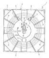
도 1은 본 발명의 내주 길이 측정 장치를 평면시로 예시하는 설명도이다.
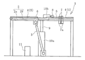
도 2는 도 1의 측정 장치를 측면시(側面視)로 예시하는 설명도이다.
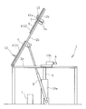
도 3은 도 2의 측정 장치의 치대를 기립시킨 상태를 측면시로 예시하는 설명도이다.
도 4는 2차원 센서에 의해 원형 부재의 내주면까지의 이격 거리를 측정하고 있는 공정을 평면시로 예시하는 설명도이다.
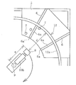
도 5는 도 4의 공정을 측면시로 예시하는 설명도이다.
도 6은 내주 길이의 산출 방법을 예시하는 설명도이다.
도 7은 측정 장치의 다른 실시형태에 있어서의 2차원 센서의 주변을 측면시로 예시하는 설명도이다.BRIEF DESCRIPTION OF DRAWINGS FIG. 1 is an explanatory diagram illustrating an inner circumferential length measuring apparatus of the present invention in plan view. FIG.
Fig. 2 is an explanatory diagram illustrating the measurement apparatus of Fig. 1 as a side view (side view). Fig.
Fig. 3 is an explanatory diagram illustrating, as a side view, a state in which the teeth of the measuring apparatus of Fig. 2 are erected. Fig.
Fig. 4 is an explanatory diagram illustrating, in a plan view, a step of measuring the distance to the inner circumferential surface of the circular member by the two-dimensional sensor. Fig.
5 is an explanatory diagram illustrating the process of FIG. 4 as a side view.
6 is an explanatory diagram illustrating an example of a method of calculating the inner circumferential length.
Fig. 7 is an explanatory diagram illustrating the periphery of a two-dimensional sensor in a side view in another embodiment of the measuring apparatus. Fig.
이하, 본 발명의 원형 부재의 내주 길이 측정 장치를 도면에 나타내는 실시형태에 기초하여 구체적으로 설명한다.BEST MODE FOR CARRYING OUT THE INVENTION Hereinafter, an apparatus for measuring the inner circumference of a circular member of the present invention will be described in detail based on embodiments shown in the drawings.
도 1, 2에 예시하는 본 발명의 원형 부재의 내주 길이 측정 장치(1)(이하, 측정 장치(1)라고 한다)를 이용하여 내주 길이를 측정하는 대상이 되는 것은 타이어 등의 고무 제품에 사용되는 비드 부재나 원통 형상의 고무 부재 등 다양한 원형 부재(12)(원통 부재 및 원환 부재)이다. 도 1에서는 원형 부재(12)를 2점 쇄선으로 나타내고 있다. 측정 시에는, 하나의 원형 부재(12)가 측정 장치(1)에 세트된다.The inner circumferential length measuring device 1 (hereinafter referred to as the measuring device 1) of the present invention illustrated in Figs. 1 and 2 is used for rubber products such as tires (A cylindrical member and a toric member) such as a bead member or a cylindrical rubber member. In Fig. 1, the
측정 장치(1)는, 측정 대상이 되는 원형 부재(12)가 재치되는 치대(4)와, 치대(4)에 대해 이동 가능하게 설치되어 있는 2차원 센서(8)와, 2차원 센서(8)를 회전시키는 회전 구동 기구(10a)와, 2차원 센서(8)에 의한 측정 데이터가 입력되는 연산부(11)를 구비하고 있다. 연산부(11)로서는 여러 가지 컴퓨터 등을 이용할 수 있다.The
수평 상태의 치대(4)에는, 원형 부재(12)가 무구속 상태로 평치된다. 무구속 상태란, 원형 부재(12)에 중력(자중)에 기인하는 외력 이외가 작용하고 있지 않는 상태이다. 이 실시형태에서는, 치대(4)가 원주 방향으로 분할된 복수의 분할체(5)로 형성되어 있다. 각각의 분할체(5)는 그 상면에 상방으로 돌출하는 볼록상 지지부(6)를 갖고 있다. 이 볼록상 지지부(6)의 위에 원형 부재(12)가 무구속 상태로 평치된다. 봉상의 볼록상 지지부(6)는 원형 부재(12)의 반경 방향으로 연재(延在)하고 있다.In the
치대(4)는 복수의 분할체(5)로 형성하지 않고, 분할되어 있지 않은 하나의 판상체로 형성해도 좋다. 볼록상 지지부(6)의 개수는 적어도 3개로 하고, 예를 들어 3개 이상 12개 이하의 적당한 개수로 한다.The
치대(4)는 프레임(2)에 부착되어 있다. 프레임(2)은 베이스 프레임(2a)과 가동 프레임(2b)으로 구성되고, 가동 프레임(2b)의 일 단부는 베이스 프레임(2a)에 회전 가능하게 접속되어 있다. 가동 프레임(2b)은 기복 기구(起伏機構)(3)에 의해 베이스 프레임(2a)에 대해 기복 가능으로 되어 있다. 예를 들어, 도 3에 나타내는 바와 같이, 가동 프레임(2b)은 수평 상태로부터 연직으로 될 때까지의 소정의 각도 범위에서 기복하여 기립 상태로 된다. 이에 따라, 치대(4)도 수평 상태로부터 기립한 상태로 기복 가능으로 되어 있다. 기복 기구(3)로서는 유압 실린더 등을 이용할 수 있다.The teeth (4) are attached to the frame (2). The
치대(4)의 표면에는, 간격을 두고 그 표면으로부터 돌출하는 복수의 돌출부(7)가 설치되어 있다. 각각의 돌출부(7)는 출몰 기구(出沒機構)(7a)에 의해 이동하여 치대(4)의 표면에 대해 출몰 가능으로 되어 있다. 출몰 기구(7a)로서는 에어 실린더나 유압 실린더 등을 이용할 수 있다. 2개의 돌출부(7)가 조(組)가 되어 사용되고, 조가 되는 돌출부(7)끼리의 평면시의 간격 및 위치는 측정 대상이 되는 원형 부재(12)의 내경에 기초하여 설정되어 있다.On the surface of the
2차원 센서(8)는 평면시로 치대(4)의 중앙부에 배치되어 있고, 치대(4)에 평치된 원형 부재(12)의 내측에 배치된다. 2차원 센서(8)는 수평 이동 기구(10b)에 의해 원형 부재(12)의 반경 방향으로 이동 가능으로 되어 있다. 이에 의해, 평치된 원형 부재(12)의 내주면(12a)에 대향하여 배치된 2차원 센서(8)는 내주면(12a)에 대해 근접 및 이반(離反)하는 방향으로 이동할 수 있다.The two-
2차원 센서(8) 및 수평 이동 기구(10b)는 평면시로 치대(4)의 소정 위치(예를 들어, 치대(4)의 중심)에 배치되어 상하로 연재하는 회전축(9)에 지지되어 있다. 회전축(9)은 회전 구동 기구(10a)에 의해 그 축심(軸心)을 중심으로 회전 구동된다. 이에 따라, 2차원 센서(8)는 회전축(9)을 중심으로 하여 회전 구동된다.The two-
2차원 센서(8)로서는 레이저 센서를 이용할 수 있다. 2차원 센서(8)는 조사한 레이저광을 내주면(12a)에서 반사시키고, 반사한 레이저광을 수광함으로써, 2차원 센서(8)로부터 내주면(12a)까지의 이격 거리(d)를 원형 부재(12)에 비접촉으로 측정한다. 2차원 센서(8)는 레이저광을 내주면(12a)의 한 점에만 조사하는 것은 아니고, 한 번에 어느 정도의 길이 범위에 조사하여 2차원 센서(8)와 조사한 범위의 내주면(12a) 사이의 이격 거리(d)를 측정한다.As the two-
2차원 센서(8)에 의해 측정된 이격 거리(d)는 연산부(11)에 입력된다. 또한, 평면시의 회전축(9)(축심)의 위치와 2차원 센서(8)와의 거리(w)도 연산부(11)에 입력된다.The distance d measured by the two-
이하, 이 측정 장치(1)를 이용하여 원형 부재(12)의 내주 길이(L)를 측정하는 순서를 설명한다.Hereinafter, the procedure of measuring the inner circumferential length L of the
치대(4)에 원형 부재(12)를 평치하기 위해서는, 먼저 도 3에 나타내는 바와 같이, 치대(4)를 소정 각도로 하여 기립시킨 상태로 한다. 그리고 원형 부재(12)의 내경에 기초하여 선택한 2개의 돌출부(7)를 치대(4)의 표면으로부터 돌출시킨 상태로 한다. 수평에 대한 기립 상태의 치대(4)의 경사 각도는, 예를 들어 45° 이상 75° 이하로 한다.In order to flatten the
그 다음에, 원형 부재(12)의 내주면(12a)을 치대(4)의 표면으로부터 돌출하고 있는 2개의 돌출부(7)에 계합시킴으로써, 원형 부재(12)를 치대(4)에 이재(移載)한다. 이에 의해, 원형 부재(12)는 내주면(12a)이 2개의 돌출부(7)에 의해 지지되는 동시에 하면(12b)이 볼록상 지지부(6)에 의해 지지된 상태로 된다. 대형 원형 부재(12)의 경우는 크레인 등을 이용하여 이재한다.The
그 다음에, 도 2에 나타내는 바와 같이, 기복 기구(3)에 의해 치대(4)를 도복(倒伏)시켜 수평 상태로 한다. 그 후, 돌출부(7)를 치대(4)의 표면 아래에 몰입시킨 상태로 한다. 이에 의해, 원형 부재(12)는 치대(4)에 무구속 상태로 평치된다.Then, as shown in Fig. 2, the
이와 같이 하여, 원형 부재(12)를 기립한 상태의 치대(4)에 이재함으로써, 대형이고 중량이 큰 원형 부재(12)라도 비교적 스페이스 절약으로 치대(4)로의 이재 작업을 행할 수 있다. 본 발명에 의해 내주 길이(L)를 측정하는 원형 부재(12)의 내경은 특별히 한정되지 않지만, 예를 들어 내경이 500 mm 이상 2000 mm 이하의 범위 정도라도 본 발명을 적용할 수 있다. 기립 상태의 치대(4)에 있어서 2개의 돌출부(7)에 원형 부재(12)의 내주면을 계합시킴으로써, 치대(4)에 대해 원형 부재(12)를 위치 결정할 수 있다.Thus, even when the large and heavy
그리고 기립한 상태의 치대(4)를 수평 상태로 하면, 치대(4)에 대해 소망의 위치에 위치 결정한 상태로 원형 부재(12)를 평치할 수 있다. 따라서 평치했을 때에 원형 부재(12)를 소망의 위치에 위치 결정할 수 있는 위치에 평면시에서의 치대(4)에 있어서의 돌출부(7)의 위치를 설정한다. 예를 들어, 평치했을 때의 원형 부재(12)의 원 중심의 위치가 회전축(9)의 위치로부터 20 mm 이하의 범위로 되도록 평면시에서의 치대(4)에 있어서의 돌출부(7)의 위치를 설정한다. 또한, 조가 되어 사용하는 2개의 돌출부(7)의 평면시의 간격이 지나치게 좁으면, 기립 상태의 치대(4)에서는 원형 부재(12)를 안정하게 보유하기 어려워지기 때문에, 서로의 돌출부(7) 사이에는 적당한 간격을 확보한다.When the standing
원형 부재(12)의 내경이 다르면, 평치했을 때에 원형 부재(12)를 소망의 위치에 위치 결정하기 위한 돌출부(7)의 위치가 다르다. 그래서, 예를 들어 원형 부재(12)의 내경 사이즈마다 사용하는 2개의 돌출부(7)가 적절한 평면시의 위치 및 간격을 설정하고, 그 적절한 위치에 돌출부(7)를 설치하면 좋다. 이 실시형태에서는, 그와 같이 2개의 돌출부(7)의 평면시의 위치 및 간격을 적절히 설정함으로써, 내경 사이즈가 다른 원형 부재(12)라도 평치했을 때에 원형 부재(12)의 원 중심이 대체로 회전축(9)의 위치가 되도록 설정되어 있다. 내경 사이즈가 다른 여러 가지 원형 부재(12)를 치대(4)에 대해 소망의 위치에 정밀도 좋게 위치 결정하여 평치할 수 있기 때문에, 높은 범용성을 갖고 있다.If the inner diameter of the
그 다음에, 원형 부재(12)의 내주면(12a)에 대향하는 2차원 센서(8)를, 필요에 따라, 내주면(12a)을 향해 수평 이동 기구(10b)에 의해 이동시켜 소정의 측정 위치에서 정지시킨다. 즉, 내주면(12a)이 2차원 센서(8)에 의한 측정 가능 범위에 들어가도록 2차원 센서(8)를 이동시킨다. 따라서 치대(4)에 무구속 상태로 평치되어 있는 원형 부재(12)의 내주면(12a)이 당초의 위치에 있는 2차원 센서(8)의 측정 가능 범위에 있다면, 2차원 센서(8)를 수평 이동 기구(10b)에 의해 이동시킬 필요는 없다. 수평 이동 기구(10b)를 채용함으로써, 내경 사이즈가 다른 여러 가지 원형 부재(12)에 대해 2차원 센서(8)를 용이하게 측정 가능 범위에 세트할 수 있다.Next, the two-
그 다음에, 도 4, 도 5에 나타내는 바와 같이, 소정의 측정 위치에 위치 결정한 2차원 센서(8)를 회전축(9)을 중심으로 하여 회전시키면서 2차원 센서(8)로부터 내주면(12a)까지의 이격 거리(d)를 측정하고, 원형 부재(12)의 전체 둘레의 범위에서 이격 거리(d)를 측정한다. 측정한 이격 거리(d)는 연산부(11)에 입력된다. 평면시의 회전축(9)과 소정의 측정 위치에 있는 2차원 센서(8)와의 거리(w)는 파악할 수 있기 때문에, 이 거리(w)도 연산부(11)에 입력된다. 따라서 평면시의 회전축(9)의 축심으로부터 내주면(12a)까지의 거리(w+d)를 원형 부재(12)의 전체 둘레의 범위에서 파악할 수 있다.Next, as shown in Figs. 4 and 5, the two-
여기서, 어떤 위치에서 이격 거리(d)를 측정하고 나서 다음 위치에서 이격 거리(d)를 측정할 때까지 2차원 센서(8)가 회전축(9)을 중심으로 하여 회전하는 각도는 미소 각도(A)(rad)이다. 예를 들어, 이 미소 각도(A)는 2π/15000(rad) 정도이다.Here, the angle at which the two-
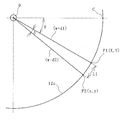
원형 부재(12)의 내주 길이(L)를 산출하는 방법은 몇 가지 있지만, 예를 들어 다음과 같이 산출한다. 도 6에 나타내는 바와 같이, 회전축(9)의 축심을 원점으로 하고, 2차원 센서(8)가 검지하는 원형 부재(12)의 내주면(12a) 상의 임의의 위치(P1)(X, Y)와 위치(P)의 다음에 검지하는 위치(P2)(x, y)를 상정한다. 평면시의 회전축(9)의 축심으로부터 위치(P1)까지의 거리를 w+d1이라고 하고, 회전축(9)의 축심으로부터 위치(P2)까지의 거리를 w+d2라고 한다. 기준점(C)으로부터 위치(P1)까지의 회전 각도를 θ로 하면, 위치(P1)(X, Y)의 좌표는 X=(w+d1)cosθ, Y=(w+d1)sinθ가 된다. 위치(P2)(x, y)의 좌표는 x=(w+d2)cos(θ+A), y=(w+d2)sin(θ+A)가 된다. 기준점(C)의 좌표, 회전 각도(θ), 미소 각도(A), 거리(w+d1), (w+d2)는 파악할 수 있기 때문에, 위치(P1)(X, Y)와 위치(P2)(x, y)의 좌표는 구할 수 있다. 미소 각도(A)에서의 미소 내주 길이(L1)는 L1 = {(X-x)2+(Y-y)2}1/2 과 근사할 수 있다. 그래서 연산부(11)에서는 이 미소 내주 길이(L1)를 원형 부재(12)의 전체 둘레로 적산(積算)함으로써 내주 길이(L)를 산출한다. 또한, 도 6에서는 미소 각도(A)를 설명하기 위해 실제보다도 과장하여 큰 각도로 기재하고 있다.There are several methods for calculating the inner circumferential length L of the
2차원 센서(8)에서는 한 번에 상하 방향의 소정 길이 범위에 레이저광을 조사하고, 2차원 센서(8)와 조사한 범위의 내주면(12a) 사이의 이격 거리(d)를 측정하고 있다. 그래서 내주 길이(L)를 산출할 때의 이격 거리(d)로서는, 예를 들어 내주면(12a)의 상하 방향 중심 위치에서의 이격 거리(d)나 소정의 상하 방향 위치에서의 이격 거리(d) 등 임의의 상하 방향 위치에서의 이격 거리(d)를 채용할 수 있다.The two-
상술한 바와 같이, 본 발명에 의하면, 치대(4)에 무구속 상태로 평치한 원형 부재(12)의 내주 길이(L)를 원형 부재(12)와는 비접촉의2차원 센서(8)를 이용하여 측정한다. 그 때문에, 원형 부재(12)에는 불필요한 부하가 부여되는 경우가 없고, 강제적인 변형은 발생하지 않는다. 따라서 원형 부재(12)의 내주 길이(L)를 정밀도 좋게 측정하는 데 유리해지고 있다.As described above, according to the present invention, the inner circumferential length L of the
이 실시형태에서는, 무구속 상태로 치대(4)에 평치된 원형 부재(12)에 인접하는 치대(4)의 인접 부분의 표면이 2차원 센서(8)가 조사하는 레이저광에 대해 난반사하는 저반사면(6a)으로 구성되어 있다. 구체적으로는, 볼록상 지지부(6)의 상면 및 내주 측 단면은 표면을 미소 요철로 하는 블라스트 처리(blast processing) 등이 시행된 저반사면(6a)으로 되어 있다. 이에 의해, 볼록상 지지부(6)의 상면 및 내주 측 단면에 레이저광이 닿아도 난반사하기 때문에, 2차원 센서(8)에 수광되는 경우가 없다. 이에 수반하여, 핀포인트(pinpoint)가 아니고, 어느 정도의 범위에 레이저광을 조사하는 2차원 센서(8)라도 이격 거리(d)를 측정할 때의 측정 노이즈를 저감할 수 있다.In this embodiment, the surface of the adjacent portion of the
이격 거리(d)를 2차원 센서(8)에 의해 측정할 때는, 돌출부(7)는 치대(4)의 표면 아래에 몰입하고 있다. 그 때문에, 2차원 센서(8)가 조사하는 레이저광을 돌출부(7)가 차단하여 방해하는 경우는 없다.When the separation distance d is measured by the two-
또한, 원형 부재(12)가 상방에 돌출하는 볼록상 지지부(6)에 지지되어 있기 때문에, 2차원 센서(8)의 측정 중심과 원형 부재(12)의 내주면(12a)의 상하 방향 중심을 위치 맞추기가 용이해지고 있다. 그리고 원형 부재(12)의 볼록상 지지부(6)에 지지되어 있지 않은 부분에서는, 내주면(12a)은 공중에 뜬 상태가 되기 때문에, 내주면(12a)에 인접하는 치대(4)의 인접 부분이 최소한으로 된다. 이에 따라, 2차원 센서(8)에 의해 이격 거리(d)를 측정할 때의 측정 노이즈를 저감하는 데 유리하게 되어 있다.
치대(4)는 기복 가능한 구성으로 하지 않고, 수평 상태인 채로 치대(4)를 채용할 수도 있다. 이 사양의 경우는, 프레임(2)의 수평으로 고정된 상면(뼈대)에 치대(4)가 설치된다. 이 치대(4)에 대해, 옆으로 쓰러진 상태의 원형 부재(12)를 재치한다. 대형 원형 부재(12)의 경우는 크레인 등에 의해 원형 부재(12)를 옆으로 쓰러진 상태로 매달아 치대(4)에 이재한다.The
도 7에 예시하는 측정 장치(1)의 다른 실시형태는 앞의 실시형태에 대해 상하 이동 기구(10c)가 추가되어 있을 뿐, 기타의 구성은 동일하다. 상하 이동 기구(10c)는 2차원 센서(8)를 상하 방향에 이동시킨다.Another embodiment of the measuring
상하 이동 기구(10c)로서는 유압 실린더 등을 이용할 수 있다. 내주 길이(L)를 측정하기 전에, 2차원 센서(8)는 상하 이동 기구(10c)에 의해 원형 부재(12)의 내주면(12a)과 대향하는 위치에 위치 결정된다. 이와 같이 하여 측정 위치에 위치 결정된 2차원 센서(8)는 회전축(9)을 중심으로 하여 회전하면서 2차원 센서(8)로부터 내주면(12a)까지의 이격 거리(d)를 측정하고, 원형 부재(12)의 전체 둘레의 범위에서 이격 거리(d)를 측정한다. 원형 부재(12)의 내주 길이(L)를 산출하는 방법은 앞의 실시형태와 동일하다.As the up-and-down moving
이 실시형태에서는 2차원 센서(8)를 내주면(12a)의 상하 위치에 따라 소망의 위치에 정밀도 좋게 위치 결정할 수 있다. 측정을 하지 않는 경우는, 예를 들어 2차원 센서(8)를 치대(4)의 표면이나 프레임(2)의 표면보다도 하방 위치에 이동시켜 대기시킨다. 이에 의해, 이동 중의 원형 부재(12)나 기타의 물건이 2차원 센서(8)에 충돌하여 손상하는 등의 트러블을 회피할 수 있다.In this embodiment, the two-
1: 측정 장치
2: 프레임
2a: 베이스 프레임
2b: 가동 프레임
3: 기복 기구
4: 치대
5: 분할체
6: 볼록상 지지부
6a: 저반사면
7: 돌출부
7a: 출몰 기구
8: 차원 센서
9: 회전축
10a: 회전 구동 기구
10b: 수평 이동 기구
10c: 상하 이동 기구
11: 연산부
12: 원형 부재
12a: 내주면
12b: 하면1: Measuring device
2: frame
2a: base frame
2b: movable frame
3: Relief mechanism
4: Toothbrush
5:
6:
6a: Low reflection surface
7:
7a: Appearance and Attendance Organization
8: Dimension Sensors
9:
10a: rotation driving mechanism
10b: horizontal movement mechanism
10c: a vertical movement mechanism
11:
12: circular member
12a: inner peripheral surface
12b: when
Claims (3)
상기 치대에 무구속 상태로 평치된 원형 부재의 내주면에 대향하여 상기 2차원 센서가 소정의 측정 위치에 배치되고, 상기 원형 부재의 내측의 소정 위치를 중심으로 하여 상기 2차원 센서를 상기 회전 구동 기구에 의해 회전시킴으로써, 상기 2차원 센서로부터 상기 내주면까지 이격 거리가 상기 원형 부재의 전체 둘레의 범위에서 상기 원형 부재에 비접촉으로 측정되고, 측정된 상기 이격 거리와, 평면시의 상기 소정 위치와 상기 2차원 센서와의 거리에 기초하여, 상기 연산부에 의해 상기 원형 부재의 내주 길이가 산출되는 구성으로 한 것을 특징으로 하는 원형 부재의 내주 길이 측정 장치.Dimensional sensor, a rotation driving mechanism for rotating the two-dimensional sensor, and an arithmetic unit for inputting measurement data by the two-dimensional sensor ,
Wherein the two-dimensional sensor is disposed at a predetermined measurement position so as to face an inner circumferential surface of a circular member flattened in an unrestrained state on the tooth, and the two-dimensional sensor is mounted on the rotary drive mechanism The distance from the two-dimensional sensor to the inner circumferential surface is measured in a non-contact manner with respect to the circular member in the range of the entire circumference of the circular member, and the measured distance, the predetermined position in the plane, And the inner circumferential length of the circular member is calculated by the arithmetic unit on the basis of the distance to the dimension sensor.
상기 2차원 센서를 수평 방향으로 이동시키는 수평 이동 기구를 갖고, 이 수평 이동 기구에 의해 상기 2차원 센서가 평면시로 상기 측정 위치에 위치 결정되는 구성으로 한 원형 부재의 내주 길이 측정 장치.The method according to claim 1,
Wherein the two-dimensional sensor is positioned at the measurement position in plan view by the horizontal movement mechanism that moves the two-dimensional sensor in the horizontal direction.
상기 2차원 센서를 상하 방향으로 이동시키는 상하 이동 기구를 갖고, 이 상하 이동 기구에 의해 상기 2차원 센서가 상기 내주면과 대향하는 위치에 위치 결정되는 구성으로 한 내주 길이 측정 장치.3. The method according to claim 1 or 2,
Wherein the two-dimensional sensor is positioned at a position facing the inner circumferential surface by the up-and-down moving mechanism, the up-and-down moving mechanism moving the two-dimensional sensor in the vertical direction.
Applications Claiming Priority (3)
| Application Number | Priority Date | Filing Date | Title |
|---|---|---|---|
| JP2016052614A JP6206527B2 (en) | 2016-03-16 | 2016-03-16 | Device for measuring the inner circumference of a circular member |
| JPJP-P-2016-052614 | 2016-03-16 | ||
| PCT/JP2017/005615 WO2017159193A1 (en) | 2016-03-16 | 2017-02-16 | Internal circumference measurement device for circular member |
Publications (2)
| Publication Number | Publication Date |
|---|---|
| KR20180098338A true KR20180098338A (en) | 2018-09-03 |
| KR102067776B1 KR102067776B1 (en) | 2020-02-11 |
Family
ID=59850217
Family Applications (1)
| Application Number | Title | Priority Date | Filing Date |
|---|---|---|---|
| KR1020187021217A Active KR102067776B1 (en) | 2016-03-16 | 2017-02-16 | Inner length measuring device of circular member |
Country Status (6)
| Country | Link |
|---|---|
| US (1) | US10775154B2 (en) |
| EP (1) | EP3431922B1 (en) |
| JP (1) | JP6206527B2 (en) |
| KR (1) | KR102067776B1 (en) |
| CN (1) | CN108603753B (en) |
| WO (1) | WO2017159193A1 (en) |
Families Citing this family (4)
| Publication number | Priority date | Publication date | Assignee | Title |
|---|---|---|---|---|
| JP6233434B2 (en) * | 2016-03-16 | 2017-11-22 | 横浜ゴム株式会社 | Measuring method of inner circumference of circular member |
| JP6146505B1 (en) * | 2016-03-16 | 2017-06-14 | 横浜ゴム株式会社 | Device for measuring the inner circumference of a circular member |
| US10845192B2 (en) * | 2017-09-13 | 2020-11-24 | Shawn Thomas Lause | Machine tool test fixture |
| CN109341622B (en) * | 2018-12-06 | 2020-10-02 | 燕山大学 | Contact type special vehicle supporting roller height detector |
Citations (3)
| Publication number | Priority date | Publication date | Assignee | Title |
|---|---|---|---|---|
| JPH01195309A (en) * | 1988-01-29 | 1989-08-07 | Sumitomo Rubber Ind Ltd | Measuring instrument for cylindrical body |
| JP2005140726A (en) * | 2003-11-10 | 2005-06-02 | Omron Corp | Thin film measuring method and thin film measuring apparatus |
| JP2012150013A (en) | 2011-01-19 | 2012-08-09 | Sumitomo Rubber Ind Ltd | Inner circumferential length measurement device of bead core |
Family Cites Families (22)
| Publication number | Priority date | Publication date | Assignee | Title |
|---|---|---|---|---|
| JPH061128A (en) | 1992-06-23 | 1994-01-11 | Yokohama Rubber Co Ltd:The | Tire bead inside perimeter measuring instrument |
| JP2759055B2 (en) * | 1994-08-22 | 1998-05-28 | 川崎製鉄株式会社 | Automatic payoff reel deceleration control method |
| US6289600B1 (en) * | 1999-11-02 | 2001-09-18 | United States Pipe & Foundry Company | Non-contact measuring device |
| US7251580B2 (en) | 2003-10-20 | 2007-07-31 | Mitutoyo Corporation | Method for measuring curved surface of workpiece, program and medium thereof |
| GB0605796D0 (en) | 2006-03-23 | 2006-05-03 | Renishaw Plc | Apparatus and method of measuring workpieces |
| JP5120625B2 (en) * | 2008-03-07 | 2013-01-16 | アイシン精機株式会社 | Inner surface measuring device |
| JP2010048731A (en) * | 2008-08-25 | 2010-03-04 | Toyota Motor Corp | Measuring device and measuring method of cross-sectional shape |
| JP5269698B2 (en) * | 2009-06-10 | 2013-08-21 | 株式会社ミツトヨ | Roundness measuring device |
| KR101118957B1 (en) * | 2009-12-29 | 2012-03-05 | 주식회사 성우하이텍 | Table jig for door sanding |
| CN202432959U (en) * | 2011-12-26 | 2012-09-12 | 宝山钢铁股份有限公司 | Multifunctional disc scissor blade detection rack |
| JP2013134176A (en) * | 2011-12-27 | 2013-07-08 | Sharp Corp | Imaging apparatus and imaging method |
| JP2013186009A (en) * | 2012-03-08 | 2013-09-19 | Toyota Motor Corp | Calibration method of shape measurement device |
| JP6169339B2 (en) | 2012-10-04 | 2017-07-26 | 株式会社日立製作所 | Shape measuring method and apparatus |
| CN102980558A (en) * | 2012-12-07 | 2013-03-20 | 辽宁工程技术大学 | Intelligent tunnel section measurement device and method for mine based on polar coordinate integral |
| CN102997851B (en) * | 2012-12-11 | 2015-08-05 | 三一重工股份有限公司 | The circumference measuring method of spiral-tube and device for measuring circumference |
| CN104180763A (en) * | 2013-05-24 | 2014-12-03 | 南开大学 | Non-contact measurement apparatus of inner and outer diameters of large-diameter circular ring type component |
| CN103278100B (en) * | 2013-06-19 | 2016-06-22 | 天津大学 | A kind of bore diameter measuring method based on noncontacting proximity sensor combination |
| WO2015008820A1 (en) * | 2013-07-19 | 2015-01-22 | 株式会社ニコン | Shape measurement device, structural object production system, shape measurement method, structural object production method, shape measurement program, and recording medium |
| CN203615897U (en) * | 2013-09-23 | 2014-05-28 | 北京石油化工学院 | Pipeline internal diameter measure apparatus based on displacement sensor |
| CN204325905U (en) * | 2014-10-28 | 2015-05-13 | 中铁二院工程集团有限责任公司 | For the dynamometry elastic body of multidirectional dynamometry ball shaped steel bearing |
| JP6146505B1 (en) * | 2016-03-16 | 2017-06-14 | 横浜ゴム株式会社 | Device for measuring the inner circumference of a circular member |
| JP6233434B2 (en) * | 2016-03-16 | 2017-11-22 | 横浜ゴム株式会社 | Measuring method of inner circumference of circular member |
-
2016
- 2016-03-16 JP JP2016052614A patent/JP6206527B2/en active Active
-
2017
- 2017-02-16 WO PCT/JP2017/005615 patent/WO2017159193A1/en not_active Ceased
- 2017-02-16 EP EP17766200.4A patent/EP3431922B1/en active Active
- 2017-02-16 KR KR1020187021217A patent/KR102067776B1/en active Active
- 2017-02-16 US US16/085,561 patent/US10775154B2/en active Active
- 2017-02-16 CN CN201780010562.6A patent/CN108603753B/en active Active
Patent Citations (3)
| Publication number | Priority date | Publication date | Assignee | Title |
|---|---|---|---|---|
| JPH01195309A (en) * | 1988-01-29 | 1989-08-07 | Sumitomo Rubber Ind Ltd | Measuring instrument for cylindrical body |
| JP2005140726A (en) * | 2003-11-10 | 2005-06-02 | Omron Corp | Thin film measuring method and thin film measuring apparatus |
| JP2012150013A (en) | 2011-01-19 | 2012-08-09 | Sumitomo Rubber Ind Ltd | Inner circumferential length measurement device of bead core |
Non-Patent Citations (1)
| Title |
|---|
| 일본 공개특허공보 제(평)6-1128호 |
Also Published As
| Publication number | Publication date |
|---|---|
| CN108603753B (en) | 2020-08-04 |
| EP3431922A4 (en) | 2019-09-25 |
| JP6206527B2 (en) | 2017-10-04 |
| EP3431922A1 (en) | 2019-01-23 |
| JP2017166982A (en) | 2017-09-21 |
| US10775154B2 (en) | 2020-09-15 |
| EP3431922B1 (en) | 2022-03-02 |
| WO2017159193A1 (en) | 2017-09-21 |
| US20190154433A1 (en) | 2019-05-23 |
| KR102067776B1 (en) | 2020-02-11 |
| CN108603753A (en) | 2018-09-28 |
Similar Documents
| Publication | Publication Date | Title |
|---|---|---|
| CN106415197B (en) | Method for correcting surface shape data of annular rotating body and apparatus for inspecting appearance of annular rotating body | |
| JP5946424B2 (en) | Tire testing machine | |
| KR20180098338A (en) | Apparatus for measuring the inner circumference of a circular member | |
| KR20180097706A (en) | Measuring inner circumference length of circular member | |
| CN105415990A (en) | Machine for fitting and removing tires and method for operating the machine | |
| JP6420639B2 (en) | Tread shape measurement method | |
| CN103250024B (en) | For detecting the shape of wheel and/or the method for size repairing on plant machinery or analog | |
| KR20180097705A (en) | Apparatus for measuring the inner circumference of a circular member | |
| JP2023131124A (en) | Surface shape measuring device | |
| KR20150088924A (en) | Roundness measuring system of large bearing | |
| JP6265864B2 (en) | Tire testing equipment | |
| JP6735254B2 (en) | Device and method for calculating tire dynamic load radius | |
| CN207317764U (en) | A kind of new three-coordinates measuring machine | |
| US20200263975A1 (en) | Shape Measuring Device for Hose Connector Fitting | |
| TWM616494U (en) | Non-contact type ring object roundness measurement device | |
| JP2005127810A5 (en) |
Legal Events
| Date | Code | Title | Description |
|---|---|---|---|
| A201 | Request for examination | ||
| PA0105 | International application |
St.27 status event code: A-0-1-A10-A15-nap-PA0105 |
|
| PA0201 | Request for examination |
St.27 status event code: A-1-2-D10-D11-exm-PA0201 |
|
| PG1501 | Laying open of application |
St.27 status event code: A-1-1-Q10-Q12-nap-PG1501 |
|
| E902 | Notification of reason for refusal | ||
| PE0902 | Notice of grounds for rejection |
St.27 status event code: A-1-2-D10-D21-exm-PE0902 |
|
| P11-X000 | Amendment of application requested |
St.27 status event code: A-2-2-P10-P11-nap-X000 |
|
| P13-X000 | Application amended |
St.27 status event code: A-2-2-P10-P13-nap-X000 |
|
| E701 | Decision to grant or registration of patent right | ||
| PE0701 | Decision of registration |
St.27 status event code: A-1-2-D10-D22-exm-PE0701 |
|
| GRNT | Written decision to grant | ||
| PR0701 | Registration of establishment |
St.27 status event code: A-2-4-F10-F11-exm-PR0701 |
|
| PR1002 | Payment of registration fee |
St.27 status event code: A-2-2-U10-U12-oth-PR1002 Fee payment year number: 1 |
|
| PG1601 | Publication of registration |
St.27 status event code: A-4-4-Q10-Q13-nap-PG1601 |
|
| PR1001 | Payment of annual fee |
St.27 status event code: A-4-4-U10-U11-oth-PR1001 Fee payment year number: 4 |
|
| PR1001 | Payment of annual fee |
St.27 status event code: A-4-4-U10-U11-oth-PR1001 Fee payment year number: 5 |
|
| R18-X000 | Changes to party contact information recorded |
St.27 status event code: A-5-5-R10-R18-oth-X000 |
|
| PR1001 | Payment of annual fee |
St.27 status event code: A-4-4-U10-U11-oth-PR1001 Fee payment year number: 6 |
|
| U11 | Full renewal or maintenance fee paid |
Free format text: ST27 STATUS EVENT CODE: A-4-4-U10-U11-OTH-PR1001 (AS PROVIDED BY THE NATIONAL OFFICE) Year of fee payment: 6 |