KR20180098293A - Autonomous docking station for drones - Google Patents
Autonomous docking station for drones Download PDFInfo
- Publication number
- KR20180098293A KR20180098293A KR1020187019750A KR20187019750A KR20180098293A KR 20180098293 A KR20180098293 A KR 20180098293A KR 1020187019750 A KR1020187019750 A KR 1020187019750A KR 20187019750 A KR20187019750 A KR 20187019750A KR 20180098293 A KR20180098293 A KR 20180098293A
- Authority
- KR
- South Korea
- Prior art keywords
- drones
- cell
- station
- landing
- docking
- Prior art date
- Legal status (The legal status is an assumption and is not a legal conclusion. Google has not performed a legal analysis and makes no representation as to the accuracy of the status listed.)
- Withdrawn
Links
Images


Classifications
-
- B—PERFORMING OPERATIONS; TRANSPORTING
- B64—AIRCRAFT; AVIATION; COSMONAUTICS
- B64F—GROUND OR AIRCRAFT-CARRIER-DECK INSTALLATIONS SPECIALLY ADAPTED FOR USE IN CONNECTION WITH AIRCRAFT; DESIGNING, MANUFACTURING, ASSEMBLING, CLEANING, MAINTAINING OR REPAIRING AIRCRAFT, NOT OTHERWISE PROVIDED FOR; HANDLING, TRANSPORTING, TESTING OR INSPECTING AIRCRAFT COMPONENTS, NOT OTHERWISE PROVIDED FOR
- B64F1/00—Ground or aircraft-carrier-deck installations
- B64F1/007—Helicopter portable landing pads
-
- B60L11/1829—
-
- B60L11/1838—
-
- B—PERFORMING OPERATIONS; TRANSPORTING
- B60—VEHICLES IN GENERAL
- B60L—PROPULSION OF ELECTRICALLY-PROPELLED VEHICLES; SUPPLYING ELECTRIC POWER FOR AUXILIARY EQUIPMENT OF ELECTRICALLY-PROPELLED VEHICLES; ELECTRODYNAMIC BRAKE SYSTEMS FOR VEHICLES IN GENERAL; MAGNETIC SUSPENSION OR LEVITATION FOR VEHICLES; MONITORING OPERATING VARIABLES OF ELECTRICALLY-PROPELLED VEHICLES; ELECTRIC SAFETY DEVICES FOR ELECTRICALLY-PROPELLED VEHICLES
- B60L53/00—Methods of charging batteries, specially adapted for electric vehicles; Charging stations or on-board charging equipment therefor; Exchange of energy storage elements in electric vehicles
- B60L53/30—Constructional details of charging stations
- B60L53/35—Means for automatic or assisted adjustment of the relative position of charging devices and vehicles
- B60L53/38—Means for automatic or assisted adjustment of the relative position of charging devices and vehicles specially adapted for charging by inductive energy transfer
-
- B—PERFORMING OPERATIONS; TRANSPORTING
- B60—VEHICLES IN GENERAL
- B60L—PROPULSION OF ELECTRICALLY-PROPELLED VEHICLES; SUPPLYING ELECTRIC POWER FOR AUXILIARY EQUIPMENT OF ELECTRICALLY-PROPELLED VEHICLES; ELECTRODYNAMIC BRAKE SYSTEMS FOR VEHICLES IN GENERAL; MAGNETIC SUSPENSION OR LEVITATION FOR VEHICLES; MONITORING OPERATING VARIABLES OF ELECTRICALLY-PROPELLED VEHICLES; ELECTRIC SAFETY DEVICES FOR ELECTRICALLY-PROPELLED VEHICLES
- B60L53/00—Methods of charging batteries, specially adapted for electric vehicles; Charging stations or on-board charging equipment therefor; Exchange of energy storage elements in electric vehicles
- B60L53/60—Monitoring or controlling charging stations
-
- B—PERFORMING OPERATIONS; TRANSPORTING
- B64—AIRCRAFT; AVIATION; COSMONAUTICS
- B64C—AEROPLANES; HELICOPTERS
- B64C39/00—Aircraft not otherwise provided for
- B64C39/02—Aircraft not otherwise provided for characterised by special use
- B64C39/024—Aircraft not otherwise provided for characterised by special use of the remote controlled vehicle type, i.e. RPV
-
- B—PERFORMING OPERATIONS; TRANSPORTING
- B64—AIRCRAFT; AVIATION; COSMONAUTICS
- B64F—GROUND OR AIRCRAFT-CARRIER-DECK INSTALLATIONS SPECIALLY ADAPTED FOR USE IN CONNECTION WITH AIRCRAFT; DESIGNING, MANUFACTURING, ASSEMBLING, CLEANING, MAINTAINING OR REPAIRING AIRCRAFT, NOT OTHERWISE PROVIDED FOR; HANDLING, TRANSPORTING, TESTING OR INSPECTING AIRCRAFT COMPONENTS, NOT OTHERWISE PROVIDED FOR
- B64F1/00—Ground or aircraft-carrier-deck installations
- B64F1/12—Ground or aircraft-carrier-deck installations for anchoring aircraft
- B64F1/125—Mooring or ground handling devices for helicopters
-
- B—PERFORMING OPERATIONS; TRANSPORTING
- B64—AIRCRAFT; AVIATION; COSMONAUTICS
- B64F—GROUND OR AIRCRAFT-CARRIER-DECK INSTALLATIONS SPECIALLY ADAPTED FOR USE IN CONNECTION WITH AIRCRAFT; DESIGNING, MANUFACTURING, ASSEMBLING, CLEANING, MAINTAINING OR REPAIRING AIRCRAFT, NOT OTHERWISE PROVIDED FOR; HANDLING, TRANSPORTING, TESTING OR INSPECTING AIRCRAFT COMPONENTS, NOT OTHERWISE PROVIDED FOR
- B64F1/00—Ground or aircraft-carrier-deck installations
- B64F1/18—Visual or acoustic landing aids
- B64F1/20—Arrangement of optical beacons
-
- B—PERFORMING OPERATIONS; TRANSPORTING
- B64—AIRCRAFT; AVIATION; COSMONAUTICS
- B64F—GROUND OR AIRCRAFT-CARRIER-DECK INSTALLATIONS SPECIALLY ADAPTED FOR USE IN CONNECTION WITH AIRCRAFT; DESIGNING, MANUFACTURING, ASSEMBLING, CLEANING, MAINTAINING OR REPAIRING AIRCRAFT, NOT OTHERWISE PROVIDED FOR; HANDLING, TRANSPORTING, TESTING OR INSPECTING AIRCRAFT COMPONENTS, NOT OTHERWISE PROVIDED FOR
- B64F1/00—Ground or aircraft-carrier-deck installations
- B64F1/22—Ground or aircraft-carrier-deck installations for handling aircraft
- B64F1/222—Ground or aircraft-carrier-deck installations for handling aircraft for storing aircraft, e.g. in hangars
-
- B—PERFORMING OPERATIONS; TRANSPORTING
- B64—AIRCRAFT; AVIATION; COSMONAUTICS
- B64F—GROUND OR AIRCRAFT-CARRIER-DECK INSTALLATIONS SPECIALLY ADAPTED FOR USE IN CONNECTION WITH AIRCRAFT; DESIGNING, MANUFACTURING, ASSEMBLING, CLEANING, MAINTAINING OR REPAIRING AIRCRAFT, NOT OTHERWISE PROVIDED FOR; HANDLING, TRANSPORTING, TESTING OR INSPECTING AIRCRAFT COMPONENTS, NOT OTHERWISE PROVIDED FOR
- B64F1/00—Ground or aircraft-carrier-deck installations
- B64F1/36—Other airport installations
- B64F1/362—Installations for supplying conditioned air to parked aircraft
-
- B—PERFORMING OPERATIONS; TRANSPORTING
- B64—AIRCRAFT; AVIATION; COSMONAUTICS
- B64U—UNMANNED AERIAL VEHICLES [UAV]; EQUIPMENT THEREFOR
- B64U50/00—Propulsion; Power supply
- B64U50/30—Supply or distribution of electrical power
- B64U50/37—Charging when not in flight
-
- B—PERFORMING OPERATIONS; TRANSPORTING
- B64—AIRCRAFT; AVIATION; COSMONAUTICS
- B64U—UNMANNED AERIAL VEHICLES [UAV]; EQUIPMENT THEREFOR
- B64U50/00—Propulsion; Power supply
- B64U50/30—Supply or distribution of electrical power
- B64U50/39—Battery swapping
-
- B—PERFORMING OPERATIONS; TRANSPORTING
- B64—AIRCRAFT; AVIATION; COSMONAUTICS
- B64U—UNMANNED AERIAL VEHICLES [UAV]; EQUIPMENT THEREFOR
- B64U80/00—Transport or storage specially adapted for UAVs
- B64U80/10—Transport or storage specially adapted for UAVs with means for moving the UAV to a supply or launch location, e.g. robotic arms or carousels
-
- B—PERFORMING OPERATIONS; TRANSPORTING
- B64—AIRCRAFT; AVIATION; COSMONAUTICS
- B64U—UNMANNED AERIAL VEHICLES [UAV]; EQUIPMENT THEREFOR
- B64U80/00—Transport or storage specially adapted for UAVs
- B64U80/70—Transport or storage specially adapted for UAVs in containers
-
- G—PHYSICS
- G08—SIGNALLING
- G08G—TRAFFIC CONTROL SYSTEMS
- G08G5/00—Traffic control systems for aircraft
- G08G5/50—Navigation or guidance aids
- G08G5/54—Navigation or guidance aids for approach or landing
-
- G—PHYSICS
- G08—SIGNALLING
- G08G—TRAFFIC CONTROL SYSTEMS
- G08G5/00—Traffic control systems for aircraft
- G08G5/50—Navigation or guidance aids
- G08G5/56—Navigation or guidance aids for two or more aircraft
-
- G—PHYSICS
- G08—SIGNALLING
- G08G—TRAFFIC CONTROL SYSTEMS
- G08G5/00—Traffic control systems for aircraft
- G08G5/70—Arrangements for monitoring traffic-related situations or conditions
- G08G5/76—Arrangements for monitoring traffic-related situations or conditions for monitoring atmospheric conditions
-
- H—ELECTRICITY
- H02—GENERATION; CONVERSION OR DISTRIBUTION OF ELECTRIC POWER
- H02J—ELECTRIC POWER NETWORKS; CIRCUIT ARRANGEMENTS OR SYSTEMS FOR SUPPLYING OR DISTRIBUTING ELECTRIC POWER; SYSTEMS FOR STORING ELECTRIC ENERGY
- H02J7/00—Circuit arrangements for charging or discharging batteries or for supplying loads from batteries
- H02J7/34—Parallel operation in networks using both storage and other DC sources, e.g. providing buffering
- H02J7/35—Parallel operation in networks using both storage and other DC sources, e.g. providing buffering with light sensitive cells
-
- H—ELECTRICITY
- H02—GENERATION; CONVERSION OR DISTRIBUTION OF ELECTRIC POWER
- H02S—GENERATION OF ELECTRIC POWER BY CONVERSION OF INFRARED RADIATION, VISIBLE LIGHT OR ULTRAVIOLET LIGHT, e.g. USING PHOTOVOLTAIC [PV] MODULES
- H02S20/00—Supporting structures for PV modules
- H02S20/20—Supporting structures directly fixed to an immovable object
-
- H—ELECTRICITY
- H02—GENERATION; CONVERSION OR DISTRIBUTION OF ELECTRIC POWER
- H02S—GENERATION OF ELECTRIC POWER BY CONVERSION OF INFRARED RADIATION, VISIBLE LIGHT OR ULTRAVIOLET LIGHT, e.g. USING PHOTOVOLTAIC [PV] MODULES
- H02S20/00—Supporting structures for PV modules
- H02S20/30—Supporting structures being movable or adjustable, e.g. for angle adjustment
-
- B—PERFORMING OPERATIONS; TRANSPORTING
- B60—VEHICLES IN GENERAL
- B60L—PROPULSION OF ELECTRICALLY-PROPELLED VEHICLES; SUPPLYING ELECTRIC POWER FOR AUXILIARY EQUIPMENT OF ELECTRICALLY-PROPELLED VEHICLES; ELECTRODYNAMIC BRAKE SYSTEMS FOR VEHICLES IN GENERAL; MAGNETIC SUSPENSION OR LEVITATION FOR VEHICLES; MONITORING OPERATING VARIABLES OF ELECTRICALLY-PROPELLED VEHICLES; ELECTRIC SAFETY DEVICES FOR ELECTRICALLY-PROPELLED VEHICLES
- B60L2200/00—Type of vehicles
- B60L2200/10—Air crafts
-
- B64C2201/066—
-
- B64C2201/201—
-
- B—PERFORMING OPERATIONS; TRANSPORTING
- B64—AIRCRAFT; AVIATION; COSMONAUTICS
- B64U—UNMANNED AERIAL VEHICLES [UAV]; EQUIPMENT THEREFOR
- B64U10/00—Type of UAV
- B64U10/10—Rotorcrafts
- B64U10/13—Flying platforms
- B64U10/14—Flying platforms with four distinct rotor axes, e.g. quadcopters
-
- B—PERFORMING OPERATIONS; TRANSPORTING
- B64—AIRCRAFT; AVIATION; COSMONAUTICS
- B64U—UNMANNED AERIAL VEHICLES [UAV]; EQUIPMENT THEREFOR
- B64U2201/00—UAVs characterised by their flight controls
- B64U2201/20—Remote controls
-
- Y—GENERAL TAGGING OF NEW TECHNOLOGICAL DEVELOPMENTS; GENERAL TAGGING OF CROSS-SECTIONAL TECHNOLOGIES SPANNING OVER SEVERAL SECTIONS OF THE IPC; TECHNICAL SUBJECTS COVERED BY FORMER USPC CROSS-REFERENCE ART COLLECTIONS [XRACs] AND DIGESTS
- Y02—TECHNOLOGIES OR APPLICATIONS FOR MITIGATION OR ADAPTATION AGAINST CLIMATE CHANGE
- Y02E—REDUCTION OF GREENHOUSE GAS [GHG] EMISSIONS, RELATED TO ENERGY GENERATION, TRANSMISSION OR DISTRIBUTION
- Y02E10/00—Energy generation through renewable energy sources
- Y02E10/50—Photovoltaic [PV] energy
-
- Y—GENERAL TAGGING OF NEW TECHNOLOGICAL DEVELOPMENTS; GENERAL TAGGING OF CROSS-SECTIONAL TECHNOLOGIES SPANNING OVER SEVERAL SECTIONS OF THE IPC; TECHNICAL SUBJECTS COVERED BY FORMER USPC CROSS-REFERENCE ART COLLECTIONS [XRACs] AND DIGESTS
- Y02—TECHNOLOGIES OR APPLICATIONS FOR MITIGATION OR ADAPTATION AGAINST CLIMATE CHANGE
- Y02T—CLIMATE CHANGE MITIGATION TECHNOLOGIES RELATED TO TRANSPORTATION
- Y02T10/00—Road transport of goods or passengers
- Y02T10/60—Other road transportation technologies with climate change mitigation effect
- Y02T10/70—Energy storage systems for electromobility, e.g. batteries
-
- Y—GENERAL TAGGING OF NEW TECHNOLOGICAL DEVELOPMENTS; GENERAL TAGGING OF CROSS-SECTIONAL TECHNOLOGIES SPANNING OVER SEVERAL SECTIONS OF THE IPC; TECHNICAL SUBJECTS COVERED BY FORMER USPC CROSS-REFERENCE ART COLLECTIONS [XRACs] AND DIGESTS
- Y02—TECHNOLOGIES OR APPLICATIONS FOR MITIGATION OR ADAPTATION AGAINST CLIMATE CHANGE
- Y02T—CLIMATE CHANGE MITIGATION TECHNOLOGIES RELATED TO TRANSPORTATION
- Y02T10/00—Road transport of goods or passengers
- Y02T10/60—Other road transportation technologies with climate change mitigation effect
- Y02T10/7072—Electromobility specific charging systems or methods for batteries, ultracapacitors, supercapacitors or double-layer capacitors
-
- Y—GENERAL TAGGING OF NEW TECHNOLOGICAL DEVELOPMENTS; GENERAL TAGGING OF CROSS-SECTIONAL TECHNOLOGIES SPANNING OVER SEVERAL SECTIONS OF THE IPC; TECHNICAL SUBJECTS COVERED BY FORMER USPC CROSS-REFERENCE ART COLLECTIONS [XRACs] AND DIGESTS
- Y02—TECHNOLOGIES OR APPLICATIONS FOR MITIGATION OR ADAPTATION AGAINST CLIMATE CHANGE
- Y02T—CLIMATE CHANGE MITIGATION TECHNOLOGIES RELATED TO TRANSPORTATION
- Y02T50/00—Aeronautics or air transport
- Y02T50/50—On board measures aiming to increase energy efficiency
-
- Y02T50/53—
-
- Y—GENERAL TAGGING OF NEW TECHNOLOGICAL DEVELOPMENTS; GENERAL TAGGING OF CROSS-SECTIONAL TECHNOLOGIES SPANNING OVER SEVERAL SECTIONS OF THE IPC; TECHNICAL SUBJECTS COVERED BY FORMER USPC CROSS-REFERENCE ART COLLECTIONS [XRACs] AND DIGESTS
- Y02—TECHNOLOGIES OR APPLICATIONS FOR MITIGATION OR ADAPTATION AGAINST CLIMATE CHANGE
- Y02T—CLIMATE CHANGE MITIGATION TECHNOLOGIES RELATED TO TRANSPORTATION
- Y02T90/00—Enabling technologies or technologies with a potential or indirect contribution to GHG emissions mitigation
- Y02T90/10—Technologies relating to charging of electric vehicles
- Y02T90/12—Electric charging stations
Landscapes
- Engineering & Computer Science (AREA)
- Aviation & Aerospace Engineering (AREA)
- Mechanical Engineering (AREA)
- Remote Sensing (AREA)
- Physics & Mathematics (AREA)
- Transportation (AREA)
- Chemical & Material Sciences (AREA)
- Combustion & Propulsion (AREA)
- Acoustics & Sound (AREA)
- General Physics & Mathematics (AREA)
- Power Engineering (AREA)
- Robotics (AREA)
- Charge And Discharge Circuits For Batteries Or The Like (AREA)
- Radar, Positioning & Navigation (AREA)
- Control Of Position, Course, Altitude, Or Attitude Of Moving Bodies (AREA)
- Life Sciences & Earth Sciences (AREA)
- Atmospheric Sciences (AREA)
Abstract
드론/드론들을 위한 자율 착륙/이륙, 저장, 재충전 및/또는 배터리 교체를 가능하게 하는 도킹 스테이션/스테이션들에 의해, 드론들의 짧은 배터리 수명 및 고립되거나 떨어져 있는 서비스 지역들에서의 작동 문제에 대한 솔루션. 스테이션은 하나 이상의 착륙/이륙 셀; 적어도 두 개의 도킹/저장 셀; 상기 착륙/이륙 셀들 및 도킹/저장 셀들 내에서 상기 드론들을 수송하도록 구성된 전이 폐쇄 루프 시스템; 및 상기 멀티 셀 스테이션의 자율 제어, 작동 및 관리를 위해 구성된 제어 수단을 포함하되, 상기 하나 이상의 착륙/이륙 셀 및 적어도 두 개의 도킹/저장 셀의 각각은 이웃하는 셀들과 적어도 두 측을 공유하는, 드론들을 위한 멀티 셀 스테이션이다. 저장된 드론들을 재충전시키기 위한 재충전 메커니즘 및 드론들을 스테이션의 셀들 내에서 순환시키기 위한 전이 메커니즘이 또한 제공된다.Solutions for drones' short battery life and operational problems in isolated or remote service areas by docking stations / stations allowing autonomous landing / takeoff, storage, recharging and / or battery replacement for drones / drones . The station may include one or more landing / takeoff cells; At least two docking / storing cells; A transition closed loop system configured to transport the drones within the landing / takeoff cells and docking / storing cells; And control means configured for autonomous control, operation and management of the multi-cell station, wherein each of the one or more landing / takeoff cells and at least two docking / storage cells share at least two sides with neighboring cells, It is a multi-cell station for drones. A recharging mechanism for recharging the stored drones and a transition mechanism for circulating the drones in the cells of the station are also provided.
Description
본 발명은 드론 도킹 스테이션들과 관련된다. 특히, 본 발명은 원격 무선 감속 및 제어를 사용하여 자동 착륙, 이륙, 도킹 및 전기 재충전을 하기 위한 모듈식, 가변 도킹 스테이션들과 관련되며, 이들은 특히 연속적인 미션들 또는 고립되거나 떨어져 있는 지역들의 서비스에 바람직하다.The present invention relates to drone docking stations. In particular, the invention relates to modular, variable docking stations for automatic landing, takeoff, docking and electrical recharging using remote wireless deceleration and control, which are particularly useful for continuous missions or services of isolated or remote areas .
드론들은 주로 그것들의 자율 역량들에 기인하여 광범위한 적용을 위해 사용되고 있다. 드론들은 이미 농업, 보안, 소포 수송, 3D 매핑, 파이프라인 모니터링, 구성, 그 보다 더욱 많은 것을 포함하여 다양한 산업을 지원하기 위해 이용되고 있다.. 드론들을 위한 자율 적용들은 참으로 무궁무진하나, 그것들은 보통 그것들의 짧은 배터리 수명에 의해 충족되지 않는 비행 시간을 필요로 한다. 구체적으로, 드론 배터리는 단지 15분 내지 20분 사이의 비행 시간을 제공할 수 있으며(유상하중, 풍황 등에 따라) 이는 가장 획기적인 자율 적용이라도 매 15분마다 매우 번거롭게 만들거나 그에 따라 드론은 수동으로 재충전되기 위해 착륙해야만 한다. 이러한 그리고 몇몇 다른 요인은 상업적 용도들을 위한 드론들의 사용을 번거롭게 그리고 드론들을 착륙, 재충전 및 재론치시켜야 하는 파일럿들에 의존하게 만든다.Drones are mainly used for a wide range of applications due to their autonomous capabilities. Drones are already being used to support a variety of industries, including agriculture, security, parcel transport, 3D mapping, pipeline monitoring, configuration, and much more. Autonomous applications for drones are indeed infinite, They usually require flight times that are not met by their short battery life. Specifically, the drone battery can provide a flight time of only 15 to 20 minutes (depending on the weight of the cargo, the ebb and flow, etc.), which makes it very cumbersome every 15 minutes even with the most dramatic autonomous applications, To land. These and some other factors make the use of drones for commercial uses cumbersome and dependent on pilots who have to land, reload, and recall drones.
순차적인 론치에 가능성 있게 유용한, 복수의 드론의 거처가 되는 스테이션들은 종래 기술, 구체적으로 WO 2016/130112 및 WO 2015/195175에 설명된다. 그러나, 이러한 스테이션들은 여전히 드론 배터리의 인간 조력 충전을 필요로 하고 각 스테이션의 자원들의 적어도 누적된 양을 소모하는 독립형 착륙 및 이륙 스테이션들의 집적 구조들이다.Stations that are potentially useful in sequential launches and serve as a plurality of drones are described in the prior art, specifically WO 2016/130112 and WO 2015/195175. However, these stations are still integrated structures of stand-alone landing and take-off stations that require human assisted charging of the drone batteries and consume at least a cumulative amount of resources of each station.
따라서, 본 발명의 목적은 종래 기술의 결점들을 극복하는 드론들의 착륙, 이륙, 재충전 및 도킹을 위한 멀티 셀 스테이션을 제공하는 것이다. It is therefore an object of the present invention to provide a multi-cell station for landing, take-off, recharging and docking of drones that overcomes the drawbacks of the prior art.
본 발명의 또 다른 목적은 드론들의 자율 착륙, 이륙, 재충전 및 도킹을 위한 멀티 셀 스테이션에 단지 원격 감독 및 제어를 제공하는 것이다.It is a further object of the present invention to provide only remote monitoring and control of the multi-cell station for autonomous landing, take-off, recharging and docking of drones.
본 발명의 또 다른 목적은 드론들의 자율 착륙, 이륙, 재충전 및 도킹을 위한 모듈식, 가변 멀티 셀 스테이션을 제공하는 것이다.It is another object of the present invention to provide a modular, variable multi-cell station for autonomous landing, take-off, recharging and docking of drones.
본 발명의 이러한 그리고 다른 목적들 및 실시예들은 본 설명이 진행됨에 따라 명백해질 것이다.These and other objects and embodiments of the present invention will become apparent as the description proceeds.
하나의 양상에서, 본 발명은 드론/드론들을 위한 자율 착륙/이륙, 저장, 재충전 및/또는 배터리 교체를 가능하게 하는 도킹 스테이션/스테이션들에 의해, 드론들의 짧은 배터리 수명 및 고립되거나 떨어져 있는 서비스 지역들에서의 작동 문제에 대한 솔루션을 제공한다.In one aspect, the present invention is directed to a docking station / station that enables autonomous landing / takeoff, storage, recharging, and / or battery replacement for drones / drones, To provide a solution to the operational problems in the system.
이러한 솔루션은 특히 민간 드론들에 대해, 완전 자율 미션들을 가능하게 한다. 나아가, 드론들의 멀티 도킹을 위한 이러한 솔루션은 파일럿의 중개를 탈피하고 드론들의 이륙, 비행, 정확한 착륙, 재충전, 미션 업로드 및 저장을 용이하게 함으로써 완전한 미션 자율성을 가능하게 한다. 이는 물론, 유용성을 크게 향상시키고 운용 비용을 크게 줄인다.These solutions enable fully autonomous missions, especially for private drones. Furthermore, this solution for multi-docking of drones allows complete mission autonomy by breaking out the pilot's mediation and facilitating take-off, flying, accurate landing, recharging, mission upload and storage of drones. This, of course, greatly improves usability and greatly reduces operating costs.
상기한 내용을 고려하여, 본 발명은 하나의 특정한 실시예에서 드론들을 위한 멀티 셀 스테이션을 제공하며, 상기 멀티 셀 스테이션은: In view of the above, the present invention provides a multi-cell station for drones in one particular embodiment, the multi-cell station comprising:
하나 이상의 착륙/이륙 셀; One or more landing / takeoff cells;
적어도 두 개의 도킹/저장 셀; At least two docking / storing cells;
상기 착륙/이륙 셀들 및 도킹/저장 셀들 내에서 상기 드론들을 수송하도록 구성된 전이 폐쇄 루프 시스템; 및 A transition closed loop system configured to transport the drones within the landing / takeoff cells and docking / storing cells; And
상기 멀티 셀 스테이션의 자율 제어, 작동 및 관리를 위해 구성된 제어 수단을 포함하되, And control means configured for autonomous control, operation and management of the multi-cell station,
상기 하나 이상의 착륙/이륙 셀 및 적어도 두 개의 도킹/저장 셀의 각각은 이웃하는 셀들과 적어도 두 측을 공유한다. Each of the one or more landing / takeoff cells and the at least two docking / storage cells share at least two sides with neighboring cells.
또 다른 측면에서, 착륙/이륙 스테이션 및 저장 스테이션 양자의 설계는 모듈식이고 가변이다. 적용예가 단지 하나의 드론이 사용될 것을 필요로 한다면, 단일 착륙/이륙 스테이션이 충분하다. 그러나 적용예가 많은 드론을 필요로 한다면, 소요 저장 스테이션들이 착륙/이륙 스테이션에 연결되어 드론들이 저장 및 충전되기 위한 보다 큰 스테이션을 생성할 수 있다.In another aspect, the design of both the landing / take-off station and the storage station is modular and variable. If the application requires only one dron to be used, a single landing / take-off station is sufficient. However, if the application requires a large number of drones, the required storage stations may be connected to the landing / take-off station to create a larger station for storing and charging the drones.
본 발명의 상기 멀티 셀 스테이션은 기본적으로 드론들을 도킹시키기 위한 복수의 셀을 포함하며, 이때 하나 이상의 셀은 적어도 두 개의 도킹 셀에 이웃하는 착륙 및 이륙 셀들이고, 각 도킹 셀은 도킹 또는 착륙 및 이륙 셀들일 수 있는 이웃하는 셀들과 적어도 두 측을 공유한다. 나아가, 상기 셀들이 형성하는 구조는 모듈식이고 가변이다, 즉 상기 구조는 하나 이상의 층에 드론들을 도킹시키기 위한 셀들의 추가로 확장될 수 있다.The multi-cell station of the present invention basically comprises a plurality of cells for docking drones, wherein the one or more cells are landing and takeoff cells neighboring at least two docking cells, each docking cell having a docking or landing and takeoff And shares at least two sides with neighboring cells that may be cells. Furthermore, the structure the cells form is modular and variable, i.e. the structure can be extended with the addition of cells for docking the drones to one or more layers.
상기 스테이션 내로 그리고 외로의 상기 도킹 드론들의 상기 착륙 및 이륙을 가능하게 하기 위해, 상기 스테이션은 각각, 상기 도킹 셀들로부터 상기 착륙/이륙 셀로 그리고 상기 착륙/이륙 셀로부터 상기 도킹 셀들로 상기 드론들을 전진시키기 위한 전이 메커니즘을 포함한다. 임의의 적합한 전이 메커니즘이 상기 셀 구조 내 드론들의 연속적인 순환에 적용가능할 수 있다. 특정 예들은 폐쇄 루프 궤도, 궤도 이설 바, 궤도 이설 체인 및 바퀴 간격 궤도일 수 있다.In order to enable the landing and take-off of the docking drones into and out of the station, the stations each move the drones from the docking cells to the landing / take-off cell and from the landing / take-off cell to the docking cells Lt; / RTI > Any suitable transition mechanism may be applicable to the continuous cycling of the drone in the cell structure. Specific examples may be a closed loop orbit, an orbit transducer, an orbit transducer chain, and a wheel gauge orbit.
전이 메커니즘의 특정 구현예는:Specific implementations of the transfer mechanism include:
폐쇄 루프 궤도 체인; Closed loop orbital chain;
중앙 톱니 바퀴; Center gear;
사이드 톱니 바퀴; Side gear;
폐쇄 루프 벨트; 및 Closed loop belts; And
상기 중앙 톱니 바퀴와 추축/축방향으로 연통하는 모터를 포함하되, And a motor communicating with the central gear in a pivoting / axial direction,
상기 폐쇄 루프 궤도 체인은 상기 중앙 톱니 바퀴를 감싸고, The closed loop track chain surrounds the central cog wheel,
상기 중앙 톱니 바퀴는 콘의 바닥에서의 상기 모터와 축 방향으로 연통하고, 상기 콘은 뒤집힌 상태로 구성되어 상기 드론의 거처가 되며, The central gear is axially communicated with the motor at the bottom of the cone and the cone is turned upside down to become the abode of the dron,
상기 폐쇄 루프 벨트는 상기 톱니 바퀴 및 상기 사이드 톱니 바퀴의 바닥을 감싼다. The closed loop belt encircles the bottom of the cog wheel and the side cog wheel.
이는 설명에서 더 상세하게 설명되고 첨부 도면들에 예시된다. Which will be described in more detail in the description and illustrated in the accompanying drawings.
또 다른 특정한 실시예에서, 멀티 셀 스테이션은 그것들의 도킹 스테이션들에서 드론들을 재충전시키기 위한 자율 작동 재충전 메커니즘을 더 포함한다. 이러한 재충전 메커니즘은 상기 드론들의 이륙 이전 재충전 및 연결 해제를 위한 자율 연결을 가능하게 한다. 나아가, 상기 재충전 메커니즘은 상기 드론들을 재충전하기 위한 단일 폐회로를 포함하고 모든 도킹 셀에 전기 회로를 설치하지 않고 복수의 드론의 동시 재충전을 가능하게 하도록 구성된다.In yet another particular embodiment, the multi-cell station further includes an autonomous-working recharging mechanism for recharging the drones at their docking stations. This recharging mechanism enables autonomous connections for recharging and disconnecting the drones prior to take-off. Further, the recharging mechanism is configured to include a single closed loop for recharging the drones and to enable simultaneous recharging of a plurality of drones without installing electrical circuitry in all docking cells.
하나의 특정한 실시예에서, 상기 재충전 메커니즘은 다음 어셈블리로 구현된다: In one particular embodiment, the recharging mechanism is implemented with the following assemblies:
상기 착륙/이륙 셀 및 도킹/저장 셀의 커버의 내측 상의 상부 끌어당김 디바이스; 및An upper pull device on the inside of the cover of the landing / takeoff cell and the docking / storing cell; And
상기 착륙/이륙 셀 및 도킹/저장 셀 내에 거꾸로 위치되는 콘의 바닥에서의 접촉부,A landing / take-off cell and a contact at the bottom of the cone placed upside down in the docking /
상기 드론 위 상기 스프링 장전 포고 핀 및 끌어당김 디바이스가 회로를 폐쇄하도록 구성되고,The spring loaded pogo pin on the dragon and the pull device are configured to close the circuit,
상기 드론의 하측 단부에서의 상기 스프링 장전 포고 핀 접촉부들 및 상기 콘의 바닥에서의 접촉부들이 회로를 폐쇄하도록 구성된다.The spring loaded pogo pin contacts at the lower end of the drones and contacts at the bottom of the cone are configured to close the circuit.
자율 작동을 완전하게 만들기 위해, 하나의 특정한 실시예에서, 저장된 드론들에 요청되는 비행 미션들에 따라 그것들의 비행 스케줄을 조정하는 전용 소프트웨어를 이용하여 본 발명의 드론들을 도킹시키기 위한 상기 멀티 셀 스테이션의 감독, 작동 및 관리가 이루어진다. 드론에 미션이 요구될 때, 상기 소프트웨어는 현재 상기 착륙 및 이륙 셀에 도킹되어 있는 상기 드론을 턴 온하고 상기 셀의 뚜껑을 열어야 함을 상기 스테이션에 통지한다. 상기 뚜껑은 상기 소프트웨어로부터 명령시 상기 뚜껑을 개폐하는 모터에 연결된다. 상기 드론이 온되고 상기 스테이션의 상기 뚜껑이 열렸으면, 상기 드론은 자유롭게 상기 스테이션에서 떠나 상기 미션을 시작한다. 상기 드론이 수직으로 이륙하고 상기 드론이 상기 스테이션에서 없어지면 상기 뚜껑이 다시 닫힌다. 그러한 루틴과 연관되어, 또 다른 특정한 실시예에서, 본 발명의 상기 멀티 셀 스테이션에서의 상기 전이 메커니즘은 이웃 셀에 도킹되어 있는 드론을 상기 착륙/이륙 셀로 전진시킨다.In order to make the autonomous operation complete, in one particular embodiment, the multi-cell station for docking the drones of the present invention with dedicated software that adjusts their flight schedules according to the flight missions requested to the stored drones, Supervision, operation and management of the system. When a mission to the drone is required, the software notifies the station that the drones currently docked to the landing and takeoff cell should be turned on and the lid of the cell should be opened. The lid is connected to a motor that opens and closes the lid upon command from the software. If the drones are on and the lid of the station is open, the drones are free to leave the station and start the mission. When the drones take off vertically and the drones disappear from the station, the lid closes again. In connection with such a routine, in another particular embodiment, the transition mechanism in the multi-cell station of the present invention advances the drones docked to neighboring cells to the landing / takeoff cell.
상기 미션이 완료되거나 상기 드론 상의 상기 배터리가 떨어져 가고 있을 때, 상기 드론은 재충전 및 저장을 위해 상기 스테이션으로 귀환 비행한다. 하나의 실시예에서, 상기 드론은 상기 도킹 스테이션의 좌표들로 귀환 비행하기 위해 그것의 온-보드 GPS를 사용한다. 그러나, 상기 GPS는 그것이 몇 미터 편차를 가지기 때문에 상기 스테이션에 상기 드론을 정확하게 착륙시키기에 충분히 정확하지 않다. 그에 따라, 또 다른 특정한 실시예에서, 본 발명은 멀티 셀 스테이션으로 그리고 그것으로부터 드론을 정확하게 항행시키기 위한 자율 네비게이션 시스템을 포함한다. 이러한 시스템은 상기 드론 상의 상기 온-보드 GPS, 온-보드 카메라 및 이미지 프로세싱을 위한 보완 소프트웨어 및 상기 스테이션에의 IR(적외선) 비콘을 포함한다. 상기 드론의 상기 온-보드 GPS는 그것을 상기 스테이션 부근으로 가져간다. 그 다음 상기 이미지 프로세싱 기술을 갖는 상기 온-보드 카메라는 상기 스테이션으로부터 적외선 빛을 방출하는 비콘을 찾아 자동 추적한다. 상기 드론 상의 상기 카메라는 상기 빛을 찾아 자동 추적하고 상기 드론을 상기 스테이션의 중심에 있는 상기 비콘 위에 정확하게 착륙시키도록 제어한다.When the mission is complete or the battery on the drones is falling off, the drones fly back to the station for recharging and storage. In one embodiment, the drones use its on-board GPS to fly back to the coordinates of the docking station. However, the GPS is not accurate enough to accurately land the drones at the station because it has a few meters of deviation. Accordingly, in another particular embodiment, the invention includes an autonomous navigation system for accurately navigating the drones to and from the multi-cell station. Such a system includes the on-board GPS, the on-board camera on the drones, supplemental software for image processing, and an IR (infrared) beacon to the station. The on-board GPS of the drones takes it to the vicinity of the station. The on-board camera with the image processing technique then locates and automatically tracks a beacon emitting infrared light from the station. The camera on the drone automatically locates the light and controls the dron to land correctly on the beacon in the center of the station.
이미지 프로세싱 솔루션에 추가적으로, 또는 대안적으로, 실시간 운동학(RTK, real-time kinematics) 기술이 상기 드론들의 상기 스테이션에의 정확한 착륙에 적합할 수 있다.In addition to, or in the alternative, an image processing solution, real-time kinematics (RTK) techniques may be suitable for accurate landing of the drones to the station.
본 발명의 상기 멀티 셀 스테이션들은 일년 내내 상기 스테이션에 있을 때 상기 드론들을 다양한 날씨 상황으로부터 보호하도록 설계된다. 이러한 스테이션들은 현장 서비스를 위해 구성되고 그에 따라 필요할 때는 상기 드론이 언제든 미션을 위해 떠나게 한다. 그에 따라, 하나의 특정한 실시예에서, 본 발명의 상기 멀티 셀 스테이션은 외부 상황을 검출하는 센서들의 어레이를 더 포함한다. 이러한 센서들은 비행 미션을 시작할지 또는 그것을 연기할지를 결정하기 위한 날씨 데이터 이를테면 바람, 온도, 기압 데이터, 습도 및 강수 상황 및 일기 예보를 제공한다. 상기 시스템은 악천후 상황, 예를 들어, 비 및/또는 바람에서 작동하도록 구성됨에 따라, 상기 스테이션에서의 모든 전자장치가 물 침투 및 손상으로부터 지켜진다는 것이 주의되어야 한다. 나아가, 상기 스테이션에는 또한 습기의 응결이 상기 스테이션에 축적되지 않는다는 것을 확실하게 하기 위해 적절한 배수 능력들 및 공기 순환을 제공하기 위해 구성되는 유체 및 공기 정화 디바이스들 및 장치들, 이를테면 팬들 및 공기 조절 채널들이 설치될 수 있다.The multi-cell stations of the present invention are designed to protect the drones from various weather conditions when in the station throughout the year. These stations are configured for on-site service so that the drone can leave for the mission at any time when needed. Accordingly, in one particular embodiment, the multi-cell station of the present invention further comprises an array of sensors for detecting an external situation. These sensors provide weather data, such as wind, temperature, atmospheric pressure data, humidity and precipitation conditions, and weather forecasts to determine whether to start or postpone a flight mission. It should be noted that as the system is configured to operate in adverse weather conditions, e.g., rain and / or wind, all electronic devices at the station are protected from water penetration and damage. Further, the station is also equipped with fluid and air purification devices and devices configured to provide adequate drainage capabilities and air circulation to ensure that condensation of moisture is not accumulated in the station, such as fans and air conditioning channels Can be installed.
다른 측면에서, 본 발명은 상기 스테이션의 제어를 원격 제어 수단 및 통신 스테이션으로 그리고 비행 미션을 원격 데이터베이스로 중계하도록 구성된다. 상기 원격 제어 및 감독 성능들에 비해, 그러한 원격 수단은 연속하여 론치되는 드론들에 할당되는 서브 미션들로 나눠지는 연속 비행 미션들의 관리를 가능하게 한다. 이러한 성능들은 멀티 셀 스테이션에 저장 및 도킹되는 복수의 드론의 가능한 자율적인 드론 작동 및 집중 제어를 위한 본 발명의 범위에 따른다.In another aspect, the invention is configured to relay control of the station to a remote control means and a communication station and to relay the flight mission to a remote database. In comparison to the remote control and supervision capabilities, such remote means enable management of continuous flight missions divided into submissions assigned to successively launched drones. These capabilities are in accordance with the scope of the present invention for possible autonomous drone operation and centralized control of a plurality of drones stored and docked to a multi-cell station.
다름은 본 발명의 특정한 대표적인 실시예들을 첨부 도면들을 참조하여 본 발명의 범위에서 벗어나지 않고 더 상세하게 설명한다.The different representative embodiments of the invention will now be described in more detail with reference to the accompanying drawings, without departing from the scope of the invention.
도 1a 및 도 1b는 종래 기술의 착륙/이륙 및 도킹 스케이션을 예시한다.
도 2a 및 도 2b는 본 발명의 모듈식 가변 멀티 셀 스테이션을 예시한다.
도 3a 내지 도 3c는 본 발명의 멀티 셀 스테이션의 특정한 구성들을 예시한다.
도 4a 내지 도 4e는 본 발명의 전이 시스템을 예시한다.
도 5a 내지 도 5l은 본 발명의 멀티 셀 스테이션의 드론들의 재충전 메커니즘을 예시한다.
도 6은 본 발명의 멀티 셀 스테이션에서의 셀의 착탈가능한 측을 예시한다.
도 7a 내지 도 7c는 본 발명의 도킹/론치 스테이션에서의 드론의 착륙 및 이륙 위치들을 예시한다.
도 8은 본 발명의 온-보드 전기 회로를 제시한다.
도 9는 본 발명의 멀티 셀 스테이션에 저장된 드론들을 위한 광전지 재충전면을 예시한다.
도 10은 본 발명의 멀티 셀 스테이션을 제어하기 위한 무선 원격 제어 시스템을 예시한다.
도 11은 본 발명의 멀티 셀 스테이션의 자율적인 드론 제어 및 작동을 위한 대표적인 흐름도이다.Figures 1A and 1B illustrate prior art landing / takeoff and docking locations.
2A and 2B illustrate a modular variable multi-cell station of the present invention.
Figures 3A-3C illustrate specific configurations of the multicell station of the present invention.
Figures 4A-4E illustrate transition systems of the present invention.
Figures 5A-51 illustrate recharging mechanisms of the drones of the multicell station of the present invention.
6 illustrates a detachable side of a cell in the multi-cell station of the present invention.
Figures 7A-7C illustrate landing and take-off locations of drones in the docking / launching station of the present invention.
Figure 8 illustrates the on-board electrical circuit of the present invention.
Figure 9 illustrates a photovoltaic recharging surface for drones stored in a multi-cell station of the present invention.
10 illustrates a wireless remote control system for controlling a multicell station of the present invention.
11 is an exemplary flow chart for autonomous drone control and operation of the multicell station of the present invention.
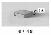
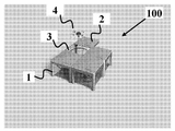
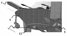
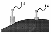
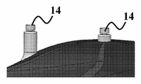
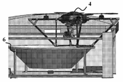
도 1a 및 도 1b는 착륙/이륙 및 저장 목적에 맞는, 현재 사용되고 있는 드론 스케이션들을 예시한다. 그러한 스테이션이 포함하는 주요 구성요소들은 셀 자체(1A), 콘 형상의 착륙/이륙 및 도킹 허브(6A) 및 열고 드론(4A)이 이륙하게 하며 저장을 위해 닫기 위한 슬라이딩 커버(2A)이다.Figures < RTI ID = 0.0 > 1A < / RTI > and 1B illustrate currently used drones stations for landing / takeoff and storage purposes. The main components of such a station are the cell itself 1A, the cone-shaped landing / take-off and
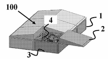
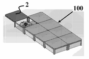
본 발명의 바람직한 개념은 도 2a 내지 도 2e에 예시되며, 여기서 멀티 셀 스테이션(100)의 상이한 구성들이 이웃하는 셀들 및 하나 이상의 착륙/이륙 셀(3)과 공유되는 적어도 두 개의 측을 갖는 서로 인접한 복수의 도킹 셀(1)을 포함한다. 드론들(4)의 거처가 되는 도킹 콘들(6)은 도 2d에 개략적으로 예시되며, 여기서 콘들은 그것들 및 그것들 내부의 드론들(4)을 셀들(1)을 통해 순환시키기 위한 전이 메커니즘 상에 장착된다. 다층 스테이션(100)이 또한 모든 셀(1)에서의 모든 드론(4)을 또는 단지 착륙/이륙 셀(3)이 구비되는 층에서의 드론들을 서비스하는 하나 이상의 착륙/이륙 셀(3)을 도시하는 도 2c 및 도 2b에 예시된다.A preferred concept of the present invention is illustrated in Figures 2A-2E, wherein different configurations of the
하나보다 많은 드론이 요구되는 다양한 적용예, 예를 들어, 보안 적용예들 또는 긴급 적용예들이 있다. 드론을 스테이션(100)에 착륙시킬 때, 뚜껑(2)은 열려야 한다. 이를 위해, 이전에 논의된 바와 같이 스테이션에 드론을 정확하게 착륙시키기 위한 이미지 프로세싱 기술이 제공된다. 현재 기술은 복수의 드론에 대해, 각 드론이 그 자체의 도킹 스테이션을 가능성 있게 필요로 할 수 있는 것이다. 그러나 이는 드론의 이륙 및 착륙에 전용되는 스테이션이 그것을 작용하게 만들기 위해 추가 기술들을 필요로 하기 때문에 비용이 많이 든다. 본 발명의 모듈식 스테이션(100)은 고객을 위해 비용을 낮추기 위해 그러한 상황들에서의 어려움들을 극복한다. 기본적으로, 스테이션(100)은 위에서 논의된 바와 같은 단지 하나의 이륙 및 착륙 셀(3)을 사용하고 그것에 도킹 또는 저장 셀들을 추가하는 것을 가능하게 한다. 이러한 모듈식 솔루션은 도 2e에 예시되고 모든 스테이션 구성이 도 2a 내지 도 2e 및 도 3a 내지 도 3c에 개괄적으로 예시된다. There are various applications where more than one drones are required, for example, security applications or emergency applications. When the drones are landed on the
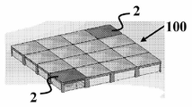
저장 셀들(1)은 착륙/이륙 셀(3)에 부착된다. 그것들이 연결되면, 그것들은 복수의 드론이 도킹되기 위한 보다 큰 스테이션을 생성한다. 드론들은 착륙/이륙 셀(3)에서 단지 착륙 및 이륙만을 하고, 그에 따라 착륙/이륙 셀(3)과 구분되는 기술들이 요구된다. 도킹/저장 셀들(1)은 끌어당김 뚜껑을 필요로 하지 않고 정확한 착륙 기술을 필요로 하지 않으며, 이들 양자는 스테이션에 추가 비용을 추가하는 것이다. 그에 따라, 본 발명은 복수의 드론이 가장 효율적으로 그리고 비용 효율적인 방식으로 사용되게 한다.The
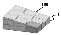
그것이 하나보다 많은 드론을 동시에 론치 또는 수용해야 할지도 모를 경우 복수의 착륙/이륙 셀(3)이 또한 추가될 수도 있다. 도 3a 내지 도 3c는 셀들에서의 드론들을 부분 또는 전부 서비스하는 하나 이상의 착륙/이륙 셀(3)을 갖는 단층 멀티 셀 스테이션(100)의 추가 구성들을 예시한다. 두 개의 대향하는 착륙/이륙 셀(3)을 갖는, 이를테면 도 3b 및 도 3c에 예시된 스테이션의 구성은 두 개의 드론(4)의 동시 론치를 동시에 가능하게 하여, 보다 효율적인 것으로 드러날 수 있다. A plurality of landing / take-
도킹 셀들(1) 상의 벽들(1a), (1b)은 요구될 때 도 6에 예시된 바와 같이 저장 스테이션들을 그것들에 연결하기 위해 제거될 수 있도록 설계된다. 이는 스테이션(100) 내에 개방 공간을 생성하며, 이는 전이 시스템의 스테이션(100) 내 설치 및 작동을 가능하게 한다.The
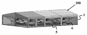
그 다음 도킹/저장 셀들(1)은 용이하게 연결되고 복수의 드론(4)을 저장할 수 있는 큰 스테이션(100)을 생성한다. 추가되는 각 셀(1)은 추가 드론이 스테이션(100)에 도킹될 수 있게 한다. 이를 관련된 솔루션으로 만들기 위한 최소 구성은 네 개의 드론(4)을 홀딩할 수 있는 스테이션을 이루는 하나의 착륙/이륙 셀(3) 및 세 개의 도킹/저장 셀(1)을 갖는 것이다. 이에 대한 이유는 드론들이 그것들이 착륙하는 시간부터 그것들이 이륙하는 시간까지 폐루프 회로를 따를 것이 요구되기 때문이다. 그러나, 폐루프 구성을 유지하는 이러한 솔루션을 위해 구현될 수 있는 복수의 구성이 있다. 많은 양의 드론이 요구된다면, 많은 저장 스테이션이 위에서 논의된 도면들에 예시된 바와 같이 추가될 수 있다. The docking /
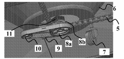
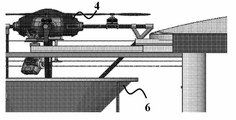
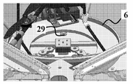
전이 시스템을 보다 상세하게 언급하면, 드론들(4)이 착륙/이륙 스테이션들에 착륙할 때, 그것들은 콘 형상의 디바이스(6)에 착륙한다. 드론(4) 상의 원뿔 모양 다리들(도 7a, 4b)이 셀(3)에서의 콘(6)과 맞아 셀(3)에 있을 때 밀리미터 정밀도를 가능하게 한다. 콘들(6)은 드론들(4)을 셀에서 셀로 전달하는 도 4a 내지 도 4e에서의 체인(5)으로서 예증되는, 전이 시스템에 연결된다. 도킹/저장 셀들(1)이 추가되어 모듈식 스테이션(100)을 만들 때, 드론(4)을 홀딩하기 위해 사용되는 콘(6)은 셀들 간 전이를 돕기 위해 바퀴들(7)을 구비한다. 도 4a 내지 도 4e는 콘들(6)의 전이를 돕기 위해 사용되는 전이 시스템, 예를 들어, 체인(5) 및 바퀴들(7)을 예시한다.Referring to the transition system in more detail, when the
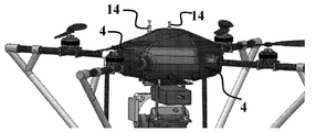
드론이 정확한 착륙하는 것을 돕기 위해 사용되는 원뿔 형상 다리들에 대한 드론들의 다리들(4b)이 도 7a 내지 도 7에 도시된다. 정확한 착륙은 위에서 언급된 바와 같이 이미지 프로세싱으로 이루어지나, 원뿔 형상 다리들은 그것이 착륙하고 있을 때 드론의 스테이션에서의 위치 미세 조정을 돕는다. 다리들(4b)은 또한 드론이 착륙/이륙 스테이션(3)에 착륙될 때 프로펠러들을 보호하는 역할을 하는 프로펠러들의 가장 먼 지점을 지나 연장된다. 다리들(4b)은 45도의 각도로 위치된다. 다리들(4b)의 바닥은 3면 직사각형 형상(4c)을 형성하며 이는 드론이 필요할 경우 스테이션 밖에 착륙하게 하고 또한 유상하중에 대한 최적의 시야를 제공한다.The drones'
드론들의 가장 중요한 특징들 중 몇몇이 아래에서 논의된다. Some of the most important features of the drones are discussed below.
비행 제어기 - 비행 제어기는 드론 상의 가장 중요한 구성요소이다. 비행 제어기는 드론의 "뇌"이다. 그것은 모든 전기적 구성요소에 연결되고 그것들을 전부 드론의 비행을 가능하게 하도록 제어한다. 본 발명은 다양한 비행 제어기와 작동하고 그에 따라 우리의 솔루션을 갖고 다양한 드론을 사용한다. 명백히, 드론의 크기는 상업적 용도들을 위해 드론들을 사용할 때 중요한 요인이다.Flight controller - Flight controller is the most important component on the drones. The flight controller is the "brain" of the drones. It is connected to all electrical components and controls them all to enable the drones to fly. The present invention operates with a variety of flight controllers and thus uses a variety of drones with our solutions. Obviously, the size of the drones is an important factor when using drones for commercial uses.
크기 - 본 발명은 상업적 용도들을 위해 설계되고 그에 따라 연장된 시간의 양 동안 상대적으로 무거운 유상하중(평균 0.5 kg - 3kg)을 운반하기에 충분히 큰 드론들을 사용한다. 현재 사용되고 있는 드론들은 가장자리에서 가장자리까지 미터 길이를 조금 넘는다. 중요한 것은 스테이션들이 크기가 최소이도록 만들어지나 계속해서 드론들이 도킹되기에 충분한 공간을 가능하게 한다는 것이다. 또한 스테이션들은 단지 드론들이 착륙/이륙 스테이션에서 저장 스테이션들로 전이하게 하는 데 딱 적정한 규모이다.Size - The invention is designed for commercial uses and accordingly uses drones that are large enough to carry relatively heavy oil loads (an average of 0.5 kg to 3 kg) during an extended amount of time. The drones currently in use are just over meters long from the edge to the edge. Importantly, the stations are made to be small in size but continue to allow enough space for the drones to be docked. The stations are also just the right size to allow the drones to transition from the landing / take-off station to the storage stations.
도 7a 내지 도 7c는 콘 형상 다리들(4b) 및 드론을 수용하기 위해 사용되는 셀(3) 내 콘(6)을 도시한다. 이러한 도면들은 또한 드론 다리들(4b)이 스테이션의 측 상에 착륙하더라도, 다리들의 각도는 여전히 드론이 콘(6)으로 이동하게 하며 드론들이 셀로 착륙시 편차를 보다 허용되게 한다는 것을 나타낸다.Figs. 7A to 7C show the
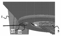
착륙/이륙 셀들(3) 및 저장 셀들(1) 양자의 중심에는, 폐쇄 루프 체인(5)이 감싸지는 상측 부분(8b) 및 축을 중심으로 한 회전을 위해 폐쇄 루프 벨트(9)를 갖고 사이드 바퀴(1)와 연결되는 하측 부분(8a)을 갖는 중앙 톱니 바퀴가 있다. 모터(11)는 체인(5)의 움직임에 따른 콘(6)의 움직임을 보장하기 위해 중심측이 되는 위치에서 일측 상이 드론(6)의 바닥에 그리고 타측 상이 상측 부분(8b) 중앙 톱니 바퀴(8b)에 연결된다. 착륙/이륙 셀(1)에서의 중앙 톱니 바퀴(8a, 8b)는 피니언(pinion)으로서의 역할을 하고 모터가 달려 모든 드론(4)이 셀들의 어레이를 통해 순환하게 만든다. 이는 베터리가 방전된 드론(4)이 스테이션에 진입할 때 일어나고 가장 오래(그리고 그에 따라 배터리가 충전된) 스테이션에 있었던 드론이 이륙하도록 요구된다. 사이드 바퀴(10)는 착륙/이륙 셀(1)에서 그것의 축 주위 중심 톱니바퀴(8a, 8b)의 안정한 축을 중심으로 한 회전을 보장하여 모든 콘(6)이 그것들 내 드론들(4)과 회전하고 셀을 그것들이 바로 있었던 셀 다음 셀로 이동하게 만든다.. 이는 도 4a 내지 도 4e에서 전이 시스템을 추진하는 착륙/이륙 스테이션에서의 기어 및 모터에 예시된다.At the center of both the landing / take-
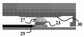
도 5a 내지 도 5l에 더 상세하게 예시되고 예증될 바와 같이 드론들이 스테이션에 있을 때 그것들의 재충전을 위해 필요한 전기 접촉부들을 갖는다. 모든 전기 접촉부는 드론의 회전과 무관하게 접촉을 보장하기 위해 원형이다. 도 4b는 이전에 논의되었던 콘(6)의 바닥의 접촉부(12)를 도시한다. 도 4c는 콘(6)에서의 접촉부(12)에 연결되는 콘(6) 아래에 있는 접촉부(13)를 도시한다. 재충전 방법은 착륙/이륙 셀에서와 동일한 방법으로 작용한다. 모든 도킹/저장 셀(1)은 착륙/이륙 셀(3)의 전자장치들에 연결되며, 그에 따라 셀들의 전체 어레이에 대해 단지 하나의 충전기 및 전기 회로가 요구된다. 자율 재충전을 가능하게 하기 위해, 네 개의 연결부로 전기 회로를 닫는 것이 요구된다. 두 개의 연결은 원뿔 형상 디바이스(6)로부터 드론(6)과 접촉하게 되고 둘은 셀의 지붕으로부터 끌어당김 디바이스(도 5c 내지 도 5e에서의 28)로부터 접촉하게 된다. 도 5c는 충전 패드(15) 및 끌어당김 디바이스(28)를 예시한다. 각 도킹/저장 셀(1)은 또한 이러한 유닛을 구비하고 드론들(4)이 도킹/저장 셀(1)로 이동될 때 접촉부들이 충전을 위해 재연결된다.As shown and illustrated in more detail in Figures 5A-51L, the drones have electrical contacts necessary for their recharging when in the station. All electrical contacts are circular to ensure contact regardless of the rotation of the drones. 4B shows the
끌어당김 디바이스(28)는 드론 위 포고 핀들(14)과 연결하기 위해 그것의 바닥면의 끌어당김 디바이스 접촉부들(15a)을 운반하는 하측 원형 패드(15)를 포함한다. 패드(15)는 직사각형 중공 프레임(19), 중공 프레임(19) 내 나사(16) 및 너트(18), 나사(16) 상에 장착되고 나사(16)의 수직 모션의 연장을 프레임(19)의 상부로 제한하는 상부 스토퍼(20) 및 재충전을 위해 회로를 닫기 위해 끌어당김 디바이스(28)를 하강 및 상승시키기 위한 리드 나사에 모터(32) 위를 연결하는 연결기(17)를 포함하는 수직 하강 어셈블리로 홀딩된다. 도 5d는 드론의 상부 상의 포고 핀들(14)과 맞는 접촉부들(15a)을 갖는 하측 패드(15)를 도시하는 끌어당김 디바이스(28)의 보다 면밀한 모습을 예시한다. 도 5f 및 도 5g는 각각, 패드(5)와 분리 및 연결 상태들의 핀들(15)을 도시한다. 도 5a 및 도 5b는 각각, 콘(6) 내 정착된 위치에 있는 드론(4) 및 두 개의 전기 접촉부를 폐쇄하기 위해 드론의 상부 상의 두 개의 포고 핀(14)을 갖는 드론(4)을 도시한다. 도 5e는 회로를 드론의 상부 쪽으로 하강시키고 패드(15) 포고 핀들(14)로 폐쇄하기 위한 끌어당김 디바이스(28)를 도시한다.The
각 도킹/저장 셀(1)은 콘(6)의 바닥에서의 접촉 핀(27)에 연결되는 핀(도 5l에서의 29)을 갖는다. 핀(27)은 밀어 붙여져 스프링 장전(23)되며, 이는 드론의 사선 다리들 및 측면 프레임을 홀딩하는 조인트(22)의 바닥 상의 접촉부(도 5i 내지 도 5l에서의 30)로 회로를 폐쇄하는 것을 가능하게 한다. 이는 이전에 언급된 바와 같이 재충전을 위해 회로를 폐쇄하기 위해 바닥의 두 개의 접촉부를 폐쇄한다. 이러한 솔루션은 바닥 접촉부(30)가 도킹/저장 셀(1)에 있을 때 착륙/이륙 셀(3)의 전자장치들에 연결되는 것을 가능하게 한다. Each docking / storing
도킹/저장 셀들(1)이 착륙/이륙 셀(3)에 연결될 때 드론이 도킹/저장 셀(1)에 있을 때 도킹/저장 셀들(1)이 드론(4)의 배터리들을 재충전시키는 것을 가능하게 하는 전기 접촉부들이 있다. 도킹 저장 셀들(1)을 착륙/이륙 셀(3)에서의 전기 회로에 연결함으로써, 비용이 이전보다 한층 삭감되고 도킹 저장 셀들(1)에 있을 때에도 계속해서 충전을 가능하게 하기 위한 빠르고 간단한 방식을 가능하게 한다.It is possible to allow the docking /
위에서 상세하게 설명된 바와 같이, 본 발명은 드론이 스테이션에 착륙되었을 때 자율 충전을 관리하는 온-보드 회로를 제공한다. 현재 사용되고 있는 드론들은 6-셀 배터리들을 갖는다. 그것들을 적절하게 충전하기 위해, 그것들은 균형 맞춰 충전될 필요가 있다, 즉 모든 셀이 동일한 속도로 충전될 필요가 있다. 이는 모든 셀이 함께 충전되고 균형이 맞춰짐을 확실히 하기 위해 배터리의 플러스 및 마이너스 및 추가 7개의 리드가 충전기에 연결함으로써 이루어진다. 본 발명은 자율 충전을 필요로 하기 때문에 충전을 가능하게 하기 위해 폐쇄되어야 하는 회로들의 양은 최소이어야 한다.As described in detail above, the present invention provides an on-board circuit for managing autonomous charging when the drones land on the station. Currently used drones have 6-cell batteries. To properly charge them, they need to be charged in balance, that is, all cells need to be charged at the same rate. This is done by connecting the plus and minus of the battery plus an additional 7 leads to the charger to ensure that all the cells are charged together and balanced. Since the present invention requires autonomous charging, the amount of circuits that must be closed to enable charging must be minimal.
이를 위해, 드론은 드론 상에 안착하는 온-보드 회로를 포함하고 배터리의 충전 균형을 관리한다. 이는 다른 7개의 리드가 아닌 단지 배터리의 플러스 및 마이너스를 연결하는 것을 가능하게 한다. 충전하기 이전에 드론이 턴 오프되는 것이 중요하고 그에 따라 온-보드 회로는 마이크로컨트롤러(마이크로컨트롤러는 스테이션에서 "뇌"이다)에 연결되는 두 개의 추가 전기 리드를 갖고 마이크로컨트롤러가 드론 턴 오프 신호를 제공할 때 충전을 위해 충전기에 연결된다.To this end, the drones include an on-board circuit that rests on the drones and manages the charge balance of the battery. This makes it possible to connect the plus and minus of the battery, not just the other seven leads. It is important that the drones are turned off before charging, so that the on-board circuit has two additional electrical leads connected to the microcontroller (the microcontroller is the "brain" in the station) and the microcontroller sends the dron- When supplied, it is connected to the charger for charging.
도 8은 재충전을 위한 전기 회로들의 상이한 구성요소들로 회로들을 폐쇄하는 다음 접촉 기능들을 갖는 온-보드 전기 회로를 제시한다:8 presents an on-board electrical circuit having the following contact functions for closing the circuits with the different components of the electrical circuits for recharging:
회로는 그것 상에 네 개의 플러그를 갖는다. The circuit has four plugs on it.
1. 배터리 플러그. 1. Battery plug.
a. 배터리는 이러한 플러그에 직접 연결된다. a. The battery is connected directly to these plugs.
2. 드론 플러그. 2. Drone plug.
a. 이러한 플러그는 드론에 연결되고 배터리가 배터리 플러그에 연결될 때 드론에 전력을 제공한다. a. These plugs connect to the drones and provide power to the drones when the batteries are plugged into the battery plug.
3. 충전기 플러그. 3. Charger plug.
a. 이러한 플러그는 드론 상의 두 개의 포고 핀(14)에 연결되고 이러한 상태에 있을 때 충전판들(15)과 접촉하게 된다. a. These plugs are connected to two pogo pins 14 on the drone and in contact with the charging
4. 신호 플러그. 4. Signal plug.
a. 이러한 플러그는 또한 두 개의 포고 핀(14)에 연결되고 셀에서의 두 개의 판(접촉부(15a)를 통한 15)과 접촉하게 된다. 이러한 판들은 마이크로컨트롤러에 연결되고 마이크로컨트롤러 상의 신호가 너무 낮아질 때 회로 상의 트랜지스터가 그것의 기능을 전환하고 드론 플러그를 "분리"하며 충전 플러그를 "연결"하고 드론이 턴 오프되게 그리고 배터리가 재충전되게 한다. a. This plug is also connected to two
하나의 특정한 실시예에서, 드론들에 사용되는 배터리들은 몇몇 셀로 나눠지는 리튬 폴리머 배터리이다. 드론의 크기에 따라, 상이한 양들의 셀들을 갖는 상이한 배터리들이 사용된다. 현재 사용되고 있는 드론들은 6-셀 리튬 폴리머(또는 리포) 배터리와 작동한다. 본 발명의 재충전 시스템은 모든 유형의 리포 배터리와 작용하고 6-셀 배터리들로만 제한되지 않는다.In one particular embodiment, the batteries used in the drones are lithium polymer batteries divided into several cells. Depending on the size of the drones, different batteries with different amounts of cells are used. The currently used drones work with a 6-cell lithium polymer (or lipo) battery. The recharge system of the present invention works with all types of rechargeable batteries and is not limited to 6-cell batteries.
도킹 스테이션은 마이크로컨트롤러 및 인터넷 연결을 위해 사용되는 통신 디바이스로 제어된다. 마이크로컨트롤러는 다음을 포함하여 스테이션을 실행하는 모든 물리적 요소를 관리한다:The docking station is controlled by a microcontroller and a communication device used for the Internet connection. The microcontroller manages all the physical elements that run the station, including:
· 뚜껑을 개/폐하기 위해 모터에 전력을 제공 · Providing power to the motor to open / close the lid
· 마이크로 스위치들에 연결하는 것은 모터를 중단해야 할 때를 결정 · Connecting to micro-switches determines when the motor should be stopped
· 폐쇄될 때 뚜껑을 잠그기 위해 솔레노이드에 연결됨 · Connected to the solenoid to lock the lid when closed.
· 정확한 착륙을 위해 비콘에 연결됨 Connected to beacon for accurate landing
· 충전 패드를 위해 다른 모터에 연결됨 Connected to another motor for charging pad
· 배터리 재충전을 위해 충전기에 연결됨 · Connected to charger for battery recharging
· 충전 전 그것을 턴 오프하고 이륙 전 그것을 턴 온하기 위해 드론에 연결됨 · Connected to the drones to turn it off before charging and turn it on before takeoff
스테이션은 다수의 방식; 벽 콘센트, 카 잭, 또는 다른 전원들에 의해 전력을 공급받을 수 있다. 예를 들어 스테이션이 전통적인 전력 공급원들이 이용가능하지 않은 영역에 위치되는 경우, 스테이션은 다른 수단들; 예를 들어 지붕에 부착되거나 스테이션 부근에 위치되는 솔라 패널에 의해 충전될 수 있다. 도 9는 셀(1) 위의 솔라/광전지 패널(24)을 사용하는 솔라 또는 광전지 셀 충전 충전기를 예시한다. 이는 특히 고립되거나 떨어져 있는 서비스 영역들에 스테이션을 구성 및 설치할 때 효율적이다. 이렇게 하여 어떠한 전력선도 그러한 장소들에 연장되지 않아야 하며, 스테이션의 충전기의 직접 재충전을 위해 태양 방사를 이용한다.The station may be in a number of ways; It can be powered by wall outlets, car jacks, or other power sources. For example, if a station is located in an area where traditional power supplies are not available, the station may be able to use other means; For example, by a solar panel that is attached to the roof or located near the station. Figure 9 illustrates a solar or photovoltaic cell filler charger using solar /
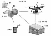
도 10은 클라우드 서버 플랫폼에 기반한 원격 제어, 감독 및 데이터 저장 시스템을 예시한다. 일반적으로, 드론들은 RF 또는 라디오 주파수에 의해 전력을 공급받는다. RF는 몇몇 킬로미터의 범위로 제한된다. 본 발명은 셀룰러 연결을 통해 드론들을 제어하기 위한 방법을 제공한다. 셀룰러 연결을 사용하는 이점들은 드론이 비행하여 도착할 범위에 의해 제한되지 않는다는 것 뿐만 아니라, 우리의 클라우드 기반 서버(26)가 드론(4)과 일정한 통신을 하게 한다는 것을 포함한다. 서버(26)가 드론에 연결되기 때문에, 원격 사용자(31)가 지속적으로 드론(4)의 상태가 어떠한지를 정확하게 안다. 그에 따라, 본 발명은 드론이 스테이션(100)에서 얼마나 떨어져 있는지, 드론이 얼마나 많은 전력을 소모하고 있는지, 미션을 인계받기 위해 새로운 드론을 언제 보내야 할지 그리고 드론들을 언제 다시 기지로 보내야 할지를 지속적으로 계산하는 대응하는 알고리즘들을 포함한다.Figure 10 illustrates a remote control, supervisory and data storage system based on a cloud server platform. Generally, drones are powered by RF or radio frequencies. RF is limited to a range of several kilometers. The present invention provides a method for controlling drones via a cellular connection. Advantages of using a cellular connection include not only that the drones are limited by the range to which they will fly, but also that our cloud-based
스테이션(100)은 또한 클라우드 서버(26)에 연결되며, 이는 드론들(4)의 충전 상태, 스테이션 내 그리고 외부의 날씨 상황에 관한 데이터를 수신하게 하고 스테이션(100) 및 드론을 원격에서 제어하는 것을 가능하게 한다.The
데이터 다운로드 - 상업 용드들로 드론을 사용하는 것의 주요 목적들은 데이터를 수집하는 것이다. 드론은 일반적으로 유상하중 및 카메라를 운반하고 카메라는 데이터를 수집한다. 드론이 스테이션에 착륙하면, 데이터는 클라우드 서버(26)에 전달되고 고객에게 전달된다. 고객은 그것이 모두 온라인이기 때문에 데이터를 수신하기 위해 스테이션(100) 및 드론(4) 근처 어딘가에 있을 필요가 없다. Downloading Data - The main purpose of using drone as a commercial player is to collect data. Drones typically carry heavily loaded and cameras and the camera collects data. When the drones land on the station, the data is delivered to the
미션 업로드 - 드론은 미션이 그것에 업로드되는 경우 자율적으로 단지 비행할 수 있다. 많은 상업 용도는 수 비행 시간을 필요로 하고 그에 따라 별개의 미션들이 각 개별적인 비행마다 업로드될 것을 필요로 한다. 본 발명은 이러한 이슈를 또한, 가능성 있게 몇 시간 걸릴 수 있는 미션의 고객 업로드에 의해, 해결한다. 본 발명의 소프트웨어는 미션을 서브 미션들로 나누고 각 비행 전 드론에 적절한 미션을 보내도록 구성된다.Mission Upload - A dron can autonomously fly only if a mission is uploaded to it. Many commercial applications require number of flight times and thus require that separate missions be uploaded for each individual flight. The present invention solves this issue also by customer uploading of the mission, which may possibly take several hours. The software of the present invention is configured to divide the mission into submissions and to send appropriate missions to each pre-flight drones.
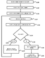
도 11은 어플리케이션의 소프트웨어가 단계들 (1100) 내지 (1150)로 어떻게 스테이션을 제어 및 관리하는지를 상세하게 설명한다.11 illustrates in detail how the software of the application controls and manages the stations in
이러한 기술이 유용할 수 있는 어플리케이션의 예는 주요한 정보를 정확한 농업을 필요로 하는 농장주들에게 제공하기 위해 농장을 스캐닝하는 것을 위한 것이다.An example of an application where such a technique may be useful is for scanning farms to provide farmers with the necessary information with accurate agriculture.
예를 들어, 스테이션(들)은 농장주의 헛간의 지붕 또는 임의의 원하는 다른 장소 상에 설치될 수 있다. 스테이션은 그것이 방수라는 사실에 기인하여 해당 장소에서 연중 계속되게 유지될 수 있다. 농장주가 그의 논밭이 스캔되기 원할 때, 그는 드론(들)을 전화 또는 컴퓨터 어플리케이션으로 보낼 수 있거나 그는 드론(들) 지정된 시간마다(예를 들어, 하루에 한 번, 일주일에 두 번, 일주일에 다섯 번 등) 그의 논밭을 스캔도록 미리 프로그램되게 할 수 있다. 농업을 위해 지정된 소프트웨어를 이용하여, 논밭은 드론이 배터리가 가능하게 하는 기간에 걸쳐 이어질 수 있는 섹션들로 나눠지도록 미리 프로그램될 수 있다. 제1 섹션이 스캔 완료되고 배터리가 부족하면, 드론은 배터리 재충전 또는 교환하기 위해 자율적으로 스테이션으로 귀환 비행할 수 있다. 드론이 완충된 배터리를 가지면, 그것은 논밭의 다음 섹션을 스캔하기 위해 다시 스테이션을 떠날 수 있다. 이러한 프로세스는 전체 필드가 스캔될 때까지 이루어질 수 있다. 지정된 카메라가 드론에 부착될 수 있고 요구되는 구체적인 정보를 농장주에게 제공할 수 있다. 미션의 마지막에, 수집된 정보는 농장주의 이메일 또는 전화 어플리케이션 또는 다른 디바이스에 자동으로 보내질 수 있다. 도킹 스테이션 솔루션은 농장주가 이러한 결정적인 정보를 그가 그것을 필요로 할 때 어떠한 사람의 개입도 없이 수신하게 한다.For example, the station (s) may be installed on the roof of the shed or on any other desired location. A station can be kept year-round at the location due to the fact that it is waterproof. When the farmer wants his field to be scanned, he can send the drone (s) to a telephone or computer application, or he can send it to the drone (s) at designated times Etc.) can be pre-programmed to scan his field. Using the software designated for agriculture, the fields can be preprogrammed to be divided into sections that can last throughout the period that the drones are battery-enabled. If the first section has been scanned and the battery is low, the dron can autonomously fly back to the station to recharge or replace the battery. If the drones have a fully charged battery, it can leave the station again to scan the next section of the field. This process can be performed until the entire field is scanned. A designated camera can be attached to the drones and provide the farmer with the specific information required. At the end of the mission, the collected information can be automatically sent to the farmer's e-mail or phone application or other device. The docking station solution allows the farmer to receive this crucial information when he needs it without any human intervention.
Claims (18)
하나 이상의 착륙/이륙 셀;
적어도 두 개의 도킹/저장 셀;
상기 착륙/이륙 셀들 및 도킹/저장 셀들 내에서 상기 드론들을 수송하도록 구성된 전이 폐쇄 루프 시스템(closed-loop system); 및
상기 멀티 셀 스테이션의 자율 제어, 작동 및 관리를 위해 구성된 제어 수단을 포함하되,
상기 하나 이상의 착륙/이륙 셀 및 적어도 두 개의 도킹/저장 셀의 각각은 이웃하는 셀들과 적어도 두 측을 공유하는, 멀티 셀 스테이션.As a multi-cell station for drones,
One or more landing / takeoff cells;
At least two docking / storing cells;
A closed-loop system configured to transport the drones within the landing / take-off cells and docking / storing cells; And
And control means configured for autonomous control, operation and management of the multi-cell station,
Wherein each of said at least one landing / takeoff cell and at least two docking / storage cells share at least two sides with neighboring cells.
상기 드론들 위의 두 개의 상측 스프링 장전 포고 핀(pogo pin) 접촉부;
상기 드론들의 다리들의 말단부들에서의 두 개의 하측 스프링 장전 포고 핀 접촉부;
상기 착륙/이륙 셀 및 도킹/저장 셀의 커버의 내측 상의 상부 끌어당김 디바이스; 및
상기 착륙/이륙 셀 및 도킹/저장 셀 내에 거꾸로 위치되는 콘의 바닥에서의 접촉부를 포함하되,
상기 드론 위 상기 스프링 장전 포고 핀 및 끌어당김 디바이스가 회로를 폐쇄하도록 구성되고,
상기 드론의 하측 단부에서의 상기 스프링 장전 포고 핀 접촉부들 및 상기 콘의 바닥에서의 접촉부들이 회로를 폐쇄하도록 구성되는, 멀티 셀 스테이션.3. The apparatus of claim 2, wherein the recharging means comprises:
Two upper spring loaded pogo pin contacts on said drones;
Two lower spring loaded pogo pin contact portions at the ends of the legs of the drones;
An upper pull device on the inside of the cover of the landing / takeoff cell and the docking / storing cell; And
A landing / takeoff cell and a contact at the bottom of the cone placed upside down in the docking / storage cell,
The spring loaded pogo pin on the dragon and the pull device are configured to close the circuit,
Wherein the spring loaded pogo pin contacts at the lower end of the drones and contacts at the bottom of the cone are configured to close the circuit.
폐쇄 루프 궤도 체인;
중앙 톱니 바퀴;
사이드 톱니 바퀴;
폐쇄 루프 벨트; 및
모터를 포함하되,
상기 폐쇄 루프 궤도 체인은 상기 중앙 톱니 바퀴를 감싸고, 상기 중앙 톱니 바퀴는 상기 모터와 축 방향으로 연통하고, 상기 모터는 콘의 바닥과 축 방향으로 연통하며, 상기 콘은 뒤집힌 상태로 구성되어 상기 드론의 거처가 되며,
상기 폐쇄 루프 벨트는 상기 톱니 바퀴 및 상기 사이드 바퀴의 바닥을 감싸는, 멀티 셀 스테이션.6. The orbiting chain according to claim 5,
Closed loop orbital chain;
Center gear;
Side gear;
Closed loop belts; And
Comprising a motor,
Wherein said closed loop raceway chain surrounds said central toothed wheel, said central toothed wheel communicates axially with said motor, said motor communicates axially with a bottom of the cone, said cone being in an inverted state, And,
Wherein the closed loop belt surrounds the bottom of the cog wheel and the side wheel.
Applications Claiming Priority (3)
| Application Number | Priority Date | Filing Date | Title |
|---|---|---|---|
| US201562270230P | 2015-12-21 | 2015-12-21 | |
| US62/270,230 | 2015-12-21 | ||
| PCT/IL2016/051362 WO2017109780A1 (en) | 2015-12-21 | 2016-12-21 | Autonomous docking station for drones |
Publications (1)
| Publication Number | Publication Date |
|---|---|
| KR20180098293A true KR20180098293A (en) | 2018-09-03 |
Family
ID=59090256
Family Applications (1)
| Application Number | Title | Priority Date | Filing Date |
|---|---|---|---|
| KR1020187019750A Withdrawn KR20180098293A (en) | 2015-12-21 | 2016-12-21 | Autonomous docking station for drones |
Country Status (8)
| Country | Link |
|---|---|
| US (1) | US20190002127A1 (en) |
| EP (1) | EP3393911A4 (en) |
| JP (1) | JP2019502594A (en) |
| KR (1) | KR20180098293A (en) |
| CN (1) | CN108367813A (en) |
| AU (1) | AU2016376213A1 (en) |
| IL (1) | IL260190B (en) |
| WO (1) | WO2017109780A1 (en) |
Cited By (1)
| Publication number | Priority date | Publication date | Assignee | Title |
|---|---|---|---|---|
| KR102195933B1 (en) | 2020-09-10 | 2020-12-29 | 황건호 | Docking apparatus for drone |
Families Citing this family (76)
| Publication number | Priority date | Publication date | Assignee | Title |
|---|---|---|---|---|
| IL237130A0 (en) * | 2015-02-05 | 2015-11-30 | Ran Krauss | Landing and charging system for drones |
| WO2016172829A1 (en) * | 2015-04-27 | 2016-11-03 | 深圳市大疆创新科技有限公司 | Sliding door assembly and ground base station using same |
| IL257520B (en) * | 2015-08-17 | 2022-08-01 | H3 Dynamics Holdings Pte Ltd | Drone box |
| US11065976B2 (en) * | 2016-02-24 | 2021-07-20 | Archon Technologies S.R.L. | Docking and recharging station for unmanned aerial vehicles capable of ground movement |
| CN114245020A (en) * | 2016-08-04 | 2022-03-25 | 深圳市大疆创新科技有限公司 | Method and system for processing image data |
| JP6371959B2 (en) * | 2016-09-02 | 2018-08-15 | 株式会社プロドローン | Robot arm and unmanned aircraft equipped with the same |
| US10934019B2 (en) * | 2016-11-29 | 2021-03-02 | Easy Aerial Inc. | Unmanned aerial vehicle charging station with centering mechanism |
| EP3655324B1 (en) * | 2017-07-21 | 2025-07-23 | Sentien Robotics, Inc. | Uav retrieval and deployment system |
| WO2019023111A1 (en) * | 2017-07-24 | 2019-01-31 | Walmart Apollo, Llc | Wireless charging and protection for unmanned delivery aerial vehicles |
| CN109383799A (en) * | 2017-08-07 | 2019-02-26 | 菜鸟智能物流控股有限公司 | Aircraft charging method and related device |
| US10495421B2 (en) * | 2017-08-25 | 2019-12-03 | Aurora Flight Sciences Corporation | Aerial vehicle interception system |
| US10526094B2 (en) | 2017-09-29 | 2020-01-07 | Coretronic Intelligent Robotics Corporation | Platform |
| GB201717137D0 (en) * | 2017-10-18 | 2017-12-06 | Haybeesee Ltd | Device for remote monitoring and activity |
| JP6748049B2 (en) * | 2017-10-18 | 2020-08-26 | 日本電信電話株式会社 | Base station device and wireless communication system |
| CN107645192B (en) * | 2017-10-26 | 2023-12-19 | 东北林业大学 | A fully automatic charging device for drones |
| CN108105550A (en) * | 2017-12-19 | 2018-06-01 | 中国长光卫星技术有限公司 | A kind of sweep type photogrammetric apparatus for eliminating backlash |
| JP2019122110A (en) * | 2017-12-28 | 2019-07-22 | 株式会社ダイヘン | Non-contact power supply device and non-contact power supply method |
| US20190220032A1 (en) * | 2018-01-18 | 2019-07-18 | Eliport, Inc. | Autonomous delivery system with autonomous delivery vehicles and dedicated delivery receiving stations |
| KR20200118143A (en) * | 2018-02-05 | 2020-10-14 | 에이치3 다이나믹스 홀딩스 피티이 엘티디 | Landing platform with improved charging for unmanned vehicles |
| US11813950B2 (en) * | 2018-02-28 | 2023-11-14 | Walmart Apollo, Llc | System for storing unmanned aerial vehicles |
| CN110389603B (en) | 2018-04-16 | 2021-04-09 | 中光电智能机器人股份有限公司 | Temperature control equipment |
| US11453513B2 (en) * | 2018-04-26 | 2022-09-27 | Skydio, Inc. | Autonomous aerial vehicle hardware configuration |
| KR102056909B1 (en) * | 2018-06-12 | 2019-12-17 | (주)인스페이스 | System for operating fully-automated unmanned drone and method thereof |
| US10850840B2 (en) | 2018-06-14 | 2020-12-01 | Florida Power & Light Company | Drone and rover preplacement for remote autonomous inspection of utility system components |
| US11898368B2 (en) | 2018-06-14 | 2024-02-13 | Wing Aviation Llc | Unmanned aerial vehicle housing including deployable landing pads |
| US11099557B2 (en) * | 2018-07-08 | 2021-08-24 | Eric Hanscom | Method of remotely obtaining drone footage |
| CN110745252B (en) * | 2018-07-23 | 2024-11-12 | 上海峰飞航空科技有限公司 | Landing platform, method and charging system for unmanned aerial vehicle |
| JP2020023210A (en) * | 2018-08-06 | 2020-02-13 | 株式会社カーメイト | Unmanned aircraft standby booth |
| CN109050958A (en) * | 2018-08-29 | 2018-12-21 | 深圳市旭发智能科技有限公司 | A kind of unmanned plane continuation of the journey base station |
| WO2020051791A1 (en) * | 2018-09-12 | 2020-03-19 | 深圳市大疆创新科技有限公司 | Base station, control method for unmanned aerial vehicle, and unmanned aerial vehicle system |
| CN109278994B (en) * | 2018-10-18 | 2024-05-03 | 南京寻翼文化传媒有限公司 | A drone with a performance formation LED strobe light |
| JP7217894B2 (en) * | 2018-11-27 | 2023-02-06 | 株式会社ナイルワークス | Work planning device, work planning device control method, control program therefor, and drone |
| WO2020144691A1 (en) * | 2019-01-10 | 2020-07-16 | Spear U.A.V Ltd. | Unmanned aerial vehicle capsule |
| US11124316B2 (en) * | 2019-03-19 | 2021-09-21 | Wing Aviation Llc | Detecting impending motor failure using audio data |
| EP3783586B1 (en) * | 2019-03-26 | 2025-11-19 | Rakuten Group, Inc. | Landing management device, landing management method, and landing management system |
| DE102019109127B4 (en) * | 2019-04-08 | 2023-09-21 | Thomas Weimer | Drone-based aerial and collision monitoring system |
| US11691761B2 (en) * | 2019-05-17 | 2023-07-04 | FlyFocus Sp. z.o.o. | Detachable power cable for unmanned aerial vehicle |
| US11636771B2 (en) | 2019-09-08 | 2023-04-25 | Deere & Company | Stackable housing containers and related systems |
| CN110667870B (en) * | 2019-10-12 | 2023-01-20 | 内蒙古工业大学 | Unmanned aerial vehicle is energy autonomous base station of independently taking off and land trading battery based on solar energy power supply |
| US20210107684A1 (en) * | 2019-10-14 | 2021-04-15 | Olivier Le Lann | Modular autonomous aircraft control and resupply station |
| US11414209B2 (en) * | 2019-12-10 | 2022-08-16 | Dennis Bragg | Mobile launch pad for facilitating launching and landing of flying taxis |
| KR102324340B1 (en) * | 2019-12-24 | 2021-11-11 | 장백산 | Drone apparatus for landing at drone station and method therefor |
| US20210269174A1 (en) * | 2020-02-27 | 2021-09-02 | Greg Douglas Shuff | Drone docking port and method of use |
| CN111392054B (en) * | 2020-03-31 | 2021-12-28 | 广州中科云图智能科技有限公司 | Unmanned aerial vehicle machine nest |
| CA3191056A1 (en) * | 2020-05-18 | 2021-11-25 | Chirag Shah | Method and system to ascertain location of drone box for landing and charging drones |
| US12151829B2 (en) * | 2020-08-06 | 2024-11-26 | Overair, Inc. | Efficient turnaround system for aircraft |
| JP2022041829A (en) * | 2020-08-31 | 2022-03-11 | 株式会社LAplust | Information processing device, information processing system, information processing method, and program |
| CN112073612B (en) * | 2020-09-08 | 2021-11-23 | 曾志长 | Wisdom scenic spot monitored control system convenient to installation |
| CN116348379A (en) * | 2020-09-16 | 2023-06-27 | 德潘徳恩特无人机独立系统有限责任公司 | Logistics station for drones |
| US11440679B2 (en) | 2020-10-27 | 2022-09-13 | Cowden Technologies, Inc. | Drone docking station and docking module |
| US11673690B2 (en) | 2021-01-22 | 2023-06-13 | Easy Aerial Inc. | Modular collapsible and portable drone in a box |
| JP7608252B2 (en) * | 2021-04-15 | 2025-01-06 | Ihi運搬機械株式会社 | Expandable storage port |
| CN113085614A (en) * | 2021-04-16 | 2021-07-09 | 合肥革绿信息科技有限公司 | Unmanned aerial vehicle automatic charging pile for traffic management and use method thereof |
| CN116490429A (en) * | 2021-06-30 | 2023-07-25 | 深圳市大疆创新科技有限公司 | Takeoff and landing platform, unmanned aerial vehicle, takeoff and landing system, storage device and takeoff and landing control method |
| KR102583405B1 (en) * | 2021-07-05 | 2023-09-27 | 주식회사 아르고스다인 | Drone Station |
| CN113247289B (en) * | 2021-07-08 | 2021-10-22 | 西安羚控电子科技有限公司 | Automatic recovery of VTOL fixed wing unmanned aerial vehicle machine nest that charges |
| CN114013674B (en) * | 2021-11-05 | 2024-05-14 | 北京理工大学 | Unmanned aerial vehicle automatic take-off and landing system and unmanned aerial vehicle automatic take-off and landing method |
| CN114228548B (en) * | 2021-12-26 | 2022-11-08 | 枣庄易飞航天科技有限公司 | Large-capacity and large-current composite wing unmanned aerial vehicle charging platform and system |
| KR20230108865A (en) * | 2022-01-12 | 2023-07-19 | 현대자동차주식회사 | Drone docking station and control method thereof |
| DE102022103088A1 (en) | 2022-02-10 | 2023-08-10 | Leon Dederke | Stationary drone box |
| US20230257139A1 (en) * | 2022-02-17 | 2023-08-17 | Airscort, Ltd. | Products, Systems, and Methods for an Autonomous Drone Docking Station |
| CN114559833B (en) * | 2022-03-29 | 2024-01-26 | 南方电网电力科技股份有限公司 | An automatic charging hangar, system and inspection method for drones |
| CN114524105B (en) * | 2022-04-24 | 2022-08-02 | 天津航天中为数据系统科技有限公司 | Unmanned aerial vehicle dynamic take-off and landing device and take-off and landing method |
| US12030399B2 (en) | 2022-04-27 | 2024-07-09 | Skydio, Inc. | Base stations for unmanned aerial vehicles (UAVs) |
| JP2025119070A (en) * | 2022-05-23 | 2025-08-14 | 日立建機株式会社 | Work machinery |
| DE102022115285A1 (en) | 2022-06-20 | 2023-12-21 | E.ON Digital Technology GmbH | Station network for autonomous and/or semi-autonomous unmanned aircraft and methods for controlling autonomous or semi-autonomous unmanned aircraft |
| US11794922B1 (en) * | 2022-08-04 | 2023-10-24 | Wing Aviation Llc | Mobile UAV nest |
| US11764725B1 (en) * | 2022-08-13 | 2023-09-19 | Yonghua Wang | Foldable portable load distributed dual axes lightweight solar tracker |
| FR3141449A1 (en) * | 2022-10-26 | 2024-05-03 | intelligent design | Device for the preservation of glaciers |
| WO2024118965A1 (en) * | 2022-12-01 | 2024-06-06 | Johnson Kara E | Aircraft takeoff and landing apparatus |
| US11655057B1 (en) * | 2022-12-22 | 2023-05-23 | The Adt Security Corporation | Mounts for unmanned aerial vehicles |
| USD1032432S1 (en) * | 2023-01-04 | 2024-06-25 | Autel Robotics Co., Ltd. | Storage unit for unmanned aerial vehicles |
| US12565345B1 (en) | 2023-05-28 | 2026-03-03 | Antonio Liska | Automated drone storage and launch apparatus, system, and method |
| KR102611808B1 (en) * | 2023-06-29 | 2023-12-08 | (주)위플로 | Station apparatus for aircraft capable of checking the drive system |
| AU2024290621A1 (en) * | 2023-07-06 | 2025-12-11 | Pavel Ruslanovich Andreev | System and method for moving payload |
| KR102678862B1 (en) * | 2023-09-26 | 2024-06-28 | 주식회사 위즈윙 | Drone station |
Family Cites Families (23)
| Publication number | Priority date | Publication date | Assignee | Title |
|---|---|---|---|---|
| JP2006001485A (en) * | 2004-06-21 | 2006-01-05 | Yanmar Co Ltd | Unmanned helicopter monitoring device |
| US20060249622A1 (en) * | 2005-05-04 | 2006-11-09 | Lockheed Martin Corporation | Autonomous Environmental Control System and Method For Post-Capture and Pre-Launch Management of an Unmanned Air Vehicle |
| US7581702B2 (en) * | 2006-06-09 | 2009-09-01 | Insitu, Inc. | Wirelessly controlling unmanned aircraft and accessing associated surveillance data |
| US20090314883A1 (en) * | 2007-05-10 | 2009-12-24 | Arlton Paul E | Uav launch and recovery system |
| KR101262968B1 (en) * | 2009-09-02 | 2013-05-09 | 부산대학교 산학협력단 | Unmanned Aerial System Including Unmanned Aerial Vehicle Having Spherical Loading Portion And Unmanned Ground Vehicle Therefor |
| US8511606B1 (en) * | 2009-12-09 | 2013-08-20 | The Boeing Company | Unmanned aerial vehicle base station |
| US8899903B1 (en) * | 2010-05-18 | 2014-12-02 | The Boeing Company | Vehicle base station |
| US8439301B1 (en) * | 2011-07-18 | 2013-05-14 | Systems Engineering Associates Corporation | Systems and methods for deployment and operation of unmanned aerial vehicles |
| JP6180765B2 (en) * | 2012-03-29 | 2017-08-16 | ザ・ボーイング・カンパニーThe Boeing Company | Transportation base station |
| CN103010070B (en) * | 2012-11-30 | 2015-06-03 | 山东电力集团公司电力科学研究院 | Unmanned aerial vehicle comprehensive ground station system and application method thereof |
| US9156564B2 (en) * | 2013-01-22 | 2015-10-13 | Exhaustless, Inc. | Airport capacity from takeoff assist |
| US9382003B2 (en) * | 2013-03-24 | 2016-07-05 | Bee Robotics Corporation | Aerial farm robot system for crop dusting, planting, fertilizing and other field jobs |
| US9701425B2 (en) * | 2013-08-23 | 2017-07-11 | Korea Aerospace Research Institute | Apparatus and method of charging and housing of unmanned vertical take-off and landing (VTOL) aircraft |
| US9238414B2 (en) * | 2014-01-02 | 2016-01-19 | The Boeing Company | Charging system for battery-powered unmanned aerial vehicles |
| WO2015195175A2 (en) | 2014-03-21 | 2015-12-23 | Borko Brandon | System for automatic takeoff and landing by interception of small uavs |
| US9505493B2 (en) * | 2014-03-21 | 2016-11-29 | Brandon Borko | System for automatic takeoff and landing by interception of small UAVs |
| CN103914076B (en) * | 2014-03-28 | 2017-02-15 | 浙江吉利控股集团有限公司 | Cargo transferring system and method based on unmanned aerial vehicle |
| US9561871B2 (en) * | 2014-05-07 | 2017-02-07 | Deere & Company | UAV docking system and method |
| EP3246776B1 (en) * | 2014-05-30 | 2020-11-18 | SZ DJI Technology Co., Ltd. | Systems and methods for uav docking |
| CN204415743U (en) * | 2015-01-29 | 2015-06-24 | 马鞍山市赛迪智能科技有限公司 | A kind of patrol monitoring unmanned vehicle system |
| WO2016130112A1 (en) | 2015-02-10 | 2016-08-18 | Identified Technologies Corporation | Methods and apparatus for persistent deployment of aerial vehicles |
| CN104753144B (en) * | 2015-04-19 | 2016-11-30 | 中南大学 | Rotor wing unmanned aerial vehicle charging pile and charging method thereof |
| EP3326912A1 (en) * | 2016-11-24 | 2018-05-30 | DroneGrid BVBA | Unmanned aerial vehicle landing system |
-
2016
- 2016-12-21 US US16/063,398 patent/US20190002127A1/en not_active Abandoned
- 2016-12-21 AU AU2016376213A patent/AU2016376213A1/en not_active Abandoned
- 2016-12-21 CN CN201680074738.XA patent/CN108367813A/en active Pending
- 2016-12-21 JP JP2018532269A patent/JP2019502594A/en not_active Ceased
- 2016-12-21 EP EP16877900.7A patent/EP3393911A4/en not_active Withdrawn
- 2016-12-21 WO PCT/IL2016/051362 patent/WO2017109780A1/en not_active Ceased
- 2016-12-21 KR KR1020187019750A patent/KR20180098293A/en not_active Withdrawn
-
2018
- 2018-06-20 IL IL260190A patent/IL260190B/en active IP Right Grant
Cited By (1)
| Publication number | Priority date | Publication date | Assignee | Title |
|---|---|---|---|---|
| KR102195933B1 (en) | 2020-09-10 | 2020-12-29 | 황건호 | Docking apparatus for drone |
Also Published As
| Publication number | Publication date |
|---|---|
| JP2019502594A (en) | 2019-01-31 |
| CN108367813A (en) | 2018-08-03 |
| WO2017109780A1 (en) | 2017-06-29 |
| EP3393911A4 (en) | 2019-11-06 |
| IL260190A (en) | 2018-07-31 |
| EP3393911A1 (en) | 2018-10-31 |
| US20190002127A1 (en) | 2019-01-03 |
| AU2016376213A1 (en) | 2018-07-05 |
| IL260190B (en) | 2018-11-29 |
Similar Documents
| Publication | Publication Date | Title |
|---|---|---|
| KR20180098293A (en) | Autonomous docking station for drones | |
| US20240235231A1 (en) | Battery management system | |
| US11840152B2 (en) | Survey migration system for vertical take-off and landing (VTOL) unmanned aerial vehicles (UAVs) | |
| US12330811B2 (en) | Pod operating system for a vertical take-off and landing (VTOL) unmanned aerial vehicle (UAV) | |
| US20230166865A1 (en) | Uav retrieval and deployment system and method therefor | |
| US11216015B2 (en) | Geographic survey system for vertical take-off and landing (VTOL) unmanned aerial vehicles (UAVs) | |
| US20210276732A1 (en) | Pod cover system for a vertical take-off and landing (vtol) unmanned aerial vehicle (uav) | |
| US9873524B2 (en) | Power and communication interface for vertical take-off and landing (VTOL) unmanned aerial vehicles (UAVs) | |
| US20160339789A1 (en) | Systems and methods for uav battery power backup | |
| EP3177528B1 (en) | Landing platform for an unmanned aerial vehicle | |
| JP2019502594A5 (en) | ||
| US20190100108A1 (en) | Robotic Vehicle Renewable Resource Charging Station Management Systems and Methods | |
| US20170101017A1 (en) | Transportable ground station for an unmanned aerial vehicle | |
| US20170225799A1 (en) | Composition and process for applying hydrophobic coating to fibrous substrates | |
| WO2017062418A1 (en) | Methods and apparatus for reconfigurable power exchange for multiple uav types | |
| JP2017527479A (en) | Energy supply station | |
| CN106068592A (en) | Unmanned aerial vehicle battery replacement system and method | |
| US20240021091A1 (en) | Method, system and components providing a secure internet connected aerial network for continuous drone operation and surveillance | |
| RU168376U1 (en) | SMALL UNMANNED AIRCRAFT |
Legal Events
| Date | Code | Title | Description |
|---|---|---|---|
| PA0105 | International application |
Patent event date: 20180710 Patent event code: PA01051R01D Comment text: International Patent Application |
|
| PG1501 | Laying open of application | ||
| PC1203 | Withdrawal of no request for examination | ||
| WITN | Application deemed withdrawn, e.g. because no request for examination was filed or no examination fee was paid |