US8899903B1 - Vehicle base station - Google Patents

Vehicle base station Download PDF

Info

Publication number
US8899903B1
US8899903B1 US12/782,525 US78252510A US8899903B1 US 8899903 B1 US8899903 B1 US 8899903B1 US 78252510 A US78252510 A US 78252510A US 8899903 B1 US8899903 B1 US 8899903B1
Authority
US
United States
Prior art keywords
payload
vehicle
platform
unmanned aerial
assembly
Prior art date
Legal status (The legal status is an assumption and is not a legal conclusion. Google has not performed a legal analysis and makes no representation as to the accuracy of the status listed.)
Active, expires
Application number
US12/782,525
Inventor
Emad W. Saad
John L. Vian
Matthew A. Vavrina
Jared A. Nisbett
Donald C. Wunsch
Current Assignee (The listed assignees may be inaccurate. Google has not performed a legal analysis and makes no representation or warranty as to the accuracy of the list.)
Boeing Co
Original Assignee
Boeing Co
Priority date (The priority date is an assumption and is not a legal conclusion. Google has not performed a legal analysis and makes no representation as to the accuracy of the date listed.)
Filing date
Publication date
Application filed by Boeing Co filed Critical Boeing Co
Priority to US12/782,525 priority Critical patent/US8899903B1/en
Assigned to THE BOEING COMPANY reassignment THE BOEING COMPANY ASSIGNMENT OF ASSIGNORS INTEREST (SEE DOCUMENT FOR DETAILS). Assignors: NISBETT, JARAD A., VAVRINA, MATTHEW A., WUNSCH, DONALD C., SAAD, EMAD W., VIAN, JOHN L.
Priority to US13/663,608 priority patent/US8862288B2/en
Priority to US14/535,084 priority patent/US9840380B2/en
Application granted granted Critical
Publication of US8899903B1 publication Critical patent/US8899903B1/en
Active legal-status Critical Current
Adjusted expiration legal-status Critical

Links

Images

Classifications

    • BPERFORMING OPERATIONS; TRANSPORTING
    • B60VEHICLES IN GENERAL
    • B60LPROPULSION OF ELECTRICALLY-PROPELLED VEHICLES; SUPPLYING ELECTRIC POWER FOR AUXILIARY EQUIPMENT OF ELECTRICALLY-PROPELLED VEHICLES; ELECTRODYNAMIC BRAKE SYSTEMS FOR VEHICLES IN GENERAL; MAGNETIC SUSPENSION OR LEVITATION FOR VEHICLES; MONITORING OPERATING VARIABLES OF ELECTRICALLY-PROPELLED VEHICLES; ELECTRIC SAFETY DEVICES FOR ELECTRICALLY-PROPELLED VEHICLES
    • B60L53/00Methods of charging batteries, specially adapted for electric vehicles; Charging stations or on-board charging equipment therefor; Exchange of energy storage elements in electric vehicles
    • B60L53/30Constructional details of charging stations
    • B60L53/34Plug-like or socket-like devices specially adapted for contactless inductive charging of electric vehicles
    • BPERFORMING OPERATIONS; TRANSPORTING
    • B64AIRCRAFT; AVIATION; COSMONAUTICS
    • B64CAEROPLANES; HELICOPTERS
    • B64C39/00Aircraft not otherwise provided for
    • B64C39/02Aircraft not otherwise provided for characterised by special use
    • B64C39/024Aircraft not otherwise provided for characterised by special use of the remote controlled vehicle type, i.e. RPV
    • BPERFORMING OPERATIONS; TRANSPORTING
    • B64AIRCRAFT; AVIATION; COSMONAUTICS
    • B64UUNMANNED AERIAL VEHICLES [UAV]; EQUIPMENT THEREFOR
    • B64U80/00Transport or storage specially adapted for UAVs
    • B64U80/20Transport or storage specially adapted for UAVs with arrangements for servicing the UAV
    • B64U80/25Transport or storage specially adapted for UAVs with arrangements for servicing the UAV for recharging batteries; for refuelling
    • BPERFORMING OPERATIONS; TRANSPORTING
    • B65CONVEYING; PACKING; STORING; HANDLING THIN OR FILAMENTARY MATERIAL
    • B65GTRANSPORT OR STORAGE DEVICES, e.g. CONVEYORS FOR LOADING OR TIPPING, SHOP CONVEYOR SYSTEMS OR PNEUMATIC TUBE CONVEYORS
    • B65G67/00Loading or unloading vehicles
    • BPERFORMING OPERATIONS; TRANSPORTING
    • B64AIRCRAFT; AVIATION; COSMONAUTICS
    • B64UUNMANNED AERIAL VEHICLES [UAV]; EQUIPMENT THEREFOR
    • B64U10/00Type of UAV
    • B64U10/10Rotorcrafts
    • B64U10/13Flying platforms
    • BPERFORMING OPERATIONS; TRANSPORTING
    • B64AIRCRAFT; AVIATION; COSMONAUTICS
    • B64UUNMANNED AERIAL VEHICLES [UAV]; EQUIPMENT THEREFOR
    • B64U10/00Type of UAV
    • B64U10/40Ornithopters
    • BPERFORMING OPERATIONS; TRANSPORTING
    • B64AIRCRAFT; AVIATION; COSMONAUTICS
    • B64UUNMANNED AERIAL VEHICLES [UAV]; EQUIPMENT THEREFOR
    • B64U2101/00UAVs specially adapted for particular uses or applications
    • B64U2101/60UAVs specially adapted for particular uses or applications for transporting passengers; for transporting goods other than weapons
    • B64U2101/64UAVs specially adapted for particular uses or applications for transporting passengers; for transporting goods other than weapons for parcel delivery or retrieval
    • BPERFORMING OPERATIONS; TRANSPORTING
    • B64AIRCRAFT; AVIATION; COSMONAUTICS
    • B64UUNMANNED AERIAL VEHICLES [UAV]; EQUIPMENT THEREFOR
    • B64U50/00Propulsion; Power supply
    • B64U50/10Propulsion
    • B64U50/19Propulsion using electrically powered motors
    • BPERFORMING OPERATIONS; TRANSPORTING
    • B64AIRCRAFT; AVIATION; COSMONAUTICS
    • B64UUNMANNED AERIAL VEHICLES [UAV]; EQUIPMENT THEREFOR
    • B64U50/00Propulsion; Power supply
    • B64U50/30Supply or distribution of electrical power
    • B64U50/34In-flight charging
    • YGENERAL TAGGING OF NEW TECHNOLOGICAL DEVELOPMENTS; GENERAL TAGGING OF CROSS-SECTIONAL TECHNOLOGIES SPANNING OVER SEVERAL SECTIONS OF THE IPC; TECHNICAL SUBJECTS COVERED BY FORMER USPC CROSS-REFERENCE ART COLLECTIONS [XRACs] AND DIGESTS
    • Y02TECHNOLOGIES OR APPLICATIONS FOR MITIGATION OR ADAPTATION AGAINST CLIMATE CHANGE
    • Y02TCLIMATE CHANGE MITIGATION TECHNOLOGIES RELATED TO TRANSPORTATION
    • Y02T10/00Road transport of goods or passengers
    • Y02T10/60Other road transportation technologies with climate change mitigation effect
    • Y02T10/70Energy storage systems for electromobility, e.g. batteries
    • YGENERAL TAGGING OF NEW TECHNOLOGICAL DEVELOPMENTS; GENERAL TAGGING OF CROSS-SECTIONAL TECHNOLOGIES SPANNING OVER SEVERAL SECTIONS OF THE IPC; TECHNICAL SUBJECTS COVERED BY FORMER USPC CROSS-REFERENCE ART COLLECTIONS [XRACs] AND DIGESTS
    • Y02TECHNOLOGIES OR APPLICATIONS FOR MITIGATION OR ADAPTATION AGAINST CLIMATE CHANGE
    • Y02TCLIMATE CHANGE MITIGATION TECHNOLOGIES RELATED TO TRANSPORTATION
    • Y02T10/00Road transport of goods or passengers
    • Y02T10/60Other road transportation technologies with climate change mitigation effect
    • Y02T10/7072Electromobility specific charging systems or methods for batteries, ultracapacitors, supercapacitors or double-layer capacitors
    • YGENERAL TAGGING OF NEW TECHNOLOGICAL DEVELOPMENTS; GENERAL TAGGING OF CROSS-SECTIONAL TECHNOLOGIES SPANNING OVER SEVERAL SECTIONS OF THE IPC; TECHNICAL SUBJECTS COVERED BY FORMER USPC CROSS-REFERENCE ART COLLECTIONS [XRACs] AND DIGESTS
    • Y02TECHNOLOGIES OR APPLICATIONS FOR MITIGATION OR ADAPTATION AGAINST CLIMATE CHANGE
    • Y02TCLIMATE CHANGE MITIGATION TECHNOLOGIES RELATED TO TRANSPORTATION
    • Y02T90/00Enabling technologies or technologies with a potential or indirect contribution to GHG emissions mitigation
    • Y02T90/10Technologies relating to charging of electric vehicles
    • Y02T90/12Electric charging stations
    • YGENERAL TAGGING OF NEW TECHNOLOGICAL DEVELOPMENTS; GENERAL TAGGING OF CROSS-SECTIONAL TECHNOLOGIES SPANNING OVER SEVERAL SECTIONS OF THE IPC; TECHNICAL SUBJECTS COVERED BY FORMER USPC CROSS-REFERENCE ART COLLECTIONS [XRACs] AND DIGESTS
    • Y02TECHNOLOGIES OR APPLICATIONS FOR MITIGATION OR ADAPTATION AGAINST CLIMATE CHANGE
    • Y02TCLIMATE CHANGE MITIGATION TECHNOLOGIES RELATED TO TRANSPORTATION
    • Y02T90/00Enabling technologies or technologies with a potential or indirect contribution to GHG emissions mitigation
    • Y02T90/10Technologies relating to charging of electric vehicles
    • Y02T90/14Plug-in electric vehicles

Definitions

  • the subject matter described herein relates to vehicle base stations, and more particularly to a vehicle base station that includes a platform for loading material on one or more autonomous vehicles such as an unmanned aerial vehicle (UAV) or the like.
  • UAV unmanned aerial vehicle
  • FIG. 2 is a schematic illustration of a block diagram of an unmanned aerial vehicle base station in accordance with an embodiment.
  • FIG. 3 is a schematic illustration of a block diagram of a data processing system in accordance with an embodiment.
  • FIG. 4 is an illustration of a block diagram of a power generation system in accordance with an embodiment.
  • FIG. 5 is an illustration of a block diagram of a sensor system in accordance with an embodiment.
  • FIG. 6 is an illustration of a block diagram of a charging station in accordance with an embodiment.
  • FIG. 7 is an illustration of a block diagram of an unmanned aerial vehicle in accordance with an embodiment.
  • FIG. 9A is a perspective view of a modular battery pack according to embodiments.
  • FIG. 10 is a flowchart illustrating operations in a method to replace a payload on a vehicle, according to embodiments.
  • a method to replace a first payload on a vehicle comprises positioning the vehicle on a platform of a vehicle base station such that the first payload is aligned with an aperture in the platform, aligning an empty docking station in a payload advancing assembly with the aperture, removing the first payload from the vehicle, placing the first payload in the empty docking station of the payload advancing assembly, advancing the payload advancing assembly to align a full docking station with the aperture, and securing a second payload to the vehicle.
  • UAV unmanned aerial vehicle
  • UAV unmanned aerial vehicle
  • Unmanned aerial vehicles may be controlled from a remote location. At this remote location, a human operator or a program executed by a computer generates commands for the unmanned aerial vehicle. Unmanned aerial vehicles also may be controlled using a program running on a computer or other controller on the unmanned aerial vehicle.
  • Unmanned aerial vehicles are used for a number of different purposes. In military and security applications, unmanned aerial vehicles may be used to perform missions that may include, for example, without limitation, reconnaissance missions, attack missions, and/or other suitable types of missions. Unmanned aerial vehicles also may be used in a number of civilian applications. For example, without limitation, unmanned aerial vehicles may be used to perform surveying, firefighting, and/or other suitable types of missions.
  • Unmanned aerial vehicles may come in a number of different sizes and shapes. Unmanned aerial vehicles may, for example, take the form of fixed wing aircraft, helicopters, and/or ornithopters. For example, without limitation, an unmanned aerial vehicle may take the form of an airplane, a helicopter, or some other suitable type of device capable of flying. The size of an unmanned aerial vehicle may vary greatly. For example, an unmanned aerial vehicle may have a wing span from about a few inches to about 200 feet, depending on the type of unmanned aerial vehicle.
  • micro air vehicles Smaller unmanned aerial vehicles are referred to as micro air vehicles. These types of air vehicles may be configured to be carried by a person and may be launched by throwing the micro air vehicles in the air. The small size of these types of air vehicles allows this type of launching method to provide sufficient velocity for these air vehicles to begin flight. The size of unmanned aerial vehicles has been reduced in part because of a reduction in the sizes of sensors, motors, power supplies, and controllers for these types of vehicles.
  • a micro air vehicle may land on a building in a city or town.
  • the micro air vehicle may monitor a particular road or building in the city.
  • Micro air vehicles have limitations with their smaller size, as compared to larger unmanned aerial vehicles.
  • the processing power and data transmission ranges may be more limited for micro air vehicles, as compared to larger unmanned aerial vehicles.
  • the range of these micro air vehicles may be shorter, as compared to the larger unmanned aerial vehicles.
  • a base station for autonomous vehicles including unmanned aerial vehicles.
  • a base station comprises a housing defining at least one platform to support at least one vehicle carrying a payload, a vehicle docking assembly to align the payload at a desired location on the platform, and a payload replacement assembly to remove the payload from the vehicle and to replace the payload with a new payload.
  • Unmanned aerial vehicle environment 100 includes unmanned aerial vehicle base station 102 , unmanned aerial vehicle base station 104 , and unmanned aerial vehicle base station 106 .
  • Unmanned aerial vehicle base station 106 is located on power lines 116 .
  • Unmanned aerial vehicle base stations 102 , 104 , and 106 may be deployed in a number of different ways.
  • Unmanned aerial vehicle base station 102 may be dropped off by helicopter on rooftop 108 .
  • the location of unmanned aerial vehicle base station 102 on rooftop 108 may result in unmanned aerial vehicle base station 102 being less observable. Further, this location may provide a better line of sight between unmanned aerial vehicle base station 102 and communication arrays. In this manner, the range at which unmanned aerial vehicle base station 102 may communicate with unmanned aerial vehicles may be increased.
  • Unmanned aerial vehicle base station 104 is associated with vehicle 114 . By being associated with vehicle 114 , unmanned aerial vehicle base station 104 may be moved periodically or constantly. This type of deployment may reduce the discoverability of unmanned aerial vehicle base station 104 . Further, by providing mobility to unmanned aerial vehicle base station 104 , greater flexibility may be present for performing missions. In addition, unmanned aerial vehicle base station 104 may be removed from vehicle 114 and placed on the ground or in some other suitable location.
  • Unmanned aerial vehicle base station 106 may be deployed onto power lines 116 by being dropped by a helicopter, on a parachute, or some other suitable mechanism. Unmanned aerial vehicle base station 106 may be less observable on power lines 116 . As depicted, unmanned aerial vehicles, such as unmanned aerial vehicles 118 , 120 , 122 , 124 , 126 , 128 , 130 , 132 , 134 , 136 , and 138 may operate from unmanned aerial vehicle base stations 102 , 104 , and 106 .
  • unmanned aerial vehicle base stations 102 , 104 , and 106 provide a base from which the different unmanned aerial vehicles may transmit data, receive instructions, recharge, be stored, and/or perform other operations.
  • unmanned aerial vehicles may travel from base station to base station.
  • unmanned aerial vehicle base stations 102 , 104 , and 106 may provide a network to extend the range of unmanned aerial vehicles. Having multiple unmanned aerial vehicle base stations also may provide backup in case one unmanned aerial vehicle base station malfunctions or fails to perform as needed.
  • unmanned aerial vehicle base stations 102 , 104 , and 106 may be placed in locations where detection of those base stations may be reduced. These locations may include other locations other than those illustrated in this particular example.
  • unmanned aerial vehicle base stations 102 , 104 , and 106 may be placed in trees, in brush, and/or in other suitable locations.
  • the unmanned aerial vehicles may be used to perform a number of different missions in unmanned aerial vehicle environment 100 .
  • the unmanned aerial vehicles may monitor for undesired activity.
  • the undesired activity may be the placement of an improvised explosive device in roadway 140 .
  • the unmanned aerial vehicles may monitor for movement of vehicles or people.
  • unmanned aerial vehicles may be used to monitor for construction of structures.
  • Unmanned aerial vehicle base station 200 is an example of an unmanned aerial vehicle base station that may be used to implement unmanned aerial vehicle base stations 102 , 104 , and 106 in FIG. 1 .
  • unmanned aerial vehicle base station 200 comprises platform 202 , battery system 204 , power generation system 206 , number of charging stations 208 , controller 210 , sensor system 212 , and/or other suitable components.
  • Platform 202 is configured to hold one or more unmanned aerial vehicles 214 .
  • number of unmanned aerial vehicles 214 may be placed in and/or stored in or on platform 202 .
  • platform 202 may have bay 216 in which number of unmanned aerial vehicles 214 may land.
  • Bay 216 may be an area of platform 202 surrounded by walls with an opening on the top side of platform 202 .
  • bay 216 may have walls and a roof with an opening on the side of platform 202 .
  • An unmanned aerial vehicle is considered to be housed when the unmanned aerial vehicle enters into or lands on platform 202 .
  • platform 202 may be configured to provide protection from environment 224 for number of unmanned aerial vehicles 214 when number of unmanned aerial vehicles 214 is housed in platform 202 .
  • Platform 202 also may have movable cover system 218 that is configured to move between open position 220 and closed position 222 .
  • Movable cover system 218 may cover bay 216 .
  • number of unmanned aerial vehicles 214 may take off from and/or land in or on platform 202 .
  • closed position 222 When movable cover system 218 is in closed position 222 , number of unmanned aerial vehicles 214 located in bay 216 of platform 202 may be protected from environment 224 . Further, closed position 222 also provides a configuration for transporting number of unmanned aerial vehicles 214 in unmanned aerial vehicle base station 200 .
  • Battery system 204 and power generation system 206 provide electrical energy 226 for unmanned aerial vehicle base station 200 and number of unmanned aerial vehicles 214 .
  • Battery system 204 is optional and stores electrical energy 226 generated by power generation system 206 .
  • Power generation system 206 generates electrical energy 226 from environment 224 in which unmanned aerial vehicle base station 200 is located.
  • a number of charging stations 208 are connected to battery system 204 .
  • Charging stations 208 are configured to charge batteries for a number of unmanned aerial vehicles 214 using electrical energy 226 . Further, charging stations 208 provide electrical energy 226 to controller 210 and sensor system 212 in unmanned aerial vehicle base station 200 .
  • aerial vehicles 214 may take the form of liquid fueled unmanned aerial vehicles.
  • charging stations 208 is configured to refuel these liquid fueled unmanned aerial vehicles.
  • unmanned aerial vehicle base station 200 may have liquid refueling system 244 .
  • Liquid refueling system 244 has liquid fuel tank 246 containing liquid fuel.
  • the liquid fuel may be, for example, gasoline or diesel fuel.
  • Pump 248 in liquid refueling system 244 transfers the liquid fuel in liquid fuel tank 246 to number of charging stations 208 .
  • Charging stations 208 may be configured to provide liquid fuel to the liquid fuel unmanned aerial vehicles.
  • controller 210 may be configured to control the pumping of liquid fuel from liquid refueling system 244 .
  • liquid refueling system 244 may deliver liquid fuel to one or more unmanned aerial vehicles 214 at number of charging stations 208 using a syringe injection system.
  • controller 210 may be configured to receive sensor data 236 from number of unmanned aerial vehicles 214 . Additionally, controller 210 may be configured to generate information 238 from sensor data 236 . Information 238 may then be sent to remote location 240 .
  • Remote location 240 is a location remote to unmanned aerial vehicle base station 200 . The remote location may include a mission planning system or a human operator. Controller 210 may also be configured to program each of number of unmanned aerial vehicles 214 with mission 242 . Mission 242 may be the same or different for each of number of unmanned aerial vehicles 214 .
  • Sensor system 212 generates sensor data 248 from environment 224 .
  • Sensor data 248 may be sent to remote location 240 or may be used to send commands 250 to number of unmanned aerial vehicles 214 .
  • unmanned aerial vehicle base station 200 in FIG. 2 is not meant to imply physical or architectural limitations to the manner in which different advantageous embodiments may be implemented.
  • Other components in addition to and/or in place of the ones illustrated may be used. Some components may be unnecessary in some advantageous embodiments.
  • the blocks are presented to illustrate some functional components. One or more of these blocks may be combined and/or divided into different blocks when implemented in different embodiments.
  • different forms of energy may be stored in storage devices for conversion into electrical energy for number of unmanned aerial vehicles 214 .
  • These storage devices may be devices other than battery system 204 . These devices may include, for example, without limitation, capacitors, flywheels, compressed air devices, and/or other suitable energy storage devices.
  • One or more of these devices may be connected to charging stations 208 .
  • a base station may comprise a system to replace a battery pack (or other payload) on a vehicle. Further, a base station may comprise an assembly to recharge one or more batteries. Embodiments of such base station are described below with reference to FIGS. 8A and 8B .
  • Data processing system 300 is an example of an implementation for controller 210 in FIG. 2 .
  • data processing system 300 includes communications fabric 302 , which provides communications between processor unit 304 , memory 306 , persistent storage 308 , communication unit 310 , and input/output (I/O) unit 312 .
  • communications fabric 302 provides communications between processor unit 304 , memory 306 , persistent storage 308 , communication unit 310 , and input/output (I/O) unit 312 .
  • Processor unit 304 serves to execute instructions for software that may be loaded into memory 306 .
  • Processor unit 304 may be a set of one or more processors or may be a multi-processor core, depending on the particular implementation. Further, processor unit 304 may be implemented using one or more heterogeneous processor systems in which a main processor is present with secondary processors on a single chip. As another illustrative example, processor unit 304 may be a symmetric multi-processor system containing multiple processors of the same type.
  • Persistent storage 308 may take various forms, depending on the particular implementation.
  • persistent storage 308 may contain one or more components or devices.
  • persistent storage 308 may be a hard drive, a flash memory, a rewritable optical disk, a rewritable magnetic tape, or some combination of the above.
  • the media used by persistent storage 308 may be removable.
  • a removable hard drive may be used for persistent storage 308 .
  • Communication unit 310 in these examples, provides for communication with other data processing systems or devices.
  • communications unit 310 is a network interface card.
  • Communications unit 310 may provide communications through the use of either or both physical and wireless communications links.
  • Communications unit 310 is configured to provide wireless communications links. These wireless communications links may include, for example, without limitation, a satellite communications link, a microwave frequency communications link, a radio frequency communications link, and/or other suitable types of wireless communication links.
  • Input/output unit 312 allows for the input and output of data with other devices that may be connected to data processing system 300 .
  • input/output unit 312 may provide a connection for user input through a keyboard, a mouse, and/or some other suitable input device. Further, input/output unit 312 may send output to a printer.
  • Display 314 provides a mechanism to display information to a user.
  • Instructions for the operating system, applications, and/or programs may be located in storage devices 316 , which are in communication with processor unit 304 through communications fabric 302 .
  • the instructions are in a functional form on persistent storage 308 . These instructions may be loaded into memory 306 for execution by processor unit 304 .
  • the processes of the different embodiments may be performed by processor unit 304 using computer implemented instructions, which may be located in a memory, such as memory 306 .
  • program code In the different embodiments, may be embodied on different physical or computer readable storage media, such as memory 306 or persistent storage 308 .
  • Program code 318 is located in a functional form on computer readable media 320 that is selectively removable and may be loaded onto or transferred to data processing system 300 for execution by processor unit 304 .
  • Program code 318 and computer readable media 320 form computer program product 322 .
  • computer readable media 320 may be computer readable storage media 324 or computer readable signal media 326 .
  • Computer readable storage media 324 may include, for example, an optical or magnetic disk that is inserted or placed into a drive or other device that is part of persistent storage 308 for transfer onto a storage device, such as a hard drive, that is part of persistent storage 308 .
  • Computer readable storage media 324 also may take the form of a persistent storage, such as a hard drive, a thumb drive, or flash memory that is connected to data processing system 300 . In some instances, computer readable storage media 324 may not be removable from data processing system 300 .
  • program code 318 may be transferred to data processing system 300 using computer readable signal media 326 .
  • Computer readable signal media 326 may be, for example, a propagated data signal containing program code 318 .
  • Computer readable signal media 326 may be an electromagnetic signal, an optical signal, and/or any other suitable type of signal. These signals may be transmitted over communication links, such as wireless communications links, an optical fiber cable, a coaxial cable, a wire, and/or any other suitable type of communication link.
  • the communication link and/or the connection may be physical or wireless in the illustrative examples.
  • program code 318 may be downloaded over a network to persistent storage 308 from another device or data processing system through computer readable signal media 326 for use within data processing system 300 .
  • program code stored in a computer readable storage media in a server data processing system may be downloaded over a network from the server to data processing system 300 .
  • the data processing system providing program code 318 may be a server computer, a client computer, or some other device capable of storing and transmitting program code 318 .
  • data processing system 300 may include organic components integrated with inorganic components and/or may be comprised entirely of organic components excluding a human being.
  • a storage device may be comprised of an organic semiconductor.
  • a storage device in data processing system 300 is any hardware apparatus that may store data.
  • Memory 306 , persistent storage 308 , and computer readable media 320 are examples of storage devices in a tangible form.
  • a bus system may be used to implement communications fabric 302 and may be comprised of one or more buses, such as a system bus or an input/output bus.
  • the bus system may be implemented using any suitable type of architecture that provides for a transfer of data between different components or devices attached to the bus system.
  • a communications unit may include one or more devices used to transmit and receive data, such as a modem or a network adapter.
  • a memory may be, for example, memory 306 or a cache such as found in an interface and memory controller hub that may be present in communications fabric 302 .
  • Power generation system 400 is an example of one implementation for power generation system 206 in FIG. 2 .
  • Power generation system 400 generates electrical energy 401 in these illustrative examples.
  • Power generation system 400 may include energy harvesting system 402 .
  • Energy harvesting system 402 may comprise at least one of solar power generation unit 404 , inductive power generation unit 406 , wind power generation unit 408 , and/or other suitable types of energy harvesting units.
  • Power generation system 400 also may include radioisotope thermal electrical generation unit 410 , power converter 412 , and/or other suitable types of power generation devices, e.g., fuel cells, batteries, electric generators, or electric outlets.
  • the phrase “at least one of”, when used with a list of items, means that different combinations of one or more of the listed items may be used and only one of each item in the list may be needed.
  • “at least one of item A, item B, and item C” may include, for example, without limitation, item A or item A and item B. This example also may include item A, item B, and item C, or item B and item C.
  • “at least one of” may be, for example, without limitation, two of item A, one of item B, and 10 of item C; four of item B and seven of item C; and other suitable combinations.
  • Solar power generation unit 404 generates electrical energy 401 from exposure to sunlight or other light in the environment.
  • Solar power generation unit 404 may comprise solar energy cells 416 .
  • solar energy cells 416 may take the form of photovoltaic units.
  • Solar energy cells 416 may be located on, for example, without limitation, movable cover system 218 in FIG. 2 .
  • Inductive power generation unit 406 generates power inductively when an alternating current source is present, such as in power lines. This power may be used to provide electrical energy 401 .
  • Wind power generation unit 408 may include a number of wind power turbines that generate electrical energy 401 from wind that may be present in the environment.
  • Sensor system 500 is an example of one implementation for sensor system 212 in FIG. 2 .
  • sensor system 500 generates sensor data 501 .
  • Sensor system 500 in this example, includes camera system 502 , global positioning system unit 504 , weather sensors 506 , and motion detector 508 .
  • Camera system 502 may comprise number of cameras 510 .
  • Cameras 510 may include at least one of visible light camera 512 , infrared camera 514 , and other suitable types of cameras.
  • visible light camera 512 and infrared camera 514 are combined as part of a multispectral camera.
  • Camera system 502 generates sensor data 501 in the form of image data 518 .
  • Global positioning system unit 504 generates location information 520 in sensor data 501 .
  • Location information 520 may include, for example, latitude, longitude, and an elevation. Additionally, time information 522 also may be generated by global positioning system unit 504 .
  • Weather sensors 506 generate weather data 524 in sensor data 501 that may be used to identify weather conditions. For example, weather sensors 506 may generate information about wind speed, pressure, wind direction, humidity, temperature, and/or other suitable information.
  • Motion detector 508 generates motion data 526 in sensor data 501 . Motion detector 508 generates motion data 526 when motion in an area monitored by motion detector 508 is detected.
  • Charging station 600 is an example of an implementation for a charging station within number of charging stations 208 in FIG. 2 .
  • Charging station 600 may comprise at least one of inductive charging system 602 and conductive charging system 604 .
  • Inductive charging system 602 generates magnetic field 606 .
  • Magnetic field 606 may induce another magnetic field in a coil located within the device being charged. In this manner, the current may be caused to flow in the device being charged without contact between inductive charging system 602 and the device.
  • Conductive charging system 604 includes contacts 608 . Contacts 608 may be placed in physical contact with contacts on the device being charged. This contact allows for electrical current 610 to flow from conductive charging system 604 to the device being charged by charging station 600 . In this manner, the device may be charged and/or recharged to perform additional operations or missions.
  • Unmanned aerial vehicle 700 is an example of one implementation for number of unmanned aerial vehicles 214 in FIG. 2 .
  • the vehicles may include manned aerial vehicles or vehicles other than aerial vehicles, e.g., ground vehicles such as cars, trucks, tanks, or the like.
  • unmanned aerial vehicle 700 may take a number of forms.
  • unmanned aerial vehicle 700 may be, for example, without limitation, airplane 702 , helicopter 704 , ornithopter 706 , or some other suitable type of aircraft.
  • unmanned aerial vehicle 700 comprises body 708 , propulsion system 710 , battery 712 , charging system 714 , processor unit 716 , storage device 718 , wireless communications device 720 , and number of sensors 722 .
  • Body 708 provides a structure in which the different components of unmanned aerial vehicle 700 may be associated with each other.
  • body 708 may be a fuselage.
  • body 708 may include aerodynamic surfaces, such as wings or other types of surfaces.
  • Propulsion system 710 is configured to move unmanned aerial vehicle 700 in the air.
  • Propulsion system 710 may be, for example, without limitation, an electric motor configured to rotate a propeller or other type of blade.
  • propulsion system 710 may be configured to move wings on body 708 when unmanned aerial vehicle 700 takes the form of ornithopter 706 .
  • Battery 712 provides electrical energy for unmanned aerial vehicle 700 .
  • Charging system 714 is connected to battery 712 and allows battery 712 to be recharged at a charging station.
  • Charging system 714 may include inductive coils for an inductive charging system or conductive contacts for a conductive charging system.
  • charging system 714 also may be used to transfer data.
  • charging system 714 may provide a modulated charge as a carrier frequency. This modulated charge allows for the transfer of data in addition to the providing of power.
  • conductive contacts in charging system 714 may be used to transfer data.
  • power may be provided wirelessly by charging system 714 using microwaves or a laser.
  • unmanned aerial vehicle base station 200 and its components in FIGS. 2-6 and unmanned aerial vehicle 700 in FIG. 7 are not meant to imply physical or architectural limitations to the manner in which different advantageous embodiments may be implemented. Other components in addition to and/or in place of the ones illustrated may be used. Some components may be unnecessary in some advantageous embodiments. Also, the blocks are presented to illustrate some functional components. One or more of these blocks may be combined and/or divided into different blocks when implemented in different advantageous embodiments.
  • unmanned aerial vehicle base station 200 may not include movable cover system 218 .
  • bay 216 may be configured to provide protection from environment 224 without moving parts.
  • bay 216 may be a cavity in platform 202 with an opening configured to protect number of unmanned aerial vehicles 214 from environment 224 .
  • unmanned aerial vehicle 700 may not have wireless communications device 720 . Instead, a wired contact may be used to transfer data from unmanned aerial vehicle 700 to unmanned aerial vehicle base station 200 when unmanned aerial vehicle 700 lands on platform 202 .
  • a vehicle base station may be adapted to include an assembly for automatically removing a payload from a vehicle and replacing the payload.
  • the payload comprises a modular battery case which is selectably attachable to a battery receptacle on the vehicle.
  • the vehicle base station may be adapted to recharge batteries removed from the vehicles.
  • FIG. 8A is an illustration of a side cross-sectional view of a vehicle base station 800
  • FIG. 8B is an illustration of a top cross-sectional view of a vehicle base station 800 in accordance with embodiments.
  • a vehicle base station 800 comprises a housing 810 defining at least one platform 820 to support at least one vehicle 830 carrying a payload 840 , a vehicle docking assembly 850 to align the payload 840 at a desired location on the platform 820 , and a payload replacement assembly 860 to remove the payload 840 from the vehicle 830 and to replace the payload 840 with a new payload 840 .
  • the housing 810 comprises a base 812 , walls 814 and a platform 820 which define an internal chamber.
  • An aperture 822 in the platform 820 provides access to the internal chamber.
  • the dimensions of the housing 810 are not critical, and may be a function of the size of vehicle 830 for which the housing 810 is adapted. For smaller vehicles such as the micro air vehicles described above the housing may be dimensioned such that it is readily portable. For larger vehicles, e.g., unmanned aerial vehicles or manned aerial vehicles the housing 810 would need to be larger.
  • a vehicle 830 such as, e.g., an aircraft or an automobile, may be positioned on the platform 820 .
  • the vehicle 830 is an unmanned aerial vehicle comprising a body 832 , a frame structure 834 , rotors 836 and supports 838 .
  • a vehicle docking assembly 850 is coupled to the platform 820 to secure the vehicle 820 in an appropriate location above the aperture 822 in the platform.
  • the vehicle docking assembly 850 comprises an alignment mechanism to align the vehicle in a predetermined position on the platform.
  • the vehicle docking assembly 850 may comprise one or more electromagnetic pads 850 positioned on the surface of the platform 820 . When activated, electromagnetic pads 850 generate a magnetic force to secure the supports 838 of the vehicle 830 to the platform 820 .
  • a payload replacement assembly 860 is positioned within the chamber defined by the housing 810 .
  • the payload replacement assembly 860 comprises a hoist assembly 862 which raises a payload platform 864 from a first position, as illustrated in FIG. 8A , in which the payload platform 862 is displaced from a payload 840 to a second position in which the payload platform contacts a payload 840 mounted on the vehicle 830 .
  • the hoist assembly 860 may be actuated by a conventional motor 866 .
  • a payload advancing assembly 870 cooperates with the payload replacement assembly to receive a payload 840 from the vehicle 830 and to advance a payload 840 into a position from which the payload may be hoisted onto the vehicle 830 .
  • the payload advancing assembly comprises a turntable 872 which rotates about a central axis.
  • the platform comprises a plurality of docking stations 874 to hold a payload 840 .
  • the docking stations 874 define an aperture in the turntable 872 through which the payload platform 864 may pass when the hoist assembly 860 raises the payload platform 864 to contact the payload 840 .
  • the payload platform 864 is visible through the aperture in the docking station 874 of the turntable 872 .
  • the payload 840 may comprise one or more batteries from which the vehicle 830 draws power.
  • the docking stations 874 may comprise or be coupled to a battery charging substation such that batteries removed from the vehicle 830 may be recharged while they are positioned on the turntable 872 .
  • FIGS. 9B-9D are illustrations of perspective views of a modular battery case 900 and a battery receptacle 940 in accordance with embodiments.
  • the battery receptacle 940 comprises four walls 942 and a top 944 which define an open-bottomed chamber to receive a battery pack 900 .
  • the top 944 comprises one or more holes 948 to receive the alignment pins 924 and one or more locking components 946 to receive the locking anchors 930 on the battery pack.
  • FIG. 9E is a schematic, perspective view of a locking anchor 930 and a locking component 946 , according to embodiments.
  • the locking anchor 930 may be coupled to the locking component 946 , the jaws 948 of which close and lock onto the locking anchor 930 .
  • the engagement/disengagement button 950 is depressed the jaws release the locking anchor 930 .
  • a vehicle base station as described herein may be used to implement a method to replace a payload 840 on a vehicle 830 , which will be described with reference to FIG. 10 .
  • a vehicle such as vehicle 830 is positioned (operation 1010 ) on the platform 820 of the housing 810 .
  • the airborne vehicle may be landed directly on the platform.
  • the airborne vehicle may be landed elsewhere and manually positioned on the platform 820 .
  • the vehicle may be driven directly onto the platform 820 or may be driven near the platform then manually positioned on the platform 820 .
  • the alignment assembly 850 may be activated to align the payload 840 over the aperture 822 in the platform 820 .
  • the electromagnetic pads 850 may be activated to position and secure the vehicle 830 over the aperture 822 in the platform 820 .
  • an empty docking station is aligned with the aperture 822 in the platform 820 .
  • the rotating turntable 872 may be advanced such that an empty docking station 874 is beneath the aperture 822 in the platform. When the rotating turntable is in this position the payload platform 864 is positioned underneath the empty docking station.
  • the first payload 840 is removed from the vehicle 830 .
  • the hoist assembly 862 raises the payload platform 864 through the empty docking station 874 in the turntable 872 such that the payload platform 864 contacts the payload 840 on the vehicle.
  • the payload platform 864 applies pressure to the modular battery case 900 , which cases the locking anchor 930 to depress the engagement/disengagement button 950 on the locking component 946 . This, in turn, causes the jaws 948 of the locking component to release the locking anchor 930 , thereby automatically releasing the payload 840 from the vehicle.
  • the payload 830 then rests on the payload platform 864 .
  • the payload 840 removed from the vehicle in operation 1020 is placed in an empty docking station 874 .
  • the hoist assembly 862 lowers the payload platform 864 through the empty docking station 874 in the turntable 872 .
  • the modular battery case 900 is dimensioned such that it is smaller than the aperture in the empty docking station 874 , such that the modular battery case passes through the aperture in the empty docking station.
  • the payload advancing assembly is advanced to position a new payload 840 in the aperture 822 beneath the vehicle 830 on the platform 820 .
  • the turntable 872 is rotated to position a new payload 840 in the aperture 822 beneath the vehicle 830 .
  • the hoist assembly raises the payload platform 864 through the docking station 874 in the turntable 872 such that the payload is lifted off the payload platform 864 and up to the vehicle 830 .
  • the payload platform 864 applies pressure to the modular battery case 900 , which causes the locking anchor 930 to depress the engagement/disengagement button 950 on the locking component 946 . This, in turn, causes the jaws 948 of the locking component to lock onto the locking anchor 930 , thereby automatically securing the payload 840 to the vehicle 830 .
  • the payload platform 864 may then be lowered back through the docking station 874 in the turntable 872 .
  • the payload 840 may comprise at least one battery.
  • the base station 800 may comprise, or be coupled to, a battery charging station to recharge batteries removed from the vehicle 830 .
  • the docking stations 874 in the turntable 872 may comprise a battery charging terminal such that batteries stored in the docking stations 874 are charged.
  • the modular battery case 900 is larger than the aperture in the empty docking station 874 , such that the modular battery case 900 is positioned in docking station 874 on the turntable 872 when the payload platform 846 drops through the aperture in the empty docking station 874 . The battery may then be charged while it is positioned in the docking station 874 .
  • the vehicle loading station comprises a housing which defines at least one platform onto which a vehicle carrying a payload may be positioned.
  • a vehicle docking assembly docks and secures the vehicle on the platform.
  • a payload replacement assembly removes a payload from the vehicle and replaced with a new payload.
  • the payload 840 may comprise one or more batteries. In other embodiments the payload 840 may comprise a transport payload, e.g., materials or goods. In other embodiments the payload 840 may comprise a dispensable payload such as water or a fire suppressant.

Abstract

A system to load and unload material from a vehicle comprises a vehicle base station and an assembly to autonomously load and unload material from the vehicle.

Description

RELATED APPLICATIONS
None
BACKGROUND
The subject matter described herein relates to vehicle base stations, and more particularly to a vehicle base station that includes a platform for loading material on one or more autonomous vehicles such as an unmanned aerial vehicle (UAV) or the like.
Autonomous vehicles have found increased utility in industrial, law enforcement, and military applications. Examples of autonomous vehicles include drone aircraft and robotic vehicles. Some autonomous vehicles are powered, at least in part, by batteries. Thus, battery power provides a meaningful limitation on the ability to use autonomous vehicles in a persistent fashion, particularly in remote locations. Accordingly, systems and methods to enable autonomous vehicles to remove batteries or other payload and reload fresh batteries or other payload may find utility.
BRIEF DESCRIPTION OF THE DRAWINGS
The detailed description is described with reference to the accompanying figures.
FIG. 1 is an illustration of an unmanned aerial vehicle environment in accordance with an embodiment.
FIG. 2 is a schematic illustration of a block diagram of an unmanned aerial vehicle base station in accordance with an embodiment.
FIG. 3 is a schematic illustration of a block diagram of a data processing system in accordance with an embodiment.
FIG. 4 is an illustration of a block diagram of a power generation system in accordance with an embodiment.
FIG. 5 is an illustration of a block diagram of a sensor system in accordance with an embodiment.
FIG. 6 is an illustration of a block diagram of a charging station in accordance with an embodiment.
FIG. 7 is an illustration of a block diagram of an unmanned aerial vehicle in accordance with an embodiment.
FIG. 8A is an illustration of a side cross-sectional view of a vehicle base station in accordance with embodiments.
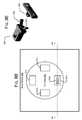
FIG. 8B is an illustration of a top cross-sectional view of a vehicle base station in accordance with embodiments.
FIG. 9A is a perspective view of a modular battery pack according to embodiments.
FIGS. 9B-9D are illustrations of perspective views of a modular battery case and a battery receptacle in accordance with embodiments.
FIG. 9E is a schematic, perspective view of a locking anchor and a locking component, according to embodiments.
FIG. 10 is a flowchart illustrating operations in a method to replace a payload on a vehicle, according to embodiments.
SUMMARY
Described herein is an exemplary system to load and unload material from a vehicle. In some embodiments the system comprises a vehicle base station and an assembly to autonomously load and unload material from the vehicle.
In another embodiment a method to replace a first payload on a vehicle comprises positioning the vehicle on a platform of a vehicle base station such that the first payload is aligned with an aperture in the platform, aligning an empty docking station in a payload advancing assembly with the aperture, removing the first payload from the vehicle, placing the first payload in the empty docking station of the payload advancing assembly, advancing the payload advancing assembly to align a full docking station with the aperture, and securing a second payload to the vehicle.
DETAILED DESCRIPTION
In the following description, numerous specific details are set forth to provide a thorough understanding of various embodiments. However, it will be understood by those skilled in the art that the various embodiments may be practiced without the specific details. In other instances, well-known methods, procedures, components, and elements have not been illustrated or described in detail so as not to obscure the particular embodiments.
One embodiment of a vehicle loading platform will be described with reference to an unmanned aerial vehicle (UAV) environment. An unmanned aerial vehicle (UAV) is an aircraft that is capable of flying without human operators being present in the aircraft. Unmanned aerial vehicles may be controlled from a remote location. At this remote location, a human operator or a program executed by a computer generates commands for the unmanned aerial vehicle. Unmanned aerial vehicles also may be controlled using a program running on a computer or other controller on the unmanned aerial vehicle.
Unmanned aerial vehicles are used for a number of different purposes. In military and security applications, unmanned aerial vehicles may be used to perform missions that may include, for example, without limitation, reconnaissance missions, attack missions, and/or other suitable types of missions. Unmanned aerial vehicles also may be used in a number of civilian applications. For example, without limitation, unmanned aerial vehicles may be used to perform surveying, firefighting, and/or other suitable types of missions.
Unmanned aerial vehicles may come in a number of different sizes and shapes. Unmanned aerial vehicles may, for example, take the form of fixed wing aircraft, helicopters, and/or ornithopters. For example, without limitation, an unmanned aerial vehicle may take the form of an airplane, a helicopter, or some other suitable type of device capable of flying. The size of an unmanned aerial vehicle may vary greatly. For example, an unmanned aerial vehicle may have a wing span from about a few inches to about 200 feet, depending on the type of unmanned aerial vehicle.
Smaller unmanned aerial vehicles are referred to as micro air vehicles. These types of air vehicles may be configured to be carried by a person and may be launched by throwing the micro air vehicles in the air. The small size of these types of air vehicles allows this type of launching method to provide sufficient velocity for these air vehicles to begin flight. The size of unmanned aerial vehicles has been reduced in part because of a reduction in the sizes of sensors, motors, power supplies, and controllers for these types of vehicles.
Reductions in vehicle size and cost make it possible to operate these vehicles in large numbers. For example, micro air vehicles (MAVs) may be operated in numbers that are about the size of a squad or platoon, as compared to operating one or two larger unmanned aerial vehicles. This type of operation increases the monitoring that can be performed for a particular area. These types of unmanned aerial vehicles also may land on a perch, a building, or another location. In this manner, a micro air vehicle may monitor a particular location without having to continue flight. The micro air vehicle may be repositioned if the area of interest changes.
For example, a micro air vehicle may land on a building in a city or town. The micro air vehicle may monitor a particular road or building in the city. Micro air vehicles, however, have limitations with their smaller size, as compared to larger unmanned aerial vehicles. For example, the processing power and data transmission ranges may be more limited for micro air vehicles, as compared to larger unmanned aerial vehicles. Further, the range of these micro air vehicles may be shorter, as compared to the larger unmanned aerial vehicles.
Various embodiments described herein provide a vehicle base station for autonomous vehicles including unmanned aerial vehicles. In some embodiments, a base station comprises a housing defining at least one platform to support at least one vehicle carrying a payload, a vehicle docking assembly to align the payload at a desired location on the platform, and a payload replacement assembly to remove the payload from the vehicle and to replace the payload with a new payload. Various aspects of embodiments of vehicle base stations and unmanned aerial vehicles will be explained with reference to the figures, below.
With reference to FIG. 1, an illustration of an unmanned aerial vehicle environment is depicted in accordance with an embodiment. Unmanned aerial vehicle environment 100 includes unmanned aerial vehicle base station 102, unmanned aerial vehicle base station 104, and unmanned aerial vehicle base station 106.
In the example depicted in FIG. 1, unmanned aerial vehicle base station 102 is located on rooftop 108 of building 110 within a town 112. Unmanned aerial vehicle base station 104 is associated with vehicle 114. A first component may be considered to be associated with a second component by being secured to the second component, bonded to the second component, fastened to the second component, and/or connected to the second component in some other suitable manner. The first component also may be connected to the second component by a third component. The first component may be considered to be associated with the second component by being formed as part of and/or an extension of the second component.
Unmanned aerial vehicle base station 106 is located on power lines 116. Unmanned aerial vehicle base stations 102, 104, and 106 may be deployed in a number of different ways. Unmanned aerial vehicle base station 102 may be dropped off by helicopter on rooftop 108. The location of unmanned aerial vehicle base station 102 on rooftop 108 may result in unmanned aerial vehicle base station 102 being less observable. Further, this location may provide a better line of sight between unmanned aerial vehicle base station 102 and communication arrays. In this manner, the range at which unmanned aerial vehicle base station 102 may communicate with unmanned aerial vehicles may be increased.
Unmanned aerial vehicle base station 104 is associated with vehicle 114. By being associated with vehicle 114, unmanned aerial vehicle base station 104 may be moved periodically or constantly. This type of deployment may reduce the discoverability of unmanned aerial vehicle base station 104. Further, by providing mobility to unmanned aerial vehicle base station 104, greater flexibility may be present for performing missions. In addition, unmanned aerial vehicle base station 104 may be removed from vehicle 114 and placed on the ground or in some other suitable location.
Unmanned aerial vehicle base station 106 may be deployed onto power lines 116 by being dropped by a helicopter, on a parachute, or some other suitable mechanism. Unmanned aerial vehicle base station 106 may be less observable on power lines 116. As depicted, unmanned aerial vehicles, such as unmanned aerial vehicles 118, 120, 122, 124, 126, 128, 130, 132, 134, 136, and 138 may operate from unmanned aerial vehicle base stations 102, 104, and 106.
In these illustrative examples, unmanned aerial vehicle base stations 102, 104, and 106 provide a base from which the different unmanned aerial vehicles may transmit data, receive instructions, recharge, be stored, and/or perform other operations.
Additionally, unmanned aerial vehicles may travel from base station to base station. In other words, unmanned aerial vehicle base stations 102, 104, and 106 may provide a network to extend the range of unmanned aerial vehicles. Having multiple unmanned aerial vehicle base stations also may provide backup in case one unmanned aerial vehicle base station malfunctions or fails to perform as needed.
As can be seen in this depicted example, unmanned aerial vehicle base stations 102, 104, and 106 may be placed in locations where detection of those base stations may be reduced. These locations may include other locations other than those illustrated in this particular example. For example, unmanned aerial vehicle base stations 102, 104, and 106 may be placed in trees, in brush, and/or in other suitable locations.
The unmanned aerial vehicles may be used to perform a number of different missions in unmanned aerial vehicle environment 100. In this illustrative example, the unmanned aerial vehicles may monitor for undesired activity. For example, the undesired activity may be the placement of an improvised explosive device in roadway 140. In another example, the unmanned aerial vehicles may monitor for movement of vehicles or people. In still other examples, unmanned aerial vehicles may be used to monitor for construction of structures.
With reference now to FIG. 2, an illustration of a block diagram of an unmanned aerial vehicle base station is depicted in accordance with an advantageous embodiment. Unmanned aerial vehicle base station 200 is an example of an unmanned aerial vehicle base station that may be used to implement unmanned aerial vehicle base stations 102, 104, and 106 in FIG. 1.
In this illustrative example, unmanned aerial vehicle base station 200 comprises platform 202, battery system 204, power generation system 206, number of charging stations 208, controller 210, sensor system 212, and/or other suitable components.
Platform 202 is configured to hold one or more unmanned aerial vehicles 214. In other words, number of unmanned aerial vehicles 214 may be placed in and/or stored in or on platform 202. For example, platform 202 may have bay 216 in which number of unmanned aerial vehicles 214 may land. Bay 216 may be an area of platform 202 surrounded by walls with an opening on the top side of platform 202. In other advantageous embodiments, bay 216 may have walls and a roof with an opening on the side of platform 202. An unmanned aerial vehicle is considered to be housed when the unmanned aerial vehicle enters into or lands on platform 202.
Additionally, platform 202 may be configured to provide protection from environment 224 for number of unmanned aerial vehicles 214 when number of unmanned aerial vehicles 214 is housed in platform 202.
Platform 202 also may have movable cover system 218 that is configured to move between open position 220 and closed position 222. Movable cover system 218 may cover bay 216. When movable cover system 218 is in open position 220, number of unmanned aerial vehicles 214 may take off from and/or land in or on platform 202.
When movable cover system 218 is in closed position 222, number of unmanned aerial vehicles 214 located in bay 216 of platform 202 may be protected from environment 224. Further, closed position 222 also provides a configuration for transporting number of unmanned aerial vehicles 214 in unmanned aerial vehicle base station 200.
Battery system 204 and power generation system 206 provide electrical energy 226 for unmanned aerial vehicle base station 200 and number of unmanned aerial vehicles 214. Battery system 204 is optional and stores electrical energy 226 generated by power generation system 206. Power generation system 206 generates electrical energy 226 from environment 224 in which unmanned aerial vehicle base station 200 is located.
A number of charging stations 208 are connected to battery system 204. Charging stations 208 are configured to charge batteries for a number of unmanned aerial vehicles 214 using electrical energy 226. Further, charging stations 208 provide electrical energy 226 to controller 210 and sensor system 212 in unmanned aerial vehicle base station 200.
In some embodiments, aerial vehicles 214 may take the form of liquid fueled unmanned aerial vehicles. In these illustrative examples, charging stations 208 is configured to refuel these liquid fueled unmanned aerial vehicles. For example, unmanned aerial vehicle base station 200 may have liquid refueling system 244. Liquid refueling system 244 has liquid fuel tank 246 containing liquid fuel. The liquid fuel may be, for example, gasoline or diesel fuel. Pump 248 in liquid refueling system 244 transfers the liquid fuel in liquid fuel tank 246 to number of charging stations 208. Charging stations 208 may be configured to provide liquid fuel to the liquid fuel unmanned aerial vehicles.
In these embodiments, controller 210 may be configured to control the pumping of liquid fuel from liquid refueling system 244. In some embodiments, liquid refueling system 244 may deliver liquid fuel to one or more unmanned aerial vehicles 214 at number of charging stations 208 using a syringe injection system.
In these embodiments, controller 210 may be configured to receive sensor data 236 from number of unmanned aerial vehicles 214. Additionally, controller 210 may be configured to generate information 238 from sensor data 236. Information 238 may then be sent to remote location 240. Remote location 240 is a location remote to unmanned aerial vehicle base station 200. The remote location may include a mission planning system or a human operator. Controller 210 may also be configured to program each of number of unmanned aerial vehicles 214 with mission 242. Mission 242 may be the same or different for each of number of unmanned aerial vehicles 214.
Sensor system 212 generates sensor data 248 from environment 224. Sensor data 248 may be sent to remote location 240 or may be used to send commands 250 to number of unmanned aerial vehicles 214.
The illustration of unmanned aerial vehicle base station 200 in FIG. 2 is not meant to imply physical or architectural limitations to the manner in which different advantageous embodiments may be implemented. Other components in addition to and/or in place of the ones illustrated may be used. Some components may be unnecessary in some advantageous embodiments. Also, the blocks are presented to illustrate some functional components. One or more of these blocks may be combined and/or divided into different blocks when implemented in different embodiments.
For example, in some embodiments, different forms of energy may be stored in storage devices for conversion into electrical energy for number of unmanned aerial vehicles 214. These storage devices may be devices other than battery system 204. These devices may include, for example, without limitation, capacitors, flywheels, compressed air devices, and/or other suitable energy storage devices. One or more of these devices may be connected to charging stations 208. In some embodiments a base station may comprise a system to replace a battery pack (or other payload) on a vehicle. Further, a base station may comprise an assembly to recharge one or more batteries. Embodiments of such base station are described below with reference to FIGS. 8A and 8B.
Turning to FIG. 3, an illustration of a block diagram of a data processing system is depicted in accordance with an embodiment. Data processing system 300 is an example of an implementation for controller 210 in FIG. 2. In this illustrative example, data processing system 300 includes communications fabric 302, which provides communications between processor unit 304, memory 306, persistent storage 308, communication unit 310, and input/output (I/O) unit 312.
Processor unit 304 serves to execute instructions for software that may be loaded into memory 306. Processor unit 304 may be a set of one or more processors or may be a multi-processor core, depending on the particular implementation. Further, processor unit 304 may be implemented using one or more heterogeneous processor systems in which a main processor is present with secondary processors on a single chip. As another illustrative example, processor unit 304 may be a symmetric multi-processor system containing multiple processors of the same type.
Memory 306 and persistent storage 308 are examples of storage devices 316. A storage device is any piece of hardware that is capable of storing information, such as, for example, without limitation, data, program code in functional form, and/or other suitable information either on a temporary basis and/or a permanent basis. Memory 306, in these examples, may be, for example, a random access memory or any other suitable volatile or non-volatile storage device.
Persistent storage 308 may take various forms, depending on the particular implementation. For example, persistent storage 308 may contain one or more components or devices. For example, persistent storage 308 may be a hard drive, a flash memory, a rewritable optical disk, a rewritable magnetic tape, or some combination of the above. The media used by persistent storage 308 may be removable. For example, a removable hard drive may be used for persistent storage 308.
Communication unit 310, in these examples, provides for communication with other data processing systems or devices. In these examples, communications unit 310 is a network interface card. Communications unit 310 may provide communications through the use of either or both physical and wireless communications links.
Communications unit 310 is configured to provide wireless communications links. These wireless communications links may include, for example, without limitation, a satellite communications link, a microwave frequency communications link, a radio frequency communications link, and/or other suitable types of wireless communication links.
Input/output unit 312 allows for the input and output of data with other devices that may be connected to data processing system 300. For example, input/output unit 312 may provide a connection for user input through a keyboard, a mouse, and/or some other suitable input device. Further, input/output unit 312 may send output to a printer. Display 314 provides a mechanism to display information to a user.
Instructions for the operating system, applications, and/or programs may be located in storage devices 316, which are in communication with processor unit 304 through communications fabric 302. In these illustrative examples, the instructions are in a functional form on persistent storage 308. These instructions may be loaded into memory 306 for execution by processor unit 304. The processes of the different embodiments may be performed by processor unit 304 using computer implemented instructions, which may be located in a memory, such as memory 306.
These instructions are referred to as program code, computer usable program code, or computer readable program code that may be read and executed by a processor in processor unit 304. The program code, in the different embodiments, may be embodied on different physical or computer readable storage media, such as memory 306 or persistent storage 308.
Program code 318 is located in a functional form on computer readable media 320 that is selectively removable and may be loaded onto or transferred to data processing system 300 for execution by processor unit 304. Program code 318 and computer readable media 320 form computer program product 322. In one example, computer readable media 320 may be computer readable storage media 324 or computer readable signal media 326.
Computer readable storage media 324 may include, for example, an optical or magnetic disk that is inserted or placed into a drive or other device that is part of persistent storage 308 for transfer onto a storage device, such as a hard drive, that is part of persistent storage 308. Computer readable storage media 324 also may take the form of a persistent storage, such as a hard drive, a thumb drive, or flash memory that is connected to data processing system 300. In some instances, computer readable storage media 324 may not be removable from data processing system 300.
Alternatively, program code 318 may be transferred to data processing system 300 using computer readable signal media 326. Computer readable signal media 326 may be, for example, a propagated data signal containing program code 318. For example, computer readable signal media 326 may be an electromagnetic signal, an optical signal, and/or any other suitable type of signal. These signals may be transmitted over communication links, such as wireless communications links, an optical fiber cable, a coaxial cable, a wire, and/or any other suitable type of communication link. In other words, the communication link and/or the connection may be physical or wireless in the illustrative examples.
In some embodiments, program code 318 may be downloaded over a network to persistent storage 308 from another device or data processing system through computer readable signal media 326 for use within data processing system 300. For instance, program code stored in a computer readable storage media in a server data processing system may be downloaded over a network from the server to data processing system 300. The data processing system providing program code 318 may be a server computer, a client computer, or some other device capable of storing and transmitting program code 318.
The different components illustrated for data processing system 300 are not meant to provide architectural limitations to the manner in which different embodiments may be implemented. The different illustrative embodiments may be implemented in a data processing system, including components in addition to or in place of those illustrated for data processing system 300. Other components shown in FIG. 3 can be varied from the illustrative examples shown. The different embodiments may be implemented using any hardware device or system capable of executing program code. As one example, data processing system 300 may include organic components integrated with inorganic components and/or may be comprised entirely of organic components excluding a human being. For example, a storage device may be comprised of an organic semiconductor.
As another example, a storage device in data processing system 300 is any hardware apparatus that may store data. Memory 306, persistent storage 308, and computer readable media 320 are examples of storage devices in a tangible form.
In another example, a bus system may be used to implement communications fabric 302 and may be comprised of one or more buses, such as a system bus or an input/output bus. Of course, the bus system may be implemented using any suitable type of architecture that provides for a transfer of data between different components or devices attached to the bus system. Additionally, a communications unit may include one or more devices used to transmit and receive data, such as a modem or a network adapter. Further, a memory may be, for example, memory 306 or a cache such as found in an interface and memory controller hub that may be present in communications fabric 302.
With reference to FIG. 4, an illustration of a block diagram of a power generation system is depicted in accordance with an advantageous embodiment. Power generation system 400 is an example of one implementation for power generation system 206 in FIG. 2. Power generation system 400 generates electrical energy 401 in these illustrative examples.
Power generation system 400 may include energy harvesting system 402. Energy harvesting system 402 may comprise at least one of solar power generation unit 404, inductive power generation unit 406, wind power generation unit 408, and/or other suitable types of energy harvesting units. Power generation system 400 also may include radioisotope thermal electrical generation unit 410, power converter 412, and/or other suitable types of power generation devices, e.g., fuel cells, batteries, electric generators, or electric outlets.
As used herein, the phrase “at least one of”, when used with a list of items, means that different combinations of one or more of the listed items may be used and only one of each item in the list may be needed. For example, “at least one of item A, item B, and item C” may include, for example, without limitation, item A or item A and item B. This example also may include item A, item B, and item C, or item B and item C. In other examples, “at least one of” may be, for example, without limitation, two of item A, one of item B, and 10 of item C; four of item B and seven of item C; and other suitable combinations.
Solar power generation unit 404 generates electrical energy 401 from exposure to sunlight or other light in the environment. Solar power generation unit 404 may comprise solar energy cells 416. In the different illustrative examples, solar energy cells 416 may take the form of photovoltaic units. Solar energy cells 416 may be located on, for example, without limitation, movable cover system 218 in FIG. 2.
Inductive power generation unit 406 generates power inductively when an alternating current source is present, such as in power lines. This power may be used to provide electrical energy 401. Wind power generation unit 408 may include a number of wind power turbines that generate electrical energy 401 from wind that may be present in the environment.
Radioisotope thermal electrical generation unit 410 generates electrical energy 401 from radioactive material that decays. The decay of the radioactive material generates heat used by radioisotope thermal electrical generation unit 410 to generate electrical energy 401. This radioactive material is carried by the unmanned aerial vehicle base station in these examples.
Power converter 412 converts electrical power from one form to another form. For example, power converter 412 may convert alternating current (AC) energy into direct current (DC) energy. Power converter 412 also may change the frequency of alternating current energy as another example. In yet another example, power converter 412 may change the current flow. Power converter 412 may be used when a power source, such as an electrical outlet, is present. In these illustrative examples, power converter 412 converts energy into electrical energy 401 for use by an unmanned aerial vehicle.
Referring now to FIG. 5, an illustration of a block diagram of a sensor system is depicted in accordance with an advantageous embodiment. Sensor system 500 is an example of one implementation for sensor system 212 in FIG. 2. In these illustrative examples, sensor system 500 generates sensor data 501. Sensor system 500, in this example, includes camera system 502, global positioning system unit 504, weather sensors 506, and motion detector 508.
Camera system 502 may comprise number of cameras 510. Cameras 510 may include at least one of visible light camera 512, infrared camera 514, and other suitable types of cameras. In some advantageous embodiments, visible light camera 512 and infrared camera 514 are combined as part of a multispectral camera.
Camera system 502 generates sensor data 501 in the form of image data 518. Global positioning system unit 504 generates location information 520 in sensor data 501. Location information 520 may include, for example, latitude, longitude, and an elevation. Additionally, time information 522 also may be generated by global positioning system unit 504.
Weather sensors 506 generate weather data 524 in sensor data 501 that may be used to identify weather conditions. For example, weather sensors 506 may generate information about wind speed, pressure, wind direction, humidity, temperature, and/or other suitable information.
Motion detector 508 generates motion data 526 in sensor data 501. Motion detector 508 generates motion data 526 when motion in an area monitored by motion detector 508 is detected.
Turning now to FIG. 6, an illustration of a block diagram of a charging station is depicted in accordance with an advantageous embodiment. Charging station 600 is an example of an implementation for a charging station within number of charging stations 208 in FIG. 2.
Charging station 600 may comprise at least one of inductive charging system 602 and conductive charging system 604. Inductive charging system 602 generates magnetic field 606. Magnetic field 606 may induce another magnetic field in a coil located within the device being charged. In this manner, the current may be caused to flow in the device being charged without contact between inductive charging system 602 and the device.
Conductive charging system 604 includes contacts 608. Contacts 608 may be placed in physical contact with contacts on the device being charged. This contact allows for electrical current 610 to flow from conductive charging system 604 to the device being charged by charging station 600. In this manner, the device may be charged and/or recharged to perform additional operations or missions.
Turing now to FIG. 7, an illustration of a block diagram of an unmanned aerial vehicle is depicted in accordance with an advantageous embodiment. Unmanned aerial vehicle 700 is an example of one implementation for number of unmanned aerial vehicles 214 in FIG. 2. In some embodiments the vehicles may include manned aerial vehicles or vehicles other than aerial vehicles, e.g., ground vehicles such as cars, trucks, tanks, or the like.
In this illustrative example, unmanned aerial vehicle 700 may take a number of forms. For example, unmanned aerial vehicle 700 may be, for example, without limitation, airplane 702, helicopter 704, ornithopter 706, or some other suitable type of aircraft.
As illustrated, unmanned aerial vehicle 700 comprises body 708, propulsion system 710, battery 712, charging system 714, processor unit 716, storage device 718, wireless communications device 720, and number of sensors 722. Body 708 provides a structure in which the different components of unmanned aerial vehicle 700 may be associated with each other. For example, without limitation, body 708 may be a fuselage. Further, body 708 may include aerodynamic surfaces, such as wings or other types of surfaces.
Propulsion system 710 is configured to move unmanned aerial vehicle 700 in the air. Propulsion system 710 may be, for example, without limitation, an electric motor configured to rotate a propeller or other type of blade. In other advantageous embodiments, propulsion system 710 may be configured to move wings on body 708 when unmanned aerial vehicle 700 takes the form of ornithopter 706. Battery 712 provides electrical energy for unmanned aerial vehicle 700.
Charging system 714 is connected to battery 712 and allows battery 712 to be recharged at a charging station. Charging system 714 may include inductive coils for an inductive charging system or conductive contacts for a conductive charging system. In some advantageous embodiments, charging system 714 also may be used to transfer data. As one illustrative example, charging system 714 may provide a modulated charge as a carrier frequency. This modulated charge allows for the transfer of data in addition to the providing of power.
As another illustrative example, conductive contacts in charging system 714 may be used to transfer data. In other advantageous embodiments, power may be provided wirelessly by charging system 714 using microwaves or a laser.
Processor unit 716 runs a number of programs for missions in these illustrative examples. Storage device 718 may store sensor data 724 generated by sensors 722. Additionally, storage device 718 may store mission 726 that is executed or run by processor unit 716. Mission 726 may be, for example, without limitation, a program, an identification of a target, and/or other suitable types of information.
Wireless communication device 720 is configured to provide communications between unmanned aerial vehicle 700 and a remote location, such as unmanned aerial vehicle base station 200 or remote location 240 in FIG. 2. In these illustrative examples, number of sensors 722 may include, for example, at least one of visible light camera 728, infrared light camera 730, motion detector 732, and/or other suitable types of sensors used to generate sensor data 724 for processing by processor unit 716.
The illustration of unmanned aerial vehicle base station 200 and its components in FIGS. 2-6 and unmanned aerial vehicle 700 in FIG. 7 are not meant to imply physical or architectural limitations to the manner in which different advantageous embodiments may be implemented. Other components in addition to and/or in place of the ones illustrated may be used. Some components may be unnecessary in some advantageous embodiments. Also, the blocks are presented to illustrate some functional components. One or more of these blocks may be combined and/or divided into different blocks when implemented in different advantageous embodiments.
For example, in some embodiments, unmanned aerial vehicle base station 200 may not include movable cover system 218. Instead, bay 216 may be configured to provide protection from environment 224 without moving parts. For example, bay 216 may be a cavity in platform 202 with an opening configured to protect number of unmanned aerial vehicles 214 from environment 224. Additionally, in some embodiments, unmanned aerial vehicle 700 may not have wireless communications device 720. Instead, a wired contact may be used to transfer data from unmanned aerial vehicle 700 to unmanned aerial vehicle base station 200 when unmanned aerial vehicle 700 lands on platform 202.
In some embodiments a vehicle base station may be adapted to include an assembly for automatically removing a payload from a vehicle and replacing the payload. In embodiments described herein the payload comprises a modular battery case which is selectably attachable to a battery receptacle on the vehicle. Further, the vehicle base station may be adapted to recharge batteries removed from the vehicles.
One embodiment of a vehicle base station 800 depicted in FIG. 8A and FIG. 8B. FIG. 8A is an illustration of a side cross-sectional view of a vehicle base station 800, and FIG. 8B is an illustration of a top cross-sectional view of a vehicle base station 800 in accordance with embodiments. In some embodiments, a vehicle base station 800 comprises a housing 810 defining at least one platform 820 to support at least one vehicle 830 carrying a payload 840, a vehicle docking assembly 850 to align the payload 840 at a desired location on the platform 820, and a payload replacement assembly 860 to remove the payload 840 from the vehicle 830 and to replace the payload 840 with a new payload 840.
Referring to FIG. 8A and FIG. 8B, in some embodiments the housing 810 comprises a base 812, walls 814 and a platform 820 which define an internal chamber. An aperture 822 in the platform 820 provides access to the internal chamber. The dimensions of the housing 810 are not critical, and may be a function of the size of vehicle 830 for which the housing 810 is adapted. For smaller vehicles such as the micro air vehicles described above the housing may be dimensioned such that it is readily portable. For larger vehicles, e.g., unmanned aerial vehicles or manned aerial vehicles the housing 810 would need to be larger.
A vehicle 830 such as, e.g., an aircraft or an automobile, may be positioned on the platform 820. In the embodiment depicted in FIG. 8A the vehicle 830 is an unmanned aerial vehicle comprising a body 832, a frame structure 834, rotors 836 and supports 838.
In some embodiments a vehicle docking assembly 850 is coupled to the platform 820 to secure the vehicle 820 in an appropriate location above the aperture 822 in the platform. In the embodiment depicted herein the vehicle docking assembly 850 comprises an alignment mechanism to align the vehicle in a predetermined position on the platform. By way of example, the vehicle docking assembly 850 may comprise one or more electromagnetic pads 850 positioned on the surface of the platform 820. When activated, electromagnetic pads 850 generate a magnetic force to secure the supports 838 of the vehicle 830 to the platform 820.
A payload replacement assembly 860 is positioned within the chamber defined by the housing 810. In the embodiment depicted in FIGS. 8A and 8B the payload replacement assembly 860 comprises a hoist assembly 862 which raises a payload platform 864 from a first position, as illustrated in FIG. 8A, in which the payload platform 862 is displaced from a payload 840 to a second position in which the payload platform contacts a payload 840 mounted on the vehicle 830. The hoist assembly 860 may be actuated by a conventional motor 866.
A payload advancing assembly 870 cooperates with the payload replacement assembly to receive a payload 840 from the vehicle 830 and to advance a payload 840 into a position from which the payload may be hoisted onto the vehicle 830. In the embodiment depicted in FIGS. 8A and 8B the payload advancing assembly comprises a turntable 872 which rotates about a central axis. The platform comprises a plurality of docking stations 874 to hold a payload 840. In some embodiments the docking stations 874 define an aperture in the turntable 872 through which the payload platform 864 may pass when the hoist assembly 860 raises the payload platform 864 to contact the payload 840. Thus, referring to FIG. 8B, the payload platform 864 is visible through the aperture in the docking station 874 of the turntable 872.
While the specific composition of the payload 840 is not critical, in some embodiments the payload 840 may comprise one or more batteries from which the vehicle 830 draws power. In such embodiments the docking stations 874 may comprise or be coupled to a battery charging substation such that batteries removed from the vehicle 830 may be recharged while they are positioned on the turntable 872.
In some embodiments one or more batteries for the vehicle 830 may be stored within a modular battery pack that is adapted to engage with a receptacle that may be coupled to the vehicle 830. FIG. 9A is a perspective view of a modular battery pack 900 according to embodiments. Referring to FIG. 9A, a modular battery pack 900 may comprise a lower portion 910 and an upper portion 920, which define an internal chamber into which one or more batteries may be placed. The upper surface 922 of the upper portion 920 comprises one or more alignment pins 924 and one or more locking anchors 930 which facilitate coupling the battery pack 900 to a receptacle 940 (See FIG. 9B) mounted on the vehicle 830.
FIGS. 9B-9D are illustrations of perspective views of a modular battery case 900 and a battery receptacle 940 in accordance with embodiments. Referring to FIGS. 9B-9D, the battery receptacle 940 comprises four walls 942 and a top 944 which define an open-bottomed chamber to receive a battery pack 900. The top 944 comprises one or more holes 948 to receive the alignment pins 924 and one or more locking components 946 to receive the locking anchors 930 on the battery pack.
FIG. 9E is a schematic, perspective view of a locking anchor 930 and a locking component 946, according to embodiments. Referring briefly to FIG. 9E, the locking anchor 930 may be coupled to the locking component 946, the jaws 948 of which close and lock onto the locking anchor 930. When the engagement/disengagement button 950 is depressed the jaws release the locking anchor 930.
Having described various structural components of an example vehicle base station, methods of using such a base station will now be describe. In some embodiments a vehicle base station as described herein may be used to implement a method to replace a payload 840 on a vehicle 830, which will be described with reference to FIG. 10.
In use, a vehicle such as vehicle 830 is positioned (operation 1010) on the platform 820 of the housing 810. In the case of an airborne vehicle such as a UAV or an MAV, the airborne vehicle may be landed directly on the platform. Alternatively, the airborne vehicle may be landed elsewhere and manually positioned on the platform 820. In the case of a land-based vehicle the vehicle may be driven directly onto the platform 820 or may be driven near the platform then manually positioned on the platform 820.
When the vehicle 830 is positioned on the platform the alignment assembly 850 may be activated to align the payload 840 over the aperture 822 in the platform 820. In the embodiment depicted in FIG. 8A the electromagnetic pads 850 may be activated to position and secure the vehicle 830 over the aperture 822 in the platform 820.
At operation 1015 an empty docking station is aligned with the aperture 822 in the platform 820. In the embodiment depicted in FIGS. 8A and 8B, the rotating turntable 872 may be advanced such that an empty docking station 874 is beneath the aperture 822 in the platform. When the rotating turntable is in this position the payload platform 864 is positioned underneath the empty docking station.
At operation 1020 the first payload 840 is removed from the vehicle 830. In the embodiment depicted in FIGS. 8A and 8B the hoist assembly 862 raises the payload platform 864 through the empty docking station 874 in the turntable 872 such that the payload platform 864 contacts the payload 840 on the vehicle. In embodiments in which the payload comprises a modular battery case 900 as described with reference to FIGS. 9A-9E the payload platform 864 applies pressure to the modular battery case 900, which cases the locking anchor 930 to depress the engagement/disengagement button 950 on the locking component 946. This, in turn, causes the jaws 948 of the locking component to release the locking anchor 930, thereby automatically releasing the payload 840 from the vehicle. The payload 830 then rests on the payload platform 864.
At operation 1025 the payload 840 removed from the vehicle in operation 1020 is placed in an empty docking station 874. In the embodiment depicted in FIGS. 8A and 8B the hoist assembly 862 lowers the payload platform 864 through the empty docking station 874 in the turntable 872. In some embodiments the modular battery case 900 is dimensioned such that it is smaller than the aperture in the empty docking station 874, such that the modular battery case passes through the aperture in the empty docking station.
At operation 1030 the payload advancing assembly is advanced to position a new payload 840 in the aperture 822 beneath the vehicle 830 on the platform 820. In the embodiment depicted in FIGS. 8A and 8B the turntable 872 is rotated to position a new payload 840 in the aperture 822 beneath the vehicle 830.
At operation 1035 the new payload is secured to the vehicle. In the embodiment depicted in FIGS. 8A and 8B the hoist assembly raises the payload platform 864 through the docking station 874 in the turntable 872 such that the payload is lifted off the payload platform 864 and up to the vehicle 830. In embodiments in which the payload comprises a modular battery case 900 as described with reference to FIGS. 9A-9E the payload platform 864 applies pressure to the modular battery case 900, which causes the locking anchor 930 to depress the engagement/disengagement button 950 on the locking component 946. This, in turn, causes the jaws 948 of the locking component to lock onto the locking anchor 930, thereby automatically securing the payload 840 to the vehicle 830. The payload platform 864 may then be lowered back through the docking station 874 in the turntable 872.
As described above, in some embodiments the payload 840 may comprise at least one battery. In such embodiments the base station 800 may comprise, or be coupled to, a battery charging station to recharge batteries removed from the vehicle 830. By way of example and not limitation in some embodiments the docking stations 874 in the turntable 872 may comprise a battery charging terminal such that batteries stored in the docking stations 874 are charged. In such embodiments the modular battery case 900 is larger than the aperture in the empty docking station 874, such that the modular battery case 900 is positioned in docking station 874 on the turntable 872 when the payload platform 846 drops through the aperture in the empty docking station 874. The battery may then be charged while it is positioned in the docking station 874.
Thus, described herein are exemplary embodiments of a vehicle loading station and associated methods for using a vehicle loading station. In some embodiments the vehicle loading station comprises a housing which defines at least one platform onto which a vehicle carrying a payload may be positioned. A vehicle docking assembly docks and secures the vehicle on the platform. A payload replacement assembly removes a payload from the vehicle and replaced with a new payload.
In some embodiments the payload 840 may comprise one or more batteries. In other embodiments the payload 840 may comprise a transport payload, e.g., materials or goods. In other embodiments the payload 840 may comprise a dispensable payload such as water or a fire suppressant.
Reference in the specification to “one embodiment” or “some embodiments” means that a particular feature, structure, or characteristic described in connection with the embodiment is included in at least an implementation. The appearances of the phrase “in one embodiment” in various places in the specification may or may not be all referring to the same embodiment.
Although embodiments have been described in language specific to structural features and/or methodological acts, it is to be understood that claimed subject matter may not be limited to the specific features or acts described. Rather, the specific features and acts are disclosed as sample forms of implementing the claimed subject matter.

Claims (14)

What is claimed is:
1. A system, comprising:
a vehicle base station on which a vehicle may be positioned;
a modular battery case, comprising:
a housing comprising a lower portion and an upper portion defining a chamber capable of holding one or more batteries;
at least one alignment pin extending from an upper surface of the upper portion of the housing to facilitate appropriate alignment of the modular battery case with a battery receptacle on the vehicle, the battery receptacle comprising at least one locking component, the locking component comprising opposing jaws; and
at least one locking anchor extending from the upper surface of the upper portion of the housing and positioned to be received by the locking component when the modular battery case is inserted into the battery receptacle, wherein the opposing jaws are operable to close and lock onto the at least one locking anchor; and
an assembly to autonomously load and unload the modular battery case from the vehicle.
2. The system of claim 1, wherein the vehicle base station, comprises:
a second housing defining at least one platform to support the vehicle;
a vehicle docking assembly to align a payload carried by the vehicle at a location on the at least one platform; and
a payload replacement assembly to remove the payload from the vehicle and to replace the payload with a new payload.
3. The system of claim 2, further comprising a battery recharging assembly to recharge the one or more batteries.
4. The system of claim 2, wherein the at least one locking component further comprises a disengagement button disposed between the opposing jaws which, when depressed, causes the opposing jaws to disengage the at least one locking anchor.
5. The system of claim 4, wherein the payload replacement assembly activates the disengagement button to release the modular battery case from the battery receptacle.
6. The system of claim 5, wherein the payload replacement assembly applies pressure to the modular battery case, thereby causing the at least one locking anchor to depress the disengagement button to release the modular battery case from the battery receptacle.
7. The system of claim 4, wherein the modular battery case fits a variety of battery types.
8. The system of claim 2, wherein the payload replacement assembly comprises a hoist assembly comprising a payload platform moveable between a first position in which the payload platform is displaced from the payload carried by the vehicle to a second position in which the payload platform contacts the payload.
9. The system of claim 8, further comprising a payload advancing assembly to advance the payload into a third position from which the hoist assembly can secure the payload to the vehicle.
10. The system of claim 9, wherein:
the at least one platform comprises at least one aperture;
the payload advancing assembly comprises a rotatable turntable positioned beneath the at least one platform;
the rotating turntable comprises a plurality of docking stations, each docking station defining a first aperture; and
the hoist assembly configured to extend the payload platform through a second aperture in the turntable and through the at least one aperture in the at least one platform to contact the payload on the vehicle.
11. The system of claim 10, wherein the docking stations on the rotating turntable comprise a battery charging subsystem.
12. The system of claim 2, wherein the vehicle docking assembly comprises an alignment mechanism to align the vehicle in a predetermined position on the platform.
13. The system of claim 12, wherein the alignment mechanism comprises at least one electromagnet positioned on the platform.
14. The system of claim 1, wherein the battery receptacle fits heterogeneous vehicles including aircraft and ground vehicles.
US12/782,525 2010-05-18 2010-05-18 Vehicle base station Active 2031-07-27 US8899903B1 (en)

Priority Applications (3)

Application Number Priority Date Filing Date Title
US12/782,525 US8899903B1 (en) 2010-05-18 2010-05-18 Vehicle base station
US13/663,608 US8862288B2 (en) 2010-05-18 2012-10-30 Vehicle base station
US14/535,084 US9840380B2 (en) 2010-05-18 2014-11-06 Vehicle base station

Applications Claiming Priority (1)

Application Number Priority Date Filing Date Title
US12/782,525 US8899903B1 (en) 2010-05-18 2010-05-18 Vehicle base station

Related Child Applications (2)

Application Number Title Priority Date Filing Date
US81432210A Continuation-In-Part 2010-05-18 2010-06-11
US14/535,084 Division US9840380B2 (en) 2010-05-18 2014-11-06 Vehicle base station

Publications (1)

Publication Number Publication Date
US8899903B1 true US8899903B1 (en) 2014-12-02

Family

ID=51948296

Family Applications (2)

Application Number Title Priority Date Filing Date
US12/782,525 Active 2031-07-27 US8899903B1 (en) 2010-05-18 2010-05-18 Vehicle base station
US14/535,084 Active 2031-08-16 US9840380B2 (en) 2010-05-18 2014-11-06 Vehicle base station

Family Applications After (1)

Application Number Title Priority Date Filing Date
US14/535,084 Active 2031-08-16 US9840380B2 (en) 2010-05-18 2014-11-06 Vehicle base station

Country Status (1)

Country Link
US (2) US8899903B1 (en)

Cited By (99)

* Cited by examiner, † Cited by third party
Publication number Priority date Publication date Assignee Title
US20140252162A1 (en) * 2013-03-11 2014-09-11 Igor Teller Uav launching from moving platform
US20150123462A1 (en) * 2013-11-01 2015-05-07 Brian Kamradt Fueling station for unmaned arial vehicle of the vertical takeoff types
US9114719B1 (en) 2010-06-02 2015-08-25 Bryan Marc Failing Increasing vehicle security
US20150276353A1 (en) * 2014-03-28 2015-10-01 Mitsubishi Heavy Industries, Ltd. Modularized armor structure with unmanned aerial vehicle loaded and armored vehicle using the same
US20160257423A1 (en) * 2014-09-09 2016-09-08 Joseph Martin Unmanned Aerial Delivery System
US20160260049A1 (en) * 2015-03-06 2016-09-08 Wal-Mart Stores, Inc. Shopping facility assistance systems, devices, and methods to dispatch and recover motorized transport units that effect remote deliveries
US9454157B1 (en) * 2015-02-07 2016-09-27 Usman Hafeez System and method for controlling flight operations of an unmanned aerial vehicle
WO2016205415A1 (en) * 2015-06-15 2016-12-22 ImageKeeper LLC Unmanned aerial vehicle management
JP2016215796A (en) * 2015-05-19 2016-12-22 株式会社アドテックス Unmanned flying body and control system therefor
US9527605B1 (en) * 2014-12-18 2016-12-27 Amazon Technologies, Inc. Multi-use unmanned aerial vehicle docking station
US20170015415A1 (en) * 2015-07-15 2017-01-19 Elwha Llc System and method for operating unmanned aircraft
US9561871B2 (en) * 2014-05-07 2017-02-07 Deere & Company UAV docking system and method
US20170039861A1 (en) * 2015-08-04 2017-02-09 Qualcomm Incorporated Opportunistic Unmanned Autonomous Vehicle Energy Harvesting
WO2017072101A1 (en) * 2015-10-29 2017-05-04 Deutsche Post Ag Method for loading and/or unloading a transport device at a receiving container
US9656805B1 (en) * 2014-12-12 2017-05-23 Amazon Technologies, Inc. Mobile base utilizing transportation units for receiving items
WO2017109780A1 (en) * 2015-12-21 2017-06-29 Straus Itai Autonomous docking station for drones
US9714012B1 (en) 2016-01-22 2017-07-25 International Business Machines Corporation Power source element replacement during vehicle operation
US9764703B2 (en) 2016-01-22 2017-09-19 International Business Machines Corporation Power source element detection and monitoring
WO2017172840A1 (en) * 2016-03-28 2017-10-05 Andrew Bennett System and method for docking unmanned aerial vehicles (uavs)
US9783075B2 (en) 2015-10-05 2017-10-10 Asylon, Inc. Methods and apparatus for reconfigurable power exchange for multiple UAV types
WO2017221236A1 (en) * 2016-06-20 2017-12-28 Airobotics Ltd. Payload exchange facilitating connector
US9873408B2 (en) * 2016-05-11 2018-01-23 Peter D. Capizzo Device for refueling, exchanging, and charging power sources on remote controlled vehicles, UAVs, drones, or any type of robotic vehicle or machine with mobility
US20180065493A1 (en) * 2015-04-30 2018-03-08 SZ DJI Technology Co., Ltd. Charger, charging system with the charger, and aerial vehicle with the charger
US20180067198A1 (en) * 2016-05-27 2018-03-08 Uber Technologies, Inc. Vehicle sensor calibration system
US9928474B1 (en) * 2014-12-12 2018-03-27 Amazon Technologies, Inc. Mobile base utilizing transportation units for delivering items
US9928749B2 (en) 2016-04-29 2018-03-27 United Parcel Service Of America, Inc. Methods for delivering a parcel to a restricted access area
US9937808B2 (en) * 2016-09-09 2018-04-10 Michael Steward Evans Drone charging stations
US9953287B1 (en) 2014-07-01 2018-04-24 Amazon Technologies, Inc. Utilizing automated aerial vehicles for transporting priority pick items
US9983581B1 (en) 2017-09-14 2018-05-29 SparkCognition, Inc. Artificial intelligence augmented reality command, control and communications system
US10017265B1 (en) * 2016-06-13 2018-07-10 Amazon Technologies, Inc. Replaceable power modules on aerial vehicles
US10029803B1 (en) * 2016-06-13 2018-07-24 Amazon Technologies, Inc. Replaceable power modules on aerial vehicles
WO2018141843A1 (en) * 2017-02-03 2018-08-09 Philips Lighting Holding B.V. Servicing a luminaire with an unmanned vehicle
US10065718B1 (en) 2017-09-14 2018-09-04 SparkCognition, Inc. Anti-aircraft autonomous undersea system (AUS) with machine vision target acquisition
US10065717B1 (en) 2017-09-14 2018-09-04 SparkCognition, Inc. Autonomous vessel for unmanned combat aerial vehicle (UCAV) carrier operations
US10099561B1 (en) * 2015-09-25 2018-10-16 Amazon Technologies, Inc. Airborne unmanned aerial vehicle charging
US10112728B2 (en) * 2016-09-09 2018-10-30 Michael Steward Evans Drone charging stations
US10112712B1 (en) 2014-12-18 2018-10-30 Amazon Technologies, Inc. Multi-use UAV docking station systems and methods
US20180322786A1 (en) * 2015-11-20 2018-11-08 Robert Bosch Gmbh Method and apparatus for operating a parking facility containing a plurality of controllable infrastructure elements
US20180336751A1 (en) * 2017-05-16 2018-11-22 Walmart Apollo, Llc Systems and methods for delivering autonomous retail lockers to docking stations
US10147249B1 (en) 2017-03-22 2018-12-04 Amazon Technologies, Inc. Personal intermediary communication device
US10173774B2 (en) 2015-09-23 2019-01-08 Walmart Apollo, Llc Portable unmanned delivery aircraft launch systems, and methods of delivering products utilizing aircraft launch systems
US10207816B1 (en) 2017-09-14 2019-02-19 SparkCognition, Inc. Aerially dispersible massively distributed sensorlet system
US10216188B2 (en) 2016-07-25 2019-02-26 Amazon Technologies, Inc. Autonomous ground vehicles based at delivery locations
US10214400B2 (en) 2016-04-01 2019-02-26 Walmart Apollo, Llc Systems and methods for moving pallets via unmanned motorized unit-guided forklifts
US10222798B1 (en) 2016-09-29 2019-03-05 Amazon Technologies, Inc. Autonomous ground vehicles congregating in meeting areas
US10233021B1 (en) 2016-11-02 2019-03-19 Amazon Technologies, Inc. Autonomous vehicles for delivery and safety
US10241516B1 (en) 2016-09-29 2019-03-26 Amazon Technologies, Inc. Autonomous ground vehicles deployed from facilities
US10245993B1 (en) 2016-09-29 2019-04-02 Amazon Technologies, Inc. Modular autonomous ground vehicles
US10281923B2 (en) 2016-03-03 2019-05-07 Uber Technologies, Inc. Planar-beam, light detection and ranging system
US10303171B1 (en) 2016-09-29 2019-05-28 Amazon Technologies, Inc. Autonomous ground vehicles providing ordered items in pickup areas
US10310500B1 (en) 2016-12-23 2019-06-04 Amazon Technologies, Inc. Automated access to secure facilities using autonomous vehicles
US10310499B1 (en) 2016-12-23 2019-06-04 Amazon Technologies, Inc. Distributed production of items from locally sourced materials using autonomous vehicles
US10308430B1 (en) 2016-12-23 2019-06-04 Amazon Technologies, Inc. Distribution and retrieval of inventory and materials using autonomous vehicles
US10315528B1 (en) * 2016-02-16 2019-06-11 Owen Crawford, Jr. Unmanned vehicle and base station
US10322820B2 (en) * 2017-09-14 2019-06-18 SparkCognition, Inc. Stackable unmanned aerial vehicle (UAV) system and portable hangar system therefor
WO2019125946A1 (en) * 2017-12-19 2019-06-27 Wing Aviation Llc System and methods for automatic payload pickup by uav
US10336202B2 (en) * 2013-08-05 2019-07-02 Peter J. Panopoulos Drone assistance apparatus with charging system and method
US10338225B2 (en) 2015-12-15 2019-07-02 Uber Technologies, Inc. Dynamic LIDAR sensor controller
US10346794B2 (en) 2015-03-06 2019-07-09 Walmart Apollo, Llc Item monitoring system and method
WO2019156782A1 (en) * 2018-02-08 2019-08-15 Vita Inclinata Techologies, Inc. Suspended load stability systems and methods
US10412368B2 (en) 2013-03-15 2019-09-10 Uber Technologies, Inc. Methods, systems, and apparatus for multi-sensory stereo vision for robotics
CN110430550A (en) * 2019-08-06 2019-11-08 北京邮电大学 A kind of macro station user's shunt method towards unmanned plane auxiliary cellular network
US10479376B2 (en) 2017-03-23 2019-11-19 Uatc, Llc Dynamic sensor selection for self-driving vehicles
US10501205B1 (en) * 2015-04-27 2019-12-10 Bradley Siewert Drone delivery interface
US10514690B1 (en) * 2016-11-15 2019-12-24 Amazon Technologies, Inc. Cooperative autonomous aerial and ground vehicles for item delivery
US20200003529A1 (en) * 2017-12-23 2020-01-02 Moshe Benezra Scalable drone launcher
KR102065097B1 (en) 2015-10-20 2020-01-10 주식회사 엘지화학 Manless Flying Drone for Usage of Charing Electrical Vehicle and Charging System using the Same
US10553122B1 (en) 2016-03-22 2020-02-04 Amazon Technologies, Inc. Unmanned aerial vehicle data collection for routing
US10573106B1 (en) 2017-03-22 2020-02-25 Amazon Technologies, Inc. Personal intermediary access device
US10730626B2 (en) 2016-04-29 2020-08-04 United Parcel Service Of America, Inc. Methods of photo matching and photo confirmation for parcel pickup and delivery
US10746858B2 (en) 2017-08-17 2020-08-18 Uatc, Llc Calibration for an autonomous vehicle LIDAR module
US10775488B2 (en) 2017-08-17 2020-09-15 Uatc, Llc Calibration for an autonomous vehicle LIDAR module
US10775792B2 (en) 2017-06-13 2020-09-15 United Parcel Service Of America, Inc. Autonomously delivering items to corresponding delivery locations proximate a delivery route
US20200293980A1 (en) * 2014-04-11 2020-09-17 Deutsche Post Ag Assembly for delivering a shipment
US10796562B1 (en) 2019-09-26 2020-10-06 Amazon Technologies, Inc. Autonomous home security devices
US10870558B2 (en) 2018-02-08 2020-12-22 Vita Inclinata Technologies, Inc. Integrated suspended load control apparatuses, systems, and methods
US10875648B2 (en) 2018-06-11 2020-12-29 Wing Aviation Llc Loading structure with tether guide for unmanned aerial vehicle
US10914820B2 (en) 2018-01-31 2021-02-09 Uatc, Llc Sensor assembly for vehicles
US10981672B2 (en) * 2015-09-23 2021-04-20 Intel Deutschland Gmbh Ground station device for a plurality of unmanned aircraft
US11008198B2 (en) 2019-07-21 2021-05-18 Vita Inclinata Technologies, Inc Hoist and deployable equipment apparatus, system, and method
US11046562B2 (en) 2015-03-06 2021-06-29 Walmart Apollo, Llc Shopping facility assistance systems, devices and methods
US11142433B2 (en) 2018-02-08 2021-10-12 Vita Inclinata Technologies, Inc. Bidirectional thrust apparatus, system, and method
US11142316B2 (en) 2018-02-08 2021-10-12 Vita Inclinata Technologies, Inc. Control of drone-load system method, system, and apparatus
US11214967B1 (en) 2018-11-08 2022-01-04 Scepaniak IP Holdings, LLC Roof rock spreader
US11233672B2 (en) * 2015-03-30 2022-01-25 Parallel Wireless, Inc. Power management for vehicle-mounted base station
US20220055536A1 (en) * 2015-11-12 2022-02-24 Norman Boyle Unmanned roadside signage vehicle system
US11263579B1 (en) 2016-12-05 2022-03-01 Amazon Technologies, Inc. Autonomous vehicle networks
US11260970B2 (en) 2019-09-26 2022-03-01 Amazon Technologies, Inc. Autonomous home security devices
US20220073204A1 (en) * 2015-11-10 2022-03-10 Matternet, Inc. Methods and systems for transportation using unmanned aerial vehicles
US20220177125A1 (en) * 2020-12-03 2022-06-09 Saudi Arabian Oil Company Mechanism for docking a magnetic crawler into a uav
US11392130B1 (en) 2018-12-12 2022-07-19 Amazon Technologies, Inc. Selecting delivery modes and delivery areas using autonomous ground vehicles
US11620597B1 (en) 2022-04-29 2023-04-04 Vita Inclinata Technologies, Inc. Machine learning real property object detection and analysis apparatus, system, and method
US11618566B1 (en) 2019-04-12 2023-04-04 Vita Inclinata Technologies, Inc. State information and telemetry for suspended load control equipment apparatus, system, and method
US11667402B2 (en) 2020-09-08 2023-06-06 Wing Aviation Llc Landing pad with charging and loading functionality for unmanned aerial vehicle
US11746951B2 (en) 2019-02-26 2023-09-05 Vita Inclinata Ip Holdings Llc Cable deployment apparatus, system, and methods for suspended load control equipment
US11834305B1 (en) 2019-04-12 2023-12-05 Vita Inclinata Ip Holdings Llc Apparatus, system, and method to control torque or lateral thrust applied to a load suspended on a suspension cable
US11879219B2 (en) 2019-01-25 2024-01-23 Norman Boyle Driverless impact attenuating traffic management vehicle
US11926415B2 (en) 2018-02-08 2024-03-12 Vita Inclinata Ip Holdings Llc Long line loiter apparatus, system, and method
US11945697B2 (en) 2018-02-08 2024-04-02 Vita Inclinata Ip Holdings Llc Multiple remote control for suspended load control equipment apparatus, system, and method

Families Citing this family (17)

* Cited by examiner, † Cited by third party
Publication number Priority date Publication date Assignee Title
US9384668B2 (en) * 2012-05-09 2016-07-05 Singularity University Transportation using network of unmanned aerial vehicles
ITUB20151955A1 (en) * 2015-07-03 2017-01-03 Topview S R L Start Up Innovativa AEROMOBILE DRONE AND BATTERY EXCHANGE STATION FOR SUCH AEROMOBILE
WO2018182797A1 (en) * 2016-03-28 2018-10-04 Point Road Solutions, Llc System and method for docking unmanned vehicles
DE102016205854B4 (en) * 2016-04-07 2020-10-08 Continental Automotive Gmbh Method and device for loading and unloading a loading area
US10040552B2 (en) 2016-05-06 2018-08-07 International Business Machines Corporation Alert system for an unmanned aerial vehicle
CN106184757B (en) * 2016-07-15 2018-06-26 杭州迅蚁网络科技有限公司 A kind of unmanned plane cargo loads automatically and jettison system
CN106006101B (en) * 2016-07-15 2019-05-24 杭州迅蚁网络科技有限公司 A kind of unmanned aerial vehicle complementary goods loading attachment
US10614515B1 (en) 2016-10-01 2020-04-07 Stuart Brisson System for rental dispensing of UAVs
US10467685B1 (en) 2016-10-01 2019-11-05 Stuart Brisson System and device for rental dispensing of UAVs
US10604252B2 (en) * 2016-11-22 2020-03-31 Wing Aviation Llc Landing and payload loading structures
US10899473B2 (en) * 2017-07-17 2021-01-26 Christopher Julian Scherz Docking station for unmanned aerial vehicles
CN107933926A (en) * 2017-11-23 2018-04-20 顺丰科技有限公司 A kind of unmanned plane clamping device, unmanned plane cargo hold and unmanned plane
US10577105B2 (en) 2018-02-19 2020-03-03 Wing Aviation Llc Package loading mechanism
US10850840B2 (en) 2018-06-14 2020-12-01 Florida Power & Light Company Drone and rover preplacement for remote autonomous inspection of utility system components
US11649049B2 (en) * 2018-06-28 2023-05-16 Justin Wesley Green Unmanned coaxial rotor aerial vehicle for transport of heavy loads
CN113844308A (en) * 2021-09-27 2021-12-28 中国人民解放军92609部队 Unmanned charging system based on isotope power supply
US11767114B2 (en) 2021-12-22 2023-09-26 Wing Aviation Llc Package retrieval system with funneling mechanism

Citations (22)

* Cited by examiner, † Cited by third party
Publication number Priority date Publication date Assignee Title
US755087A (en) * 1902-12-23 1904-03-22 Electric Vehicle Company Positioning apparatus for vehicles.
US4450400A (en) * 1981-12-04 1984-05-22 Gwyn Marion V Battery replacement system for electric vehicles
US5091687A (en) * 1989-07-31 1992-02-25 Maschinenfabrik Rieter Ag Apparatus for exchanging and charging of energy storages of transport vehicles
US5301765A (en) * 1993-05-14 1994-04-12 Swanson Lennart H Battery pack installation and storage system for electric vehicles
US5612606A (en) 1994-09-15 1997-03-18 David C. Guimarin Battery exchange system for electric vehicles
US5668460A (en) * 1994-10-31 1997-09-16 Lashstar, Inc. Battery recharger turntable
US5760569A (en) * 1997-02-26 1998-06-02 Chase, Jr.; Robert B. Replaceable battery module for electric vehicle
US5909100A (en) * 1996-08-09 1999-06-01 Sumitomo Wiring Systems, Ltd. Charging connector for electric vehicle
US5951229A (en) * 1994-01-06 1999-09-14 Unlimited Range Electric Car Systems Company Battery charging and transfer system for electrically powered vehicles
US5998963A (en) * 1998-06-11 1999-12-07 Aarseth; Einar Electric vehicle service center and method for exchanging and charging vehicle batteries
US6014597A (en) * 1996-05-30 2000-01-11 Uwe Kochanneck Distributed electric vehicle battery exchange network
US6813257B1 (en) 2000-06-26 2004-11-02 Motorola, Inc. Apparatus and methods for controlling short code timing offsets in a CDMA system
US20070113921A1 (en) * 2005-11-04 2007-05-24 Capizzo Peter D System for replenishing energy sources onboard different types of automotive vehicles
US20080006459A1 (en) * 2006-07-07 2008-01-10 Jungheinrich Aktiengesellschaft Battery exchange system for a battery-driven industrial truck
US20080033684A1 (en) 2006-07-24 2008-02-07 The Boeing Company Autonomous Vehicle Rapid Development Testbed Systems and Methods
WO2008128991A1 (en) * 2007-04-19 2008-10-30 Hoeltzel Thomas Method and device for replacing accumulators for electric vehicles and electric vehicle
US7489926B2 (en) 2004-01-15 2009-02-10 The Boeing Company LEO-based positioning system for indoor and stand-alone navigation
US20090212157A1 (en) 2001-12-21 2009-08-27 Arlton Paul E Micro-rotorcraft surveillance system
US20090299582A1 (en) 2005-08-16 2009-12-03 Noel Wayne Anderson Mobile Station for Unmanned Vehicle
US8164300B2 (en) 2008-09-19 2012-04-24 Better Place GmbH Battery exchange station
US20120123628A1 (en) 2003-06-20 2012-05-17 Geneva Aerospace Multi-sensor autonomous control of unmanned aerial vehicles
US8183821B2 (en) 2007-10-10 2012-05-22 Fuji Jukogyo Kabushiki Kaisha Charging device for electric automobile

Family Cites Families (2)

* Cited by examiner, † Cited by third party
Publication number Priority date Publication date Assignee Title
US6603458B1 (en) * 1998-01-22 2003-08-05 Annex Anzeignsysteme Gmbh Electromagnetic display device
JP3832293B2 (en) * 2001-08-31 2006-10-11 株式会社ダイフク Load storage equipment

Patent Citations (24)

* Cited by examiner, † Cited by third party
Publication number Priority date Publication date Assignee Title
US755087A (en) * 1902-12-23 1904-03-22 Electric Vehicle Company Positioning apparatus for vehicles.
US4450400A (en) * 1981-12-04 1984-05-22 Gwyn Marion V Battery replacement system for electric vehicles
US5091687A (en) * 1989-07-31 1992-02-25 Maschinenfabrik Rieter Ag Apparatus for exchanging and charging of energy storages of transport vehicles
US5301765A (en) * 1993-05-14 1994-04-12 Swanson Lennart H Battery pack installation and storage system for electric vehicles
US5951229A (en) * 1994-01-06 1999-09-14 Unlimited Range Electric Car Systems Company Battery charging and transfer system for electrically powered vehicles
US5612606A (en) 1994-09-15 1997-03-18 David C. Guimarin Battery exchange system for electric vehicles
US5668460A (en) * 1994-10-31 1997-09-16 Lashstar, Inc. Battery recharger turntable
US6014597A (en) * 1996-05-30 2000-01-11 Uwe Kochanneck Distributed electric vehicle battery exchange network
US5909100A (en) * 1996-08-09 1999-06-01 Sumitomo Wiring Systems, Ltd. Charging connector for electric vehicle
US5760569A (en) * 1997-02-26 1998-06-02 Chase, Jr.; Robert B. Replaceable battery module for electric vehicle
US5998963A (en) * 1998-06-11 1999-12-07 Aarseth; Einar Electric vehicle service center and method for exchanging and charging vehicle batteries
US6813257B1 (en) 2000-06-26 2004-11-02 Motorola, Inc. Apparatus and methods for controlling short code timing offsets in a CDMA system
US20090212157A1 (en) 2001-12-21 2009-08-27 Arlton Paul E Micro-rotorcraft surveillance system
US20120123628A1 (en) 2003-06-20 2012-05-17 Geneva Aerospace Multi-sensor autonomous control of unmanned aerial vehicles
US7489926B2 (en) 2004-01-15 2009-02-10 The Boeing Company LEO-based positioning system for indoor and stand-alone navigation
US20090299582A1 (en) 2005-08-16 2009-12-03 Noel Wayne Anderson Mobile Station for Unmanned Vehicle
US8164302B2 (en) 2005-11-04 2012-04-24 Peter David Capizzo System for replenishing energy sources onboard different types of automatic vehicles
US20070113921A1 (en) * 2005-11-04 2007-05-24 Capizzo Peter D System for replenishing energy sources onboard different types of automotive vehicles
US20080006459A1 (en) * 2006-07-07 2008-01-10 Jungheinrich Aktiengesellschaft Battery exchange system for a battery-driven industrial truck
US20080033684A1 (en) 2006-07-24 2008-02-07 The Boeing Company Autonomous Vehicle Rapid Development Testbed Systems and Methods
WO2008128991A1 (en) * 2007-04-19 2008-10-30 Hoeltzel Thomas Method and device for replacing accumulators for electric vehicles and electric vehicle
US20100145717A1 (en) * 2007-04-19 2010-06-10 Thomas Hoeltzel Method and device for replacing accumulators for electric vehicles and electric vehicle
US8183821B2 (en) 2007-10-10 2012-05-22 Fuji Jukogyo Kabushiki Kaisha Charging device for electric automobile
US8164300B2 (en) 2008-09-19 2012-04-24 Better Place GmbH Battery exchange station

Cited By (196)

* Cited by examiner, † Cited by third party
Publication number Priority date Publication date Assignee Title
US11186192B1 (en) 2010-06-02 2021-11-30 Bryan Marc Failing Improving energy transfer with vehicles
US9114719B1 (en) 2010-06-02 2015-08-25 Bryan Marc Failing Increasing vehicle security
US10124691B1 (en) 2010-06-02 2018-11-13 Bryan Marc Failing Energy transfer with vehicles
US9393878B1 (en) 2010-06-02 2016-07-19 Bryan Marc Failing Energy transfer with vehicles
US20140252162A1 (en) * 2013-03-11 2014-09-11 Igor Teller Uav launching from moving platform
US9211959B2 (en) * 2013-03-11 2015-12-15 Pavel Soifer UAV launching from moving platform
US10412368B2 (en) 2013-03-15 2019-09-10 Uber Technologies, Inc. Methods, systems, and apparatus for multi-sensory stereo vision for robotics
US10336202B2 (en) * 2013-08-05 2019-07-02 Peter J. Panopoulos Drone assistance apparatus with charging system and method
US20150123462A1 (en) * 2013-11-01 2015-05-07 Brian Kamradt Fueling station for unmaned arial vehicle of the vertical takeoff types
US9815684B2 (en) * 2013-11-01 2017-11-14 Brian Kamradt Fueling station for unmanned aerial vehicle of the vertical takeoff types
US9952022B2 (en) * 2014-03-28 2018-04-24 Mitsubishi Heavy Industries, Ltd. Modularized armor structure with unmanned aerial vehicle loaded and armored vehicle using the same
US20150276353A1 (en) * 2014-03-28 2015-10-01 Mitsubishi Heavy Industries, Ltd. Modularized armor structure with unmanned aerial vehicle loaded and armored vehicle using the same
US20200293980A1 (en) * 2014-04-11 2020-09-17 Deutsche Post Ag Assembly for delivering a shipment
US9561871B2 (en) * 2014-05-07 2017-02-07 Deere & Company UAV docking system and method
US9953287B1 (en) 2014-07-01 2018-04-24 Amazon Technologies, Inc. Utilizing automated aerial vehicles for transporting priority pick items
US20160257423A1 (en) * 2014-09-09 2016-09-08 Joseph Martin Unmanned Aerial Delivery System
US10196155B2 (en) * 2014-09-09 2019-02-05 Joseph Martin Unmanned aerial delivery system
US9928474B1 (en) * 2014-12-12 2018-03-27 Amazon Technologies, Inc. Mobile base utilizing transportation units for delivering items
US9656805B1 (en) * 2014-12-12 2017-05-23 Amazon Technologies, Inc. Mobile base utilizing transportation units for receiving items
US10453021B1 (en) * 2014-12-12 2019-10-22 Amazon Technologies, Inc. Mobile base utilizing automated aerial vehicles with navigation systems for delivering items
US10457392B1 (en) * 2014-12-12 2019-10-29 Amazon Technologies, Inc. Mobile base utilizing automated aerial vehicles for delivering items
US11829923B1 (en) 2014-12-12 2023-11-28 Amazon Technologies, Inc. Mobile base utilizing transportation units with navigation systems for delivering ordered items
US10885491B1 (en) 2014-12-12 2021-01-05 Amazon Technologies, Inc. Mobile base utilizing transportation units with navigation systems for delivering ordered items
US9527605B1 (en) * 2014-12-18 2016-12-27 Amazon Technologies, Inc. Multi-use unmanned aerial vehicle docking station
US10112712B1 (en) 2014-12-18 2018-10-30 Amazon Technologies, Inc. Multi-use UAV docking station systems and methods
US9454157B1 (en) * 2015-02-07 2016-09-27 Usman Hafeez System and method for controlling flight operations of an unmanned aerial vehicle
US10597270B2 (en) 2015-03-06 2020-03-24 Walmart Apollo, Llc Shopping facility track system and method of routing motorized transport units
US10351399B2 (en) 2015-03-06 2019-07-16 Walmart Apollo, Llc Systems, devices and methods of controlling motorized transport units in fulfilling product orders
US11034563B2 (en) 2015-03-06 2021-06-15 Walmart Apollo, Llc Apparatus and method of monitoring product placement within a shopping facility
US10508010B2 (en) 2015-03-06 2019-12-17 Walmart Apollo, Llc Shopping facility discarded item sorting systems, devices and methods
US10486951B2 (en) 2015-03-06 2019-11-26 Walmart Apollo, Llc Trash can monitoring systems and methods
US20160260049A1 (en) * 2015-03-06 2016-09-08 Wal-Mart Stores, Inc. Shopping facility assistance systems, devices, and methods to dispatch and recover motorized transport units that effect remote deliveries
US10570000B2 (en) 2015-03-06 2020-02-25 Walmart Apollo, Llc Shopping facility assistance object detection systems, devices and methods
US11046562B2 (en) 2015-03-06 2021-06-29 Walmart Apollo, Llc Shopping facility assistance systems, devices and methods
US10435279B2 (en) 2015-03-06 2019-10-08 Walmart Apollo, Llc Shopping space route guidance systems, devices and methods
US10358326B2 (en) 2015-03-06 2019-07-23 Walmart Apollo, Llc Shopping facility assistance systems, devices and methods
US10351400B2 (en) 2015-03-06 2019-07-16 Walmart Apollo, Llc Apparatus and method of obtaining location information of a motorized transport unit
US10346794B2 (en) 2015-03-06 2019-07-09 Walmart Apollo, Llc Item monitoring system and method
US10336592B2 (en) 2015-03-06 2019-07-02 Walmart Apollo, Llc Shopping facility assistance systems, devices, and methods to facilitate returning items to their respective departments
US11840814B2 (en) 2015-03-06 2023-12-12 Walmart Apollo, Llc Overriding control of motorized transport unit systems, devices and methods
US10875752B2 (en) 2015-03-06 2020-12-29 Walmart Apollo, Llc Systems, devices and methods of providing customer support in locating products
US11679969B2 (en) 2015-03-06 2023-06-20 Walmart Apollo, Llc Shopping facility assistance systems, devices and methods
US10315897B2 (en) 2015-03-06 2019-06-11 Walmart Apollo, Llc Systems, devices and methods for determining item availability in a shopping space
US10815104B2 (en) 2015-03-06 2020-10-27 Walmart Apollo, Llc Recharging apparatus and method
US10611614B2 (en) 2015-03-06 2020-04-07 Walmart Apollo, Llc Shopping facility assistance systems, devices and methods to drive movable item containers
US10633231B2 (en) 2015-03-06 2020-04-28 Walmart Apollo, Llc Apparatus and method of monitoring product placement within a shopping facility
US10287149B2 (en) 2015-03-06 2019-05-14 Walmart Apollo, Llc Assignment of a motorized personal assistance apparatus
US10280054B2 (en) 2015-03-06 2019-05-07 Walmart Apollo, Llc Shopping facility assistance systems, devices and methods
US10669140B2 (en) 2015-03-06 2020-06-02 Walmart Apollo, Llc Shopping facility assistance systems, devices and methods to detect and handle incorrectly placed items
US10239738B2 (en) 2015-03-06 2019-03-26 Walmart Apollo, Llc Apparatus and method of monitoring product placement within a shopping facility
US10239740B2 (en) 2015-03-06 2019-03-26 Walmart Apollo, Llc Shopping facility assistance system and method having a motorized transport unit that selectively leads or follows a user within a shopping facility
US10138100B2 (en) 2015-03-06 2018-11-27 Walmart Apollo, Llc Recharging apparatus and method
US10239739B2 (en) 2015-03-06 2019-03-26 Walmart Apollo, Llc Motorized transport unit worker support systems and methods
US11761160B2 (en) 2015-03-06 2023-09-19 Walmart Apollo, Llc Apparatus and method of monitoring product placement within a shopping facility
US10189692B2 (en) 2015-03-06 2019-01-29 Walmart Apollo, Llc Systems, devices and methods for restoring shopping space conditions
US10189691B2 (en) 2015-03-06 2019-01-29 Walmart Apollo, Llc Shopping facility track system and method of routing motorized transport units
US11233672B2 (en) * 2015-03-30 2022-01-25 Parallel Wireless, Inc. Power management for vehicle-mounted base station
US10501205B1 (en) * 2015-04-27 2019-12-10 Bradley Siewert Drone delivery interface
US20180065493A1 (en) * 2015-04-30 2018-03-08 SZ DJI Technology Co., Ltd. Charger, charging system with the charger, and aerial vehicle with the charger
US10618415B2 (en) * 2015-04-30 2020-04-14 SZ DJI Technology Co., Ltd. Charger, charging system with the charger, and aerial vehicle with the charger
JP2016215796A (en) * 2015-05-19 2016-12-22 株式会社アドテックス Unmanned flying body and control system therefor
US11455896B2 (en) 2015-06-15 2022-09-27 ImageKeeper LLC Unmanned aerial vehicle power management
US10453348B2 (en) 2015-06-15 2019-10-22 ImageKeeper LLC Unmanned aerial vehicle management
US11367360B2 (en) 2015-06-15 2022-06-21 ImageKeeper LLC Unmanned aerial vehicle management
US11373539B2 (en) 2015-06-15 2022-06-28 ImageKeeper LLC Unmanned aerial vehicle management
US11308815B2 (en) 2015-06-15 2022-04-19 ImageKeeper LLC Unmanned aerial vehicle management
WO2016205415A1 (en) * 2015-06-15 2016-12-22 ImageKeeper LLC Unmanned aerial vehicle management
US20170015415A1 (en) * 2015-07-15 2017-01-19 Elwha Llc System and method for operating unmanned aircraft
US9878787B2 (en) * 2015-07-15 2018-01-30 Elwha Llc System and method for operating unmanned aircraft
US20170039861A1 (en) * 2015-08-04 2017-02-09 Qualcomm Incorporated Opportunistic Unmanned Autonomous Vehicle Energy Harvesting
US9679490B2 (en) * 2015-08-04 2017-06-13 Qualcomm Incorporated Opportunistic unmanned autonomous vehicle energy harvesting
US10173774B2 (en) 2015-09-23 2019-01-08 Walmart Apollo, Llc Portable unmanned delivery aircraft launch systems, and methods of delivering products utilizing aircraft launch systems
US10501182B2 (en) 2015-09-23 2019-12-10 Walmart Apollo, Llc Portable unmanned delivery aircraft launch systems, and methods of delivering products utilizing aircraft launch systems
US10981672B2 (en) * 2015-09-23 2021-04-20 Intel Deutschland Gmbh Ground station device for a plurality of unmanned aircraft
US10099561B1 (en) * 2015-09-25 2018-10-16 Amazon Technologies, Inc. Airborne unmanned aerial vehicle charging
US9969285B2 (en) 2015-10-05 2018-05-15 Asylon, Inc. Methods and apparatus for reconfigurable power exchange for multiple UAV types
US11318859B2 (en) 2015-10-05 2022-05-03 Asylon, Inc. Methods for reconfigurable power exchange for multiple UAV types
US9783075B2 (en) 2015-10-05 2017-10-10 Asylon, Inc. Methods and apparatus for reconfigurable power exchange for multiple UAV types
KR102065097B1 (en) 2015-10-20 2020-01-10 주식회사 엘지화학 Manless Flying Drone for Usage of Charing Electrical Vehicle and Charging System using the Same
US10737804B2 (en) 2015-10-29 2020-08-11 Deutsche Post Ag Method for loading and/or unloading a transport device at a receiving container
WO2017072101A1 (en) * 2015-10-29 2017-05-04 Deutsche Post Ag Method for loading and/or unloading a transport device at a receiving container
US11820507B2 (en) * 2015-11-10 2023-11-21 Matternet, Inc. Methods and systems for transportation using unmanned aerial vehicles
US20220073204A1 (en) * 2015-11-10 2022-03-10 Matternet, Inc. Methods and systems for transportation using unmanned aerial vehicles
US11541809B2 (en) * 2015-11-12 2023-01-03 Norman Boyle Unmanned roadside signage vehicle system
US20220055536A1 (en) * 2015-11-12 2022-02-24 Norman Boyle Unmanned roadside signage vehicle system
US20180322786A1 (en) * 2015-11-20 2018-11-08 Robert Bosch Gmbh Method and apparatus for operating a parking facility containing a plurality of controllable infrastructure elements
US10713949B2 (en) * 2015-11-20 2020-07-14 Robert Bosch Gmbh Method and apparatus for operating a parking facility containing a plurality of controllable infrastructure elements
US11740355B2 (en) 2015-12-15 2023-08-29 Uatc, Llc Adjustable beam pattern for LIDAR sensor
US10677925B2 (en) 2015-12-15 2020-06-09 Uatc, Llc Adjustable beam pattern for lidar sensor
US10338225B2 (en) 2015-12-15 2019-07-02 Uber Technologies, Inc. Dynamic LIDAR sensor controller
WO2017109780A1 (en) * 2015-12-21 2017-06-29 Straus Itai Autonomous docking station for drones
US9764703B2 (en) 2016-01-22 2017-09-19 International Business Machines Corporation Power source element detection and monitoring
US9714012B1 (en) 2016-01-22 2017-07-25 International Business Machines Corporation Power source element replacement during vehicle operation
US10583814B2 (en) 2016-01-22 2020-03-10 International Business Machines Corporation Power source element replacement during vehicle operation
US10220802B2 (en) 2016-01-22 2019-03-05 International Business Machines Corporation Power source element detection and monitoring
US10315528B1 (en) * 2016-02-16 2019-06-11 Owen Crawford, Jr. Unmanned vehicle and base station
US10942524B2 (en) 2016-03-03 2021-03-09 Uatc, Llc Planar-beam, light detection and ranging system
US11604475B2 (en) 2016-03-03 2023-03-14 Uatc, Llc Planar-beam, light detection and ranging system
US10281923B2 (en) 2016-03-03 2019-05-07 Uber Technologies, Inc. Planar-beam, light detection and ranging system
US11610493B1 (en) 2016-03-22 2023-03-21 Amazon Technologies, Inc. Unmanned aerial vehicles utilized to collect updated travel related data for deliveries
US10553122B1 (en) 2016-03-22 2020-02-04 Amazon Technologies, Inc. Unmanned aerial vehicle data collection for routing
WO2017172840A1 (en) * 2016-03-28 2017-10-05 Andrew Bennett System and method for docking unmanned aerial vehicles (uavs)
US10214400B2 (en) 2016-04-01 2019-02-26 Walmart Apollo, Llc Systems and methods for moving pallets via unmanned motorized unit-guided forklifts
US9969495B2 (en) 2016-04-29 2018-05-15 United Parcel Service Of America, Inc. Unmanned aerial vehicle pick-up and delivery systems
US9957048B2 (en) 2016-04-29 2018-05-01 United Parcel Service Of America, Inc. Unmanned aerial vehicle including a removable power source
US10796269B2 (en) 2016-04-29 2020-10-06 United Parcel Service Of America, Inc. Methods for sending and receiving notifications in an unmanned aerial vehicle delivery system
US10860971B2 (en) 2016-04-29 2020-12-08 United Parcel Service Of America, Inc. Methods for parcel delivery and pickup via an unmanned aerial vehicle
US10482414B2 (en) 2016-04-29 2019-11-19 United Parcel Service Of America, Inc. Unmanned aerial vehicle chassis
US10202192B2 (en) 2016-04-29 2019-02-12 United Parcel Service Of America, Inc. Methods for picking up a parcel via an unmanned aerial vehicle
US10460281B2 (en) 2016-04-29 2019-10-29 United Parcel Service Of America, Inc. Delivery vehicle including an unmanned aerial vehicle support mechanism
US10586201B2 (en) 2016-04-29 2020-03-10 United Parcel Service Of America, Inc. Methods for landing an unmanned aerial vehicle
US10453022B2 (en) 2016-04-29 2019-10-22 United Parcel Service Of America, Inc. Unmanned aerial vehicle and landing system
US9928749B2 (en) 2016-04-29 2018-03-27 United Parcel Service Of America, Inc. Methods for delivering a parcel to a restricted access area
US11472552B2 (en) 2016-04-29 2022-10-18 United Parcel Service Of America, Inc. Methods of photo matching and photo confirmation for parcel pickup and delivery
US10730626B2 (en) 2016-04-29 2020-08-04 United Parcel Service Of America, Inc. Methods of photo matching and photo confirmation for parcel pickup and delivery
US10726381B2 (en) 2016-04-29 2020-07-28 United Parcel Service Of America, Inc. Methods for dispatching unmanned aerial delivery vehicles
US9981745B2 (en) 2016-04-29 2018-05-29 United Parcel Service Of America, Inc. Unmanned aerial vehicle including a removable parcel carrier
US10706382B2 (en) 2016-04-29 2020-07-07 United Parcel Service Of America, Inc. Delivery vehicle including an unmanned aerial vehicle loading robot
US9873408B2 (en) * 2016-05-11 2018-01-23 Peter D. Capizzo Device for refueling, exchanging, and charging power sources on remote controlled vehicles, UAVs, drones, or any type of robotic vehicle or machine with mobility
US10718856B2 (en) * 2016-05-27 2020-07-21 Uatc, Llc Vehicle sensor calibration system
US9952317B2 (en) * 2016-05-27 2018-04-24 Uber Technologies, Inc. Vehicle sensor calibration system
US11009594B2 (en) * 2016-05-27 2021-05-18 Uatc, Llc Vehicle sensor calibration system
US20180067198A1 (en) * 2016-05-27 2018-03-08 Uber Technologies, Inc. Vehicle sensor calibration system
US10017265B1 (en) * 2016-06-13 2018-07-10 Amazon Technologies, Inc. Replaceable power modules on aerial vehicles
US10029803B1 (en) * 2016-06-13 2018-07-24 Amazon Technologies, Inc. Replaceable power modules on aerial vehicles
WO2017221236A1 (en) * 2016-06-20 2017-12-28 Airobotics Ltd. Payload exchange facilitating connector
US10901418B2 (en) 2016-07-25 2021-01-26 Amazon Technologies, Inc. Autonomous ground vehicles receiving items from transportation vehicles for delivery
US10216188B2 (en) 2016-07-25 2019-02-26 Amazon Technologies, Inc. Autonomous ground vehicles based at delivery locations
US10112728B2 (en) * 2016-09-09 2018-10-30 Michael Steward Evans Drone charging stations
US9937808B2 (en) * 2016-09-09 2018-04-10 Michael Steward Evans Drone charging stations
US10303171B1 (en) 2016-09-29 2019-05-28 Amazon Technologies, Inc. Autonomous ground vehicles providing ordered items in pickup areas
US10245993B1 (en) 2016-09-29 2019-04-02 Amazon Technologies, Inc. Modular autonomous ground vehicles
US10222798B1 (en) 2016-09-29 2019-03-05 Amazon Technologies, Inc. Autonomous ground vehicles congregating in meeting areas
US10241516B1 (en) 2016-09-29 2019-03-26 Amazon Technologies, Inc. Autonomous ground vehicles deployed from facilities
US10233021B1 (en) 2016-11-02 2019-03-19 Amazon Technologies, Inc. Autonomous vehicles for delivery and safety
US10514690B1 (en) * 2016-11-15 2019-12-24 Amazon Technologies, Inc. Cooperative autonomous aerial and ground vehicles for item delivery
US11835947B1 (en) 2016-11-15 2023-12-05 Amazon Technologies, Inc. Item exchange between autonomous vehicles of different services
US11402837B1 (en) 2016-11-15 2022-08-02 Amazon Technologies, Inc. Item exchange between autonomous vehicles of different services
US11263579B1 (en) 2016-12-05 2022-03-01 Amazon Technologies, Inc. Autonomous vehicle networks
US10310500B1 (en) 2016-12-23 2019-06-04 Amazon Technologies, Inc. Automated access to secure facilities using autonomous vehicles
US10310499B1 (en) 2016-12-23 2019-06-04 Amazon Technologies, Inc. Distributed production of items from locally sourced materials using autonomous vehicles
US10308430B1 (en) 2016-12-23 2019-06-04 Amazon Technologies, Inc. Distribution and retrieval of inventory and materials using autonomous vehicles
US10532885B1 (en) 2016-12-23 2020-01-14 Amazon Technologies, Inc. Delivering items using autonomous vehicles
US11235929B1 (en) 2016-12-23 2022-02-01 Amazon Technologies, Inc. Delivering hems using autonomous vehicles
WO2018141843A1 (en) * 2017-02-03 2018-08-09 Philips Lighting Holding B.V. Servicing a luminaire with an unmanned vehicle
US11499680B2 (en) 2017-02-03 2022-11-15 Signify Holding B.V. Servicing a luminaire with an unmanned vehicle
US11244523B1 (en) 2017-03-22 2022-02-08 Amazon Technologies, Inc. Managing access to secure indoor spaces
US10573106B1 (en) 2017-03-22 2020-02-25 Amazon Technologies, Inc. Personal intermediary access device
US10147249B1 (en) 2017-03-22 2018-12-04 Amazon Technologies, Inc. Personal intermediary communication device
US10479376B2 (en) 2017-03-23 2019-11-19 Uatc, Llc Dynamic sensor selection for self-driving vehicles
US20180336751A1 (en) * 2017-05-16 2018-11-22 Walmart Apollo, Llc Systems and methods for delivering autonomous retail lockers to docking stations
US10775792B2 (en) 2017-06-13 2020-09-15 United Parcel Service Of America, Inc. Autonomously delivering items to corresponding delivery locations proximate a delivery route
US11435744B2 (en) 2017-06-13 2022-09-06 United Parcel Service Of America, Inc. Autonomously delivering items to corresponding delivery locations proximate a delivery route
US10775488B2 (en) 2017-08-17 2020-09-15 Uatc, Llc Calibration for an autonomous vehicle LIDAR module
US10746858B2 (en) 2017-08-17 2020-08-18 Uatc, Llc Calibration for an autonomous vehicle LIDAR module
US10065717B1 (en) 2017-09-14 2018-09-04 SparkCognition, Inc. Autonomous vessel for unmanned combat aerial vehicle (UCAV) carrier operations
US10207816B1 (en) 2017-09-14 2019-02-19 SparkCognition, Inc. Aerially dispersible massively distributed sensorlet system
US10065718B1 (en) 2017-09-14 2018-09-04 SparkCognition, Inc. Anti-aircraft autonomous undersea system (AUS) with machine vision target acquisition
US10322820B2 (en) * 2017-09-14 2019-06-18 SparkCognition, Inc. Stackable unmanned aerial vehicle (UAV) system and portable hangar system therefor
US9983581B1 (en) 2017-09-14 2018-05-29 SparkCognition, Inc. Artificial intelligence augmented reality command, control and communications system
AU2018390468B2 (en) * 2017-12-19 2021-07-08 Wing Aviation Llc System and methods for automatic payload pickup by UAV
US11027843B2 (en) 2017-12-19 2021-06-08 Wing Aviation Llc System and methods for automatic payload pickup by UAV
WO2019125946A1 (en) * 2017-12-19 2019-06-27 Wing Aviation Llc System and methods for automatic payload pickup by uav
US20200003529A1 (en) * 2017-12-23 2020-01-02 Moshe Benezra Scalable drone launcher
US10800524B2 (en) * 2017-12-23 2020-10-13 Moshe Benezra Scalable drone launcher
US10914820B2 (en) 2018-01-31 2021-02-09 Uatc, Llc Sensor assembly for vehicles
US11747448B2 (en) 2018-01-31 2023-09-05 Uatc, Llc Sensor assembly for vehicles
US10479503B2 (en) * 2018-02-08 2019-11-19 Vita Inclinata Technologies, Inc. Suspended load stability systems and methods
WO2019156782A1 (en) * 2018-02-08 2019-08-15 Vita Inclinata Techologies, Inc. Suspended load stability systems and methods
US11945697B2 (en) 2018-02-08 2024-04-02 Vita Inclinata Ip Holdings Llc Multiple remote control for suspended load control equipment apparatus, system, and method
US11926415B2 (en) 2018-02-08 2024-03-12 Vita Inclinata Ip Holdings Llc Long line loiter apparatus, system, and method
US10870558B2 (en) 2018-02-08 2020-12-22 Vita Inclinata Technologies, Inc. Integrated suspended load control apparatuses, systems, and methods
US11142316B2 (en) 2018-02-08 2021-10-12 Vita Inclinata Technologies, Inc. Control of drone-load system method, system, and apparatus
US10940061B2 (en) 2018-02-08 2021-03-09 Vita Inclinata Technologies, Inc. Modular suspended load control apparatuses, systems, and methods
AU2019217244C1 (en) * 2018-02-08 2022-03-24 Vita Inclinata Ip Holdings Llc Suspended load stability systems and methods
US11142433B2 (en) 2018-02-08 2021-10-12 Vita Inclinata Technologies, Inc. Bidirectional thrust apparatus, system, and method
AU2019217244B2 (en) * 2018-02-08 2021-09-09 Vita Inclinata Ip Holdings Llc Suspended load stability systems and methods
US11834174B2 (en) 2018-02-08 2023-12-05 Vita Inclinata Ip Holdings Llc Control of drone-load system method, system, and apparatus
US10875648B2 (en) 2018-06-11 2020-12-29 Wing Aviation Llc Loading structure with tether guide for unmanned aerial vehicle
US11572169B2 (en) 2018-06-11 2023-02-07 Wing Aviation Llc Loading structure with tether guide for unmanned aerial vehicle
US11214967B1 (en) 2018-11-08 2022-01-04 Scepaniak IP Holdings, LLC Roof rock spreader
US11392130B1 (en) 2018-12-12 2022-07-19 Amazon Technologies, Inc. Selecting delivery modes and delivery areas using autonomous ground vehicles
US11879219B2 (en) 2019-01-25 2024-01-23 Norman Boyle Driverless impact attenuating traffic management vehicle
US11746951B2 (en) 2019-02-26 2023-09-05 Vita Inclinata Ip Holdings Llc Cable deployment apparatus, system, and methods for suspended load control equipment
US11834305B1 (en) 2019-04-12 2023-12-05 Vita Inclinata Ip Holdings Llc Apparatus, system, and method to control torque or lateral thrust applied to a load suspended on a suspension cable
US11618566B1 (en) 2019-04-12 2023-04-04 Vita Inclinata Technologies, Inc. State information and telemetry for suspended load control equipment apparatus, system, and method
US11932402B2 (en) 2019-04-12 2024-03-19 Vita Inclinata Ip Holdings Llc State information and telemetry for suspended load control equipment apparatus, system, and method
US11008198B2 (en) 2019-07-21 2021-05-18 Vita Inclinata Technologies, Inc Hoist and deployable equipment apparatus, system, and method
CN110430550A (en) * 2019-08-06 2019-11-08 北京邮电大学 A kind of macro station user's shunt method towards unmanned plane auxiliary cellular network
US11260970B2 (en) 2019-09-26 2022-03-01 Amazon Technologies, Inc. Autonomous home security devices
US11591085B2 (en) 2019-09-26 2023-02-28 Amazon Technologies, Inc. Autonomous home security devices
US10796562B1 (en) 2019-09-26 2020-10-06 Amazon Technologies, Inc. Autonomous home security devices
US11667402B2 (en) 2020-09-08 2023-06-06 Wing Aviation Llc Landing pad with charging and loading functionality for unmanned aerial vehicle
US11679875B2 (en) * 2020-12-03 2023-06-20 Saudi Arabian Oil Company Mechanism for docking a magnetic crawler into a UAV
US20220177125A1 (en) * 2020-12-03 2022-06-09 Saudi Arabian Oil Company Mechanism for docking a magnetic crawler into a uav
US11620597B1 (en) 2022-04-29 2023-04-04 Vita Inclinata Technologies, Inc. Machine learning real property object detection and analysis apparatus, system, and method

Also Published As

Publication number Publication date
US9840380B2 (en) 2017-12-12
US20150063959A1 (en) 2015-03-05

Similar Documents

Publication Publication Date Title
US9840380B2 (en) Vehicle base station
US8862288B2 (en) Vehicle base station
EP2644438B1 (en) Vehicle base station
US11858631B2 (en) Aerial launch and/or recovery for unmanned aircraft with submersible devices, and associated systems and methods
US8511606B1 (en) Unmanned aerial vehicle base station
US11851209B2 (en) Pod cover system for a vertical take-off and landing (VTOL) unmanned aerial vehicle (UAV)
US9868526B2 (en) Airborne drone delivery network and method of operating same
US11542036B2 (en) Aerial launch and/or recovery for unmanned aircraft, and associated systems and methods
US9845020B2 (en) Transportable ground station for an unmanned aerial vehicle
US9678507B1 (en) Autonomous infrastructure element survey systems and methods using UAV fleet deployment
US20170225802A1 (en) Systems and methods for deployment and operation of vertical take-off and landing (vtol) unmanned aerial vehicles
US7714536B1 (en) Battery charging arrangement for unmanned aerial vehicle utilizing the electromagnetic field associated with utility power lines to generate power to inductively charge energy supplies
JP2018528123A (en) Drone box
US20170275024A1 (en) System and method for docking unmanned aerial vehicles (uavs)
US20180079531A1 (en) System and method for docking unmanned vehicles
Mirzaeinia et al. Drones for borders surveillance: autonomous battery maintenance station and replacement for multirotor drones
Saad et al. Vehicle base station
RU168376U1 (en) SMALL UNMANNED AIRCRAFT
Ngo et al. Classification of robotic battery service systems for unmanned aerial vehicles
WO2023180612A1 (en) Method for carrying out tasks on infrastructure and system of uncrewed vehicles

Legal Events

Date Code Title Description
AS Assignment

Owner name: THE BOEING COMPANY, ILLINOIS

Free format text: ASSIGNMENT OF ASSIGNORS INTEREST;ASSIGNORS:SAAD, EMAD W.;VIAN, JOHN L.;VAVRINA, MATTHEW A.;AND OTHERS;SIGNING DATES FROM 20100809 TO 20100816;REEL/FRAME:024884/0335

STCF Information on status: patent grant

Free format text: PATENTED CASE

MAFP Maintenance fee payment

Free format text: PAYMENT OF MAINTENANCE FEE, 4TH YEAR, LARGE ENTITY (ORIGINAL EVENT CODE: M1551)

Year of fee payment: 4

MAFP Maintenance fee payment

Free format text: PAYMENT OF MAINTENANCE FEE, 8TH YEAR, LARGE ENTITY (ORIGINAL EVENT CODE: M1552); ENTITY STATUS OF PATENT OWNER: LARGE ENTITY

Year of fee payment: 8