KR20180098263A - Bearing device - Google Patents
Bearing device Download PDFInfo
- Publication number
- KR20180098263A KR20180098263A KR1020187017806A KR20187017806A KR20180098263A KR 20180098263 A KR20180098263 A KR 20180098263A KR 1020187017806 A KR1020187017806 A KR 1020187017806A KR 20187017806 A KR20187017806 A KR 20187017806A KR 20180098263 A KR20180098263 A KR 20180098263A
- Authority
- KR
- South Korea
- Prior art keywords
- outer ring
- ring member
- axial direction
- groove
- radial direction
- Prior art date
- Legal status (The legal status is an assumption and is not a legal conclusion. Google has not performed a legal analysis and makes no representation as to the accuracy of the status listed.)
- Ceased
Links
Images


Classifications
-
- F—MECHANICAL ENGINEERING; LIGHTING; HEATING; WEAPONS; BLASTING
- F16—ENGINEERING ELEMENTS AND UNITS; GENERAL MEASURES FOR PRODUCING AND MAINTAINING EFFECTIVE FUNCTIONING OF MACHINES OR INSTALLATIONS; THERMAL INSULATION IN GENERAL
- F16C—SHAFTS; FLEXIBLE SHAFTS; ELEMENTS OR CRANKSHAFT MECHANISMS; ROTARY BODIES OTHER THAN GEARING ELEMENTS; BEARINGS
- F16C19/00—Bearings with rolling contact, for exclusively rotary movement
- F16C19/22—Bearings with rolling contact, for exclusively rotary movement with bearing rollers essentially of the same size in one or more circular rows, e.g. needle bearings
- F16C19/34—Bearings with rolling contact, for exclusively rotary movement with bearing rollers essentially of the same size in one or more circular rows, e.g. needle bearings for both radial and axial load
- F16C19/38—Bearings with rolling contact, for exclusively rotary movement with bearing rollers essentially of the same size in one or more circular rows, e.g. needle bearings for both radial and axial load with two or more rows of rollers
- F16C19/383—Bearings with rolling contact, for exclusively rotary movement with bearing rollers essentially of the same size in one or more circular rows, e.g. needle bearings for both radial and axial load with two or more rows of rollers with tapered rollers, i.e. rollers having essentially the shape of a truncated cone
- F16C19/385—Bearings with rolling contact, for exclusively rotary movement with bearing rollers essentially of the same size in one or more circular rows, e.g. needle bearings for both radial and axial load with two or more rows of rollers with tapered rollers, i.e. rollers having essentially the shape of a truncated cone with two rows, i.e. double-row tapered roller bearings
- F16C19/386—Bearings with rolling contact, for exclusively rotary movement with bearing rollers essentially of the same size in one or more circular rows, e.g. needle bearings for both radial and axial load with two or more rows of rollers with tapered rollers, i.e. rollers having essentially the shape of a truncated cone with two rows, i.e. double-row tapered roller bearings in O-arrangement
-
- F—MECHANICAL ENGINEERING; LIGHTING; HEATING; WEAPONS; BLASTING
- F16—ENGINEERING ELEMENTS AND UNITS; GENERAL MEASURES FOR PRODUCING AND MAINTAINING EFFECTIVE FUNCTIONING OF MACHINES OR INSTALLATIONS; THERMAL INSULATION IN GENERAL
- F16C—SHAFTS; FLEXIBLE SHAFTS; ELEMENTS OR CRANKSHAFT MECHANISMS; ROTARY BODIES OTHER THAN GEARING ELEMENTS; BEARINGS
- F16C19/00—Bearings with rolling contact, for exclusively rotary movement
- F16C19/02—Bearings with rolling contact, for exclusively rotary movement with bearing balls essentially of the same size in one or more circular rows
- F16C19/04—Bearings with rolling contact, for exclusively rotary movement with bearing balls essentially of the same size in one or more circular rows for radial load mainly
- F16C19/08—Bearings with rolling contact, for exclusively rotary movement with bearing balls essentially of the same size in one or more circular rows for radial load mainly with two or more rows of balls
-
- F—MECHANICAL ENGINEERING; LIGHTING; HEATING; WEAPONS; BLASTING
- F16—ENGINEERING ELEMENTS AND UNITS; GENERAL MEASURES FOR PRODUCING AND MAINTAINING EFFECTIVE FUNCTIONING OF MACHINES OR INSTALLATIONS; THERMAL INSULATION IN GENERAL
- F16C—SHAFTS; FLEXIBLE SHAFTS; ELEMENTS OR CRANKSHAFT MECHANISMS; ROTARY BODIES OTHER THAN GEARING ELEMENTS; BEARINGS
- F16C19/00—Bearings with rolling contact, for exclusively rotary movement
- F16C19/02—Bearings with rolling contact, for exclusively rotary movement with bearing balls essentially of the same size in one or more circular rows
- F16C19/14—Bearings with rolling contact, for exclusively rotary movement with bearing balls essentially of the same size in one or more circular rows for both radial and axial load
- F16C19/18—Bearings with rolling contact, for exclusively rotary movement with bearing balls essentially of the same size in one or more circular rows for both radial and axial load with two or more rows of balls
-
- F—MECHANICAL ENGINEERING; LIGHTING; HEATING; WEAPONS; BLASTING
- F16—ENGINEERING ELEMENTS AND UNITS; GENERAL MEASURES FOR PRODUCING AND MAINTAINING EFFECTIVE FUNCTIONING OF MACHINES OR INSTALLATIONS; THERMAL INSULATION IN GENERAL
- F16C—SHAFTS; FLEXIBLE SHAFTS; ELEMENTS OR CRANKSHAFT MECHANISMS; ROTARY BODIES OTHER THAN GEARING ELEMENTS; BEARINGS
- F16C19/00—Bearings with rolling contact, for exclusively rotary movement
- F16C19/22—Bearings with rolling contact, for exclusively rotary movement with bearing rollers essentially of the same size in one or more circular rows, e.g. needle bearings
- F16C19/24—Bearings with rolling contact, for exclusively rotary movement with bearing rollers essentially of the same size in one or more circular rows, e.g. needle bearings for radial load mainly
- F16C19/28—Bearings with rolling contact, for exclusively rotary movement with bearing rollers essentially of the same size in one or more circular rows, e.g. needle bearings for radial load mainly with two or more rows of rollers
-
- F—MECHANICAL ENGINEERING; LIGHTING; HEATING; WEAPONS; BLASTING
- F16—ENGINEERING ELEMENTS AND UNITS; GENERAL MEASURES FOR PRODUCING AND MAINTAINING EFFECTIVE FUNCTIONING OF MACHINES OR INSTALLATIONS; THERMAL INSULATION IN GENERAL
- F16C—SHAFTS; FLEXIBLE SHAFTS; ELEMENTS OR CRANKSHAFT MECHANISMS; ROTARY BODIES OTHER THAN GEARING ELEMENTS; BEARINGS
- F16C19/00—Bearings with rolling contact, for exclusively rotary movement
- F16C19/22—Bearings with rolling contact, for exclusively rotary movement with bearing rollers essentially of the same size in one or more circular rows, e.g. needle bearings
- F16C19/34—Bearings with rolling contact, for exclusively rotary movement with bearing rollers essentially of the same size in one or more circular rows, e.g. needle bearings for both radial and axial load
- F16C19/38—Bearings with rolling contact, for exclusively rotary movement with bearing rollers essentially of the same size in one or more circular rows, e.g. needle bearings for both radial and axial load with two or more rows of rollers
- F16C19/383—Bearings with rolling contact, for exclusively rotary movement with bearing rollers essentially of the same size in one or more circular rows, e.g. needle bearings for both radial and axial load with two or more rows of rollers with tapered rollers, i.e. rollers having essentially the shape of a truncated cone
-
- F—MECHANICAL ENGINEERING; LIGHTING; HEATING; WEAPONS; BLASTING
- F16—ENGINEERING ELEMENTS AND UNITS; GENERAL MEASURES FOR PRODUCING AND MAINTAINING EFFECTIVE FUNCTIONING OF MACHINES OR INSTALLATIONS; THERMAL INSULATION IN GENERAL
- F16C—SHAFTS; FLEXIBLE SHAFTS; ELEMENTS OR CRANKSHAFT MECHANISMS; ROTARY BODIES OTHER THAN GEARING ELEMENTS; BEARINGS
- F16C19/00—Bearings with rolling contact, for exclusively rotary movement
- F16C19/54—Systems consisting of a plurality of bearings with rolling friction
- F16C19/541—Systems consisting of juxtaposed rolling bearings including at least one angular contact bearing
- F16C19/542—Systems consisting of juxtaposed rolling bearings including at least one angular contact bearing with two rolling bearings with angular contact
- F16C19/543—Systems consisting of juxtaposed rolling bearings including at least one angular contact bearing with two rolling bearings with angular contact in O-arrangement
-
- F—MECHANICAL ENGINEERING; LIGHTING; HEATING; WEAPONS; BLASTING
- F16—ENGINEERING ELEMENTS AND UNITS; GENERAL MEASURES FOR PRODUCING AND MAINTAINING EFFECTIVE FUNCTIONING OF MACHINES OR INSTALLATIONS; THERMAL INSULATION IN GENERAL
- F16C—SHAFTS; FLEXIBLE SHAFTS; ELEMENTS OR CRANKSHAFT MECHANISMS; ROTARY BODIES OTHER THAN GEARING ELEMENTS; BEARINGS
- F16C33/00—Parts of bearings; Special methods for making bearings or parts thereof
- F16C33/30—Parts of ball or roller bearings
- F16C33/58—Raceways; Race rings
- F16C33/60—Raceways; Race rings divided or split, e.g. comprising two juxtaposed rings
-
- F—MECHANICAL ENGINEERING; LIGHTING; HEATING; WEAPONS; BLASTING
- F16—ENGINEERING ELEMENTS AND UNITS; GENERAL MEASURES FOR PRODUCING AND MAINTAINING EFFECTIVE FUNCTIONING OF MACHINES OR INSTALLATIONS; THERMAL INSULATION IN GENERAL
- F16C—SHAFTS; FLEXIBLE SHAFTS; ELEMENTS OR CRANKSHAFT MECHANISMS; ROTARY BODIES OTHER THAN GEARING ELEMENTS; BEARINGS
- F16C43/00—Assembling bearings
- F16C43/04—Assembling rolling-contact bearings
-
- F—MECHANICAL ENGINEERING; LIGHTING; HEATING; WEAPONS; BLASTING
- F16—ENGINEERING ELEMENTS AND UNITS; GENERAL MEASURES FOR PRODUCING AND MAINTAINING EFFECTIVE FUNCTIONING OF MACHINES OR INSTALLATIONS; THERMAL INSULATION IN GENERAL
- F16C—SHAFTS; FLEXIBLE SHAFTS; ELEMENTS OR CRANKSHAFT MECHANISMS; ROTARY BODIES OTHER THAN GEARING ELEMENTS; BEARINGS
- F16C2326/00—Articles relating to transporting
- F16C2326/01—Parts of vehicles in general
- F16C2326/02—Wheel hubs or castors
Landscapes
- Engineering & Computer Science (AREA)
- General Engineering & Computer Science (AREA)
- Mechanical Engineering (AREA)
- Rolling Contact Bearings (AREA)
- Mounting Of Bearings Or Others (AREA)
Abstract
베어링 장치는 각각의 내주면에 궤도면을 포함하고 축 방향에서 서로 접하도록 배치되는 제1 외륜 부재 및 제2 외륜 부재, 제1 외륜 부재와 제2 외륜 부재를 서로 고정하는 결합 링, 외주면에 2열의 궤도면이 형성되는 내륜, 및 제1 외륜 부재의 궤도면과 내륜의 2열의 궤도면 중 하나 사이에 형성되는 공간 및 제2 외륜 부재의 궤도면과 내륜의 2열의 궤도면 중 다른 하나 사이에 형성되는 공간에 배치되는 복수의 전동 요소를 포함한다.The bearing device includes a first outer ring member and a second outer ring member each including an orbital surface on an inner peripheral surface thereof and arranged so as to be in contact with each other in the axial direction, a coupling ring for fixing the first outer ring member and the second outer ring member to each other, A space formed between one of two rows of raceways of the inner ring and the raceway surface of the first outer ring member and a space formed between the raceway surface of the second outer ring member and another one of the two rows of inner rings, And a plurality of electromotive elements disposed in a space where the motor is driven.
Description
본 발명의 실시형태는, 베어링 장치에 관한 것으로, 특히, 트럭 등의 자동차의 차륜에 사용되는 베어링 장치에 관한 것이다.BACKGROUND OF THE
트럭 등의 프레임 구조의 차체를 갖는 자동차에서는 테이퍼 허브 유닛이 사용되며, 테이퍼 허브 유닛에 사용되는 베어링 장치는 외륜, 내륜, 복수의 롤러 전동 요소(roller rolling element), 및 케이지를 포함한다. 외륜 및 내륜은 2열의 궤도면을 갖는다. 롤러 전동 요소는, 2열의 궤도면(외륜 및 내륜)에서 전동하도록 2열로 배치된다. 케이지는, 외륜의 궤도면과 내륜의 궤도면 사이에 끼워진 공간에서 복수의 롤러 전동 요소를 유지하고 있다.A tapered hub unit is used in a car having a frame structure of a truck or the like, and a bearing device used in the tapered hub unit includes an outer ring, an inner ring, a plurality of roller rolling elements, and a cage. The outer ring and the inner ring have two rows of raceway surfaces. The roller electromotive elements are arranged in two rows so as to rotate in two rows of raceway surfaces (outer ring and inner ring). The cage holds a plurality of roller electromotive elements in a space sandwiched between the raceway surface of the outer ring and the raceway surface of the inner ring.
그런데, 복수의 베어링 링을 갖는 베어링 장치의 외륜은 복수의 부재로 형성되고 있다.The outer ring of the bearing device having a plurality of bearing rings is formed of a plurality of members.
특허문헌 1은, 전동 요소가 2열로 배치된 베어링 장치를 개시하고 있다. 도 16에 도시하는 바와 같이, 베어링 장치(901)에서, 외륜(902)은 단일 열의 홈을 갖는 한 쌍의 외륜 부재(903, 904)를 포함한다. 한 쌍의 외륜 부재(903, 904)는, 각 외륜 부재의 내주면에서, 환상의 수지제 결합 링(909)에 의해 분리되지 않도록 고정되어 있다.
그런데, 외륜 부재의 내주면을 결합 링에 의해 서로 고정하는 경우, 결합 링을 외륜 부재에 압입할 필요가 있으므로, 외륜 부재의 내경 치수와 결합 링의 외주면 치수에 높은 정밀도가 요구된다. 그 이유는, 외륜 부재의 내경 치수가 결합 링의 외주면의 치수에 대하여 지나치게 클 경우에는, 외륜 부재의 결합이 불량해질 가능성이 있기 때문이다. 또한, 그 이유는, 외륜 부재의 내경 치수가 결합 링의 외주면 치수에 대하여 지나치게 작을 경우에는, 외륜 부재에 결합 부재를 부착하는 경우에 필요한 것보다 크게 결합 링에 압입에 의한 하중이 가해져서, 결합 링의 절삭 부스러기가 발생하거나, 결합 링이 열화될 가능성이 있기 때문이다.However, when the inner circumferential surfaces of the outer ring members are fixed to each other by the engagement ring, it is necessary to press-fit the engagement ring into the outer ring member, so that the inner diameter dimension of the outer ring member and the outer circumferential dimension of the coupling ring are required to be high. This is because, when the inner diameter dimension of the outer ring member is excessively large with respect to the outer peripheral face dimension of the coupling ring, there is a possibility that the coupling of the outer ring member becomes poor. The reason for this is that when the inner diameter dimension of the outer ring member is excessively small with respect to the outer circumferential dimension of the coupling ring, a load due to the press fitting is applied to the coupling ring larger than that required for attaching the coupling member to the outer ring member, This is because there is a possibility that cutting debris of the ring occurs or the coupling ring deteriorates.
그로 인해, 외륜 부재의 내주면에 결합 링을 부착할 경우에는, 외륜 부재 중 결합 링과 끼워맞춰지는 부분에 대하여, 절삭 가공 외에, 연마 가공을 행할 필요가 있다. 따라서, 외륜 부재의 제조 공정이 복잡해진다.Therefore, when attaching the engaging ring to the inner circumferential surface of the outer ring member, it is necessary to grind the portion of the outer ring member which is fitted to the engaging ring, in addition to the cutting process. Therefore, the manufacturing process of the outer race member becomes complicated.
본 발명은 상기의 과제의 관점에서 이루어졌으며, 본 발명의 목적은 외륜 부재 중 결합 링과 끼워맞춰지는 부분을 연마하지 않는 상태에서 외륜 부재가 결합 링에 결합되는 베어링 장치를 제공하는 것이다.SUMMARY OF THE INVENTION The present invention has been made in view of the above problems, and an object of the present invention is to provide a bearing device in which an outer ring member is coupled to a coupling ring in a state of not polishing a portion of the outer ring member which is fitted with the coupling ring.
상기 과제를 해결하기 위해서, 본 발명의 제1 양태는, 각각의 내주면에 궤도면을 포함하고, 축 방향으로 서로 접하도록 배치되는 제1 외륜 부재 및 제2 외륜 부재; 제1 외륜 부재 및 제2 외륜 부재를 서로 고정하는 결합 링; 외주면에 2열의 궤도면이 형성된 내륜; 및 제1 외륜 부재의 궤도면과 내륜의 2열의 궤도면 중 하나 사이에 형성되는 공간 및 제2 외륜 부재의 궤도면과 내륜의 2열의 궤도면 중 다른 하나 사이에 형성되는 공간에 배치되는 복수의 전동 요소를 포함하는 베어링 장치를 제공하는 것이다. 제1 외륜 부재는, 외주면에 둘레 방향으로 연장되는 제1 홈, 및 제1 홈보다 제2 외륜 부재에 가까운 위치에서 반경 방향 외측으로 돌출하도록 환상으로 형성되는 제1 돌출부를 포함한다. 제2 외륜 부재는, 외주면에 둘레 방향으로 연장되는 제2 홈, 및 제2 홈보다 제1 외륜 부재에 가까운 위치에서 반경 방향 외측으로 돌출하도록 환상으로 형성되는 제2 돌출부를 포함한다. 결합 링은, 제1 홈을 향해서 돌출하는 제1 갈고리와, 제2 홈을 향해서 돌출하는 제2 갈고리를 포함한다. 제1 외륜 부재의 제1 돌출부를 형성하는 면 및 제2 외륜 부재의 제2 돌출부를 형성하는 면은 연마면을 포함하지 않는다.In order to solve the above problems, a first aspect of the present invention provides a rolling bearing comprising: a first outer ring member and a second outer ring member, each of which has an inner peripheral surface and an orbital surface, A coupling ring for fixing the first outer ring member and the second outer ring member to each other; An inner ring having two rows of raceways formed on its outer circumferential surface; A space formed between one of the two raceway surfaces of the inner ring and the raceway surface of the first outer ring member, and a space formed between one of the two raceway surfaces of the inner ring and the raceway surface of the second outer ring member. To provide a bearing device comprising an electromotive element. The first outer ring member includes a first protrusion extending in a circumferential direction on the outer circumferential surface and a first protrusion protruding radially outward at a position closer to the second outer ring member than the first groove. The second outer ring member includes a second protrusion extending in the circumferential direction on the outer circumferential surface and a second protrusion formed annularly protruding radially outward at a position closer to the first outer ring member than the second groove. The engaging ring includes a first hook protruding toward the first groove and a second hook protruding toward the second groove. The surface forming the first projection of the first outer ring member and the surface forming the second projection of the second outer ring member do not include the polishing surface.
제1 양태에 따르면, 외륜 부재 중 결합 링과 끼워맞춰지는 부분을 연마하지 않은 상태로 외륜 부재가 결합 링에 결합되는 베어링 장치를 제공할 수 있다.According to the first aspect, it is possible to provide a bearing device in which the outer ring member is coupled to the coupling ring without polishing the portion of the outer ring member which is fitted with the coupling ring.
도 1은 허브 유닛의 단면도이다.
도 2는 원추형 롤러 베어링의 단면을 부분적으로 도시하는 사시도이다.
도 3은 제1 실시형태에 따른 결합 링의 단면도이다.
도 4는 제1 실시형태에 따른 제1 외륜 부재의 단면도이다.
도 5는 제1 실시형태에 따른 제2 외륜 부재의 단면도이다.
도 6은 제1 실시형태에 따른 외륜의 일부 및 결합 링을 도시하는 단면도이다.
도 7은 변형예에 따른 외륜의 일부 및 결합 링을 도시하는 단면도이다.
도 8은 변형예에 다른 외륜의 일부 및 결합 링을 도시하는 단면도이다.
도 9는 변형예에 다른 외륜의 일부 및 결합 링을 도시하는 단면도이다.
도 10은 변형예에 따른 원추형 롤러 베어링을 도시하는 단면도이다.
도 11은 변형예에 따른 결합 링의 단면도이다.
도 12는 변형예에 따른 결합 링의 단면도이다.
도 13은 변형예에 따른 결합 링의 사시도이다.
도 14는 변형예에 다른 결합 링의 사시도이다.
도 15는 변형예에 따른 결합 링의 사시도이다.
도 16은 종래예에 따른 원추형 롤러 베어링에서의 외륜 구성 부재와 결합 링을 도시하는 단면도이다.1 is a sectional view of a hub unit;
2 is a perspective view partially showing a section of a conical roller bearing.
3 is a cross-sectional view of a coupling ring according to the first embodiment.
4 is a sectional view of the first outer ring member according to the first embodiment.
5 is a sectional view of the second outer race member according to the first embodiment.
6 is a cross-sectional view showing a part of an outer ring and coupling rings according to the first embodiment.
7 is a cross-sectional view showing a part of an outer ring and a coupling ring according to a modification.
8 is a cross-sectional view showing a part of an outer ring and coupling rings according to a modification.
9 is a cross-sectional view showing a part of an outer ring and coupling rings according to a modification.
10 is a sectional view showing a conical roller bearing according to a modification.
11 is a cross-sectional view of a coupling ring according to a modification.
12 is a cross-sectional view of a coupling ring according to a modification.
13 is a perspective view of a coupling ring according to a modification.
14 is a perspective view of a coupling ring according to a modification.
15 is a perspective view of a coupling ring according to a modification.
16 is a cross-sectional view showing an outer ring constituting member and a coupling ring in a conical roller bearing according to a conventional example.
상기 과제를 해결하기 위해서, 본 발명의 베어링 장치는, 각각의 내주면에 궤도면을 포함하고, 축 방향으로 서로 접하도록 배치되는 제1 외륜 부재 및 제2 외륜 부재; 제1 외륜 부재 및 제2 외륜 부재를 서로 고정하는 결합 링; 외주면에 2열의 궤도면이 형성된 내륜; 및 제1 외륜 부재의 궤도면과 내륜의 2열의 궤도면 중 하나 사이에 형성되는 공간 및 제2 외륜 부재의 궤도면과 내륜의 2열의 궤도면 중 다른 하나 사이에 형성되는 공간에 배치되는 복수의 전동 요소를 포함한다. 제1 외륜 부재는, 외주면에 둘레 방향으로 연장되는 제1 홈, 및 제1 홈보다 제2 외륜 부재에 가까운 위치에서 반경 방향 외측으로 돌출하도록 환상으로 형성되는 제1 돌출부를 포함한다. 제2 외륜 부재는, 외주면에 둘레 방향으로 연장되는 제2 홈, 및 제2 홈보다 제1 외륜 부재에 가까운 위치에서 반경 방향 외측으로 돌출하도록 환상으로 형성되는 제2 돌출부를 포함한다. 결합 링은, 제1 홈을 향해서 돌출하는 제1 갈고리와, 제2 홈을 향해서 돌출하는 제2 갈고리를 포함한다. 제1 외륜 부재의 제1 돌출부를 형성하는 면 및 제2 외륜 부재의 제2 돌출부를 형성하는 면은 연마면을 포함하지 않는다.In order to solve the above-described problems, the bearing device of the present invention comprises: a first outer ring member and a second outer ring member each having an inner peripheral surface and an orbital surface, A coupling ring for fixing the first outer ring member and the second outer ring member to each other; An inner ring having two rows of raceways formed on its outer circumferential surface; A space formed between one of the two raceway surfaces of the inner ring and the raceway surface of the first outer ring member, and a space formed between one of the two raceway surfaces of the inner ring and the raceway surface of the second outer ring member. And an electromotive element. The first outer ring member includes a first protrusion extending in a circumferential direction on the outer circumferential surface and a first protrusion protruding radially outward at a position closer to the second outer ring member than the first groove. The second outer ring member includes a second protrusion extending in the circumferential direction on the outer circumferential surface and a second protrusion formed annularly protruding radially outward at a position closer to the first outer ring member than the second groove. The engaging ring includes a first hook protruding toward the first groove and a second hook protruding toward the second groove. The surface forming the first projection of the first outer ring member and the surface forming the second projection of the second outer ring member do not include the polishing surface.
본 발명에 따른 베어링 장치에서, 바람직하게는, 제1 갈고리를 형성하는 면에서, 축 방향 외측을 향하는 단부면 중 적어도 반경 방향에서 축심에 가장 가까운 부분은, 축 방향의 중심부로부터 외측을 향해서 직경이 커지는 경사진 면이며, 제2 갈고리를 형성하는 면에서, 축 방향 외측을 향하는 단부면 중 적어도 반경 방향에서 축심에 가장 가까운 부분은, 축 방향의 중심부로부터 외측을 향해서 직경이 커지는 경사진 면이다.In the bearing device according to the present invention, preferably, in the surface forming the first claw, a portion closest to the axial center in at least the radial direction of the end surface facing the axially outward side is a portion having a diameter And the portion closest to the axial center in at least the radial direction among the end faces facing the axially outward side of the surface forming the second claw is a tilted surface whose diameter increases toward the outer side from the central portion in the axial direction.
본 발명에 따른 베어링 장치에서, 바람직하게는, 제1 돌출부를 형성하는 면에서, 축 방향 중심부를 향하는 단부면 중 적어도 반경 방향에서 축심에 대해 가장 먼 부분은, 축 방향의 중심부로부터 외측을 향해서 직경이 커지는 경사진 면이며, 제2 돌출부를 형성하는 면에서, 축 방향 중심부를 향하는 단부면 중 적어도 반경 방향에서 축심에 대해 가장 먼 부분은, 축 방향 중심부로부터 외측을 향해서 직경이 커지는 경사진 면이다.In the bearing device according to the present invention, preferably, in the surface forming the first projecting portion, at least the portion farthest from the axial center in the radial direction among the end faces facing the axial center portion has a diameter Of the end surface facing the axial center portion is at least a portion farthest from the axial center in the radial direction of the end surface facing the axial center portion is an inclined surface having a larger diameter toward the outside from the axial center portion .
본 발명에 따른 베어링 장치에서, 바람직하게는, 결합 링의 내주면과 제1 돌출부의 반경 방향 외측을 향하는 면 사이의 반경 방향에서의 거리는 제1 홈과 제1 갈고리 사이에 형성되는 간극의 두께보다 작고, 결합 링의 내주면과 제2 돌출부의 반경 방향 외측을 향하는 면 사이의 반경 방향에서의 거리는 제2 홈과 제2 갈고리 사이에 형성되는 간극의 두께보다 작다.In the bearing device according to the present invention, preferably, the radial distance between the inner circumferential surface of the engaging ring and the surface facing the radially outward side of the first projecting portion is smaller than the thickness of the gap formed between the first groove and the first engaging portion , The distance in the radial direction between the inner circumferential surface of the coupling ring and the surface facing the radially outward side of the second projection is smaller than the thickness of the gap formed between the second groove and the second claw.
이하, 본 발명을 바람직한 실시형태에 의해 상세하게 설명한다. 본 발명은 이하의 실시형태로 한정되지 않음을 유의해야 한다. 설명의 편의상, 이하의 설명에서 참조되는 각 도면은, 본 발명의 실시형태의 구성 부재 중, 본 발명을 설명하기 위해서 필요한 주요 부재만을 개략적으로 나타낸다. 따라서, 본 발명은 이하의 도면에서 도시되지 않는 임의의 구성 부재를 포함할 수 있다. 이하의 도면에서의 각 부재의 크기 및 크기 비율은 실제 구성 부재의 것을 정확하게 반영하지 않는다.Hereinafter, the present invention will be described in detail with reference to the preferred embodiments. It should be noted that the present invention is not limited to the following embodiments. For convenience of explanation, each of the drawings referred to in the following description schematically shows only essential members necessary for explaining the present invention among constituent members of the embodiments of the present invention. Therefore, the present invention can include any constituent member not shown in the following drawings. The ratio of the size and the size of each member in the following drawings does not accurately reflect that of the actual structural member.
<제1 실시형태>≪ First Embodiment >
본 발명의 실시형태를 도면을 참고하여 상세하게 설명한다.BEST MODE FOR CARRYING OUT THE INVENTION Embodiments of the present invention will be described in detail with reference to the drawings.
도 1은 본 실시형태에 따른 허브 유닛(100)을 나타낸다. 도 1은 허브 유닛(100)의 축심(L1)을 따라 취한 단면도이다. 허브 유닛(100)은, 예를 들어 트럭 등의 자동차의 차륜에 사용된다.1 shows a
허브 유닛(100)은, 차축 관(1), 구동축(2), 원추형 롤러 베어링(3), 차륜 허브(4), 허브 볼트(5), 플랜지(6), 브레이크 로터(7), 및 고정 너트(8)를 구비한다. 차축 관(1)은 디퍼렌셜(도시하지 않음)과 결합되어 있다. 차축 관(1)에는 구동축(2)이 삽입된다. 차축 관(1)의 외주면에는, 원추형 롤러 베어링(3)이 장착되어 있다. 원추형 롤러 베어링(3)은, 복열(본 실시형태에서는, 2열)로 전동 요소가 배치된 베어링이다. 본 실시형태의 원추형 롤러 베어링(3)은 본 발명의 베어링 장치에 대응한다.The
차륜 허브(4)은, 원추형 롤러 베어링(3)의 외주면에 끼워맞춰져 있다. 이 구성에 의해, 차륜 허브(4)는, 차축 관(1)에 대하여 회전가능하다. 차륜 허브(4)는, 허브 볼트(5)를 통해 구동축(2)의 플랜지(6)에 결합되어 있다. 허브 볼트(5)는, 플랜지(6), 차륜 허브(4) 및 브레이크 로터(7)에 결합된다.The
원추형 롤러 베어링(3)은, 상술한 바와 같이, 차륜 허브(4)의 내주면에 끼워맞춰지며, 차축 관(1)의 외측의 단부의 외주면에 끼워맞춰진다. 즉, 원추형 롤러 베어링(3)의 외륜(9)(후술함)은 차륜 허브(4)와 일체적으로 회전한다. 원추형 롤러 베어링(3)의 내륜(10)은 차축 관(1)과 일체적으로 회전한다. 원추형 롤러 베어링(3)은, 고정 너트(8)에 의해, 축 방향으로 헐거워지지 않도록 체결되어 고정되어 있다.The
도 2는 원추형 롤러 베어링(3)의 사시도이다. 도 2의 사시도에서, 축심(L1)을 포함하는 평면을 따라 취한 단면이 도시되어 있다. 원추형 롤러 베어링(3)은, 한 쌍의 외륜(9), 내륜(10), 복수의 전동 요소(11) 및 케이지(12)를 포함한다.Fig. 2 is a perspective view of the
외륜(9)은 한 쌍의 외륜 부재로 형성된다. 한 쌍의 외륜 부재를, 각각 제1 외륜 부재(91) 및 제2 외륜 부재(92)라 칭한다. 제1 외륜 부재(91) 및 제2 외륜 부재(92) 각각은 대략 원통 형상으로 형성된다. 제1 외륜 부재(91)와 제2 외륜 부재(92)는 동일한 내경 및 동일한 외경을 갖는다. 제1 외륜 부재(91)의 한쪽의 저부와, 제2 외륜 부재(92)의 한쪽의 저부는, 서로 고정되어, 전체로서 대략 원통 형상의 외륜(9)을 형성한다. 제1 외륜 부재(91) 및 제2 외륜 부재(92)를 고정하는 구조에 대해서는 후술한다.The
한 쌍의 제1 외륜 부재(91) 및 제2 외륜 부재(92)의 내주면에는, 전동 요소(11)가 전동하는 궤도면이 형성된다. 제1 외륜 부재(91)에 형성된 궤도면을 제1 궤도면(91a)이라 칭하며, 제2 외륜 부재(92)에 형성된 궤도면을 제2 궤도면(92a)이라 칭한다.On the inner circumferential surfaces of the pair of first
제1 궤도면(91a) 중 축방향으로 제2 궤도면(92a)에 가까운 부분은, 제1 궤도면(91a) 중 축방향으로 제2 궤도면(92a)으로부터 먼 부분보다 축심(L1)으로부터의 직경이 작게 형성된다. 마찬가지로, 제2 궤도면(92a) 중 축방향으로 제1 궤도면(91a)에 가까운 부분은, 제2 궤도면(92a) 중 축방향으로 제1 궤도면(91a)으로부터 먼 부분보다, 축심(L1)으로부터의 직경이 작게 형성된다. 이 구성에 의해, 외륜(91) 전체에 걸쳐, 축방향의 양 단부에서의 반경 방향의 두께는, 축방향의 중심부에서의 반경 방향의 두께보다 얇게 형성된다. 또한, 축심(L1)을 포함하는 단면에서, 제1 궤도면(91a)은 외륜(9)의 축방향 중심부로부터 단부를 향해서 직선 형상으로 경사져 있다. 제2 궤도면(92a)은, 외륜(9)의 축방향 중심부로부터 단부를 향해서 직선 형상으로 경사져 있다.Of the
내륜(10)은 외륜(9) 내에 끼워맞춰지도록 배치된다. 내륜(10)의 외주면에는, 축 방향으로 서로 이격되도록, 2열의 궤도면이 형성된다. 내륜(10)의 외주면에 형성된 2열의 궤도면을, 제1 궤도면(10a) 및 제2 궤도면(10b)이라 칭한다. 제1 궤도면(10a) 및 제2 궤도면(10b)은, 각각 외륜(9)의 제1 궤도면(91a) 및 제2 궤도면(92a)에 대응하도록 형성된다. 내륜(10)은, 도 2에 도시한 바와 같이 한 쌍의 내륜 부재로 형성될 수 있거나, 단일 부재로 형성될 수 있다.The
제1 궤도면(10a) 중 축방향으로 제2 궤도면(10b)에 가까운 부분은, 제1 궤도면(10a) 중 축방향으로 제2 궤도면(10b)으로부터 먼 부분보다, 축심(L1)으로부터의 직경이 작게 형성된다. 마찬가지로, 제2 궤도면(10b) 중 축방향으로 제1 궤도면(10a)에 가까운 부분은, 제2 궤도면(10b) 중 축방향으로 제1 궤도면(10a)으로부터 먼 부분보다, 축심(L1)으로부터의 직경이 작게 형성된다. 이 구성에 의해, 내륜(10) 전체에 걸쳐, 축방향 양 단부에서의 반경 방향의 두께는, 축방향 중심부에서의 반경 방향의 두께보다 두껍게 형성된다. 축심(L1)을 포함하는 단면에서, 제1 궤도면(10a)은, 내륜(10)의 축방향 중심부로부터 단부를 향해서 직선 형상으로 경사져 있다. 제2 궤도면(10b)은, 내륜(10)의 축방향 중심부로부터 단부를 향해서 직선 형상으로 경사져 있다.The portion of the
내륜의 제1 궤도면(10a)의 경사각은 외륜의 제1 궤도면(91a)의 경사각보다 작다. 내륜의 제2 궤도면(10b)의 경사각은 외륜의 제2 궤도면(92a)의 경사각보다 작다. 이 구성에 의해, 외륜(9)과 내륜(10) 사이에 형성되는 공간 중, 제1 궤도면(91a, 10a) 사이에 형성되는 공간(궤도) 및 제2 궤도면(92a, 10b) 사이에 형성되는 공간(궤도)은, 축방향의 중심부로부터 양 단부를 향함에 따라서, 반경 방향으로 커지도록 형성된다.The inclination angle of the first raceway surface (10a) of the inner ring is smaller than the inclination angle of the first raceway surface (91a) of the outer ring. The inclination angle of the second raceway surface (10b) of the inner ring is smaller than the inclination angle of the second raceway surface (92a) of the outer ring. With this configuration, a space (orbit) formed between the first raceway surfaces 91a and 10a and a space (orbit) formed between the second raceway surfaces 92a and 10b among the space formed between the
복수의 전동 요소(11) 각각은 원추형 롤러 전동 요소이다. 복수의 전동 요소(11) 각각은, 소직경의 저부(11a) 및 대직경 저부(11b)를 갖는 원뿔대 형상이다. 복수의 전동 요소(11)는, 외륜(9)의 내주면과 내륜(10)의 외주면 사이에 형성되는 공간(궤도)에 배치된다. 상세하게는, 복수의 전동 요소(11) 중 외측에 배치된 것은, 외륜(9)의 제1 궤도면(91a)과 내륜의 제1 궤도면(10a) 사이에 배치되고, 제1 궤도면(91a) 및 제1 궤도면(10a)에 접촉한다. 복수의 전동 요소(11) 중 내측에 배치된 것은, 외륜(9)의 제2 궤도면(92a)과 내륜의 제2 궤도면(10b) 사이에 배치되고, 제2 궤도면(92a) 및 제2 궤도면(10b)에 접촉한다. 제1 궤도면(91a)과 제1 궤도면(10a) 사이에 배치된 전동 요소(11)는, 제1 궤도면(91a, 10a)의 축 방향의 중심에 가까운 부분에 전동 요소(11)의 소직경 저부(11a)가 배치되도록 배치된다. 제2 궤도면(92a)과 제2 궤도면(10b) 사이에 배치된 전동 요소(11)는, 제2 궤도면(92a, 10b)의 축 방향의 중심에 가까운 부분에 전동 요소(11)의 소직경 저부(11a)가 배치되도록 배치된다.Each of the plurality of
케이지(12)는, 외륜(9)의 내주면 및 내륜(10)의 외주면으로 형성되는 공간에 배치된다. 케이지(12)는, 복수의 전동 요소(11)가 상술한 바와 같이 배치되도록, 복수의 전동 요소(11)를 유지한다.The
제1 외륜 부재(91) 및 제2 외륜 부재(92)는, 상술한 바와 같이, 서로 고정되어서 외륜(9)을 형성한다. 제1 외륜 부재(91) 및 제2 외륜 부재(92)는, 결합 링(13)에 의해 결합된다. 결합 링(13)은, 도 2에 도시한 바와 같이, 제1 외륜 부재(91) 및 제2 외륜 부재(92)의 외주면에서 양 부재를 결합한다.The first
(결합 링)(Coupling ring)
도 3은 결합 링(13)의 단면도이다. 결합 링(13)은 환상 형상으로 형성된다. 결합 링(13)의 축 방향 양 단부는, 반경 방향에서 내측으로 돌출하여, 갈고리(14, 15)를 형성한다. 갈고리(14, 15) 각각은, 결합 링(13)의 전체 둘레에 걸쳐서 환상으로 연장된다.3 is a cross-sectional view of the
결합 링(13)의 외측의 단부면은 면(13a)이다. 갈고리(14)는, 도 3에 도시한 바와 같이, 결합 링(13)의 외측의 단부로부터 반경 방향의 내측으로 돌출한다. 갈고리(14)는, 면(14a), 면(14b) 및 면(14c)을 포함한다.The end surface of the outer side of the
또한, 결합 링(13)의 내측의 단부면은 면(13b)이다. 갈고리(15)는, 도 3에 도시한 바와 같이, 내주면(13c) 중 면(13b)과 접촉하는 부분으로부터 반경 방향의 내측으로 돌출한다. 갈고리(15)는, 면(15a), 면(15b) 및 면(15c)을 포함한다.The inner end surface of the
면(14a) 및 면(15a)은, 반경 방향에서 서로 실질적으로 평행한 환상 면이다. 면(14a) 및 면(15a)에 의해 구성되는 면은, 각각 제1 외륜 부재(91) 및 제2 외륜 부재(92)와 계합된다.The
면(14b)은 축심과 실질적으로 평행하다. 또한, 면(15b)은 축심과 실질적으로 평행하다. 면(14b) 및 면(15b)은 전체로서 원통형 면을 형성한다.The
면(14c)은, 갈고리(14) 중, 축 방향의 바같쪽(외측)을 향하는 단부면을 형성한다. 면(14c)은, 축 방향 및 반경 방향 양자에 대하여 경사져 있다. 또한, 면(15c)은, 갈고리(15) 중, 축 방향의 바깥쪽(내측)을 향하는 단부면을 형성한다. 면(15c)은, 축 방향 및 반경 방향 양자에 대하여 경사져 있다. 면(14c) 및 면(15c)은, 전체로서, 측면도에서 원뿔대 형상을 갖는 면을 형성한다.The
결합 링(13)은, 수지로 형성되어 있다. 결합 링(13)을 형성하는 수지로서는, 예를 들어 PA66 (6, 6-나일론) 및 PA46 (4, 6-나일론)을 사용할 수 있다.The
결합 링(13)은, 예를 들어 수지의 사출 성형에 의해 형성될 수 있다. 이때, 축 방향으로 서로 대향하는 갈고리(14, 15)는 슬라이드 금형 가공에 의해 형성될 수 있다. 혹은, 축 방향으로 서로 대향하는 갈고리(14, 15) 사이에 수지를 충전한 상태에서, 사출 성형 이외에, 추가적인 작업을 행하여 갈고리(14, 15) 사이에 충전된 수지를 제거하고, 결합 링(13)을 얻을 수 있다.The
(제1 외륜 부재)(First outer ring member)
도 4는, 제1 외륜 부재(91)의 단면도이다. 제1 외륜 부재(91)의 외주면(91s) 중 내측에는 홈(91b)이 형성된다. 홈(91b)은 둘레 방향으로 환상으로 연장된다. 홈(91b)은, 축 방향에서, 제1 외륜 부재(91)가 제2 외륜 부재(92)와 접촉하는 면(91d)으로부터 약 0.2 내지 2 cm의 거리를 두고 형성된다.4 is a sectional view of the first
제1 외륜 부재(91) 중 홈(91b)보다 내측에는 돌출부(91c)가 제공된다. 돌출부(91c)는, 도 4에 도시하는 단면도에서, 홈(91b)으로부터 반경 방향에서 외측으로 돌출한다.A protruding
홈(91b)은, 면(91e), 면(91f), 면(91g) 및 면(91h)을 포함한다. 또한, 돌출부(91c)는 면(91i) 및 면(91j)을 포함한다. 돌출부(91c)의 면(91i) 및 면(91j)은 축방향 중심부를 향하는 단부면을 형성한다.The
면(91e)은 외주면(91s)과 연속하고 있다. 면(91e)은, 반경 방향에 대하여 실질적으로 평행한 환상 면이다.The
면(91f)은, 면(91e)의 내측에, 면(91e)과 연속하여 형성된다. 면(91f)은 축 방향에 대하여 경사져 있다. 또한, 면(91f)은 반경 방향에 대하여도 경사져 있다. 면(91f)은, 전체로서, 내측으로부터 외측을 향해서 직경이 증가하는 측면도에 있어서의 원뿔대 형상을 갖는 면을 형성한다.The
면(91g)은, 면(91f)의 내측에, 면(91f)과 연속하여 형성된다. 면(91g)은, 축 방향에 대하여 실질적으로 평행하다. 면(91g)은, 전체로서, 원통형 면을 형성한다.The
면(91h)은, 면(91g)의 내측에, 면(91g)과 연속하여 형성된다. 면(91h)은, 돌출부(91c)와 연속하고 있다. 면(91h)은, 반경 방향에 대하여 실질적으로 평행한 환상 면이다. 면(91h)은, 갈고리(14)의 면(14a)과 계합된다.The
면(91i)은, 홈(91b)의 면(91h)과 연속한다. 면(91i)은, 축 방향에 대하여 실질적으로 평행하다. 면(91i)은, 전체로서, 원통형 면을 형성한다. 면(91i)과 축심(L1)(도 4에는 도시하지 않음) 사이의 거리는, 외주면(91s)과 축심(L1) 사이의 거리보다 짧다.The surface 91i is continuous with the
면(91j)은, 돌출부(91c)의 축방향 중심부를 향하는 단부면 중, 축심(L1)으로부터 가장 먼 부분을 형성한다. 면(91j)은, 면(91i)의 내측에, 면(91i)과 연속하여 형성된다. 또한, 면(91j)은, 제1 외륜 부재(91)가 제2 외륜 부재(92)와 접촉하는 면(91d)과 연속하고 있다. 면(91j)은, 축 방향에 대하여 경사져 있다. 또한, 면(91j)은, 반경 방향에 대하여도 경사져 있다. 면(91j)은, 전체로서, 내측으로터 외측을 향해서 직경이 증가하는 측면도에 있어서의 원뿔대 형상을 갖는 면을 형성한다.The
제1 외륜 부재(91)의 돌출부(91c)를 형성하는 면(91i) 및 면(91j)에는 연마가 행해지지 않는다. 즉, 제1 외륜 부재(91)의 돌출부(91c)를 형성하는 면(91i) 및 면(91j)에는 연마면이 포함되지 않는다.The surface 91i and the
(제2 외륜 부재)(Second outer ring member)
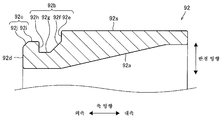
도 5는, 제2 외륜 부재(92)의 단면도이다. 제2 외륜 부재(92)의 외주면(92s) 중 외측에는, 홈(92b)이 형성된다. 홈(92b)은 둘레 방향으로 환상으로 연장된다. 홈(92b)은, 축 방향에서, 제2 외륜 부재(92)가 제1 외륜 부재(91)와 접촉하는 면(92d)으로부터 약 0.2 내지 2 cm의 거리를 두고 형성된다.5 is a sectional view of the second
제2 외륜 부재(92) 중, 홈(92b)보다 외측에는, 돌출부(92c)가 제공된다. 돌출부(92c)는, 홈(92b)으로부터 반경 방향에서 외측으로 돌출한다.Outwardly of the second
홈(92b)은, 면(92e), 면(92f), 면(92g) 및 면(92h)을 포함한다. 또한, 돌출부(92c)는, 면(92i) 및 면(92j)을 포함한다. 돌출부(92c)의 면(92i) 및 면(92j)은 축방향 중심부를 향하는 단부면을 형성한다.The
면(92e)은, 외주면(92s)과 연속하고 있다. 면(92e)은, 반경 방향에 대하여 실질적으로 평행한 환상 면이다.The
면(92f)은, 면(92e)의 외측에, 면(92e)과 연속하여 형성된다. 면(92f)은, 축 방향에 대하여 경사져 있다. 또한, 면(92f)은, 반경 방향에 대하여도 경사져 있다. 면(92f)은, 전체로서, 외측으로부터 내측을 향해서 직경이 증가하는 측면도에 있어서의 원뿔대 형상을 갖는 면을 형성한다.The
면(92g)은, 면(92f)의 외측에, 면(92f)과 연속하여 형성된다. 면(92g)은, 축 방향에 대하여 실질적으로 평행하다. 면(92g)은, 전체로서, 원통형 면을 형성한다.The
면(92h)은, 면(92g)의 외측에, 면(92g)과 연속하여 형성된다. 면(92h)은, 돌출부(92c)와 연속하고 있다. 면(92h)은, 반경 방향에 대하여 실질적으로 평행한 환상 면이다. 면(92h)은, 결합 링(13)의 면(15a)과 계합된다.The
면(92i)은, 홈(92b)의 면(92h)과 연속한다. 면(92i)은, 축 방향에 대하여 실질적으로 평행하다. 면(92i)은, 전체로서, 원통형 면을 형성한다. 면(92i)은, 외주면(92s)보다 축심(L1)(도 5에는 도시하지 않음)에 가깝다.The
면(92j)은, 돌출부(92c)의 축방향 중심부를 향한 단부면 중, 축심(L1)으로부터 가장 먼 부분을 형성한다. 면(92j)은, 면(92i)의 외측에, 면(92i)과 연속하여 형성된다. 또한, 면(92j)은, 제2 외륜 부재(92)가 제1 외륜 부재(91)와 접촉하는 면(92d)과 연속한다. 면(92j)은, 축 방향에 대하여 경사져 있다. 또한, 면(92j)은, 반경 방향에 대하여도 경사져 있다. 면(92j)은, 전체로서, 외측으로부터 내측을 향해서 직경이 증가하는 측면도에 있어서의 원뿔대 형상을 갖는 면을 형성하고 있다.The
제2 외륜 부재(92)의 돌출부(92c)를 형성하는 면(92i) 및 면(92j)에는 연마가 행해지지 않는다. 즉, 제2 외륜 부재(92)의 돌출부(92c)를 형성하는 면(92i) 및 면(92j)에는, 연마면이 포함되지 않는다.The
제1 외륜 부재(91) 및 제2 외륜 부재(92) 각각은 단조 및 선삭에 의해 형성된다. 형성 후, 제1 외륜 부재(91) 및 제2 외륜 부재(92)의 궤도면(31, 32)에 대하여 연마가 행해진다. 이때, 제1 외륜 부재(91)의 돌출부(91c)를 형성하는 면(91i, 91j), 및 제2 외륜 부재(92)의 돌출부(92c)를 형성하는 면(92i, 92j)에는 연마가 행해지지 않는다.Each of the first
이하, 결합 링(13)에 의해 제1 외륜 부재(91) 및 제2 외륜 부재(92)가 서로 고정되는 부분의 구조에 대해서 상세하게 설명한다. 도 6은, 제1 외륜 부재(91), 제2 외륜 부재(92) 및 결합 링(13)이 함께 끼워맞춰진 상태를 도시하는 단면도이다.Hereinafter, the structure of the portion where the first
제1 외륜 부재(91), 제2 외륜 부재(92) 및 결합 링(13)이 끼워맞춰진 상태에서, 도 6에 도시하는 바와 같이, 결합 링(13)의 갈고리(14)는 홈(91b)에 끼워맞춰지며, 갈고리(15)는 홈(92b)에 끼워맞춰진다. 이때, 갈고리(14)의 면(14a)은 제1 외륜 부재(91)의 면(91h)에 대향하며, 동시에 갈고리(15)의 면(15a)은 제2 외륜 부재(92)의 면(92h)에 대향한다. 그리고, 축 방향에서 갈고리(14)와 갈고리(15) 사이에 형성되는 공간에 돌출부(91c, 92c)가 끼워맞춰진다. 이에 의해, 제1 외륜 부재(91)와 제2 외륜 부재(92) 사이의 축 방향의 상대적인 이동이 규제된다.6, the
도 6에 도시된 구조에 대해서 상세하게 설명한다. 제1 외륜 부재(91)의 면(91e)은 결합 링(13)의 면(13a)과 대향한다. 면(91i)은, 결합 링(13)의 내주면(13c)과 대향한다. 홈(91b)에서는, 면(91f)이 갈고리(14)의 면(14c)과 대향한다. 면(91g)은 갈고리(14)의 면(14b)과 대향한다. 면(91h)은 갈고리(14)의 면(14a)과 대향한다.The structure shown in Fig. 6 will be described in detail. The
또한, 제1 외륜 부재(92)의 면(92e)은 결합 링(13)의 면(13b)과 대향한다. 면(92i)은 결합 링(13)의 내주면(13c)과 대향한다. 홈(92b)에서는, 면(92f)은 갈고리(15)의 면(15c)과 대향한다. 면(92g)은 갈고리(15)의 면(15b)과 대향한다. 면(92h)은 갈고리(15)의 면(15a)과 대향한다.The
또한, 제1 외륜 부재(91)의 면(91j)과, 제2 외륜 부재(92)의 면(92j)과, 결합 링(13)의 내주면(13c) 사이에는 공간이 형성된다.A space is formed between the
면(91i)의 외경은 면(13c)의 내경보다 약간 크다. 즉, 서로 대향하는 한 쌍의 면(91i, 13c)은 억지 끼워맞춤 방식으로 끼워맞춰지도록 설계된다. 한편, 대향하는 면(91e, 13a), 대향하는 면(91f, 14c), 대향하는 면(91g, 14b), 및 대향하는 면(91h, 14a)은 헐거운 끼워맞춤 방식으로 끼워맞춰지도록 설계된다.The outer diameter of the surface 91i is slightly larger than the inner diameter of the
또한, 면(92i)의 외경은 면(13c)의 내경보다 약간 크다. 즉, 서로 대향하는 한 쌍의 면(92i, 13c)은 억지 끼워맞춤 방식으로 끼워맞춰지도록 설계된다. 한편, 대향하는 면(92e, 13b), 대향하는 면(92f, 15c), 대향하는 면(92g, 15b), 및 대향하는 면(92h, 15a)은 헐거운 끼워맞춤 방식으로 끼워맞춰지도록 설계된다.The outer diameter of the
대향하는 한 쌍의 면(91i, 13c), 및 대향하는 한 쌍의 면(92i, 13c)이 억지 끼워맞춤 방식으로 끼워맞춰지도록 설계되는 것은 본 발명의 필수적인 구성은 아니다. 예를 들어, 대향하는 한 쌍의 면(91i, 13c), 및 대향하는 한 쌍의 면(92i, 13c)은 헐거운 끼워맞춤 방식으로 끼워맞춰지도록 설계될 수 있다. 이 경우에도, 제1 외륜 부재(91) 및 제2 외륜 부재(92)가 각각 외주면에 홈(91b) 및 홈(92b)을 포함하고 있는 한은, 제1 외륜 부재(91) 및 제2 외륜 부재(92)의 외주면 중 결합 링과 끼워맞춰지는 부분을 연마하지 않고, 결합 링(13)에 의해 제1 외륜 부재(91) 및 제2 외륜 부재(92)를 서로 고정한다.It is not an essential constitution of the present invention that the pair of opposing
결합 링(13)은, 압입 방식에 의해 제1 외륜 부재(91) 및 제2 외륜 부재(92)의 외주면(91s, 92s)에 부착될 수 있다. 이에 의해, 제1 외륜 부재(91)와 제2 외륜 부재(92) 사이의 축 방향의 상대적인 이동이 규제된다.The engaging
(제1 실시형태의 효과)(Effects of First Embodiment)
특허 문헌 1(DE 102010017964A1; 명세서)에 개시된 베어링 장치와 같이, 외륜 부재의 내주면을 결합 링에 의해 서로에 대해 고정하는 경우에는, 결합 링을 외륜 부재에 압입할 필요가 있어, 외륜 부재의 내경 치수와 결합 링의 외주면의 치수에 높은 정밀도가 요구되므로, 외륜 부재 중 결합 링과 끼워맞춰지는 부분을 연마할 필요가 있다. 따라서, 외륜 부재 중 결합 링과 끼워맞춰지는 부분은 연마면을 포함한다.In the case of fixing the inner circumferential surfaces of the outer ring members to each other with the coupling ring like the bearing device disclosed in Patent Document 1 (DE 102010017964A1; Specification), it is necessary to press the coupling ring into the outer ring member, And the outer peripheral surface of the coupling ring are required to be highly precise, it is necessary to polish the portion of the outer ring member which is fitted to the coupling ring. Therefore, the portion of the outer ring member which is fitted to the coupling ring includes the polishing surface.
그러나, 제1 실시형태의 원추형 롤러 베어링(3)에 따르면, 제1 외륜 부재(91) 및 제2 외륜 부재(92)는 각각 외주면에 홈(91b) 및 홈(92b)을 포함하고, 결합 링(13)은 홈(91b) 및 홈(92b)에 대응하는 갈고리(14, 15)를 포함하고, 홈(91b) 및 홈(92b)은 각각 갈고리(14, 15)에 끼워맞춰지므로, 제1 외륜 부재(91) 및 제2 외륜 부재(92)는 고정될 수 있다.However, according to the
결합 링(13)의 갈고리(14, 15)는, 억지 끼워맞춤 방식으로 홈(91b, 92b)에 고정될 수 있거나, 헐거운 끼워맞춤 방식으로 홈(91b, 92b)에 고정될 수 있기 때문에, 결합 링(13)과 끼워맞춰지는 부분은 높은 정밀도로 가공되는 것이 요구되지 않고, 돌출부(91c, 92c)의 연마가 불필요하다. 따라서, 제1 외륜 부재(91) 및 제2 외륜 부재(92)의 돌출부(91c, 92c)는 연마면을 포함하지 않도록 구성될 수 있다.The
제1 실시형태의 원추형 롤러 베어링(3) 중, 결합 링(13)의 갈고리(14)의 외측은 반경 방향 및 축 방향의 양쪽으로 경사진 면(14c)을 포함한다. 그로 인해, 갈고리(14)가 면(14c)을 포함하지 않는 경우와 비교하여, 작은 힘으로 결합 링(13)을 제1 외륜 부재(91)에 삽입할 수 있다. 갈고리(14)는 반경 방향 및 축 방향의 양쪽으로 경사진 면(14c)을 포함하므로, 갈고리(14)의 외측의 코너 부분은 제1 외륜 부재(91)의 면과 접촉하는 것이 방지된다.The outer side of the
마찬가지로, 결합 링(13)의 갈고리(15)의 내측은, 반경 방향 및 축 방향의 양쪽으로 경사진 면(15c)을 포함한다. 그로 인해, 갈고리(15)가 면(15c)을 포함하지 않는 경우와 비교하여, 작은 힘으로 결합 링(13)을 제2 외륜 부재(92)에 삽입할 수 있다. 갈고리(15)는 반경 방향 및 축 방향의 양쪽으로 경사진 면(15c)을 포함하기 때문에, 갈고리(15)의 내측의 코너 부분은 제2 외륜 부재(92)의 면에 접촉하는 것이 방지된다.Likewise, the inside of the
또한, 제1 외륜 부재(91)의 돌출부(91c)의 내측의 코너 부분은 반경 방향 및 축 방향의 양쪽으로 경사진 면(91j)을 포함한다. 그로 인해, 제1 외륜 부재(91)가 면(91j)을 포함하지 않는 경우와 비교하여, 작은 힘으로 결합 링(13)을 제1 외륜 부재(91)에 삽입할 수 있다. 돌출부(91c)는 반경 방향 및 축 방향의 양쪽으로 경사진 면(91j)을 포함하기 때문에, 돌출부(91c)의 내측의 코너 부분은 결합 링(13)의 내주면(13c)에 접촉하는 것이 방지된다.The inner corner portion of the protruding
마찬가지로, 제2 외륜 부재(92)의 돌출부(92c)의 외측의 코너 부분은, 반경 방향 및 축 방향의 양쪽으로 경사진 면(92j)을 포함한다. 그로 인해, 제2 외륜 부재(92)가 면(92j)을 포함하지 않는 경우와 비교하여, 작은 힘으로 결합 링(13)을 제2 외륜 부재(92)에 삽입할 수 있다. 돌출부(92c)는 반경 방향 및 축 방향의 양쪽으로 경사진 면(92j)을 포함하기 때문에, 돌출부(92c)의 외측의 코너 부분은 결합 링(13)의 내주면(13c)에 접촉하는 것이 방지된다.Likewise, the outer corner portion of the
상술한 바와 같이, 갈고리(14)의 외측의 코너 부분 또는 갈고리(15)의 내측의 코너 부분은 제1 외륜 부재(91) 및 제2 외륜 부재(92)에 접촉하는 것이 방지되거나, 돌출부(91c)의 내측의 코너 부분 또는 돌출부(92c)의 외측의 코너 부분은 결합 링(13)의 내주면(13c)에 접촉하는 것이 방지된다. 그로 인해, 결합 링(13)의 수지가 깎여서 원추형 롤러 베어링(3) 내에 잔류물이 남거나, 큰 힘에 의해 결합 링(13)을 형성하는 수지가 열화되는 것이 방지된다.The outer corner portions of the
<다른 실시형태><Other Embodiments>
제1 실시형태에서는, 제1 외륜 부재(91)의 홈(91b)을 형성하는 면은, 축 방향 및 반경 방향의 양쪽으로 경사진 면(91f)을 포함하지만, 도 7에 도시하는 바와 같이, 면(91f)은 필수적인 구성이 아니다. 마찬가지로, 제2 외륜 부재(92)의 홈(92b)을 형성하는 면은, 축 방향 및 반경 방향의 양쪽으로 경사진 면(92f)을 포함하지만, 도 7에 도시하는 바와 같이, 면(92f)은 필수적인 구성이 아니다. 이 경우, 면(91e), 면(91g) 및 면(14c)의 사이에 환상 공간이 형성된다. 이 경우에도, 제1 실시형태와 마찬가지의 효과를 얻을 수 있다.In the first embodiment, the surface defining the
제1 실시형태에서는, (1) 갈고리(14)의 외측이 반경 방향 및 축 방향의 양쪽으로 경사진 면(14c)을 포함하고, 갈고리(15)의 내측이 반경 방향 및 축 방향의 양쪽으로 경사진 면(15c)을 포함하고, (2) 돌출부(91c)의 내측의 코너 부분이 반경 방향 및 축 방향의 양쪽으로 경사진 면(91j)을 포함하며, 돌출부(92c)의 외측의 코너 부분이 반경 방향 및 축 방향의 양쪽으로 경사진 면(92j)을 포함하는 구성에 대해서 설명하였다. 그러나, 본 발명에 따르면, (1) 또는 (2)의 어느 하나에 의해 본 발명의 과제를 해결할 수 있다.(1) In the first embodiment, the outer side of the
예를 들어, 도 8에 도시하는 바와 같이, 갈고리(14)의 외측은 반경 방향 및 축 방향의 양쪽으로 경사진 면(14c)을 포함하고, 갈고리(15)의 내측은 반경 방향 및 축 방향의 양쪽으로 경사진 면(15c)을 포함하는 반면, 돌출부(91c, 92c)는 경사진 면을 포함하지 않을 수 있다.8, the outside of the
또한, 도 9에 도시하는 바와 같이, 돌출부(91c)의 내측의 코너 부분은, 반경 방향 및 축 방향의 양쪽으로 경사진 면(91j)을 포함하고, 돌출부(92c)의 외측의 코너 부분은 반경 방향 및 축 방향의 양쪽으로 경사진 면(92j)을 포함하는 반면, 갈고리(14, 15)는 경사진 면을 포함하지 않을 수 있다.9, the inner corner portion of the protruding
제1 실시형태 및 변형예에서 설명한 바와 같이, 제1 외륜 부재(91)와 제2 외륜 부재(92)가 경사진 면을 포함하는 것은 필수적인 것은 아니다. 제1 외륜 부재(91) 및 제2 외륜 부재(92)가 각각 그 외주면에 홈(91b) 및 홈(92b)을 포함하는 한은, 제1 외륜 부재(91) 및 제2 외륜 부재(92)의 외주면을 연마하지 않고, 결합 링(13)에 의해 제1 외륜 부재(91) 및 제2 외륜 부재(92)를 고정할 수 있다.It is not essential that the first
본 실시형태에서는, 제1 외륜 부재(91)와 제2 외륜 부재(92)를 결합하는 결합 링(13)이 외륜(9)의 외주면에 끼워맞춰지는 경우에 대해서 설명했지만, 도 10에 도시하는 외륜(9D)과 같이, 제1 외륜 부재(91D)와 제2 외륜 부재(92D)는 내주면에서 결합 링(13D)에 의해 서로 고정될 수 있다. 제1 외륜 부재(91D), 제2 외륜 부재(92D) 및 결합 링(13D)의 결합 부분에서, 각각의 구조는, 상술한 제1 실시형태 또는 변형예의 구성과, 상측 및 하측이 반대로 된 것을 제외하고 동일하다.Although the engaging
이하에서는 결합 링(13)의 구조의 변형예에 대해서 설명한다. 도 11 및 도 12는 변형예에 따른 결합 링(13E, 13F)을 도시하는 단면도이다.Modifications of the structure of the
결합 링(13)은, 외측 및 내측의 단부면에, 반경 방향으로 서로 실질적으로 평행한 면(13a, 13b)을 포함하지 않을 수 있다. 예를 들어, 도 11에 도시한 바와 같이, 결합 링(13E)의 외측의 단부면은 모두 축 방향 및 반경 방향의 양쪽으로 경사진 면(14c)으로 형성된다. 마찬가지로, 결합 링(13E)의 내측의 단부면은 모두 축 방향 및 반경 방향의 양쪽으로 경사진 면(15c)으로 형성될 수 있다.The
또한, 결합 링(13)의 갈고리(14, 15)는, 축 방향으로 서로 실질적으로 평행한 면(14b, 15b)을 포함하지 않을 수 있다. 예를 들어, 도 12에 도시하는 바와 같이, 결합 링(13F)의 갈고리(14F)는 면(14a) 및 면(14c) 만을 포함한다. 마찬가지로, 갈고리(15F)는 면(15a) 및 면(15c) 만을 포함한다.The
갈고리(14)의 축 방향 외측을 향한 단부면에서, 적어도 반경 방향에서 가장 축심에 가까운 부분이, 축 방향 및 반경 방향으로 경사진 면일 수 있다. 예를 들어, 갈고리(14)의 축 방향 외측을 향하는 단부면은, 경사진 면(14c), 및 반경 방향에서 면(14c)의 외측에 연속하고 반경 방향에 평행한 면을 포함할 수 있다. 이는 갈고리(15)에도 적용된다.At the end surface facing the axially outward side of the
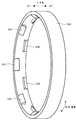
상술한 실시형태에서는, 결합 링(13)의 내주면에 환상 갈고리(14, 15)가 형성되어 있는 경우를 설명했지만, 갈고리(14, 15)의 형상은 이것에 한정되지 않는다. 예를 들어, 도 13에 도시하는 바와 같이, 결합 링(13G)의 복수의 갈고리(14G, 15G)는 둘레 방향에서 서로 이격되도록 형성될 수 있다. 이 경우에는, 갈고리(14G, 15G)는 둘레 방향으로 비연속적으로 형성되고, 따라서 제1 외륜 부재(91) 및 제2 외륜 부재(92)에 결합 링이 끼워맞춰질 때 압입력이 저감될 수 있다.The
또한, 도 14에 도시하는 바와 같이, 결합 링(13H)에서, 둘레 방향으로 서로 이격되도록 형성된 복수의 갈고리(14H, 15H)가, 축 방향에서 볼 때 서로 겹치지 않도록 배치될 수 있다. 도 14에 도시하는 결합 링(13H)을 사출 성형하는 경우에는, 축 방향에서 갈고리(14H, 15H) 사이에 채워진 수지를 제거하는 가공을 행할 필요가 없다. 따라서, 높은 수율로 결합 링(13H)을 제조할 수 있다.Further, as shown in Fig. 14, in the
상술한 실시형태에서는, 결합 링(13)은 무단 링 형상으로 구성되지만, 다른 형상으로 구성될 수 있다. 예를 들어, 도 15에 도시하는 바와 같이, 결합 링(13I)의 일부가 개환 형상을 가질 수 있다.In the above-described embodiment, the
상술한 제1 및 제2 실시형태에서, 전동 요소(11) 중 축 방향의 중심부에 가까운 저부(11a)는 축 방향의 양 단부에 가까운 저부(11b)보다 반경 방향에서 축심(L1)에 가깝게 배치되지만, 본 발명은 특별히 이것으로 한정되지 않는다. 전동 요소(11) 중 축 방향의 중심부에 가까운 저부(11a)는, 축 방향의 양 단부에 가까운 저부(11b)보다 반경 방향에서 축심(L1)으로부터 멀리 배치될 수 있다.In the first and second embodiments described above, the
상술한 제1 및 제2 실시형태에서는, 허브 유닛(100)의 외측은, 제1 외륜 부재(91) 및 제2 외륜 부재(92) 중, 제1 외륜 부재(91)이며, 내측은 제2 외륜 부재(92)이지만, 이는 일례이다. 허브 유닛(100)은 자유롭게 배치되며, 외측 및 내측은 반대일 수 있다.In the first and second embodiments described above, the outer side of the
제1 및 제2 실시형태에서는, 원추형 롤러 베어링(3)에 대해서 설명했지만, 베어링 장치가 복열로 배치된 전동 요소를 갖는 한은, 본 발명은 다른 유형의 베어링 장치에도 적용될 수 있다. 예를 들어, 본 발명은 전동 요소가 볼 전동 요소인 베어링 장치에 적용될 수 있다.Although the
상술한 실시형태는 모두 본 발명의 기술적인 내용을 명확하게 하기 위한 것에 지나지 않는다. 본 발명은 이러한 특정 예로 한정되는 것으로 해석되어서는 않되고 광범위하게 해석되어야 하며, 첨부된 청구범위에 설명된 본 발명의 사상 및 범위 내에서 본 발명의 다양한 변형이 이루어질 수 있다.The above-described embodiments are merely for the purpose of clarifying the technical contents of the present invention. The present invention is not to be construed as being limited to these specific examples but should be construed broadly and that various modifications of the present invention can be made within the spirit and scope of the present invention as set forth in the appended claims.
본 출원은 그 전체 내용이 참조로 본원에 통합되는 2015년 12월 25일에 출원된 일본 특허 출원 제2015-2253053호에 기초하여 그 우선권의 이점을 청구한다.This application claims benefit of priority based on Japanese Patent Application No. 2015-2253053, filed December 25, 2015, the entire contents of which are incorporated herein by reference.
3: 원추형 롤러 베어링(베어링 장치)
9: 외륜
91: 제1 외륜 부재
91a: 궤도면
91b: 홈(제1 홈)
91c: 돌출부(제1 돌출부)
91j: 경사진 면
92: 제2 외륜 부재
92a: 궤도면
92b: 홈(제2 홈)
92c: 돌출부(제2 돌출부)
92j: 경사진 면
10: 내륜
10a: 궤도면
11: 복수의 전동 요소
13: 결합 링
14: 갈고리(제1 갈고리)
14c: 경사진 면
15: 갈고리(제2 갈고리)
15c: 경사진 면3: Conical roller bearing (bearing device)
9: Outer ring
91: first outer ring member
91a: orbital plane
91b: groove (first groove)
91c: projecting portion (first projecting portion)
91j: inclined surface
92: second outer ring member
92a: orbital plane
92b: groove (second groove)
92c: projecting portion (second projecting portion)
92j: inclined surface
10: Inner ring
10a: orbital plane
11: plural electromotive elements
13: Coupling ring
14: hook (first hook)
14c: inclined side
15: The hook (second hook)
15c: inclined side
Claims (4)
각각의 내주면에 궤도면을 포함하고, 축 방향으로 서로 접하도록 배치되는 제1 외륜 부재 및 제2 외륜 부재;
상기 제1 외륜 부재 및 상기 제2 외륜 부재를 서로 고정하는 결합 링;
외주면에 2열의 궤도면이 형성된 내륜; 및
상기 제1 외륜 부재의 상기 궤도면과 상기 내륜의 2열의 궤도면 중 하나 사이에 형성되는 공간, 및 상기 제2 외륜 부재의 상기 궤도면과 상기 내륜의 2열의 궤도면 중 다른 하나 사이에 형성되는 공간에 배치되는 복수의 전동 요소를 포함하고,
상기 제1 외륜 부재는,
외주면에서 둘레 방향으로 연장되는 제1 홈, 및
상기 제1 홈보다 상기 제2 외륜 부재에 가까운 위치에서, 반경 방향 외측으로 돌출하도록 환상으로 형성되는 제1 돌출부를 포함하고,
상기 제2 외륜 부재는,
외주면에서 둘레 방향으로 연장되는 제2 홈, 및
상기 제2 홈보다 상기 제1 외륜 부재에 가까운 위치에서 반경 방향 외측으로 돌출하도록 환상으로 형성되는 제2 돌출부를 포함하고,
상기 결합 링은,
상기 제1 홈을 향해서 돌출하는 제1 갈고리, 및
상기 제2 홈을 향해서 돌출하는 제2 갈고리를 포함하며,
상기 제1 외륜 부재의 상기 제1 돌출부를 형성하는 면 및 상기 제2 외륜 부재의 상기 제2 돌출부를 형성하는 면은 연마면을 포함하지 않는 베어링 장치.A bearing device comprising:
A first outer ring member and a second outer ring member including raceways on respective inner circumferential surfaces and arranged to be in contact with each other in the axial direction;
A coupling ring for fixing the first outer ring member and the second outer ring member to each other;
An inner ring having two rows of raceways formed on its outer circumferential surface; And
A space formed between the raceway surface of the first outer ring member and one of two rows of raceway surfaces of the inner ring and a space formed between the raceway surface of the second outer ring member and another one of the two rows of raceway surfaces of the inner ring A plurality of electromotive elements disposed in the space,
Wherein the first outer-
A first groove extending in the peripheral direction on the outer peripheral surface, and
And a first projection projecting radially outward at a position closer to the second outer ring member than the first groove,
Wherein the second outer-
A second groove extending in the peripheral direction on the outer peripheral surface, and
And a second protrusion formed in an annular shape so as to project radially outward at a position closer to the first outer ring member than the second groove,
The coupling ring
A first hook that protrudes toward the first groove, and
And a second hook that protrudes toward the second groove,
Wherein the surface forming the first projection of the first outer ring member and the surface forming the second projection of the second outer ring member do not include the polishing surface.
상기 제1 갈고리를 형성하는 면에서, 축 방향 외측을 향하는 단부면 중 적어도 반경 방향에서 축심에 가장 가까운 부분은, 축 방향의 중심부로부터 외측을 향해서 직경이 커지는 경사진 면이며,
상기 제2 갈고리를 형성하는 면에서, 축 방향 외측을 향한 단부면 중 적어도 반경 방향에서 축심에 가장 가까운 부분은, 축 방향의 중심부로부터 외측을 향해서 직경이 커지는 경사진 면인 베어링 장치.The method according to claim 1,
A portion closest to the axial center in at least the radial direction of the end surface facing the axially outward side of the surface forming the first claw is a tilted surface whose diameter increases outward from the central portion in the axial direction,
Wherein the portion closest to the axial center in at least the radial direction of the end surface facing the axially outward side of the surface forming the second claw is a tilted surface whose diameter increases outward from the central portion in the axial direction.
상기 제1 돌출부를 형성하는 면에서, 축 방향 중심부를 향하는 단부면 중 적어도 반경 방향에서 축심에 대해 가장 먼 부분은, 축 방향의 중심부로부터 외측을 향해서 직경이 커지는 경사진 면이며,
상기 제2 돌출부를 형성하는 면에서, 축 방향 중심부를 향하는 단부면 중 적어도 반경 방향에서 축심에 대해 가장 먼 부분은, 축 방향의 중심부로부터 외측을 향해서 직경이 커지는 경사진 면인 베어링 장치.3. The method according to claim 1 or 2,
The portion farthest from the axial center in the radial direction of the end surface facing the axial center portion on the surface forming the first projection is a tilted surface having a larger diameter from the central portion in the axial direction toward the outer side,
Wherein a portion of the end surface facing the axial center portion at least in the radial direction with respect to the axial center on the surface forming the second projection is a tapered surface whose diameter increases outward from a central portion in the axial direction.
상기 결합 링의 내주면과 상기 제1 돌출부의 반경 방향 외측을 향하는 면 사이의 반경 방향에서의 거리는, 상기 제1 홈과 상기 제1 갈고리 사이에 형성되는 간극의 두께보다 작으며,
상기 결합 링의 내주면과 상기 제2 돌출부의 반경 방향 외측을 향하는 면 사이의 반경 방향에서의 거리는, 상기 제2 홈과 상기 제2 갈고리 사이에 형성되는 간극의 두께보다 작은 베어링 장치.4. The method according to any one of claims 1 to 3,
The distance in the radial direction between the inner circumferential surface of the engaging ring and the surface facing the radially outward side of the first projecting portion is smaller than the thickness of the gap formed between the first groove and the first engaging portion,
Wherein the radial distance between the inner peripheral surface of the engaging ring and the surface facing the radially outward side of the second projection is smaller than the thickness of the gap formed between the second recess and the second recess.
Applications Claiming Priority (3)
| Application Number | Priority Date | Filing Date | Title |
|---|---|---|---|
| JPJP-P-2015-253053 | 2015-12-25 | ||
| JP2015253053A JP6720525B2 (en) | 2015-12-25 | 2015-12-25 | Bearing device |
| PCT/JP2016/088297 WO2017110978A1 (en) | 2015-12-25 | 2016-12-22 | Bearing device |
Publications (1)
| Publication Number | Publication Date |
|---|---|
| KR20180098263A true KR20180098263A (en) | 2018-09-03 |
Family
ID=59090879
Family Applications (1)
| Application Number | Title | Priority Date | Filing Date |
|---|---|---|---|
| KR1020187017806A Ceased KR20180098263A (en) | 2015-12-25 | 2016-12-22 | Bearing device |
Country Status (6)
| Country | Link |
|---|---|
| US (1) | US10641323B2 (en) |
| JP (1) | JP6720525B2 (en) |
| KR (1) | KR20180098263A (en) |
| CN (1) | CN108431438A (en) |
| DE (1) | DE112016006054T5 (en) |
| WO (1) | WO2017110978A1 (en) |
Cited By (1)
| Publication number | Priority date | Publication date | Assignee | Title |
|---|---|---|---|---|
| WO2024158067A1 (en) * | 2023-01-26 | 2024-08-02 | 주식회사 일진글로벌 | Wheel bearing with improved inner ring structure |
Families Citing this family (4)
| Publication number | Priority date | Publication date | Assignee | Title |
|---|---|---|---|---|
| DE202019101636U1 (en) | 2019-03-21 | 2019-08-13 | Liebherr-Components Biberach Gmbh | Seal for slewing bearings |
| US11187271B2 (en) * | 2019-07-04 | 2021-11-30 | Aktiebolaget Skf | Polymer joining ring for a bearing assembly |
| CN114320806A (en) * | 2022-01-06 | 2022-04-12 | 佛山市液斯源液压制造有限公司 | Hydraulic pump shell and machine core using same |
| DE102023120361A1 (en) * | 2023-08-01 | 2025-02-06 | Schaeffler Technologies AG & Co. KG | Double-row roller bearing |
Citations (1)
| Publication number | Priority date | Publication date | Assignee | Title |
|---|---|---|---|---|
| DE102010017964A1 (en) | 2010-04-23 | 2011-10-27 | Aktiebolaget Skf | Roller bearing i.e. double row roller bearing, for use in standard machinery, has connecting and sealing rings arranged in axial end regions, and press fit provided between surface area of recesses and connecting and sealing rings |
Family Cites Families (28)
| Publication number | Priority date | Publication date | Assignee | Title |
|---|---|---|---|---|
| US1379945A (en) * | 1919-12-18 | 1921-05-31 | Waldemar H Teetsow | Ball-bearing |
| US1908474A (en) * | 1930-06-12 | 1933-05-09 | Hessbright Mfg Company | Connected bearing |
| US2075280A (en) * | 1934-11-19 | 1937-03-30 | Gen Motors Corp | Bearing |
| SE338907B (en) * | 1970-05-08 | 1971-09-20 | Skfind Handel En Ontwikkeling | |
| JPS5223621B2 (en) * | 1973-09-28 | 1977-06-25 | ||
| JPS5724988Y2 (en) * | 1973-10-06 | 1982-05-31 | ||
| JPS5650172Y2 (en) * | 1976-10-05 | 1981-11-24 | ||
| DE3536697A1 (en) * | 1985-10-15 | 1987-04-16 | Skf Gmbh | SUPPORTING BODY OF A ROLLER BEARING |
| JPH0547851Y2 (en) * | 1986-03-29 | 1993-12-17 | ||
| FR2597177B1 (en) * | 1986-04-14 | 1988-07-01 | Skf Cie Applic Mecanique | ROLLING BEARING HAVING TWO ROWS OF ROLLING ELEMENTS PROVIDED WITH A RETAINING PIECE FOR THE BEARING RINGS, RETAINING PIECE THAT CAN BE USED FOR THIS PURPOSE AND METHOD FOR ASSEMBLING SUCH A BEARING |
| DE3817175A1 (en) * | 1988-05-20 | 1989-11-30 | Skf Gmbh | Rolling bearing unit for antilocking system |
| SE9301501D0 (en) * | 1993-05-12 | 1993-05-03 | CONNECTING RING | |
| DE9406691U1 (en) * | 1994-04-21 | 1994-06-09 | Skf Gmbh, 97421 Schweinfurt | Device for connecting bearing rings |
| JP2001140868A (en) * | 1999-11-11 | 2001-05-22 | Ntn Corp | Double-row rolling bearing |
| JP2004360723A (en) * | 2003-06-02 | 2004-12-24 | Ntn Corp | Rolling bearing |
| JP2005214330A (en) * | 2004-01-30 | 2005-08-11 | Ntn Corp | Four-point contact ball bearing and manufacturing method thereof |
| US7121728B2 (en) * | 2004-08-04 | 2006-10-17 | Gunite Corporation | Seal for a bearing assembly |
| JP4211718B2 (en) * | 2004-09-29 | 2009-01-21 | 株式会社ジェイテクト | Machining method of raceway surface of outer ring of double row angular contact ball bearing |
| EP1853830A1 (en) * | 2005-03-02 | 2007-11-14 | The Timken Company | Bearing assembly with a seal-forming bore clip |
| JP2006312955A (en) * | 2005-05-06 | 2006-11-16 | Nsk Ltd | Rolling bearing |
| DE102006008731A1 (en) * | 2006-02-24 | 2007-08-30 | Schaeffler Kg | Slanted rolling bearing comprises a bearing outer ring with single rings connected together with play using a connecting element |
| US8485730B2 (en) * | 2008-03-27 | 2013-07-16 | Ntn Corporation | Rolling bearing |
| JP2010156455A (en) * | 2008-12-04 | 2010-07-15 | Jtekt Corp | Rolling bearing device |
| CN102245793B (en) * | 2008-12-12 | 2014-07-09 | 株式会社捷太格特 | Constituent member of bearing, process for production of same, and ball-and-roller bearing provided with the constituent member |
| JP2011027130A (en) | 2009-07-22 | 2011-02-10 | Ntn Corp | Bearing device for wheel |
| JP5682161B2 (en) * | 2009-08-10 | 2015-03-11 | 株式会社ジェイテクト | Manufacturing method of rolling sliding member |
| DE102013210523B4 (en) * | 2013-06-06 | 2024-04-18 | Aktiebolaget Skf | roller bearing |
| CN105065447A (en) | 2015-07-20 | 2015-11-18 | 山东凯美瑞轴承科技有限公司 | Double-half-outer-ring self-aligning roller bearing for stirring vehicle |
-
2015
- 2015-12-25 JP JP2015253053A patent/JP6720525B2/en active Active
-
2016
- 2016-12-22 DE DE112016006054.8T patent/DE112016006054T5/en not_active Withdrawn
- 2016-12-22 WO PCT/JP2016/088297 patent/WO2017110978A1/en not_active Ceased
- 2016-12-22 US US16/065,426 patent/US10641323B2/en not_active Expired - Fee Related
- 2016-12-22 CN CN201680076159.9A patent/CN108431438A/en active Pending
- 2016-12-22 KR KR1020187017806A patent/KR20180098263A/en not_active Ceased
Patent Citations (1)
| Publication number | Priority date | Publication date | Assignee | Title |
|---|---|---|---|---|
| DE102010017964A1 (en) | 2010-04-23 | 2011-10-27 | Aktiebolaget Skf | Roller bearing i.e. double row roller bearing, for use in standard machinery, has connecting and sealing rings arranged in axial end regions, and press fit provided between surface area of recesses and connecting and sealing rings |
Cited By (1)
| Publication number | Priority date | Publication date | Assignee | Title |
|---|---|---|---|---|
| WO2024158067A1 (en) * | 2023-01-26 | 2024-08-02 | 주식회사 일진글로벌 | Wheel bearing with improved inner ring structure |
Also Published As
| Publication number | Publication date |
|---|---|
| WO2017110978A1 (en) | 2017-06-29 |
| DE112016006054T5 (en) | 2018-09-06 |
| US20190024711A1 (en) | 2019-01-24 |
| JP2017116007A (en) | 2017-06-29 |
| CN108431438A (en) | 2018-08-21 |
| JP6720525B2 (en) | 2020-07-08 |
| US10641323B2 (en) | 2020-05-05 |
Similar Documents
| Publication | Publication Date | Title |
|---|---|---|
| KR20180098263A (en) | Bearing device | |
| CN103225683B (en) | Bearing regulator assembly | |
| US9145927B2 (en) | One-way clutch carrier assembly with bearing | |
| CN105605103A (en) | Hub-bearing unit | |
| CN103453013A (en) | Rolling bearing assembly device for steering column | |
| CN106089985A (en) | The assembling process of bearing unit hub flange | |
| US20130279837A1 (en) | Rolling bearing for power steering mechanism | |
| KR20180079333A (en) | Bearing device | |
| JP6342124B2 (en) | Roll bearing cage, roll bearing and automobile electric steering system | |
| WO2017164005A1 (en) | Double row bearing | |
| CN106838016B (en) | Seals for wheel bearing units | |
| CN105317853A (en) | Adapter, bearing unit, and wheel bearing with adapter | |
| JP2016130113A (en) | Semi-floating type wheel support device | |
| JP6511228B2 (en) | Bearings, in particular cages for bearings of automotive electrical steering systems | |
| JP2008249104A (en) | Roller bearing | |
| CN109790872B (en) | Three-pin bearing, constant velocity joint, and method for mounting a three-pin bearing | |
| CN205639341U (en) | Bearing device | |
| US9897151B2 (en) | One-way clutch | |
| JP2009083699A (en) | Wheel support device | |
| JP6515774B2 (en) | Double row tapered roller bearing unit for wheel support | |
| WO2017169976A1 (en) | Bearing with seal | |
| WO2015043629A1 (en) | Rolling bearing with pre-stressing member | |
| TWI712750B (en) | Roller bearing | |
| CN103085598A (en) | Wheel bearing device | |
| JP2005231475A (en) | Rolling bearing unit for wheel drive |
Legal Events
| Date | Code | Title | Description |
|---|---|---|---|
| PA0105 | International application |
Patent event date: 20180622 Patent event code: PA01051R01D Comment text: International Patent Application |
|
| PG1501 | Laying open of application | ||
| A201 | Request for examination | ||
| PA0201 | Request for examination |
Patent event code: PA02012R01D Patent event date: 20211028 Comment text: Request for Examination of Application |
|
| E902 | Notification of reason for refusal | ||
| PE0902 | Notice of grounds for rejection |
Comment text: Notification of reason for refusal Patent event date: 20230830 Patent event code: PE09021S01D |
|
| E601 | Decision to refuse application | ||
| PE0601 | Decision on rejection of patent |
Patent event date: 20231226 Comment text: Decision to Refuse Application Patent event code: PE06012S01D Patent event date: 20230830 Comment text: Notification of reason for refusal Patent event code: PE06011S01I |