KR20180098262A - Connecting device - Google Patents
Connecting device Download PDFInfo
- Publication number
- KR20180098262A KR20180098262A KR1020187017742A KR20187017742A KR20180098262A KR 20180098262 A KR20180098262 A KR 20180098262A KR 1020187017742 A KR1020187017742 A KR 1020187017742A KR 20187017742 A KR20187017742 A KR 20187017742A KR 20180098262 A KR20180098262 A KR 20180098262A
- Authority
- KR
- South Korea
- Prior art keywords
- connection device
- tube
- decoupling
- elements
- fluid chamber
- Prior art date
- Legal status (The legal status is an assumption and is not a legal conclusion. Google has not performed a legal analysis and makes no representation as to the accuracy of the status listed.)
- Abandoned
Links
Images


Classifications
-
- F—MECHANICAL ENGINEERING; LIGHTING; HEATING; WEAPONS; BLASTING
- F04—POSITIVE - DISPLACEMENT MACHINES FOR LIQUIDS; PUMPS FOR LIQUIDS OR ELASTIC FLUIDS
- F04D—NON-POSITIVE-DISPLACEMENT PUMPS
- F04D29/00—Details, component parts, or accessories
- F04D29/60—Mounting; Assembling; Disassembling
- F04D29/601—Mounting; Assembling; Disassembling specially adapted for elastic fluid pumps
-
- F—MECHANICAL ENGINEERING; LIGHTING; HEATING; WEAPONS; BLASTING
- F04—POSITIVE - DISPLACEMENT MACHINES FOR LIQUIDS; PUMPS FOR LIQUIDS OR ELASTIC FLUIDS
- F04D—NON-POSITIVE-DISPLACEMENT PUMPS
- F04D19/00—Axial-flow pumps
- F04D19/02—Multi-stage pumps
- F04D19/04—Multi-stage pumps specially adapted to the production of a high vacuum, e.g. molecular pumps
- F04D19/042—Turbomolecular vacuum pumps
-
- F—MECHANICAL ENGINEERING; LIGHTING; HEATING; WEAPONS; BLASTING
- F04—POSITIVE - DISPLACEMENT MACHINES FOR LIQUIDS; PUMPS FOR LIQUIDS OR ELASTIC FLUIDS
- F04D—NON-POSITIVE-DISPLACEMENT PUMPS
- F04D29/00—Details, component parts, or accessories
- F04D29/66—Combating cavitation, whirls, noise, vibration or the like; Balancing
- F04D29/661—Combating cavitation, whirls, noise, vibration or the like; Balancing especially adapted for elastic fluid pumps
- F04D29/668—Combating cavitation, whirls, noise, vibration or the like; Balancing especially adapted for elastic fluid pumps damping or preventing mechanical vibrations
-
- F—MECHANICAL ENGINEERING; LIGHTING; HEATING; WEAPONS; BLASTING
- F16—ENGINEERING ELEMENTS AND UNITS; GENERAL MEASURES FOR PRODUCING AND MAINTAINING EFFECTIVE FUNCTIONING OF MACHINES OR INSTALLATIONS; THERMAL INSULATION IN GENERAL
- F16L—PIPES; JOINTS OR FITTINGS FOR PIPES; SUPPORTS FOR PIPES, CABLES OR PROTECTIVE TUBING; MEANS FOR THERMAL INSULATION IN GENERAL
- F16L55/00—Devices or appurtenances for use in, or in connection with, pipes or pipe systems
- F16L55/04—Devices damping pulsations or vibrations in fluids
Landscapes
- Engineering & Computer Science (AREA)
- General Engineering & Computer Science (AREA)
- Mechanical Engineering (AREA)
- Compressors, Vaccum Pumps And Other Relevant Systems (AREA)
- Flanged Joints, Insulating Joints, And Other Joints (AREA)
- Pipe Accessories (AREA)
- Non-Positive Displacement Air Blowers (AREA)
- Quick-Acting Or Multi-Walled Pipe Joints (AREA)
Abstract
연결 장치는 진공 펌프에 연결될 수 있는 제 1 튜브 단부(10)를, 피진공배기 챔버에 연결될 수 있는 제 2 튜브 단부(12)에 연결하는 역할을 한다. 이 목적을 위해, 연결 요소(26)는 상기 진공 펌프를 상기 피진공배기 챔버에 유체적으로 연결하기 위한 튜브 요소(14)를 갖는다. 튜브 요소의 양 측면은 연결 요소(26)를 거쳐서 각각의 튜브 단부(10, 12)에 연결된다. 본 출원에 있어서, 2 개의 연결 요소(26) 중 적어도 하나는 토크만을 전용으로 전달하도록 구성된다. 게다가, 토크만을 전용으로 전달하도록 구성된 적어도 하나의 연결 요소(26)를 대응하는 튜브 단부(10, 12)로부터 기계적으로 디커플링시키기 위해 디커플링 요소(36)가 제공된다. The connecting device serves to connect the first tube end 10, which can be connected to the vacuum pump, to the second tube end 12 which can be connected to the evacuated exhaust chamber. For this purpose, the coupling element 26 has a tube element 14 for fluidly connecting the vacuum pump to the evacuated evacuation chamber. Both sides of the tube element are connected to the respective tube ends 10, 12 via a connecting element 26. In the present application, at least one of the two connecting elements 26 is configured to transmit torque only. In addition, a decoupling element 36 is provided for mechanically decoupling at least one connecting element 26 configured to transmit only the torque exclusively from the corresponding tube end 10,12.
Description
본 개시는 진공 펌프에 연결되도록 구성된 제 1 튜브 단부를, 진공 챔버에 연결되도록 구성된 제 2 튜브 단부에 연결하기 위한 연결 장치에 관한 것이다.The present disclosure relates to a connection device for connecting a first tube end configured to be connected to a vacuum pump to a second tube end configured to be connected to a vacuum chamber.
터보 분자 펌프와 같은 진공 펌프를 피진공배기 챔버(a chamber to be evacuated)에 연결할 때, 진공 펌프는 특히 회전자의 회전으로 인해 발생하는 진동을 피진공배기 챔버로 전달하는 문제점이 발생한다. 이는 피진공배기 챔버에서 또는 피진공배기 챔버에 연결된 장치에서 수행되는 공정 또는 측정에 영향을 줄 수도 있다. 예를 들어, 전자 현미경은 진동에 매우 민감하다.When a vacuum pump such as a turbo-molecular pump is connected to a chamber to be evacuated, the vacuum pump has a problem, in particular, to transmit the vibration generated by the rotation of the rotor to the vacuum exhaust chamber. This may affect the process or measurement performed in the evacuated evacuation chamber or in an apparatus connected to the evacuated evacuation chamber. For example, electron microscopes are very sensitive to vibration.
진공 펌프로부터 피진공배기 챔버로 전달되는 진동을 감쇠시키기 위해, 진공 펌프에 연결되도록 구성된 튜브 단부와 피진공배기 챔버에 연결되도록 구성된 튜브 단부 사이에 댐핑 요소를 제공하는 것이 통상적인 실무이다. 댐핑 요소는 예를 들어 진공 기밀성을 보장하기 위해 가요성 금속 벨로즈를 포함한다. 금속 벨로즈는 예를 들어 탄성 댐핑 요소로 둘러싸여 있다. 그러나, 예를 들어 회전자의 차단과 같은 펌프 고장의 경우, 이러한 댐핑 요소는 발생하는 힘 및 토크를 흡수하거나 전달할 수 없다. 이는, 댐핑 요소가 완전히 파손되게 하여, 펌프가 댐핑 요소 및/또는 피진공배기 챔버로부터 완전히 분리되게 할 수도 있다. 이것은 급격하게 회전하는 회전자의 높은 운동 에너지로 인해 매우 위험하다.It is a common practice to provide a damping element between the tube end configured to be connected to the vacuum pump and the tube end configured to be connected to the evacuated evacuation chamber to attenuate the vibration transmitted from the vacuum pump to the evacuated evacuation chamber. The damping element includes, for example, a flexible metal bellows to ensure vacuum tightness. The metal bellows is, for example, surrounded by an elastic damping element. However, in the event of a pump failure such as, for example, blockage of the rotor, this damping element can not absorb or transmit the forces and torques generated. This may cause the damping element to be completely broken, so that the pump is completely separated from the damping element and / or the evacuated evacuation chamber. This is very dangerous due to the high kinetic energy of the rapidly rotating rotor.
또한, 특허문헌 1에 연결 요소가 공지되어 있다. 이 연결 요소는 두 개의 튜브 섹션을 포함하는데, 튜브 섹션 중 하나는 진공 펌프에 연결되도록 구성된 튜브 단부에 고정적으로 연결되고, 제 2 튜브 섹션은 피진공배기 챔버에 연결되도록 구성된 튜브에 고정적으로 연결된다. 두 개의 튜브 단부 사이에는 두 개의 환형 엘라스토머 시일이 제공된다. 이들은 클램프 타입 요소에 의해 둘러싸여 있으며, 상기 클램프 타입 요소는, 두 개의 밀봉 요소 사이에서 내측을 향해 배치된 웨브를 더 포함한다. 진공 펌프가 작동하지 않을 때, 두 튜브 섹션은 엘라스토머 링에 의해 멀어지는 방향으로 밀리며, 튜브 섹션을 둘러싸는 클립에 의해 기계적으로 연결된다. 이러한 기계적 연결(진동을 전달하기도 함)은, 두 개의 엘라스토머 링이 압축되고 그에 따라 2 개의 튜브 섹션의 기계적 연결이 클립을 통해 분리되는 점에서, 발생된 진공에 의해 분리된다. 그러나, 이 연결 장치는 기계적 연결의 단절이 명확하게 규정되지 않는다는 점에서 특히 불리하다. 예를 들어, 그것은 발생된 진공의 양에 따라 달라진다. 또한, 밀봉 링의 탄성 특성은 변화되므로 밀봉 링은 규칙적으로 교환되어야 한다. 또한, 펌프에 횡방향 하중이 작용하는 경우에, 연결 요소는 침투성이 될 수도 있는 위험이 있다.Further, a connection element is known in Patent Document 1. [ The connecting element includes two tube sections, one of which is fixedly connected to a tube end adapted to be connected to a vacuum pump, and the second tube section is fixedly connected to a tube configured to be connected to the vacuum evacuation chamber . Two annular elastomeric seals are provided between the two tube ends. These are surrounded by a clamp-type element, which further comprises a web disposed inwardly between the two sealing elements. When the vacuum pump is not working, the two tube sections are pushed in a direction away by the elastomer ring and are mechanically connected by the clip surrounding the tube section. This mechanical connection (which also transmits vibration) is separated by the generated vacuum, in that the two elastomer rings are compressed and thus the mechanical connection of the two tube sections is separated through the clip. However, this connection is particularly disadvantageous in that the disconnection of the mechanical connection is not clearly defined. For example, it depends on the amount of vacuum generated. In addition, since the elastic properties of the seal ring change, the seal ring must be changed regularly. Furthermore, there is a risk that the connecting element may become permeable when a lateral load is applied to the pump.
본 발명의 목적은, 양호한 기계적 디커플링을 제공하는 한편 높은 안전성이 보장되는, 진공 펌프에 연결되도록 구성된 제 1 튜브 요소를, 피진공배기 챔버에 연결되도록 구성된 제 2 튜브 요소에 연결하기 위한 연결 장치를 제공하는 것이다.It is an object of the present invention to provide a connecting device for connecting a first tube element configured to be connected to a vacuum pump to a second tube element configured to be connected to a vacuum evacuation chamber, while providing good mechanical decoupling and ensuring high safety .
본 발명에 따르면, 상기 목적은 청구항 1에 기재된 연결 장치로 달성된다.According to the present invention, this object is achieved by the connecting device according to claim 1.
연결 장치는, 진공 펌프 또는 터보 분자 펌프에 연결되도록 구성된 제 1 튜브 단부를, 피진공배기 챔버에 연결되도록 구성된 제 2 튜브 단부에 연결시키는 역할을 한다. 본 원에서, 제 1 튜브 단부는 진공 펌프의 일부 및/또는 진공 펌프의 입구 플랜지일 수도 있다. 따라서, 제 2 튜브 요소는 피진공배기 챔버의 일부일 수도 있다. 본 발명에 따르면, 연결 요소는 진공 펌프를 피진공배기 챔버에 유체적으로 연결하기 위한 튜브 요소를 포함한다. 튜브 요소는 진공배기 목적에 필요한 진공 연결을 제공한다. 따라서, 튜브 요소는 각 측면에 연결 요소를 포함하며 및/또는 연결 요소와 연결된다. 2 개의 연결 요소는 튜브 요소를 2 개의 튜브 단부 중 하나에 각각 연결하는 역할을 한다. 두 개의 연결 요소 중 적어도 하나는 토크만을 전용으로 전달하도록 구성된다. 특히, 작동 중에 연결 요소는 임의의 축방향 힘, 즉 튜브 요소의 종방향의 힘을 전달할 수 없다. 이는 진공 펌프로부터 피진공배기 챔버로의 및/또는 제 1 튜브 단부로부터 제 2 튜브 단부로의 진동의 전달이 가능하지 않거나 또는 적어도 강하게 감소되는 것을 보장한다. 반면, 적어도 하나의 연결 요소는 토크를 전달할 수도 있다. 이 토크는 특히 충돌(crash)의 경우 뿐만 아니라 진공 펌프가 시동되거나 감속될 때에도 발생하는 튜브 요소의 종축에 대한 토크이다. 따라서 안전이 보장된다. 바람직하게는, 두 개의 연결 요소는 이러한 방식으로 구성된다.The connecting device serves to connect the first tube end configured to be connected to the vacuum pump or the turbo molecular pump to the second tube end configured to be connected to the evacuated exhaust chamber. In this case, the first tube end may be part of a vacuum pump and / or an inlet flange of a vacuum pump. Thus, the second tube element may be part of the vacuum evacuation chamber. According to the invention, the connecting element comprises a tube element for fluidly connecting the vacuum pump to the evacuated exhaust chamber. The tube element provides the necessary vacuum connection for vacuum evacuation purposes. Thus, the tube element comprises and / or is connected to the connecting element on each side. The two connecting elements serve to connect the tube element to one of the two tube ends, respectively. At least one of the two coupling elements is configured to transfer torque only. In particular, during operation, the connecting element can not transmit any axial force, i.e. the longitudinal force of the tube element. This ensures that transmission of vibration from the vacuum pump to the evacuated exhaust chamber and / or from the first tube end to the second tube end is not possible or at least strongly reduced. On the other hand, at least one connecting element may deliver torque. This torque is not only the case of a crash but also the torque about the longitudinal axis of the tube element which occurs even when the vacuum pump is started or decelerated. Therefore, safety is guaranteed. Preferably, the two connecting elements are configured in this manner.
본 발명에 따르면, 디커플링 요소가 제공된다. 디커플링 요소는 토크만을 전용으로 전달하도록 구성된 적어도 하나의 연결 요소를 대응하는 튜브 단부로부터 기계적으로 디커플링시키는 역할을 한다. 특히, 디커플링 요소는 2 개의 연결 요소가 토크만을 전용으로 전달하도록 구성된 경우 두 개의 연결 요소를 기계적으로 디커플링시키는 역할을 한다. 본원에서, 디커플링 요소는 작동 중에 진공에 의해 발생된 힘을 상쇄하는 축방향 힘을 발생시키는 것이 바람직하다. 결과적으로, 진공 펌프가 작동하지 않을 때 및 펌프 고장 또는 펌프 충돌 등으로 인해 진공이 감소될 때, 디커플링 요소에 의해 발생된 축방향 힘은 진공에 의해 발생된 반력보다 크다. 그 결과, 2개의 튜브 단부가 기계적으로 연결되어, 발생하는 토크가 쉽게 전달될 수 있다. 다른 한편으로, 작동 중에, 디커플링 요소에 의해 발생된 힘과 진공에 의해 발생된 힘 사이의 힘의 평형으로 인해 축방향 디커플링이 발생하여, 진동 전달이 적어도 강하게 감소된다.According to the present invention, a decoupling element is provided. The decoupling element serves to mechanically decouple at least one connecting element configured to transmit torque only, from the corresponding tube end. In particular, the decoupling element serves to mechanically decouple the two coupling elements when the two coupling elements are configured to transmit torque only. In the present application, the decoupling element preferably produces an axial force which counteracts the force generated by the vacuum during operation. Consequently, the axial force generated by the decoupling element is greater than the reaction force generated by the vacuum when the vacuum pump is not working and when the vacuum is reduced due to pump failure or pump impact. As a result, the two tube ends are mechanically connected, so that the generated torque can be easily transmitted. On the other hand, during operation, axial decoupling occurs due to the balance of force between the force generated by the decoupling element and the force generated by the vacuum, and the vibration transmission is at least strongly reduced.
특히 바람직한 실시형태에 따르면, 디커플링 요소에 의해 발생되도록 구성된 축방향 힘은 조절 가능하다. 이것은, 예를 들어 조절 가능한 스프링의 도움으로 실현될 수 있다.According to a particularly preferred embodiment, the axial force that is configured to be generated by the decoupling element is adjustable. This can be realized, for example, with the aid of an adjustable spring.
바람직하게는, 디커플링 요소는 압축성 유체로 채워진 적어도 하나의 유체 챔버를 포함한다. 유체는 특히 가스 및 특별히 바람직하게는 공기이다. 적어도 하나의 유체 챔버 내의 압력을 조절함으로써, 인가된 축방향 힘을 조절할 수 있다. 바람직하게는, 디커플링 요소는 적어도 2 개의 보유 요소를 포함한다. 두 개의 보유 요소는 각각 튜브 단부 중 하나에 고정적으로 연결되도록 구성된다. 보유 요소와 각각의 튜브 단부 사이의 고정 연결로 인해, 힘 및 토크는 특히 진공 펌프에 연결되도록 구성된 튜브 단부로부터 하나의 보유 요소로, 그리고 다른 보유 요소로부터 피진공배기 챔버로 전달될 수 있다. 특히 2 개의 보유 요소 중 적어도 하나를 대응하는 튜브 단부와 일체로 형성하는 것 또는 분리불가능한 연결을 만드는 것이 또한 가능하다.Preferably, the decoupling element comprises at least one fluid chamber filled with a compressible fluid. The fluid is especially a gas and particularly preferably air. By adjusting the pressure in the at least one fluid chamber, the applied axial force can be controlled. Preferably, the decoupling element comprises at least two retention elements. The two retention elements are each configured to be fixedly connected to one of the tube ends. Due to the fixed connection between the retaining element and the respective tube ends, the force and torque can be transferred from the tube end configured to be connected to the vacuum pump to one retention element and from the other retention element to the evacuated exhaust chamber. It is also particularly possible to form at least one of the two retention elements integrally with the corresponding tube end or to make an inseparable connection.
바람직하게는, 유체 챔버는 2 개의 보유 요소 사이에 배치된다. 따라서, 유체 챔버 내의 압력의 증가는 두 개의 보유 요소가 멀어지는 방향으로 밀리게 한다.Preferably, the fluid chamber is disposed between two retaining elements. Thus, the increase in pressure in the fluid chamber causes the two retention elements to pivot away.
바람직하게는, 디커플링 요소는 특히 튜브 요소를 완전히 둘러싸는 외부 요소를 더 포함한다. 본원에서, 외부 요소는 바람직하게 환형 구성이다. 바람직하게, 외부 요소는 축방향으로 두 개의 보유 요소와 중첩되며, 외부 요소는 또한 두 개의 보유 요소 중 하나에 고정적으로 연결되거나 또는 그것에 일체로 형성될 수 있다. 바람직하게, 외부 요소는 2 개의 보유 요소 중 임의의 하나에 고정적으로 연결되지 않는다. 따라서, 외부 요소는 특히 두 개의 보유 요소 중 하나에 대해, 바람직하게는 양 보유 요소에 대해 축방향으로 변위되도록 구성되고, 및/또는 대응하는 축방향 상대 이동이 가능하다.Preferably, the decoupling element further comprises an outer element completely surrounding the tube element. Herein, the outer element is preferably an annular configuration. Preferably, the outer element is overlapped with two retention elements in the axial direction, and the outer element may also be fixedly connected to one of the two retention elements or integrally formed therewith. Preferably, the outer element is not fixedly connected to any one of the two retention elements. Thus, the outer element is configured to be displaced axially relative to one of the two retaining elements, preferably both retaining elements, and / or a corresponding axial relative movement is possible.
바람직하게는, 외부 요소와, 이 외부 요소에 대해 변위되도록 구성된 보유 요소 사이에 제 1 밀봉 요소가 배열된다. 이 밀봉 요소는 특히 탄성 밀봉 요소이고, 특히 보유 요소를 둘러싸는 밀봉 링이다. 밀봉 링은 본질적으로 어떤 힘도, 특히 진동도 전달하지 않는다.Preferably, a first sealing element is arranged between the outer element and the retaining element configured to be displaced relative to the outer element. This sealing element is a particularly elastic sealing element, in particular a sealing ring surrounding the retaining element. The seal ring essentially does not transmit any force, especially vibration.
또한, 외부 요소와, 외부 요소에 대해 특히 축방향으로 변위되도록 구성된 제 2 보유 요소 사이에 배치된 제 2 밀봉 요소가 제공되는 것이 바람직하다. 제 2 밀봉 요소는 바람직하게는 제 1 밀봉 요소에 대응하도록 구성된다.It is also desirable to provide a second sealing element disposed between the outer element and a second retaining element which is configured to be displaced axially, particularly with respect to the outer element. The second sealing element is preferably configured to correspond to the first sealing element.
또한, 튜브 요소와 2 개의 보유 요소 사이에, 각각의 밀봉 요소가 배치되는 것이 바람직하다. 이것은 바람직하게는 제 1 밀봉 요소에 대응하도록 구성되어, 본질적으로 어떠한 힘 또는 진동도 전달하지 않는다.Further, it is preferable that each sealing element be disposed between the tube element and the two holding elements. This is preferably configured to correspond to the first sealing element, and essentially does not transmit any force or vibration.
바람직한 실시형태에 따르면, 유체 챔버는 외부 요소, 튜브 요소 및 2 개의 보유 요소에 의해 경계가 설정된다. 본원에서 경계설정은 특히 외부 요소의 내부면 뿐만 아니라 튜브 요소의 대향 외부면에 의해서도 실현된다. 보유 요소들은 특히 그들의 전면으로 유체 챔버의 경계를 설정한다. 바람직한 실시형태에 따르면, 유체 챔버는 환형 구조이며, 특히 튜브 요소를 완전히 둘러싼다. 이에 따라, 축방향으로 균일한 힘이 발생될 수 있다. 그것에 의해, 특히 바람직하게는 환형 유체 챔버의 원주 방향으로 힘의 변화가 회피된다.According to a preferred embodiment, the fluid chamber is bounded by an outer element, a tube element and two holding elements. The boundary setting here is realized not only by the inner surface of the outer element but also by the opposite outer surface of the tube element. The retaining elements establish a boundary of the fluid chamber, especially with their front side. According to a preferred embodiment, the fluid chamber is annular in shape, in particular completely surrounding the tube element. Accordingly, a uniform force can be generated in the axial direction. Thereby, particularly preferably, a change in the force in the circumferential direction of the annular fluid chamber is avoided.
특히 바람직한 실시형태에 따르면, 유체 챔버는 공급 덕트에 연결된다. 공급 덕트는 유체, 특히 가스를 공급하는 역할을 한다. 바람직하게는, 밸브가 공급 덕트 내에 배치된다. 따라서, 유체 챔버 내의 압력을 변화시키고 그것을 작동 조건에 적응시키는 것이 쉽게 가능하다. 따라서, 진공 펌프로부터 피진공배기 챔버로 진동이 본질적으로 전달되지 않도록 작동 중에 디커플링이 실현된다.According to a particularly preferred embodiment, the fluid chamber is connected to the supply duct. The supply duct serves to supply fluids, especially gases. Preferably, a valve is disposed in the supply duct. Thus, it is readily possible to vary the pressure in the fluid chamber and adapt it to operating conditions. Thus, decoupling is realized during operation so that vibration is not essentially transmitted from the vacuum pump to the evacuated evacuation chamber.
또한, 특히 환형으로 구성된 외부 요소는 웨브 요소를 통해 튜브 요소에 고정적으로 연결되는 것이 바람직하다. 이는 예를 들어 스크류 연결을 통해 설치를 단순화하는 역할을 할 수도 있다. 튜브 요소를 외부 요소와 일체로 형성하는 것이 더욱 가능하다.In addition, it is particularly preferred that the outer element, which is particularly configured in the form of an annulus, is fixedly connected to the tube element through a web element. This may, for example, serve to simplify installation through screw connections. It is further possible to form the tube element integrally with the outer element.
또 다른 바람직한 실시형태에 따르면, 디커플링 요소는 2 개의 유체 챔버를 포함한다. 이들은 특히 각각의 유체 챔버가 본질적으로 2 개의 보유 요소 중 하나에 작용하도록 축방향으로 직렬로 배열된다. 본원에서, 두 개의 유체 챔버의 압력은 개별적으로 조정 가능한 것이 특히 바람직하다. 이 목적을 위해, 가스와 같은 압축성 유체를 공급 및 배출하기 위해 유체 챔버 당 하나의 덕트가 제공되고 바람직하게는 각 덕트 내에 밸브가 배치되도록 바람직하게 의도된다.According to another preferred embodiment, the decoupling element comprises two fluid chambers. They are particularly arranged in series in the axial direction such that each fluid chamber essentially acts on one of the two retention elements. It is particularly preferred here that the pressures of the two fluid chambers are individually adjustable. For this purpose, one duct is preferably provided per fluid chamber for supplying and discharging a compressible fluid such as a gas, and is preferably intended to place the valve in each duct.
바람직한 실시형태에 따르면, 토크를 전달하도록 구성된 적어도 하나의 전달 요소는, 축방향으로 배열된 돌출부가 리세스 내로 연장되도록 구성된다. 예를 들어, 돌출부는 연결 요소에 제공되고 리세스는 보유 요소에 제공된다. 이 실시형태에 있어서, 연결 요소에 제공된 돌출부는 보유 요소에 제공된 리세스에 면한다. 마찬가지로, 연결 요소에도 돌출부가 제공될 수 있다.According to a preferred embodiment, at least one transmission element configured to transmit torque is configured such that the axially arranged protrusions extend into the recess. For example, the protrusion is provided to the connecting element and the recess is provided to the retaining element. In this embodiment, the protrusion provided on the connecting element faces the recess provided in the retaining element. Likewise, the connecting element may also be provided with a projection.
토크는 진공 펌프의 손상의 경우 또는 진공 펌프의 가속 또는 감속 동안에만 연결 요소를 통해 전달되는 것이기 때문에, 리세스의 단면은 돌출부의 단면보다 큰 것이 바람직하다. 그에 따라, 정상 작동 중에 토크가 발생하지 않아 진동이 전달되지 않는다.Since the torque is transmitted through the connecting element only in the event of damage to the vacuum pump or during acceleration or deceleration of the vacuum pump, the cross-section of the recess is preferably larger than the cross-section of the projection. Accordingly, no torque is generated during normal operation, and vibration is not transmitted.
바람직하게는, 2 개의 연결 요소는 전술한 바와 같이 구성되고 바람직한 방식으로 개선된다.Preferably, the two coupling elements are constructed as described above and improved in a preferred manner.
우선, 적어도 하나의 유체 챔버에 제공된 압력은 두 개의 튜브 단부 사이에 축방향으로 연결을 생성하며, 두개의 튜브 단부 사이에는 연결 요소가 배치된다. 바람직한 실시형태에 따르면, 이것은 연결 요소의 돌출부가 대응하는 리세스의 바닥에 놓인다는 점에서 특히 실현된다. 일단 진공 펌프가 진공을 발생시키면, 적어도 하나의 유체 챔버 내의 압력에 의해 발생되는 축방향 힘을 상쇄시키는 축방향 반력이 생성된다. 이로 인해 기계적 연결이 끊어져서 디커플링이 발생한다.First, the pressure provided in the at least one fluid chamber creates an axial connection between the two tube ends, with a coupling element disposed between the two tube ends. According to a preferred embodiment, this is realized in particular in that the projection of the connecting element lies at the bottom of the corresponding recess. Once the vacuum pump generates a vacuum, an axial reaction force is generated that cancels the axial force generated by the pressure in the at least one fluid chamber. This causes the mechanical connection to be broken and decoupling to occur.
적어도 하나의 유체 챔버 내의 조절된 진공 및 조절된 압력에서 디커플링이 발생하였는지의 여부를 외부에서 용이하게 검출할 수 있도록 하는 마킹을 제공하는 것이 특히 바람직하다. 이러한 목적으로, 외부 요소에 및/또는 적어도 하나의 보유 요소에 마킹이 제공될 수도 있다.It is particularly preferred to provide a marking that allows the outside to easily detect whether decoupling has occurred at a controlled vacuum and controlled pressure in at least one fluid chamber. For this purpose, markings may be provided on the outer element and / or on at least one retention element.
이하, 본 발명을 첨부 도면을 참조하여 바람직한 실시형태에 기초하여 상세히 설명한다.
도면에 있어서:
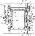
도 1은 본 발명에 따른 연결 장치의 바람직한 실시형태의 개략적인 단면도를 도시하며,
도 2는 연결 요소의 개략적인 단면도이고,
도 3은 본 발명에 따른 연결 장치의 제 2 실시형태의 개략적인 단면도를 도시한다.Best Mode for Carrying Out the Invention Hereinafter, the present invention will be described in detail based on preferred embodiments with reference to the accompanying drawings.
In the figure:
Figure 1 shows a schematic cross-sectional view of a preferred embodiment of a connecting device according to the invention,
Figure 2 is a schematic cross-sectional view of a connecting element,
Figure 3 shows a schematic cross-sectional view of a second embodiment of the connecting device according to the invention.
연결 장치는 특히 진공 펌프에 연결된 제 1 튜브 단부(10)를, 특히 피진공배기 챔버에 연결된 제 2 튜브 단부(12)에 연결시키는 역할을 한다. 유체 연결을 위해 튜브 요소(14)가 제공된다. 후자는, 대향하는 양 단부에서 특히 도시되지 않은 조임 스크류를 통해 각각의 연결 링(16)에 연결된다. 연결 링(16)은 시일를 갖는 중심설정 링(18)을 포함한다. 중심설정 링(18)은 2 개의 튜브 단부(10, 12)의 플랜지(20)와 그 반대쪽의 플랜지(22) 사이에 각각 배치된다. 플랜지(22)는 2 개의 보유 요소(24)의 각각의 부분이다. 보유 요소(24)는 각각 환형 구조이고 튜브 요소(14)를 둘러싸고 있다. 2 개의 보유 요소(24)는 클램프(27)를 통해 제 1 튜브 단부(10) 및/또는 제 2 튜브 단부(12)에 각각 고정적으로 따라서 견고하게 연결된다.The connecting device serves in particular to connect the
튜브 요소(14)는 연결 요소(26)를 통해 2 개의 튜브 단부(10, 12)에 연결되며, 2 개의 보유 요소(24) 역시 연결 요소(26)의 구성요소 부분이다. 특히 진공 펌프의 고장의 경우에 연결을 통해 토크가 전달될 수 있도록 연결이 실현된다. 상기 토크는 종축(28) 둘레로 발생하는 토크이다. 축방향으로, 즉 종축(28)의 방향으로, 2 개의 튜브 단부(10,12)에 대한 및/또는 2 개의 튜브 단부(10,12)에 고정적으로 연결된 보유 요소에 대한 튜브 요소의 적어도 약간의 변위가 가능하다. 이 목적을 위해, 보유 요소(24)(도 2)는 반경방향 내측을 향하는 돌출부(30)를 포함한다. 돌출부(30)는 돌출부(34)(도 1)가 내부로 연장되는 리세스(32)를 포함한다. 도시된 예시적인 실시형태에 있어서, 돌출부(34)는 스크류 헤드이다. 여기서, 리세스(32)의 직경은 스크류 헤드(34)의 직경보다 약간 크다.The
또한, 연결 장치는 디커플링 요소(36)를 포함한다. 이것은 2 개의 연결 요소(26)를 2 개의 튜브 단부(10, 12)로부터 기계적으로 디커플링시키는 역할을 하여, 축방향 힘, 즉 종축(28)을 따라 통과할 수 있는 힘이 전달될 수 없게 및/또는 그 전달이 상당히 감소될 수 있게 한다. 따라서, 진공 펌프로부터 피진공배기 챔버 및 그것에 연결된 구성요소로의 진동의 전달이 없거나 및/또는 약간의 진동 전달만이 있다. 도시된 예시적인 실시형태에 있어서, 디커플링 요소(36)는 환형으로 구성된 외부 요소(38)를 포함한다. 외부 요소(38)는 2 개의 환형으로 구성된 보유 요소(24)에 대해 축방향으로 변위되도록 구성된다. 외부 요소(38)와 2 개의 보유 요소(24) 사이에는 각각의 환형 밀봉 요소(40)가 배치된다.The connecting device also includes a
두 개의 보유 요소(24)의 내면에는 튜브 요소(14) 쪽으로 밀봉하기 위한 환형 밀봉 요소(42)가 제공될 수도 있다. 특히, 이 영역에서도 보유 요소(24)와 튜브 요소(14) 사이의 축방향 이동이 허용된다.The inner surface of the two retaining
디커플링 요소(36)의 외부 요소(38)는 웨브 요소(44)를 통해 튜브 요소(14)에 연결된다. 이것은 고정된 연결이며, 웨브 요소(44)는 예를 들면 스크류 연결을 통해 튜브 요소(14)의 웨브 형상 돌출부(46)에 연결된다. 튜브 요소(14)의 축방향 이동은 항상 외부 요소(38)의 축방향 이동을 야기한다.The
축방향 이동을 실현하기 위해, 도 1에 도시된 예시적인 실시형태에서 웨브(44, 46)에 제공된 연결 덕트(52)를 통해 서로 유체 연결되는 2 개의 유체 챔버(48, 50)가 형성된다. 따라서, 외부 요소(38)의 내부면, 2 개의 보유 요소(24)의 전면 및 튜브 요소(14)의 외부면에 의해 유체 챔버(48, 50)의 경계가 정해진다. 유체 챔버(48, 50)는 공급 덕트(54)를 포함하며, 공급 덕트(54) 내에는 밸브(56)가 배치된다. 따라서 밸브(56)를 통해, 유체, 특히 압축 공기가 2 개의 유체 챔버(48, 50)로 공급되거나 배출될 수 있다.In order to realize the axial movement, two
2 개의 튜브 단부(10, 12)를 축방향으로 디커플링시킴과 아울러 그에 따라 진동의 전달을 회피, 특히 감소시키기 위해, 본 발명에 따른 연결 장치의 도움으로 유체 챔버(48, 50) 내에 압력을 축적하는 것이 가능하다. 이것은 2 개의 대향하는 환형 보유 요소(24)가 멀어지는 방향으로 밀리게 한다. 진공 펌프를 작동하기 전에, 돌출부 및/또는 스크류 헤드(34)는 각각 리세스(32)의 바닥 위에 축방향으로 안착되기 때문에 2 개의 튜브 단부(10, 12) 사이에 축방향 연결이 이루어진다. 작동 중에는, 진공 펌프에 의해서 튜브 요소(14) 내 및 부가적으로 2 개의 튜브 단부(10, 12) 내에 진공이 발생한다. 이에 의해 반력이 생성된다. 대응하는 힘 비율의 경우, 이것은 돌출부(34)가 리세스(32)의 바닥 영역 상에 더 이상 안착하지 않게 한다.In order to axially decouple the two tube ends 10,12 and to thereby avoid, and in particular to reduce, the transmission of vibration, the pressure in the
따라서 신뢰성 있는 디커플링을 보장하기 위해, 유체 챔버(48, 50) 내의 압력은 진공에 적합해야 한다. 본 발명에 따르면, 이것은 공급 덕트(54)를 통해 압축 공기를 공급 또는 배출함으로써 간단한 방식으로 가능하다.Thus, to ensure reliable decoupling, the pressure in the
또한, 보유 요소(24)에 대한 외측 링(38)의 위치 및 그에 따른 튜브 요소(14)의 위치가 간단한 방식으로 판독될 수 있도록, 외측 링(38) 및/또는 2 개의 보유 요소(24) 중 하나에 마킹이 제공되는 것이 바람직하다. 따라서, 축방향 디커플링을 보장하기 위해 유체 챔버(48, 50) 내의 필요한 압력이 간단한 방식으로 결정될 수 있다.The
도 3에 도시된 실시형태에 있어서, 유사 및 동일 구성요소는 동일한 참조 번호로 표시된다.In the embodiment shown in Fig. 3, similar and like components are denoted by the same reference numerals.
본질적인 차이는 외측 링(38)이 튜브 요소(14)와 일체로 형성된다는 것이다. 도시된 예시적인 실시형태에 있어서는, 고형 웨브(58)을 통해 연결이 실현된다. 도시된 예시적인 실시형태에 있어서, 웨브(58)는 두 개의 유체 챔버(48, 50)를 연결하기 위한 어떤 보어도 포함하지 않는다. 오히려 각각의 유체 챔버(48, 50)에 대해 각각의 공급 덕트(60)가 제공되며, 이 공급 덕트(60) 내에는 각각의 밸브(62)가 배치된다. 따라서, 미세 조정이 가능하도록 두 개의 유체 챔버(48, 50) 내의 압력을 서로 독립적으로 조정할 수 있다. 따라서, 이 실시형태에서도 2 개의 마킹이 제공되는 것이 바람직한데, 하나의 마킹은 도 1에서 상측의 보유 요소(24)와 외부 요소(38) 사이의 상대적 위치를 나타내고, 두번째 마킹은 도 3에서 하측의 보유 요소(24)에 대한 상대적 위치를 나타낸다.An essential difference is that the
Claims (21)
상기 진공 펌프를 상기 피진공배기 챔버에 유체적으로 연결하기 위한 튜브 요소(14)로서,
상기 튜브 요소(14)는 상기 튜브 단부(10, 12)의 각각에 연결하기 위해 양 측면에 연결 요소(26)를 구비하며, 2 개의 상기 연결 요소 중 적어도 하나는 토크만을 전용으로 전달하도록 구성된,
상기 튜브 요소(14)와,
토크만을 전용으로 전달하도록 구성된 적어도 하나의 연결 요소(26)를 대응하는 상기 튜브 단부(10, 12)로부터 기계적으로 디커플링시키기 위한 디커플링 요소(36)를 포함하는
연결 장치.A connecting device for connecting a first tube end (10) configured to be connected to a vacuum pump to a second tube end (12) configured to be connected to a vacuum evacuation chamber,
A tube element (14) for fluidly connecting said vacuum pump to said evacuated evacuation chamber,
The tube element (14) has a connecting element (26) on both sides for connecting to each of the tube ends (10, 12), and at least one of the two connecting elements
The tube element 14,
Comprises a decoupling element (36) for mechanically decoupling at least one connecting element (26) configured to transmit only the torque exclusively from the corresponding tube end (10, 12)
Connection device.
상기 디커플링 요소(36)는 압축성 유체, 특히 가스로 채워진 적어도 하나의 유체 챔버(48, 50)를 포함하는 것을 특징으로 하는
연결 장치.The method according to claim 1,
Characterized in that said decoupling element (36) comprises at least one fluid chamber (48, 50) filled with a compressible fluid, in particular a gas
Connection device.
상기 디커플링 요소(36)에 의해 생성된 힘, 특히 발생된 축방향 힘은 조절 가능한 것을 특징으로 하는
연결 장치.3. The method according to claim 1 or 2,
Characterized in that the force produced by the decoupling element (36), in particular the generated axial force, is adjustable
Connection device.
상기 축방향 힘의 조절은 상기 유체 챔버(48, 50) 내의 압력을 변화시킴으로써 수행되는 것을 특징으로 하는
연결 장치.The method according to claim 2 or 3,
The adjustment of the axial force is performed by varying the pressure in the fluid chamber (48, 50)
Connection device.
2 개의 상기 연결 요소(26)는 토크만을 전용으로 전달하도록 구성된 것을 특징으로 하는
연결 장치.5. The method according to any one of claims 1 to 4,
Characterized in that the two coupling elements (26) are arranged to transmit only torque
Connection device.
상기 디커플링 요소(36)는 각각의 튜브 단부(10, 12)에 고정적으로 연결되도록 구성된 2 개의 보유 요소(24)를 포함하는 것을 특징으로 하는
연결 장치.6. The method according to any one of claims 1 to 5,
Characterized in that the decoupling element (36) comprises two holding elements (24) which are configured to be fixedly connected to the respective tube ends (10, 12)
Connection device.
상기 유체 챔버(48, 50)는 상기 두 개의 보유 요소(24) 사이에 배치되는 것을 특징으로 하는
연결 장치.The method according to claim 6,
Characterized in that the fluid chamber (48, 50) is arranged between the two holding elements (24)
Connection device.
상기 디커플링 요소(36)는 특히 상기 튜브 요소(14)를 완전히 둘러싸는 외부 요소(38)를 포함하는 것을 특징으로 하는
연결 장치.8. The method according to any one of claims 1 to 7,
Characterized in that the decoupling element (36) comprises an outer element (38) which completely surrounds the tube element (14)
Connection device.
상기 외부 요소(38)는 환형 구조를 갖는 것을 특징으로 하는
연결 장치.9. The method of claim 8,
Characterized in that said outer element (38) has an annular structure
Connection device.
상기 외부 요소(38)는 적어도 하나, 특히 두 개의 보유 요소(24)에 대해 축방향으로 변위되도록 구성된 것을 특징으로 하는
연결 장치.10. The method according to claim 8 or 9,
Characterized in that said outer element (38) is configured to be displaced axially relative to at least one, in particular two, retaining elements (24)
Connection device.
상기 외부 요소(38)와, 그것에 대해 변위되도록 구성된 상기 보유 요소(24) 사이에 배치된 제 1 밀봉 요소(40)를 포함하는 것을 특징으로 하는
연결 장치.11. The method according to any one of claims 8 to 10,
Characterized by comprising a first sealing element (40) disposed between said outer element (38) and said holding element (24) configured to be displaced therefrom
Connection device.
상기 외부 요소(38)와, 특히 축방향으로 변위되도록 구성된 상기 제 2 보유 요소(24) 사이에 배치된 제 2 밀봉 요소(40)를 포함하는 것을 특징으로 하는
연결 장치.12. The method of claim 11,
And a second sealing element (40) disposed between the outer element (38) and the second holding element (24) configured to be displaced in particular in the axial direction
Connection device.
상기 튜브 요소(14)와 상기 두 개의 보유 요소(24) 사이에 각각의 밀봉 요소(42)가 배치되는 것을 특징으로 하는
연결 장치.13. The method according to any one of claims 6 to 12,
Characterized in that a respective sealing element (42) is arranged between the tube element (14) and the two holding elements (24)
Connection device.
상기 외부 요소(38), 상기 튜브 요소(14) 및 상기 두 개의 보유 요소(24)에 의해 상기 적어도 하나의 유체 챔버(48, 50)의 경계가 설정되는 것을 특징으로 하는
연결 장치.14. The method according to any one of claims 8 to 13,
Characterized in that the boundary of the at least one fluid chamber (48, 50) is established by the outer element (38), the tube element (14) and the two holding elements
Connection device.
상기 적어도 하나의 유체 챔버(48, 50)가 상기 튜브 요소(14)를 환형으로 둘러싸는 것을 특징으로 하는
연결 장치.15. The method according to any one of claims 1 to 14,
Characterized in that the at least one fluid chamber (48, 50) annularly surrounds the tube element (14)
Connection device.
상기 적어도 하나의 유체 챔버(48, 50)는 공급 덕트(54, 60)를 포함하고, 상기 공급 덕트 내에는 특히 밸브(56, 62)가 배치되는 것을 특징으로 하는
연결 장치.16. The method according to any one of claims 1 to 15,
Characterized in that said at least one fluid chamber (48, 50) comprises supply ducts (54, 60), in particular valves 56, 62 being arranged in said supply duct
Connection device.
상기 외부 요소(38)는 특히 웨브 요소(44, 58)를 거쳐서 튜브 요소(14)와 고정적으로 연결되는, 특히 일체적으로 형성되는 것을 특징으로 하는
연결 장치.17. The method according to any one of claims 8 to 16,
The outer element 38 is characterized in that it is particularly integrally formed and fixedly connected to the tube element 14, in particular via the web elements 44, 58
Connection device.
상기 디커플링 요소(36)는 압력이 바람직하게는 서로 별도로 조절되도록 구성된 2 개의 유체 챔버(48, 50)를 포함하는 것을 특징으로 하는
연결 장치.18. The method according to any one of claims 2 to 17,
Characterized in that the decoupling element (36) comprises two fluid chambers (48, 50) whose pressure is preferably adapted to be adjusted separately from each other
Connection device.
토크 전달 전용으로 구성된 적어도 하나의 연결 요소(26)는 리세스(32) 내로 연장되는 특히 축방향으로 배열된 돌출부(34)를 포함하는 것을 특징으로 하는
연결 장치.19. The method according to any one of claims 1 to 18,
Characterized in that the at least one connecting element (26) configured for torque transmission comprises a particularly axially arranged protrusion (34) extending into the recess (32)
Connection device.
정상 작동 중에 토크가 전혀 전달되지 않도록 상기 리세스(32)의 단면이 상기 돌출부(34)의 단면보다 큰 것을 특징으로 하는
연결 장치.20. The method of claim 19,
Characterized in that the cross section of the recess (32) is larger than the cross section of the projection (34) so that no torque is transmitted during normal operation
Connection device.
상기 외부 요소 및/또는 적어도 하나의 상기 보유 요소(24)는 작동 중 기계적 디커플링을 표시하기 위한 마킹을 포함하는 것을 특징으로 하는
연결 장치.21. The method according to any one of claims 8 to 20,
Characterized in that the external element and / or the at least one retaining element (24) comprises a marking for indicating mechanical decoupling during operation
Connection device.
Applications Claiming Priority (3)
| Application Number | Priority Date | Filing Date | Title |
|---|---|---|---|
| DE202015008803.1U DE202015008803U1 (en) | 2015-12-23 | 2015-12-23 | connecting device |
| DE202015008803.1 | 2015-12-23 | ||
| PCT/EP2016/080975 WO2017108528A1 (en) | 2015-12-23 | 2016-12-14 | Connection device |
Publications (1)
| Publication Number | Publication Date |
|---|---|
| KR20180098262A true KR20180098262A (en) | 2018-09-03 |
Family
ID=57777579
Family Applications (1)
| Application Number | Title | Priority Date | Filing Date |
|---|---|---|---|
| KR1020187017742A Abandoned KR20180098262A (en) | 2015-12-23 | 2016-12-14 | Connecting device |
Country Status (8)
| Country | Link |
|---|---|
| US (1) | US11143351B2 (en) |
| EP (1) | EP3394452B1 (en) |
| JP (1) | JP6937306B2 (en) |
| KR (1) | KR20180098262A (en) |
| CN (1) | CN108474382B (en) |
| DE (1) | DE202015008803U1 (en) |
| SG (1) | SG11201805307TA (en) |
| WO (1) | WO2017108528A1 (en) |
Families Citing this family (2)
| Publication number | Priority date | Publication date | Assignee | Title |
|---|---|---|---|---|
| GB2587367A (en) | 2019-09-24 | 2021-03-31 | Edwards Ltd | Vibration damping connector systems |
| GB2641282A (en) * | 2024-05-24 | 2025-11-26 | Edwards Ltd | Differentially pumped vibration isolator |
Citations (1)
| Publication number | Priority date | Publication date | Assignee | Title |
|---|---|---|---|---|
| EP2410184A1 (en) | 2010-04-16 | 2012-01-25 | Agilent Technologies, Inc. | Vibration damper for vacuum pumps |
Family Cites Families (25)
| Publication number | Priority date | Publication date | Assignee | Title |
|---|---|---|---|---|
| US1499050A (en) * | 1921-06-17 | 1924-06-24 | Ernest L Broome | Flexible expansion joint |
| US3298980A (en) | 1963-08-01 | 1967-01-17 | Union Carbide Corp | Alkylene oxide polymer compositions flexibilized with salts of carboxylic acids |
| US3298680A (en) * | 1964-06-02 | 1967-01-17 | Bethlehem Steel Corp | Vacuum degassing apparatus |
| US4523612A (en) * | 1983-04-15 | 1985-06-18 | The United States Of America As Represented By The United States Department Of Energy | Apparatus and method for suppressing vibration and displacement of a bellows |
| US5671956A (en) * | 1996-03-07 | 1997-09-30 | Kimball Physics, Inc. | Vacuum system coupler |
| DE10119075A1 (en) | 2001-04-19 | 2002-10-24 | Leybold Vakuum Gmbh | Vacuum line for connecting turbomolecular vacuum pump with e.g. analysis apparatus comprises flexible hose section fitted with actively controlled axial magnetic bearing which acts as vibration damper |
| JP4250353B2 (en) | 2001-06-22 | 2009-04-08 | エドワーズ株式会社 | Vacuum pump |
| GB0402625D0 (en) | 2004-02-06 | 2004-03-10 | Boc Group Plc | Vibration damper |
| FR2867823B1 (en) * | 2004-03-22 | 2006-07-14 | Cit Alcatel | SHOCK ABSORBER CONNECTION FOR VACUUM PUMP |
| JP2006077714A (en) | 2004-09-10 | 2006-03-23 | Boc Edwards Kk | Damper and vacuum pump |
| DE202005011679U1 (en) | 2004-09-16 | 2005-10-20 | Leybold Vacuum Gmbh | Vibration damper for gas-tight connection of vacuum pump with vacuum device, has damper device with elastic damping ring between sealing ring of vacuum device and sealing ring of vacuum pump, where sealing sleeve is sealed to both rings |
| DE102005020904A1 (en) | 2005-05-07 | 2006-11-09 | Leybold Vacuum Gmbh | Vacuum pump assembly |
| DE102006004314A1 (en) | 2006-01-31 | 2007-08-02 | Leybold Vacuum Gmbh | Vacuum pipe for vacuum pump has annular gas filled damping hose to dampen vibration between vacuum connection sections |
| GB0620723D0 (en) * | 2006-10-19 | 2006-11-29 | Boc Group Plc | Vibration isolator |
| DE102007008859A1 (en) | 2007-02-23 | 2008-08-28 | Oerlikon Leybold Vacuum Gmbh | vacuum line |
| JP2009097673A (en) | 2007-10-18 | 2009-05-07 | Kurashiki Kako Co Ltd | Vibration isolating joint |
| DE102008027006A1 (en) * | 2007-12-03 | 2009-06-04 | Sms Mevac Gmbh | Apparatus for the secondary and vacuum metallurgical treatment of liquid steel |
| DE102007061188A1 (en) * | 2007-12-17 | 2009-06-18 | Vat Holding Ag | Flange device for vacuum-tightly connecting vacuum component i.e. piping component, with counter flange, has ring piece connected with base piece by elastic sealing ring and exhibiting degree of freedom for movement opposite to base piece |
| DE102008028199A1 (en) | 2008-06-12 | 2009-12-17 | Pfeiffer Vacuum Gmbh | connecting element |
| JP5480545B2 (en) | 2009-07-03 | 2014-04-23 | 倉敷化工株式会社 | Anti-vibration joint |
| CN201507593U (en) * | 2009-08-25 | 2010-06-16 | 东莞宏威数码机械有限公司 | Shock-absorbing device |
| JP5632992B2 (en) | 2010-11-22 | 2014-12-03 | 日本電子株式会社 | Turbo molecular pump connection device |
| CN103635733B (en) * | 2011-07-06 | 2015-05-20 | 日本维克托利克株式会社 | Flexible expansion joint |
| DE102013100483A1 (en) * | 2013-01-17 | 2014-07-17 | Andreas von Keitz | breakaway coupling |
| GB2521340B (en) * | 2013-10-14 | 2017-10-04 | Edwards Ltd | Vacuum system pipe couplings |
-
2015
- 2015-12-23 DE DE202015008803.1U patent/DE202015008803U1/en not_active Expired - Lifetime
-
2016
- 2016-12-14 WO PCT/EP2016/080975 patent/WO2017108528A1/en not_active Ceased
- 2016-12-14 CN CN201680075873.6A patent/CN108474382B/en active Active
- 2016-12-14 JP JP2018532390A patent/JP6937306B2/en active Active
- 2016-12-14 SG SG11201805307TA patent/SG11201805307TA/en unknown
- 2016-12-14 KR KR1020187017742A patent/KR20180098262A/en not_active Abandoned
- 2016-12-14 EP EP16825345.8A patent/EP3394452B1/en active Active
- 2016-12-14 US US16/060,288 patent/US11143351B2/en not_active Expired - Fee Related
Patent Citations (1)
| Publication number | Priority date | Publication date | Assignee | Title |
|---|---|---|---|---|
| EP2410184A1 (en) | 2010-04-16 | 2012-01-25 | Agilent Technologies, Inc. | Vibration damper for vacuum pumps |
Also Published As
| Publication number | Publication date |
|---|---|
| US11143351B2 (en) | 2021-10-12 |
| CN108474382B (en) | 2021-01-22 |
| SG11201805307TA (en) | 2018-07-30 |
| DE202015008803U1 (en) | 2017-03-24 |
| CN108474382A (en) | 2018-08-31 |
| JP2019501351A (en) | 2019-01-17 |
| JP6937306B2 (en) | 2021-09-22 |
| EP3394452A1 (en) | 2018-10-31 |
| EP3394452B1 (en) | 2023-09-27 |
| US20180363825A1 (en) | 2018-12-20 |
| WO2017108528A1 (en) | 2017-06-29 |
Similar Documents
| Publication | Publication Date | Title |
|---|---|---|
| US6582206B2 (en) | Diaphragm chucking with elasticity adjustment | |
| US8727311B2 (en) | Vacuum valve with gas-tight shaft penetration | |
| US9353861B2 (en) | Coupling structure for piston used in fluid-pressure cylinder, and coupling method therefor | |
| EP3401133B1 (en) | Leveling valve | |
| JPH0777162A (en) | Diaphragm pump with at least two diaphragms | |
| JP6166362B2 (en) | Valves and valve diaphragms | |
| JP6546746B2 (en) | Fluid pressure cylinder | |
| KR20190140086A (en) | plug valve and stem sealing assembly | |
| JP6858856B2 (en) | Turbocharger | |
| DK2634460T3 (en) | Ship with a skottætning in the field of shaft bushings | |
| KR20180005687A (en) | Adjustable Spring Support | |
| CN108474382B (en) | Connecting device | |
| CN114981556A (en) | Slave device for a clutch system and clutch system for a vehicle | |
| US20100260594A1 (en) | Vacuum line | |
| JP6501391B2 (en) | Rotating machine system | |
| US20190226505A1 (en) | Hydrostatic actuator with a split dynamic seal portion | |
| KR100994067B1 (en) | Mechanical seal for high pressure and high speed | |
| CN110513485A (en) | A kind of bellows sealing structure of revolving drum of multipurpose continuous drying equipment | |
| CN110785591B (en) | Diaphragm Sealed Double Seat Valve and Actuator | |
| KR101028112B1 (en) | Bellows type mechanical sealing assembly | |
| US20080028925A1 (en) | Piston-cylinder unit | |
| CN119522150A (en) | Clamping and/or braking devices for wet environments | |
| EP4173911B1 (en) | Diaphragm brake cylinder with reduction ring integrated in the diaphragm | |
| EP0998643B1 (en) | Boltless pipe connector | |
| CN105121921B (en) | Slip ring seals |
Legal Events
| Date | Code | Title | Description |
|---|---|---|---|
| PA0105 | International application |
St.27 status event code: A-0-1-A10-A15-nap-PA0105 |
|
| PG1501 | Laying open of application |
St.27 status event code: A-1-1-Q10-Q12-nap-PG1501 |
|
| A201 | Request for examination | ||
| P11-X000 | Amendment of application requested |
St.27 status event code: A-2-2-P10-P11-nap-X000 |
|
| P13-X000 | Application amended |
St.27 status event code: A-2-2-P10-P13-nap-X000 |
|
| PA0201 | Request for examination |
St.27 status event code: A-1-2-D10-D11-exm-PA0201 |
|
| E902 | Notification of reason for refusal | ||
| PE0902 | Notice of grounds for rejection |
St.27 status event code: A-1-2-D10-D21-exm-PE0902 |
|
| E13-X000 | Pre-grant limitation requested |
St.27 status event code: A-2-3-E10-E13-lim-X000 |
|
| P11-X000 | Amendment of application requested |
St.27 status event code: A-2-2-P10-P11-nap-X000 |
|
| P13-X000 | Application amended |
St.27 status event code: A-2-2-P10-P13-nap-X000 |
|
| E701 | Decision to grant or registration of patent right | ||
| PE0701 | Decision of registration |
St.27 status event code: A-1-2-D10-D22-exm-PE0701 |
|
| PC1904 | Unpaid initial registration fee |
St.27 status event code: A-2-2-U10-U14-oth-PC1904 St.27 status event code: N-2-6-B10-B12-nap-PC1904 |