KR20180098174A - Virtual reality-based radiology practice apparatus and method - Google Patents
Virtual reality-based radiology practice apparatus and method Download PDFInfo
- Publication number
- KR20180098174A KR20180098174A KR1020180022591A KR20180022591A KR20180098174A KR 20180098174 A KR20180098174 A KR 20180098174A KR 1020180022591 A KR1020180022591 A KR 1020180022591A KR 20180022591 A KR20180022591 A KR 20180022591A KR 20180098174 A KR20180098174 A KR 20180098174A
- Authority
- KR
- South Korea
- Prior art keywords
- virtual
- hmd
- hand
- image
- main server
- Prior art date
- Legal status (The legal status is an assumption and is not a legal conclusion. Google has not performed a legal analysis and makes no representation as to the accuracy of the status listed.)
- Granted
Links
Images


Classifications
-
- G—PHYSICS
- G06—COMPUTING OR CALCULATING; COUNTING
- G06F—ELECTRIC DIGITAL DATA PROCESSING
- G06F1/00—Details not covered by groups G06F3/00 - G06F13/00 and G06F21/00
- G06F1/16—Constructional details or arrangements
- G06F1/1613—Constructional details or arrangements for portable computers
- G06F1/163—Wearable computers, e.g. on a belt
-
- G—PHYSICS
- G09—EDUCATION; CRYPTOGRAPHY; DISPLAY; ADVERTISING; SEALS
- G09B—EDUCATIONAL OR DEMONSTRATION APPLIANCES; APPLIANCES FOR TEACHING, OR COMMUNICATING WITH, THE BLIND, DEAF OR MUTE; MODELS; PLANETARIA; GLOBES; MAPS; DIAGRAMS
- G09B23/00—Models for scientific, medical, or mathematical purposes, e.g. full-sized devices for demonstration purposes
- G09B23/28—Models for scientific, medical, or mathematical purposes, e.g. full-sized devices for demonstration purposes for medicine
- G09B23/286—Models for scientific, medical, or mathematical purposes, e.g. full-sized devices for demonstration purposes for medicine for scanning or photography techniques, e.g. X-rays, ultrasonics
-
- G—PHYSICS
- G02—OPTICS
- G02B—OPTICAL ELEMENTS, SYSTEMS OR APPARATUS
- G02B27/00—Optical systems or apparatus not provided for by any of the groups G02B1/00 - G02B26/00, G02B30/00
- G02B27/0093—Optical systems or apparatus not provided for by any of the groups G02B1/00 - G02B26/00, G02B30/00 with means for monitoring data relating to the user, e.g. head-tracking, eye-tracking
-
- G—PHYSICS
- G02—OPTICS
- G02B—OPTICAL ELEMENTS, SYSTEMS OR APPARATUS
- G02B27/00—Optical systems or apparatus not provided for by any of the groups G02B1/00 - G02B26/00, G02B30/00
- G02B27/01—Head-up displays
- G02B27/017—Head mounted
-
- G—PHYSICS
- G02—OPTICS
- G02B—OPTICAL ELEMENTS, SYSTEMS OR APPARATUS
- G02B27/00—Optical systems or apparatus not provided for by any of the groups G02B1/00 - G02B26/00, G02B30/00
- G02B27/01—Head-up displays
- G02B27/017—Head mounted
- G02B27/0172—Head mounted characterised by optical features
-
- G—PHYSICS
- G06—COMPUTING OR CALCULATING; COUNTING
- G06F—ELECTRIC DIGITAL DATA PROCESSING
- G06F1/00—Details not covered by groups G06F3/00 - G06F13/00 and G06F21/00
- G06F1/16—Constructional details or arrangements
- G06F1/1613—Constructional details or arrangements for portable computers
- G06F1/1633—Constructional details or arrangements of portable computers not specific to the type of enclosures covered by groups G06F1/1615 - G06F1/1626
- G06F1/1684—Constructional details or arrangements related to integrated I/O peripherals not covered by groups G06F1/1635 - G06F1/1675
- G06F1/1686—Constructional details or arrangements related to integrated I/O peripherals not covered by groups G06F1/1635 - G06F1/1675 the I/O peripheral being an integrated camera
-
- G—PHYSICS
- G06—COMPUTING OR CALCULATING; COUNTING
- G06F—ELECTRIC DIGITAL DATA PROCESSING
- G06F1/00—Details not covered by groups G06F3/00 - G06F13/00 and G06F21/00
- G06F1/16—Constructional details or arrangements
- G06F1/1613—Constructional details or arrangements for portable computers
- G06F1/1633—Constructional details or arrangements of portable computers not specific to the type of enclosures covered by groups G06F1/1615 - G06F1/1626
- G06F1/1684—Constructional details or arrangements related to integrated I/O peripherals not covered by groups G06F1/1635 - G06F1/1675
- G06F1/1694—Constructional details or arrangements related to integrated I/O peripherals not covered by groups G06F1/1635 - G06F1/1675 the I/O peripheral being a single or a set of motion sensors for pointer control or gesture input obtained by sensing movements of the portable computer
-
- G—PHYSICS
- G06—COMPUTING OR CALCULATING; COUNTING
- G06F—ELECTRIC DIGITAL DATA PROCESSING
- G06F3/00—Input arrangements for transferring data to be processed into a form capable of being handled by the computer; Output arrangements for transferring data from processing unit to output unit, e.g. interface arrangements
- G06F3/01—Input arrangements or combined input and output arrangements for interaction between user and computer
- G06F3/011—Arrangements for interaction with the human body, e.g. for user immersion in virtual reality
- G06F3/012—Head tracking input arrangements
-
- G—PHYSICS
- G06—COMPUTING OR CALCULATING; COUNTING
- G06F—ELECTRIC DIGITAL DATA PROCESSING
- G06F3/00—Input arrangements for transferring data to be processed into a form capable of being handled by the computer; Output arrangements for transferring data from processing unit to output unit, e.g. interface arrangements
- G06F3/01—Input arrangements or combined input and output arrangements for interaction between user and computer
- G06F3/011—Arrangements for interaction with the human body, e.g. for user immersion in virtual reality
- G06F3/013—Eye tracking input arrangements
-
- G—PHYSICS
- G06—COMPUTING OR CALCULATING; COUNTING
- G06F—ELECTRIC DIGITAL DATA PROCESSING
- G06F3/00—Input arrangements for transferring data to be processed into a form capable of being handled by the computer; Output arrangements for transferring data from processing unit to output unit, e.g. interface arrangements
- G06F3/01—Input arrangements or combined input and output arrangements for interaction between user and computer
- G06F3/016—Input arrangements with force or tactile feedback as computer generated output to the user
-
- G—PHYSICS
- G06—COMPUTING OR CALCULATING; COUNTING
- G06F—ELECTRIC DIGITAL DATA PROCESSING
- G06F3/00—Input arrangements for transferring data to be processed into a form capable of being handled by the computer; Output arrangements for transferring data from processing unit to output unit, e.g. interface arrangements
- G06F3/01—Input arrangements or combined input and output arrangements for interaction between user and computer
- G06F3/017—Gesture based interaction, e.g. based on a set of recognized hand gestures
-
- G—PHYSICS
- G06—COMPUTING OR CALCULATING; COUNTING
- G06F—ELECTRIC DIGITAL DATA PROCESSING
- G06F3/00—Input arrangements for transferring data to be processed into a form capable of being handled by the computer; Output arrangements for transferring data from processing unit to output unit, e.g. interface arrangements
- G06F3/01—Input arrangements or combined input and output arrangements for interaction between user and computer
- G06F3/03—Arrangements for converting the position or the displacement of a member into a coded form
- G06F3/0304—Detection arrangements using opto-electronic means
- G06F3/0325—Detection arrangements using opto-electronic means using a plurality of light emitters or reflectors or a plurality of detectors forming a reference frame from which to derive the orientation of the object, e.g. by triangulation or on the basis of reference deformation in the picked up image
-
- G—PHYSICS
- G06—COMPUTING OR CALCULATING; COUNTING
- G06F—ELECTRIC DIGITAL DATA PROCESSING
- G06F3/00—Input arrangements for transferring data to be processed into a form capable of being handled by the computer; Output arrangements for transferring data from processing unit to output unit, e.g. interface arrangements
- G06F3/01—Input arrangements or combined input and output arrangements for interaction between user and computer
- G06F3/03—Arrangements for converting the position or the displacement of a member into a coded form
- G06F3/033—Pointing devices displaced or positioned by the user, e.g. mice, trackballs, pens or joysticks; Accessories therefor
- G06F3/0346—Pointing devices displaced or positioned by the user, e.g. mice, trackballs, pens or joysticks; Accessories therefor with detection of the device orientation or free movement in a three-dimensional [3D] space, e.g. 3D mice, 6-DOF [six degrees of freedom] pointers using gyroscopes, accelerometers or tilt-sensors
-
- G—PHYSICS
- G06—COMPUTING OR CALCULATING; COUNTING
- G06F—ELECTRIC DIGITAL DATA PROCESSING
- G06F3/00—Input arrangements for transferring data to be processed into a form capable of being handled by the computer; Output arrangements for transferring data from processing unit to output unit, e.g. interface arrangements
- G06F3/01—Input arrangements or combined input and output arrangements for interaction between user and computer
- G06F3/048—Interaction techniques based on graphical user interfaces [GUI]
- G06F3/0481—Interaction techniques based on graphical user interfaces [GUI] based on specific properties of the displayed interaction object or a metaphor-based environment, e.g. interaction with desktop elements like windows or icons, or assisted by a cursor's changing behaviour or appearance
- G06F3/04815—Interaction with a metaphor-based environment or interaction object displayed as three-dimensional [3D], e.g. changing the user viewpoint with respect to the environment or object
-
- G—PHYSICS
- G06—COMPUTING OR CALCULATING; COUNTING
- G06F—ELECTRIC DIGITAL DATA PROCESSING
- G06F3/00—Input arrangements for transferring data to be processed into a form capable of being handled by the computer; Output arrangements for transferring data from processing unit to output unit, e.g. interface arrangements
- G06F3/01—Input arrangements or combined input and output arrangements for interaction between user and computer
- G06F3/048—Interaction techniques based on graphical user interfaces [GUI]
- G06F3/0484—Interaction techniques based on graphical user interfaces [GUI] for the control of specific functions or operations, e.g. selecting or manipulating an object, an image or a displayed text element, setting a parameter value or selecting a range
- G06F3/04842—Selection of displayed objects or displayed text elements
-
- G—PHYSICS
- G06—COMPUTING OR CALCULATING; COUNTING
- G06T—IMAGE DATA PROCESSING OR GENERATION, IN GENERAL
- G06T15/00—Three-dimensional [3D] image rendering
- G06T15/08—Volume rendering
-
- G—PHYSICS
- G06—COMPUTING OR CALCULATING; COUNTING
- G06T—IMAGE DATA PROCESSING OR GENERATION, IN GENERAL
- G06T17/00—Three-dimensional [3D] modelling for computer graphics
- G06T17/20—Finite element generation, e.g. wire-frame surface description, tesselation
-
- G—PHYSICS
- G06—COMPUTING OR CALCULATING; COUNTING
- G06T—IMAGE DATA PROCESSING OR GENERATION, IN GENERAL
- G06T19/00—Manipulating three-dimensional [3D] models or images for computer graphics
- G06T19/003—Navigation within 3D models or images
-
- G—PHYSICS
- G06—COMPUTING OR CALCULATING; COUNTING
- G06T—IMAGE DATA PROCESSING OR GENERATION, IN GENERAL
- G06T19/00—Manipulating three-dimensional [3D] models or images for computer graphics
- G06T19/20—Editing of three-dimensional [3D] images, e.g. changing shapes or colours, aligning objects or positioning parts
-
- G—PHYSICS
- G09—EDUCATION; CRYPTOGRAPHY; DISPLAY; ADVERTISING; SEALS
- G09B—EDUCATIONAL OR DEMONSTRATION APPLIANCES; APPLIANCES FOR TEACHING, OR COMMUNICATING WITH, THE BLIND, DEAF OR MUTE; MODELS; PLANETARIA; GLOBES; MAPS; DIAGRAMS
- G09B23/00—Models for scientific, medical, or mathematical purposes, e.g. full-sized devices for demonstration purposes
- G09B23/28—Models for scientific, medical, or mathematical purposes, e.g. full-sized devices for demonstration purposes for medicine
- G09B23/283—Models for scientific, medical, or mathematical purposes, e.g. full-sized devices for demonstration purposes for medicine for dentistry or oral hygiene
-
- H04N5/225—
-
- G—PHYSICS
- G02—OPTICS
- G02B—OPTICAL ELEMENTS, SYSTEMS OR APPARATUS
- G02B27/00—Optical systems or apparatus not provided for by any of the groups G02B1/00 - G02B26/00, G02B30/00
- G02B27/01—Head-up displays
- G02B27/0101—Head-up displays characterised by optical features
- G02B2027/0138—Head-up displays characterised by optical features comprising image capture systems, e.g. camera
-
- G—PHYSICS
- G06—COMPUTING OR CALCULATING; COUNTING
- G06T—IMAGE DATA PROCESSING OR GENERATION, IN GENERAL
- G06T2207/00—Indexing scheme for image analysis or image enhancement
- G06T2207/10—Image acquisition modality
- G06T2207/10072—Tomographic images
-
- G—PHYSICS
- G06—COMPUTING OR CALCULATING; COUNTING
- G06T—IMAGE DATA PROCESSING OR GENERATION, IN GENERAL
- G06T2207/00—Indexing scheme for image analysis or image enhancement
- G06T2207/20—Special algorithmic details
- G06T2207/20084—Artificial neural networks [ANN]
Landscapes
- Engineering & Computer Science (AREA)
- Physics & Mathematics (AREA)
- Theoretical Computer Science (AREA)
- General Physics & Mathematics (AREA)
- General Engineering & Computer Science (AREA)
- Human Computer Interaction (AREA)
- Computer Hardware Design (AREA)
- Optics & Photonics (AREA)
- Health & Medical Sciences (AREA)
- Software Systems (AREA)
- Computer Graphics (AREA)
- Medical Informatics (AREA)
- General Health & Medical Sciences (AREA)
- Pure & Applied Mathematics (AREA)
- Business, Economics & Management (AREA)
- Educational Administration (AREA)
- Educational Technology (AREA)
- Chemical & Material Sciences (AREA)
- Mathematical Physics (AREA)
- Mathematical Optimization (AREA)
- Mathematical Analysis (AREA)
- Medicinal Chemistry (AREA)
- Computational Mathematics (AREA)
- Algebra (AREA)
- Radar, Positioning & Navigation (AREA)
- Nuclear Medicine, Radiotherapy & Molecular Imaging (AREA)
- Radiology & Medical Imaging (AREA)
- Remote Sensing (AREA)
- Geometry (AREA)
- Architecture (AREA)
- Epidemiology (AREA)
- Public Health (AREA)
- Oral & Maxillofacial Surgery (AREA)
- Apparatus For Radiation Diagnosis (AREA)
- Processing Or Creating Images (AREA)
- Measuring And Recording Apparatus For Diagnosis (AREA)
- Quality & Reliability (AREA)
- Computer Vision & Pattern Recognition (AREA)
Abstract
본 발명은 실습자가 머리 장착형 디스플레이(HMD)를 장착하고, 손에 손 장착부를 착용하고, 시청각적 가상현실상에서 제공된 가상 방사선실습 환경에서, 가상 방사선 장비를 조작하여 가상 방사선 실습을 행하되, 손 장착부로부터 실습자의 손의 위치와 각도를 핸드 모션 콘트롤러가 수신하여, 가상 방사선 장비를 동작시키게 하고, 가상 방사선 장비가 동작 됨에 따른 소정 결과를 가상으로 출력하게 하는, 가상현실 기반 방사선학 실습 장치 및 방법에 관한 것이다.
본 발명의 가상 방사선학 실습 장치는, 실습자의 머리에 장착되며, HMD 영상출력부로, 가상 방사선학 실습을 위해, 가상 방사선 장치를 포함하는 영상이 출력되는, HMD 머리장착부; 실습자의 손에 장착되며, 영상 상에 가상 방사선 장치를 조작하기 위해, 실습자의 손이 움직일때, 실습자의 손 움직임신호를 검출하는 손 움직임 검출부를 포함하는, HMD 손장착부; HMD 손장착부로부터 손 움직임신호를 수신하여 메인서버로 전송하고, 메인서버로 부터 수신된 영상을 HMD 머리장착부로 전송하는, HMD 제어부; HMD 제어부로부터 수신한 손 움직임신호를 수신하고, 손 움직임 신호에 따라서, 영상상에서, 실습자의 가상의 손인, 손 움직임 표시자가 움직이며, 움직여진 손 움직임 표시자를 포함하는 영상을, HMD 제어부로 전송하는 메인서버;를 포함하여 이루어진 것을 특징으로 한다.The present invention relates to a virtual radiological training system for a practitioner who wears a head-mounted display (HMD), wears a hand mount on a hand, operates a virtual radiological equipment in a virtual radiological training environment provided on an audiovisual virtual reality, To a virtual reality-based radiological exercise apparatus and method for causing a hand motion controller to receive a position and an angle of a hand of a practitioner to cause a virtual radiological apparatus to operate and to output a virtual result as a result of the operation of the virtual radiological apparatus .
The virtual radiological training apparatus of the present invention includes an HMD head mounting unit mounted on a head of an practitioner and outputting an image including a virtual radiological apparatus to an HMD image output unit for a virtual radiography exercise; An HMD hand mount mounted on the hands of the practitioner and including a hand motion detection section for detecting a hand motion signal of the practitioner when the hands of the practitioner are moved to manipulate the virtual radiation apparatus on the image; An HMD controller for receiving a hand motion signal from the HMD hand mount and transmitting the hand motion signal to the main server and transmitting the image received from the main server to the HMD head mount; A virtual hand of a practitioner, a hand motion indicator moves on the image, and an image including the moved hand motion indicator is transmitted to the HMD controller in response to the hand motion signal received from the HMD controller And a main server.

Description
본 발명은 실습자가 머리 장착형 디스플레이(HMD)를 장착하고, 손에 손 장착부를 착용하고, 시청각적 가상현실상에서 제공된 가상 방사선실습 환경에서, 가상 방사선 장비를 조작하여 가상 방사선 실습을 행하되, 손 장착부로부터 실습자의 손의 위치와 각도를 핸드 모션 콘트롤러가 수신하여, 가상 방사선 장비를 동작시키게 하고, 가상 방사선 장비가 동작 됨에 따른 소정 결과를 가상으로 출력하게 하는, 가상현실 기반 방사선학 실습 장치 및 방법에 관한 것이다.The present invention relates to a virtual radiological training system for a practitioner who wears a head-mounted display (HMD), wears a hand mount on a hand, operates a virtual radiological equipment in a virtual radiological training environment provided on an audiovisual virtual reality, To a virtual reality-based radiological exercise apparatus and method for causing a hand motion controller to receive a position and an angle of a hand of a practitioner to cause a virtual radiological apparatus to operate and to output a virtual result as a result of the operation of the virtual radiological apparatus .
일반적으로, 방사선 장비는 방사선에 노출될 우려가 있어 상당히 위험하기 때문에, 이를 다루는 사람은, 고도의 숙련된 전문가 일 것이 요구되는 장비이다.In general, radiation equipment is highly dangerous because it can be exposed to radiation, so it is equipment that requires highly skilled professionals to handle it.
의료용 방사선 장비로서, 감마 카메라, 컴퓨터 단층촬영장치, 갑상선 섭취율 측정장치, X선 장치, 선형 가속기, 사이클로트론 등등 다양한 장치가 있으며, 같은 방사선 장비들이라도 제조사별로 기기들의 사용법 등이 다른 경우가 많다.There are various devices such as a gamma camera, a computed tomography apparatus, a thyroid dose measuring apparatus, an X-ray apparatus, a linear accelerator, a cyclotron, and the like.
미래의 의료전문가는 사람의 생명과 직결된 의료용 방사선 장비를 가능한 한 다 숙지할 필요가 있다. Future medical professionals need to know as much as possible the medical radiation equipment that is directly connected to the life of a person.
그러나, 이러한 의료용 방사선 장비들은 상당히 고가이고, 이들 장비가 크기 때문에 공간도 많이 차지하며, 또한, 이들을 관리하기 위한 전문관리인이 필요하다. 따라서, 일반적으로, 방사선학 실습을 필요로 하는 학교 또는 학과들이 이러한 장비를 전부 구비하는 것은 쉽지 않다.However, these medical radiation devices are quite expensive, and because of their large size, they take up a lot of space and also require a professional manager to manage them. Thus, in general, it is not easy for schools or departments that need radiological practice to have all of these equipment.
종래에, 방사선학 실습을 필요로 하는 학교 또는 학과들에서, 방사선학 실습에 있어서, 실제 방사선 장비와 마네킹을 이용하여 실습을 행한다. 따라서, 실습자 또는 교육자는 방사선에 노출될 우려가 있다.Conventionally, in schools or departments requiring radiological practice, the radiological practice is practiced using actual radiation equipment and manikin. Therefore, the practitioner or the educator may be exposed to radiation.
그러므로 저비용에 다양한 의료용 방사선 장비를 이용한 다양한 실습이 가능하고, 방사선에 노출될 위험이 없는 방사선학 실습 장치가 요망된다.Therefore, there is a need for a radiological training apparatus which can perform various exercises using various medical radiological apparatuses at low cost, and there is no risk of exposure to radiation.
이를 위해, 본 발명에서는 가상현실 기반 방사선학 실습 장치를 제안한다.To this end, the present invention proposes a virtual reality-based radiological training apparatus.
가상현실상에서 방사선학 실습을 할 경우, 단지 보는 것 으로는,실제 실습자가 방사선 장비를 다르는 것을 실제적으로 익힐 수 없다. If you are practicing radiology on virtual reality, you can not actually learn that practicing practitioners differ in radiation equipment.
따라서, 가상현실상에서 방사선학 실습을 하되, 실습자가, 방사선 촬영 장비를 조작하고, 그 조작 결과에 의해 소정의 출력을 얻어내는 실제 실습과 같은, 가상 실습을 행하는 것이 요망된다.Therefore, it is desirable to perform a virtual exercise such as an actual exercise in which a practitioner operates a radiographic apparatus and obtains a predetermined output based on a result of the operation, while performing a radiological exercise on a virtual reality.
따라서, 본 발명은 실습자가 머리 장착형 디스플레이(Head Mounted Display)(이하 HMD라 함)를 장착하고, 손에 손 장착부를 착용하고, 시청각적 가상현실상에서 제공된 가상 방사선실습 환경에서, 가상 방사선 촬영 장비를 조작하여 가상 방사선 촬영 실습을 행하되, 손 장착부로부터 실습자의 손의 위치와 각도를 핸드 모션 콘트롤러(hand motion controller, 손 위치 결정장치)가 수신하여, 가상 방사선 촬영 장비를 동작시키게 하고, 가상 방사선 촬영 장비가 동작 됨에 따른 소정 결과를 가상으로 출력하게 하는, 가상현실 기반 방사선학 실습 장치 및 방법을 제안한다.Accordingly, the present invention relates to a virtual radiographic imaging apparatus, in which a practitioner mounts a head mounted display (hereinafter referred to as HMD), wears a hand mount on a hand, And a hand motion controller (hand positioning device) receives the position and angle of the hands of the practitioner from the hand mount to operate the virtual radiography device, and the virtual radiography device A virtual reality based radiological exercise apparatus and method for outputting a predetermined result according to operation of the virtual reality system.
선행기술로, 국내 공개특허공보 제2003-0044909호 '치과학용 가상 현실 실습 시스템 및 방법'이 있다. As a prior art, Korean Patent Laid-Open Publication No. 2003-0044909 entitled " Virtual Reality Practical System and Method for Dental Education "
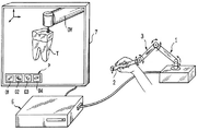
도 1에서와 같이, 이 발명은 손에 들고 쓸 수 있는 실제 요소(2)의 공간 위치에 관한 데이터를 감지하고, 스크린(7) 상에 가상 물체(T)의 3차원 표시를 하고, 상기 실제 요소(2)의 실제 공간적인 위치에 대응하는 가상 기구(OV)의 공간 표시를 제공하기 위하여 컴퓨터(6)는 공간적인 위치 데이터를 처리하고, 가상 물체(T) 상에서 작동하는 가상 기구(01-04)를 제공하고 그리고 상기 가상 물체(T)와 상기 가상 기구 사이의 상호 작용을 모델링함으로써 치과학에서 절차 이동을 얻기 위한 가상 현실 실습을 위한 시스템에 관한 것이다. 손에 들고 쓸 수 있는 요소(2)는 가상 기구(OV)가 가상 물체(T)와 상호 작용할 때 상기 실제 요소(2)를 손에 보유하고 있는 사용자에게 힘 피드백을 제공하도록 제어되는 액츄에이터를 구비하는 촉각형 사람-기계 인터페이스(IHM) 장치(1)에 속한다. 즉, 손에 들고 쓸 수 있는 실제 요소(2)는 탐침 수공구 등으로, 촉각형 인터페이스 장치(1)의 관절식 아암(3)의 자유단부에 장착되며, 촉각형 인터페이스 장치(1)는 가상 기구(OV)가 가상 물체(T)와 상호 작용할 때, 손에 들고 쓸 수 있는 실제 요소(2)에 소정의 힘을 피드백한다.1, the present invention detects data relating to the spatial position of an
국내 공개특허공보 제2003-0044909호는 치과용 장비로서 실습자가 많이 움직일 필요가 없이 한 자리에서 실습을 행하고, 다양한 가상 환자를 보유하고 있지 않으며, 실제 실습을 하는 환경과는 거리가 있는 다른 환경에서 실습을 행한다.Korean Patent Laid-Open Publication No. 2003-0044909 discloses a dental apparatus in which a practitioner does not need to move a lot and performs an exercise in one place, does not have various virtual patients, and is in a different environment Practice.
즉, 국내 공개특허공보 제2003-0044909호는 가상 방사선 장비를 구비하지 못하며, 다양한 가상 환자에 대한 실습이 불가능하며, 가상 방사선 실습시에는 가상 방사선 장비를 실제 실습자의 손으로 조작하는 실습이 어렵다.That is, Korean Patent Laid-Open Publication No. 2003-0044909 does not have a virtual radiological equipment, and it is impossible to practice various virtual patients, and it is difficult to practice the operation of a virtual radiological equipment with the hands of actual practitioners when practicing virtual radiography.
본 발명이 해결하고자 하는 과제는, 실습자가 머리 장착형 디스플레이(HMD)를 장착하고, 손에 손 장착부를 착용하고, 시청각적 가상현실상에서 제공된 가상 방사선실습 환경에서, 가상 방사선 장비를 조작하여 가상 방사선 실습을 행하되, 손 장착부로부터 실습자의 손의 위치와 각도를 핸드 모션 콘트롤러가 수신하여, 가상 방사선 장비를 동작시키게 하고, 가상 방사선 장비가 동작 됨에 따른 소정 결과를 가상으로 출력하게 하는, 가상현실 기반 방사선학 실습 장치 및 방법를 제공하는 것이다.A problem to be solved by the present invention is to provide a virtual radiological apparatus and a method of operating a virtual radiological apparatus in a virtual radiological training environment provided with a head mounted display (HMD), wearing a hand- , A virtual reality based radiology exercise in which the hand motion controller receives the position and angle of the hands of the practitioner from the hand mounting portion to cause the virtual radiological equipment to operate and to output a virtual result as a result of the operation of the virtual radiological equipment Apparatus and method.
본 발명이 해결하고자 하는 다른 과제는, 가상현실 속에서, 다양한 가상 방사선 촬영 장비를, 다양한 종류의 가상 환자 또는 다양한 가상 촬영대상에게 맞추어 조작하고, 그 실습결과를 가상으로 확인할 수 있는, 가상현실 기반 방사선학 실습 장치 및 방법를 제공하는 것이다.Another object of the present invention is to provide a virtual reality-based virtual reality apparatus capable of operating various virtual radiography apparatuses in various types of virtual patients or various virtual shooting targets in a virtual reality, And to provide a radiological training apparatus and method.
본 발명이 해결하고자 하는 다른 과제는, 소정 실습자가 행하는 가상 실습 실행 영상을 일반 디스플레이 상에도 디스플레이하여, 타 실습자 또는 교육자가 이를 볼 수 있도록 이루어진, 가상현실 기반 방사선학 실습 장치 및 방법를 제공하는 것이다.Another problem to be solved by the present invention is to provide a virtual reality-based radiological exercise apparatus and method which are displayed so that a practitioner or an educator can view a virtual exercise execution image performed by a given practitioner on a general display.
상기 과제를 해결하기 위해, 본 발명의 가상 방사선학 실습 장치는, 실습자의 머리에 장착되며, HMD(Head Mounted Display) 영상출력부로, 가상 방사선학 실습을 위해, 가상 방사선 장치를 포함하는 영상이 출력되는, HMD 머리장착부; 실습자의 손에 장착되며, 영상 상에 가상 방사선 장치를 조작하기 위해, 실습자의 손이 움직일때, 실습자의 손 움직임신호를 검출하는 손 움직임 검출부를 포함하는, HMD 손장착부; HMD 손장착부로부터 손 움직임신호를 수신하여 메인서버로 전송하고, 메인서버로 부터 수신된 영상을 HMD 머리장착부로 전송하는, HMD 제어부; HMD 제어부로부터 수신한 손 움직임신호를 수신하고, 손 움직임 신호에 따라서, 영상상에서, 실습자의 가상의 손인, 손 움직임 표시자가 움직이며, 움직여진 손 움직임 표시자를 포함하는 영상을, HMD 제어부로 전송하는 메인서버;를 포함하여 이루어진 것을 특징으로 한다.In order to solve the above problems, the virtual radiological training apparatus of the present invention is a virtual radiological training apparatus which is mounted on the head of a practitioner and is an HMD (Head Mounted Display) video output unit, for outputting an image including a virtual radiological apparatus, An HMD head mount; An HMD hand mount mounted on the hands of the practitioner and including a hand motion detection section for detecting a hand motion signal of the practitioner when the hands of the practitioner are moved to manipulate the virtual radiation apparatus on the image; An HMD controller for receiving a hand motion signal from the HMD hand mount and transmitting the hand motion signal to the main server and transmitting the image received from the main server to the HMD head mount; A virtual hand of a practitioner, a hand motion indicator moves on the image, and an image including the moved hand motion indicator is transmitted to the HMD controller in response to the hand motion signal received from the HMD controller And a main server.
HMD 머리장착부는, 메인서버로부터 HMD 제어부를 통해 수신되는 음향신호를 출력하는 이어폰;을 더 포함하고, HMD 손장착부는, 영상에서, 손 움직임 표시자와 충돌된 가상의 물체가, 상기 영상 상에서 손 움직임 표시자로 잡고 있음을 나타내게 하는, 트리거 버튼;을 더 포함한다.The HMD head mount further includes an earphone for outputting a sound signal received from the main server through the HMD control unit, wherein the HMD hand mount is configured such that, in the image, And a trigger button for indicating that it is held by a motion indicator.
손 움직임 표시자와 충돌된 가상의 물체의 부분이 가동부분인 경우에, 메인서버는, 트리거 버튼으로부터 HMD 제어부를 통해 수신된 트리거 버튼 신호가 수신되면, 영상 상에서, 가상의 물체의 가동부분이, 손 움직임 표시자의 움직임에 따라, 움직이도록 이루어진다.When the portion of the virtual object colliding with the hand movement indicator is the movable portion, when the trigger button signal received from the trigger button via the HMD control portion is received, the movable portion of the virtual object, And moves according to the movement of the hand movement indicator.
HMD 손장착부는, 영상상에서 손 움직임 표시자와 가상의 물체가 충돌될 때, 진동을 출력하는 진동발생부를 더 포함하며, HMD 머리장착부는 실습자의 머리 움직임을 검출하는 머리 움직임 검출부를 더 포함한다.The HMD hand mount further includes a vibration generator for outputting vibration when the hand movement indicator and the virtual object collide with each other on the image, and the HMD head attachment further includes a head movement detector for detecting the head movement of the practitioner.
메인서버는 머리 움직임 검출부로부터 HMD 제어부를 통해 머리움직임 신호를 수신하고, 머리움직임 신호에 따라, 영상의 시점을 변경한 영상을 생성하여, HMD 제어부로 전송한다.The main server receives a head movement signal from the head movement detection unit through the HMD control unit, generates an image in which the view point of the image is changed according to the head movement signal, and transmits the generated image to the HMD control unit.
상기 가상 방사선학 실습 장치는 실습자를 촬영하여 위치 트래킹 영상을 생성하는 카메라부를 더 포함하며, 메인서버는 카메라부로부터 HMD 제어부를 통해 수신한 위치 트래킹 영상, 머리움직임 신호, 손 움직임 신호에 따라, 영상을 생성하여 HMD 제어부로 전송한다.The virtual radiology training apparatus further includes a camera unit for photographing a practitioner to generate a position tracking image. The main server receives the position tracking image, the head movement signal, and the hand movement signal received from the camera unit through the HMD control unit, And transmits it to the HMD controller.
HMD 손장착부는, 전후좌우 이동 버튼(트랙패드)를 더 포함하며, 메인서버는, 전후좌우 이동 버튼으로부터 출력된 전후좌우 이동 버튼 신호가, HMD 제어부를 통해 수신되면, 영상 상에서, 머리움직임 신호에 의한 방향으로, 실습자가 이동함에 따라, 실습자에게 보이는 영상을 생성하여, HMD 제어부로 전송한다.The HMD hand mount further includes a forward / backward left / right movement button (track pad). When the front / rear left / right movement button signals outputted from the front / rear / left / right movement buttons are received through the HMD control unit, The moving image of the practitioner is generated and transmitted to the HMD controller.
머리움직임 신호, 위치 트래킹 영상, 손움직임 신호는, 베이스 스테이션부의 적외선 발생에 동기되어 검출된 신호이다.The head movement signal, the position tracking image, and the hand movement signal are signals detected in synchronization with the infrared ray generation of the base station unit.
실습자가, 가상 방사선 장치 또는 가상 환자를 설정하도록하는 설정부를 더 포함한다.A setting unit for allowing a practitioner to set up a virtual radiological apparatus or a virtual patient.
또한, 본 발명의 가상 방사선학 실습 장치의 구동방법는, 실습자의 머리에 장착된 HMD(Head Mounted Display) 머리장착부의 HMD 영상출력부가, 가상 방사선학 실습을 위해, 가상 방사선 장치를 포함하는 영상을 출력하고, 실습자의 손에 장착된 HMD 손장착부의 손 움직임 검출부는, 영상 상에 가상 방사선 장치를 조작하기 위해, 실습자의 손이 움직일때, 실습자의 손 움직임신호를 검출하여, HMD 제어부를 통해 메인서버의 연산처리부로 전송하고, 메인서버의 연산처리부는 수신된 손 움직임 신호에 따라서, 영상 상에서, 실습자의 가상의 손인, 손 움직임 표시자가 움직이며, 움직여진 손 움직임 표시자를 포함하는 영상을, HMD 제어부를 통해 HMD 머리장착부의 HMD 영상출력부로 출력하는 것을 특징으로 한다.According to another aspect of the present invention, there is provided a method of driving a virtual radiological training apparatus, including: outputting an image including a virtual radiological apparatus for an HMD image output unit of an HMD (Head Mounted Display) The hand motion detection section of the HMD hand mount section mounted on the hands of the practitioner detects a hand motion signal of the practitioner when the hands of the practitioner move to operate the virtual radiography apparatus on the image, And the arithmetic processing unit of the main server moves the virtual hand of the practitioner, the hand motion indicator of the practitioner, and the image including the moved hand motion indicator on the image through the HMD control unit in accordance with the received hand motion signal To the HMD image output unit of the HMD head mounting unit.
또한, 본 발명의 가상 방사선학 실습 장치의 구동방법는, 메인서버의 연산처리부는, HMD 머리장착부에 장착된 머리움직임 검출부로부터 검출된 머리움직임 신호와, HMD 손장착부의 손 움직임 검출부로부터 검출된 손움직임 신호와, 카메라부가 실습자를 촬영하여 생성한 위치 트래킹 영상을, HMD 제어부를 통해, 수신하는 신호수신단계; 메인서버의 연산처리부는 머리움직임 신호에 따라 실습자의 시야를 결정하고, 기설정된 가상실습환경의 영상을 출력하되, 실습자의 시야에 따라 조정하여 출력하고, 가상실습환경의 영상에, 손움직임 신호에 따른 위치 또는 위치 트래킹 영상신호에 따른 손 위치에, 실습자의 가상의 손인, 손움직임 표시자를 표시하는, 시야조정 및 손움직임 표시자 표시단계; 메인서버의 연산처리부는, HMD 손장착부의 입력버튼이 선택됨에 따른 입력버튼 신호가 수신되었는지 여부를 판단하고, 손움직임 표시자가 가상 방사선 장치와 충돌되었는지 여부를 판단하는, 상호적용 조건 만족여부 판단단계; 메인서버의 연산처리부는, 상호적용 조건 만족여부 판단단계에서, 입력버튼 신호가 입력되었다면, 입력버튼 신호에 따른 동작을 수행하고, 상호적용 조건 만족여부 판단단계에서, 손움직임 표시자가 가상 방사선 장치와 충돌되었다면, 진동출력 제어신호를 생성하여, HMD 제어부로 전송하는, 상호작용 실행단계;를 포함하여 이루어진다.In addition, in the driving method of the virtual radiological training apparatus of the present invention, the arithmetic processing unit of the main server may further include: a head motion signal detected from the head motion detection unit mounted on the HMD head mounting unit; a hand motion signal detected from the hand motion detection unit of the HMD hand mount; A signal receiving step of receiving, through an HMD control unit, a position tracking image generated by photographing a practitioner of a camera unit; The arithmetic processing unit of the main server determines the field of view of the practitioner according to the head movement signal, outputs the image of the virtual practice environment preset, adjusts according to the field of view of the practitioner and outputs the adjusted image, Displaying a virtual hand and a hand motion indicator of a practitioner at a hand position according to a position or position tracking video signal according to the position and / or position tracking video signal; The operation processing unit of the main server determines whether or not the input button signal corresponding to the selection of the input button of the HMD hand mount unit is received and determines whether or not the hand motion indicator has collided with the virtual radiological apparatus, ; The operation processing unit of the main server performs an operation according to the input button signal if the input button signal is input in the step of determining whether or not the mutual application condition is satisfied, And generating an oscillation output control signal if it is collided, and transmitting the oscillation output control signal to the HMD control unit.
또한, 본 발명의 가상 방사선학 실습 장치의 구동방법는, 실습자의 손움직임 신호에 따라 움직이는, 손움직임 표시자의 움직임에 따라서, 메인서버의 연산처리부는, 영상 상에서, 촬상하기 위한 위치로 이동된 가상 환자의 촬상부위에게 가상 필름을 배치하고, 가상 방사선 촬영 장치의 위치와 각도를 조절하고, 가상 방사선 촬영 장치를 구동시켜 가상 촬영하는 실습을 진행하는, 실습진행단계; 실습진행단계 후, 손움직임 표시가 가상 결과화면 모니터와 충돌되었다면, 메인서버의 연산처리부는, 손움직임 표시자에 따라서, 가상환자에게서 제거한 필름을 가상 인상하여, 가상 결과화면 모니터에 디스플레이하는, 가상 실습결과 출력단계;를 포함하여 이루어진 것을 특징으로 한다.In addition, in the driving method of the virtual radiological training apparatus of the present invention, in accordance with the motion of the hand movement indicator moving according to the hand motion signal of the practitioner, the arithmetic processing unit of the main server executes the operation of the virtual patient An actual training step of arranging a virtual film on an imaging region, adjusting a position and an angle of the virtual radiography apparatus, and driving a virtual radiography apparatus to conduct virtual radiography exercises; If the hand movement display has collided with the virtual result screen monitor after the exercise progress step, the arithmetic processing unit of the main server displays a virtual screen monitor on the virtual result screen monitor in accordance with the hand movement indicator, And outputting the result of the exercise.
실습진행단계 전에, 영상상에서, 실습자가 가상 방사선 촬영실로 이동함으로써, 메인서버의 연산처리부는, 가상 방사선 촬영실의 영상을 HMD 제어부를 통해 HMD 영상출력부로 전송하는, 가상 실습실 이동단계; 가상 실습실 이동단계 후, 메인서버의 연산처리부는, 환자선택 대화상자를 디스플레이하게 하고, 실습자가 설정한 가상 환자영상을, HMD 제어부를 통해 HMD 영상출력부로 전송하는, 가상 환자 설정단계;를 더 포함하여 이루어진다.The operation processing unit of the main server transfers the image of the virtual radiography room to the HMD image output unit through the HMD control unit by moving the practitioner to the virtual radiography room on the image before the exercise progressing step. And a virtual patient setting step of causing the operation processing unit of the main server to display a patient selection dialog box and transmitting the virtual patient image set by the practitioner to the HMD image output unit through the HMD control unit .
또한, 본 발명의 가상 방사선학 실습 장치의 구동방법는, 메인서버의 연산처리부는, 영상상에서, 손움직임 표시자가 가상물체의 가동부분과 충돌하고, HMD 손장착부의 트리거 버튼으로부터, HMD 제어부를 통해, 트리거 버튼 신호가 수신되었다면, 실습자가 가상 물체를 잡으려고 한 것으로 판단하고, HMD 손장착부의 손 움직임 검출부로부터 손 움직임신호를 수신하여, 메모리부 저장하는, 손움직임 신호 수신단계; 메인서버의 연산처리부는, HMD 손장착부의 트리거 버튼으로부터 HMD 제어부를 통해 트리거 버튼 신호가 수신되었다면, HMD 손장착부의 손 움직임 검출부로부터 현재의 손 움직임신호를 수신하고, 전의 손움직임 신호와 비교하여, 가상 물체의 가동부분을 이동시키는, 가동부분 이동단계;를 포함하여 이루어진 것을 특징으로 한다.In addition, in the driving method of the virtual radiological training apparatus of the present invention, in the image, the hand motion indicator collides with the movable part of the virtual object on the image, and from the trigger button of the HMD hand- Receiving a hand motion signal from the hand motion detection unit of the HMD hand mount unit and storing it in the memory unit when it is determined that the practitioner has tried to catch a virtual object; The operation processing unit of the main server receives the current hand motion signal from the hand motion detection unit of the HMD hand mount unit and compares it with the previous hand motion signal if a trigger button signal is received from the trigger button of the HMD hand mount unit via the HMD control unit, And moving the moving part of the virtual object.
또한, 본 발명의 가상 방사선학 실습 장치의 구동방법는, 메인서버의 연산처리부는, HMD 손장착부의 전후좌우 이동버튼(트랙패드)로부터 HMD 제어부를 통해 전후좌우 이동버튼신호가 수신되었는지를 판단하는, 전후좌우 이동버튼신호 수신여부 판단단계; 메인서버의 연산처리부는, 전후좌우 이동버튼 신호를 수신하였다면, HMD 손장착부의 손 움직임 검출부로부터의 손의 위치 및 각도값으로 이루어진 손 움직임신호를 수신하고, 손 움직임신호의 위치 및 각도에 따른 방향의 연장선 상에 지면과의 충돌지점을 계산하는, 지면 충돌지점 연산단계; 메인서버의 연산처리부는, HMD 제어부으로부터 머리의 위치 및 각도로 이루어진 머리움직임 신호를 수신하여, 실습자의 머리가 향하고 있는 방향을 결정하는, 머리움직임 신호 수신단계; 메인서버의 연산처리부는, 충돌지점 중심으로, 텔레포트 지점을 표시하고, 사용자의 바라보는 방향을 표시하는, 충돌지점 중심으로 텔레포트 지점표시단계;를 포함하여 이루어진 것을 특징으로 한다.In addition, in the driving method of the virtual radiological training apparatus of the present invention, the calculation processing unit of the main server determines whether or not the forward, backward, leftward, and rightward movement button signals are received from the front, rear, left and right movement buttons (track pads) Determining whether a left / right movement button signal is received; When receiving the forward, backward, leftward, and rightward movement button signals, the main processor of the main server receives a hand motion signal composed of hand position and angle values from the hand motion detection unit of the HMD hand mount, Calculating a point of collision with the ground on an extension line of the ground; The arithmetic processing unit of the main server receives the head motion signal composed of the position and angle of the head from the HMD control unit and determines a direction in which the head of the practitioner is heading; The arithmetic processing unit of the main server includes a teleport point display step of displaying a teleport point at the center of the collision point and displaying the direction of the user at the collision point center.
충돌지점 중심으로 텔레포트 지점표시단계 후, 메인서버의 연산처리부는, HMD 손장착부의 그랩 버튼으로부터의 그랩 버튼신호를 수신하였는지 여부를 판단는, 그랩 버튼신호 수신여부 판단단계; 그랩 버튼신호 수신여부 판단단계에서, 그랩 버튼신호를 수신하지 않았다면, 메인서버의 연산처리부는, HMD 손장착의 전후좌우 이동 버튼으로부터의 전후좌우 이동버튼 신호를 수신하였는지 여부를 판단하고, 전후좌우 이동버튼 신호를 다시 수신하지 않았다면, 지면 충돌지점 연산단계로 되돌아가는, 전후좌우 이동버튼신호 재수신여부 판단단계; 메인서버의 연산처리부는, 충돌지점 중심으로 텔레포트 지점표시단계에서 표시한, 사용자의 바라보는 방향과 텔레포트 지점으로 실습자의 방향과 위치 이동을 행한 영상을 생성하여 HMD 제어부으로 전송하는, 위치 이동실행 단계; 위치 이동실행 단계 후, 또는, 그랩 버튼신호 수신여부 판단단계에서, 그랩 버튼신호를 수신하였다면, 메인서버의 연산처리부는, 충돌지점 중심으로 텔레포트 지점표시단계에서 표시한 텔레포트 지점을 해제하는, 텔레포트 지점표시 해제단계;를 더 포함하여 이루어진다.After the teleport point display step with the center of the collision point, the arithmetic processing unit of the main server determines whether or not a grab button signal has been received to determine whether or not the grab button signal from the grab button of the HMD hand mount unit has been received; If the grab button signal has not been received, the arithmetic processing unit of the main server determines whether or not the forward, backward, leftward, and rightward movement button signals from the forward, backward, leftward, and rightward movement buttons of the HMD hand mount have been received, Determining whether the forward, backward, leftward, and rightward movement button signals are re-received, returning to the ground impact point calculation step if the button signal is not received again; The operation processing unit of the main server generates an image in which the direction and position of the practitioner are moved from the viewing direction of the user and the teleport point and displayed at the teleport point display step at the center of the collision point to transmit the image to the HMD control unit ; After receiving the grab button signal in the step of determining whether or not to receive the grab button signal, the arithmetic processing unit of the main server transmits the teleport point to the teleport point And a display releasing step.
본 발명은, 가상 실습을 실시하기 전에, 가상환자를 생성하여 디스플레이하는, 가상 방사선학 실습 장치의 구동방법에 있어서, 메인서버의 연산처리부는, MRI 스캔 데이터 또는 CT 스캔 데이터로 이루어진 의료영상 데이터를 영상처리서버로 전송하는 단계; 영상처리서버는, 심층인공신경망구조를 사용하여, 메인서버로부터 수신한 의료영상 데이터의 영상분할을 행하고, 분할된 영상을 이용하여 장기 또는 조직의 메쉬 데이터(표면정보)를 산출하고, 산출된 장기 또는 조직의 표면정보(메쉬 데이터)를 메인서버로 전송하는 단계; 메인서버는 수신된 표면정보(메쉬 데이터)를 가상환자의 소정부분을, 3D모델의 표면정보(메쉬 데이터)로 변경하여, 가상환자를 디스플레이하는 단계;를 포함하는 것을 특징으로 한다.The present invention is a driving method of a virtual radiology training apparatus for generating and displaying a virtual patient before performing a virtual exercise, wherein the operation processing unit of the main server is adapted to display medical image data composed of MRI scan data or CT scan data To a processing server; The image processing server performs image segmentation of the medical image data received from the main server using the in-depth artificial neural network structure, calculates mesh data (surface information) of the organ or tissue using the divided images, Or the surface information of the organization (mesh data) to the main server; And the main server is characterized by including a step of displaying the virtual patient by changing the received surface information (mesh data) into the surface information (mesh data) of the 3D model of a predetermined part of the virtual patient.
또한, 본 발명은, 가상 실습이 끝나면, 메인서버가 가상 방사선 촬영 결과화면을 생성하는, 가상 방사선학 실습 장치의 구동방법에 있어서, 메인서버의 연산처리부는, 촬영대상, 촬영기, 필름의 상대적 위치 및 각도 값을 읽어들이는, 촬영대상과 촬영기와 필름의 상대적 위치 읽기단계; 메인서버의 연산처리부는 설정된 환자의 CT 스캔 데이터를 데이터베이스로부터 읽어들이는, CT 스캔 데이터 로드단계;메인서버의 연산처리부는 볼륨렌더링을 통한 CT 스캔데이터의 3차원 모델링을 행하는, CT 스캔데이터의 3차원 모델링단계; 메인서버의 연산처리부는 CT 스캔데이터의 3차원 모델링단계에서 생성된 3차원 모델과, 필름 및 촬영기의 상대적 위치에 따라, 촬영기와 필름 사이의 상기 3차원 모델의 3차원 데이터를 2차원 평면에 투과시켜 방사선 사진을 생성하는, 방사선 사진 생성단계;를 포함하여 이루어진 것을 특징으로 한다.The present invention further provides a driving method of a virtual radiology training apparatus wherein a main server generates a virtual radiography result screen after a virtual training session is completed, wherein an arithmetic processing unit of the main server calculates a relative position between a shooting target, Reading the relative position of the object to be photographed with the film to read the angle value; The computation processing unit of the main server loads the CT scan data of the set patient from the database, and the operation processing unit of the main server performs the 3D modeling of the CT scan data through the volume rendering. Dimensional modeling step; The operation processing unit of the main server transmits the three-dimensional data of the three-dimensional model between the camera and the film to the two-dimensional plane according to the three-dimensional model generated in the three-dimensional modeling step of the CT scan data and the relative positions of the film and the camera. And generating a radiographic image by radiographing the radiographic image.
또한, 본 발명은, 가상 실습이 끝나면, 메인서버가 가상 방사선 촬영 결과화면을 생성하는, 가상 방사선학 실습 장치의 구동방법에 있어서, 메인서버의 연산처리부는, 촬영대상, 촬영기, 필름의 상대적 위치 및 각도 값을 읽어들이는, 촬영대상과 촬영기와 필름의 상대적 위치 읽기단계; 메인서버의 연산처리부는, 기 설정된 환자의 타겟부위 방사선 사진을 데이터베이스로부터 읽어들이는, 방사선사진 로드단계; 메인서버의 연산처리부는, 방사선사진 로드단계에 읽어들인 타겟부위 방사선 사진인, 원본 방사선 사진을 투영하여, 촬영기 평행방향으로 이동하고, 투영에 따른 사진 크기를 확대 또는 축소하는, 원본 방사선 사진의 크기 조절단계; 메인서버의 연산처리부는, 원본 방사선 사진의 크기 조절단계 후, 투영사진과 필름이, 접점이 있는지 여부를 판단하고, 접점이 없다면, 원본 방사선 사진의 크기 조절단계로 되돌아가는, 접점존재 여부판단단계; 접점존재 여부판단단계에서 접점이 있다면, 메인서버의 연산처리부는, 상기 접점의 투영사진 픽셀값을, 결과사진을 저장하는 버퍼에, 복사하는, 픽셀값 저장단계;를 포함하여 이루어진 것을 특징으로 한다.The present invention further provides a driving method of a virtual radiology training apparatus wherein a main server generates a virtual radiography result screen after a virtual training session is completed, wherein an arithmetic processing unit of the main server calculates a relative position between a shooting target, Reading the relative position of the object to be photographed with the film to read the angle value; The arithmetic processing unit of the main server includes: a radiographic photographing step of reading a target region radiograph of a predetermined patient from a database; The operation processing unit of the main server may be configured to project the original radiographic image, which is the target region radiographic image read in the radiographic image loading step, in the parallel direction of the image capturing apparatus, to enlarge or reduce the size of the image according to the projection, An adjusting step; The arithmetic processing unit of the main server determines whether or not there is a contact between the projection photograph and the film after the size adjustment step of the original radiograph and returns to the size adjustment step of the original radiograph if there is no contact, ; And a pixel value storing step of copying the projected picture pixel value of the contact point to a buffer storing the result picture if the contact point exists in the step of determining whether or not the contact point exists .
상기 가상 방사선학 실습 장치의 구동방법은, 투영사진이 필름영역을 벗어났는지 여부를 판단하고, 벗어나지 않았다면, 원본 방사선 사진의 크기 조절단계로 되돌아가고, 투영사진이 필름영역을 벗어 났다면, 종료하는, 필름영역을 벗어났는지 여부 판단단계를 더 포함하여 이루어진다.The driving method of the virtual radiological training apparatus includes the steps of determining whether the projected picture is out of the film area and returning to the size adjustment step of the original radiographic picture if it has not departed, And judging whether or not the film is out of the film area.
본 발명의 가상현실 기반 방사선학 실습 장치 및 방법는, 실습자가 머리 장착형 디스플레이(HMD)를 장착하고, 손에 손 장착부를 착용하고, 시청각적 가상현실상에서 제공된 가상 방사선실습 환경에서, 가상 방사선 촬영 장비를 조작하여 가상 방사선 촬영 실습을 행하되, 손 장착부로부터 실습자의 손의 위치와 각도를 핸드 모션 콘트롤러가 수신하여, 가상 방사선 촬영 장비를 동작시키게 하고, 가상 방사선 촬영 장비가 동작 됨에 따른 소정 결과를 가상으로 출력하게 한다. 따라서, 본 발명은 실습자가 실제 환경에서 실제적인 실습을 행하는 것과 같은 실습을 행하게 하며, 실습자와 교육자가 방사선에 노출될 우려가 없다.A virtual reality-based radiological training apparatus and method of the present invention is characterized in that a practitioner mounts a head-mounted display (HMD), wears a hand mount on a hand, and operates the virtual radiography equipment in a virtual radiation training environment provided on an audiovisual virtual reality The hand motion controller receives the position and the angle of the hands of the practitioner from the hand mount unit to operate the virtual radiography apparatus and outputs a virtual result of the operation of the virtual radiography apparatus do. Therefore, the present invention allows the practitioner to perform an exercise such as practicing an actual practice in a real environment, and there is no fear that the practitioner and the educator are exposed to radiation.
본 발명은, 가상현실 속에서, 다양한 가상 방사선 촬영 장비를, 다양한 종류의 가상 환자 또는 다양한 가상 촬영 대상에게 맞추어 조작하고, 그 실습 결과를 가상으로 확인할 수 있다.According to the present invention, various virtual radiographic imaging apparatuses can be operated in accordance with various types of virtual patients or various virtual imaging targets in a virtual reality, and the result of the practice can be virtually confirmed.
즉, 본 발명은, 기존 방사선학 실습에서 실제 방사선 장비와 마네킹을 이용하여 행하던 실습 방식을, 가상현실 속에서 가상의 촬영장비와 다양한 가상의 환자를 통하여 실습을 실시하도록 하여, 기존 방사선학 실습 방식이 가지고 있던 문제점들인 방사선에 직접적인 노출, 실습실 운영에 들어가는 높은 비용, 제한적인 실습 경험을 해결 할 수 있다.In other words, the present invention is based on the fact that in the existing radiology practice, the practice performed using the actual radiological equipment and the mannequin is practiced in the virtual reality through the virtual imaging equipment and various virtual patients, Exposure to radiation problems, high costs for laboratory operation, and limited practical experience can be solved.
본 발명은, 구강 방사선할 실습(Oral Radiology Practice) 등에도 적용 가능하다.The present invention is also applicable to Oral Radiology Practice and the like.
또한, 본 발명은, 소정 실습자가 행하는 가상 실습 실행 영상을 일반 디스플레이 상에도 디스플레이하여, 타 실습자 또는 교육자가 이를 볼 수 있도록 이루어져, 실습자는 가상 실습을 행하되, 교육자의 교육에 따라 실습이 가능하며, 타 실습자의 조언도 들을 수 있다.In addition, the present invention displays a virtual exercise execution video performed by a specific practitioner on a general display so that the practitioner or an educator can view the exercise. The practitioner can perform a virtual exercise, , And other practitioners' advice.
도 1은 국내 공개특허공보 제2003-0044909호의 가상 현실 실습 시스템의 블록도이다.
도 2는 본 발명의 가상현실 기반 방사선학 실습 장치를 개략적으로 설명하기 위한 모식도이다.
도 3은 도 2의 가상현실 기반 방사선학 실습 장치의 구동방법을 개략적으로 설명하기 위한 모식도이다.
도 4는 도 2의 HMD 손장착부의 일예이다.
도 5는 도 2의 가상현실 기반 방사선학 실습 장치의 구성을 설명하기 위한 블럭도이다.
도 6은 도 5의 메인서버의 연산처리부의 기본 동작을 설명하기 위한 흐름도이다.
도 7은 방사선 촬영장치를 이용한 실습모드에서, 도 5의 메인서버의 연산처리부의 동작을 설명하기 위한 흐름도이다.
도 8은 가상실습환경에서 물건을 잡을 때에 대한, 도 5의 메인서버의 연산처리부의 동작을 설명하기 위한 흐름도이다.
도 9는 도 5의 메인서버의 연산처리부에서, 가상 실습공간에서 텔레포트(실습자의 위치 이동) 처리과정을 나타내는 흐름도이다.
도 10은 본 발명의 가상 방사선학 실습 장치를 이용한 가상 실습시, 방사선 촬영 결과화면의 연산과정의 일예를 설명하는 흐름도이다.
도 11은 본 발명의 가상 방사선학 실습 장치를 이용한 가상 실습시, 방사선 촬영 결과화면의 연산과정의 다른 일예를 설명하는 흐름도이다.
도 12 및 도 13은 도 2의 가상현실 기반 방사선학 실습 장치에서, 가상 방사선 장치가 디지털 엑스레이 기기인 경우의 모식도이다.
도 14 및 도 15는 도 2의 가상현실 기반 방사선학 실습 장치에서, 가상 방사선 장치가 혈관조영술 기기인 경우의 모식도이다.
도 16은 도 2의 가상현실 기반 방사선학 실습 장치에서, 가상 방사선 장치가 CT 스캐너인 경우의 모식도이다. 1 is a block diagram of a virtual reality training system of Korean Patent Laid-Open Publication No. 2003-0044909.
2 is a schematic diagram for schematically explaining a virtual reality-based radiological training apparatus of the present invention.
FIG. 3 is a schematic diagram for explaining a driving method of the virtual reality-based radiological training apparatus of FIG. 2; FIG.
4 is an example of the HMD hand mount of Fig.
FIG. 5 is a block diagram for explaining the configuration of the virtual reality-based radiological training apparatus of FIG. 2;
6 is a flowchart for explaining a basic operation of the operation processing unit of the main server of FIG.
Fig. 7 is a flowchart for explaining the operation of the arithmetic processing unit of the main server of Fig. 5 in the practice mode using the radiographic apparatus.
Fig. 8 is a flowchart for explaining the operation of the arithmetic processing unit of the main server of Fig. 5 when an object is caught in a virtual laboratory environment.
FIG. 9 is a flowchart showing a process of teleporting (movement of a practitioner's position) in a virtual exercise space in the operation processing unit of the main server of FIG. 5;
10 is a flowchart for explaining an example of a calculation process of a radiographing result screen in a virtual practice using a virtual radiograph exercise apparatus according to the present invention.
11 is a flowchart for explaining another example of the calculation process of the radiographing result screen in the virtual practice using the virtual radiograph exercise apparatus of the present invention.
Figs. 12 and 13 are schematic diagrams in the case where the virtual radiological apparatus is a digital x-ray apparatus in the virtual reality-based radiological exercise apparatus of Fig.
FIGS. 14 and 15 are schematic diagrams in the case of the virtual reality-based radiological exercise apparatus of FIG. 2, in which the virtual radiological apparatus is an angiography apparatus.
FIG. 16 is a schematic diagram of the virtual reality-based radiological exercise apparatus of FIG. 2, in which the virtual radiological apparatus is a CT scanner.
이하, 본 발명의 가상현실 기반 방사선학 실습 장치 및 방법을 첨부된 도면을 참조하여 상세히 설명한다.DETAILED DESCRIPTION OF THE PREFERRED EMBODIMENTS Hereinafter, a virtual reality-based radiological training apparatus and method according to the present invention will be described in detail with reference to the accompanying drawings.
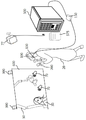
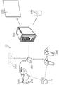
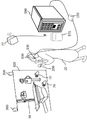
도 2는 본 발명의 가상현실 기반 가상 방사선학 실습 장치를 개략적으로 설명하기 위한 모식도이고, 도 3은 도 2의 가상현실 기반 가상 방사선학 실습 장치의 구동방법을 개략적으로 설명하기 위한 모식도이다.FIG. 2 is a schematic diagram for explaining a virtual reality-based virtual radiological training apparatus of the present invention, and FIG. 3 is a schematic diagram for schematically explaining a driving method of a virtual reality-based virtual radiological training apparatus of FIG.
본 발명에서, 베이스 스테이션부(77), HMD 머리장착부(100), HMD제어부(링크박스)(150), HMD 손장착부(200), 카메라부(300)는 하나의 세트, 즉, HMD 세트(76)로 이루어진다. 여기서, HMD 세트(76)는 시판되는 것을 사용할 수도 있다.In the present invention, the
도 2에서와 같이, 실습자(20)는 머리에 HMD 머리장착부(100)를 착용하고, 손에는 HMD 손장착부(핸드 모션 콘트롤러)(200)를 착용하거나 손에 쥐고, HMD 머리장착부(100)에 디스플레이 되는 영상을 보면서 그리고 HMD 머리장착부(100) 연결된 이어폰(130)을 통해 소리(음향)를 들으면서, 강의를 듣거나, 실습을 행할 수 있다. 이때, HMD 머리장착부(100)에 디스플레이되는 영상은 외부에 위치된 디스플레이부(600)에 그대로 디스플레이 되고, 또한 HMD 머리장착부(100) 연결된 이어폰(130)의 소리는 외부에 위치된 스피커부(575)를 통해 그대로 출력된다. As shown in FIG. 2, the
카메라부(300)는 하나 이상의 위치 트래킹(모션 트래킹) 센싱 카메라를 포함하여 이루어지며, 실습자(20)의 움직임 영상, 즉, 실습자 영상을 촬영하여 HMD제어부(150)로 전송하며, HMD제어부(150)는 이를 메인서버(500)로 전송하거나, 실습자 영상으로부터 사용자의 움직임에 따른 위치 트래킹(모션 트래킹) 신호를 검출하여 메인서버(500)로 전송한다.The
HMD 머리장착부(100)와 디스플레이부(600)에는 손형태의 손 움직임 표시자(70)를 디스플레이하며, 손 움직임 표시자(70)는 실습자(20)의 손, 즉, HMD 손장착부(200)의 움직임 신호에 대응하여, 디스플레이부(600)의 화면상, 즉, 가상 실습환경에서, 움직여지고, 손 움직임 표시자(70의 움직임에 대응하여, 디스플레이된 가상 방사선 장치(50)의 소정 가동부분이 움직이거나(또는 이동하거나), 아니면, 디스플레이된 소정 설정 스위치가 선택될 수 있다. 이때, 실습자(20)의 손 움직임 표시자(70)가 가상 방사선 장치(50) 등과 접촉되거나, 가상 방사선 장치(50) 등을 잡았을 때, 이를 나타내는 진동을 HMD 손장착부(200)의 진동발생부(230)을 통해 느끼게 된다.The
HMD 머리장착부(100)는 메인서버(500)로부터 HMD제어부(150)를 통해 수신된 영상신호 및 음향신호를 HMD 영상출력부(120) 및 이어폰(130)으로 출력하고, HMD 머리장착부(100) 상에 장착된 머리움직임 검출부(110)로부터 검출된 머리움직임 신호를 HMD제어부(150)를 통해 메인서버(500)로 전송한다. 여기서, 머리움직임 신호는 실습자(20)가 향하는 방향 또는 실습자(20)가 처다보고 있는 방향을 나타내는 것이다.The HMD
HMD 머리장착부(100)와 디스플레이부(600)에는 사용자가 선택한 실습모드에 따라서, 메인서버(500)로부터 HMD제어부(150)을 통해 수신된 가상 방사선 장치(50)가 디스플레이되고, 또한, 가상 방사선학 실습 장치의 설정부에서 사용자의 설정에 따라 메인서버(500)로부터 HMD제어부(150)을 통해 수신된 소정 가상 환자(30)가 디스플레이될 수 있다. The HMD
여기서, 도 2의 가상 방사선 장치(50)는 구내방사선 촬영기 (Intraoral X-ray Machine)를 나타내고 있으나, 이로써 본 발명을 한정하기 위한 것이 아님을 밝혀둔다. 가상 방사선 장치(50)는 가상 방사선 치료장치이거나 또는 가상 방사선 촬영장치로, 디지털 엑스레이 기기(Digital X-ray Machine), 혈관조영술 기기 (Angiography Machine), CT 스캐너 (CT Scanner), MRI 기기 (MRI Machine), 구내방사선 촬영기 (Intraoral X-ray Machine), 파노라마 방사선 촬영기, 구외방사선촬영기 (Panoramic Rapdiograph machine), 유방촬영기 (Mammography Machine) 등 일 수 있다.Here, the virtual
예를들어, 가상 방사선 장치(50)가 디지털 엑스레이 기기(Digital X-ray Machine)인 경우의 가상현실 기반 가상 방사선학 실습 장치의 모식도는 도 12 및 도 13과 같다. 또한, 가상 방사선 장치(50)가 혈관조영술 기기 (Angiography Machine)인 경우의 가상현실 기반 가상 방사선학 실습 장치의 모식도는 도 14 및 도 15와 같다. 또한, 가상 방사선 장치(50)가 CT 스캐너인 경우의 가상현실 기반 가상 방사선학 실습 장치의 모식도는 도 16과 같다.For example, a schematic diagram of a virtual reality-based virtual radiological training apparatus when the virtual
HMD 머리장착부(100)와 연결된 이어폰(130)은 메인서버(500)로부터 HMD제어부(150)을 통해 수신된 음향신호가 출력되고, 이 음향신호는 메인서버(500)로부터 스피커부(575)로도 전달되어, 스피커부(575)를 통해서도 들을 수 있다.The
HMD 손장착부(200)는 손움직임 검출부(210)에서 검출된 손 움직임 신호를 HMD제어부(150)을 통해 메인서버(500)로 전송하며, 또한 메인서버(500)로부터 HMD제어부(150)을 통해 수신된 진동제어신호에 따라 진동발생부(230)가 구동된다. The HMD
손움직임 검출부(210) 및 머리움직임 검출부(110)는 베이스 스테이션부(77)로부터 적외선이 발생됨에 따라 이에 동기하여, 손 움직임 신호 및 머리 움직임 신호를 검출한다.The hand
메인서버(500)는 수신된 손 움직임 신호, 머리움직임 신호, 실습자 영상을 이용하여, 움직이게 하고자 하는 가상 방사선 장치(50)의 가동부분을 설정하고, 손 움직임 신호에 대응하여 설정된 가동부분을 움직이게 하는 영상을 생성하여 HMD 머리장착부(100)와 디스플레이부(600)로 전송한다.The
또는, 메인서버(500)는 수신된 손 움직임 신호, 입력버튼 신호, 머리움직임 신호, 실습자 영상을 이용하여, 가상 방사선 장치(50)의 설정부 또는 가상 방사선학 실습 장치의 설정부에서, 소정 스위치를 선택하고, 선택된 스위치의 구동을 개시하거나 종료하게 한다. 이들 스위치들은 토굴 스위치로 이루어질 수 있다.Alternatively, the
도 4는 도 2의 HMD 손장착부의 일예이다.4 is an example of the HMD hand mount of Fig.
도 2의 HMD 손장착부(200)는 시판되는 것으로, 그 상면에 전후좌우 이동 버튼(215), 전원 온(On)/오프(Off) 버튼(237), 메뉴 버튼(235)을 포함하며, 그 하면의 일측에 트리거 버튼(217)을 구비한다. 전후좌우 이동 버튼(215), 전원 온(On)/오프(Off) 버튼(237), 메뉴 버튼(235)은 엄지손가락을 사용할 수 있으며, 트리거 버튼(217)은 집게손가락을 사용할 수 있다.The
도 5는 도 2의 가상현실 기반 가상 방사선학 실습 장치의 구성을 설명하기 위한 블럭도로, 베이스 스테이션부(77), HMD 머리장착부(100), HMD제어부(150), HMD 손장착부(200), 메인서버(500), 스피커부(575), 디스플레이부(600), 의료영상처리 서버(700)을 포함하여 이루어진다.FIG. 5 is a block diagram illustrating a configuration of a virtual reality-based virtual radiograph exercise apparatus of FIG. 2, which includes a
베이스 스테이션부(77)는 소정 주기로 적외선을 출력하는 하나 이상의 베이스 스테이션으로 이루어지며, 머리움직임 검출부(110)와 손 움직임 검출부(210)는 베이스 스테이션부(77)에서 출사되는 적외선에 동기되어 신호를 검출한다.The
HMD 머리장착부(100)는 실습자(20)에게 가상 실습환경을 제공하며, 현재 실습자의 얼굴이 향한 방향을 위해 머리 움직임신호를 검출하여, HMD제어부(150)를 통해 메인서버(500)로 전송하기 위한 수단이다. HMD 머리장착부(100)는 머리움직임 검출부(110), HMD 영상출력부(120), 이어폰(130)을 포함하여 이루어진다.The HMD
머리움직임 검출부(110)는 HMD 머리장착부(100)에 머리움직임 검출센서(미도시)가 장착되어, 머리움직임 신호를 검출하여, HMD제어부(150)의 머리움직임 신호 전처리부(160)로 전송한다. 머리움직임 신호는 머리의 위치신호(X, Y, Z)와 머리 회전의 각도 신호로 이루질 수 있다. 여기서, 머리움직임 검출센서로는 자이로센서, 가속도 센서 등으로 이루어질 수 있다.The head
HMD 영상출력부(120)는 영상출력 제어부(170)를 통해 수신된 영상신호를 출력한다.The HMD
이어폰(130)은 음향출력 제어부(177)를 통해 수신된 음향신호를 출력한다. 이어폰(130)을 통해 출력되는 음향은 주로 강의 자료(음향) 등일 수 있다. The
HMD 손장착부(200)는 손 움직임 검출부(210), 입력버튼(220), 진동발생부(230)를 구비하며, 손 움직임 검출부(210)를 이용하여 실습자(20)의 손 움직임 신호를 검출하여, 가상 실습환경(영상) 상에 디스플레이되는 손 움직임 표시자(70)를 이동하여 가상 실습을 행하게 하며, 또한, 입력버튼(220)을 통해, 실습자(20)가 가상 영상 상에 디스플레이되는 가상 방사선 장치(50)의 설정부 또는 가상 방사선학 실습 장치의 설정부 등에서 소정 스위치 등을 선택할 수 있게 하고, 진동발생부(230)를 이용하여, 실습자(20)가 가상 실습환경 상에 소정 물체에 접촉하거나, 소정 물체를 잡았을 때의 느낌을, 진동을 통해 인지하도록 이루어져 있다.The HMD
손 움직임 검출부(210)는 손 움직임 검출센서(미도시)가 장착되어, 손 움직임 신호를 검출하여, 무선으로 HMD 제어부(150)의 제1 데이터송수신부(250)을 통해 손 움직임 신호 전처리부(260)으로 전송한다. 여기서, 손 움직임 신호는 손의 위치신호(X, Y, Z)와 손 회전의 각도 신호로 이루질 수 있다. 여기서, 손 움직임 검출센서로는 자이로센서, 가속도 센서 등으로 이루어질 수 있다.The hand
입력버튼부(220)는 HMD 손장착부(200)에 전후좌우 이동 버튼(215), 트리거 버튼(217), 전원 온(On)/오프(Off) 버튼(237), 메뉴 버튼(235) 등을 구비하여, 실습자(20)의 이동(예를들어, 실습자(20)가, 가상실습환경 상에서, 가상 촬영실 밖으로 나오거나 할때의 이동) 시에 사용하거나, 또는 가상 방사선 장치(50)의 설정부 또는 가상 방사선학 실습 장치의 설정부 등에서 소정 스위치 등을 선택할 때 사용한다. 트리거 버튼(217)은 실습자가 가상 물체 등을 잡으려고 할 때 선택하는 버튼이다. 즉, 실습자는 가상 물체를 잡고 있는 동안에는 트리거 버튼을 계속 누르고 있으며, 따라서 그동안에는 가상 물체를 움직임 표시자가 잡고 있는 것이 된다.The
진동발생부(230)는 HMD제어부(150)의 진동출력 제어부(280)로부터 제1 데이터송수신부(250)을 통해 수신된 진동발생부 구동신호에 따라 진동을 발생한다. 진동발생부(230)는 HMD 손장착부(200)에서 손바닥이 접촉되는 부분에 위치된다.The
카메라부(300)는 실습자(20)의 움직임 영상을 촬영하여, 실습자 영상, 즉, 실습자의 위치 트래킹(모션 트래킹) 영상을 HMD제어부(150)의 영상신호 전처리부(310)로 전송한다. 카메라부(300)는 디스플레이부(600)와 실습자(20)의 움직임을 촬상가능한 곳에 장착되며, 카메라부(300)는 하나 이상의 카메라로 이루어질 수 있으며, 바람직하게는 2대의 카메라로 이루어질 수 있다. 카메라부(300)는 위치 트래킹(모션 트래킹) 센싱부이다. 경우에 따라서 카메라부(300)는 뎁스 카메라로 이루어질 수 있다.The
HMD제어부(150)는 머리 움직임 신호 전처리부(160), 영상출력 제어부(170), 음향출력 제어부(177), 손움직임 신호 전처리부(260), 입력버튼신호 전처리부(270), 진동출력제어부(280), 영상신호 전처리부(310)을 포함하여 이루어진다.The
도 2에서는, HMD제어부(150)와 HMD 머리장착부(100)의 연결은 유선으로 이루어지고, HMD제어부(150)와 HMD 손장착부(200)의 연결은 무선으로 이루어지고, HMD제어부(150)와 메인서버(500)는 유선으로 연결되어 있으나, 이로써 본 발명을 한정하기 위한 것이 아님을 밝혀둔다. 즉, HMD제어부(150)와 HMD 머리장착부(100)의 연결이 무선으로 이루어지거나, 또는 HMD제어부(150)와 메인서버(500)의 연결이 무선으로 이루어질 수 있다. 2, the connection between the
머리 움직임 신호 전처리부(160)는 머리움직임 검출부(110)에서 검출된 머리 움직임 신호를 증폭하거나 잡음을 제거하며, 디지탈신호로 변경하고, 디지탈신호로 변경된 머리움직임 신호를 HMD제어부(150)의 연산처리부(350)로 전송한다.The head motion
영상출력 제어부(170)는 HMD제어부(150)의 연산처리부(350)로 부터, 영상신호와 영상출력 제어신호를 수신하여, HMD 영상출력부(120)가 상기 영상신호를 출력하도록 제어한다.The video
음향출력 제어부(177)는 HMD제어부(150)의 연산처리부(350)로 부터, 음향신호와 음향출력 제어신호를 수신하여, 이어폰(130)이 상기 음향신호를 출력하도록 제어한다.The sound
손움직임 신호 전처리부(260)는 손 움직임 검출부(210)에서 검출된 손 움직임 신호를 제1 데이터송수신부(250)을 통해 수신하여, 증폭하거나 잡음을 제거하며, 디지탈신호로 변경하고, 디지탈신호로 변경된 손움직임 신호를 HMD제어부(150)의 연산처리부(350)로 전송한다.The hand motion
입력버튼신호 전처리부(270)는 입력버튼부(220)로부터 제1 데이터송수신부(250)을 통해 버튼입력신호를 수신하고, 디지탈신호로 변환하여 HMD제어부(150)의 연산처리부(350)로 전송한다.The input button
진동출력 제어부(280)는 HMD제어부(150)의 연산처리부(350)로부터, 수신된 진동출력 제어신호를 수신에 따라, 진동발생부(230)를 구동시키기 위한 진동발생부 구동신호를 생성하여, 제1 데이터송수신부(250)을 통해 진동발생부(230)로 전송한다.The vibration
영상신호 전처리부(310)은 카메라부(300)로부터 수신된 실습자 영상, 즉, 실습자의 위치 트래킹(모션 트래킹) 영상을 디지탈신호로 변경하여 HMD제어부(150)의 연산처리부(350)로 전송한다.The image
연산처리부(350)은 수신된 머리움직임 신호, 손움직임 신호, 입력버튼 신호, 실습자 영상(실습자의 위치 트래킹 영상)을 수신하여, 메인서버(500)로 전송하기 위한 신호로 변환하여, 제2 데이터송수신부(370)을 통해 메인서버(500)으로 전송한다. 또한, 연산처리부(350)는 메인서버(500)로부터 수신된 영상신호, 음향신호를, 영상출력 제어부(170), 음향출력 제어부(177)를 통해, HMD 영상출력부(120, 이어폰(130)으로 출력하게 한다. The
즉, 베이스 스테이션부(77)에서 일정하게 적외선 신호를 내보내면, HMD 머리장착부(100)의 적외선 검출센서(미도시)는 상기 적외선 신호를 검출하고, 상기 적외선 신호가 검출되면, 머리움직임 검출부(110)에서 검출된 머리움직임 신호가 HMD제어부(150)의 머리 움직임 신호 전처리부(160)로 전송되고, 머리 움직임 신호 전처리부(160)는 머리움직임 신호를 전처리하고, 전처리된 머리움직임 신호(또는, 머리움직임 신호 및 상기 적외선 신호)를 연산처리부(350) 및 제2 데이터 송수신부(370)을 통해, 메인서버(500)로 전송한다. 또한, HMD 손장착부(200)의 적외선 검출센서(미도시)도 상기 적외선 신호를 검출하여, 적외선 신호가 검출되면, 손움직임 검출부(210)에서 검출된 손움직임 신호와 상기 적외선 신호가, 제1 데이터 송수신부(250)을 통해, HMD제어부(150)의 손움직임신호 전처리부(260)로 전송되고, 손움직임신호 전처리부(260)는 손움직임 신호를 전처리하고, 전처리된 손움직임 신호(또는, 손움직임 신호 및 상기 적외선 신호)를 연산처리부(350) 및 제2 데이터 송수신부(370)을 통해, 메인서버(500)로 전송한다. That is, when the infrared ray signal is constantly outputted from the
메인서버(500)는 가상 방사선학 실습 장치(10)의 전반적인 제어를 담당한다. The
메인서버(500)는 HMD제어부(150)로부터 머리움직임 신호를 수신하고, 손움직임 신호, 입력버튼신호, 실습자 영상을 수신하고, 이들 신호로부터, 움직이게 하고자 하는 가상 방사선 장치(50)의 가동부분을 설정하고, 손 움직임 신호에 대응하여 설정된 가동부분을 움직이게 하는 영상을 생성하여 출력하게 한다. The
또한, 메인서버(500)는 사용자에 의해 설정된 가상환자(30)를 읽어들여 디스플레이부(600)에 디스플레이하되, 가상환자(30)는 특정 장기 또는 조직에 문제를 가진 환자로, 의료영상처리 서버(700)에서 생성된 특정 장기 또는 조직과 관련된 메쉬 데이터를 수신하여, 가상환자(30)에 적용시켜 디스플레이 한다.The
메인서버(500)는 데이터 송수신부(510), 연산처리부(550), 데이터베이스(560), 메모리부(570)을 포함하여 이루어진다.The
데이터 송수신부(510)는 HMD제어부(150)로부터 수신된 신호를 연산처리부(550)으로 전달하기 위한 수단이다. 경우에 따라서는 데이터 송수신부(510)는 생략될 수 있다.The data transmission /
연산처리부(550)는 머리움직임 신호에 따라 가상 방사선 장치(50) 및 가상환자(30)을 포함하는 이미지의 시점을 결정하여 디스플레이하게 한다. 그리고, 연산처리부(550)는 카메라부(300)의 실습자 영상, 즉 실습자의 위치 트래킹영상을 이용하여, 사용자의 손의 위치를 결정하고, 상기 손의 위치에 맞추어 손형태의 손 움직임 표시자(70)를 상기 이미지에 디스플레이한다. 그리고, 연산처리부(550)는 손 움직임 신호에 따라, 손 움직임 표시자(70)를 이동하게(움직이게) 한다. The
만약, 상기 이미지 상에서 손 움직임 표시자(70)가 가상 방사선 장치(50)의 가동부분에 접촉되었다면, 연산처리부(550)는 가상 방사선 장치(50)의 가동부분을 손(양손 또는 한 손)으로 잡고 있는 것으로 인식한다. 만약, 상기 이미지 상에서 손 움직임 표시자(70)가 가상 방사선 장치(50)의 가동부분에 접촉된 상태로 이동되었다면, 연산처리부(550)는 손 움직임 표시자(70)의 이동에 따라, 가상 방사선 장치(50)의 가동부분도 이동하도록 하는 영상을 생성하여 HMD 머리장착부(100)와 디스플레이부(600)로 전송하여 출력하게 한다. 이때, 손 움직임 표시자(70)가 가상 방사선 장치(50)의 가동부분에 접촉된 상태이라면, 진동출력 제어신호를 생성하여, 데이터 송수신부(510)를 통해, HMD 제어부(150)으로 전송한다.If the
또한, 연산처리부(550)는 입력버튼 신호가 수신되었다면, HMD 머리장착부(100)와 디스플레이부(600)에 디스플레이되는, 가상 방사선학 실습 장치(10)의 설정부, 또는 가상 방사선 장치(50)의 설정부의, 다수의 스위치 중에, 사용자가 선택한 소정 스위치를 인식한다. 즉, 연산처리부(550)는 입력버튼 신호가 수신되었다면, 카메라부(300)으로부터 수신된 영상을 통해 사용자가 선택한 스위치를 찾고(검출하고), 이렇게 검출된 스위치를 누른 것으로 인식한다. The
여기서, 가상 방사선학 실습 장치(10)의 설정부, 또는 가상 방사선 장치(50)의 설정부의, 다수의 스위치는 토굴(toggle)스위치로서, 처음 누르면 그 스위치를 온(ON)한 것이 되고, 다음에 다시 누르면 그 스위치를 오프(OFF)한 것이 된다.Here, a plurality of switches of the setting unit of the virtual
즉, 연산처리부(550)는 입력버튼 신호, 카메라부(300)의 실습자 영상을 이용하여, 가상 방사선 장치(50)의 설정부 또는 가상 방사선학 실습 장치의 설정부에서, 소정 스위치를 선택하고, 선택된 스위치의 구동을 개시하거나 종료하게 한다. That is, the
데이터베이스(560)는 다양한 가상 방사선 장치 영상, 다양한 가상 환자 영상들을 저장하고 있다. The
메모리부(570)은 연산처리부(550)로부터 수신된 출력된 신호들을 저징하며, 연산처리부(550)에서 연산과정 중 데이터 등의 임시저장을 위해 사용된다.The
스피커부(575)는 메인서버(500)의 연산처리부(550)로부터 수신된 음향신호를 출력하며, 여기서 출력되는 음향신호는 이어폰(130)에서 출력되는 음향신호와 같다.The
디스플레이부(600)는 피실습자 또는 교육자가 보기 위한 디스플레이부로서, 메인서버(500)의 연산처리부(550)로부터 수신된 영상신호를 출력하며, 여기서 출력되는 영상신호는 HMD 영상출력부(120)에서 출력되는 영상신호와 같다.The
영상처리서버(700)는 메인서버(500)에서 (즉, 메인서버(500)의 연산처리부(550)로부터 데이터 송수신부(510)룰 통해) 로부터 의료영상 데이터(MRI/CT 스캔 데이터)를 수신하고, 심층인공신경망구조를 사용하여,의료영상 데이터의 영상분할을 진행하여, 분할된 영상을 이용하여 장기 또는 조직의 메쉬 데이터(표면정보)를 산출하고, 산출된 장기 또는 조직의 메쉬 데이터(표면정보, polygon mesh)를 메인서버(500)로 전송한다. 상기 의료영상 데이터(MRI/CT 스캔 데이터)는 환자에게서 받은 의료영상 데이터이다.The
영상처리서버(700)는 데이터 송수신부(710), 연산처리부(750), DB(760), 메모리부(770)을 포함한다.The
연산처리부(750)는, 송수신부(710)을 통해, 메인서버(500)로부터 의료영상 데이터(MRI/CT 스캔 데이터)를 수신하고, 심층인공신경망구조를 사용하여, 의료영상 데이터의 영상분할을 진행하여, 분할된 영상을 이용하여 장기 또는 조직의 메쉬 데이터(표면정보)를 산출한다. 즉, 연산처리부(750)는, 환자에게서 받은 의료영상 데이터(MRI/CT)를 3차원벡터로 심층인공신경망에 넣어서, 특징을 추출하고 특징 벡터에 대한 가중치를 계산하여 해당 백터의 가중치에 따라 벡터를 분류한 후(즉, 해당 벡터가 어떤 장기/조직인지를 분류한 후), 분류별로 결과로써 3차원벡터 데이터(볼륨데이터)를 출력한다. 상기 심층 인공신경망에서 추출된 3차원벡터(볼륨정보)에서 빈 공간(값이 0인 voxel)과 맞닿아 있는 voxel(복셀)들을 vertices(점들)로 추출하고 이 점들을 이어 edges(선들)을 만들고 선을 기반으로 face(면)들을 만들고 서로 연결하여 폴리곤 메쉬(polygon mesh)를 만들어, 메쉬 데이터(표면정보)로 메인서버(500)로 전송하게 된다.The
메인서버(500)는 메쉬 데이터(표면정보)를 수신하여 가상환자의 특정부분의 3D모델을, 3D모델의 메쉬 데이터(표면정보)로 변경한다. 예를들어, 가상환자의 내부에 구강부분을 보여주는 3D모델을, 영상처리서버(700)로부터 수신된 메쉬 데이터(3D모델)로 변경한다.The
또한, 가상 방사선학 실습 장치(10)의 설정부에서, 강의 모드, 튜토리얼 모드, 연습모드, 실습모드, 방사선 치료 장치모드, 방사선 촬영 장치 모드 등을 설정할 수 있다. In the setting section of the virtual
튜토리얼 모드는 가상 방사선학 실습 장치(10)의 사용방법을 배우기 위한 모드이다.The tutorial mode is a mode for learning how to use the virtual
여기서, 연습모드는 가상 환자(30) 대신에 가상 마네킹(미도시)가 디스플레이 되며, 경우에 따라서는 가상 마네킹(미도시)도 디스플레이 되지 않은 상태에 연습할 수 있다. 반면, 실습모드는 가상 환자(30)가 디스플레이되어, 가상 환자(30)에 대해 실습을 행할 수 있다.Here, in the exercise mode, a virtual mannequin (not shown) is displayed instead of the
가상 방사선 장치(50)의 설정부에서, 환자의 연령/성별 촬영(또는 치료)의 종류, 촬영(또는 치료)이 필요한 부위들을, 사용자가 설정할 수도 있고, 이들에 대해 임의의 설정을 생성할 수도 있다.In the setting section of the virtual
예를들어, 구강 방사선 촬영을 실습하는 경우는 다음과 같다.For example, oral radiography is practiced as follows.
우선, 실습자(20)는 HMD 손장착부(200)의 입력버튼(220)를 이용하여, 방사선학 실습 장치(10)의 설정부에서 실습모드와 방사선 촬영 장치 모드를 선택하고, 방사선 촬영장치 중에서는 구강 방사선 촬영 장치를 선택한다. First, the
그리고, 실습자(20)는, HMD 손장착부(200)의 입력버튼(220)을 이용하여, 가상 방사선 장치(50)의 설정부에서, 환자의 연령/성별, 촬영의 종류, 촬영이 필요한 부위들을 설정하거나, 자동 설정을 선택할 수 있다.Then, the
HMD 영상출력부(120)와 디스플레이부(600)의 영상 상에서, 가상 환자(30)가 촬영실에 들어오면, 실습자(20)는, HMD 손장착부(200)를 이용하여 손 움직임 표시자(70)를 상기 영상(즉, 가상 실습환경 영상) 상에 표시시키고, 손 움직임 표시자(70)를 이용하여, 가상환자가 금속 장신구나 촬영에 영향을 미칠 수 있는 교정기나 보철물을 하고 있는지 확인하고, 가상 환자(30)를 가상 방사선 촬영장치(미도시)의 의자에 앉히고, 촬영하려는 촬영법에 따라 가상환자(30)의 머리의 각도를 조절한다.When the
실습자(20)는, 손 움직임 표시자(70)를 이용하여, 상기 영상에서, 가상환자(30)의 입을 벌리게 하고, HMD 손장착부(200)의 입력버튼(220)을 이용하여, 촬영에 맞는 필름과 촬영법에 맞는 보조도구을 선택하며, 손 움직임 표시자(70)를 이용하여 선택된 필름을 집어 선택된 보조 도구를 사용하여 환자의 입안의 올바른 위치에 위치시킨 후 고정시킨다. 여기서, 가상환자(30)의 구강 부분은 의료영상처리 서버(700)에서 생성된 구강부분 보여주는 3D모델의 메쉬 데이터가 적용된 3D 영상이다. The
구강 방사선 촬영 장치를 촬영부위와 촬영법에 따라 위치와 각도를 조절하고 촬영실 밖으로 나와 가상 방사선 촬영장치의 설정부에서 촬영버튼을 누른다.Adjust the position and angle of the oral cavity radiographic apparatus according to the radiography site and the radiography method, and out of the radiography room, press the radiography button in the setting section of the virtual radiography apparatus.
이후 가상환자(30)의 입에서 필름을 제거한 후 필름을 인상하여 촬영결과를 확인한다.Thereafter, the film is removed from the mouth of the
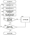
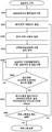
도 6은 도 5의 메인서버의 연산처리부의 기본 동작을 설명하기 위한 흐름도이다.6 is a flowchart for explaining a basic operation of the operation processing unit of the main server of FIG.
신호수신단계로, 메인서버(500)의 연산처리부(550)는 HMD 제어부(150)으로부터, 손움직임 신호를 수신하고(S120), 머리움직임 신호를 수신하고(S130), 실습자의 움직임에 따른 위치 트래킹(모션 트래킹) 영상신호(즉, 실습자 영상신호)를 수신한다(S140). 여기서, 손움직임 신호, 머리움직임 신호, 위치 트래킹 영상신호는 베이스 스테이션부(77)의 적외선신호에 따라 검출된 것으로, 특히, 위치 트래킹 영상신호는 동영상이 아닌, 적외선신호가 검출될 때 카메라부(300)에서 촬상하여 얻어진 영상신호이다.In the signal receiving step, the
시야조정 및 손움직임 표시자 표시단계로, 메인서버(500)의 연산처리부(550)는 머리움직임 신호에 따라 실습자의 시야를 결정하고, 기설정된 가상실습환경의 영상을 출력하되, 상기 실습자의 시야에 따라 조정하여 출력하고, 상기 가상실습환경의 영상에, 손움직임 신호에 따른 위치 또는 위치 트래킹 영상신호에 따른 손 위치에, 손움직임 표시자(70)를 표시한다.The
상호적용 조건 만족여부 판단단계로, 연산처리부(550)는 입력버튼(220)을 통해 수신된 입력버튼 신호가 입력되었는지 여부를 판단하고, 또한, 손움직임 표시자(70)가 가상 방사선 장치(50) 등과 충돌(접촉)되는지 여부를 판단하고(S160), 입력버튼 신호가 입력되지 않았으며, 손움직임 표시자(70)가 가상 방사선 장치(50) 등과 충돌(접촉)하지 않았다면, 종료여부 판단단계(S180)으로 간다.The
상호작용 실행단계로, 상호적용 조건 만족여부 판단단계에서, 입력버튼 신호가 입력되었다면, 연산처리부(550)는 상기 입력버튼 신호에 따른 동작을 수행하고, 상호적용 조건 만족여부 판단단계에서, 손움직임 표시자(70)가 가상 방사선 장치(50) 등과 충돌(접촉)되었다면, 진동출력 제어신호를 생성하여, HMD 제어부(150)으로 전송한다(S170).If the input button signal is input in the step of determining whether the mutual application condition is satisfied, the
종료여부 판단단계로, 종료버튼에 따른 종료신호가 수신되거나, 또는 실습시간 종료에 의해 종료신호가 수신되었다면, 종료하고, 그렇지않다면, 신호수신단계로 되돌아 간다.In the termination end determination step, if the termination signal according to the termination button is received, or if the termination signal is received during the termination of the exercise time, the process is terminated. Otherwise, the process returns to the signal reception step.
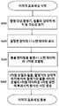
도 7은, 방사선 촬영장치를 이용한 실습모드에서, 도 5의 메인서버의 연산처리부의 동작을 설명하기 위한 흐름도이다.7 is a flowchart for explaining the operation of the arithmetic processing unit of the main server in Fig. 5 in the practice mode using the radiographic apparatus.
가상 실습실 이동단계로, 실습자가 가상 실습실(방사선 촬영실)로 이동함으로써, 메인서버(500)의 연산처리부(550)는, 가상 실습실(방사선 촬영실)을, 가상실습환경의 영상으로 출력하게 한다(S210).The
가상 환자 설정단계로, 연산처리부(550)는 환자선택 대화상자를 디스플레이하게 하며(S220), 실습자(사용자)가 설정한 가상 환자영상을 디스플레이하게 하며(S230), 실습자에 의해 기 설정된 학습과정에 따라, 가상 환자가 촬영 또는 치료를 위한 준비를 하게 한다(S240). 예를들어, 가상환자가 금속 장신구나 촬영에 영향을 미칠 수 있는 교정기나 보철물을 하고 있는지 확인하고, 가상 환자(30)를 가상 방사선 촬영장치(미도시)의 의자에 앉히고, 촬영하려는 촬영법에 따라 가상환자(30)의 머리의 각도를 조절한다.In the virtual patient setting step, the
실습진행단계로, 실습자의 손움직임 표시자의 움직임에 따라, 촬상하기 위한 위치로 이동된 가상 환자의 촬상부위에게 필름을 배치하고, 가상 방사선 촬영 장치의 위치와 각도를 조절하고, 가상 방사선 촬영 장치를 구동시켜 가상 촬영하는 실습을 진행한다(S250).The film is placed on the imaging site of the virtual patient moved to the position for imaging in accordance with the movement of the hand movement indicator of the practitioner to adjust the position and angle of the virtual radiography apparatus, (S250). ≪ / RTI >
즉, 실습자는 카메라(촬영장치)를 가상 환자를 촬상하기 위한 위치로 이동시키고, 촬영에 맞는 필름과 촬영법에 맞는 보조도구 등을 선택하며, 손 움직임 표시자(70)를 이용하여 선택된 필름을 집어 선택된 보조 도구를 사용하여 가상 환자의 촬상부위(예를들어 가상 환자의 입안)에 상기 필름을 위치시킨 후 고정시키고, 가상 방사선 촬영 장치를 촬영부위와 촬영법에 따라 위치와 각도를 조절하고 촬영실 밖으로 나와 가상 방사선 촬영장치의 설정부에서 촬영버튼을 눌러, 방사선 촬영실습을 진행한다.That is, the practitioner moves the camera (photographing apparatus) to a position for capturing a virtual patient, selects a film suitable for photographing and an auxiliary tool suited to the photographing method, picks up the selected film using the
촬영결과 획득여부 판단단계로, 실습진행단계가 끝나서, 실습자가 촬영결과를 확인하기 위해, 손움직임 표시자(70)을 가상 결과화면 모니터(미도시)에 충돌(접촉)시켰는지 여부를 판단하고(S260), 손움직임 표시자(70)을 가상 결과화면 모니터(미도시)에 충돌(접촉)되지 않았다면, 아직 실습이 끝나지 않았으므로, 실습진행단계로 되돌아간다.In the step of judging whether or not the photographing result is obtained, it is determined whether or not the practitioner has collided (contacted) the
가상 실습결과 출력단계로, 촬영결과 획득여부 판단단계에서, 손움직임 표시자(70)가 가상 결과화면 모니터(미도시)에 충돌(접촉)되었다면, 손움직임 표시자(70)에 따라서, 가상환자(30)에게서 제거한 필름을 인상하여, 가상 결과화면 모니터(미도시)에 디스플레이한다(S280).According to the
종료여부 판단단계로, 가상 방사선 장치(50)의 설정부 또는 가상 방사선학 실습 장치의 설정부의 종료버튼(종료 스위치)에 따른 종료신호가 수신되거나, 또는 실습시간 종료에 의해 종료신호가 수신되었다면, 종료하고, 그렇지않다면, 가상 환자 설정단계로 되돌아간다.If the end signal is received in accordance with the setting section of the virtual
도 8은 가상실습환경에서 물건을 잡을 때에 대한, 도 5의 메인서버의 연산처리부의 동작을 설명하기 위한 흐름도이다.Fig. 8 is a flowchart for explaining the operation of the arithmetic processing unit of the main server of Fig. 5 when an object is caught in a virtual laboratory environment.
가동부분과의 충돌여부 판단단계로, 메인서버(500)의 연산처리부(550)는, 실습자(사용자)의 손움직임 표시자(70)가 물체의 가동부분(Actor)(예를들어, 가상 방사선 장치(50)의 소정 가동부분)과 충돌(접촉)하였는지 여부를 판단하고(S310), 만약 손움직임 표시자(70)가 물체의 가동부분(Actor)가 충돌(접촉)하지 않았다면, 종료한다. 여기서, 물체의 가동부분(Actor)은 물체의 움직일 수 있는 부분을 말한다.The
트리거 버튼 신호 수신여부 판단단계로, 가동부분과의 충돌여부 판단단계에서, 손움직임 표시자(70)가 물체의 가동부분(Actor)가 충돌하였다면, HMD 손장착부(핸드 콘트롤러)(200)의 트리거 버튼(217)으로부터 수신된 트리거 버튼 신호(트리거 신호)가 수신되었는지 여부를 연산처리부(550)가 판단하고(S320), 트리거 버튼 신호가 입력되지 않았다면, 실습자가 물체를 잡으려고 한 것이 아니라고 판단하여 종료한다.In the step of determining whether or not the trigger button signal is received, in the step of determining whether or not the trigger button signal is received, if the
손움직임 신호 수신단계로, 트리거 버튼 신호 수신여부 판단단계에서, 트리거 버튼 신호가 수신되었다면, 실습자가 물체를 잡으려고 한 것으로 판단하고, HMD 손장착부(핸드 콘트롤러)(200)의 손 움직임 검출부(210)로부터 손 움직임신호, 즉, 손의 초기 위치 및 각도 값을 수신하여, 메모리부(570)에 저장한다(S330). If the trigger button signal is received in the step of determining whether or not the trigger button signal is received, the hand
트리거 버튼신호 재수신여부 판단단계로, 실습자가 HMD 손장착부(핸드 콘트롤러)(200)의 트리거 버튼을 계속 누름에 의해, 트리거 버튼 신호가 수신되고 있는지 여부를 판단하고(S340), 트리거 버튼 신호 수신되고 있지 않다면, 최종위치로의 움직임단계(S360)로 간다.In step S340, it is determined whether a trigger button signal is being received by the practitioner by continuously depressing the trigger button of the HMD hand-held unit (hand controller) 200. In step S340, If not, the process goes to the step of moving to the final position (S360).
가동부분 이동단계로, 트리거 버튼신호 재수신여부 판단단계에서, 트리거 버튼 신호가 수신되고 있다면, HMD 손장착부(핸드 콘트롤러)(200)의 손 움직임 검출부(210)로부터 현재의 손 움직임신호, 즉, 손의 현재 위치 및 현재 각도 값을 수신하고, 이를 전의 손움직임 신호, 즉, 손의 전 위치 및 전의 각도 값과 비교하여, 가상 물체의 가동부분을 이동 및 회전시킨다(S350).If the trigger button signal is received in the step of determining whether to re-receive the trigger button signal, the hand
최종위치로의 움직임단계로, 가상 물체의 가동부분에 중력이 적용되어 최종 위치로 이동하며, 지면 등에 충돌 시, 물리 엔진에 따른 상호작용 후, 최종위치에서 정지한다(S360).In the movement step to the final position, gravity is applied to the movable part of the virtual object to move to the final position, and after the interaction with the physics engine at the time of collision on the ground or the like, the rotation stops at the final position (S360).
도 9는 도 5의 메인서버의 연산처리부에서, 가상 실습공간에서 텔레포트(실습자의 위치 이동) 처리과정(프로세스)을 나타내는 흐름도이다.9 is a flowchart showing a process (process) of teleport (position shift of a practitioner) in a virtual practice space in the operation processing unit of the main server of Fig.
전후좌우 이동버튼신호 수신여부 판단단계로, 메인서버(500)의 연산처리부(550)는, HMD 손장착부(핸드 콘트롤러)(200)의 전후좌우 이동 버튼(트랙패드)(215)이 눌러짐에 따른, 전후좌우 이동버튼 신호를 수신하였는 지 여부를 판단하고(S510), 전후좌우 이동버튼 신호를 수신하지 않았다면, 종료한다.The
지면 충돌지점 연산단계로, 전후좌우 이동버튼신호 수신여부 판단단계에서, 전후좌우 이동버튼 신호를 수신하였다면, 연산처리부(550)는 HMD 손장착부(핸드 콘트롤러)(200)의 손 움직임 검출부(210)로부터 현재의 손 움직임신호, 즉, 손의 현재 위치 및 현재 각도 값을 수신하고, 현재 위치 및 현재 각도에 따른 현재 방향의 연장선 상에 지면과의 충돌지점을 계산한다(S520).In the ground impact point calculation step, when the forward / backward left / right movement button signal is received in the step of determining whether the front / rear left / right movement button signal is received, the
머리움직임 신호 수신단계로, 연산처리부(550)는, HMD 제어부(150)으로부터 머리움직임 신호, 즉, 머리의 현재 위치 및 현재 각도를 수신하여, 실습자의 머리가 향하고 있는 방향을 결정한다(S530).In the head movement signal reception step, the
충돌지점 중심으로 텔레포트 지점표시단계로, 연산처리부(550)는, 충돌지점 중심으로, 텔레포트 지점을 표시하고, 사용자의 바라보는 방향을 표시한다(S540).In the teleport point display step at the center of the collision point, the
그랩 버튼신호 수신여부 판단단계로, 연산처리부(550)는, HMD 손장착부(핸드 콘트롤러)(200)의 그랩 버튼이 눌려짐에 따른, 그랩 버튼신호를 수신하였는지 여부를 판단하고, 그랩 버튼신호를 수신하였다면, 텔레포트 지점표시 해제단계(S580)으로 간다,In the step of determining whether a grab button signal is received, the
전후좌우 이동버튼신호 재수신여부 판단단계로, 그랩 버튼신호 수신여부 판단단계에서, 그랩 버튼신호를 수신하지 않았다면, 연산처리부(550)는, HMD 손장착부(핸드 콘트롤러)(200)의 전후좌우 이동 버튼(트랙패드)(215)이 눌러짐에 따른, 전후좌우 이동버튼 신호를 다시 수신하였는지 여부를 판단하고(S560), 전후좌우 이동버튼 신호를 다시 수신하지 않았다면, 지면 충돌지점 연산단계로 되돌아간다.The
위치 이동실행 단계로, 연산처리부(550)는, 충돌지점 중심으로 텔레포트 지점표시단계에서 표시한, 사용자의 바라보는 방향과 텔레포트 지점으로 실습자(사용자)의 방향과 위치 이동을 행한 영상을 생성하여 HMD 제어부(150)으로 전송한다(S570).In the position movement execution step, the
텔레포트 지점표시 해제단계로, 충돌지점 중심으로 텔레포트 지점표시단계에서 표시한 텔레포트 지점을 해제한다(S580).In the teleport point display canceling step, the teleport point displayed in the teleport point display step is canceled at the collision point center (S580).
도 10은 본 발명의 가상 방사선학 실습 장치를 이용한 가상 실습시, 방사선 촬영 결과화면의 연산과정의 일예를 설명하는 흐름도이다.10 is a flowchart for explaining an example of a calculation process of a radiographing result screen in a virtual practice using a virtual radiograph exercise apparatus according to the present invention.
도 10에서는 CT스캔 데이터를 통한 결과화면을 생성하는 과정을 설명한다.FIG. 10 illustrates a process of generating a result screen through CT scan data.
촬영대상와 촬영기와 필름의 상대적 위치 읽기단계로, 메인서버(500)의 연산처리부(550)는, 촬영대상, 촬영기, 필름의 상대적 위치 및 각도 값을 읽어들인다(S610).In operation S610, the
CT 스캔 데이터 로드단계로, 연산처리부(550)는 설정된 환자의 CT 스캔 데이터를 데이터베이스(560)로부터 읽어들인다(S620).In the CT scan data loading step, the
CT 스캔데이터의 3차원 모델링단계로, 연산처리부(550)는 볼륨렌더링을 통한 CT 스캔데이터의 3차원 모델링을 행한다(S630)In the three-dimensional modeling step of the CT scan data, the
방사선 사진 생성단계로, 3차원 모델과 필름, 촬영기의 상대적 위치에 따라, 촬영기와 필름 사이의 모델의 3차원 데이터를 2차원 평면에 투과시켜 방사선 사진을 생성한다(S650).In step S650, the three-dimensional data of the model between the photographing machine and the film is transmitted to the two-dimensional plane according to the relative positions of the three-dimensional model, the film, and the photographing machine.
기본적으로 일반 3D 그래픽 경우 메쉬와 텍스쳐로 구성되어 있으며, 여기서, 메쉬는 외형을 결정하는 것으로 내부가 비어 있는 외형의 경계선만을 표시한 데이터이다. 일반적으로 이 메쉬 위에 텍스쳐(즉, 그림파일)를 그려넣어 3D 그래픽이 표현된다. Basically, in the case of general 3D graphics, the mesh is composed of a mesh and a texture. Here, the mesh is data in which only the outline of the outline of the inside is determined by determining the outline. In general, a 3D graphic is rendered by drawing a texture (ie, a picture file) on the mesh.
이러한 방식과 달리 볼륨렌더링의 경우, 매우 얇은 층의 평면텍스쳐를 층층이 쌓아 올린 것과 같다. 실제로 2차원 명면이 쌓여 3차원 입체가 되는 것과 동일한 방식으로 물체의 내부에 대한 정보다 있다는 것이 장점이다. 그러나 연산량이 많아 시스템 로드가 많이 걸리는 것이 단점이다.Unlike this approach, for volume rendering, it is like layering a very thin layer of planar texture. In fact, it is an advantage that the information about the inside of the object is the same way that the two-dimensional surface is piled up and becomes three-dimensional solid. However, the drawback is that the system load is high because of the large amount of computation.
본 발명에서는 CT 스캔 데이터에서 스캔 간격에 따라 평면 텍스쳐를 쌓아올린 후 그 사이 공간을 인터폴레이션(interpolation) 을 통해 채워 넣어 내부의 정보를 모두 담고 있는 3D모델을 만든다. In the present invention, a plane texture is piled up according to a scan interval in CT scan data, and a space is interpolated through interpolation to create a 3D model containing all the information inside.
도 11은 본 발명의 가상 방사선학 실습 장치를 이용한 가상 실습시, 방사선 촬영 결과화면의 연산과정의 다른 일예를 설명하는 흐름도이다.11 is a flowchart for explaining another example of the calculation process of the radiographing result screen in the virtual practice using the virtual radiograph exercise apparatus of the present invention.
도 11에서는 기존 방사선 사진을 통한 결과화면을 생성하는 과정을 설명한다.FIG. 11 illustrates a process of generating a result screen based on an existing radiograph.
촬영대상와 촬영기와 필름의 상대적 위치 읽기단계로, 메인서버(500)의 연산처리부(550)는, 촬영대상, 촬영기, 필름의 상대적 위치 및 각도 값(즉, 촬영 대상의 기존 보유한 방사선 사진과의 상대 값)을 읽어들인다(S710).The
방사선사진 로드단계로, 연산처리부(550)는 설정된 환자의 타겟부위 방사선 사진을 데이터베이스(560)로부터 읽어들인다(S720).In the radiographic loading step, the
원본 방사선 사진의 크기 조절단계로, 연산처리부(550)는, 방사선사진 로드단계에 읽어들인 타겟부위 방사선 사진인, 원본 방사선 사진을 투영하여, 촬영기 평행방향으로 이동하고, 투영에 따른 사진 크기를 확대 또는 축소한다(S730).In the size adjustment step of the original radiograph, the
접점존재 여부판단단계로, 원본 방사선 사진의 크기 조절단계 후, 투영사진과 필름이, 접점이 있는 지 여부를 판단하고(S750), 접점이 없다면, 원본 방사선 사진의 크기 조절단계로 되돌아간다.In step S750, it is determined whether or not there is a contact between the projection photograph and the film after the size adjustment step of the original radiograph. If there is no contact point, the process returns to the size adjustment step of the original radiograph.
픽셀값 저장단계로, 접점존재 여부판단단계에서 접점이 있다면, 상기 접점의 투영사진 픽셀값을 결과사진을 저장하는 버퍼에 복사한다(S760).In the pixel value storing step, if there is a contact point in the step of determining whether a contact exists, the projected pixel value of the contact point is copied to a buffer for storing the result picture in step S760.
필름영역을 벗어났는지 여부 판단단계로, 투영사진이 필름영역을 벗어났는지 여부를 판단하고, 벗어나지 않았다면, 원본 방사선 사진의 크기 조절단계로 되돌아가고, 투영사진이 필름영역을 벗어 났다면, 종료한다(S770).Determining whether the projected picture is out of the film area, and if not, returning to the step of adjusting the size of the original radiograph and terminating if the projected picture is out of the film area (step < RTI ID = 0.0 > S770).
도 11에서는, CT 스캔 데이터는 없으나 특정부위에 대한 방사선 사진이 있는 경우 사용하며, 원본사진이 있는 부위를 중심으로 같은 방향이지만 각도 등 촬영 미숙에 따른 잘못된 (상의 연장 등) 결과 방사선 사진을 생성한다.In FIG. 11, CT scan data is not used, but it is used when there is a radiograph for a specific region, and a radiograph is generated as a result of erroneous .
이상과 같이, 본 발명은, 기존 방사선학 실습에서 실제 방사선 촬영장비와 마네킹을 이용하여 촬영하던 방식을 가상현실 속에서 가상의 촬영장비와 다양한 가상의 환자를 통하여 실습을 실시하도록 하여 기존 방사선학 실습 방식이 가지고 있던 문제점들인 방사선에 직접적인 노출, 실습실 운영에 들어가는 높은 비용, 제한적인 실습 경험을 해결할 수 있다.As described above, in the present invention, in the conventional radiology practice, the method of shooting using the actual radiographic equipment and the mannequin is practiced in the virtual reality through the virtual imaging equipment and various virtual patients, Direct exposure to radiation problems, high cost of running the lab, and limited practical experience can be solved.
본 발명은 HMD(Head Mounted Display) 머리장착부(100)를 이용하여 사용자가 시각과 청각을 통하여 경험하는 가상현실 속에서, HMD 손장착부(hand motion controller)(200)를 이용하여 가상의 방사선 촬영 장비를 조작하여 방사선 촬영 실습을 실시하고 가상의 촬영대상, 장비의 위치, 설정에 따라 촬영결과를 시뮬레이션 하여 가상현실 속에 결과를 출력하는 가상현실 기반 방사선학 실습 장치 및 방법에 관한 것이다.The present invention relates to a virtual radiological imaging apparatus using an HMD hand motion controller (200) in a virtual reality in which a user experiences visual and auditory experience using an HMD (Head Mounted Display) And a virtual reality-based radiological training apparatus and method for outputting a result in a virtual reality by simulating a radiographic result according to a virtual object to be imaged, an apparatus position, and a setting.
본 발명은 하드웨어와 소프트웨어 부분을 구비하며, 하드웨어부분은 시청각적 가상현실을 사용자에게 경험하게 해주는 HMD 머리장착부(100), 사용자의 손의 위치와 각도를 추적하게 해주고 입력장치를 통해 입력신호를 받는 HMD 손장착부(hand motion controller)(200)와 가상현실을 시뮬레이션 하는 컴퓨터인 메인서버(500)를 포함하여 이루어지며, 소프트웨어부분의 경우 윈도우 운영체제 기반 단일 어플리케이션으로 이루어질 수 있다. The present invention includes a hardware and software portion, which includes an HMD head mount (100) that allows the user to experience an audiovisual virtual reality, a user interface that tracks the position and angle of the user's hand and receives input signals through the input device An HMD
즉, 본 발명은 가상현실 속에서 방사선학 실습을 실시하는 장치 및 방법에 관한 것으로, HMD와 가상현실을 렌더 하는 소프트웨어를 통해 가상현실을 경험하게 해주며, 가상현실 속에 있는 방사선 촬영장비를 HMD 손장착부(hand motion controller)(200)로 조작할 수 있는 방법을 제공하고, 가상의 촬영장비와 환자 촬영 설정 등을 모두 반영하여 엑스레이 촬영 시뮬레이션을 실시하고, 결과 엑스레이 이미지를 가상현실 속에 출력해줌으로써 가상현실 속에서 방사선학 실습을 실시할 수 있다.That is, the present invention relates to an apparatus and method for performing radiological exercises in a virtual reality, which allows a user to experience virtual reality through HMD and software for rendering a virtual reality, (hand motion controller) 200, performs an X-ray imaging simulation by reflecting both a virtual imaging device and a patient imaging setting, and outputs a resultant X-ray image to a virtual reality You can conduct radiology exercises.
이상과 같이 본 발명은 비록 한정된 실시예와 도면에 의해 설명되었으나, 본 발명은 상기의 실시예에 한정되는 것은 아니며, 이는 본 발명이 속하는 분야에서 통상의 지식을 가진 자라면 이러한 기재로부터 다양한 수정 및 변형이 가능하다. 따라서, 본 발명 사상은 아래에 기재된 특허청구범위에 의해서만 파악되어야 하고, 이의 균등 또는 등가적 변형 모두는 본 발명 사상의 범주에 속한다고 할 것이다.While the present invention has been particularly shown and described with reference to exemplary embodiments thereof, it is to be understood that the invention is not limited to the disclosed exemplary embodiments, but, on the contrary, Modification is possible. Accordingly, the spirit of the present invention should be understood only in accordance with the following claims, and all equivalents or equivalent variations thereof are included in the scope of the present invention.
10 : 가상 방사선학 실습 장치 20 : 실습자
30 : 가상 환자 50 : 가상 방사선 장치
70 : 손 움직임 표시자 76 : HMD 세트
77 : 베이스 스테이션부 100 : HMD 머리장착부
110 : 머리움직임 검출부 120 : HMD 영상출력부
130 : 이어폰 150 : HMD제어부
160 : 머리 움직임 신호 전처리부 170 : 영상출력 제어부
177 : 음향출력 제어부 200 : HMD 손장착부
210 : 손움직임 검출부 215 : 전후좌우 이동 버튼
217 : 트리거 버튼 220 : 입력버튼
230 : 진동발생부 237: 전원 온/오프 버튼
235 : 메뉴버튼 250 : 제1 데이터송수신부
260 : 손 움직임 신호 전처리부 270 : 입력버튼신호 전처리부
280 : 진동출력 제어부 300 : 카메라부
310 : 영상신호 전처리부 350 : HMD 제어부의 연산처리부
370 : 제2 데이터송수신부 500 : 메인서버
510 : 데이터 송수신부 550 : 메인서버의 연산처리부
560 : 데이터베이스 570 : 메모리부
575 : 스피커부 600 : 디스플레이부10: Virtual radiology practice device 20: Practitioner
30: virtual patient 50: virtual radiation device
70: hand movement indicator 76: HMD set
77: base station unit 100: HMD head mount
110: head motion detection unit 120: HMD video output unit
130: earphone 150: HMD controller
160: Head movement signal preprocessing unit 170: Video output control unit
177: Acoustic output control unit 200: HMD hand mount
210: hand motion detection unit 215: forward / backward / leftward movement button
217: Trigger button 220: Input button
230: Vibration generator 237: Power on / off button
235: Menu button 250: First data transmission /
260: hand motion signal preprocessing unit 270: input button signal preprocessing unit
280: Vibration output control unit 300:
310: video signal preprocessing unit 350: operation processing unit of HMD control unit
370: second data transmission / reception unit 500: main server
510: Data transmission / reception unit 550: Operation processing unit of main server
560: Database 570: Memory part
575: speaker section 600: display section
Claims (23)
실습자의 손에 장착되며, 영상 상에 가상 방사선 장치를 조작하기 위해, 실습자의 손이 움직일때, 실습자의 손 움직임신호를 검출하는 손 움직임 검출부를 포함하는, HMD 손장착부;
HMD 손장착부로부터 손 움직임신호를 수신하여 메인서버로 전송하고, 메인서버로 부터 수신된 영상을 HMD 머리장착부로 전송하는, HMD 제어부;
HMD 제어부로부터 수신한 손 움직임신호를 수신하고, 손 움직임 신호에 따라서, 영상상에서, 실습자의 가상의 손인, 손 움직임 표시자가 움직이며, 움직여진 손 움직임 표시자를 포함하는 영상을, HMD 제어부로 전송하는 메인서버;
를 포함하여 이루어진 것을 특징으로 하는, 가상 방사선학 실습 장치.An HMD head attaching part mounted on a head of a practitioner and outputting an image including a virtual radiological device for practicing a virtual radiography to an HMD (Head Mounted Display) video output part;
An HMD hand mount mounted on the hands of the practitioner and including a hand motion detection section for detecting a hand motion signal of the practitioner when the hands of the practitioner are moved to manipulate the virtual radiation apparatus on the image;
An HMD controller for receiving a hand motion signal from the HMD hand mount and transmitting the hand motion signal to the main server and transmitting the image received from the main server to the HMD head mount;
A virtual hand of a practitioner, a hand motion indicator moves on the image, and an image including the moved hand motion indicator is transmitted to the HMD controller in response to the hand motion signal received from the HMD controller Main server;
Wherein the virtual radiographing device comprises:
HMD 머리장착부는, 메인서버로부터 HMD 제어부를 통해 수신되는 음향신호를 출력하는 이어폰;
을 더 포함하여 이루어진 것을 특징으로 하는, 가상 방사선학 실습 장치.The method according to claim 1,
The HMD head mount includes an earphone for outputting a sound signal received from the main server through the HMD controller;
Further comprising a virtual radiographing unit for radiographing the virtual radiograph.
영상에서, 손 움직임 표시자와 충돌된 가상의 물체가, 상기 영상 상에서 손 움직임 표시자로 잡고 있음을 나타내게 하는, 트리거 버튼;
을 더 포함하여 이루어진 것을 특징으로 하는, 가상 방사선학 실습 장치.3. The HMD hand mount according to claim 2,
A trigger button for indicating, in the image, that a virtual object colliding with the hand movement indicator is displayed as a hand movement indicator on the image;
Further comprising a virtual radiographing unit for radiographing the virtual radiograph.
손 움직임 표시자와 충돌된 가상의 물체의 부분이 가동부분인 경우에, 메인서버는, 트리거 버튼으로부터 HMD 제어부를 통해 수신된 트리거 버튼 신호가 수신되면, 영상 상에서, 가상의 물체의 가동부분이, 손 움직임 표시자의 움직임에 따라, 움직이도록 이루어진 것을 특징으로 하는, 가상 방사선학 실습 장치.The method of claim 3,
When the portion of the virtual object colliding with the hand movement indicator is the movable portion, when the trigger button signal received from the trigger button via the HMD control portion is received, the movable portion of the virtual object, And the movement of the hand movement indicator is made to move in accordance with the movement of the hand movement indicator.
영상상에서 손 움직임 표시자와 가상의 물체가 충돌될 때, 진동을 출력하는 진동발생부;
를 더 포함하고 있는 것을 특징으로 하는, 가상 방사선학 실습 장치.5. The HMD hand mount of claim 4,
A vibration generator for outputting a vibration when a hand movement indicator and a virtual object collide with each other on the image;
Further comprising a virtual radiographing device for radiographing the virtual radiograph.
실습자의 머리 움직임을 검출하는 머리 움직임 검출부;
를 더 포함하고 있는 것을 특징으로 하는, 가상 방사선학 실습 장치.6. The system of claim 5, wherein the HMD head mount
A head movement detecting unit for detecting a head movement of a practitioner;
Further comprising a virtual radiographing device for radiographing the virtual radiograph.
메인서버는 머리 움직임 검출부로부터 HMD 제어부를 통해 머리움직임 신호를 수신하고, 머리움직임 신호에 따라, 영상의 시점을 변경한 영상을 생성하여, HMD 제어부로 전송하는 것을 특징으로 하는, 가상 방사선학 실습 장치.The method according to claim 6,
Wherein the main server receives the head motion signal from the head motion detection unit through the HMD control unit and generates an image in which the viewpoint of the image is changed according to the head motion signal and transmits the generated image to the HMD control unit.
실습자를 촬영하여 위치 트래킹 영상을 생성하는 카메라부;를 더 포함하는 것을 특징으로 하는, 가상 방사선학 실습 장치.8. The method of claim 7,
And a camera unit for photographing a practitioner to generate a position tracking image.
메인서버는 카메라부로부터 HMD 제어부를 통해 수신한 위치 트래킹 영상, 머리움직임 신호, 손 움직임 신호에 따라, 영상을 생성하여 HMD 제어부로 전송하는 것을 특징으로 하는, 가상 방사선학 실습 장치.9. The method of claim 8,
Wherein the main server generates an image according to a position tracking image, a head motion signal, and a hand motion signal received from the camera unit via the HMD controller, and transmits the generated image to the HMD controller.
HMD 손장착부는, 전후좌우 이동 버튼(트랙패드)를 더 포함하며,
메인서버는, 전후좌우 이동 버튼으로부터 출력된 전후좌우 이동 버튼 신호가, HMD 제어부를 통해 수신되면, 영상 상에서, 머리움직임 신호에 의한 방향으로, 실습자가 이동함에 따라, 실습자에게 보이는 영상을 생성하여, HMD 제어부로 전송하는 것을 특징으로 하는, 가상 방사선학 실습 장치.9. The method of claim 8,
The HMD hand mount further includes a front, rear, left and right movement button (track pad)
When the forward / backward left / right movement button signal outputted from the forward / backward left / right movement button is received through the HMD control unit, the main server generates an image to be seen by the practitioner as the practitioner moves in the direction of the head movement signal on the image To the HMD control unit.
머리움직임 신호, 위치 트래킹 영상, 손움직임 신호는, 베이스 스테이션부의 적외선 발생에 동기되어 검출된 신호인 것을 특징으로 하는, 가상 방사선학 실습 장치.11. The method of claim 10,
Wherein the head movement signal, the position tracking image, and the hand movement signal are signals detected in synchronization with the infrared ray generation of the base station unit.
실습자가, 가상 방사선 장치 또는 가상 환자를 설정하도록하는 설정부를 더 포함하는 것을 특징으로 하는, 가상 방사선학 실습 장치.12. The method according to any one of claims 1 to 11,
Further comprising a setting unit for allowing the practitioner to set a virtual radiological apparatus or a virtual patient.
실습자의 손에 장착된 HMD 손장착부의 손 움직임 검출부는, 영상 상에 가상 방사선 장치를 조작하기 위해, 실습자의 손이 움직일때, 실습자의 손 움직임신호를 검출하여, HMD 제어부를 통해 메인서버의 연산처리부로 전송하고,
메인서버의 연산처리부는 수신된 손 움직임 신호에 따라서, 영상 상에서, 실습자의 가상의 손인, 손 움직임 표시자가 움직이며, 움직여진 손 움직임 표시자를 포함하는 영상을, HMD 제어부를 통해 HMD 머리장착부의 HMD 영상출력부로 출력하는 것을 특징으로 하는, 가상 방사선학 실습 장치의 구동방법.An HMD image output unit of an HMD (Head Mounted Display) head mounted on the head of a practitioner outputs an image including a virtual radiological apparatus for virtual radiography practice,
The hand motion detection section of the HMD hand mount section mounted on the hands of the practitioner detects a hand motion signal of the practitioner when the hands of the practitioner move to operate the virtual radiography apparatus on the image, To the processing unit,
The arithmetic processing unit of the main server moves an image of the virtual hand of the practitioner moving the hand motion marker on the image and including the moved hand motion indicator on the image through the HMD control unit to the HMD And outputs it to the video output unit.
메인서버의 연산처리부는 머리움직임 신호에 따라 실습자의 시야를 결정하고, 기설정된 가상실습환경의 영상을 출력하되, 실습자의 시야에 따라 조정하여 출력하고, 가상실습환경의 영상에, 손움직임 신호에 따른 위치 또는 위치 트래킹 영상신호에 따른 손 위치에, 실습자의 가상의 손인, 손움직임 표시자를 표시하는, 시야조정 및 손움직임 표시자 표시단계;
메인서버의 연산처리부는, HMD 손장착부의 입력버튼이 선택됨에 따른 입력버튼 신호가 수신되었는지 여부를 판단하고, 손움직임 표시자가 가상 방사선 장치와 충돌되었는지 여부를 판단하는, 상호적용 조건 만족여부 판단단계;
메인서버의 연산처리부는, 상호적용 조건 만족여부 판단단계에서, 입력버튼 신호가 입력되었다면, 입력버튼 신호에 따른 동작을 수행하고, 상호적용 조건 만족여부 판단단계에서, 손움직임 표시자가 가상 방사선 장치와 충돌되었다면, 진동출력 제어신호를 생성하여, HMD 제어부로 전송하는, 상호작용 실행단계;
를 포함하여 이루어진 것을 특징으로 하는, 가상 방사선학 실습 장치의 구동방법.The operation processing unit of the main server includes a head movement signal detected from the head movement detection unit mounted on the HMD head mounting unit, a hand movement signal detected from the hand movement detection unit of the HMD hand mount, and a position tracking image Via an HMD control unit;
The arithmetic processing unit of the main server determines the field of view of the practitioner according to the head movement signal, outputs the image of the virtual practice environment preset, adjusts according to the field of view of the practitioner and outputs the adjusted image, Displaying a virtual hand and a hand motion indicator of a practitioner at a hand position according to a position or position tracking video signal according to the position and / or position tracking video signal;
The operation processing unit of the main server determines whether or not the input button signal corresponding to the selection of the input button of the HMD hand mount unit is received and determines whether or not the hand motion indicator has collided with the virtual radiological apparatus, ;
The operation processing unit of the main server performs an operation according to the input button signal if the input button signal is input in the step of determining whether or not the mutual application condition is satisfied, Generating an oscillation output control signal if it is collided, and transmitting the oscillation output control signal to the HMD control section;
And driving the virtual radiological apparatus.
실습진행단계 후, 손움직임 표시가 가상 결과화면 모니터와 충돌되었다면, 메인서버의 연산처리부는, 손움직임 표시자에 따라서, 가상환자에게서 제거한 필름을 가상 인상하여, 가상 결과화면 모니터에 디스플레이하는, 가상 실습결과 출력단계;
를 포함하여 이루어진 것을 특징으로 하는, 가상 방사선학 실습 장치의 구동방법.According to the motion of the hand movement indicator moving in accordance with the hand motion signal of the practitioner, the arithmetic processing unit of the main server places a virtual film on the imaging site of the virtual patient moved to the position for imaging on the image, Adjusting a position and an angle of the virtual camera and driving the virtual radiographic apparatus to conduct virtual radiographing;
If the hand movement display has collided with the virtual result screen monitor after the exercise progress step, the arithmetic processing unit of the main server displays a virtual screen monitor on the virtual result screen monitor in accordance with the hand movement indicator, Output step of practice result;
And driving the virtual radiological apparatus.
실습진행단계 전에,
영상상에서, 실습자가 가상 방사선 촬영실로 이동함으로써, 메인서버의 연산처리부는, 가상 방사선 촬영실의 영상을 HMD 제어부를 통해 HMD 영상출력부로 전송하는, 가상 실습실 이동단계;
가상 실습실 이동단계 후, 메인서버의 연산처리부는, 환자선택 대화상자를 디스플레이하게 하고, 실습자가 설정한 가상 환자영상을, HMD 제어부를 통해 HMD 영상출력부로 전송하는, 가상 환자 설정단계;
를 더 포함하여 이루어진 것을 특징으로 하는, 가상 방사선학 실습 장치의 구동방법.16. The method of claim 15,
Before the exercise phase,
The operation processor of the main server transfers the image of the virtual radiography room to the HMD image output unit through the HMD control unit by moving the practitioner to the virtual radiography room on the image;
A virtual patient setting step of causing the operation processing unit of the main server to display a patient selection dialog box and transmitting the virtual patient image set by the practitioner to the HMD image output unit through the HMD control unit;
Further comprising the steps of: (a) providing a virtual radiographing device;
메인서버의 연산처리부는, HMD 손장착부의 트리거 버튼으로부터 HMD 제어부를 통해 트리거 버튼 신호가 수신되었다면, HMD 손장착부의 손 움직임 검출부로부터 현재의 손 움직임신호를 수신하고, 전의 손움직임 신호와 비교하여, 가상 물체의 가동부분을 이동시키는, 가동부분 이동단계
를 포함하여 이루어진 것을 특징으로 하는, 가상 방사선학 실습 장치의 구동방법.The arithmetic processing unit of the main server may be configured such that if the hand motion indicator collides with the movable part of the virtual object on the image and the trigger button signal is received from the trigger button of the HMD hand mount unit through the HMD control unit, Receiving a hand motion signal from the hand motion detection unit of the HMD hand mount unit and storing the hand motion signal in the memory unit;
The operation processing unit of the main server receives the current hand motion signal from the hand motion detection unit of the HMD hand mount unit and compares it with the previous hand motion signal if a trigger button signal is received from the trigger button of the HMD hand mount unit via the HMD control unit, Moving part moving step of moving the movable part of the virtual object
And driving the virtual radiological apparatus.
메인서버의 연산처리부는, 전후좌우 이동버튼 신호를 수신하였다면, HMD 손장착부의 손 움직임 검출부로부터의 손의 위치 및 각도값으로 이루어진 손 움직임신호를 수신하고, 손 움직임신호의 위치 및 각도에 따른 방향의 연장선 상에 지면과의 충돌지점을 계산하는, 지면 충돌지점 연산단계;
메인서버의 연산처리부는, HMD 제어부으로부터 머리의 위치 및 각도로 이루어진 머리움직임 신호를 수신하여, 실습자의 머리가 향하고 있는 방향을 결정하는, 머리움직임 신호 수신단계;
메인서버의 연산처리부는, 충돌지점 중심으로, 텔레포트 지점을 표시하고, 사용자의 바라보는 방향을 표시하는, 충돌지점 중심으로 텔레포트 지점표시단계;
를 포함하여 이루어진 것을 특징으로 하는, 가상 방사선학 실습 장치의 구동방법.The operation processing unit of the main server may include a step of determining whether a forward, backward, leftward, and rightward movement button signals are received from the front, rear, left, and right movement buttons (track pads) of the HMD hand mount unit through the HMD control unit;
When receiving the forward, backward, leftward, and rightward movement button signals, the main processor of the main server receives a hand motion signal composed of hand position and angle values from the hand motion detection unit of the HMD hand mount, Calculating a point of collision with the ground on an extension line of the ground;
The arithmetic processing unit of the main server receives the head motion signal composed of the position and angle of the head from the HMD control unit and determines a direction in which the head of the practitioner is heading;
The operation processing unit of the main server displays a teleport point at the center of the collision point and displays a teleport point at the center of the collision point,
And driving the virtual radiological apparatus.
충돌지점 중심으로 텔레포트 지점표시단계 후, 메인서버의 연산처리부는, HMD 손장착부의 그랩 버튼으로부터의 그랩 버튼신호를 수신하였는지 여부를 판단는, 그랩 버튼신호 수신여부 판단단계;
그랩 버튼신호 수신여부 판단단계에서, 그랩 버튼신호를 수신하지 않았다면, 메인서버의 연산처리부는, HMD 손장착의 전후좌우 이동 버튼으로부터의 전후좌우 이동버튼 신호를 수신하였는지 여부를 판단하고, 전후좌우 이동버튼 신호를 다시 수신하지 않았다면, 지면 충돌지점 연산단계로 되돌아가는, 전후좌우 이동버튼신호 재수신여부 판단단계;
메인서버의 연산처리부는, 충돌지점 중심으로 텔레포트 지점표시단계에서 표시한, 사용자의 바라보는 방향과 텔레포트 지점으로 실습자의 방향과 위치 이동을 행한 영상을 생성하여 HMD 제어부으로 전송하는, 위치 이동실행 단계;
위치 이동실행 단계 후, 또는, 그랩 버튼신호 수신여부 판단단계에서, 그랩 버튼신호를 수신하였다면, 메인서버의 연산처리부는, 충돌지점 중심으로 텔레포트 지점표시단계에서 표시한 텔레포트 지점을 해제하는, 텔레포트 지점표시 해제단계;
를 더 포함하여 이루어진 것을 특징으로 하는, 가상 방사선학 실습 장치의 구동방법.19. The method of claim 18,
After the teleport point display step with the center of the collision point, the arithmetic processing unit of the main server determines whether or not a grab button signal has been received to determine whether or not the grab button signal from the grab button of the HMD hand mount unit has been received;
If the grab button signal has not been received, the arithmetic processing unit of the main server determines whether or not the forward, backward, leftward, and rightward movement button signals from the forward, backward, leftward, and rightward movement buttons of the HMD hand mount have been received, Determining whether the forward, backward, leftward, and rightward movement button signals are re-received, returning to the ground impact point calculation step if the button signal is not received again;
The operation processing unit of the main server generates an image in which the direction and position of the practitioner are moved from the viewing direction of the user and the teleport point and displayed at the teleport point display step at the center of the collision point to transmit the image to the HMD control unit ;
After receiving the grab button signal in the step of determining whether or not to receive the grab button signal, the arithmetic processing unit of the main server transmits the teleport point to the teleport point A display releasing step;
Further comprising the steps of: (a) providing a virtual radiographing device;
메인서버의 연산처리부는, MRI 스캔 데이터 또는 CT 스캔 데이터로 이루어진 의료영상 데이터를 영상처리서버로 전송하는 단계;
영상처리서버는, 심층인공신경망구조를 사용하여, 메인서버로부터 수신한 의료영상 데이터의 영상분할을 행하고, 분할된 영상을 이용하여 장기 또는 조직의 메쉬 데이터(표면정보)를 산출하고, 산출된 장기 또는 조직의 표면정보(메쉬 데이터)를 메인서버로 전송하는 단계;
메인서버는 수신된 표면정보(메쉬 데이터)를 가상환자의 소정부분을, 3D모델의 표면정보(메쉬 데이터)로 변경하여, 가상환자를 디스플레이하는 단계;
를 포함하는 것을 특징으로 하는 가상 방사선학 실습 장치의 구동방법.A method of driving a virtual radiology training apparatus in which a main server generates and displays a virtual patient before performing a virtual training,
The operation processing unit of the main server includes: transmitting medical image data including MRI scan data or CT scan data to an image processing server;
The image processing server performs image segmentation of the medical image data received from the main server using the in-depth artificial neural network structure, calculates mesh data (surface information) of the organ or tissue using the divided images, Or the surface information of the organization (mesh data) to the main server;
The main server changes the received surface information (mesh data) to a surface part information (mesh data) of the 3D model to display a virtual patient;
And driving the virtual radiological apparatus.
메인서버의 연산처리부는, 촬영대상, 촬영기, 필름의 상대적 위치 및 각도 값을 읽어들이는, 촬영대상과 촬영기와 필름의 상대적 위치 읽기단계;
메인서버의 연산처리부는 설정된 환자의 CT 스캔 데이터를 데이터베이스로부터 읽어들이는, CT 스캔 데이터 로드단계;
메인서버의 연산처리부는 볼륨렌더링을 통한 CT 스캔데이터의 3차원 모델링을 행하는, CT 스캔데이터의 3차원 모델링단계;
메인서버의 연산처리부는 CT 스캔데이터의 3차원 모델링단계에서 생성된 3차원 모델과, 필름 및 촬영기의 상대적 위치에 따라, 촬영기와 필름 사이의 상기 3차원 모델의 3차원 데이터를 2차원 평면에 투과시켜 방사선 사진을 생성하는, 방사선 사진 생성단계;
를 포함하여 이루어진 것을 특징으로 하는, 가상 방사선학 실습 장치의 구동방법.A method of driving a virtual radiological training apparatus in which a main server generates a virtual radiography result screen after a virtual training session is completed,
The arithmetic processing unit of the main server reads the relative positions of the object to be imaged, the imager and the film, and the relative position of the object to be imaged, the imager and the film;
The operation processing unit of the main server includes a CT scan data loading step of reading the CT scan data of the set patient from the database;
The operation processing unit of the main server may be a three-dimensional modeling step of CT scan data for performing three-dimensional modeling of CT scan data through volume rendering;
The operation processing unit of the main server transmits the three-dimensional data of the three-dimensional model between the camera and the film to the two-dimensional plane according to the three-dimensional model generated in the three-dimensional modeling step of the CT scan data and the relative positions of the film and the camera. Thereby generating a radiographic image;
And driving the virtual radiological apparatus.
메인서버의 연산처리부는, 촬영대상, 촬영기, 필름의 상대적 위치 및 각도 값을 읽어들이는, 촬영대상과 촬영기와 필름의 상대적 위치 읽기단계;
메인서버의 연산처리부는, 기 설정된 환자의 타겟부위 방사선 사진을 데이터베이스로부터 읽어들이는, 방사선사진 로드단계;
메인서버의 연산처리부는, 방사선사진 로드단계에 읽어들인 타겟부위 방사선 사진인, 원본 방사선 사진을 투영하여, 촬영기 평행방향으로 이동하고, 투영에 따른 사진 크기를 확대 또는 축소하는, 원본 방사선 사진의 크기 조절단계;
메인서버의 연산처리부는, 원본 방사선 사진의 크기 조절단계 후, 투영사진과 필름이, 접점이 있는지 여부를 판단하고, 접점이 없다면, 원본 방사선 사진의 크기 조절단계로 되돌아가는, 접점존재 여부판단단계;
접점존재 여부판단단계에서 접점이 있다면, 메인서버의 연산처리부는, 상기 접점의 투영사진 픽셀값을, 결과사진을 저장하는 버퍼에, 복사하는, 픽셀값 저장단계;
를 포함하여 이루어진 것을 특징으로 하는, 가상 방사선학 실습 장치의 구동방법.A method of driving a virtual radiological training apparatus in which a main server generates a virtual radiography result screen after a virtual training session is completed,
The arithmetic processing unit of the main server reads the relative positions of the object to be imaged, the imager and the film, and the relative position of the object to be imaged, the imager and the film;
The arithmetic processing unit of the main server includes: a radiographic photographing step of reading a target region radiograph of a predetermined patient from a database;
The operation processing unit of the main server may be configured to project the original radiographic image, which is the target region radiographic image read in the radiographic image loading step, in the parallel direction of the image capturing apparatus, to enlarge or reduce the size of the image according to the projection, An adjusting step;
The arithmetic processing unit of the main server determines whether or not there is a contact between the projection photograph and the film after the size adjustment step of the original radiograph and returns to the size adjustment step of the original radiograph if there is no contact, ;
If there is a contact point in the contact presence determination step, the operation processing unit of the main server copies the projected picture pixel value of the contact point into a buffer for storing the result picture, the pixel value storage step;
And driving the virtual radiological apparatus.
투영사진이 필름영역을 벗어났는지 여부를 판단하고, 벗어나지 않았다면, 원본 방사선 사진의 크기 조절단계로 되돌아가고, 투영사진이 필름영역을 벗어 났다면, 종료하는, 필름영역을 벗어났는지 여부 판단단계;
를 더 포함하여 이루어진 것을 특징으로 하는, 가상 방사선학 실습 장치의 구동방법.23. The method of claim 22,
Determining whether the projected picture is out of the film area, determining whether the projected picture is out of the film area, returning to the size adjustment step of the original radiograph, if not, and ending if the projected picture is out of the film area;
Further comprising the steps of: (a) providing a virtual radiographing device;
Priority Applications (1)
| Application Number | Priority Date | Filing Date | Title |
|---|---|---|---|
| KR1020210065235A KR20210064129A (en) | 2017-02-24 | 2021-05-21 | Virtual reality-based radiology practice apparatus and method |
Applications Claiming Priority (2)
| Application Number | Priority Date | Filing Date | Title |
|---|---|---|---|
| KR1020170024721 | 2017-02-24 | ||
| KR20170024721 | 2017-02-24 |
Related Child Applications (1)
| Application Number | Title | Priority Date | Filing Date |
|---|---|---|---|
| KR1020210065235A Division KR20210064129A (en) | 2017-02-24 | 2021-05-21 | Virtual reality-based radiology practice apparatus and method |
Publications (2)
| Publication Number | Publication Date |
|---|---|
| KR20180098174A true KR20180098174A (en) | 2018-09-03 |
| KR102343387B1 KR102343387B1 (en) | 2021-12-29 |
Family
ID=63252806
Family Applications (2)
| Application Number | Title | Priority Date | Filing Date |
|---|---|---|---|
| KR1020180022591A Active KR102343387B1 (en) | 2017-02-24 | 2018-02-26 | Virtual reality-based radiology practice apparatus and method |
| KR1020210065235A Withdrawn KR20210064129A (en) | 2017-02-24 | 2021-05-21 | Virtual reality-based radiology practice apparatus and method |
Family Applications After (1)
| Application Number | Title | Priority Date | Filing Date |
|---|---|---|---|
| KR1020210065235A Withdrawn KR20210064129A (en) | 2017-02-24 | 2021-05-21 | Virtual reality-based radiology practice apparatus and method |
Country Status (5)
| Country | Link |
|---|---|
| US (1) | US11157131B2 (en) |
| KR (2) | KR102343387B1 (en) |
| CN (1) | CN110366746B (en) |
| MY (1) | MY198241A (en) |
| WO (1) | WO2018155973A2 (en) |
Cited By (6)
| Publication number | Priority date | Publication date | Assignee | Title |
|---|---|---|---|---|
| KR102127664B1 (en) | 2019-02-28 | 2020-06-29 | 신성대학교 산학협력단 | Cooperative simulation system for tooth extraction procedure based on virtual reality and method thereof |
| KR20200092659A (en) * | 2019-01-25 | 2020-08-04 | 서울대학교산학협력단 | Medical communication virtual training simulation system and method |
| KR102191027B1 (en) * | 2019-12-20 | 2020-12-15 | 주식회사 테트라시그넘 | Cardiopulmonary resuscitation training system based on virtual reality |
| KR102206014B1 (en) * | 2020-07-20 | 2021-01-21 | (주)엠라인스튜디오 | Virtual experience safety training system |
| KR20210086210A (en) * | 2019-12-31 | 2021-07-08 | 단국대학교 천안캠퍼스 산학협력단 | Virtual tooth extraction training system and method |
| KR20220043562A (en) * | 2020-09-29 | 2022-04-05 | 인제대학교 산학협력단 | System for providing treatment and skill simulation using virtual reality |
Families Citing this family (24)
| Publication number | Priority date | Publication date | Assignee | Title |
|---|---|---|---|---|
| US10503388B2 (en) | 2013-09-03 | 2019-12-10 | Apple Inc. | Crown input for a wearable electronic device |
| US12287962B2 (en) | 2013-09-03 | 2025-04-29 | Apple Inc. | User interface for manipulating user interface objects |
| EP3042271B1 (en) | 2013-09-03 | 2020-03-18 | Apple Inc. | User interface object manipulations in a user interface |
| US11068128B2 (en) | 2013-09-03 | 2021-07-20 | Apple Inc. | User interface object manipulations in a user interface |
| EP4036685A1 (en) | 2014-06-27 | 2022-08-03 | Apple Inc. | Reduced size user interface |
| TW201610758A (en) * | 2014-09-02 | 2016-03-16 | 蘋果公司 | Button functionality |
| US10073590B2 (en) | 2014-09-02 | 2018-09-11 | Apple Inc. | Reduced size user interface |
| TWI676127B (en) | 2014-09-02 | 2019-11-01 | 美商蘋果公司 | Method, system, electronic device and computer-readable storage medium regarding electronic mail user interface |
| WO2016036510A1 (en) | 2014-09-02 | 2016-03-10 | Apple Inc. | Music user interface |
| GB2567636B (en) * | 2017-10-17 | 2021-11-10 | Perspectum Diagnostics Ltd | Method and apparatus for imaging an organ |
| US11435830B2 (en) | 2018-09-11 | 2022-09-06 | Apple Inc. | Content-based tactile outputs |
| CN111228656A (en) * | 2020-01-15 | 2020-06-05 | 于金明 | Quality control system and method for applying radiotherapy external irradiation treatment based on virtual intelligent medical platform |
| US11090873B1 (en) * | 2020-02-02 | 2021-08-17 | Robert Edwin Douglas | Optimizing analysis of a 3D printed object through integration of geo-registered virtual objects |
| US11363247B2 (en) * | 2020-02-14 | 2022-06-14 | Valve Corporation | Motion smoothing in a distributed system |
| CN111402660A (en) * | 2020-03-02 | 2020-07-10 | 武汉大学 | Remote VR oral cavity planting teaching system based on 5G network |
| CN113934290B (en) * | 2020-07-13 | 2024-11-12 | 阿里巴巴集团控股有限公司 | Virtual content display method, device and equipment |
| US11676390B2 (en) * | 2020-10-23 | 2023-06-13 | Huawei Technologies Co., Ltd. | Machine-learning model, methods and systems for removal of unwanted people from photographs |
| CN115047966B (en) * | 2021-02-26 | 2025-08-01 | 华为技术有限公司 | Interaction method, electronic equipment and interaction system |
| US12429947B2 (en) * | 2021-05-11 | 2025-09-30 | Axon Enterprise, Inc. | Equipment detection using a wearable device |
| WO2023039034A1 (en) * | 2021-09-08 | 2023-03-16 | MedCognition, Inc. | System and method for performing physical exam on xr-based simulated patients |
| TWI844902B (en) * | 2021-09-09 | 2024-06-11 | 財團法人工業技術研究院 | Method, processing device, and display system for information display |
| CN115794004A (en) | 2021-09-09 | 2023-03-14 | 财团法人工业技术研究院 | Information display method, processing device and information display system |
| CN117648035B (en) * | 2023-12-14 | 2024-11-05 | 上海最安网络科技有限公司 | A virtual gesture control method and device |
| CN120432113B (en) * | 2025-03-20 | 2026-03-06 | 首都医科大学附属北京朝阳医院 | Virtual reality equipment for medical rehabilitation training based on pulmonary chronic disease management and organism recovery |
Citations (4)
| Publication number | Priority date | Publication date | Assignee | Title |
|---|---|---|---|---|
| KR100721713B1 (en) * | 2005-08-25 | 2007-05-25 | 명지대학교 산학협력단 | Immersive live work education system and method |
| JP2009069918A (en) * | 2007-09-10 | 2009-04-02 | Canon Inc | Information processing apparatus and information processing method |
| US20160180595A1 (en) * | 2014-12-18 | 2016-06-23 | Oculus Vr, Llc | Method, system and device for navigating in a virtual reality environment |
| KR20160128119A (en) * | 2015-04-28 | 2016-11-07 | 엘지전자 주식회사 | Mobile terminal and controlling metohd thereof |
Family Cites Families (20)
| Publication number | Priority date | Publication date | Assignee | Title |
|---|---|---|---|---|
| CN1185307A (en) * | 1996-12-18 | 1998-06-24 | 杨宏伟 | Medical image computer diagnosis system |
| FR2808366B1 (en) | 2000-04-26 | 2003-12-19 | Univ Paris Vii Denis Diderot | VIRTUAL REALITY LEARNING METHOD AND SYSTEM, AND APPLICATION IN ODONTOLOGY |
| JP3766608B2 (en) * | 2001-05-02 | 2006-04-12 | テラリコン・インコーポレイテッド | 3D image display device in network environment |
| US20040224294A1 (en) * | 2002-11-27 | 2004-11-11 | Heininger Raymond H. | Simulated, interactive training lab for radiologic procedures |
| JP4042695B2 (en) * | 2004-01-08 | 2008-02-06 | セイコーエプソン株式会社 | Projector and zoom adjustment method |
| KR100967950B1 (en) * | 2007-05-03 | 2010-07-06 | 목포과학대학산학협력단 | A ct simulation device and method recording medium and program thereof it |
| US9881520B2 (en) * | 2008-01-08 | 2018-01-30 | Immersion Medical, Inc. | Virtual tool manipulation system |
| KR20090078487A (en) * | 2008-01-15 | 2009-07-20 | (주)온디맨드소프트 | Simulator and simulation method for learning 3/4 dimensional ultrasonic diagnostic technology |
| KR101151054B1 (en) * | 2008-03-26 | 2012-06-01 | 에스케이플래닛 주식회사 | Method and system for servicing moving experiences in virtual reality world |
| JP2009238228A (en) * | 2009-04-18 | 2009-10-15 | Ge Medical Systems Global Technology Co Llc | Method, system, program for installation simulation of medical image diagnostic device, and storage medium |
| KR101206340B1 (en) | 2011-04-29 | 2012-11-29 | 주식회사 코어메드 | Method and System for Providing Rehearsal of Image Guided Surgery and Computer-readable Recording Medium for the same |
| CN103310471B (en) * | 2012-03-09 | 2016-01-13 | 株式会社日立医疗器械 | CT video generation device and method, CT image generation system |
| JP2016131573A (en) * | 2015-01-15 | 2016-07-25 | キヤノン株式会社 | Control device of tomosynthesis imaging, radiographic device, control system, control method, and program |
| JP2016145978A (en) * | 2015-01-29 | 2016-08-12 | 公立大学法人首都大学東京 | Radiography learning system |
| US20170354864A1 (en) * | 2016-06-11 | 2017-12-14 | Sony Interactive Entertainment Inc. | Directional Interface Object |
| CN106293082A (en) | 2016-08-05 | 2017-01-04 | 成都华域天府数字科技有限公司 | A Human Anatomy Interactive System Based on Virtual Reality |
| US9947102B2 (en) * | 2016-08-26 | 2018-04-17 | Elekta, Inc. | Image segmentation using neural network method |
| US20180098583A1 (en) * | 2016-10-12 | 2018-04-12 | Oculus Vr, Llc | Force grounding wristband for haptic glove |
| CN106251751B (en) * | 2016-10-12 | 2019-05-24 | 快创科技(大连)有限公司 | A medical surgery simulation system based on VR technology |
| US10621773B2 (en) * | 2016-12-30 | 2020-04-14 | Google Llc | Rendering content in a 3D environment |
-
2018
- 2018-02-26 MY MYPI2019004894A patent/MY198241A/en unknown
- 2018-02-26 CN CN201880013656.3A patent/CN110366746B/en active Active
- 2018-02-26 KR KR1020180022591A patent/KR102343387B1/en active Active
- 2018-02-26 US US16/488,841 patent/US11157131B2/en active Active
- 2018-02-26 WO PCT/KR2018/002313 patent/WO2018155973A2/en not_active Ceased
-
2021
- 2021-05-21 KR KR1020210065235A patent/KR20210064129A/en not_active Withdrawn
Patent Citations (4)
| Publication number | Priority date | Publication date | Assignee | Title |
|---|---|---|---|---|
| KR100721713B1 (en) * | 2005-08-25 | 2007-05-25 | 명지대학교 산학협력단 | Immersive live work education system and method |
| JP2009069918A (en) * | 2007-09-10 | 2009-04-02 | Canon Inc | Information processing apparatus and information processing method |
| US20160180595A1 (en) * | 2014-12-18 | 2016-06-23 | Oculus Vr, Llc | Method, system and device for navigating in a virtual reality environment |
| KR20160128119A (en) * | 2015-04-28 | 2016-11-07 | 엘지전자 주식회사 | Mobile terminal and controlling metohd thereof |
Cited By (6)
| Publication number | Priority date | Publication date | Assignee | Title |
|---|---|---|---|---|
| KR20200092659A (en) * | 2019-01-25 | 2020-08-04 | 서울대학교산학협력단 | Medical communication virtual training simulation system and method |
| KR102127664B1 (en) | 2019-02-28 | 2020-06-29 | 신성대학교 산학협력단 | Cooperative simulation system for tooth extraction procedure based on virtual reality and method thereof |
| KR102191027B1 (en) * | 2019-12-20 | 2020-12-15 | 주식회사 테트라시그넘 | Cardiopulmonary resuscitation training system based on virtual reality |
| KR20210086210A (en) * | 2019-12-31 | 2021-07-08 | 단국대학교 천안캠퍼스 산학협력단 | Virtual tooth extraction training system and method |
| KR102206014B1 (en) * | 2020-07-20 | 2021-01-21 | (주)엠라인스튜디오 | Virtual experience safety training system |
| KR20220043562A (en) * | 2020-09-29 | 2022-04-05 | 인제대학교 산학협력단 | System for providing treatment and skill simulation using virtual reality |
Also Published As
| Publication number | Publication date |
|---|---|
| WO2018155973A2 (en) | 2018-08-30 |
| KR102343387B1 (en) | 2021-12-29 |
| CN110366746A (en) | 2019-10-22 |
| MY198241A (en) | 2023-08-16 |
| CN110366746B (en) | 2022-08-16 |
| KR20210064129A (en) | 2021-06-02 |
| US11157131B2 (en) | 2021-10-26 |
| WO2018155973A3 (en) | 2018-10-25 |
| US20200333940A1 (en) | 2020-10-22 |
Similar Documents
| Publication | Publication Date | Title |
|---|---|---|
| KR102343387B1 (en) | Virtual reality-based radiology practice apparatus and method | |
| CN106687046B (en) | Guidance system for positioning a patient for medical imaging | |
| CN110199357B (en) | Augmented reality interventional system with background overlay | |
| CN115804652B (en) | Surgical operating system and method | |
| KR101816172B1 (en) | The simulation system for training and the method thereof | |
| CN102551743B (en) | digital x-ray imaging system and method | |
| JP6789310B2 (en) | Equipment and methods for mobile tracking and simulation | |
| US20110002444A1 (en) | Model based self-positioning patient table for x-ray systems | |
| US20160299565A1 (en) | Eye tracking for registration of a haptic device with a holograph | |
| CN113164137A (en) | Positioning medical X-ray imaging device | |
| CN117897100A (en) | Object Visualization in X-ray Imaging | |
| JPWO2021020112A5 (en) | ||
| JP2023057498A (en) | Motion attitude evaluating system by overlapping comparison of images | |
| JP2020509890A5 (en) | ||
| FR3114957A1 (en) | Augmented reality navigation system for a medical robot | |
| CN112397189A (en) | Medical guiding device and using method thereof | |
| CN116157072B (en) | One-dimensional position indicator | |
| TWM569887U (en) | Augmented reality system | |
| CN114972637A (en) | Movable mixed reality technology implementation method and system for orthopedic teaching | |
| CN114464307B (en) | Interaction method, device, electronic device and storage medium | |
| JP6936452B1 (en) | X-ray photography learning device, X-ray photography learning program and X-ray photography learning system | |
| CN117859153A (en) | Information processing device, information processing method, and program | |
| CN119924866A (en) | A method and device for radioactive ray imaging | |
| JP2024027651A (en) | Information processing device, radiography system, information processing method and program | |
| JPH09305788A (en) | Information processing device |
Legal Events
| Date | Code | Title | Description |
|---|---|---|---|
| PA0109 | Patent application |
St.27 status event code: A-0-1-A10-A12-nap-PA0109 |
|
| P11-X000 | Amendment of application requested |
St.27 status event code: A-2-2-P10-P11-nap-X000 |
|
| P13-X000 | Application amended |
St.27 status event code: A-2-2-P10-P13-nap-X000 |
|
| PG1501 | Laying open of application |
St.27 status event code: A-1-1-Q10-Q12-nap-PG1501 |
|
| A201 | Request for examination | ||
| PA0201 | Request for examination |
St.27 status event code: A-1-2-D10-D11-exm-PA0201 |
|
| P11-X000 | Amendment of application requested |
St.27 status event code: A-2-2-P10-P11-nap-X000 |
|
| P13-X000 | Application amended |
St.27 status event code: A-2-2-P10-P13-nap-X000 |
|
| D13-X000 | Search requested |
St.27 status event code: A-1-2-D10-D13-srh-X000 |
|
| D14-X000 | Search report completed |
St.27 status event code: A-1-2-D10-D14-srh-X000 |
|
| E902 | Notification of reason for refusal | ||
| PE0902 | Notice of grounds for rejection |
St.27 status event code: A-1-2-D10-D21-exm-PE0902 |
|
| T11-X000 | Administrative time limit extension requested |
St.27 status event code: U-3-3-T10-T11-oth-X000 |
|
| T11-X000 | Administrative time limit extension requested |
St.27 status event code: U-3-3-T10-T11-oth-X000 |
|
| T11-X000 | Administrative time limit extension requested |
St.27 status event code: U-3-3-T10-T11-oth-X000 |
|
| T11-X000 | Administrative time limit extension requested |
St.27 status event code: U-3-3-T10-T11-oth-X000 |
|
| A107 | Divisional application of patent | ||
| E13-X000 | Pre-grant limitation requested |
St.27 status event code: A-2-3-E10-E13-lim-X000 |
|
| P11-X000 | Amendment of application requested |
St.27 status event code: A-2-2-P10-P11-nap-X000 |
|
| P13-X000 | Application amended |
St.27 status event code: A-2-2-P10-P13-nap-X000 |
|
| PA0107 | Divisional application |
St.27 status event code: A-0-1-A10-A18-div-PA0107 St.27 status event code: A-0-1-A10-A16-div-PA0107 |
|
| E701 | Decision to grant or registration of patent right | ||
| PE0701 | Decision of registration |
St.27 status event code: A-1-2-D10-D22-exm-PE0701 |
|
| GRNT | Written decision to grant | ||
| PR0701 | Registration of establishment |
St.27 status event code: A-2-4-F10-F11-exm-PR0701 |
|
| PR1002 | Payment of registration fee |
St.27 status event code: A-2-2-U10-U11-oth-PR1002 Fee payment year number: 1 |
|
| PG1601 | Publication of registration |
St.27 status event code: A-4-4-Q10-Q13-nap-PG1601 |
|
| R18-X000 | Changes to party contact information recorded |
St.27 status event code: A-5-5-R10-R18-oth-X000 |
|
| P22-X000 | Classification modified |
St.27 status event code: A-4-4-P10-P22-nap-X000 |
|
| P22-X000 | Classification modified |
St.27 status event code: A-4-4-P10-P22-nap-X000 |
|
| P22-X000 | Classification modified |
St.27 status event code: A-4-4-P10-P22-nap-X000 |
|
| PR1001 | Payment of annual fee |
St.27 status event code: A-4-4-U10-U11-oth-PR1001 Fee payment year number: 4 |
|
| PR1001 | Payment of annual fee |
St.27 status event code: A-4-4-U10-U11-oth-PR1001 Fee payment year number: 5 |
|
| U11 | Full renewal or maintenance fee paid |
Free format text: ST27 STATUS EVENT CODE: A-4-4-U10-U11-OTH-PR1001 (AS PROVIDED BY THE NATIONAL OFFICE) Year of fee payment: 5 |