KR20180098137A - Image forming apparatus and control method - Google Patents
Image forming apparatus and control method Download PDFInfo
- Publication number
- KR20180098137A KR20180098137A KR1020180017360A KR20180017360A KR20180098137A KR 20180098137 A KR20180098137 A KR 20180098137A KR 1020180017360 A KR1020180017360 A KR 1020180017360A KR 20180017360 A KR20180017360 A KR 20180017360A KR 20180098137 A KR20180098137 A KR 20180098137A
- Authority
- KR
- South Korea
- Prior art keywords
- count value
- video count
- unit
- toner
- image
- Prior art date
- Legal status (The legal status is an assumption and is not a legal conclusion. Google has not performed a legal analysis and makes no representation as to the accuracy of the status listed.)
- Ceased
Links
Images


Classifications
-
- G—PHYSICS
- G03—PHOTOGRAPHY; CINEMATOGRAPHY; ANALOGOUS TECHNIQUES USING WAVES OTHER THAN OPTICAL WAVES; ELECTROGRAPHY; HOLOGRAPHY
- G03G—ELECTROGRAPHY; ELECTROPHOTOGRAPHY; MAGNETOGRAPHY
- G03G15/00—Apparatus for electrographic processes using a charge pattern
- G03G15/50—Machine control of apparatus for electrographic processes using a charge pattern, e.g. regulating differents parts of the machine, multimode copiers, microprocessor control
- G03G15/5062—Machine control of apparatus for electrographic processes using a charge pattern, e.g. regulating differents parts of the machine, multimode copiers, microprocessor control by measuring the characteristics of an image on the copy material
-
- G—PHYSICS
- G03—PHOTOGRAPHY; CINEMATOGRAPHY; ANALOGOUS TECHNIQUES USING WAVES OTHER THAN OPTICAL WAVES; ELECTROGRAPHY; HOLOGRAPHY
- G03G—ELECTROGRAPHY; ELECTROPHOTOGRAPHY; MAGNETOGRAPHY
- G03G15/00—Apparatus for electrographic processes using a charge pattern
- G03G15/06—Apparatus for electrographic processes using a charge pattern for developing
- G03G15/08—Apparatus for electrographic processes using a charge pattern for developing using a solid developer, e.g. powder developer
- G03G15/0822—Arrangements for preparing, mixing, supplying or dispensing developer
- G03G15/0865—Arrangements for supplying new developer
- G03G15/0867—Arrangements for supplying new developer cylindrical developer cartridges, e.g. toner bottles for the developer replenishing opening
-
- G—PHYSICS
- G03—PHOTOGRAPHY; CINEMATOGRAPHY; ANALOGOUS TECHNIQUES USING WAVES OTHER THAN OPTICAL WAVES; ELECTROGRAPHY; HOLOGRAPHY
- G03G—ELECTROGRAPHY; ELECTROPHOTOGRAPHY; MAGNETOGRAPHY
- G03G15/00—Apparatus for electrographic processes using a charge pattern
- G03G15/55—Self-diagnostics; Malfunction or lifetime display
- G03G15/553—Monitoring or warning means for exhaustion or lifetime end of consumables, e.g. indication of insufficient copy sheet quantity for a job
- G03G15/556—Monitoring or warning means for exhaustion or lifetime end of consumables, e.g. indication of insufficient copy sheet quantity for a job for toner consumption, e.g. pixel counting, toner coverage detection or toner density measurement
-
- G—PHYSICS
- G03—PHOTOGRAPHY; CINEMATOGRAPHY; ANALOGOUS TECHNIQUES USING WAVES OTHER THAN OPTICAL WAVES; ELECTROGRAPHY; HOLOGRAPHY
- G03G—ELECTROGRAPHY; ELECTROPHOTOGRAPHY; MAGNETOGRAPHY
- G03G15/00—Apparatus for electrographic processes using a charge pattern
- G03G15/06—Apparatus for electrographic processes using a charge pattern for developing
- G03G15/08—Apparatus for electrographic processes using a charge pattern for developing using a solid developer, e.g. powder developer
- G03G15/0822—Arrangements for preparing, mixing, supplying or dispensing developer
- G03G15/0848—Arrangements for testing or measuring developer properties or quality, e.g. charge, size, flowability
- G03G15/0856—Detection or control means for the developer level
- G03G15/0862—Detection or control means for the developer level the level being measured by optical means
-
- G—PHYSICS
- G03—PHOTOGRAPHY; CINEMATOGRAPHY; ANALOGOUS TECHNIQUES USING WAVES OTHER THAN OPTICAL WAVES; ELECTROGRAPHY; HOLOGRAPHY
- G03G—ELECTROGRAPHY; ELECTROPHOTOGRAPHY; MAGNETOGRAPHY
- G03G15/00—Apparatus for electrographic processes using a charge pattern
- G03G15/06—Apparatus for electrographic processes using a charge pattern for developing
- G03G15/08—Apparatus for electrographic processes using a charge pattern for developing using a solid developer, e.g. powder developer
- G03G15/0822—Arrangements for preparing, mixing, supplying or dispensing developer
- G03G15/0877—Arrangements for metering and dispensing developer from a developer cartridge into the development unit
-
- G—PHYSICS
- G03—PHOTOGRAPHY; CINEMATOGRAPHY; ANALOGOUS TECHNIQUES USING WAVES OTHER THAN OPTICAL WAVES; ELECTROGRAPHY; HOLOGRAPHY
- G03G—ELECTROGRAPHY; ELECTROPHOTOGRAPHY; MAGNETOGRAPHY
- G03G15/00—Apparatus for electrographic processes using a charge pattern
- G03G15/06—Apparatus for electrographic processes using a charge pattern for developing
- G03G15/08—Apparatus for electrographic processes using a charge pattern for developing using a solid developer, e.g. powder developer
- G03G15/0822—Arrangements for preparing, mixing, supplying or dispensing developer
- G03G15/0887—Arrangements for conveying and conditioning developer in the developing unit, e.g. agitating, removing impurities or humidity
-
- G—PHYSICS
- G03—PHOTOGRAPHY; CINEMATOGRAPHY; ANALOGOUS TECHNIQUES USING WAVES OTHER THAN OPTICAL WAVES; ELECTROGRAPHY; HOLOGRAPHY
- G03G—ELECTROGRAPHY; ELECTROPHOTOGRAPHY; MAGNETOGRAPHY
- G03G15/00—Apparatus for electrographic processes using a charge pattern
- G03G15/50—Machine control of apparatus for electrographic processes using a charge pattern, e.g. regulating differents parts of the machine, multimode copiers, microprocessor control
- G03G15/5033—Machine control of apparatus for electrographic processes using a charge pattern, e.g. regulating differents parts of the machine, multimode copiers, microprocessor control by measuring the photoconductor characteristics, e.g. temperature, or the characteristics of an image on the photoconductor
- G03G15/5041—Detecting a toner image, e.g. density, toner coverage, using a test patch
-
- G—PHYSICS
- G03—PHOTOGRAPHY; CINEMATOGRAPHY; ANALOGOUS TECHNIQUES USING WAVES OTHER THAN OPTICAL WAVES; ELECTROGRAPHY; HOLOGRAPHY
- G03G—ELECTROGRAPHY; ELECTROPHOTOGRAPHY; MAGNETOGRAPHY
- G03G15/00—Apparatus for electrographic processes using a charge pattern
- G03G15/50—Machine control of apparatus for electrographic processes using a charge pattern, e.g. regulating differents parts of the machine, multimode copiers, microprocessor control
- G03G15/5075—Remote control machines, e.g. by a host
- G03G15/5087—Remote control machines, e.g. by a host for receiving image data
-
- G—PHYSICS
- G03—PHOTOGRAPHY; CINEMATOGRAPHY; ANALOGOUS TECHNIQUES USING WAVES OTHER THAN OPTICAL WAVES; ELECTROGRAPHY; HOLOGRAPHY
- G03G—ELECTROGRAPHY; ELECTROPHOTOGRAPHY; MAGNETOGRAPHY
- G03G21/00—Arrangements not provided for by groups G03G13/00 - G03G19/00, e.g. cleaning, elimination of residual charge
- G03G21/10—Collecting or recycling waste developer
-
- G—PHYSICS
- G03—PHOTOGRAPHY; CINEMATOGRAPHY; ANALOGOUS TECHNIQUES USING WAVES OTHER THAN OPTICAL WAVES; ELECTROGRAPHY; HOLOGRAPHY
- G03G—ELECTROGRAPHY; ELECTROPHOTOGRAPHY; MAGNETOGRAPHY
- G03G21/00—Arrangements not provided for by groups G03G13/00 - G03G19/00, e.g. cleaning, elimination of residual charge
- G03G21/14—Electronic sequencing control
Landscapes
- Physics & Mathematics (AREA)
- General Physics & Mathematics (AREA)
- Engineering & Computer Science (AREA)
- Microelectronics & Electronic Packaging (AREA)
- Life Sciences & Earth Sciences (AREA)
- Environmental & Geological Engineering (AREA)
- Sustainable Development (AREA)
- Control Or Security For Electrophotography (AREA)
- Dry Development In Electrophotography (AREA)
Abstract
기록 대상의 화상 데이터에 근거하여, 기록 매체의 반송 방향에서 미리 정해진 단위 영역마다 비디오 카운트 값이 취득된다. 비디오 카운트 값이 취득되는 기록매체의 영역에 대해서 화상이 형성되면, 해당 영역으로부터 취득된 비디오 카운트 값에 대응하는 양의 토너로 현상부에 보급하도록, 취득된 비디오 카운트 값을 사용해서 제어를 행한다. A video count value is acquired for each predetermined unit area in the transport direction of the recording medium, based on the image data to be recorded. When an image is formed in an area of the recording medium from which the video count value is acquired, control is performed using the acquired video count value so as to be supplied to the developing unit with a positive toner corresponding to the video count value acquired from the area.
Description
본 발명은, 기록 매체 위에 화상을 형성하는 화상 형성장치 및 화상 형성장치의 제어방법에 관한 것이다. The present invention relates to an image forming apparatus for forming an image on a recording medium and a control method of the image forming apparatus.
화상 형성장치가 카피나 퍼스널 컴퓨터(PC) 프린트등의 인쇄 처리를 행할 경우, 화상 형성장치는 토너제를 사용해서 화상을 형성한 토너 상을 작성하고, 그 작성된 토너 상을 기록 매체에 정착시킨다. 이러한 토너 상을 형성시키는 화상 형성장치의 프린터 엔진은 현상기를 구비한다. 현상기는, 토너 보틀이나 카트리지로부터 토너제의 보급을 받고, 토너제를 저장하는 저장 기구를 가진다. 화상 형성장치가 인쇄를 개시하면, 현상기는, 토너 상을 형성하기 위해서 필요한 양의 토너제를, 토너제의 저장 기구로부터 기록 매체에 대하여 출력한다. When the image forming apparatus performs print processing such as copying or personal computer (PC) printing, the image forming apparatus forms a toner image on which an image is formed using toner, and fixes the formed toner image on the recording medium. The printer engine of the image forming apparatus for forming such a toner image has a developing device. The developing device has a storing mechanism for receiving toner replenishment from the toner bottle or the cartridge and storing toner. When the image forming apparatus starts printing, the developing device outputs a toner amount necessary for forming the toner image to the recording medium from the toner-containing storage mechanism.
화상 형성장치가 연속해서 인쇄를 하기 위해서는, 토너 상을 형성하기 위해 소비한 토너제의 양에 해당하는 양의 토너제를 현상기에 보급할 필요가 있다. 소비한 양의 토너를 현상기에 순차 보급함으로써, 토너제가 부족하여 화상농도의 불균일이 생기는 것을 막고 있다. 토너제의 보급량은, 형성한 토너 상에 사용한 토너제의 소비량에 관련성이 높은 비디오 카운트 값을 측정하고, 그 측정치에 근거하여 토너제의 소비된 토너제의 양을 산출하는 것으로 얻어진다. 페이지 단위로 형성된 토너 상의 비디오 카운트 값을 취득해서, 취득한 비디오 카운트 값을 프린터 엔진에 통지한다. 그 결과, 현상기에 토너제의 보급량이 주어진다. In order for the image forming apparatus to continuously print, it is necessary to supply the developing agent with a toner agent in an amount corresponding to the amount of the toner agent consumed to form the toner image. The amount of toner consumed is sequentially supplied to the developing device, thereby preventing occurrence of unevenness in the image density due to insufficient toner. The replenishment amount of the toner agent is obtained by measuring a video count value highly related to the consumed amount of the toner agent used on the formed toner and calculating the amount of the toner agent consumed by the toner agent based on the measured value. Acquires the video count value on the toner formed on a page basis, and notifies the printer engine of the acquired video count value. As a result, the toner supply amount is given to the developing device.
최근에는, 화상 형성장치의 고속화와 저장 기구의 용량감소화 등 여러가지 요인에 의해, 페이지 단위에서의 비디오 카운트 값에 근거하여 화상 형성장치가 그것의 저장 기구에 토너를 제 시간에 보급하지 못하는 경우가 있었다. 이와 같은 경우에, 화상농도의 불균일이 생겨 버리는 일이 있다. 일본국 특개 2012-168461호 공보에서는, 소비할 토너제의 예측값의 정보를 화상 데이터와 함께 보내는 것이 기재되어 있다. In recent years, there have been cases where the image forming apparatus can not supply toner to its storage mechanism on time based on the video count value in page units due to various factors, such as an increase in the speed of the image forming apparatus and a reduction in the capacity of the storage mechanism there was. In such a case, unevenness of the image density may occur. Japanese Patent Laid-Open Publication No. Hei-12-146161 discloses that information of a predicted value of toner to be consumed is sent together with image data.
그렇지만, 일본국 특개 2012-168461호 공보에 따르면, 화상 데이터와 그 화상 데이터의 예측값의 정보를 함께 보내므로, 저장 기구의 용량이 작을 경우에는, 인쇄 도중에 보급 제어 처리가 제 시간에 토너제의 소모량을 따라잡지 못하게 될 가능성이 있다. 그 결과, 현상기의 용량을 크게 할 필요가 생기고, 코스트가 상승된다. However, according to Japanese Patent Application Laid-Open No. Hei-12-146161, since the image data and the information of the predicted value of the image data are transmitted together, when the capacity of the storage mechanism is small, There is a possibility that you will not be able to catch up. As a result, the capacity of the developing device needs to be increased, and the cost is increased.
본 발명은, 화상 데이터에 근거하는 토너의 보급을 적절히 제어할 수 있는 화상 형성장치 및 제어방법을 제공하는 것을 목적으로 한다. An object of the present invention is to provide an image forming apparatus and a control method capable of appropriately controlling the replenishment of toner based on image data.
본 발명의 일면에 따르면, 화상 형성장치는, 기록 대상의 화상 데이터에 근거하여, 기록 매체의 반송 방향에서 미리 정해진 단위 영역마다 비디오 카운트 값을 취득하도록 구성된 취득부와, 상기 취득부에 의해 상기 비디오 카운트 값이 취득되는 상기 기록매체의 영역에 대해서 화상이 형성되면, 해당 영역으로부터 취득된 상기 비디오 카운트 값에 대응하는 양의 토너로 현상부에 보급하도록, 상기 취득부에 의해 취득된 상기 비디오 카운트 값을 사용해서 제어를 행하도록 구성된 제어부를 구비한다. According to an aspect of the present invention, an image forming apparatus includes an acquisition unit configured to acquire a video count value for each predetermined unit area in a conveyance direction of a recording medium, based on image data to be recorded; The video count value acquired by the acquiring unit such that, when an image is formed in an area of the recording medium from which the count value is acquired, the developing unit is supplied with a positive toner corresponding to the video count value acquired from the area, And a control unit configured to perform control using the control unit.
본 발명의 또 다른 특징은 첨부도면을 참조하여 주어지는 이하의 실시형태의 상세한 설명으로부터 명백해질 것이다. Further features of the present invention will become apparent from the following detailed description of the embodiments given with reference to the accompanying drawings.
본 발명에 따르면, 화상 데이터에 근거하는 토너의 보급을 적절히 제어할 수 있다. According to the present invention, it is possible to appropriately control the replenishment of the toner based on the image data.
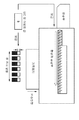
도 1a 및 도 1b는 화상 형성장치의 구성을 도시한 도면이다.
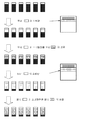
도 2a 및 도 2b는 비디오 카운트 값을 취득하는 영역을 도시한 도면이다.
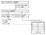
도 3은 화상 형성장치에 의해 행해지는 인쇄 처리를 나타내는 흐름도다.
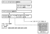
도 4는 콘트롤러와 인쇄부 사이에 행해지는 처리를 나타낸 시퀀스도이다.
도 5는 토너제의 보급을 개념적으로 도시한 도면이다.
도 6은 토너제의 보급을 개념적으로 도시한 도면이다.
도 7은 토너제를 연속 보급하는 처리를 설명하기 위한 도면이다.
도 8a 내지 도 8c는 통지 코맨드를 나타낸 도면이다.
도 9는 토너제의 보급을 개념적으로 도시한 도면이다.
도 10a 내지 도 10c는 통지 코맨드를 나타낸 도면이다. 1A and 1B are diagrams showing the configuration of an image forming apparatus.
2A and 2B are diagrams showing an area for acquiring a video count value.
3 is a flowchart showing a print process performed by the image forming apparatus.
4 is a sequence diagram showing a process performed between the controller and the printing unit.
5 is a view conceptually showing the replenishment of the toner agent.
6 is a view conceptually showing the replenishment of the toner agent.
Fig. 7 is a view for explaining a process of continuously supplying toners.
8A to 8C are diagrams showing a notification command.
9 is a view conceptually showing the replenishment of the toner agent.
10A to 10C are diagrams showing a notification command.
이하, 첨부된 도면을 참조해서 본 발명의 실시형태를 자세하게 설명한다. 이때, 이하의 실시형태는 특허청구범위에 관한 본 발명을 한정하는 것은 아니고, 또 본 실시형태에서 설명되어 있는 특징의 조합의 모두가 본 발명의 해결 수단에 필수적인 것이라고는 할 수 없다. 이때, 동일한 구성요소에는 동일한 참조번호를 붙여, 설명을 생략한다. Hereinafter, embodiments of the present invention will be described in detail with reference to the accompanying drawings. The following embodiments are not intended to limit the scope of the present invention, and all of the combinations of features described in this embodiment are not necessarily essential to the solution of the present invention. At this time, the same constituent elements are denoted by the same reference numerals, and a description thereof will be omitted.
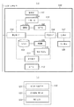
도 1a는, 본 실시형태에 있어서의 화상 형성장치(100)의 구성을 도시한 도면이다. 화상 형성장치(100)는, 예를 들면 인쇄 기능이나 판독기능, 팩시밀리(FAX0기능 등, 복수의 기능을 갖는 복합기(MFP)이다. 콘트롤러(113)는, 화상 형성장치(100)를 통괄적으로 제어하는 제어 기판이다. 콘트롤러(113)의 내부의 중앙처리장치(CPU)(101)는, 시스템 버스를 거쳐, 메모리(102), 기억부(103), 판독 전용 메모리(ROM)(104), 화상처리부(115)를 제어한다. 또한, 통신부 인터페이스(IF)(105)를 거쳐, 로컬 에어리어 네트워크(LAN)등의 네트워크(114)와 화상 형성장치(100)가 접속된다. 통신부IF(105)은, 유선 매체나 무선 매체 등, 네트워크(114)의 매체에 따른 구성을 가진다. 또한, 스캐너IF(109)를 거쳐, 판독부(110)와 콘트롤러(113)가 접속되어, 프린터IF(106)를 거쳐, 인쇄부(107) 및 카세트부(108)와, 콘트롤러(113)가 접속된다. 또한, 조작부IF(111)를 거쳐, 조작부(112)와 콘트롤러(113)가 접속된다.
1A is a diagram showing a configuration of an
화상 형성장치(100)의 기능을 실행하기 위한 각종 프로그램과 데이터는, 하드디스크나 플로피디스크 등의 기억부(103)에 기억되고 있다. 이들 프로그램이 데이터는 필요에 따라 순차 메모리(102)에 판독되어서 CPU(101)에 의해 실행된다. 기억부(103)는, 착탈가능한 기억부이거나, 화상 형성장치(100)에 내장되어서 있어도 된다. 또한, 프로그램은, 네트워크(114)를 거쳐 다른 장치로부터 다운로드되어서 기억부(103)에 격납되는 구성이어도 된다. 또한, 메모리(102)에는, 예를 들면 스태틱 랜덤 액세스 메모리(SRAM)와 같은 불휘발성메모리, 다이내믹 랜덤 액세스 메모리(DRAM)와 같은 휘발성 메모리가 사용된다. 그렇지만, 메모리(102)는, 양쪽의 메모리의 성질을 구비하고 있어도 된다. 예를 들어, 휘발성 메모리의 성질을 메모리(102)가 가지고, 불휘발 메모리의 성질을 기억부(103)가 가지는 구성이어도 된다. 이와 달리, 메모리(102)는, 화상 형성장치(100)로부터 분리가능한 메모리 매체이어도 된다.
Various programs and data for executing the functions of the
조작부(112)는, 터치패널이나 하드웨어 키 등을 구비하고 있고, CPU(101)에 의해 제공된 표시 데이터에 근거하여, 각종 유저 인터페이스 화면을 표시하고, 유저로부터의 설정과 지시의 조작을 접수한다. 조작부(112)에서 접수된 정보는, CPU(101), 메모리(102), 기억부(103) 중 어느 한개에 전송, 축적되어, 여러가지 처리에 사용된다.
The
CPU(101)은, 통신부IF(105)로부터 데이터를 판독하거나 통신부IF(105)에 대하여 데이터를 기록하는 것에 의해, 네트워크(114)에 접속된 외부의 장치와 통신가능하다. 예를 들면, CPU(101)은, 외부의 호스트 컴퓨터로부터 인쇄 잡이나 인쇄 대상의 화상 데이터를 수신하고, 잡의 실행 결과를 호스트 컴퓨터에 송신한다. 또한, 통신부IF(105)로부터 수신한 데이터는, 메모리(102) 혹은 기억부(103)에 격납되는 경우가 있다.
The
CPU(101)은, 프린터IF(106)를 거쳐, 프린터 엔진의 구성을 포함하는 인쇄부(107)와, 인쇄 데이터나 스테이터스 정보등, 각종 데이터의 송수신을 행한다. 인쇄부(107)는, 전자사진 방식의 프린터 엔진의 구성으로서, 대전, 노광, 현상, 전사, 정착의 각 프로세스에 따른 구성을 가지고, 기록 대상의 화상 데이터에 근거하여 기록 매체 위에 화상을 형성한다. 또한, CPU(101)은, 스캐너IF(109)를 거쳐, 스캐너 엔진의 구성을 포함하는 판독부(110)와, 판독 데이터나 스테이터스 정보 등, 각종 데이터의 송수신을 행한다. 판독부(110)는, 도 1에 미도시의 원고대나 자동 원고 급송장치(ADF)로부터 공급된 원고를 광학적으로 판독하는 구성을 가지고 있다. 예를 들면, 판독부(110)는 발광 다이오드(LED) 등의 광원 및 이미지센서를 가지는 이미지센서 유닛을 가진다. 판독 데이터는, 메모리(102) 혹은 기억부(103)에 격납되는 경우가 있다.
The
데이터가 통신부IF(105)나 판독부(110)로부터 취득될 뿐만 아니라, 착탈가능한 메모리(102)가 화상 형성장치(100)에 부착되는 경우에, 메모리(102)에 격납되어 있는 데이터를 취득할 경우도 있다. 또한, 기억부(103)에 기억되어 있는 데이터는 메모리(102)로 이동하거나, 혹은, 복사하는 것이 가능하다. 예를 들면, 조작부(112)를 통해 내려진 지시에 근거하여, 메모리(102)의 화상 데이터에 여러가지 부가 화상을 합성한다고 하는 것이 가능하다.
The data stored in the
도 1a의 화상 형성장치(100)는, 인쇄부(107), 판독부(110)를 구비하지만, 네트워크(114) 상에 주변기기로서 인쇄부(107), 판독부(110)가 배치되는 구성이어도 된다. 그 경우, 콘트롤러(113)가 통신부IF(105)를 거쳐 이들 주변기기를 제어한다.
Although the
화상처리부(115)는, 취득된 데이터에 대하여, 압축/해동, 보정, 변환, 편집 등, 여러가지 화상처리를 실행한다. 예를 들면, 필요에 따라, 화상처리부(115)는, 판독부(110)에서 취득된 판독 데이터나, 인쇄부(107)에 출력하는 화상 데이터에 대하여 화상처리를 행한다. 화상처리부(115)는, 하드웨어로 구성되어도 되고, 소프트웨어로 구성되어도 된다. 이와 달리, 화상처리부(115)는 하드웨어 및 소프트웨어 기능 양쪽을 겸비하고 있어도 된다.
The
또한, 본 실시형태에 있어서, 화상처리부(115)는, 도 1b에 나타낸 것과 같이, 비디오 카운트부(121), 인터럽트 제어부(122), 레지스터(123)를 가진다. 먼저, 기록 대상의 화상 데이터의 비디오 카운트 값은 비디오 카운트부(121)에 의해 취득된다. 그후, 취득된 비디오 카운트 값은 레지스터(123)에 격납되어, CPU(101)에 의해 판독된다. 인터럽트 제어부(122)는, 비디오 카운트 값이 레지스터(123)에 격납되면, CPU(101)에 대하여, 비디오 카운트 값이 레지스터(123)에 격납된 것을 나타내는 인터럽트 신호를 출력한다.
1B, the
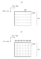
도 2a 및 도 2b는, 화상처리부(115)에서 비디오 카운트값을 취득하는 영역을 도시한 도면이다. 도 2a에 나타낸 것과 같이, 화상처리부(115)는 그것에 입력되는 화상 데이터(201)를, 부주사 방향으로 배치된 영역 203으로 분할하고 영역 203마다 비디오 카운트 값의 취득을 행한다. 부주사 방향은, 인쇄부(107)에 있어서의 기록 매체의 반송 방향에 대응한다. 각각의 비디오 카운트 값은, 예를 들면, 화소신호에 대응하는 클록 신호의 펄스수를 카운터에 의해 적산함으로써 취득된다. 각각의 비디오 카운트 값은, 화소마다의 농도에 대응한다. 따라서, 비디오 카운트 값의 취득에 의해, 인쇄부(107)에 있어서 정전잠상을 토너에 의해 현상화하기 위해 소비되는 토너량, 즉 토너 보급량을 구할 수 있다. 화상처리부(115)는, 토너 보급량과 비디오 카운트 값이 대응된 테이블을 참조하여, 화상 데이터로부터 취득한 비디오 카운트 값에 대응하는 토너 보급량에 근거하여 토너의 보급 제어 처리를 행한다. 이 테이블은, 예를 들면, 기억부(103)에 보존되어 있다.
2A and 2B are diagrams showing an area for acquiring a video count value in the
도 2a는, 화상 데이터(201)가 부주사 방향으로 배치된 5개의 영역으로 분할된 예를 나타내고 있다. 화상처리부(115)는, 화상 데이터(201)의 부주사 방향의 일단에 배치된 영역 203에서 시작하여 순차, 비디오 카운트 값을 취득한다. 예를 들면, 202 라인에 해당하는 비디오 카운트 값을 화상처리부(115)가 취득한 후, 화상처리부(115)는 취득된 값을 판독 영역 203의 비디오 카운트 값으로서 레지스터(123)에 격납한다. 그리고, 화상처리부(115)는, 비디오 카운트 값을 레지스터(123)에 격납한 것을 나타내는 인터럽트 신호를 CPU(101)에 출력한다.
2A shows an example in which the
이와 달리, 도 2b에 나타낸 것과 같이, 화상처리부(115)는, 부주사 방향 이외에, 주 주사 방향으로 화상 데이터(201)를 분할해도 된다. 주 주사 방향은, 부주사 방향에 직교하는 방향이며, 인쇄부(107)에 있어서의 현상 슬리브의 길이 방향에 대응한다. 도 2b는, 화상 데이터(201)가 부주사 및 주 주사 방향으로 배치된 더 작은 영역으로 분할되고 화상 처리부(115)이 각 영역 204 내지 209에로부터 비디오 카운트 값을 취득하는 예를 나타내고 있다. 도 2a와 마찬가지로, 화상 처리부(115)이 202라인에 해당하는 비디오 카운트 값을 취득한 후, 화상 처리부(115)은 취득된 각 값은, 영역 204 내지 209의 각각의 비디오 카운트 값으로서 레지스터(123)에 격납된다. 그리고, 화상처리부(115)는, 비디오 카운트 값을 레지스터(123)에 격납한 것을 나타내는 인터럽트 신호를 CPU(101)에 출력한다.
Alternatively, as shown in FIG. 2B, the
도 3은, 화상 형성장치(100)에 의해 행해진 인쇄 처리를 나타내는 흐름도다. 도 3의 각 처리는, 예를 들면 CPU(101)이 ROM(104)에 기억된 어플리케이션 프로그램 등을 메모리(102)에 판독해서 어플리케이션 프로그램을 실행함으로써 실현된다. 도 3의 처리는, 예를 들면, 조작부(112)를 통해 유저로부터 카피 등의 인쇄 처리의 실행의 지시를 CPU(101)이 접수하면 개시된다.
3 is a flowchart showing the print processing performed by the
스텝 S301에 있어서, CPU(101)은, 인쇄 대상의 화상 데이터에 포함되는 복수의 페이지 중 본처리의 대상 페이지에 관한 레지스터 설정을 화상처리부(115)에 대하여 지시한다. 스텝 S302에 있어서, CPU(101)은, 인쇄부(107)에 대하여 인쇄 개시 요구를 출력한다. 인쇄부(107)는, 콘트롤러(113)로부터 인쇄 개시 요구를 수신하면, 프린터 엔진의 각 부의 준비 동작을 개시한다. 준비 동작이 종료하면, 인쇄부(107)는, 콘트롤러(113)에 인쇄 개시가 가능한 것을 나타내는 인터럽트 신호를 출력한다.
In step S301, the
스텝 S303에 있어서, CPU(101)은, CPU(101)가 인터럽트 신호를 검출하였는지 판정한다. CPU(101)는 인터럽트 신호의 검출을 대기한다(스텝 S303에서 NO). CPU(101)가 인터럽트 신호를 검출하면(스텝 S303에서 YES), 스텝 S304로 처리가 진행된다. 인터럽트 신호의 예로는, 인쇄부(107)로부터 출력되는 인쇄 개시가 가능한 것을 나타내는 인터럽트 신호와, 화상처리부(115)로부터 출력되는 비디오 카운트 값이 레지스터에 격납된 것을 나타내는 인터럽트 신호를 포함한다.
In step S303, the
스텝 S304에 있어서, CPU(101)은, 검출한 인터럽트 신호를 해석하여, 인쇄 개시가 가능한 것을 나타내는 인터럽트 신호인지 아닌지를 판정한다. 인쇄 개시가 가능한 것을 나타내는 인터럽트 신호라고 판정되었을 경우(스텝 S304에서 YES), 스텝 S305로 처리를 진행한다. 스텝 S305에 있어서, CPU(101)은, 인쇄부(107)에 인쇄 개시를 지시한다. 스텝 S305의 후, 스텝 S306으로 처리가 진행된다. 스텝 S304에서, 인쇄 개시가 가능한 것을 나타내는 인터럽트 신호가 아니라고 CPU(101)가 판정한 경우(스텝 S304에서 NO), 스텝 S305의 처리를 행하지 않고 스텝 S306으로 처리가 진행된다.
In step S304, the
스텝 S306에 있어서, CPU(101)은, 검출한 인터럽트 신호를 해석하여, 비디오 카운트 값이 레지스터9123)에 격납된 것을 나타내는 인터럽트 신호인지 아닌지를 판정한다. 비디오 카운트 값이 레지스터9123)에 격납된 것을 나타내는 인터럽트 신호라고 판정되었을 경우(스텝 S306에서 YES), 스텝 S307로 처리를 진행한다. 스텝 S307에 있어서, CPU(101)은, 레지스터(123)로부터 비디오 카운트 값을 취득한다. 그리고, 스텝 S308에 있어서, CPU(101)은, 취득한 비디오 카운트 값에 근거하여 토너 보급량을 인쇄부(107)에 대하여 통지한다. 스텝 S308에서는, CPU(101)가 취득한 비디오 카운트 값을 토너 보급량으로서 인쇄부(107)에 대하여 통지하도록 해도 된다. 스텝 S308의 후, 스텝 S309로 처리가 진행된다. 스텝 S306에서, 비디오 카운트 값이 레지스터(123)에 격납된 것을 나타내는 인터럽트 신호가 아니라고 판정되었을 경우(스텝 S306에서 NO), 스텝 S309로 처리가 진행된다.
In step S306, the
화상처리부(115)는, 도 2a에 나타내는 각 영역 203으로부터 비디오 카운트 값을 비디오 카운트부(121)가 취득해서 비디오 카운트 값을 레지스터(123)에 격납할 때마다 인터럽트 신호를 출력하므로, CPU(101)은, 기록 매체의 반송 방향으로 배치된 영역 203 각각에 대해 비디오 카운트 값을 반복하여 취득하게 된다. 또한, 도 3에 나타낸 것과 같이, 인쇄부(107)에 있어서의 화상 데이터의 인쇄와, 화상처리부(115)에 의한 비디오 카운트 값의 취득 및 인쇄부(107)에의 토너 보급량의 통지는 동기하지 않고 있다.
The
스텝 S309에 있어서, CPU(101)은, 인쇄부(107)로부터의, 해당 인쇄 처리의 대상 페이지의 인쇄 종료를 나타내는 인터럽트 신호를 CPU(101)가 검출하였는지 아닌지를 판정한다. 페이지의 인쇄 종료를 나타내는 인터럽트 신호를 CPU(101)가 검출하였을 경우(스텝 S309에서 YES), 스텝 S310으로 처리를 진행한다. 스텝 S310에 있어서, CPU(101)은, 인쇄부(107)로부터의, 해당 인쇄 처리의 대상 화상 데이터의 인쇄 종료를 나타내는 인터럽트 신호를 CPU가 검출하였는지 아닌지를 판정한다. 스텝 S310에서, 화상 데이터의 인쇄 종료를 나타내는 인터럽트 신호를 CPU(101)가 검출한 경우(스텝 S310에서 YES), 스텝 S311로 처리를 진행한다. 스텝 S311에 있어서, CPU(101)은, 인쇄부(107)에 대하여 인쇄 종료 처리를 행한다. 대상 페이지의 인쇄 종료를 나타내는 인터럽트 신호를 CPU(101)가 검출하고 있지 않거나(스텝 S309에서 NO) 또는 대상 화상 데이터의 인쇄 종료를 나타내는 인터럽트 신호를 CPU(101)가 검출하고 있지 않은 경우(스텝 S310에서 NO), 스텝 303으로 처리가 되돌아가 스텝 S303로부터의 처리를 반복한다.
In step S309, the
이상과 같이, 본실시예에서는, 스텝 S303 내지 309의 처리의 반복에 의해, 스텝 S307의 비디오 카운트 값의 취득 처리가 페이지마다 복수회 행해진다. 그러한 구성에 의해, 페이지가 완전히 인쇄되기 전에 토너의 잔량이 떨어져 버리는 것에 의해, 인쇄가 정지하거나 혹은 화질이 저하한다고 하는 것을 막을 수 있다. As described above, in this embodiment, by repeating the processing of steps S303 to 309, the video count value acquisition processing of step S307 is performed plural times for each page. With such a configuration, it is possible to prevent the printing from being stopped or the image quality from deteriorating due to the remaining amount of toner falling before the page is completely printed.
예를 들면, 화상 형성장치(100)가 페이지를 인쇄하기 전의 토너 잔량이 "10"(충전 상태)을 나타낸 것으로 가정한다. 그리고, 화상 형성장치(100)가 현상화의 처리를 부주사 방향으로 1/4 및 2/1 완료한 시점에서의 토너 잔량이 각각 "8" 및 "3"이라고 가정한다. 여기에서, 화상 형성장치(100)가 현상화의 처리를 부주사 방향으로 3/4 완료한 시점에서, 토너 잔량이 "0"을 나타내는 경우에는, 인쇄가 정지하거나 혹은 화질이 저하해버린다. 그러나, 본실시예에서는, 화상 형성장치(100)가 현상화의 처리를 부주사 방향으로 1/4 완료한 시점에서의 토너 잔량이 "8"을 표시하더라도, 토너 소비량 "2"에 해당하는 동일한 양의 토너가 보급되므로, 토너 잔량이 다시 "충전 상태"를 나타낸다. 더구나, 화상 형성장치(100)가 현상화의 처리를 부주사 방향으로 1/2 완료된 시점에서 토너 잔량이 "5"를 나타내더라도, 토너 소비량 "5"에 해당하는 동일한 양의 토너가 보급되므로, 토너 잔량을 다시 "충전 상태"를 표시한다.
For example, it is assumed that the remaining toner amount before the
도 4는, 1페이지의 인쇄 처리에 있어서의 콘트롤러(113)와 인쇄부(107) 사이에서 행해지는 처리의 일례를 도시한 시퀀스도이다. 스텝 S401에 나타낸 것과 같이, 콘트롤러(113)는, 인쇄부(107)에 대하여, 인쇄 개시 요구를 통지한다. 이 스텝 S401은 도 3의 스텝 S302에 대응한다. 그리고, 스텝 S402에 나타낸 것과 같이, 인쇄부(107)가 프린터 엔진의 준비 동작을 종료하면, 인쇄부(107)는 인쇄 개시가 가능한 것을 나타내는 인터럽트 신호를 콘트롤러(113)에 출력한다. 이 스텝 S402는 도 3의 S304에서의 "YES"에 대응한다. 그리고, 스텝 S403에 나타낸 것과 같이, 인쇄부(107)는, 콘트롤러(113)의 지시에 의해 인쇄를 개시한다. 이 스텝 S403은, 도 3의 스텝 S305에 대응한다.
4 is a sequence diagram showing an example of a process performed between the
스텝 S403의 인쇄 처리가 진행함에 따라서, 스텝 S404에 나타낸 것과 같이, 콘트롤러(113)가 비디오 카운트 값이 레지스터(123)에 격납된 것을 나타내는 인터럽트 신호를 검출한다. 이 스텝 S404는 도 3의 S306에서 "YES"에 대응한다. 콘트롤러(113)가 그 인터럽트 신호를 검출하면, 콘트롤러(113)는 레지스터(123)로부터 비디오 카운트 값을 취득한다. 이 스텝 S404는 도 3의 스텝 S307에 대응한다. 그리고, 스텝 S405에 나타낸 것과 같이, 콘트롤러(113)는, 인쇄부(107)에 대하여 비디오 카운트 값에 근거하여 토너 보급량을 통지한다. 이 스텝 S405는 도 3의 스텝 S308에 대응한다. 또한, 스텝 S406에 나타낸 것과 같이, 인쇄부(107)는, 토너 보급량의 통지를 받으면, 그 토너 보급량에 대응하는 토너량을 현상기에 보급한다. 이후, 스텝 S404 내지 스텝 S406의 처리가 페이지마다 복수회 반복해서 행해진다.
As the printing process in step S403 proceeds, the
스텝 S407에 나타낸 것과 같이, 인쇄부(107)가 기록 대상의 화상 데이터의 인쇄 처리를 종료하면, 인쇄 종료를 나타내는 인터럽트 신호를 인쇄부(107)가 출력하고, 콘트롤러(113)가 그 인터럽트 신호를 검출한다. 이 스텝 S407은 도 3의 스텝 S310에서의 "YES"에 대응한다. 그리고, 스텝 S408에 나타낸 것과 같이, 콘트롤러(113)는, 인쇄부(107)에 대하여 인쇄 종료 처리를 행한다. 이 스텝 S408은 도 3의 스텝 S311에 대응한다.
As shown in step S407, when the
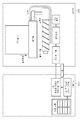
도 5 및 도 6은, 콘트롤러(113)가 비디오 카운트 값을 인쇄부(107)에 통지하고, 현상기(현상장치)에 토너제가 보급되는 처리를 나타낸 도면이다. 도 5 및 도 6에서는, 기록 매체의 반송 방향을 대응시켜서 처리를 나타내고 있다. 도 5에 나타낸 것과 같이, 콘트롤러(113)는, 기록 대상의 화상 데이터에 근거하여 영역마다 비디오 카운트 값을 취득한다. 도 5에서는, 콘트롤러(113)가 부주사 방향으로 배치된 각각의 영역으로부터 이 순서로 비디오 카운트 값 3, 5, 5, 2, 0을 취득한다. 그리고, 콘트롤러(113)은, 도 3 및 도 4에서 설명한 바와 같이, 인쇄부(107)의 프로세서에 대하여 각 영역의 비디오 카운트 값에 대응하는 토너 보급량을 순차적으로 통지해 간다.
5 and 6 are views showing a process in which the
인쇄부(107)의 프로세서가 토너 보급량의 통지를 받으면, 프로세서는 현상기에 대한 보급 신호를 출력한다. 인쇄부(107)의 프로세서는, 보급 신호에 근거하여 구동 모터를 구동시켜, 토너 보틀이나 토너 카트리지로부터 반송부를 거쳐 현상기에 토너제의 보급을 행한다.
When the processor of the
도 6은, 도 5의 현상기의 주변의 구성을 도시한 도면이다. 현상기에의 토너제의 보급이 행해지면, 현상기 내부의 현상제 공급부에는 토너제의 보급이 행해진다. 현상제 공급부는, 주 주사 방향측으로 일렬에 구성되어 있고, 정전잠상의 현상화 처리에 있어서 사용되는 토너제를 저장해 둘 수 있다. 상기한 토너 보급량에 근거하여, 일정한 양의 토너제가 현상제 공급부에 대하여 보급된다. 도 6은, 비디오 카운트 값 "3"에 근거하여 주 주사 방향측으로 일정한 양 "3"의 토너제의 보급이 행해지는 개념을 나타내고 있다. 현상제 공급부에 대한 토너제의 보급은, 현상제를 순환시키는 기구와 토너제의 보급 타이밍에 의해 제어된다. Fig. 6 is a diagram showing the configuration of the periphery of the developing device of Fig. 5; When the toner agent is replenished to the developing device, the toner replenishment is performed on the developer supplying portion inside the developing device. The developer supply portion is formed in a row in the main scanning direction and can store the toner agent used in the developing process of the electrostatic latent image. Based on the above-described toner replenishing amount, a certain amount of toner agent is replenished to the developer supplying portion. FIG. 6 shows a concept that a toner amount of "3" is supplied to the main scanning direction side on the basis of the video count value "3". The replenishment of the toner agent to the developer supply portion is controlled by the mechanism for circulating the developer and the replenishment timing of the toner agent.
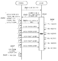
도 7은, 통지된 토너 보급량에 근거하여, 현상제 공급부에 토너제를 연속 보급하는 처리를 설명하기 위한 도면이다. 도 7 중의 최상단은 인쇄 개시전의 현상제 공급부를 나타내며, 이들 공급부에는 토너제가 충전되어 있다. 인쇄가 개시되면, 현상화의 처리가 진행함에 따라서, 현상제 공급부로부터 토너제가 소비되어 간다. Fig. 7 is a diagram for explaining the process of continuously supplying the toner to the developer supply unit based on the notified toner supply amount. Fig. The uppermost portion in Fig. 7 represents the developer supply portion before the start of printing, and these supply portions are filled with the toner. When printing is started, as the developing process proceeds, the toner is consumed from the developer supply unit.
도 7의 두 번째 상단 부분, 현상제 공급부로부터 소비되는 토너제의 양(음영 영역)을 모식적으로 나타내고 있다. 이 경우, 현상제 공급부로부터 음영 영역으로 표시된 토너제가 소비되어, 흑색으로 표시된 토너제가 남는다. 콘트롤러(113)는, 음영 영역으로 표시된 소비한 토너제에 대응하는 비디오 카운트 값을 취득하고, 토너 보급량을 인쇄부(107)에 통지한다. 인쇄부(107)는, 토너 보급량의 통지를 받으면, 도 7의 위에서 세 번째 부분에 있는 현상제 공급부에 나타낸 것과 같이, 지정된 토너 보급량에 대응하는 값에 근거하여, 현상기의 현상제 공급부에 토너제를 보급한다. 그 결과, 현상제 공급부는, 토너제가 다시 충전된다.
The second upper portion in Fig. 7, and the amount of toner (shade area) consumed from the developer supply portion. In this case, the toner material indicated as the shaded area is consumed from the developer supply part, and the toner material indicated by black is left. The
도 7의 위에서 네 번째 부분은 현상제 공급부에서 그후 소모된 토너제의 양(음영 영역)을 모식적으로 나타내고 있다. 이 경우, 현상제 공급부에 의해 음영 영역으로 표시된 토너제가 소비되어, 흑색으로 표시된 토너제가 남는다. 콘트롤러(113)는, 소비한 음영 영역으로 표시한 토너제에 대응하는 비디오 카운트 값을 취득하고, 토너 보급량을 인쇄부(107)에 통지한다. 인쇄부(107)는, 토너 보급량의 통지를 받으면, 도 7의 위에서 다섯 번째 부분에 있는 현상제 공급부에 의해 표시된 것과 같이, 통지된 토너 보급량에 근거하여, 현상기의 현상제 공급부에 토너제를 보급한다. 그 결과, 현상제 공급부는 다시 토너제로 충전된다.
The fourth portion from the top in Fig. 7 schematically shows the amount of the toner agent (shaded region) consumed subsequently in the developer supply portion. In this case, the toner supply member marked with the shaded area is consumed by the developer supply unit, and the black toner member remains. The
본실시예에서는, 상기한 바와 같이, 1페이지의 인쇄중에, 소정의 영역마다 비디오 카운트 값에 근거하여 토너 보급량을 인쇄부(107)에 통지해서, 토너제의 보급을 반복하여 행한다. 그 결과, 1페이지의 인쇄중에서 토너제가 없어져 버리는 것을 막을 수 있다. 또한, 소정의 영역 단위마다 토너의 보급이 행해지므로, 현상제 공급부의 용량을 소형화할 수 있다.
In the present embodiment, as described above, during printing of one page, the toner replenishing amount is notified to the
이상의 설명에서는, 취득한 비디오 카운트 값을 토너 보급량으로서 인쇄부(107)에 통지한다. 이하에서는, 취득한 비디오 카운트 값을 처리하고, 이 처리에 의해 얻어진 값을 토너 보급량으로서 인쇄부(107)에 통지하는 구성을 설명한다.
In the above description, the acquired video count value is notified to the
도 8a 내지 도 8c는, 콘트롤러(113)에 의해 행해진 비디오 카운트 값의 처리와, 인쇄부(107)에 대하여 송신되는 통지 코맨드의 일례를 도시한 도면이다. 도 8a는, 비디오 카운트 값의 처리를 나타내고 있다. 도 8a에서, 화상처리부(115)에 의해 취득되어서 레지스터(123)에 격납된 비디오 카운트 값(이하, 레지스터 판독값이라고 한다)은 32비트 데이터이다. 본실시형태에서는, 콘트롤러(113)는, 레지스터(123)로부터 판독한 비디오 카운트 값을 인쇄부(107)에 통지하는 것 대신에, 16비트의 데이터로 비디오 카운트 값을 변환한 후 비디오 카운트 값을 인쇄부(107)에 통지한다. 구체적으로는, 콘트롤러(113)는 32비트의 레지스터 판독값과 이전 페이지로부터의 이월된 16비트의 수치를 가산하고, 그 결과 얻어진 비디오 카운트 값의 상위 16비트 값을 인쇄부(107)에 통지하고, 하위 16비트는 다음 페이지의 처리로 이월한다.
8A to 8C are views showing an example of processing of a video count value performed by the
예를 들면, 레지스터 판독값이 0x00030105이고, 이전 페이지로부터의 이월된 16비트 값이 0x5678이었다고 하면, 가산 결과는 0x0003577D이다. 이 경우, 콘트롤러(113)는, 상위 16비트 값 0x0003을 인쇄부(107)에 통지한다. 그리고, 콘트롤러(113)는, 이월된 하위 16비트 값 0x577D를 메모리(102) 또는 기억부(103)에 격납한다. 다음 페이지의 처리시에, 콘트롤러(113)가 하위 16비트 값 0x577D를 호출해서 마찬가지로 가산을 행한다.
For example, if the register read value is 0x00030105 and the
레지스터 판독값이 0x0003FFFF이고, 이전 페이지로부터 이월된 16비트 값이 0x5678이었다고 하면, 가산 결과는, 0x00045677이 된다. 이 경우, 콘트롤러(113)는, 상위 16비트 값 0x0004를 인쇄부(107)에 통지한다. 그리고, 콘트롤러(113)는, 이월된 하위 16비트 값 0x5677을 메모리(102) 또는 기억부(103)에 격납한다. 다음 페이지의 처리시에, 콘트롤러(113)가 하위 16비트 값 0x5677을 호출해서 마찬가지로 가산을 행한다.
Assuming that the register read value is 0x0003FFFF and the 16 bit value carried over from the previous page is 0x5678, the addition result is 0x00045677. In this case, the
이에 따르면, 레지스터 판독값의 상위 비트 값에 주목한 라운딩처리를 행함으로써, 인쇄부(107)에 통지하는 데이터량을 저감시킨다. 콘트롤러(113)는 대상 페이지에 대한 나머지 부분(fraction)을 반올림(rounding off)하므로, 추가된 토너 량은 실제의 소비된 토너량보다 작은 값이 된다. 그렇지만, 다음 페이지의 처리에 나머지 부분을 이월하기 때문에, 그 차분이 보충된다.
According to this, the amount of data to be notified to the
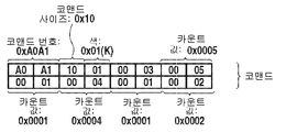
도 8b는, 1색의 비디오 카운트 값의 통지에 대한 코맨드인 통지 코맨드의 구성 예를 나타내고 있다. 콘트롤러(113)가 인쇄부(107)에 통지하는 통지 코맨드는, "코맨드 번호", "코맨드 사이즈", "색", "카운트 값" 필드로 구성된다. 도 8b에 나타내는 각각의 박스는 1바이트의 데이터를 표시한다. 코맨드 번호 필드는, 2바이트의 데이터로 표현하고, 통지 코맨드는, 0xA0A1이다. 코맨드 사이즈 필드는, 코맨드 번호를 포함하는 코맨드 전체의 데이터량을 나타내고 있고, 도 8b에서의 코맨드의 데이터량은 6바이트다. 색 필드는, 1바이트의 하위 4비트를 사용해서 각 색을 표현하고 있다. 도 8b에서는, 0x01은 흑색(K)을 표현하고 있다. 카운트 값 필드는, 도 8a에 나타낸 것과 같이 산출된 카운트 값이다.
8B shows a configuration example of a notification command which is a command for notification of a video count value of one color. The notification command that the
도 8c는, 인쇄부(107)가 황색(Y), 마젠타(M), 시안(C) 및 흑색(K)의 4색을 출력하는 칼라프린터인 경우의 통지 코맨드의 구성 예를 나타내고 있다. 도 8a와 마찬가지로, YMCK 각 색에 대해 카운트 값이 산출된다. 도 8c에서는, Y, M, C 및 K에 대해 각각 0x0001, 0x001E, 0x000A, 0x0003이 산출된다. 각 색에 대해서 카운트 값 필드가 구성되어 통지 코맨드가 12바이트 데이터인 점에서, 도 8c의 통지 코맨드가 도 8b와는 다르다.
8C shows a configuration example of a notification command when the
또한, 인쇄부(107)가 다색의 칼라프린터일 경우에도, 모노크롬 인쇄 특정한 인쇄 지정이 있었을 경우에는, 콘트롤러(113)는 특정한 출력 색에 관한 토너 보급량을 나타내는 통지 코맨드를 송신하도록 해도 된다. 본 실시형태의 동작을 특정한 인쇄 모드, 예를 들면, 고화질 인쇄 모드의 지정이 있었을 경우에 실행하도록 해도 된다.
Further, even when the
본실시형태에서는, 도 8a 내지 도 8c에 나타낸 것과 같이, 콘트롤러(113)는 레지스터 판독값으로 격납된 32비트의 데이터를 인쇄부(107)에 곧바로 통지하지 않는다. 그 대신에, 콘트롤러(113)는 32비트 데이터의 상위 비트 값에 주목해서 보다 적은 데이터량을 인쇄부(107)에 통지한다. 이에 따라, 콘트롤러(113)와 인쇄부(107) 사이의 데이터 통신량을 저감시킬 수 있다.
In the present embodiment, as shown in Figs. 8A to 8C, the
도 9와 도 10a 내지 도 10c는, 도 2b에 나타낸 것과 같이, 주 주사 방향으로 배치된 영역 각각에서 비디오 카운트 값을 취득할 경우의, 비디오 카운트 값의 처리와 통지 코맨드의 일례를 도시한 도면이다. 도 9는, 도 6에서 나타낸 보급 제어가, 주 주사 방향으로 배치된 6개의 영역에 대응하는 비디오 카운트 값에 근거해서 행해지는 예를 나타내고 있다. 9 and 10A to 10C are diagrams showing an example of processing of a video count value and an example of a notification command in the case of acquiring a video count value in each of the areas arranged in the main scanning direction as shown in FIG. 2B . Fig. 9 shows an example in which the replenishment control shown in Fig. 6 is performed based on video count values corresponding to the six regions arranged in the main scanning direction.
도 9는, 주 주사 방향으로 배치된 6개의 영역으로 각각의 영역 203이 분할되어 있는 점에서 도 6과 다르지만, 각 영역에 대해 행해지는 보급 제어 처리는, 도 6에 있어서의 설명과 같다. 도 9와 같은 구성은, 예를 들면, 복수의 현상제 공급부가 주 주사 방향으로 배치되는 경우에 적용되어도 된다. 도 9에 나타낸 것과 같이, 각 현상제 공급부에 의한 소비량인, 주 주사 방향으로 배치된 각 영역에 대응하는 토너 소비량 3, 5, 1, 4, 1, 2가 인쇄부(107)에 통지된다.
Fig. 9 differs from Fig. 6 in that each
도 10a 내지 도 10c는, 주 주사 방향으로 배치된 각 영역으로부터 비디오 카운트 값을 취득할 경우의, 콘트롤러(113)에 의해 행해진 비디오 카운트 값의 처리와, 인쇄부(107)에 대하여 송신되는 통지 코맨드의 일례를 도시한 도면이다. 대응하는 레지스터 판독값으로부터의 비디오 카운트 값의 처리는, 도 8a를 참조하여 설명한 것과 같다. 그러나, 도 10a에서는, 도 8a에 나타낸 1개의 영역을 도 8a의 수직 방향으로 분할하여 얻어진 6개의 영역으로부터 취득한 비디오 카운트 값이, 레지스터(123)에 격납되어 있다.
Figs. 10A to 10C are diagrams for explaining the processing of the video count value performed by the
도 10a의 경우, CPU(101)은, 도 3의 스텝 S306에서 1개의 인터럽트 신호가 검출될 때마다, 6개의 영역의 레지스터 판독값을 판독하고, 각각의 카운트 값(토너 보급량)의 산출을 행한다. 도 10a에서, 산출된 각 영역의 비디오 카운트 값이 0x0003, 0x0005, 0x0001, 0x0004, 0x0001, 0x0002이다.
In the case of Fig. 10A, each time one interrupt signal is detected in step S306 in Fig. 3, the
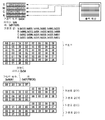
도 10b는, 도 10a의 카운트 값에 근거하는 통지 코맨드의 구성 예를 나타내고 있다. 각 필드의 구성은 도 8b에서 나타낸 것과 같지만, 카운트 값의 필드는 6개의 영역을 포함하도록 확장된다. 따라서, 코맨드 사이즈도, 도 8b에서 나타낸 것보다도 커지고 있다. FIG. 10B shows a configuration example of a notification command based on the count value in FIG. 10A. The configuration of each field is the same as that shown in Fig. 8B, but the field of the count value is expanded to include six areas. Therefore, the command size is also larger than that shown in Fig. 8B.
도 10c는, 인쇄부(107)가 YMCK의 4색을 출력하는 칼라프린터인 경우의 통지 코맨드의 구성 예를 나타내고 있다. 도 10c에 나타낸 것과 같이, YMCK 각 색에 대해 영역에 대응하는 카운트 값이 취득된다. 코맨드의 구성도, 도 8c에 나타낸 것과 동일하지만, 카운트 값의 필드가 24 영역 전체(6개의 영역 각각은 4개의 색 YMCK로 표시된다)를 포함하도록 확장된다. 이들 코맨드를 인쇄부(107)에 통지함으로써, 주 주사 방향으로 배치된 각 색의 현상제 공급부 각각에게 적절한 양의 토너제가 보급될 수 있다.
10C shows a configuration example of a notification command when the
기타 실시형태Other embodiments
본 발명의 실시형태는, 본 발명의 전술한 실시형태(들)의 1개 이상의 기능을 수행하기 위해 기억매체('비일시적인 컴퓨터 판독가능한 기억매체'로서 더 상세히 언급해도 된다)에 기록된 컴퓨터 실행가능한 명령(예를 들어, 1개 이상의 프로그램)을 판독하여 실행하거나 및/또는 전술한 실시예(들)의 1개 이상의 기능을 수행하는 1개 이상의 회로(예를 들어, 주문형 반도체 회로(ASIC)를 포함하는 시스템 또는 장치의 컴퓨터나, 예를 들면, 전술한 실시형태(들)의 1개 이상의 기능을 수행하기 위해 기억매체로부터 컴퓨터 실행가능한 명령을 판독하여 실행함으로써, 시스템 또는 장치의 컴퓨터에 의해 수행되는 방법에 의해 구현될 수도 있다. 컴퓨터는, 1개 이상의 중앙처리장치(CPU), 마이크로 처리장치(MPU) 또는 기타 회로를 구비하고, 별개의 컴퓨터들의 네트워크 또는 별개의 컴퓨터 프로세서들을 구비해도 된다. 컴퓨터 실행가능한 명령은, 예를 들어, 기억매체의 네트워크로부터 컴퓨터로 주어져도 된다. 기록매체는, 예를 들면, 1개 이상의 하드디스크, 랜덤 액세스 메모리(RAM), 판독 전용 메모리(ROM), 분산 컴퓨팅 시스템의 스토리지, 광 디스크(콤팩트 디스크(CD), 디지털 다기능 디스크(DVD), 또는 블루레이 디스크(BD)TM 등), 플래시 메모리소자, 메모리 카드 등을 구비해도 된다.Embodiments of the present invention may be practiced using computer executable programs (e.g., computer readable instructions) recorded on a storage medium (which may be referred to as " non-volatile computer readable storage medium ") for performing one or more functions of the above- (E.g., an application specific integrated circuit (ASIC)) that reads and executes possible instructions (e.g., one or more programs) and / or performs one or more functions of the above- For example, by reading and executing computer-executable instructions from a storage medium to perform one or more functions of the above-described embodiment (s), such as by a computer of the system or apparatus The computer may comprise one or more central processing units (CPUs), microprocessors (MPUs), or other circuitry, and may be implemented in a network of discrete computers The computer-executable instructions may, for example, be presented to a computer from a network of storage media. The storage medium may comprise, for example, one or more hard disks, a random access memory RAM), read only memory (ROM), a distributed computing system storage, an optical disk (a compact disc (CD), digital versatile disk (DVD), or Blu-ray disc (BD), TM, etc.), flash memory device, a memory card, etc. .
본 발명은, 상기한 실시형태의 1개 이상의 기능을 실현하는 프로그램을, 네트워크 또는 기억매체를 개입하여 시스템 혹은 장치에 공급하고, 그 시스템 혹은 장치의 컴퓨터에 있어서 1개 이상의 프로세서가 프로그램을 읽어 실행하는 처리에서도 실행가능하다. 또한, 1개 이상의 기능을 실현하는 회로(예를 들어, ASIC)에 의해서도 실행가능하다. The present invention provides a program or a program for realizing one or more functions of the above-described embodiments to a system or an apparatus via a network or a storage medium, and in the computer of the system or apparatus, . It may also be implemented by a circuit (for example, an ASIC) that realizes one or more functions.
예시적인 실시형태들을 참조하여 본 발명을 설명하였지만, 본 발명이 이러한 실시형태에 한정되지 않는다는 것은 자명하다. 이하의 청구범위의 보호범위는 가장 넓게 해석되어 모든 변형, 동등물 구조 및 기능을 포괄하여야 한다. While the present invention has been described with reference to exemplary embodiments, it is to be understood that the invention is not limited to those embodiments. The scope of the following claims is to be accorded the broadest interpretation so as to encompass all such modifications, equivalent structures and functions.
Claims (11)
상기 취득부에 의해 상기 비디오 카운트 값이 취득되는 상기 기록매체의 영역에 대해서 화상이 형성되면, 해당 영역으로부터 취득된 상기 비디오 카운트 값에 대응하는 양의 토너로 현상부에 보급하도록, 상기 취득부에 의해 취득된 상기 비디오 카운트 값을 사용해서 제어를 행하도록 구성된 제어부를 구비한 화상 형성장치.
An acquisition unit configured to acquire a video count value for each predetermined unit area in a transport direction of the recording medium based on image data to be recorded;
Wherein when the image is formed in the area of the recording medium on which the video count value is acquired by the acquisition unit, the acquisition unit acquires the video count value from the acquisition unit so as to supply the development unit with the positive toner corresponding to the video count value acquired from the area And a control unit configured to perform control using the video count value acquired by the video count value acquiring unit.
상기 취득부는, 상기 미리 정해진 단위 영역을 분할하여 얻어진 각각의 영역으로부터 비디오 카운트 값을 취득하는 화상 형성장치.
The method according to claim 1,
Wherein the acquisition unit acquires a video count value from each of the areas obtained by dividing the predetermined unit area.
상기 미리 정해진 단위 영역은, 상기 화상 데이터의 페이지보다 작은 화상 형성장치.
The method according to claim 1,
Wherein the predetermined unit area is smaller than a page of the image data.
상기 기록 매체에 화상을 형성하도록 구성되고 상기 현상부를 구비한 화상 형성부를 더 구비하고,
상기 제어부는, 상기 취득부에 의해 취득된 상기 비디오 카운트 값을 사용해서 상기 화상 형성부를 제어하는 화상 형성장치.
The method according to claim 1,
Further comprising an image forming unit configured to form an image on the recording medium and having the developing unit,
Wherein the control unit controls the image forming unit using the video count value acquired by the acquisition unit.
상기 화상 형성부는, 토너 보틀로부터 토너를 상기 현상부에 반송하도록 구성된 기구를 구비한 화상 형성장치.
5. The method of claim 4,
Wherein the image forming section has a mechanism configured to convey the toner from the toner bottle to the developing section.
상기 제어부는, 상기 취득부에 의해 취득된 상기 비디오 카운트 값에 대응하는 상기 토너의 보급량을 나타내는 데이터를 상기 화상 형성부에 출력하는 화상 형성장치.
5. The method of claim 4,
Wherein the control section outputs to the image forming section data indicating the amount of supply of the toner corresponding to the video count value acquired by the acquisition section.
상기 제어부는, 상기 화상 데이터에 근거하여 상기 기록 매체 상에의 화상의 기록을 개시하도록 상기 화상 형성부에게 요구하는 화상 형성장치.
The method according to claim 6,
Wherein the control unit requests the image forming unit to start recording of an image on the recording medium based on the image data.
상기 요구의 타이밍과 상기 출력의 타이밍이 서로 다른 화상 형성장치.
8. The method of claim 7,
Wherein the timing of the request is different from the timing of the output.
상기 취득부에 의해 취득된 상기 비디오 카운트 값의 나머지 부분(fraction)을 반올림(rounding off)하는 라운딩처리를 행하도록 구성된 처리부를 더 구비하고,
상기 제어부는, 상기 처리부에 의해 상기 비디오 카운트 값에 대하여 행해진 상기 라운딩처리된 데이터를, 상기 토너의 보급량을 나타내는 데이터로서, 상기 화상 형성부에 출력하는 화상 형성장치.
The method according to claim 6,
Further comprising a processing unit configured to perform a rounding process for rounding off a remaining fraction of the video count value acquired by the acquisition unit,
And the control section outputs the rounded data, which has been performed by the processing section to the video count value, to the image forming section as data indicating the toner supply amount.
상기 토너의 보급량을 나타내는 데이터는, 상기 비디오 카운트 값을 나타내는 데이터보다도 데이터량이 더 적은 화상 형성장치.
10. The method of claim 9,
Wherein the data indicating the amount of toner supply is smaller than the data indicating the video count value.
기록 대상의 화상 데이터에 근거하여, 상기 기록 매체의 반송 방향에서 미리 정해진 단위 영역마다 비디오 카운트 값을 취득하는 단계와,
상기 비디오 카운트 값이 취득되는 상기 기록매체의 영역에 대해서 화상이 형성되면, 해당 영역으로부터 취득된 상기 비디오 카운트 값에 대응하는 양의 토너로 현상부에 보급하도록, 취득된 상기 비디오 카운트 값을 사용해서 제어를 행하는 단계를 포함하는 제어방법.A control method executed in an image forming apparatus for forming an image on a recording medium,
Acquiring a video count value for each predetermined unit area in the transport direction of the recording medium based on the image data to be recorded;
When the image is formed in the area of the recording medium from which the video count value is acquired, the acquired video count value is used to supply the developing unit with the positive toner corresponding to the video count value acquired from the area And performing control.
Applications Claiming Priority (2)
| Application Number | Priority Date | Filing Date | Title |
|---|---|---|---|
| JP2017033724A JP2018138975A (en) | 2017-02-24 | 2017-02-24 | Image forming apparatus and control method |
| JPJP-P-2017-033724 | 2017-02-24 |
Publications (1)
| Publication Number | Publication Date |
|---|---|
| KR20180098137A true KR20180098137A (en) | 2018-09-03 |
Family
ID=63246763
Family Applications (1)
| Application Number | Title | Priority Date | Filing Date |
|---|---|---|---|
| KR1020180017360A Ceased KR20180098137A (en) | 2017-02-24 | 2018-02-13 | Image forming apparatus and control method |
Country Status (3)
| Country | Link |
|---|---|
| US (2) | US10108124B2 (en) |
| JP (1) | JP2018138975A (en) |
| KR (1) | KR20180098137A (en) |
Families Citing this family (1)
| Publication number | Priority date | Publication date | Assignee | Title |
|---|---|---|---|---|
| JP7341762B2 (en) * | 2019-07-11 | 2023-09-11 | キヤノン株式会社 | Control device, image forming device, information processing device, control method, and program |
Family Cites Families (7)
| Publication number | Priority date | Publication date | Assignee | Title |
|---|---|---|---|---|
| JP4298329B2 (en) * | 2003-03-10 | 2009-07-15 | キヤノン株式会社 | Image forming apparatus |
| JP4218951B2 (en) * | 2003-09-19 | 2009-02-04 | キヤノン株式会社 | Image forming apparatus, control method, and control program |
| KR101200415B1 (en) * | 2007-10-25 | 2012-11-13 | 삼성전자주식회사 | Image forming apparatus and control method of the same |
| JP2010015018A (en) * | 2008-07-04 | 2010-01-21 | Kyocera Mita Corp | Image forming apparatus |
| JP5751814B2 (en) * | 2010-12-08 | 2015-07-22 | キヤノン株式会社 | Image forming apparatus, control method, and program |
| US20120168461A1 (en) * | 2011-01-05 | 2012-07-05 | Diversapack Llc | Reuseable housing for flexible pouch with fitment |
| JP5691603B2 (en) * | 2011-02-16 | 2015-04-01 | 富士ゼロックス株式会社 | Image processing apparatus and program |
-
2017
- 2017-02-24 JP JP2017033724A patent/JP2018138975A/en active Pending
-
2018
- 2018-02-08 US US15/892,277 patent/US10108124B2/en active Active
- 2018-02-13 KR KR1020180017360A patent/KR20180098137A/en not_active Ceased
- 2018-10-15 US US16/160,273 patent/US10656584B2/en active Active
Also Published As
| Publication number | Publication date |
|---|---|
| US10656584B2 (en) | 2020-05-19 |
| US20180246453A1 (en) | 2018-08-30 |
| US20190049886A1 (en) | 2019-02-14 |
| US10108124B2 (en) | 2018-10-23 |
| JP2018138975A (en) | 2018-09-06 |
Similar Documents
| Publication | Publication Date | Title |
|---|---|---|
| US8699900B2 (en) | Image processing apparatus and density correction method | |
| JP6201557B2 (en) | Image forming apparatus | |
| JP4424357B2 (en) | Image forming apparatus, image forming method, and image forming program | |
| US10656584B2 (en) | Image forming apparatus and control method | |
| JP5446341B2 (en) | Image forming apparatus, image forming method, and control program | |
| US8411314B2 (en) | Image forming apparatus for forming an image by transferring an image onto an intermediate transfer member, image forming method, and storage medium | |
| JP2012155218A (en) | Image forming apparatus | |
| JP5079065B2 (en) | Color image processing apparatus and program | |
| JP5523384B2 (en) | Image forming apparatus and toner density control method | |
| US20200045203A1 (en) | Image forming apparatus, image processing method, and storage medium | |
| JP2001222145A (en) | Color image forming equipment | |
| KR100727936B1 (en) | A computer-readable recording medium comprising a halftone processing method of a printer employing a three-level developing method, a printing method suitable for the same, and a program suitable for the same. | |
| US11030499B2 (en) | Image forming apparatus, method of controlling the same, and storage medium | |
| JP5740991B2 (en) | Image processing apparatus and image processing method | |
| JP5932730B2 (en) | Image forming apparatus | |
| JP7630963B2 (en) | Image forming device | |
| JPH10186768A (en) | Image forming device | |
| JP2009217058A (en) | Image forming apparatus and method for controlling the same | |
| JP4709061B2 (en) | Image forming apparatus, image forming apparatus control method, and control program | |
| JP2025134450A (en) | Image forming apparatus and control method for image forming apparatus | |
| JP5777584B2 (en) | Image processing device | |
| JP6364934B2 (en) | Writing processing apparatus, writing processing system, optical scanning apparatus, image forming apparatus, and image forming method | |
| US20180129148A1 (en) | Image forming apparatus, control method thereof, and storage medium | |
| JP2012063594A (en) | Image forming apparatus and method for controlling the same | |
| JP2005062523A (en) | Image forming apparatus |
Legal Events
| Date | Code | Title | Description |
|---|---|---|---|
| PA0109 | Patent application |
Patent event code: PA01091R01D Comment text: Patent Application Patent event date: 20180213 |
|
| PG1501 | Laying open of application | ||
| A201 | Request for examination | ||
| PA0201 | Request for examination |
Patent event code: PA02012R01D Patent event date: 20190813 Comment text: Request for Examination of Application Patent event code: PA02011R01I Patent event date: 20180213 Comment text: Patent Application |
|
| E902 | Notification of reason for refusal | ||
| PE0902 | Notice of grounds for rejection |
Comment text: Notification of reason for refusal Patent event date: 20200512 Patent event code: PE09021S01D |
|
| E601 | Decision to refuse application | ||
| PE0601 | Decision on rejection of patent |
Patent event date: 20201224 Comment text: Decision to Refuse Application Patent event code: PE06012S01D Patent event date: 20200512 Comment text: Notification of reason for refusal Patent event code: PE06011S01I |