JP5751814B2 - Image forming apparatus, control method, and program - Google Patents
Image forming apparatus, control method, and program Download PDFInfo
- Publication number
- JP5751814B2 JP5751814B2 JP2010273943A JP2010273943A JP5751814B2 JP 5751814 B2 JP5751814 B2 JP 5751814B2 JP 2010273943 A JP2010273943 A JP 2010273943A JP 2010273943 A JP2010273943 A JP 2010273943A JP 5751814 B2 JP5751814 B2 JP 5751814B2
- Authority
- JP
- Japan
- Prior art keywords
- color component
- data
- image
- color
- unit
- Prior art date
- Legal status (The legal status is an assumption and is not a legal conclusion. Google has not performed a legal analysis and makes no representation as to the accuracy of the status listed.)
- Expired - Fee Related
Links
Images


Classifications
-
- G—PHYSICS
- G03—PHOTOGRAPHY; CINEMATOGRAPHY; ANALOGOUS TECHNIQUES USING WAVES OTHER THAN OPTICAL WAVES; ELECTROGRAPHY; HOLOGRAPHY
- G03G—ELECTROGRAPHY; ELECTROPHOTOGRAPHY; MAGNETOGRAPHY
- G03G15/00—Apparatus for electrographic processes using a charge pattern
- G03G15/01—Apparatus for electrographic processes using a charge pattern for producing multicoloured copies
- G03G15/0142—Structure of complete machines
- G03G15/0178—Structure of complete machines using more than one reusable electrographic recording member, e.g. one for every monocolour image
- G03G15/0189—Structure of complete machines using more than one reusable electrographic recording member, e.g. one for every monocolour image primary transfer to an intermediate transfer belt
-
- G—PHYSICS
- G03—PHOTOGRAPHY; CINEMATOGRAPHY; ANALOGOUS TECHNIQUES USING WAVES OTHER THAN OPTICAL WAVES; ELECTROGRAPHY; HOLOGRAPHY
- G03G—ELECTROGRAPHY; ELECTROPHOTOGRAPHY; MAGNETOGRAPHY
- G03G15/00—Apparatus for electrographic processes using a charge pattern
- G03G15/01—Apparatus for electrographic processes using a charge pattern for producing multicoloured copies
- G03G15/0105—Details of unit
- G03G15/0121—Details of unit for developing
-
- G—PHYSICS
- G03—PHOTOGRAPHY; CINEMATOGRAPHY; ANALOGOUS TECHNIQUES USING WAVES OTHER THAN OPTICAL WAVES; ELECTROGRAPHY; HOLOGRAPHY
- G03G—ELECTROGRAPHY; ELECTROPHOTOGRAPHY; MAGNETOGRAPHY
- G03G15/00—Apparatus for electrographic processes using a charge pattern
- G03G15/50—Machine control of apparatus for electrographic processes using a charge pattern, e.g. regulating differents parts of the machine, multimode copiers, microprocessor control
- G03G15/5075—Remote control machines, e.g. by a host
- G03G15/5079—Remote control machines, e.g. by a host for maintenance
-
- G—PHYSICS
- G03—PHOTOGRAPHY; CINEMATOGRAPHY; ANALOGOUS TECHNIQUES USING WAVES OTHER THAN OPTICAL WAVES; ELECTROGRAPHY; HOLOGRAPHY
- G03G—ELECTROGRAPHY; ELECTROPHOTOGRAPHY; MAGNETOGRAPHY
- G03G15/00—Apparatus for electrographic processes using a charge pattern
- G03G15/55—Self-diagnostics; Malfunction or lifetime display
- G03G15/553—Monitoring or warning means for exhaustion or lifetime end of consumables, e.g. indication of insufficient copy sheet quantity for a job
- G03G15/556—Monitoring or warning means for exhaustion or lifetime end of consumables, e.g. indication of insufficient copy sheet quantity for a job for toner consumption, e.g. pixel counting, toner coverage detection or toner density measurement
-
- G—PHYSICS
- G03—PHOTOGRAPHY; CINEMATOGRAPHY; ANALOGOUS TECHNIQUES USING WAVES OTHER THAN OPTICAL WAVES; ELECTROGRAPHY; HOLOGRAPHY
- G03G—ELECTROGRAPHY; ELECTROPHOTOGRAPHY; MAGNETOGRAPHY
- G03G15/00—Apparatus for electrographic processes using a charge pattern
- G03G15/55—Self-diagnostics; Malfunction or lifetime display
- G03G15/553—Monitoring or warning means for exhaustion or lifetime end of consumables, e.g. indication of insufficient copy sheet quantity for a job
Description
本発明はビデオカウントを利用したトナー補給制御を行う画像処理装置、制御方法、およびプログラムに関する。 The present invention relates to an image processing apparatus, a control method, and a program for performing toner supply control using video count.
一般に、電子写真方式や静電記録方式の画像形成装置が具備する現像装置には、トナー粒子とキャリア粒子とを主成分とした二成分現像剤が用いられている。特に、電子写真方式によりフルカラーやマルチカラー画像を形成するカラー画像形成装置には、画像の色味などの観点から、殆どの現像装置が二成分現像剤を使用している。この二成分現像剤のトナー濃度(即ち、キャリア粒子とトナー粒子との合計重量に対するトナー粒子の重量の割合)は画像品質を安定化させる上で極めて重要な要素である。現像剤のトナー粒子は現像時に消費され、トナー濃度は変化する。このため、現像剤濃度制御装置(ATR)を使用して適時現像剤のトナー濃度を正確に検出し、その変化に応じてトナー補給を行い、トナー濃度を常に一定に制御し、画像の品位を保持する必要がある。 In general, a two-component developer containing toner particles and carrier particles as main components is used in a developing device provided in an electrophotographic or electrostatic recording image forming apparatus. Particularly, in a color image forming apparatus that forms a full-color or multi-color image by an electrophotographic method, most developing devices use a two-component developer from the viewpoint of the color of the image. The toner concentration of this two-component developer (that is, the ratio of the weight of toner particles to the total weight of carrier particles and toner particles) is an extremely important factor in stabilizing the image quality. The toner particles of the developer are consumed during development, and the toner density changes. For this reason, the developer concentration control device (ATR) is used to accurately detect the toner concentration of the developer in a timely manner, and the toner is replenished in accordance with the change, and the toner concentration is always controlled to be constant, thereby improving the image quality. Need to hold.
このような現像により現像装置内のトナー濃度が変化するのを補正するために、現像装置において、現像時に補給するトナー量を制御する、現像容器中のトナー濃度検知装置および濃度制御装置は様々な方式のものが実用化されている。 In order to correct the change in the toner density in the developing device due to such development, there are various toner density detecting devices and density control devices in the developing container that control the amount of toner replenished during development in the developing device. The system has been put into practical use.
方式の一例として、現像剤担持体や現像剤容器の現像剤搬送経路に近接し、現像剤担持体上に搬送された現像剤、あるいは現像容器内の現像剤に光を当てたときの反射率がトナー濃度により異なることを利用する。なお、現像剤担持体は、一般に現像スリーブが用いられる場合が多いので以下「現像スリーブ」と記述する。このインダクタンス検知方式では、トナー濃度を検知し制御する現像剤濃度制御装置、あるいは現像剤の側壁に磁性キャリアと非磁性トナーの混合比率による見かけの透磁率を検知して電気信号に変換するインダクタンスヘッドからの検出信号により、現像器内のトナーの実際の濃度を検知する。そして、検知した濃度と基準値との比較によりトナーを補給する。 As an example of the system, the reflectance when light is applied to the developer transported on the developer carrier or the developer in the developer container in the vicinity of the developer transport path of the developer carrier or developer container Is different depending on the toner density. In addition, since a developing sleeve is generally used as the developer carrying member, it is hereinafter referred to as “developing sleeve”. In this inductance detection method, a developer concentration control device that detects and controls the toner concentration, or an inductance head that detects an apparent magnetic permeability due to the mixing ratio of the magnetic carrier and nonmagnetic toner on the side wall of the developer and converts it into an electric signal. The actual density of the toner in the developing device is detected by the detection signal from. Then, the toner is replenished by comparing the detected density with a reference value.
また、別の方式として、以下のような方式がある。像担持体上に形成したパッチ画像濃度を、その表面に対向した位置に設けた光源から光を照射し、その反射光を受けるセンサーにより読み取る。そして、アナログ−ディジタル変換器でディジタル信号に変換した後CPUに送り、読み取った値が初期設定値より濃度が高い場合、初期設定値に戻るまでトナー補給が停止される。初期設定値より濃度が低ければ初期設定値に戻るまで強制的にトナーが補給され、その結果トナー濃度が間接的に所望の値に維持される方式などがある。なお、像担持体は、一般に感光ドラムが用いられる場合が多いので以下「感光ドラム」と記述する。 Another method is as follows. The patch image density formed on the image carrier is read by a sensor which receives light from a light source provided at a position facing the surface and receives the reflected light. Then, after being converted into a digital signal by an analog-digital converter and sent to the CPU, if the read value has a density higher than the initial set value, toner supply is stopped until the value returns to the initial set value. If the density is lower than the initial set value, the toner is forcibly replenished until it returns to the initial set value, and as a result, the toner density is indirectly maintained at a desired value. In general, a photosensitive drum is often used as the image carrier.
しかし、現像スリーブ上に搬送された現像剤あるいは現像容器内の現像剤に光を当てた際の反射率からトナー濃度を検知する方式は、トナー飛散等により検知手段が汚れてしまった場合、正確にトナー濃度を検知できないなどの問題がある。 However, the method of detecting the toner density from the reflectance when light is applied to the developer conveyed on the developing sleeve or the developer in the developing container is accurate when the detecting means becomes dirty due to toner scattering or the like. There is a problem that the toner density cannot be detected.
また、インダクタンス検知方式のATRは、画像形成装置の動作停止直前もしくは動作再開直後における、現像剤の放置や環境の変動による現像剤のかさ密度の変化により、見かけ透磁率に対応したセンサー検出信号が不連続に変化するという問題がある。 The inductance detection type ATR has a sensor detection signal corresponding to the apparent permeability due to a change in the bulk density of the developer due to leaving of the developer or a change in environment immediately before the operation of the image forming apparatus is stopped or immediately after the operation is restarted. There is a problem that it changes discontinuously.
また、パッチ画像濃度から間接的にトナー濃度を制御する方式は、複写機、あるいは画像形成装置の小型化に伴い、パッチ画像を形成するスペースや検知手段を設置するスペースが確保できない等の問題がある。 In addition, the method of indirectly controlling the toner density from the patch image density has a problem that a space for forming a patch image and a space for installing a detection unit cannot be secured as the copying machine or the image forming apparatus is downsized. is there.
そこで、これらの問題点が生じない方式として、ビデオカウントを利用したトナー補給方式が実用化されている(例えば、特許文献1参照)。これは、現像により低下する現像器内のトナー濃度を一定に保つために、画素毎のディジタル画像信号の出力レベルを積算して出力画像の印字比率を求め、この求められた印字比率から消費されるトナー量を計算して、現像時のトナーを補給する。即ち、画像処理時の多値のビデオデータや、中間調処理後の2値のビデオデータ等を画素毎にその階調値やドット数のビデオカウントをトナー補給量に変換する。そして、変換されたトナー補給量をCPUに送る。CPUは、このトナー補給量に基づいてトナー補給信号を所定時間送信する。これにより、トナー補給装置を駆動し、現像剤容器内に必要量のトナー量を補給することによって、現像剤容器内のトナー濃度を一定に保つ。 Therefore, a toner replenishing method using a video count has been put to practical use as a method that does not cause these problems (for example, see Patent Document 1). In order to keep the toner density in the developing device, which is lowered by development, constant, the output level of the digital image signal for each pixel is integrated to obtain the print ratio of the output image, which is consumed from the obtained print ratio. The toner amount to be developed is calculated, and the toner during development is replenished. That is, for each pixel, multi-value video data at the time of image processing, binary video data after halftone processing, and the like are converted into a toner replenishment amount. Then, the converted toner supply amount is sent to the CPU. The CPU transmits a toner replenishment signal for a predetermined time based on the toner replenishment amount. Thus, the toner replenishing device is driven to supply a necessary amount of toner in the developer container, thereby keeping the toner concentration in the developer container constant.
しかしながら、特許文献1では、画像処理中のビデオデータより積算したビデオカウント値に基づいて生成されたトナー補給量の値をCPUに一旦送信し、トナー補給信号としてCPUより出力し、トナー補給装置を駆動させる。この場合、CPUによるソフトウェア処理が介在するため、補給対象のビデオデータより形成される現像タイミングと実際のトナー補給動作タイミングとの間にずれが生じるという課題がある。
However, in
さらに、静電潜像を形成するためのドラムをタンデムに配置したタンデム式エンジンの場合は、多値の画像データに中間調処理を行い2値の各色成分データに展開された後、各ドラムへ静電潜像を形成するタイミングで順次送信される。このタイミングは実際には各色成分のドラムステーションの距離と印字速度に基づく時間差であり、実際の各色トナーはこの時間差にて順次消費される。例えば、ドラムステーションがYMCK(イエロー、マゼンタ、シアン、ブラック)の順に配設されている場合を考える。この場合において、最終段のKのドラムに1ページ目の静電潜像を形成している際に、Yのドラムに次の印字対象である2ページ目の静電潜像をしていると、YMCKのトナー補給動作を同時に行う制御では、必ず静電潜像の形成に時間差が生じる。つまり、タンデム式エンジンにおいて、上流に配置されたドラムと下流に配置されたドラムとの間には現像における時間差があり、いずれかにトナー補給のタイミングを合わせると、補給対象ページとトナー補給タイミングがずれるという問題も生じる。 Further, in the case of a tandem engine in which drums for forming an electrostatic latent image are arranged in tandem, halftone processing is performed on multi-valued image data and developed into binary color component data, and then to each drum. Sequentially transmitted at the timing of forming the electrostatic latent image. This timing is actually a time difference based on the distance between the drum stations of each color component and the printing speed, and each actual color toner is sequentially consumed at this time difference. For example, consider a case where drum stations are arranged in the order of YMCK (yellow, magenta, cyan, black). In this case, when the electrostatic latent image of the first page is formed on the K drum in the final stage, the electrostatic latent image of the second page that is the next print target is formed on the Y drum. In the control in which YMCK toner replenishment operation is performed simultaneously, there is always a time difference in the formation of the electrostatic latent image. In other words, in a tandem engine, there is a time difference in development between the drum arranged upstream and the drum arranged downstream, and when the timing of toner replenishment is matched to either, the replenishment target page and the toner replenishment timing are There is also a problem of shifting.
本発明は、画素毎の色成分のカウント値を直接各色成分のビデオデータに付加してプリンタエンジン側に送信し、トナー補給タイミングの時間差をなくすことで適正なタイミングでのトナー補給を可能とする画像形成装置を提供することを目的とする。 In the present invention, the count value of the color component for each pixel is directly added to the video data of each color component and transmitted to the printer engine side, so that toner replenishment at an appropriate timing is possible by eliminating the time difference of the toner replenishment timing. An object is to provide an image forming apparatus.
上記課題を解決するために、本発明は以下の構成を有する。すなわち、色成分に対応した現像装置を有する画像形成装置であって、画像データの所定の範囲に含まれる各画素が有する各色成分の値を色成分毎に積算し、当該積算した値を各色成分のカウント値に変換する変換手段と、前記変換手段にて変換された各色成分のカウント値のうち第1の色成分のカウント値を、前記画像データの前記第1の色成分のデータに付加し、前記各色成分のカウント値のうち第2の色成分のカウント値を、前記画像データの前記第2の色成分のデータに付加する付加手段と、前記第1の色成分のデータと前記第2の色成分のデータに基づき画像形成を行う際、前記付加手段にて付加された各色成分のカウント値に応じて、色成分ごとの現像装置にトナーを補給する制御手段とを有する。
In order to solve the above problems, the present invention has the following configuration. That is, an image forming apparatus having a developing device corresponding to a color component, the value of each color component included in each pixel included in a predetermined range of image data is integrated for each color component, and the integrated value is calculated for each color component. Conversion means for converting to the count value of the first color component, and the count value of the first color component among the count values of the color components converted by the conversion means is added to the data of the first color component of the image data. Adding means for adding the count value of the second color component of the count values of each color component to the data of the second color component of the image data, the data of the first color component, and the second Control means for supplying toner to the developing device for each color component in accordance with the count value of each color component added by the adding means when image formation is performed based on the color component data .
CPUを介して、各色成分に対応して、ビデオカウントによる各カウント値を読み込み送信することにより、発生する実際のビデオデータ、およびそれに基づくトナー補給タイミングの時間差をなくすことができる。 By reading and transmitting each count value based on the video count corresponding to each color component via the CPU, it is possible to eliminate the time difference between the actual video data generated and the toner replenishment timing based thereon.
また、ドラムステーションの時間差による補正ページと対象のトナー補給制御とのずれが生ずることなく適正なタイミングでトナー補給が可能となり、画質濃度の安定性が向上する。 Further, toner can be replenished at an appropriate timing without causing a deviation between the correction page and the target toner replenishment control due to the time difference of the drum station, and the stability of image quality density is improved.
<第一実施形態>
[システム構成]
以下、本発明を実施するための形態について図面を用いて説明する。図1は、本実施形態に係る画像処理システムの全体構成を示すブロック図である。図1において、画像形成装置100では、画像入力デバイスであるスキャナ101や、画像出力デバイスであるプリンタエンジン102が内部で接続されている。スキャナ101は、スキャナ画像処理部118を介してデバイスI/F117に接続している。また、プリンタエンジン102は、プリンタ画像処理部119を介して、デバイスI/F117に接続している。そして、スキャナ画像処理部118およびプリンタ画像処理部119が画像データの読み取りやプリント出力のための制御を行う。また、画像形成装置100は、LAN10や公衆回線104と接続し、画像情報やデバイス情報をLAN10経由で入出力するための制御を行う。
<First embodiment>
[System configuration]
Hereinafter, embodiments for carrying out the present invention will be described with reference to the drawings. FIG. 1 is a block diagram showing the overall configuration of the image processing system according to the present embodiment. In FIG. 1, in an
CPU105は、画像形成装置100を制御するための中央処理装置である。RAM106は、CPU105が動作するためのシステムワークメモリであり、入力された画像データを一時記憶するための画像メモリでもある。さらに、ROM107はブートROMであり、システムのブートプログラムが格納されている。HDD108はハードディスクドライブであり、各種処理のためのシステムソフトウェア及び入力された画像データ等を格納する。
The
操作部I/F109は、画像データ等を表示可能な表示画面を有する操作部110に対するインタフェースであり、操作部110に対して操作画面データを出力する。また、操作部I/F109は、操作部110から操作者が入力した情報をCPU105に伝える役割を担う。ネットワークI/F111は、例えば、LANカード等で実現され、LAN10に接続して外部装置(不図示)との間で情報の入出力を行う。また、モデム112は公衆回線104に接続し、外部装置(不図示)との間で情報の入出力を行う。以上のユニットがシステムバス113上に配置されている。
The operation unit I /
イメージバスI/F114は、システムバス113と画像データを高速で転送する画像バス115とを接続するためのインタフェースであり、データ構造を変換するバスブリッジである。画像バス115には、ラスタイメージプロセッサ(RIP)部116、デバイスI/F117、スキャナ画像処理部118、画像編集用画像処理部120、画像圧縮部103、画像伸張部121、カラーマネージメントモジュール(CMM)130が接続される。
The image bus I /
RIP部116は、ページ記述言語(PDL:Page Description Language)コードをイメージデータに展開する。デバイスI/F117は、スキャナ画像処理部118とプリンタ画像処理部119を介してスキャナ101やプリンタエンジン102とを接続し、画像データの同期系/非同期系の変換を行う。
The
また、スキャナ画像処理部118は、スキャナ101から入力した画像データに対して、補正、加工、編集等の各種処理を行う。画像編集用画像処理部120は、画像データの回転や、変倍、色処理、トリミング・マスキング、2値変換、多値変換、白紙判定等の各種画像処理を行う。画像圧縮部103は、RIP部116やスキャナ画像処理部118、画像編集用画像処理部120で処理された画像データをHDD108で一度格納する際に所定の圧縮方式で符号化する。
The scanner
画像伸張部121は、HDD108で圧縮されている画像データを必要に応じて画像編集用画像処理部120での処理やプリンタ画像処理部119で画像処理しプリンタエンジン102で出力する場合に、圧縮され符号化されているデータを、復号化し伸張する。プリンタ画像処理部119は、プリント出力する画像データに対して、プリンタエンジンに応じた画像処理補正や、本発明に係るトナー制御のためにビデオデータのカウント処理等を行う。
The
CMM130は、画像データに対して、プロファイルやキャリブレーションデータに基づいた、色変換処理(色空間変換処理ともいう)を施す専用ハードウェアモジュールである。ここでプロファイルとは、機器に依存した色空間で表現したカラー画像データを機器に依存しない色空間(例えばLab色空間など)に変換するための関数のような情報である。キャリブレーションデータは、スキャナ101やプリンタエンジン102の色再現特性を修正するためのデータである。
The
[ソフトウェア構成]
図2で示される各ソフトウェアモジュールは、記憶部であるHDD108等に格納され、主にCPU105上で動作する。図2に示すジョブコントロール処理201は、図示/不図示の各ソフトウェアモジュールを統括・制御し、コピー、プリント、スキャン、FAX送受信など、画像形成装置100内で発生するあらゆるジョブの制御を行う。
Software configuration
Each software module shown in FIG. 2 is stored in the
ネットワーク処理202は、主にネットワークI/F111を介して行われる外部との通信を制御するモジュールであり、LAN10上の各機器との通信制御を行う。ネットワーク処理202は、LAN10の各機器からの制御コマンドやデータを受信すると、その内容を、ジョブコントロール処理201へ通知する。また、ジョブコントロール処理201からの指示に基づき、LAN10の各機器へ制御コマンドやデータの送信を行う。
The
UI処理203は、主に操作部110、および操作部I/F109に係る制御を行う。操作者が操作部110を介して指示した内容を、ジョブコントロール処理201へ通知すると共に、ジョブコントロール処理201からの指示に基づいて、操作部110上の表示画面の表示内容を制御する。
The
FAX処理204は、FAX機能の制御を行う。FAX処理204は、モデム112を介してFAX受信を行い、FAX画像特有の画像処理を施した後、受信画像をジョブコントロール処理201へ通知する。また、ジョブコントロール処理201からの指定される画像を、指定通知先へFAX送信を行う。
The
プリント処理207は、ジョブコントロール処理201の指示に基づいて、画像編集用画像処理部120、プリンタ画像処理部119、およびプリンタエンジン102を制御し、指定画像の印刷処理を行う。プリント処理207は、ジョブコントロール処理201から、画像データ、画像情報(画像データのサイズ、カラーモード、解像度など)、レイアウト情報(オフセット、拡大縮小、面つけなど)、および出力用紙情報(サイズ、印字方向など)の情報を受け付ける。そして、プリント処理207は、画像圧縮部103、画像伸張部121、画像編集用画像処理部120、およびプリンタ画像処理部119を制御して、画像データに対して適切な画像処理を施す。そしてプリント処理207は、画像データに対し、プリンタエンジン102を制御して指定用紙への印刷を行わせる。
The
スキャン処理210は、ジョブコントロール処理201の指示に基づいて、スキャナ101、およびスキャナ画像処理部118を制御して、スキャナ101上にある原稿の読み込みを行わせる。ジョブコントロール処理201の指示には、カラーモードに関する設定が含まれており、スキャン処理210ではカラーモードに応じた処理が行われる。すなわち、カラーモードが“カラー”であれば、原稿はカラー画像として入力され、カラーモードが“モノクロ”であれば、原稿はモノクロ画像として入力される。また、カラーモードが“Auto”である場合には、プレスキャンなどにより原稿のカラー/モノクロ判定を行った後、判定結果に基づいた画像として再度原稿がスキャンされ入力される。
The
スキャン処理210は、スキャナ101の原稿台にある原稿のスキャンを実行し、デジタルデータとして画像の入力を行う。入力した画像のカラー情報は、ジョブコントロール処理201へ通知される。さらに、スキャン処理210は入力画像に対し、スキャナ画像処理部118を制御して画像の圧縮等、適切な画像処理を施した後、ジョブコントロール処理201へ画像処理済みの入力画像を通知する。
A
色変換処理209は、ジョブコントロール処理201の指示に基づいて、指示画像に対して、色変換処理を行い、色変換処理後の画像をジョブコントロール処理201へ通知する。ジョブコントロール処理201は、色変換処理209に対して、入力色空間情報、出力色空間情報、および色変換を適用する画像を通知する。
The
例えば、色変換処理209に通知された出力色空間が、入力機器に依存しない色空間(例えばLab色空間)である場合には、入力機器に依存する入力色空間(例えば、RGB)からLab色空間に変換するための情報である入力プロファイルが併せて通知される。この場合、色変換処理209は入力プロファイルより、入力色空間からLab色空間へマッピングするルックアップテーブル(LUT)を作成し、このLUTを利用して入力画像の色変換を行う。
For example, when the output color space notified to the
また、色変換処理209に通知された入力色空間が、Lab色空間である場合には、Lab色空間から出力機器に依存する出力色空間に変換するための出力プロファイルが併せて通知される。この場合、色変換処理209は出力プロファイルより、Lab色空間から出力色空間へマッピングするLUTを作成し、このLUTを利用して入力画像の色変換を行う。
When the input color space notified to the
また、色変換処理209に通知された入力色空間と出力色空間の双方が、デバイスに依存する色空間である場合には、入力プロファイルと出力プロファイルの双方が通知される。この場合、色変換処理209は入力プロファイルおよび出力プロファイルを用いて、入力色空間から出力色空間へダイレクトにマッピングするLUTを作成し、このLUTを利用して入力画像の色変換を行う。
Further, when both the input color space and the output color space notified to the
色変換処理209では、CMM130が機器内にあれば、CMM130へ生成したLUTを設定することより、CMM130を利用して色変換を行う。一方、CMM130がない場合には、色変換処理209は、CPU205がソフト的に色変換処理を行う。なお、色変換処理209にて行われる処理は、上述した方法に限定されるわけではなく、いずれの方法を用いても構わない。
In the
RIP処理211は、ジョブコントロール処理201の指示に基づいて、PDL解釈(インタプリット)を行い、RIP部116を制御してレンダリングすることで、ビットマップイメージへの展開を行う。
The
[本システムに係る制御]
以上のような構成により、本画像処理システムは、LAN10より印刷ジョブを受けて、プリントするまでの動作を行う。次に上記構成による、本システムに係る制御について詳細に説明する。
[Controls related to this system]
With the configuration as described above, the present image processing system performs operations from receiving a print job from the
まず、上述したように、外部装置からLAN10を介して送信されてきたPDLは、ネットワークI/F111にて受信し、イメージバスI/F114よりRIP部116へ入力される。RIP部116は受信したPDLの解釈を行い、RIP部116にて処理できるコードデータへ変換する。そして、RIP部116は、変換したコードデータに基づいてレンダリングを実行する。RIP部116でレンダリングされたページデータは後段の画像圧縮部103にて圧縮され、HDD108に順次格納される。
First, as described above, the PDL transmitted from the external device via the
次にHDD108に格納された圧縮データは、ジョブコントロール処理201からの指示によるプリント動作において読み出され、画像伸張部121にて圧縮データの伸長処理が行われる。画像伸張部121で伸長された画像データは、必要であれば画像編集用画像処理部120へ入力され、画像編集用処理を行った後、デバイスI/F117を介してプリンタ画像処理部119へ入力される。
Next, the compressed data stored in the
ここで本実施形態におけるプリンタ画像処理部119の内部ブロック図を図3に示す。色空間変換部301は、画像データを輝度値(RGB、YUVなど)から濃度値(CMYKなど)に変換するものであり、入力した画像データの各色成分を後段のプリンタエンジン102で印字できる色成分に対応した色空間に変換する。
FIG. 3 shows an internal block diagram of the printer
ビデオカウント生成部302は、画像データの1画素あたりの各色成分データが複数ビットで表現される多値のデータを、各画素の色成分ごとに所定単位で積算する。ここでの所定単位とは、例えば、画像形成する画像において、ページ単位、もしくはページ内の所定の領域単位ごと等が挙げられる。カウント変換LUT303は、ビデオカウント生成部302にて所定単位で積算された色成分毎の値をトナー補給制御モータ1208〜1211の駆動時間を示す値(以下、ビデオカウント)に変換する際に用いられる。このLUTはCPUコマンドバス(不図示)を介して、CPU105との通信により内部に保持しているビデオカウント値を任意に変更することが可能である。この内部に保持しているビデオカウントに関しては、後述する。
The video
中間調処理部304は、上述したような多値で示される画素で構成される画像データを、各画素の色成分が2値(1ビット)で示される画像データに変換するために中間調処理を行う。
The
ドラム間遅延メモリ制御部305は、ページバッファメモリ306を制御する。ページバッファメモリ306は、ドラム間遅延メモリ制御部305の指示に基づき、プリンタエンジン102内における各色成分の静電潜像を形成する感光ドラム1401〜1404のドラム間の遅延分だけ各色成分のデータをバッファする。また、ドラム間遅延メモリ制御部305の指示に基づき、バッファされたデータが読みだされ、ビデオカウント挿入部308へ入力される。
The inter-drum delay
カウンタキュー307は、ビデオカウント生成部302よりカウントされ、積算された色成分ごとの値に対して、ビデオカウント生成部302がカウント変換LUT303を用いて変換、生成した色成分ごとのビデオカウントを保持する。
The
ビデオカウント挿入部308は、カウンタキュー307に保持されたビデオカウントを、ドラム間遅延メモリ制御部305から入力される各色成分の画像データに対して所定のフィールドで定義されたページ毎のヘッダとして付加する。ここでのフィールドおよびヘッダに関しては、後述する。
The video
[画像データ処理フロー]
続いて、上記構成に基づき、プリンタ画像処理部119へ入力された画像データの処理フローについて説明する。
[Image data processing flow]
Next, a processing flow of image data input to the printer
プリンタ画像処理部119へ入力された画像データは、色空間変換部301にて輝度値(本実施形態ではRGB)から濃度値(本実施形態ではCMYK)に変換される。濃度値であるCMYKデータに変換された画像データは、ビデオカウント生成部302にて各画素の色成分ごとの多値データを積算する。8ビット(0〜255)の階調を有する各色成分において、1画素目のYデータが“100”という値で、2画素目のYデータが“50”という値の場合に、1画素目と2画素目の積算値は“150”となる。本実施形態の場合は1ページ分の各色成分データをカウントし、その積算値として用いる。
The image data input to the printer
例えばA4サイズ:600dpiの画像データの場合、1ページあたり、主走査方向:7015画素×副走査方向:4962画素の合計34808430画素分の色成分を積算する。1ページ分の積算を実行した後、ビデオカウント生成部302はその保持している積算値とカウント変換LUT303内に予め設定されている値とを比較してカウントした積算値からビデオカウントに変換することができる。
For example, in the case of image data of A4 size: 600 dpi, the color components for a total of 3,488,430 pixels in the main scanning direction: 7015 pixels × sub-scanning direction: 4962 pixels are integrated per page. After performing the integration for one page, the video
図5はカウント変換LUT303内の設定値を示す一例である。最左列に1ページ分の積算値の合計を所定の範囲で区切った積算値列501を示している。また各積算値に対応する各色成分(Y:イエロー、M:マゼンタ、C:シアン、K:ブラック)のビデオカウント値を示すビデオカウント値列502〜505を示している。図5に示すように、色成分ごとに積算値に対応する値が定義されている。
FIG. 5 is an example showing set values in the
例えば、任意のページのイエローの積算値が“140000”の場合は、対応する積算値列501の“135001〜270000”の行に対応する値である“1”をビデオカウントとしてビデオカウント生成部302に値を返す。このようにして任意のページの各色成分に対応するビデオカウントは、カウント変換LUT303を参照して求めることにより1ページ分の各色成分に対応するビデオカウントの変換が終了する。このようにして生成された1ページ分の各色成分のビデオカウントは後述するカウンタキュー307へ入力され、一時的に保持される。
For example, when the yellow integrated value of an arbitrary page is “140000”, the video
ビデオカウント生成部302にてカウントされた多値の画像データは、中間調処理部304で中間調処理を行い、1画素の各色成分が2値(1ビット)で表現される画像データへ変換される。中間調処理には、一般にディザ法や誤差拡散法などが挙げられ、本実施形態においてもどちらの方法でも構わない。なお、中間調処理については、上記方法に限定するものではなく、他の方法を用いても構わない。
The multi-valued image data counted by the video
中間調処理部304での変換処理により生成された2値の画像データは、ドラム間遅延メモリ制御部305を介し、画像データ内の各画素の色成分ごとに分離されページバッファメモリ306に一時的に格納される。
The binary image data generated by the conversion processing in the
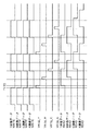
図6にページバッファメモリ306の書き込み動作と読み出し動作のタイミングチャートを示す一例を示す。図6のようにページバッファメモリ306の書き込み動作(「*画像データ WRITE」で記載:“*”はY/M/C/Kのいずれかの色を示す)は、各色成分が同時に入力され、書き込まれる。一方、読み出し動作は、図6のタイミングチャートのように、プリンタエンジン102より送信される各色成分に対応するビデオデータ要求信号が入力されたタイミングで対応する色成分のデータを読み出す。なお、図6において、読み出し動作は「*画像データ READ」(“*”はY/M/C/Kのいずれかの色を示す)で記載している。
FIG. 6 shows an example of a timing chart of the write operation and read operation of the
また、図6において、ビデオデータ要求信号は、各色成分に対し、VREQ_Y、VREQ_M、VREQ_C、VREQ_Kにて示している。これはプリンタエンジン102内の各色成分に対応する感光ドラム1401〜1404が配置された上流から下流までの距離に応じて、感光ドラム1401〜1404それぞれに露光するタイミングが異なるため、各色成分のデータの読み出すタイミングも異なる。従って、図6に示すタイミングT1においては、少なくともバッファした1ページの4色分のメモリ容量と次ページの4色分のメモリ容量を確保する必要がある。そのため、本実施形態においてページバッファメモリ306は、2ページ分のメモリ容量を備えているものとする。
In FIG. 6, the video data request signal is indicated by VREQ_Y, VREQ_M, VREQ_C, and VREQ_K for each color component. This is because the exposure timing of each of the
なお、本実施形態では、書き込み動作を行う書き込みクロックと読み出し動作を行う読み出しクロックを同じ周波数、つまり各色成分の1ページ分の書き込み時間と読み出し時間が等しいものとした。しかし、異なる場合にはその周波数比と上述した感光ドラム1401〜1404の配置距離に基づいてページバッファメモリ306の容量を確保しなければならない。
In this embodiment, the write clock for performing the write operation and the read clock for performing the read operation are set to have the same frequency, that is, the write time and read time for one page of each color component are equal. However, if they are different, the capacity of the
VREQ_*(“*”はY/M/C/Kのいずれか)に応答してページバッファメモリ306から順次出力された色成分データには、各色成分データの先頭にヘッダデータとしてカウンタキュー307に保持されていた各色成分のビデオデータが順次付加される。
The color component data sequentially output from the
[データフォーマット]
図7は、実際の色成分データと付加されたビデオカウントデータのデータフォーマットを示す図である。図7に示すページデータY701、ページデータM702、ページデータC703、ページデータK704はそれぞれ、イエロー、マゼンタ、シアン、ブラックのページデータの一例である。PageID705〜708は、各ページの番号を示すIDのフィールドであり、ビデオカウント生成部302にてページ順に付加される。PageID705〜708のフィールドは、例えば、6ビットから構成される。
[data format]
FIG. 7 is a diagram showing a data format of actual color component data and added video count data. The page data Y701, page data M702, page data C703, and page data K704 shown in FIG. 7 are examples of yellow, magenta, cyan, and black page data, respectively.
ComponentID709〜712は、ページデータの色成分がY、M、C、Kのいずれかであることを識別するためのIDのフィールドである。本実施形態であればY、M、C、Kにそれぞれ“00”、“01”、“10”、“11”を割り当てる2ビットのフィールドを持てばよい。0
Count*(*はY/M/C/Kのいずれか)713〜716は、カウンタキュー307に保持されていた各色成分のビデオカウントを付加するフィールドである。したがって、Count*713〜716のフィールドは、例えば、8ビット(0〜256)から構成される。*−PlaneData(*はY/M/C/Kのいずれか)717〜720は、実際の各色成分の画像データが格納されているフィールドである。
Count * (* is one of Y / M / C / K) 713 to 716 is a field to which a video count of each color component held in the
なお、データフォーマットの構成については、上記のビット数に限定するものではなく、扱う最大画像データのサイズ、ページ数、色数等に合わせて変更しても良い。 The configuration of the data format is not limited to the number of bits described above, and may be changed according to the size of the maximum image data to be handled, the number of pages, the number of colors, and the like.
[カウンタキューおよびビデオカウント生成部における動作]
次にカウンタキュー307およびビデオカウント生成部302の動作を説明する。図10はカウンタキュー307の内部構成図である。図10は色成分の1つであるイエローのカウンタキューの構成を示すが、カウンタキュー307内にはその他の色成分であるマゼンタ、シアン、ブラックのカウンタキューもそれぞれ備えているが構成はいずれも同様のものとする。図10のようにカウンタキューとして、4ワード長のFIFO(First−In First−Out)1001のメモリを備えている。つまり、FIFO1001には0〜3までのアドレスを有する。
[Operation in counter queue and video count generation unit]
Next, operations of the
以下、カウンタキュー307内のイエローのカウンタキューの動作を説明するが、その他のマゼンタ、シアン、ブラックも同様の動作である。図11はカウンタキュー307内のイエローのカウンタキュー動作を説明するタイミングチャートである。上述したビデオカウント生成部302から生成された色成分ごとのビデオカウントは、生成されたタイミング(図6に示すT1)で図11のイエローライトリクエストを“ON”にする。イエローライトリクエストの“ON”の信号を受信したライトアドレスポインタ1003は内部のアドレスポインタを1つインクリメントする。
The operation of the yellow counter queue in the
さらに、ライトアドレスポインタ1003は、FIFO1001に対してライト動作を許可するライトイネーブルを“ON”にし、そのライトアドレス値とライトイネーブル1008をインタフェース部1002へ出力する。そのタイミングでビデオカウント生成部302は、対応する色成分のビデオカウント(この場合はイエローカウント値)を、イエローカウント値入力1005を介してインタフェース部1002に入力する。インタフェース部1002は、ライトイネーブル1008とライトアドレスポインタ1003より入力されたライトアドレスに対応するFIFO1001のメモリ領域にイエローカウント値入力1005を介して入力されたイエローカウント値を格納する。
Further, the
ビデオカウント挿入部308は、前段のドラム間遅延メモリ制御部305より順次出力されてくるタイミング(図6に示すT2)で各色に対応するカウンタキュー307のリードリクエスト信号を“ON”にする。リードリクエスト信号の“ON”を受信したリードアドレスポインタ1004は内部のアドレスポインタを1つインクリメントする。さらにリードアドレスポインタ1004は、FIFO1001に対してリード動作を許可するリードイネーブルをONし、そのリードアドレス値とリードイネーブル1009をインタフェース部1002へ出力する。インタフェース部1002は、入力されたリードアドレスに対応するFIFO1001のメモリ領域に格納されている各色成分のカウント値(この場合イエローカウント値)を、イエローカウント値出力1006を介して出力する。
The video
なお、本実施形態では、FIFO1001は、4ワード長のアドレスを有し、計4ページ分のビデオカウントを保持できる構成とした。しかし、この構成に限定されるものではなく、書き込みタイミング、読み出しタイミングによってFIFO1001のワード長を決定しなければならない。
In the present embodiment, the
ビデオカウント挿入部308は、各色成分に対応するカウント値を、Count*(*はY/M/C/Kのいずれか)713〜716を所定のフィールドに付加する。併せて、ビデオカウント挿入部308は、PageID705〜718、ComponentID709〜712も付加する。これにより、図7で示したページデータ*(*はY/M/C/Kのいずれか)701〜704のページヘッダを構成する。
The video
このように生成されたページヘッダを、ビデオカウント挿入部308は、各色成分データを格納した*−PlaneData(*はY/M/C/Kのいずれか)717〜719のフィールドと結合する。そして、ビデオカウント挿入部308は、ページデータ*(*はY/M/C/Kのいずれか)701〜704としてプリンタエンジン102へ順次出力される。
The video
[プリンタエンジン動作]
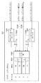
次にプリンタ画像処理部119より出力されたページヘッダが付加された色成分データがプリンタエンジン102に入力されたときの動作について説明する。図12はプリンタエンジン102の内部構成の一部を示す。プリンタI/F部1201は、プリンタ画像処理部119から順次送信されてくる色成分データを受信する。また、プリンタI/F部1201は、プリンタエンジン102において印字動作の準備が可能となった場合に各色成分のデータを要求するビデオデータ要求信号であるVREQ_*(*はY/M/C/Kのいずれか)を発行する。
[Printer engine operation]
Next, the operation when the color component data with the page header output from the printer
ビデオカウント抽出部1202は、上述したようにビデオカウント挿入部308にて付加された各色成分のCount*(*はY/M/C/Kのいずれか)713〜716をそれぞれ抽出する。そして、ビデオカウント抽出部1202は、抽出した値を対応する色成分の*トナー補給制御部(*はY/M/C/Kのいずれか)1204〜1207へそれぞれ送信する。
The video
各トナー補給制御部1204〜1207は受信したCount*の値に応じてトナー補給を行うための*トナー補給モータ(*はY/M/C/Kのいずれか)1208〜1211をそれぞれ駆動する。例えばイエローのビデオカウントであるCountY713の値が“100”である場合には、1secだけトナー補給モータを駆動させるようにYトナー補給制御部1204よりYトナー補給モータ1208に駆動信号を与えることで実現できる。
The toner
一方、色成分データはビデオカウント抽出部1202を経てパルス幅変調回路1203に入力される。そして、パルス幅変調回路1203は、実際の色成分データである*−PlaneData717〜720に基づいて、後段の各色の*レーザー駆動部1212〜1215を駆動させるためのパルス信号(駆動信号)を生成する。そして、パルス幅変調回路1203は、各レーザー駆動部1212〜1215へ送信する。
On the other hand, the color component data is input to the pulse
各色成分に対応した各レーザー駆動部1212〜1215はパルス幅変調回路1203より受信したパルス信号に基づいて各色成分に対応する後述のレーザー露光装置を駆動する。
Each
[レーザー駆動動作]
図13は実際の各色成分データの送信タイミングに基づく各レーザー駆動部1212〜1215のレーザー駆動のタイミングと、各トナー補給モータ1208〜1211への駆動のタイミングを示すタイミングチャートである。図13のようにプリンタエンジン102には、各色の色成分データである*−PlaneData717〜720と、トナー補給を行うCount*713〜716が付加されている。そのため、常に各色のレーザー駆動タイミングと対応するトナー補給動作を常に同期させることができる。なお、図13中のΔTy、ΔTm、ΔTc、ΔTkは対応する*−PlaneData717〜720のヘッダとして付加されたCount*713〜716に基づいて、“ON”にする信号の所要時間であるため色成分ごとに異なる。
[Laser drive operation]
FIG. 13 is a timing chart showing laser drive timings of the
[プリンタエンジン構造]
図14はプリンタエンジン102の作像部分の断面図である。以下、主にイエローの作像部分について説明するが、他の色成分のマゼンタ、シアン、ブラックの作像部分についても同様の構成である。なお、本実施形態においては、プリンタエンジン102として、YMCKの4色からなるタンデム式エンジンを用いた画像形成装置を対象としているが、本発明は2以上の色数を用いるタンデム式エンジンの画像形成装置であれば、適用可能である。例えば、CMYの3色からなるタンデム式エンジンを用いても構わないし、もしくはライトマゼンタ、ライトシアンの2色を加えた6色からなるタンデム式エンジンを用いても構わない。
[Printer engine structure]
FIG. 14 is a cross-sectional view of an image forming portion of the
プリンタエンジン102は、像担持体である感光ドラム1401、帯電ローラ1405、Yレーザー露光装置1406、Yトナー補給機構1407、1次転写装置1408、2次転写装置1413、定着装置1414、およびクリーニング装置1415を備える。Yレーザー露光装置1406は、Yレーザー駆動部1212より駆動される。Yトナー補給機構1407は、Yトナー補給制御部1204より駆動されるYトナー補給モータ1208に基づいて補給動作を制御する。1次転写装置1408は、可視化されたトナー像を転写材1412上に1次転写する。2次転写装置1413は、転写材1412上に形成されたトナー像を記録用紙に2次転写する。定着装置1414は、記録用紙上に転写されたトナー像を定着する。クリーニング装置1415は、2次転写後に転写材1412に残った転写残トナーを除去する。
The
現像装置1416は現像剤容器を備え、二成分現像剤としてトナー粒子(トナー)と磁性キャリア粒子(キャリア)とが混合された現像剤が収容されている。Aスクリュー1420とBスクリュー1421はそれぞれトナー粒子の搬送と磁性キャリア粒子との混合を行う。なお、Bスクリュー1421の上方にトナー補給機構1407が配置されており、各色のビデオカウントに基づいて算出されたトナー消費量に基づくトナー量がトナー補給機構1407より落下され補給される。また現像スリーブ1422は、感光ドラム1401に近接に配置され、感光ドラム1401と従動するように回転して、トナーとキャリアとが混合された現像剤を担持する。現像スリーブ1422に担持された現像剤は感光ドラム1401に接触し、感光ドラム1401上の静電潜像が現像される。なお、プリンタエンジン102には図14の構成以外にも印字用紙を搬送する搬送部(不図示)等があるが、本実施形態において、説明を省略する。
The developing
以上のようなプリンタエンジンの構成において、イエローを印字する場合には、Yレーザー駆動部1212より駆動されるYレーザー露光装置1406により感光ドラム1401に露光され、感光ドラム1401上に静電潜像を形成する。形成された静電潜像は、現像装置1416内の現像スリーブ1422上に担持されているイエローの現像剤によりトナー像として可視化され、可視化されたトナー像は転写材1412上に1次転写装置1408によって転写される。
In the configuration of the printer engine as described above, when printing yellow, the
このようにしてマゼンタ、シアン、ブラックの各色成分も同様に各現像装置1417、1418、1419により現像され、感光ドラム1402、1403、1404にそれぞれトナー像として可視化される。そして、可視化されたトナー像は直前に転写された色成分のトナー像と同期して、それぞれ1次転写装置1409、1410、1411により順次転写され、転写材1412上には4色のトナー像により形成された最終的なトナー画像が形成される。
In this way, the magenta, cyan, and black color components are similarly developed by the developing
転写材1412に形成されたトナー画像は、2次転写装置1413にて同期して搬送されてくる記録用紙に2次転写され、定着装置1414にてトナー像を定着される。そして、プリンタエンジン102により記録用紙が排出され、プリント動作を終了する。
The toner image formed on the
[トナー補給動作]
次に、本実施形態によるビデオカウントの生成と画像データの付加、およびそのビデオカウントに基づくトナー補給動作を図15のフローチャートに基づいて説明する。なお、本処理フローは、画像形成装置100が有するCPU105が、記憶部であるHDD108等に格納されたプログラムを読みだし、実行することにより実現される。
[Toner supply operation]
Next, generation of a video count, addition of image data, and toner supply operation based on the video count according to the present embodiment will be described based on the flowchart of FIG. This processing flow is realized by the
RIP部116にてレンダリングされ、展開された画像データは、画像圧縮部103にて圧縮され、HDD108に順次格納される。HDD108に格納された画像データは、画像伸張部121にてデータの伸長を行う。画像伸張部121で伸長された画像データは、デバイスI/F117を介してプリンタ画像処理部119へ転送される(S1501)。プリンタ画像処理部119へ転送された画像データが色空間変換部301にて色空間変換された後、ビデオカウント生成部302は各画素の色成分データ(この場合Y/M/C/K)の階調値(多値)の積算を行う(S1502)。
The image data rendered and expanded by the
1ページ分の階調値の積算が終了した後(S1503にてYES)、ビデオカウント生成部302は、図5に示したようなカウント変換LUT303を参照し、積算値からトナー補給に相関のあるビデオカウントを算出する(S1504)。続いて、画像データはページバッファメモリ306に順次格納される(S1505)。1ページ分の画像データが格納された後(S1506にてYES)、ドラム間遅延メモリ制御部305は、プリンタエンジン102からVREQ(ビデオデータ要求信号)を受信するまで待機する(S1507)。そして、VREQを受信した場合(S1507にてYES)、ドラム間遅延メモリ制御部305は、対応する色成分のVREQ_*(*はY/M/C/Kのいずれか)を判断する(S1508〜S1510)。対応する色成分のVREQ_*を受信したら、ビデオカウント挿入部308は、ページバッファメモリ306より対応する色成分データを順次読み出す。そして、ビデオカウント挿入部308は、カウンタキュー307に保持されていた各ビデオカウントを色成分データのヘッダデータとしてそれぞれ付加する(S1511〜S1514)。
After the accumulation of gradation values for one page is completed (YES in S1503), the video
プリンタエンジン102内のビデオカウント抽出部1202は、受信したデータから色成分ごとのビデオカウントを抽出し、色成分データに対応したレーザー露光のタイミングに同期して各色のトナー補給を実行する(S1515〜S1518)。ページバッファメモリ306から1ページ分の色成分データが読み出された後(S1519〜S1522のいずれかにてYES)、*レーザー駆動部1212〜1215により対応するレーザー露光、そして現像が行われる。そして、本処理フローを終了する。
The video
以上、画像データの画素に対するそれぞれの色成分データの値を積算し、トナー消費量に関連するビデオカウントに変換する。そして、実際にプリンタエンジンにて印字するデータのヘッダデータとして付加する。これにより、CPUを介在してビデオカウントを送信しトナー補給を行う場合よりも、実際の各色成分に対応したプリンタエンジンの現像タイミングと同期して、実際に使用するトナー量を補給することができる。 As described above, the values of the respective color component data for the pixels of the image data are integrated and converted into a video count related to the toner consumption. Then, it is added as header data of data actually printed by the printer engine. As a result, the amount of toner actually used can be replenished in synchronization with the development timing of the printer engine corresponding to each actual color component, compared with the case where the toner is replenished by transmitting a video count via the CPU. .
また、本実施形態により、色成分ごとに複数の感光ドラムを備えるタンデムエンジンにおいても、各色成分の現像タイミングのずれに対応して各色のトナー量を補給することができる。 Further, according to the present embodiment, even in a tandem engine including a plurality of photosensitive drums for each color component, the toner amount of each color can be replenished in response to a shift in development timing of each color component.
<第二実施形態>
第一実施形態では、ページ単位でビデオカウントを積算していた。本実施形態では、1ページの画像データを複数分割し、その分割した単位で色成分ごとにビデオカウントを付加する方法およびそれに基づくトナー補給制御について説明する。画像形成装置100、各ソフトウェアモジュールは第一実施形態と構成が同様であり、またプリンタ動作におけるプリンタ画像処理部119へ入力されるまでの処理フローは同様であるため説明を省略する。
<Second embodiment>
In the first embodiment, video counts are integrated in units of pages. In the present embodiment, a method of dividing a page of image data into a plurality of parts and adding a video count for each color component in the divided unit, and toner supply control based on the method will be described. The configuration of the
プリンタ動作において、同様にプリンタ画像処理部119へ入力された画像データは第一実施形態と同様に色空間変換部301で輝度値(本実施形態ではRGB)から濃度値(本実施形態ではCMYK)に変換する。CMYKデータ変換された画像データはビデオカウント生成部302にて各画素の色成分ごとの階調値(多値データ)を積算していく。本実施形態の場合、1ページを4つのバンドに分割したエリアをそれぞれカウントし、積算値として用いるものとする。
In the printer operation, similarly, the image data input to the printer
例えば、A4サイズ:600dpiの画像データの場合には、主走査方向:7015画素×副走査方向:4962画素のサイズを副走査方向に4等分する。このとき、主走査方向:7015画素×副走査方向:1241画素(4分割目の副走査方向のサイズは残りの1239画素)のサイズにて積算値を算出する。 For example, in the case of image data of A4 size: 600 dpi, the size of main scanning direction: 7015 pixels × sub-scanning direction: 4962 pixels is equally divided into four in the sub-scanning direction. At this time, the integrated value is calculated with a size of main scanning direction: 7015 pixels × sub-scanning direction: 1241 pixels (the size of the fourth division in the sub-scanning direction is the remaining 1239 pixels).
なお、本実施形態では1ページを副走査方向に4等分したサイズの各積算値を算出する例を示している。しかし、ビデオカウント生成部302にCPU105より設定できる設定バス(不図示)を介して、1ページの分割の方法、分割数を自由に設定することも可能である。また、印字する画像のサイズに応じて分割数を変更しても構わない。
In the present embodiment, an example is shown in which each integrated value having a size obtained by dividing one page into four equal parts in the sub-scanning direction is calculated. However, it is also possible to freely set the division method and the number of divisions for one page via a setting bus (not shown) that can be set by the
指定された分割サイズ分(本実施形態では、1ページの1/4サイズ)の積算値が終了した時点で随時カウントした積算値とカウント変換LUT303内に予め設定されている値とを比較してカウントした積算値からビデオカウントに変換する。このようにして1ページの任意の分割サイズでの各色成分に対応するビデオカウントは各々カウント変換LUT303を参照して求められる。次に算出された分割サイズごとのビデオカウントはカウンタキュー307へ入力され、一時的に保持される。
The integrated value counted at any time when the integrated value for the designated divided size (in this embodiment, 1/4 size of one page) is completed is compared with the value preset in the
ビデオカウント生成部302にてカウントされた多値の画像データは、第一実施形態と同様に中間調処理部304で中間調処理を行い、2値(1ビット)で表現される画像データへ変換される。中間調処理部304で処理された2値の画像データは、ドラム間遅延メモリ制御部305を介し、画像データ内の色成分ごとに分離されページバッファメモリ306に一時的に格納される。本実施形態においてもページバッファメモリ306の書き込み動作と読み出し動作のタイミングは図6と同様に行うものとする。
The multi-value image data counted by the video
VREQ_*(*はY/M/C/Kのいずれか)に対応して順次出力された色成分データは、ビデオカウント挿入部308にて、上述した分割エリアごとに各分割エリアの色成分ごとのビデオカウンタが所定のフィールドに付加される。
The color component data sequentially output corresponding to VREQ_ * (* is one of Y / M / C / K) is output by the video
[データフォーマット]
図8は、本実施形態における色成分データと分割エリアごとに付加されたビデオカウントデータのデータフォーマットを示す図である。図8のページデータY801、ページデータM802、ページデータC803、ページデータK804はそれぞれイエロー、マゼンタ、シアン、ブラックのページデータの一例である。以下、イエローのページデータY801について説明するが、マゼンタ、シアン、ブラックのページデータM802、ページデータC803、ページデータK804についても同様の構成を有する。
[data format]
FIG. 8 is a diagram showing the data format of the color component data and video count data added for each divided area in the present embodiment. The page data Y801, page data M802, page data C803, and page data K804 in FIG. 8 are examples of yellow, magenta, cyan, and black page data, respectively. Hereinafter, the yellow page data Y801 will be described, but the magenta, cyan, and black page data M802, page data C803, and page data K804 have the same configuration.
PageID805と、ComponentID806は、第一実施形態にて示した図7と同様に、各ページの番号を示すIDとページデータの色成分を識別するIDである。PageBandNum807は、1ページの分割数を表すフィールドであり、本実施形態では4分割を示す“4”が格納される。なお、このフィールドのビット数は、分割可能な数に応じて定義する。
BandLength0〜3(808〜811)は、PageBandNum807で表された分割数に基づいて分割されたエリアの副走査方向の長さを示すフィールドである。本構成では副走査方向に4分割するようにフィールドを定義した。つまり、BandLengthは4つのフィールドを有することとなる。また、上述した1ページがA4サイズ:600dpiの画像データを副走査方向に4等分する場合、A4サイズの1ページは主走査方向:7015画素×副走査方向:4962画素からなる。そのため、BandLength0〜3(808〜811)の4つのフィールドそれぞれに1241、1241、1241、1239の値を入れることにより副走査方向にほぼ4等分できるように設定することで実現できる。また本実施形態では、4分割するのでBandLength0〜3に全て値を格納したが、分割数がそれ以下の場合には対応するBandLength0〜2のどれかに値を格納するだけでよい。また、分割可能な最大数がより多い場合には、それに応じたフィールド数を有することとなる。
なお、本実施形態においてはCountY0〜CountY3(812〜815)のように1ページを複数の分割エリアに分けてビデオカウントを設定できるフィールドを設けている。これは後述するカウンタキュー307に保持されていた各色成分のビデオカウントを付加するフィールドである。また、Y−PlaneData0〜3(816〜819)も分割エリアに対応した実際の各色成分の画像データが格納されているフィールドである。
In this embodiment, a field for setting a video count is provided by dividing one page into a plurality of divided areas, such as CountY0 to CountY3 (812 to 815). This is a field to which a video count of each color component held in a
[カウンタキューおよびビデオカウント挿入部における動作]
次に本実施形態のカウンタキュー307とビデオカウント挿入部308の動作を説明する。図16は本実施形態におけるカウンタキュー307の内部構成図である。図16は色成分の1つであるイエローのカウンタキューの構成を示す。プリンタ画像処理部119は、その他の色成分であるマゼンタ、シアン、ブラックのカウンタキューも備えているが構成は同様のものとする。図16のように本実施形態ではカウンタキューとして16ワード長のFIFO(First−In First−Out)1601のメモリを備えており、その他の構成は第一実施形態と同様である。
[Operation in counter queue and video count insertion section]
Next, operations of the
第一実施形態で説明した図11のタイミングチャートと同様に、ライトリクエスト信号に同期してライトアドレスポインタ1003をインクリメントし、FIFO1601の所定のアドレス領域にビデオカウントを格納していく。本実施形態では1ページを4分割し、1ページあたり各色で4つのビデオカウントを算出する。そのため、1ページでライトリクエスト信号は4回“ON”となり、各色で1ページあたり4つのアドレスを占有する。なお、本実施形態のようにFIFO1601は16ワード長のアドレスを有し、1ページ分を4分割した場合に計4ページ分のビデオカウントを保持できる構成とした。本実施形態では、1ページを4分割し、16のアドレス(4ページ×4分割分)を有しているが、これに限定するものではなく、例えば、分割数に応じて、アドレスの数を変更しても良い。
Similar to the timing chart of FIG. 11 described in the first embodiment, the
ビデオカウント挿入部308は、前段のドラム間遅延メモリ制御部305より順次出力されてくる画像データを受信する。予めバス(不図示)を介して、CPU105により設定された分割エリア設定値に基づいた色成分データを受信した時点で、順次リードリクエスト信号をカウンタキュー307へ送信する。リードリクエスト信号に同期してリードアドレスポインタ1004がインクリメントされ、同時にリードイネーブル1009を“ON”する。そして、リードアドレス値に基づくアドレスに格納されているビデオカウント値をインタフェース部1002とイエローカウント値出力1006上に出力する。本実施形態では1ページを4分割し、1ページあたり各色で4つのビデオカウントを保持しているため、1ページを処理する間に4回リードアクセス信号を“ON”とし、各分割エリアのビデオカウントを出力する。
The video
ビデオカウント挿入部308は、各色成分に対応するカウント値を付加していく。ページデータY801の場合、PageID805、ComponentID806、PageBandNum807、BandLength0〜3(808〜811)を所定のフィールドに付加した後、CountY0(812)を挿入する。そして、1番目の分割エリアの画像データであるY−PlaneData0を受信した後に、CountY1(813)を挿入する。このように、画像データの間に分割エリアごとのビデオカウントを挿入していき、ページデータY801としてプリンタエンジン102へ送信する。これにより、ビデオカウント挿入部308は、図8で説明したページデータ*(*はY/M/C/Kのいずれか)801〜804を構成する。同様にページデータM802、ページデータC803、ページデータK804も順次送信されていく。
The video
[プリンタエンジン動作]
次にプリンタ画像処理部119より出力されたページヘッダが付加された色成分データがプリンタエンジン102に入力されたときの動作について説明する。プリンタエンジン102の構成は、第一実施形態にて示した図12および図14と同様であるために説明を省略する。
[Printer engine operation]
Next, the operation when the color component data with the page header output from the printer
図17は、本実施形態に係るY/M/C/Kの色成分データの送信タイミングに基づく各レーザー駆動部のレーザー駆動のタイミングと、各トナー補給制御部のトナー補給モータへの駆動のタイミングとを示すタイミングチャートである。 FIG. 17 shows the timing of laser drive of each laser drive unit based on the transmission timing of Y / M / C / K color component data according to this embodiment, and the drive timing of each toner supply control unit to the toner supply motor. It is a timing chart which shows.
図17のようにプリンタエンジン102には、各色、各分割エリアの色成分データである*−PlaneData0〜3(*はY/M/C/Kのいずれか)と、トナー補給を行うCount*0〜3(*はY/M/C/Kのいずれか)とが付加されている。そのため、各色の1ページを4分割されたタイミングでトナー補給を駆動するΔTy0〜ΔTy3、ΔTm0〜ΔTm3、ΔTc0〜ΔTc3、ΔTk0〜ΔTk3のタイミングで“ON”にする。よって、常に各色のレーザー駆動タイミングと対応するトナー補給動作を常に同期させることができ、かつ1ページ中に4回のトナー補給制御を行うことで1ページ中に1回のトナー補給制御を行うよりも精度を向上させることが可能となる。
As shown in FIG. 17, the
[トナー補給動作]
次に、本実施形態によるビデオカウントの生成と画像データの付加、およびそのビデオカウントに基づくトナー補給動作を図19のフローチャートに基づいて説明する。なお、本処理フローは、画像形成装置100が有するCPU105が、記憶部であるHDD108等に格納されたプログラムを読みだし、実行することにより実現される。
[Toner supply operation]
Next, generation of a video count, addition of image data, and toner supply operation based on the video count according to the present embodiment will be described with reference to the flowchart of FIG. This processing flow is realized by the
S1501〜S1510は第一実施形態と同様である。対応する色成分のVREQ_*を受信すると、ドラム間遅延メモリ制御部305は、ページバッファメモリ306より対応する色成分データを順次読み出す。ここで上述したように、ドラム間遅延メモリ制御部305は、PageBandNum807で指定した分割数に基づき、各分割エリアを表すBandLength0〜3(808〜811)の色成分データを順次取得する。まず、BandLength0に指定した副走査方向におけるライン分のデータをビデオカウント挿入部308にて受信すると(S1911〜1914にてYES)、ビデオカウント挿入部308は、対応するビデオカウント(この場合、Count*0(812))を色成分データの所定のフィールドにそれぞれ付加する。(S1915〜S1918)。
S1501 to S1510 are the same as in the first embodiment. When the corresponding color component VREQ_ * is received, the inter-drum delay
その後、プリンタエンジン102内のビデオカウント抽出部1202は、色成分ごとのビデオカウントを抽出する。そして、*トナー補給制御部1204〜1207はそれぞれ色成分データからレーザー露光のタイミングに同期して各色のトナー補給を実行する(S1919〜S1922)。ビデオカウント挿入部308によるビデオカウントの付加から、*トナー補給制御部1204〜1207によるトナー補給動作までをそれぞれPageBandNum807で指定した分割数に応じて、色ごとに複数回処理を繰り返す。そして、ページバッファメモリ306から1ページ分の色成分データが読み出された後(S1923〜S1926)、各レーザー駆動部1212〜1215により対応するレーザー露光、および現像が行われて処理が終了する。
Thereafter, the video
以上、上述したように、例えば1ページを複数の領域に分割し、ページの分割エリアごとにビデオカウントを付加する構成にする。これにより、タンデムエンジンにおける各色成分の現像タイミングのずれに対応するだけでなく、さらに1ページ中の複数回のトナー補給制御を行うことが可能となる。 As described above, for example, one page is divided into a plurality of areas, and a video count is added to each divided area of the page. As a result, it is possible not only to cope with a shift in development timing of each color component in the tandem engine, but also to perform toner replenishment control a plurality of times in one page.
よって、本実施形態により、第一実施形態の効果に加え、トナー補給精度の向上が高まるだけではなく、例えば長尺紙のような副走査方向の長いサイズの印字においても1ページ中に複数回のトナー補給制御により安定した濃度で印字が可能となる。 Therefore, this embodiment not only improves the toner replenishment accuracy in addition to the effects of the first embodiment, but also multiple times in one page even in long size printing in the sub-scanning direction such as long paper. With this toner replenishment control, printing can be performed with a stable density.
<第三実施形態>
第一実施形態では、データフォーマットのヘッダにビデオカウント等の情報を付加していた。これに対し、本実施形態では、色成分ごとにビデオカウントをフッタとして付加する方法およびそれに基づくトナー補給制御について説明する。
<Third embodiment>
In the first embodiment, information such as video count is added to the header of the data format. In contrast, in this embodiment, a method of adding a video count as a footer for each color component and toner supply control based thereon will be described.
画像形成装置100、および各ソフトウェアモジュールは第一実施形態と構成が同様であり、またプリンタ動作におけるプリンタ画像処理部119へ入力されるまでの処理フローは同様であるため説明を省略する。
The configuration of the
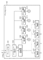
図4は本実施形態のプリンタ画像処理部119を示す内部構成図である。本実施形態では中間調処理部304の後段にビデオカウント挿入部401を設ける構成とした。そして、ビデオカウント挿入部401の後段にドラム間遅延メモリ制御部305が配置される。また、本実施形態において、カウンタキュー307は含まれず、ビデオカウント生成部302から、ビデオカウント挿入部401へビデオカウントが直接入力される構成となっている。
FIG. 4 is an internal configuration diagram showing the printer
プリンタ動作において、同様にプリンタ画像処理部119へ入力された画像データは第一実施形態と同様に色空間変換部301で輝度値(本実施の形態ではRGB)から濃度値(本実施の形態ではCMYK)に変換する。CMYKデータに変換された画像データはビデオカウント生成部302にて各画素の色成分ごとの階調値(多値データ)を積算していく。第一実施形態と同様に、1ページ分をカウントし、積算値として用いるものとする。
In the printer operation, similarly, the image data input to the printer
ビデオカウント生成部302にて求められた積算値はカウント変換LUT303を用いて1ページ分の各色成分のビデオカウントに変換され、後段のビデオカウント挿入部401に即座に送信される。また、ビデオカウント生成部302にてカウントされた多値の画像データは、第一実施形態と同様に中間調処理部304で中間調処理を行い、2値(1ビット)で表現される画像データへ変換される。ここで、本実施形態においては、ビデオカウント挿入部401は、中間調処理部304にて各色成分2値(1ビット)で表現される画像データのフッタとして、ビデオカウントを挿入する。
The integrated value obtained by the video
[データフォーマット]
図9は、本実施形態における色成分データとフッタとして付加されたビデオカウントデータのデータフォーマットを示す。図9のように、第一実施形態のデータフォーマットに対して、Count*(*はY/M/C/Kのいずれか)913〜916は、各色成分データである*−PlaneData917〜920の後にフッタとしてそれぞれ付加される。
[data format]
FIG. 9 shows a data format of color component data and video count data added as a footer in this embodiment. As shown in FIG. 9, with respect to the data format of the first embodiment, Count * (* is one of Y / M / C / K) 913 to 916 is after each color component data * -
[トナー補給動作]
図18は本実施形態に係る各色成分データの送信タイミングに基づくレーザー駆動部1212〜1215のレーザー駆動タイミングと、各トナー補給モータ1208〜1211への駆動タイミングを示すタイミングチャートである。図18のようにページバッファメモリ306より色成分ごとに順次Y/M/C/Kに対応するレーザー駆動が“ON”にされ、レーザー露光した直後に各色に対応するトナー補給動作をそれぞれ実行する。つまり、図18に示す、ΔTy、ΔTm、ΔTc、ΔTkにタイミングで、各色のトナー補給制御が“ON”とされる。
[Toner supply operation]
FIG. 18 is a timing chart showing the laser drive timings of the
次に、本実施形態によるビデオカウントの生成と画像データの付加、およびそのビデオカウントに基づくトナー補給動作を図20のフローチャートに基づいて説明する。なお、本処理フローは、画像形成装置100が有するCPU105が、記憶部であるHDD108等に格納されたプログラムを読みだし、実行することにより実現される。
Next, generation of a video count, addition of image data, and toner supply operation based on the video count according to the present embodiment will be described with reference to the flowchart of FIG. This processing flow is realized by the
S1501〜S1504は第一実施形態と同様に1ページ分の積算が終了した後、ビデオカウント生成部302がカウント変換LUT303を参照し、積算値からトナー補給に相関のあるビデオカウントに変換する。中間調処理部304が画像データを各色成分データの2値データに展開した後、ビデオカウント生成部302により算出されたビデオカウントはビデオカウント挿入部401に直接送信される。そして、ビデオカウント挿入部401は、ビデオカウントを各色成分データのフッタとしてCount*913〜916のそれぞれのフィールドに同時に付加する(S2001)。
In S1501 to S1504, after the integration for one page is completed as in the first embodiment, the video
その後、第一実施形態と同様に、画像データはページバッファメモリ306に順次格納される。そして、1ページ分の画像データを格納した後(S1506にてYES)、ドラム間遅延メモリ制御部305は、プリンタエンジン102からVREQ_*(ビデオデータ要求信号)が受信されるまで待機する。VREQ_*を受信した場合(S1507にてYES)、ドラム間遅延メモリ制御部305は、対応する色成分のVREQ_*(*はY/M/C/Kのいずれか)を判断する(S1508〜S1510)。受信した各色成分のVREQ_*に応じて、ドラム間遅延メモリ制御部305は、ページバッファメモリ306より対応する色成分データを順次読み出し、プリンタエンジン102へと送信する。そして、プリンタエンジン102内のビデオカウント抽出部1202は、受信したデータから色成分ごとのビデオカウントを抽出する。そして、各トナー補給制御部1204〜1207はそれぞれ色成分データからレーザー露光のタイミングに同期して各色のトナー補給を実行する(S1515〜S1518)。ページバッファメモリ306から1ページ分の色成分データが読み出された後(S1519〜S1522のいずれかにてYES)、各レーザー駆動部1212〜1215による対応するレーザー露光、および現像が行われる。そして、本処理フローが終了する。
Thereafter, the image data is sequentially stored in the
以上、説明してきたように本実施形態は、各色のビデオカウントを各色の色成分データのフッタとして挿入する。これにより、第一実施形態の効果に加え、画像データからビデオカウントを算出した直後に、任意のタイミングでビデオカウントを挿入することができる。そのため、ページバッファメモリから画像データの出力タイミングに合わせてビデオカウントの読み出しを行うカウンタキューのような回路が必要ない。そのため、回路構成を単純化することが可能となる。 As described above, in the present embodiment, the video count of each color is inserted as a footer of the color component data of each color. Thereby, in addition to the effect of the first embodiment, the video count can be inserted at an arbitrary timing immediately after the video count is calculated from the image data. Therefore, there is no need for a circuit such as a counter queue that reads out the video count in accordance with the output timing of image data from the page buffer memory. Therefore, the circuit configuration can be simplified.
<その他の実施形態>
また、本発明は、以下の処理を実行することによっても実現される。即ち、上述した実施形態の機能を実現するソフトウェア(プログラム)を、ネットワーク又は各種記憶媒体を介してシステム或いは装置に供給し、そのシステム或いは装置のコンピュータ(またはCPUやMPU等)がプログラムを読み出して実行する処理である。
<Other embodiments>
The present invention can also be realized by executing the following processing. That is, software (program) that realizes the functions of the above-described embodiments is supplied to a system or apparatus via a network or various storage media, and a computer (or CPU, MPU, or the like) of the system or apparatus reads the program. It is a process to be executed.
Claims (11)
画像データの所定の範囲に含まれる各画素が有する各色成分の値を色成分毎に積算し、当該積算した値を各色成分のカウント値に変換する変換手段と、
前記変換手段にて変換された各色成分のカウント値のうち第1の色成分のカウント値を、前記画像データの前記第1の色成分のデータに付加し、前記各色成分のカウント値のうち第2の色成分のカウント値を、前記画像データの前記第2の色成分のデータに付加する付加手段と、
前記第1の色成分のデータと前記第2の色成分のデータに基づき画像形成を行う際、前記付加手段にて付加された各色成分のカウント値に応じて、色成分ごとの現像装置にトナーを補給する制御手段と
を有することを特徴とする画像形成装置。 An image forming apparatus having a developing device corresponding to a color component,
Conversion means for integrating each color component value of each pixel included in a predetermined range of image data for each color component, and converting the integrated value into a count value of each color component;
The count value of the first color component among the count values of each color component converted by the conversion means is added to the data of the first color component of the image data, and the first of the count values of the color components. Adding means for adding the count value of the second color component to the data of the second color component of the image data ;
When image formation is performed based on the data of the first color component and the data of the second color component , the toner is supplied to the developing device for each color component according to the count value of each color component added by the adding unit. And an image forming apparatus.
前記付加手段は、前記現像装置により現像を実行するタイミングに同期して、前記保持手段から順次出力される前記画像データの各色成分の値に、ヘッダとして、前記変換手段により変換された各色成分に対応する前記カウント値を付加することを特徴とする請求項1乃至3のいずれか一項に記載の画像形成装置。 Further comprising holding means for holding the value of each color component of each pixel included in the image data;
The adding unit synchronizes with each color component value of the image data sequentially output from the holding unit in synchronization with the timing of executing development by the developing device, and each color component converted by the converting unit as a header. The image forming apparatus according to claim 1, wherein the corresponding count value is added.
前記付加手段は、前記画像データの各色成分の値に、ヘッダとして、前記カウント値を付加する際に、前記記憶手段から取得して付加することを特徴とする請求項4に記載の画像形成装置。 Further comprising storage means for storing the count value converted by the conversion means;
5. The image forming apparatus according to claim 4, wherein the adding unit acquires and adds the count value as a header to the value of each color component of the image data from the storage unit. .
イエロー、マゼンタ、およびシアン、または、
イエロー、マゼンタ、シアン、およびブラック、または、
イエロー、マゼンタ、シアン、ブラック、ライトマゼンタ、およびライトシアン
の色成分それぞれに対応するエンジンを有するタンデム式エンジンを構成することを特徴とする請求項1乃至8のいずれか一項に記載の画像形成装置。 The developing device includes:
Yellow, magenta and cyan, or
Yellow, magenta, cyan, and black, or
9. The image forming apparatus according to claim 1, wherein the image forming apparatus includes a tandem engine having engines corresponding to color components of yellow, magenta, cyan, black, light magenta, and light cyan. .
変換手段が、画像データの所定の範囲に含まれる各画素が有する各色成分の値を色成分毎に積算し、当該積算した値を各色成分のカウント値に変換する変換工程と、
付加手段が、前記変換工程にて変換された各色成分のカウント値のうち第1の色成分のカウント値を、前記画像データの前記第1の色成分のデータに付加し、前記各色成分のカウント値のうち第2の色成分のカウント値を、前記画像データの前記第2の色成分のデータに付加する付加工程と、
制御手段が、前記第1の色成分のデータと前記第2の色成分のデータに基づき画像形成を行う際、前記付加工程にて付加された各色成分のカウント値に応じて、色成分ごとの現像装置にトナーを補給する制御工程と
を有することを特徴とする制御方法。 A control method of an image forming apparatus having a developing device corresponding to a color component,
A conversion step in which the conversion unit integrates the value of each color component of each pixel included in the predetermined range of the image data for each color component, and converts the integrated value into a count value of each color component;
The adding means adds the count value of the first color component among the count values of each color component converted in the conversion step to the data of the first color component of the image data, and counts the color components. An adding step of adding the count value of the second color component of the values to the data of the second color component of the image data ;
When the control unit performs image formation based on the data of the first color component and the data of the second color component , according to the count value of each color component added in the adding step, And a control step of supplying toner to the developing device.
画像データの所定の範囲に含まれる各画素が有する各色成分の値を色成分毎に積算し、当該積算した値を各色成分のカウント値に変換する変換手段、
前記変換手段にて変換された各色成分のカウント値のうち第1の色成分のカウント値を、前記画像データの前記第1の色成分のデータに付加し、前記各色成分のカウント値のうち第2の色成分のカウント値を、前記画像データの前記第2の色成分のデータに付加する付加手段、
前記第1の色成分のデータと前記第2の色成分のデータに基づき画像形成を行う際、前記付加手段にて付加された各色成分のカウント値に応じて、色成分ごとの現像装置にトナーを補給する制御手段
として機能させるためのプログラム。 Computer
Conversion means for integrating each color component value of each pixel included in a predetermined range of image data for each color component, and converting the integrated value into a count value of each color component;
The count value of the first color component among the count values of each color component converted by the conversion means is added to the data of the first color component of the image data, and the first of the count values of the color components. Adding means for adding the count value of the second color component to the data of the second color component of the image data;
When image formation is performed based on the data of the first color component and the data of the second color component , the toner is supplied to the developing device for each color component according to the count value of each color component added by the adding unit. For functioning as a control means for replenishing water.
Priority Applications (2)
| Application Number | Priority Date | Filing Date | Title |
|---|---|---|---|
| JP2010273943A JP5751814B2 (en) | 2010-12-08 | 2010-12-08 | Image forming apparatus, control method, and program |
| US13/296,351 US8699895B2 (en) | 2010-12-08 | 2011-11-15 | Image forming apparatus, control method and computer-readable medium |
Applications Claiming Priority (1)
| Application Number | Priority Date | Filing Date | Title |
|---|---|---|---|
| JP2010273943A JP5751814B2 (en) | 2010-12-08 | 2010-12-08 | Image forming apparatus, control method, and program |
Publications (3)
| Publication Number | Publication Date |
|---|---|
| JP2012123201A JP2012123201A (en) | 2012-06-28 |
| JP2012123201A5 JP2012123201A5 (en) | 2014-01-23 |
| JP5751814B2 true JP5751814B2 (en) | 2015-07-22 |
Family
ID=46199503
Family Applications (1)
| Application Number | Title | Priority Date | Filing Date |
|---|---|---|---|
| JP2010273943A Expired - Fee Related JP5751814B2 (en) | 2010-12-08 | 2010-12-08 | Image forming apparatus, control method, and program |
Country Status (2)
| Country | Link |
|---|---|
| US (1) | US8699895B2 (en) |
| JP (1) | JP5751814B2 (en) |
Families Citing this family (4)
| Publication number | Priority date | Publication date | Assignee | Title |
|---|---|---|---|---|
| JP5637870B2 (en) * | 2011-01-12 | 2014-12-10 | キヤノン株式会社 | Image forming apparatus |
| JP5691603B2 (en) * | 2011-02-16 | 2015-04-01 | 富士ゼロックス株式会社 | Image processing apparatus and program |
| JP6817785B2 (en) * | 2016-11-02 | 2021-01-20 | キヤノン株式会社 | Image forming device, control method and program |
| CN108966346B (en) * | 2017-05-17 | 2021-03-05 | 电信科学技术研究院 | Paging parameter configuration method and access network entity |
Family Cites Families (7)
| Publication number | Priority date | Publication date | Assignee | Title |
|---|---|---|---|---|
| JP3004123B2 (en) | 1992-05-18 | 2000-01-31 | キヤノン株式会社 | Developing device |
| JP2004282200A (en) * | 2003-03-13 | 2004-10-07 | Konica Minolta Holdings Inc | Image forming apparatus |
| JP2005099750A (en) * | 2003-08-28 | 2005-04-14 | Canon Inc | Image forming apparatus, and control system, cartridge and memory medium for image forming apparatus |
| JP4218951B2 (en) * | 2003-09-19 | 2009-02-04 | キヤノン株式会社 | Image forming apparatus, control method, and control program |
| JP5042912B2 (en) * | 2008-04-30 | 2012-10-03 | 株式会社リコー | Image forming apparatus and image forming method |
| JP4952706B2 (en) * | 2008-12-12 | 2012-06-13 | コニカミノルタビジネステクノロジーズ株式会社 | Image forming apparatus and toner supply method |
| JP2010217714A (en) * | 2009-03-18 | 2010-09-30 | Fuji Xerox Co Ltd | Image forming apparatus |
-
2010
- 2010-12-08 JP JP2010273943A patent/JP5751814B2/en not_active Expired - Fee Related
-
2011
- 2011-11-15 US US13/296,351 patent/US8699895B2/en not_active Expired - Fee Related
Also Published As
| Publication number | Publication date |
|---|---|
| US20120148270A1 (en) | 2012-06-14 |
| US8699895B2 (en) | 2014-04-15 |
| JP2012123201A (en) | 2012-06-28 |
Similar Documents
| Publication | Publication Date | Title |
|---|---|---|
| EP1974927B1 (en) | Image formation system, image formation device, and control method thereof | |
| US7593131B2 (en) | Image forming apparatus in which reading of image data stored in a delay memory is controlled based on pixel counts of a page stored in a length holding unit | |
| US7636176B2 (en) | Image forming apparatus, method and storage medium | |
| US7701610B2 (en) | Image processing apparatus capable of printing with substitute recording agent and image processing method | |
| JP5751814B2 (en) | Image forming apparatus, control method, and program | |
| JP4323742B2 (en) | Image processing apparatus, image processing apparatus control method, and program | |
| JP4115294B2 (en) | Image processing apparatus and method | |
| US7920288B2 (en) | Image forming apparatus, image forming method and program | |
| JP5419608B2 (en) | Image forming apparatus and image forming method | |
| JP2005111852A (en) | Imaging device, printing control method and program | |
| JP5038272B2 (en) | Image processing apparatus, image processing method, and program | |
| JP2004094731A (en) | Image forming apparatus and its method | |
| JP7256660B2 (en) | IMAGE FORMING APPARATUS, CONTROL METHOD THEREOF, AND PROGRAM | |
| JP2006171940A (en) | Printing system | |
| JP2004255610A (en) | Control method of image formation apparatus | |
| JP4956677B2 (en) | Image forming apparatus and image forming method | |
| JP2006245920A (en) | Image forming device and image processing method | |
| JP2005027037A (en) | Format conversion method and image processing apparatus | |
| JP2022052350A (en) | Image forming apparatus, method for controlling image forming apparatus, and program | |
| JP2007036340A (en) | Tandem color printer, and data compression and expansion method | |
| JP2005277538A (en) | Image processing apparatus, program, and storage medium | |
| JP2017161672A (en) | Image forming apparatus | |
| JP2005144788A (en) | Image forming apparatus | |
| JP2006159481A (en) | Print system | |
| JP2006080914A (en) | Image processor, image processing method and program to be performed by computer |
Legal Events
| Date | Code | Title | Description |
|---|---|---|---|
| A521 | Request for written amendment filed |
Free format text: JAPANESE INTERMEDIATE CODE: A523 Effective date: 20131203 |
|
| A621 | Written request for application examination |
Free format text: JAPANESE INTERMEDIATE CODE: A621 Effective date: 20131203 |
|
| A977 | Report on retrieval |
Free format text: JAPANESE INTERMEDIATE CODE: A971007 Effective date: 20140925 |
|
| A131 | Notification of reasons for refusal |
Free format text: JAPANESE INTERMEDIATE CODE: A131 Effective date: 20140929 |
|
| A521 | Request for written amendment filed |
Free format text: JAPANESE INTERMEDIATE CODE: A523 Effective date: 20141128 |
|
| TRDD | Decision of grant or rejection written | ||
| A01 | Written decision to grant a patent or to grant a registration (utility model) |
Free format text: JAPANESE INTERMEDIATE CODE: A01 Effective date: 20150420 |
|
| A61 | First payment of annual fees (during grant procedure) |
Free format text: JAPANESE INTERMEDIATE CODE: A61 Effective date: 20150519 |
|
| LAPS | Cancellation because of no payment of annual fees |