KR20180098135A - Chain guide - Google Patents
Chain guide Download PDFInfo
- Publication number
- KR20180098135A KR20180098135A KR1020180016268A KR20180016268A KR20180098135A KR 20180098135 A KR20180098135 A KR 20180098135A KR 1020180016268 A KR1020180016268 A KR 1020180016268A KR 20180016268 A KR20180016268 A KR 20180016268A KR 20180098135 A KR20180098135 A KR 20180098135A
- Authority
- KR
- South Korea
- Prior art keywords
- rib
- guide
- chain
- main body
- support wall
- Prior art date
- Legal status (The legal status is an assumption and is not a legal conclusion. Google has not performed a legal analysis and makes no representation as to the accuracy of the status listed.)
- Granted
Links
Images

Classifications
-
- F—MECHANICAL ENGINEERING; LIGHTING; HEATING; WEAPONS; BLASTING
- F16—ENGINEERING ELEMENTS AND UNITS; GENERAL MEASURES FOR PRODUCING AND MAINTAINING EFFECTIVE FUNCTIONING OF MACHINES OR INSTALLATIONS; THERMAL INSULATION IN GENERAL
- F16H—GEARING
- F16H7/00—Gearings for conveying rotary motion by endless flexible members
- F16H7/18—Means for guiding or supporting belts, ropes, or chains
-
- F—MECHANICAL ENGINEERING; LIGHTING; HEATING; WEAPONS; BLASTING
- F16—ENGINEERING ELEMENTS AND UNITS; GENERAL MEASURES FOR PRODUCING AND MAINTAINING EFFECTIVE FUNCTIONING OF MACHINES OR INSTALLATIONS; THERMAL INSULATION IN GENERAL
- F16H—GEARING
- F16H7/00—Gearings for conveying rotary motion by endless flexible members
- F16H7/08—Means for varying tension of belts, ropes or chains
-
- F—MECHANICAL ENGINEERING; LIGHTING; HEATING; WEAPONS; BLASTING
- F02—COMBUSTION ENGINES; HOT-GAS OR COMBUSTION-PRODUCT ENGINE PLANTS
- F02B—INTERNAL-COMBUSTION PISTON ENGINES; COMBUSTION ENGINES IN GENERAL
- F02B67/00—Engines characterised by the arrangement of auxiliary apparatus not being otherwise provided for, e.g. the apparatus having different functions; Driving auxiliary apparatus from engines, not otherwise provided for
- F02B67/04—Engines characterised by the arrangement of auxiliary apparatus not being otherwise provided for, e.g. the apparatus having different functions; Driving auxiliary apparatus from engines, not otherwise provided for of mechanically-driven auxiliary apparatus
- F02B67/06—Engines characterised by the arrangement of auxiliary apparatus not being otherwise provided for, e.g. the apparatus having different functions; Driving auxiliary apparatus from engines, not otherwise provided for of mechanically-driven auxiliary apparatus driven by means of chains, belts, or like endless members
-
- F—MECHANICAL ENGINEERING; LIGHTING; HEATING; WEAPONS; BLASTING
- F16—ENGINEERING ELEMENTS AND UNITS; GENERAL MEASURES FOR PRODUCING AND MAINTAINING EFFECTIVE FUNCTIONING OF MACHINES OR INSTALLATIONS; THERMAL INSULATION IN GENERAL
- F16H—GEARING
- F16H7/00—Gearings for conveying rotary motion by endless flexible members
- F16H7/08—Means for varying tension of belts, ropes or chains
- F16H2007/0863—Finally actuated members, e.g. constructional details thereof
- F16H2007/0872—Sliding members
-
- F—MECHANICAL ENGINEERING; LIGHTING; HEATING; WEAPONS; BLASTING
- F16—ENGINEERING ELEMENTS AND UNITS; GENERAL MEASURES FOR PRODUCING AND MAINTAINING EFFECTIVE FUNCTIONING OF MACHINES OR INSTALLATIONS; THERMAL INSULATION IN GENERAL
- F16H—GEARING
- F16H7/00—Gearings for conveying rotary motion by endless flexible members
- F16H7/08—Means for varying tension of belts, ropes or chains
- F16H2007/0889—Path of movement of the finally actuated member
- F16H2007/0893—Circular path
-
- F—MECHANICAL ENGINEERING; LIGHTING; HEATING; WEAPONS; BLASTING
- F16—ENGINEERING ELEMENTS AND UNITS; GENERAL MEASURES FOR PRODUCING AND MAINTAINING EFFECTIVE FUNCTIONING OF MACHINES OR INSTALLATIONS; THERMAL INSULATION IN GENERAL
- F16H—GEARING
- F16H7/00—Gearings for conveying rotary motion by endless flexible members
- F16H7/18—Means for guiding or supporting belts, ropes, or chains
- F16H2007/185—Means for guiding or supporting belts, ropes, or chains the guiding surface in contact with the belt, rope or chain having particular shapes, structures or materials
Landscapes
- Engineering & Computer Science (AREA)
- General Engineering & Computer Science (AREA)
- Mechanical Engineering (AREA)
- Chemical & Material Sciences (AREA)
- Combustion & Propulsion (AREA)
- Devices For Conveying Motion By Means Of Endless Flexible Members (AREA)
Abstract
[과제] 간단한 구성으로, 내구성을 향상시키고, 경량화를 가능하게 하여 재료 코스트를 저감함과 동시에, 금형 내에서의 수지의 원활한 유동을 저해하지 않고, 치수 오차, 형상 오차나 내부의 왜곡, 결손 등을 저감하고, 내부 응력이나, 반복된 휨 응력의 집중을 방지할 수 있는 체인 가이드를 제공하는 것이다. [해결 수단] 본체부(120)의 보강 리브(122)가, 2개소의 지지부(Pt) 간의 거리(L)에 대해 20% 이상의 길이에 걸쳐서 보강 리브의 다른 부분과는 접속되지 않는 독립 영역(126)을 갖는 횡방향 리브부(125)를 갖고, 독립 영역(126)이 지지벽(121)의 높이 치수의 반의 위치에서 안내면(511)으로부터 먼 측에 설치되고 있는 것이다.[PROBLEMS] To solve the problems of dimensional error, shape error, internal distortion, defects and the like without reducing the cost of the material by making it possible to improve the durability and light weight by a simple constitution, And a chain guide capable of preventing internal stress and concentration of repeated bending stresses. The reinforcing rib 122 of the main body part 120 has a length L of 20% or more with respect to the distance L between the two support parts Pt, And the independent region 126 is provided on the side farther from the guide surface 511 at a position half the height dimension of the support wall 121. [
Description
본 발명은, 주행하는 체인을 접동 안내하는 안내면과, 상기 안내면을 체인 주행 방향을 따라서 지지하는 본체부를 구비하고, 상기 본체부가, 보강 리브를 갖는 체인 가이드에 관한 것이다.The present invention relates to a chain guide having a guide surface for slidably guiding a traveling chain and a body portion for supporting the guide surface along a chain running direction, wherein the main body portion has a reinforcing rib.
종래, 스프로켓(sprocket) 간을 주행하는 체인을 안정시켜 장력을 적정하게 보관 유지하기 위해서, 주행하는 체인을 접동 안내하는 안내면과, 안내면을 체인 주행 방향을 따라서 지지하는 본체부를 구비하는 체인 가이드를 이용하는 것은 관용되고 있다.BACKGROUND ART [0002] Conventionally, a chain guide having a guide surface slidingly guiding a running chain and a body portion supporting the guide surface along the chain running direction is used in order to stabilize a chain running between sprockets and properly maintain the tension It is being tolerated.
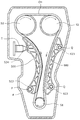
예를 들면, 도 10에 나타내듯이, 엔진 룸(E) 내의 크랭크축과 캠축의 각각에 설치한 스프로켓(S1, S2) 간에 무단현 돌려진 롤러 체인 등의 전동 체인(CH)을 주행시키는 엔진의 타이밍 시스템이며, 타이밍 체인(CH)이 엔진 룸(E) 내의 크랭크 축에 취부한 구동 스프로켓(S1)과 캠 축에 취부한 한 쌍의 종동 스프로켓(S2) 간에 무단현 돌려지고, 이 타이밍 체인(CH)이 요동하는 체인 가이드(요동 가이드)(500)와 체인 가이드(고정 가이드)(600)에 의해서 가이드 되는 타이밍 시스템이 공지이다.For example, as shown in Fig. 10, an engine (not shown) running on the transmission chain CH such as a roller chain, which is continuously wound between the sprockets S1 and S2 provided on the crankshaft and the camshaft, The timing chain CH is tilted continuously between a drive sprocket S1 mounted on a crankshaft in the engine room E and a pair of driven sprockets S2 mounted on the camshaft, CH) is guided by a chain guide (swing guide) 500 and a chain guide (stationary guide) 600, both of which swing.
이 공지의 타이밍 시스템에서는, 고정 가이드(600)는, 2개의 취부축(Q)과 엔진 룸(E) 내에 고정되고, 요동 가이드(500)는, 요동축(P)을 중심으로 타이밍 체인(CH)의 현회평면(懸回平面) 내에서 요동 가능하게 엔진 룸(E) 내에 장착되고 있다.In this known timing system, the
체인 텐셔너(T)는, 요동 가이드(500)를 압압함으로써 타이밍 체인(CH)의 장력을 적정하게 보관 유지함과 동시에 진동을 억제하고 있다.The chain tensioner T appropriately holds the tension of the timing chain CH by pressing the
이러한 타이밍 시스템에 이용되는 공지의 체인 가이드(요동 가이드)(500)는, 도 10, 도 11에 나타내듯이, 안내면(511)을 갖는 안내 슈(510)와 본체부(520)를 구비하고, 본체부(520)는, 안내면(511)의 반대 측으로 연장되는 지지벽(521)을 갖고, 2개소의 지지부로서, 취부 보스부(523)와 텐셔너(T)에 의해 체인 측에 압압되는 압압부(524)를 가지고 있다.A known chain guide (swing guide) 500 used in such a timing system is provided with a
또한, 본체부(520)는, 높이 방향으로 연장되는 보강 리브(522)가 적당한 간격, 형상, 방향으로 설치되어, 본체부(520)의 강성을 높이고 있다.The
또, 체인 가이드(고정 가이드)(600)는, 전술의 체인 가이드(요동 가이드)(500)의 취부 보스부(523), 압압부(524)에 대신하여, 2개소의 지지부로서 2개의 취부축(Q)에 고정하기 위한 2개의 취부 보스부(623)가 설치되고 있다.The chain guide (stationary guide) 600 is provided with two support portions as the two support portions in place of the
또, 체인 가이드(500, 600)에서, 안내 슈(510)와 본체부(520)가 사출 성형 등에 의해 일체적으로 형성된 것도 공지이다.It is also known in the
이러한 공지의 체인 가이드에서는, 도 10의 예와 같이 엔진 룸(E) 내에 취부하는 경우, 그 설치 스페이스에 제약이 있어, 보다 작은 사이즈로 강성이나 내구성을 확보하는 것이 요구될 수 있다.In such a known chain guide, when it is mounted in the engine room E as in the example of Fig. 10, there is a restriction in the installation space, and it may be required to secure rigidity and durability with a smaller size.
그러기 위해서는, 본체부의 지지벽이나 보강 리브의 두께를 증가시키거나, 보강 리브의 수를 늘릴 필요가 있지만, 이러한 대책에서는, 경량화가 곤란해지고, 또, 재료 코스트도 비싸진다고 하는 문제가 있었다.In order to do so, it is necessary to increase the thickness of the support wall or the reinforcing rib of the body portion or to increase the number of the reinforcing ribs. However, in this measure, it is difficult to reduce the weight and the material cost is also increased.
또, 체인으로부터 안내면에 받는 힘에 의해서, 내부 응력이 높이 방향으로 연장되는 보강 리브의 하단부에 집중되는 것은 피하지 못하고, 체인 가이드 전체적으로 강도나 강성은 높아지지만, 국소적인 내부 응력의 집중에 의한 파손의 우려가 남는다고 하는 문제가 있었다.In addition, due to the force exerted on the guide surface from the chain, the internal stress can not be concentrated on the lower end portion of the reinforcing rib extending in the height direction, and the strength and rigidity of the entire chain guide are increased. However, There was a problem that concerns of
또한, 본체부를 사출 성형에 의해 형성하는 경우, 보강 리브가 금형 내에서의 수지의 원활한 유동을 저해하는 요인이 되어, 보강 리브의 두께를 증가시키거나 수를 늘렸을 경우, 수지의 배향성이 불균일하게 되고, 치수 오차, 형상 오차나 내부의 왜곡(internal distortion), 결손(defect) 등이 발생할 우려가 있다고 하는 문제가 있었다.In addition, when the main body is formed by injection molding, the reinforcing rib is a factor that hinders smooth flow of the resin in the mold, and when the thickness of the reinforcing rib is increased or the number is increased, the orientation of the resin becomes uneven , Dimensional errors, shape errors, internal distortions, defects, and the like may occur.
이러한 문제를 저감하기 위해서, 체인으로부터의 압압력의 중심인 본체부의 길이 방향의 중간점 부근으로부터, 그것을 받는 2개소의 지지부를 향해 크게 경사하여 연장되도록 보강 리브를 설치하고, 가장 힘이 걸릴 방향만 보강 리브로 보강하는 것이 공지이다(특허문헌 1 등 참조.).In order to reduce such a problem, a reinforcing rib is provided so as to extend from the vicinity of the midpoint in the longitudinal direction of the main body, which is the center of the pressing force from the chain, toward the two support portions receiving the reinforcement rib, It is known to reinforce it with a reinforcing rib (see Patent Document 1, etc.).
그렇지만, 체인으로부터의 압압력을 2개소의 지지부에서 받기 때문에, 본체부를 굽히는 힘도 발생하지만, 특허문헌 1과 같이 보강 리브를 설치했을 경우, 길이 방향의 중간점 부근에 그 휨 응력이 집중하기 때문에, 이 응력에 의해 길이 방향의 중간점 부근에 집중되어 반복 변형이 발생하고, 내구성의 향상을 방해한다는 문제가 있었다.However, since the pressing force from the chain is received by the two support portions, a force for bending the body portion also occurs. However, when the reinforcing rib is provided as in Patent Document 1, the bending stress concentrates in the vicinity of the midpoint in the longitudinal direction , There is a problem that this stress concentrates in the vicinity of the midpoint in the longitudinal direction to cause repeated deformation, hindering improvement in durability.
또, 보강 리브로부터 먼 길이 방향의 중간점 부근의 비틀림에 대한 강성이 작아진다고 하는 문제가 있었다.In addition, there is a problem that the rigidity against twist near the midpoint in the longitudinal direction far from the reinforcing rib is reduced.
본 발명은, 이러한 문제점을 해결하는 것으로, 간단한 구성으로, 내구성을 향상시키고, 경량화를 가능하게 하여 재료 코스트를 저감함과 동시에, 금형 내에서의 수지의 원활한 유동을 저해하지 않고, 치수 오차, 형상 오차나 내부의 왜곡, 결손 등을 저감하고, 내부 응력의 집중이나, 반복의 휨 변형을 방지할 수 있는 체인 가이드를 제공하는 것을 목적으로 하는 것이다.An object of the present invention is to solve such a problem, and it is an object of the present invention to improve durability and lightness by a simple constitution, to reduce the material cost, and to prevent the smooth flow of the resin in the mold, It is an object of the present invention to provide a chain guide capable of reducing errors, internal distortions, defects, etc., and preventing concentration of internal stress and warping deformation of repetition.
본 청구항 1에 관한 발명은, 주행하는 체인을 접동 안내하는 안내면과, 상기 안내면을 체인 주행 방향을 따라서 지지하는 본체부를 구비하고, 상기 본체부가, 소정의 높이의 지지벽과, 상기 지지벽의 상하 단연 이외의 부분으로부터 측방으로 돌출된 보강 리브를 갖는 체인 가이드이며, 상기 보강 리브가, 횡방향 리브부를 갖고, 상기 본체부가, 길이 방향의 떨어진 위치에 적어도 2개소의 지지부를 갖고, 상기 횡방향 리브부가, 상기 2개소의 지지부 간의 거리(L)에 대해 20% 이상의 길이에 걸쳐서 보강 리브의 다른 부분과는 접속되지 않는 독립 영역을 갖고, 상기 독립 영역이, 상기 지지벽의 높이 치수의 반의 위치보다 상기 안내면에서 먼 측에 설치되고 있는 것으로, 상기 과제를 해결하는 것이다.According to a first aspect of the present invention, there is provided an automatic transmission according to the first aspect of the present invention, comprising: a guide surface slidingly guiding a traveling chain; and a main body portion supporting the guide surface along a chain running direction, Wherein the reinforcing rib has a transverse rib portion and the main body portion has at least two supporting portions at a position spaced apart in the longitudinal direction, and the transverse rib portion And an independent region that is not connected to another portion of the reinforcing rib over a length of 20% or more with respect to a distance L between the two support portions, wherein the independent region has a height And is installed on the side farther from the guide surface.
본 청구항 1에 관한 체인 가이드에 의하면, 보강 리브가 횡방향 리브부를 가지므로, 본체부를 보강하여 내구성이 향상됨과 동시에, 휨이나 뒤틀림 등의 휨 강성을 강화할 수 있다.According to the chain guide of claim 1, since the reinforcing rib has the transverse rib, the body is reinforced to improve the durability and the flexural rigidity such as warping and warping can be enhanced.
또, 본체부가 길이 방향의 떨어진 위치에 적어도 2개소의 지지부를 갖고, 횡방향 리브부가 2개소의 지지부 간의 거리(L)에 대해 20% 이상의 길이에 걸쳐서 보강 리브의 다른 부분과는 접속되지 않는 독립 영역을 가지므로, 체인으로부터 안내면에 받는 힘에 의해서, 내부 응력이 본체부의 하단연의 특정의 개소에 집중되지 않고, 국소적인 내부 응력의 집중에 의한 파손을 방지하는 것이 가능해진다.It is preferable that the main body portion has at least two support portions at positions spaced apart from each other in the lengthwise direction and the lateral ribs are independent of the distance L between the two support portions over a length of 20% It is possible to prevent the internal stress from being concentrated at a specific position of the lower edge of the main body portion by the force exerted on the guide surface from the chain and to prevent breakage due to local concentration of internal stress.
또, 독립 영역이 지지벽의 높이 치수의 반의 위치에서 안내면에서 먼 측에 설치되고 있으므로, 본체부의 길이 방향의 중간점 부근에 휨 응력이 집중했을 때의, 인장 방향으로 내부 응력이 발생하는 부분을 보강 가능하고, 반복 변형을 억제하여, 내구성을 향상할 수 있음과 동시에, 길이 방향의 중간점 부근의 비틀림에 대한 강성을 높일 수 있다.Further, since the independent region is provided on the side far from the guide surface at a half of the height dimension of the support wall, a portion where internal stress is generated in the tensile direction when the bending stress concentrates near the midpoint in the longitudinal direction of the main body It is possible to reinforce it, to suppress the repeated deformation, to improve the durability, and to increase the rigidity against twist in the vicinity of the midpoint in the longitudinal direction.
또한, 종방향의 보강 리브를 감소시키거나, 혹은, 없앨 수 있기 때문에, 제조 시의 금형 내에서의 수지의 유동을 어지럽히는 부분을 적게 하는 것이 가능하고, 내부의 수지의 배향성이 균일화되어, 치수 오차, 형상 오차나 내부의 왜곡, 결손 등을 저감하는 것이 가능하고, 휨이나 뒤틀림 등의 휨 강성을 강화할 수 있다.In addition, since the reinforcing ribs in the longitudinal direction can be reduced or eliminated, it is possible to reduce the number of parts which disturb the flow of the resin in the mold at the time of manufacturing, to make the orientation of the resin uniform, It is possible to reduce the errors, the shape errors, the internal distortions, the defects, and the like, and the flexural rigidity such as warping and warping can be enhanced.
본 청구항 2 기재의 구성에 의하면, 보강 리브가, 횡방향 리브부만으로 구성되어 있으므로, 전체가 경량화됨과 동시에, 제조 시의 금형 내에서의 수지의 유동이 더 균일화된다.According to the configuration of
본 청구항 3 기재의 구성에 의하면, 본체부가 지지벽의 상하 단연을 따라서, 측방으로 돌출된 외연 리브를 갖고, 보강 리브가 횡방향 리브부에서 외연 리브로 연장되는 접속 리브부를 가지므로, 접속 리브부에 의해서 필요한 개소의 강성을 더 높이는 것이 가능함과 동시에, 제조 시의 금형 내에서 외연 리브와 횡방향 리브부와의 수지의 유동이 더 균일화된다.According to the configuration of Claim 3, since the main body portion has the outer ribs protruding sideways along the upper and lower edges of the support wall and the reinforcing rib has the connecting rib portion extending from the transverse rib portion to the outer rib, It is possible to further increase the rigidity of the required portion and to make the flow of the resin between the outer rib and the transverse rib in the mold during manufacturing more uniform.
본 청구항 4 기재의 구성에 의하면, 2개소의 지지부의 적어도 일방이, 지지벽으로부터 측방으로 돌출된 취부 보스부로 구성되어, 횡방향 리브부가 취부 보스부에 접속되고 있으므로, 제조 시의 금형 내에서 취부 보스부와 횡방향 리브부와의 수지의 유동이 균일화된다.According to the configuration of claim 4, at least one of the two support portions is constituted by a mounting boss portion projecting sideward from the support wall, and the transverse rib portion is connected to the mounting boss portion. Therefore, The flow of the resin between the boss portion and the transverse rib portion is made uniform.
본 청구항 5 기재의 구성에 의하면, 보강 리브가, 횡방향 리브부의 독립 영역만으로 구성되어 있으므로, 필요한 강성, 내구성을 확보하면서, 소형 경량화를 가능하게 하고, 재료 코스트를 저감하는 것이 가능해진다.According to the configuration of
본 청구항 6 기재의 구성에 의하면, 독립 영역이 2개소의 지지부 간의 거리(L)에 대해 50% 이상의 길이에 걸쳐서 설치되고 있으므로, 더욱, 전체의 강성을 높임과 동시에, 본체부의 하단연으로의 응력 집중을 완화하여, 반복 변형을 억제할 수 있다.According to the configuration of
[도 1] 본 발명의 제1 실시 형태에 관한 체인 가이드(고정 가이드)의 측면도.
[도 2] 도 1의 사시 설명도.
[도 3] 본 발명과 종래 예의 치수 설명도.
[도 4] 본 발명과 종래 예의 내부 응력 최대치의 그래프.
[도 5] 본 발명의 제2 실시 형태에 관한 체인 가이드(고정 가이드)의 측면도.
[도 6] 본 발명의 제3 실시 형태에 관한 체인 가이드(고정 가이드)의 측면도.
[도 7] 본 발명의 제4 실시 형태에 관한 체인 가이드(고정 가이드)의 측면도.
[도 8] 본 발명의 제5 실시 형태에 관한 체인 가이드(고정 가이드)의 측면도.
[도 9] 본 발명의 제6 실시 형태에 관한 체인 가이드(고정 가이드)의 측면도.
[도 10] 종래의 엔진의 타이밍 시스템의 설명도.
[도 11] 종래의 체인 가이드의 개략 단면 사시도.1 is a side view of a chain guide (stationary guide) according to a first embodiment of the present invention;
Fig. 2 is an explanatory view of Fig. 1;
3 is a schematic explanatory view of the present invention and a conventional example.
4 is a graph showing the maximum internal stresses of the present invention and the conventional example.
5 is a side view of a chain guide (stationary guide) according to a second embodiment of the present invention.
6 is a side view of a chain guide (stationary guide) according to a third embodiment of the present invention.
7 is a side view of a chain guide (stationary guide) according to a fourth embodiment of the present invention.
8 is a side view of a chain guide (stationary guide) according to a fifth embodiment of the present invention.
9 is a side view of a chain guide (stationary guide) according to a sixth embodiment of the present invention.
10 is an explanatory diagram of a timing system of a conventional engine.
11 is a schematic cross-sectional perspective view of a conventional chain guide.
본 발명은, 주행하는 체인을 접동 안내하는 안내면과, 상기 안내면을 체인 주행 방향을 따라서 지지하는 본체부를 구비하고, 상기 본체부가, 소정의 높이의 지지벽과, 상기 지지벽의 상하 단연(端緣) 이외의 부분으로부터 측방으로 돌출된 보강 리브를 갖는 체인 가이드이며, 상기 보강 리브가, 횡방향 리브부를 갖고, 상기 본체부가, 길이 방향의 떨어진 위치에 적어도 2개소의 지지부를 갖고, 상기 횡방향 리브부가, 상기 2개소의 지지부 간의 거리(L)에 대해 20% 이상의 길이에 걸쳐서 보강 리브의 다른 부분과는 접속되지 않는 독립 영역을 갖고, 상기 독립 영역이, 상기 지지벽의 높이 치수의 반의 위치보다 상기 안내면에서 먼 측에 설치되어, 간단한 구성으로, 내구성을 향상시키고, 경량화를 가능하게 하여 재료 코스트를 저감함과 동시에, 금형 내에서의 수지의 원활한 유동을 저해하지 않고, 치수 오차, 형상 오차나 내부의 왜고, 결손 등을 저감하고, 내부 응력의 집중이나, 반복의 휨 변형을 방지할 수 있는 것이면, 그 구체적인 구성은 어떠한 것이어도 좋다.The present invention is characterized in that it comprises a guide surface for slidingly guiding a running chain and a main body portion for supporting the guide surface along the chain running direction, wherein the main body portion includes a support wall having a predetermined height, , Wherein the reinforcing rib has a transverse rib portion and the main body portion has at least two supporting portions at a position spaced apart in the longitudinal direction, and the transverse rib portion And an independent region that is not connected to another portion of the reinforcing rib over a length of 20% or more with respect to a distance L between the two support portions, wherein the independent region has a height And is provided on the side farther from the guide surface to improve the durability and the lighter weight by a simple structure to reduce the material cost, Any specific structure may be used as long as it can reduce the dimensional error, the shape error, the internal distortion, the defect, and the like without preventing the smooth flow of the resin and preventing the concentration of the internal stress and the warping deformation .
본체부, 안내면은 별체이거나 일체로 형성되고 있어도 좋고, 또 재질은, 각각, 강성, 접동 특성, 성형성, 코스트 등에 따라 공지의 적당의 것을 선택하면 좋다.The body portion and the guide surface may be separate or integrally formed, and the material may be appropriately selected according to the rigidity, sliding characteristics, formability, cost, and the like.
[실시예 1][Example 1]
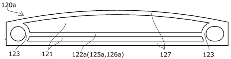
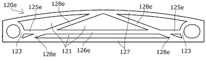
본 발명의 제1 실시 형태에 관한 체인 가이드(고정 가이드)는, 타이밍 시스템을 갖는 엔진 내에 고정되어, 타이밍 체인(CH)의 주행을 가이드 하여 안정시키는 것으로, 도 1, 도 2에 나타내듯이 상방에 안내면(도시하지 않음)을 일체로 갖는 본체부(120)를 구비하고 있다.The chain guide (stationary guide) according to the first embodiment of the present invention is fixed in an engine having a timing system to guide and stabilize the running of the timing chain CH, and as shown in Figs. 1 and 2, And a
본체부(120)는, 전술의 공지의 체인 가이드(요동 가이드)(500)와 동일하게, 지지벽(121)의 길이 방향 양단부에 엔진 등에의 취부부인 2개소의 취부 보스부(mounting boss)(123)를 갖고, 지지벽(121)의 상단연 및 하단연에는, 2개소의 취부 보스부(123)를 묶어 지지벽(121)의 측방으로는 외측에 외연 리브(127)가 설치되어, 본체부(120)의 강성, 내구성을 높이고 있다.The
또한, 안내면(도시하지 않음)은, 본체부(120)의 상방에 고정되어도 좋고, 본체부(120)의 표면을 접동 안내면으로서 형성하여, 안내면의 기능을 일체화해도 좋다.The guide surface (not shown) may be fixed above the
본 실시 형태에서는, 보강 리브(122)는, 길이 방향의 떨어진 위치의 2개소의 지지부(Pt)(취부 보스부(123)의 중심)를 묶는 방향으로 연장되는 횡방향 리브부(125)만으로 구성되고, 다른 부분과는 접속되지 않는 독립 영역(independent zone)(126)만으로 구성되어 있다.In the present embodiment, the reinforcing rib 122 is constituted only by the transverse ribs 125 extending in the bundling direction of the two support portions Pt (the center of the mounting boss 123) And an
도 3에 나타내듯이, 독립 영역(126)의 길이(Ld)는, 2개소의 지지부(Pt) 간의 거리(L)에 대해 20% 이상이며, 독립 영역(126)은 지지벽(121)의 높이 치수(H)의 반(H/2)의 위치보다 안내면에서 먼 측에 설치되고 있다.3, the length Ld of the
이것에 의해서, 체인으로부터 안내면에 받는 힘에 의해서, 내부 응력이 본체부(120)의 하단연의 특정의 개소에 집중되지 않고, 국소적인 내부 응력의 집중에 의한 파손을 방지하는 것이 가능해진다.This makes it possible to prevent the internal stress from being concentrated at a specific position of the lower end edge of the
또, 본체부(120)에 걸리는 휨 응력은, 지지벽(121)의 높이 치수(H)의 반(H/2)의 위치보다 위(안내면측)에서는 압축 응력, 반(H/2)의 위치보다 아래(안내면에서 먼 측)에서는 인장 응력이 되고, 이것이 반복됨으로써 특히 인장 응력이 되는 반(H/2)의 위치보다 아래가 파손되기 쉬워진다.The bending stress applied to the
본 발명에서는, 독립 영역(126)이 지지벽(121)의 높이 치수(H)의 반(H/2)의 위치보다 안내면에서 먼 측에 설치되고 있으므로, 보강됨과 동시에, 인장 응력이 분산하여 중앙 부근으로의 집중이 완화되어, 파손을 막는 것이 가능해진다.Since the
도 3의 하단에 나타내는 제1 실시 형태에 관한 체인 가이드의 본체부(120)의 독립 영역(126)이 길이(Ld), 높이 위치(Hd)를 변화시켰을 때에, 하단의 외연 리브로의 최대 응력의 해석 결과를, 도 4에 나타낸다.When the length Ld and the height position Hd of the
도 4의 왼쪽의 Ld/L=0, 및, 오른쪽의 리브 없음의 결과는, 도 3의 상단에 나타내는, 비교예 체인 가이드(700)(제1 실시 형태에 관한 체인 가이드의 본체부(120)로부터 보강 리브(122)를 없앤 것)에 의한 해석 결과이다.The result of Ld / L = 0 on the left side of FIG. 4 and the result of the absence of the right side of the chain guide of the comparative example (the
도 4의 왼쪽의 Ld/L의 해석 결과로부터 알수 있듯이, 실용상, Ld/L≥20%로, 충분한 응력 저감 효과를 얻는 것이 가능하고, Ld/L≒50%까지는 거의 리니어하게 응력 저감 효과가 커지므로, Ld/L≥50%로 하는 것이 매우 적합하다.As can be seen from the analysis result of Ld / L on the left side of Fig. 4, it is possible to obtain a sufficient stress reduction effect in practical use with Ld / L? 20%, and a stress reduction effect almost linearly up to Ld / L? 50% It is very suitable to set Ld / L? 50%.
또, 도 4의 오른쪽의 Hd/H의 해석 결과로부터 알수 있듯이, 제1 실시 형태에 관한 체인 가이드에서는, 리브의 높이 위치 Hd/H가 50%를 초과하면 압축 응력 부분을 보강하게 되어, 하단의 외연 리브로의 최대 응력은 오히려 커진다.As can be seen from the analysis result of Hd / H on the right side of Fig. 4, in the chain guide according to the first embodiment, when the height position Hd / H of the rib exceeds 50%, the compressive stress portion is reinforced, The maximum stress of the outer ribs becomes rather large.
따라서, Hd/H≤50%, 즉, 독립 영역이 지지벽의 높이 치수(H)의 반(H/2)의 위치보다 안내면에서 먼 측에 설치되는 것이 매우 적합하다.Therefore, it is preferable that Hd / H? 50%, that is, the independent region is provided on the side farther from the guide surface than the position of half (H / 2) of the height dimension H of the support wall.
[실시예 2][Example 2]
본 발명의 제2 실시 형태에 관한 체인 가이드(고정 가이드)의 본체부(120a)는, 도 5에 나타내듯이, 보강 리브(122a)가, 길이 방향의 떨어진 위치의 2개소의 지지부(Pt)(취부 보스부(123)의 중심)를 묶는 방향으로 연장되는 횡방향 리브부(125a)만으로 구성되고, 양단이 취부 보스부(123)와 접속됨과 동시에, 전체가 다른 부분과는 접속되지 않는 독립 영역(126a)으로 구성되어 있다.5, the
이것으로, Ld/L가 100%에 가깝게 되어, 최대한의 응력 저감 효과를 발휘할 수 있다.With this, Ld / L becomes close to 100%, and the maximum stress reducing effect can be exhibited.
[실시예 3][Example 3]
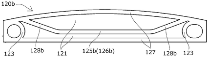
본 발명의 제3 실시 형태에 관한 체인 가이드(고정 가이드)의 본체부(120b)는, 도 6에 나타내듯이, 보강 리브가, 길이 방향의 떨어진 위치의 2개소의 지지부(Pt)(취부 보스부(123)의 중심)를 묶는 방향으로 연장되는 횡방향 리브부(125b)와, 그 양단으로부터 상방의 외연 리브(127)를 향해 연장되는 2개소의 접속 리브부(128b)로 구성되어 있다.As shown in Fig. 6, the
2개소의 접속 리브부(128b)는, 각각 취부 보스부(123)의 근방에서 외연 리브(127)와 접속되고 있다.The two
이것으로, 필요한 길이의 독립 영역(126b)을 확보하면서, 금형 내에서의 수지의 원활한 유동을 가능하게 하고, 치수 오차, 형상 오차나 내부의 왜곡(internal distortion), 결손(defect) 등을 저감할 수 있다.This makes it possible to smoothly flow the resin in the mold while securing the
[실시예 4][Example 4]
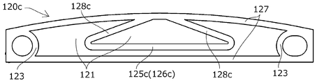
본 발명의 제4 실시 형태에 관한 체인 가이드(고정 가이드)의 본체부(120c)는, 도 7에 나타내듯이, 보강 리브가, 길이 방향의 떨어진 위치의 2개소의 지지부(Pt)(취부 보스부(123)의 중심)를 묶는 방향으로 연장되는 횡방향 리브부(125c)와, 그 양단으로부터 상방의 외연 리브(127)를 향해 연장되는 2개소의 접속 리브부(128c)로 구성되어 있다.7, the
2개소의 접속 리브부(128c)는, 각각 길이 방향 중앙 부근에서 외연 리브(127)와 접속되고 있다.The two
이것으로, 체인으로부터의 압압력의 가장 커지는 외연 리브(127)의 중앙 부근의 힘을 접속 리브부(128c)와 횡방향 리브부(125c)까지 전함으로써 보강하는 것이 가능해져, 작은 리브 길이로 종방향의 보강도 충분히 실시하는 것이 가능해진다.As a result, it is possible to reinforce by applying a force in the vicinity of the center of the outer
[실시예 5][Example 5]
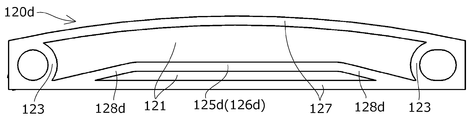
본 발명의 제5 실시 형태에 관한 체인 가이드(고정 가이드)의 본체부(120d)는, 도 8에 나타내듯이, 보강 리브가, 길이 방향의 떨어진 위치의 2개소의 지지부(Pt)(취부 보스부(123)의 중심)를 묶는 방향으로 연장되는 횡방향 리브부(125d)와, 그 양단으로부터 하부의 외연 리브(127)를 향해 연장되는 2개소의 접속 리브부(128d)로 구성되어 있다.The
2개소의 접속 리브부(128d)는, 각각 취부 보스부(123)의 근방에서 외연 리브(127)와 접속되고 있다.Two
이것으로, 필요한 길이의 독립 영역(126d)를 확보하면서, 금형 내에서의 수지의 원활한 유동을 가능하게 하고, 치수 오차, 형상 오차나 내부의 왜곡, 결손 등을 저감할 수 있다.This makes it possible to smoothly flow the resin in the mold while securing the
[실시예 6][Example 6]
본 발명의 제6 실시 형태에 관한 체인 가이드(고정 가이드)의 본체부(120e)는, 도 9에 나타내듯이, 보강 리브가, 길이 방향의 떨어진 위치의 2개소의 지지부(Pt)(취부 보스부(123)의 중심)를 묶는 방향으로 연장되고, 양단이 취부 보스부(123)와 접속되는 횡방향 리브부(125e)와, 상방의 외연 리브(127)의 중앙 부근으로부터, 하부의 외연 리브(127)의 취부 보스부(123) 부근을 향해 연장되는 2개소의 접속 리브부(128e)로 구성되어 있다.The
횡방향 리브부(125e)와 2개소의 접속 리브부(128e)는, 각각 교차상으로 접속되어, 2개의 교차부의 사이에 독립 영역(126e)이 구성되어 있다.The
이것으로, 필요한 길이의 독립 영역(126e)을 확보하면서, 금형 내에서의 수지의 원활한 유동을 가능하게 하고, 치수 오차, 형상 오차나 내부의 왜곡, 결손 등을 저감할 수 있음과 동시에, 체인으로부터의 압압력의 가장 커지는 외연 리브(127)의 중앙 부근의 힘을 접속 리브부(128e)에 의해서 양단 방향으로 분산시키는 것이 가능해진다.This makes it possible to smoothly flow the resin in the mold while securing the
또, 횡방향 리브부(125e)와 2개소의 접속 리브부(128e)를 교차상으로 접속함으로써, 본체부(120e)의 휨(flexure)이나 비틀림(torsion)에 대한 강성을 높일 수 있다.By connecting the
이상 설명한 각 실시 형태는, 본 발명에 관한 체인 가이드의 구체적인 예이지만, 본 발명에 관한 체인 가이드는 이것들로 한정되지 않고, 각 구성 부재의 형상, 위치, 치수, 배치 관계 등, 여러 가지 변형이 가능하다.Each of the embodiments described above is a specific example of the chain guide according to the present invention. However, the chain guide according to the present invention is not limited to these, and various modifications such as the shape, position, Do.
예를 들면, 각 실시 형태는 고정 가이드로서 사용되는 형태를 나타냈지만, 2개소의 지지부의 일방을 텐셔너에 의한 압압부로서 요동 가이드로서 사용되는 것이어도 좋다.For example, although each embodiment is shown as being used as a fixed guide, one of the two support portions may be used as a swing guide as a pressing portion by a tensioner.
또, 각 실시 형태는 2개소의 지지부를 갖는 체인 가이드이지만, 3개소 이상의 지지부를 갖는 것이어도 좋고, 그 경우, 횡방향 리브부는, 임의의 2개소의 지지부의 사이의 적어도 1개소, 예를 들면, 체인 주행 방향으로 가장 긴 간격을 갖는 인접하는 2개소의 지지부의 사이에 설치함으로써, 응력의 저감을 도모하는 것이 가능해진다.Each of the embodiments is a chain guide having two support portions, but may have three or more support portions. In this case, the lateral rib portion may be a chain guide having at least one support portion between any two support portions, for example, , And between the two adjacent support portions having the longest interval in the chain running direction, the stress can be reduced.
또, 보강 리브의 지지벽으로부터 측방으로의 돌출 높이, 폭, 단면 형상 등은 임의로 결정하면 좋고, 또, 각 실시 형태는 중앙을 경계로 좌우 대칭의 형태의 것을 나타냈지만, 좌우 다른 형태라고 해도 좋고, 상술한 실시 형태 이외의 다른 형태를 채용해도 좋다.The height, width, and cross-sectional shape of the reinforcing rib projecting sideward from the support wall may be arbitrarily determined, and each of the embodiments has a symmetrical shape with the center as a boundary. However, , But other forms other than the above-described embodiment may be employed.
또한, 지지벽의 상하 단연(端緣)의 외연 리브의 지지벽으로부터 측방으로의 돌출 높이, 폭, 단면 형상 등도 어떠한 것이어도 좋고, 생략되어도 좋다.Further, the projecting height, width, sectional shape, etc. of the outer edge ribs of the upper and lower edges of the support wall from the support wall may be omitted or may be omitted.
또, 전술한 각 실시 형태는, 타이밍 시스템을 갖는 엔진 내에 설치되는 것이지만, 이것으로 한정되지 않고 여러 가지 기기류에 적용 가능하다.Each of the above-described embodiments is provided in an engine having a timing system, but the invention is not limited to this and is applicable to various types of equipment.
또, 체인에 의한 전동 기구에 한정하지 않고, 벨트, 로프 등의 유사한 전동 기구에 적용되어도 좋고, 여러 가지의 산업분야에서 이용 가능하다.The present invention is not limited to a transmission mechanism using a chain, but may be applied to a similar transmission mechanism such as a belt or a rope, and may be used in various industrial fields.
500···체인 가이드(요동 가이드)
100, 600···체인 가이드(고정 가이드)
700···체인 가이드(고정 가이드: 비교예)
510···안내 슈
511···안내면
512···리브
120, 520···본체부
121, 521···지지벽
122, 522···보강 리브
123, 523···취부 보스부
524···압압부
125···횡방향 리브부
126···독립 영역
127···외연 리브
128···접속 리브부
E···엔진 룸
S1···구동 스프로켓
S2···종동 스프로켓
CH···타이밍 체인
Q···취부축
P···요동축
T···체인 텐셔너
Pt···지지부
L···지지부 간 거리
H···지지벽의 높이500 · · · Chain guide (swing guide)
100, 600 · · · · Chain guide (fixing guide)
700 · · · Chain guide (fixed guide: comparative example)
510 ··· Guide Shoe
511 ... guide surface
512 ... rib
120, 520 ...,
121, 521 ... supporting wall
122, 522 ... reinforcing ribs
123, 523 ... mounting boss portion
524 ... pressing portion
125 ... < / RTI >
126 ... Independent area
127 ... outer rib
128 ... connection rib portion
E ... engine room
S1 ... Drive sprocket
S2 · · · driven sprocket
CH ... timing chain
Q:
P ... yaw axis
T ... chain tensioner
Pt: Support
L · · · Distance between supports
H ... height of supporting wall
Claims (6)
상기 보강 리브가, 횡방향 리브부를 갖고,
상기 본체부가, 길이 방향의 떨어진 위치에 적어도 2개소의 지지부를 갖고,
상기 횡방향 리브부가, 상기 2개소의 지지부 간의 거리 L에 대해 20% 이상의 길이에 걸쳐서 보강 리브의 다른 부분과는 접속되지 않는 독립 영역(independent zone)을 갖고,
상기 독립 영역이, 상기 지지벽의 높이 치수의 반의 위치보다 상기 안내면에서 먼 측에 설치되고 있는 것을 특징으로 하는 체인 가이드.
And a main body portion for supporting the guide surface along the running direction of the chain, wherein the main body portion includes a support wall having a predetermined height and protruding laterally from a portion other than upper and lower edges of the support wall A chain guide having reinforcing ribs,
Wherein the reinforcing rib has a transverse rib,
Wherein the main body portion has at least two support portions at positions spaced apart in the longitudinal direction,
The transverse rib portion has an independent zone which is not connected to other portions of the reinforcing rib over a length of 20% or more with respect to the distance L between the two support portions,
Wherein the independent region is provided on a side farther from the guide surface than a half position of the height dimension of the support wall.
상기 보강 리브가, 횡방향 리브부만으로 구성되어 있는 것을 특징으로 하는 체인 가이드.
The method according to claim 1,
Wherein the reinforcing rib is composed of only the transverse ribs.
상기 본체부가, 상기 지지벽의 상하 단연(端緣)을 따라서, 측방으로 돌출된 외연 리브를 갖고,
상기 보강 리브가, 상기 횡방향 리브부로부터 상기 외연 리브에 연장되는 접속 리브부를 갖는 것을 특징으로 하는 체인 가이드.
The method according to claim 1,
Wherein the main body portion has an outer rib projecting sideways along upper and lower edges of the support wall,
Wherein the reinforcing rib has a connecting rib portion extending from the transverse rib portion to the outer rib.
상기 2개소의 지지부의 적어도 일방이, 상기 지지벽으로부터 측방으로 돌출된 취부 보스부(mounting boss)로 구성되고,
상기 횡방향 리브부가, 상기 취부 보스부에 접속되고 있는 것을 특징으로 하는 체인 가이드.
The method according to claim 1,
Wherein at least one of the two support portions comprises a mounting boss projecting laterally from the support wall,
And the lateral rib portion is connected to the mounting boss portion.
상기 보강 리브가, 횡방향 리브부의 독립 영역만으로 구성되어 있는 것을 특징으로 하는 체인 가이드.
The method according to claim 1,
Wherein the reinforcing rib is constituted by only the independent region of the transverse rib portion.
상기 독립 영역이, 상기 2개소의 지지부 간의 거리 L에 대해 50% 이상의 길이에 걸쳐서 설치되고 있는 것을 특징으로 하는 체인 가이드.The method according to claim 1,
Wherein the independent region is provided over a length of 50% or more with respect to a distance L between the two support portions.
Applications Claiming Priority (2)
| Application Number | Priority Date | Filing Date | Title |
|---|---|---|---|
| JP2017033208A JP6823261B2 (en) | 2017-02-24 | 2017-02-24 | Chain guide |
| JPJP-P-2017-033208 | 2017-02-24 |
Publications (2)
| Publication Number | Publication Date |
|---|---|
| KR20180098135A true KR20180098135A (en) | 2018-09-03 |
| KR102050303B1 KR102050303B1 (en) | 2019-11-29 |
Family
ID=63112341
Family Applications (1)
| Application Number | Title | Priority Date | Filing Date |
|---|---|---|---|
| KR1020180016268A Active KR102050303B1 (en) | 2017-02-24 | 2018-02-09 | Chain guide |
Country Status (5)
| Country | Link |
|---|---|
| US (1) | US10753437B2 (en) |
| JP (1) | JP6823261B2 (en) |
| KR (1) | KR102050303B1 (en) |
| CN (1) | CN108506435B (en) |
| DE (1) | DE102018201732B4 (en) |
Families Citing this family (3)
| Publication number | Priority date | Publication date | Assignee | Title |
|---|---|---|---|---|
| JP7177342B2 (en) * | 2018-10-16 | 2022-11-24 | 株式会社椿本チエイン | chain guide |
| JP7212072B2 (en) * | 2019-01-22 | 2023-01-24 | 大同工業株式会社 | CHAIN GUIDE AND CHAIN TRANSMISSION USING THE SAME |
| JP2021025538A (en) * | 2019-07-31 | 2021-02-22 | Ntn株式会社 | Electric actuator |
Citations (4)
| Publication number | Priority date | Publication date | Assignee | Title |
|---|---|---|---|---|
| JPH1130297A (en) * | 1997-07-08 | 1999-02-02 | Nok Corp | Chain guide |
| JP2009501887A (en) | 2005-07-20 | 2009-01-22 | ディーエスエム アイピー アセッツ ビー.ブイ. | Guide for transmission |
| KR20140111958A (en) * | 2013-03-12 | 2014-09-22 | 가부시기가이샤쯔바기모도체인 | Chain guide |
| KR20150011312A (en) * | 2013-07-22 | 2015-01-30 | 가부시기가이샤쯔바기모도체인 | Chain guide |
Family Cites Families (12)
| Publication number | Priority date | Publication date | Assignee | Title |
|---|---|---|---|---|
| DE3706136C1 (en) * | 1987-02-26 | 1988-09-15 | Porsche Ag | Process for manufacturing a chain tensioner |
| JPH08145132A (en) * | 1994-11-22 | 1996-06-04 | Hokushin Ind Inc | Chain guide |
| US5690569A (en) * | 1996-03-13 | 1997-11-25 | Borg-Warner Automotive, Inc. | Single piece reinforced chain guide |
| US6013000A (en) * | 1998-08-14 | 2000-01-11 | Tmj Properties, L.L.C. | Polymeric chain guide |
| JP2001323976A (en) * | 2000-05-15 | 2001-11-22 | Honda Motor Co Ltd | Chain guide member, chain guide member manufacturing method, and chain guide member manufacturing apparatus |
| JP3398143B2 (en) * | 2001-09-11 | 2003-04-21 | 株式会社椿本チエイン | Synthetic resin guide for transmission |
| DE10244734B4 (en) | 2002-09-26 | 2013-01-17 | Carl Freudenberg Kg | chain drive |
| DE10302876A1 (en) | 2003-01-25 | 2004-08-05 | Ina-Schaeffler Kg | Unit with a sleeve for chain timing drives |
| DE102005018901A1 (en) * | 2005-04-22 | 2006-11-16 | Schaeffler Kg | Traction drive with at least one rail for tensioning and / or guiding an endless traction means |
| DE102013216806A1 (en) | 2013-08-23 | 2015-02-26 | Schaeffler Technologies Gmbh & Co. Kg | Clamp or guide rail for a traction mechanism drive on an internal combustion engine of a vehicle |
| US9476485B2 (en) * | 2014-03-14 | 2016-10-25 | Ford Global Technologies, Llc | Diamond-like carbon coating on chain guides and tensioning arms for internal combustion engines |
| KR101923657B1 (en) * | 2017-01-12 | 2018-11-30 | 유신정밀공업 주식회사 | Chain Tensioner |
-
2017
- 2017-02-24 JP JP2017033208A patent/JP6823261B2/en active Active
-
2018
- 2018-01-24 CN CN201810069909.0A patent/CN108506435B/en active Active
- 2018-02-05 DE DE102018201732.8A patent/DE102018201732B4/en active Active
- 2018-02-06 US US15/889,618 patent/US10753437B2/en active Active
- 2018-02-09 KR KR1020180016268A patent/KR102050303B1/en active Active
Patent Citations (4)
| Publication number | Priority date | Publication date | Assignee | Title |
|---|---|---|---|---|
| JPH1130297A (en) * | 1997-07-08 | 1999-02-02 | Nok Corp | Chain guide |
| JP2009501887A (en) | 2005-07-20 | 2009-01-22 | ディーエスエム アイピー アセッツ ビー.ブイ. | Guide for transmission |
| KR20140111958A (en) * | 2013-03-12 | 2014-09-22 | 가부시기가이샤쯔바기모도체인 | Chain guide |
| KR20150011312A (en) * | 2013-07-22 | 2015-01-30 | 가부시기가이샤쯔바기모도체인 | Chain guide |
Also Published As
| Publication number | Publication date |
|---|---|
| KR102050303B1 (en) | 2019-11-29 |
| DE102018201732B4 (en) | 2024-08-08 |
| JP2018138793A (en) | 2018-09-06 |
| US10753437B2 (en) | 2020-08-25 |
| CN108506435B (en) | 2021-01-01 |
| DE102018201732A1 (en) | 2018-08-30 |
| JP6823261B2 (en) | 2021-02-03 |
| US20180245673A1 (en) | 2018-08-30 |
| CN108506435A (en) | 2018-09-07 |
Similar Documents
| Publication | Publication Date | Title |
|---|---|---|
| JP5848277B2 (en) | Chain guide | |
| KR20180098135A (en) | Chain guide | |
| US7896766B2 (en) | Side bow conveyor chain with inner and outer chain links | |
| KR101659392B1 (en) | Chain guide | |
| KR101732448B1 (en) | Chain guide | |
| US20050200044A1 (en) | Synthetic resin guide for transmission device | |
| CN111946782B (en) | Tensioning rod | |
| US8057336B2 (en) | Guide device for an endless torque-transmitting means, and mold for producing a guide device | |
| JPS5894437A (en) | Injection molding machine for plastic | |
| RU2014130988A (en) | FRAME SEAT BACK STRUCTURE | |
| US8859867B2 (en) | String tension support structure | |
| US20140213401A1 (en) | Chain guide | |
| CN1443131A (en) | Slide rail device for conveyor | |
| KR20180070122A (en) | Mount structure of wheel resonator for vehicle, and mounting method thereof | |
| KR20140082933A (en) | Chain guide | |
| RU2661240C1 (en) | Direction chain | |
| US20150369345A1 (en) | Tensioning rail with resilient press-on region | |
| KR101971321B1 (en) | Chain guide | |
| US20140274513A1 (en) | Chain guide | |
| CN102954165B (en) | Guide rail or tensioning rail of a traction mechanism drive and traction mechanism drive | |
| KR101608759B1 (en) | Chain guide | |
| KR20200042850A (en) | Chain guide | |
| US11920651B2 (en) | Bracket | |
| US7690409B2 (en) | Connecting and guide element for a tire chain | |
| US11447190B2 (en) | Structure for reinforcing framework member in vehicle |
Legal Events
| Date | Code | Title | Description |
|---|---|---|---|
| PA0109 | Patent application |
Patent event code: PA01091R01D Comment text: Patent Application Patent event date: 20180209 |
|
| PG1501 | Laying open of application | ||
| A201 | Request for examination | ||
| PA0201 | Request for examination |
Patent event code: PA02012R01D Patent event date: 20181005 Comment text: Request for Examination of Application Patent event code: PA02011R01I Patent event date: 20180209 Comment text: Patent Application |
|
| E701 | Decision to grant or registration of patent right | ||
| PE0701 | Decision of registration |
Patent event code: PE07011S01D Comment text: Decision to Grant Registration Patent event date: 20191028 |
|
| GRNT | Written decision to grant | ||
| PR0701 | Registration of establishment |
Comment text: Registration of Establishment Patent event date: 20191125 Patent event code: PR07011E01D |
|
| PR1002 | Payment of registration fee |
Payment date: 20191126 End annual number: 3 Start annual number: 1 |
|
| PG1601 | Publication of registration | ||
| FPAY | Annual fee payment |
Payment date: 20221102 Year of fee payment: 4 |
|
| PR1001 | Payment of annual fee |
Payment date: 20221102 Start annual number: 4 End annual number: 4 |
|
| PR1001 | Payment of annual fee |
Payment date: 20231101 Start annual number: 5 End annual number: 5 |
|
| PR1001 | Payment of annual fee |
Payment date: 20241029 Start annual number: 6 End annual number: 6 |