KR20180098132A - Substrate processing method and substrate processing apparatus - Google Patents
Substrate processing method and substrate processing apparatus Download PDFInfo
- Publication number
- KR20180098132A KR20180098132A KR1020180011366A KR20180011366A KR20180098132A KR 20180098132 A KR20180098132 A KR 20180098132A KR 1020180011366 A KR1020180011366 A KR 1020180011366A KR 20180011366 A KR20180011366 A KR 20180011366A KR 20180098132 A KR20180098132 A KR 20180098132A
- Authority
- KR
- South Korea
- Prior art keywords
- substrate
- liquid
- liquid film
- periphery
- surface tension
- Prior art date
- Legal status (The legal status is an assumption and is not a legal conclusion. Google has not performed a legal analysis and makes no representation as to the accuracy of the status listed.)
- Granted
Links
Images


Classifications
-
- H—ELECTRICITY
- H10—SEMICONDUCTOR DEVICES; ELECTRIC SOLID-STATE DEVICES NOT OTHERWISE PROVIDED FOR
- H10P—GENERIC PROCESSES OR APPARATUS FOR THE MANUFACTURE OR TREATMENT OF DEVICES COVERED BY CLASS H10
- H10P72/00—Handling or holding of wafers, substrates or devices during manufacture or treatment thereof
- H10P72/04—Apparatus for manufacture or treatment
- H10P72/0402—Apparatus for fluid treatment
- H10P72/0406—Apparatus for fluid treatment for cleaning followed by drying, rinsing, stripping, blasting or the like
- H10P72/0408—Apparatus for fluid treatment for cleaning followed by drying, rinsing, stripping, blasting or the like for drying
-
- H01L21/02052—
-
- H—ELECTRICITY
- H10—SEMICONDUCTOR DEVICES; ELECTRIC SOLID-STATE DEVICES NOT OTHERWISE PROVIDED FOR
- H10P—GENERIC PROCESSES OR APPARATUS FOR THE MANUFACTURE OR TREATMENT OF DEVICES COVERED BY CLASS H10
- H10P70/00—Cleaning of wafers, substrates or parts of devices
- H10P70/10—Cleaning before device manufacture, i.e. Begin-Of-Line process
- H10P70/15—Cleaning before device manufacture, i.e. Begin-Of-Line process by wet cleaning only
-
- H—ELECTRICITY
- H10—SEMICONDUCTOR DEVICES; ELECTRIC SOLID-STATE DEVICES NOT OTHERWISE PROVIDED FOR
- H10P—GENERIC PROCESSES OR APPARATUS FOR THE MANUFACTURE OR TREATMENT OF DEVICES COVERED BY CLASS H10
- H10P70/00—Cleaning of wafers, substrates or parts of devices
- H10P70/20—Cleaning during device manufacture
-
- H01L21/02307—
-
- H01L21/6704—
-
- H01L21/6715—
-
- H01L21/67242—
-
- H—ELECTRICITY
- H10—SEMICONDUCTOR DEVICES; ELECTRIC SOLID-STATE DEVICES NOT OTHERWISE PROVIDED FOR
- H10P—GENERIC PROCESSES OR APPARATUS FOR THE MANUFACTURE OR TREATMENT OF DEVICES COVERED BY CLASS H10
- H10P14/00—Formation of materials, e.g. in the shape of layers or pillars
- H10P14/60—Formation of materials, e.g. in the shape of layers or pillars of insulating materials
- H10P14/65—Formation of materials, e.g. in the shape of layers or pillars of insulating materials characterised by treatments performed before or after the formation of the materials
- H10P14/6502—Formation of materials, e.g. in the shape of layers or pillars of insulating materials characterised by treatments performed before or after the formation of the materials of treatments performed before formation of the materials
- H10P14/6508—Formation of materials, e.g. in the shape of layers or pillars of insulating materials characterised by treatments performed before or after the formation of the materials of treatments performed before formation of the materials by exposure to a liquid
-
- H—ELECTRICITY
- H10—SEMICONDUCTOR DEVICES; ELECTRIC SOLID-STATE DEVICES NOT OTHERWISE PROVIDED FOR
- H10P—GENERIC PROCESSES OR APPARATUS FOR THE MANUFACTURE OR TREATMENT OF DEVICES COVERED BY CLASS H10
- H10P70/00—Cleaning of wafers, substrates or parts of devices
- H10P70/20—Cleaning during device manufacture
- H10P70/23—Cleaning during device manufacture during, before or after processing of insulating materials
- H10P70/234—Cleaning during device manufacture during, before or after processing of insulating materials the processing being the formation of vias or contact holes
-
- H—ELECTRICITY
- H10—SEMICONDUCTOR DEVICES; ELECTRIC SOLID-STATE DEVICES NOT OTHERWISE PROVIDED FOR
- H10P—GENERIC PROCESSES OR APPARATUS FOR THE MANUFACTURE OR TREATMENT OF DEVICES COVERED BY CLASS H10
- H10P70/00—Cleaning of wafers, substrates or parts of devices
- H10P70/50—Cleaning of wafers, substrates or parts of devices characterised by the part to be cleaned
-
- H—ELECTRICITY
- H10—SEMICONDUCTOR DEVICES; ELECTRIC SOLID-STATE DEVICES NOT OTHERWISE PROVIDED FOR
- H10P—GENERIC PROCESSES OR APPARATUS FOR THE MANUFACTURE OR TREATMENT OF DEVICES COVERED BY CLASS H10
- H10P72/00—Handling or holding of wafers, substrates or devices during manufacture or treatment thereof
- H10P72/04—Apparatus for manufacture or treatment
- H10P72/0402—Apparatus for fluid treatment
- H10P72/0406—Apparatus for fluid treatment for cleaning followed by drying, rinsing, stripping, blasting or the like
- H10P72/0411—Apparatus for fluid treatment for cleaning followed by drying, rinsing, stripping, blasting or the like for wet cleaning or washing
- H10P72/0414—Apparatus for fluid treatment for cleaning followed by drying, rinsing, stripping, blasting or the like for wet cleaning or washing using mainly spraying means, e.g. nozzles
-
- H—ELECTRICITY
- H10—SEMICONDUCTOR DEVICES; ELECTRIC SOLID-STATE DEVICES NOT OTHERWISE PROVIDED FOR
- H10P—GENERIC PROCESSES OR APPARATUS FOR THE MANUFACTURE OR TREATMENT OF DEVICES COVERED BY CLASS H10
- H10P72/00—Handling or holding of wafers, substrates or devices during manufacture or treatment thereof
- H10P72/04—Apparatus for manufacture or treatment
- H10P72/0448—Apparatus for applying a liquid, a resin, an ink or the like
-
- H—ELECTRICITY
- H10—SEMICONDUCTOR DEVICES; ELECTRIC SOLID-STATE DEVICES NOT OTHERWISE PROVIDED FOR
- H10P—GENERIC PROCESSES OR APPARATUS FOR THE MANUFACTURE OR TREATMENT OF DEVICES COVERED BY CLASS H10
- H10P72/00—Handling or holding of wafers, substrates or devices during manufacture or treatment thereof
- H10P72/06—Apparatus for monitoring, sorting, marking, testing or measuring
-
- H—ELECTRICITY
- H10—SEMICONDUCTOR DEVICES; ELECTRIC SOLID-STATE DEVICES NOT OTHERWISE PROVIDED FOR
- H10P—GENERIC PROCESSES OR APPARATUS FOR THE MANUFACTURE OR TREATMENT OF DEVICES COVERED BY CLASS H10
- H10P72/00—Handling or holding of wafers, substrates or devices during manufacture or treatment thereof
- H10P72/70—Handling or holding of wafers, substrates or devices during manufacture or treatment thereof for supporting or gripping
- H10P72/76—Handling or holding of wafers, substrates or devices during manufacture or treatment thereof for supporting or gripping using mechanical means, e.g. clamps or pinches
- H10P72/7604—Handling or holding of wafers, substrates or devices during manufacture or treatment thereof for supporting or gripping using mechanical means, e.g. clamps or pinches the wafers being placed on a susceptor, stage or support
- H10P72/7608—Handling or holding of wafers, substrates or devices during manufacture or treatment thereof for supporting or gripping using mechanical means, e.g. clamps or pinches the wafers being placed on a susceptor, stage or support characterised by a plurality of separate clamping members, e.g. clamping fingers
Landscapes
- Cleaning Or Drying Semiconductors (AREA)
- Exposure Of Semiconductors, Excluding Electron Or Ion Beam Exposure (AREA)
Abstract
기판 처리 방법은, 기판을 수평하게 유지하는 기판 유지 공정과, 상기 기판의 상면에 물을 함유하는 처리액을 공급하는 처리액 공급 공정과, 물보다 낮은 표면장력을 갖는 저표면장력 액체를 상기 기판의 상면에 공급함으로써, 상기 저표면장력 액체로 상기 처리액을 치환하는 치환 공정과, 상기 치환 공정 후에, 상기 기판의 상면에 대한 상기 저표면장력 액체의 공급을 계속함으로써, 상기 기판의 상면에 상기 저표면장력 액체의 액막을 형성하는 액막 형성 공정과, 상기 액막의 중앙 영역에 개구를 형성하는 개구 형성 공정과, 상기 개구를 상기 기판의 주연을 향해 넓힘으로써 상기 액막을 상기 기판의 상면으로부터 배제하는 확대 배제 공정과, 상기 개구 형성 공정의 개시 후에, 근접 부재를 상기 기판의 주연에 근접시킴으로써, 상기 근접 부재를 상기 액막에 접촉시키는 액막 접촉 공정을 포함한다.The substrate processing method includes a substrate holding step of holding a substrate horizontally, a processing liquid supplying step of supplying a processing liquid containing water to the upper surface of the substrate, a step of supplying a low surface tension liquid having a lower surface tension to the substrate Surface tension liquid to the upper surface of the substrate so that the lower surface tension liquid is supplied to the upper surface of the substrate after the replacement step, A liquid film forming step of forming a liquid film of a low surface tension liquid; an opening forming step of forming an opening in a central region of the liquid film; and a step of removing the liquid film from the upper surface of the substrate by widening the opening toward the periphery of the substrate And after the start of the opening forming step, bringing the proximity member close to the periphery of the substrate, It comprises a liquid film-contacting step of contacting a liquid film.
Description
이 발명은, 기판을 처리하는 기판 처리 방법 및 기판 처리 장치에 관한 것이다. 처리 대상이 되는 기판에는, 예를 들면, 반도체 웨이퍼, 액정 표시 장치용 기판, 유기 EL(Electroluminescence) 표시 장치 등의 FPD(Flat Panel Display)용 기판, 광디스크용 기판, 자기 디스크용 기판, 광자기 디스크용 기판, 포토마스크용 기판, 세라믹 기판, 태양전지용 기판 등의 기판이 포함된다.The present invention relates to a substrate processing method for processing a substrate and a substrate processing apparatus. Examples of the substrate to be processed include a substrate for an FPD (Flat Panel Display) such as a semiconductor wafer, a substrate for a liquid crystal display device, an organic EL (electroluminescence) display device, a substrate for an optical disk, a substrate for a magnetic disk, A substrate for a photomask, a ceramic substrate, a substrate for a solar cell, and the like.
기판을 1장씩 처리하는 매엽식의 기판 처리 장치에 의한 기판 처리에서는, 예를 들면, 스핀 척에 의해 거의 수평하게 유지된 기판에 대해서 약액이 공급된다. 그 후, 린스액이 기판에 공급된다. 그로 인해, 기판 상의 약액이 린스액으로 치환된다. 그 후, 기판 상의 린스액을 배제하기 위한 스핀 드라이 공정이 행해진다. In the substrate processing by the single wafer type substrate processing apparatus for processing the substrates one by one, for example, the chemical liquid is supplied to the substrate held almost horizontally by the spin chuck. Thereafter, the rinsing liquid is supplied to the substrate. Thereby, the chemical liquid on the substrate is replaced with the rinsing liquid. Thereafter, a spin-drying process for removing the rinsing liquid on the substrate is performed.
도 14에 나타내는 바와 같이, 기판의 표면에 미세한 패턴이 형성되어 있는 경우, 스핀 드라이 공정에서는, 패턴 내부에 들어간 린스액을 제거할 수 없을 우려가 있다. 그로 인해, 건조 불량이 생길 우려가 있다. 패턴 내부에 들어간 린스액의 액면(공기와 액체의 계면)은, 패턴 내에 형성되므로, 액면과 패턴의 접촉 위치에, 액체의 표면장력이 작용한다. 이 표면장력이 큰 경우에는, 패턴의 도괴가 일어나기 쉬워진다. 전형적인 린스액인 물은 표면장력이 크다. 그 때문에, 스핀 드라이 공정에 있어서의 패턴의 도괴를 무시할 수 없다.As shown in Fig. 14, when a fine pattern is formed on the surface of the substrate, there is a fear that the rinsing liquid contained in the pattern can not be removed in the spin dry process. As a result, drying failure may occur. Since the liquid surface (air and liquid interface) of the rinse liquid that has entered the pattern is formed in the pattern, the surface tension of the liquid acts on the contact position between the liquid surface and the pattern. When the surface tension is large, the pattern is easily broken. A typical rinse liquid has a large surface tension. Therefore, the pattern of the spin-dry process can not be neglected.
그래서, 물보다 표면장력이 낮은 저표면장력 액체인 이소프로필알코올(Isopropyl Alcohol:IPA)을 공급하여, 패턴의 내부에 들어간 물을 IPA로 치환하고, 그 후에 IPA를 제거함으로써 기판의 상면을 건조시키는 것을 생각할 수 있다. Therefore, isopropyl alcohol (IPA), which is a low surface tension liquid having a lower surface tension than water, is supplied to replace the water in the pattern with IPA, and then IPA is removed to dry the upper surface of the substrate I can think of.
일본국 특허공개 2010-177371호 공보에 기재된 기판 처리에서는, 기판 상에 물의 액막을 형성한 후, IPA에 의해 물의 액막이 치환된다. 그리고, 질소 가스의 분사에 의해 IPA의 액막의 중앙부에 구멍(개구)이 형성된다. 이로 인해, 액막이 환상으로 된다. 그리고, 기판의 회전에 의해 기판 상의 IPA에 원심력을 작용시켜 환상의 액막의 내경을 크게 함으로써, IPA의 액막이 기판 밖으로 밀려 나온다. 이로 인해, 기판 상으로부터 IPA가 제거된다.In the substrate treatment described in JP-A-2010-177371, after the liquid film of water is formed on the substrate, the liquid film of water is substituted by IPA. Then, a hole (opening) is formed in the central portion of the liquid film of IPA by the injection of nitrogen gas. As a result, the liquid film becomes annular. By rotating the substrate, centrifugal force is applied to IPA on the substrate to increase the inner diameter of the annular liquid film, whereby the liquid film of IPA is pushed out of the substrate. As a result, IPA is removed from the substrate.
개구를 확대시킴으로써 IPA의 액막을 기판 밖으로 밀어내는 기판 처리에서는, 개구의 주연이 기판의 주연에 가까워지면, 기판의 주연보다 내측에 위치하는 IPA가 기판의 주연의 IPA를 밀어내는 힘이 작아진다. 이로 인해, 기판의 주연의 IPA가 기판 밖으로 밀려나오기 어려워진다. 그 때문에, 개구의 주연이 기판의 주연 부근에 이르렀을 때에 개구의 확대가 정지되고, 기판의 주연에 IPA의 액막이 남는 일이 있다. 기판의 주연에 남은 IPA가 증발할 때, 기판의 주연이 자연스럽게 건조되면, IPA의 액면이 패턴에 대해서 표면장력을 계속 작용한다. 이로 인해, 패턴 도괴가 일어날 우려가 있다. In the substrate processing in which the liquid film of IPA is pushed out of the substrate by enlarging the opening, when the periphery of the opening is brought close to the periphery of the substrate, the IPA located inside the periphery of the substrate pushes the IPA around the periphery of the substrate. This makes it difficult for the IPA on the periphery of the substrate to be pushed out of the substrate. Therefore, when the periphery of the opening reaches the vicinity of the periphery of the substrate, the expansion of the opening is stopped, and the liquid film of IPA remains on the periphery of the substrate. When the IPA remaining on the periphery of the substrate evaporates, if the periphery of the substrate is naturally dried, the liquid level of the IPA continues to act on the surface tension against the pattern. As a result, there is a risk of pattern collapse.
그래서, 일본국 특허공개 2010-177371호 공보의 기판 처리에서는, IPA의 액막을 기판 상으로부터 배제할 때, 기판을 비교적 고속도(700rpm)로 회전시키는 것이 제안되어 있다. 이로 인해, IPA의 액막에는 원심력이 작용한다. 그 때문에, IPA의 액막은, 기판의 상면의 중앙 부근뿐만 아니라 기판의 주연으로부터도 배제된다. 그러나, 고속도로 기판을 회전시킴으로써 IPA를 기판 밖으로 비산시킨 경우, 기판의 상면의 미세한 패턴 내에 들어간 IPA를 완전히 제거하는 것은 곤란하다. Japanese Unexamined Patent Application Publication No. 2010-177371 proposes to rotate the substrate at a relatively high speed (700 rpm) when removing the liquid film of IPA from the substrate. As a result, centrifugal force acts on the liquid film of IPA. Therefore, the liquid film of IPA is excluded not only from the vicinity of the center of the upper surface of the substrate but also from the periphery of the substrate. However, when the IPA is scattered out of the substrate by rotating the highway substrate, it is difficult to completely remove the IPA contained in the fine pattern on the upper surface of the substrate.
그래서, 이 발명의 하나의 목적은, 기판 상의 저표면장력 액체를 양호하게 배제할 수 있는 기판 처리 방법 및 기판 처리 장치를 제공하는 것이다.It is therefore an object of the present invention to provide a substrate processing method and a substrate processing apparatus capable of satisfactorily eliminating a low surface tension liquid on a substrate.
이 발명의 한 실시 형태는, 기판을 수평하게 유지하는 기판 유지 공정과, 상기 기판의 상면에 물을 함유하는 처리액을 공급하는 처리액 공급 공정과, 물보다 낮은 표면장력을 갖는 저표면장력 액체를 상기 기판의 상면에 공급함으로써, 상기 저표면장력 액체로 상기 처리액을 치환하는 치환 공정과, 상기 치환 공정 후에, 상기 기판의 상면에 대한 상기 저표면장력 액체의 공급을 계속함으로써, 상기 기판의 상면에 상기 저표면장력 액체의 액막을 형성하는 액막 형성 공정과, 상기 액막의 중앙 영역에 개구를 형성하는 개구 형성 공정과, 상기 개구를 상기 기판의 주연을 향해 넓힘으로써 상기 액막을 상기 기판의 상면으로부터 배제하는 확대 배제 공정과, 상기 개구 형성 공정의 개시 후에, 근접 부재를 상기 기판의 주연에 근접시킴으로써, 상기 근접 부재를 상기 액막에 접촉시키는 액막 접촉 공정을 포함하는, 기판 처리 방법을 제공한다.According to an embodiment of the present invention, there is provided a method of manufacturing a semiconductor device, comprising: a substrate holding step of holding a substrate horizontally; a process liquid supplying step of supplying a process liquid containing water to an upper surface of the substrate; Surface tension liquid to the upper surface of the substrate by supplying the low surface tension liquid to the upper surface of the substrate, and then, after the replacement step, A liquid film forming step of forming a liquid film of the low surface tension liquid on the upper surface; an opening forming step of forming an opening in a central area of the liquid film; and a step of expanding the opening toward the periphery of the substrate, , And after the start of the opening forming step, by bringing the adjacent member close to the periphery of the substrate, To provide a substrate processing method, comprising the step of contacting the liquid film in contact with the liquid film.
이 방법에 의하면, 액막 형성 공정에 있어서 기판의 상면에 저표면장력 액체의 액막이 형성되고, 개구 형성 공정에 있어서 액막의 중앙 영역에 개구가 형성된다. 그 후, 확대 배제 공정에 있어서 기판의 주연을 향해 개구가 넓혀짐으로써, 저표면장력 액체의 액막이 기판의 상면으로부터 배제된다. 개구 형성 공정의 개시 후에는, 근접 부재가, 기판의 주연에 근접하고, 또한, 저표면장력 액체의 액막에 접촉한다. 그 때문에, 개구의 확대에 수반하여 개구의 주연이 기판의 주연에 가까워지는 것에 기인하여, 기판의 주연에 위치하는 저표면장력 액체를 기판 밖으로 밀어내는 힘이 작아져도, 기판의 주연 부근의 저표면장력 액체가, 근접 부재를 타고 기판 밖으로 배제된다. 따라서, 기판의 상면에 저표면장력 액체의 액적을 남기지 않고, 기판 상의 저표면장력 액체를 양호하게 배제할 수 있다. According to this method, in the liquid film forming step, a liquid film of a low surface tension liquid is formed on the upper surface of the substrate, and an opening is formed in the central region of the liquid film in the opening forming step. Thereafter, in the enlargement elimination step, the opening of the opening toward the periphery of the substrate is widened so that the liquid film of the low surface tension liquid is excluded from the upper surface of the substrate. After the initiation of the opening forming process, the proximal member comes close to the periphery of the substrate and also comes into contact with the liquid film of the low surface tension liquid. Therefore, even if the force pushing the low surface tension liquid located at the periphery of the substrate out of the substrate is reduced due to the vicinity of the periphery of the opening along the opening of the opening along with the enlargement of the opening, The tension liquid is excluded from the substrate on the proximal member. Therefore, the low surface tension liquid on the substrate can be well eliminated without leaving a droplet of the low surface tension liquid on the upper surface of the substrate.
이 발명의 한 실시 형태에서는, 상기 액막 접촉 공정이, 상기 확대 배제 공정과 병행하여 실행된다. 이로 인해, 확대 배제 공정에 있어서, 기판의 주연 부근의 저표면장력 액체가, 근접 부재를 타고 기판 밖으로 배제된다. 그 때문에, 개구의 확대를 정지시키지 않고, 기판의 상면의 저표면장력 액체를 효율적으로 배제할 수 있다.In one embodiment of the present invention, the liquid film contacting step is executed in parallel with the enlargement elimination step. Therefore, in the enlargement elimination step, the low surface tension liquid in the vicinity of the periphery of the substrate is excluded out of the substrate in the proximity member. Therefore, the low surface tension liquid on the upper surface of the substrate can be efficiently removed without stopping the expansion of the opening.
이 발명의 한 실시 형태에서는, 상기 액막 접촉 공정에 있어서, 상기 근접 부재와 상기 기판의 주연 사이에 간극이 형성되도록, 상기 근접 부재를 상기 기판의 주연에 근접시킨다. 이로 인해, 기판의 주연 부근에 위치하는 저표면장력 액체가, 근접 부재와 기판의 주연의 간극을 통과할 수 있다. 그 때문에, 기판의 주연과 근접 부재가 맞닿아 있는 구성과 비교하여, 기판의 주연 부근에 위치하는 저표면장력 액체를 효율적으로 기판 밖으로 배제할 수 있다.In one embodiment of the present invention, in the liquid film contacting step, the proximal member is brought close to the periphery of the substrate such that a gap is formed between the proximal member and the periphery of the substrate. Thereby, the low surface tension liquid located near the periphery of the substrate can pass through the gap between the proximal member and the periphery of the substrate. Therefore, the low surface tension liquid located near the periphery of the substrate can be efficiently removed from the substrate, as compared with the configuration in which the peripheral edge of the substrate and the adjacent member are in contact with each other.
이 발명의 한 실시 형태에서는, 상기 기판 유지 공정이, 베이스의 상면에 설치되어 상기 기판의 주연을 유지하는 기판 유지구에 상기 기판의 주연을 유지시키는 공정을 포함한다. 그리고, 상기 액막 접촉 공정에 있어서, 상기 기판의 주연에 있어서 상기 기판 유지구에 의해 유지된 부분과는 다른 부분에, 상기 근접 부재를 근접시킨다.In one embodiment of the present invention, the substrate holding step includes a step of holding the periphery of the substrate on a substrate holding opening provided on the upper surface of the base to hold the periphery of the substrate. In the liquid film contacting step, the proximal member is brought close to a portion different from the portion held by the substrate holder at the periphery of the substrate.
기판의 주연 부근에 위치하는 저표면장력 액체는, 근접 부재를 타고 기판 밖으로 배제될 뿐만 아니라, 기판의 주연을 유지하는 기판 유지구도 타고 기판 밖으로 배제된다. 기판의 주연에 있어서 기판 유지구에 의해 유지된 부분과는 다른 부분에, 근접 부재가 근접됨으로써, 기판 유지구와 근접 부재의 양쪽에 의해 기판의 주연 부근에 위치하는 저표면장력 액체가 기판 밖으로 배제된다. 따라서, 기판의 주연 부근에 위치하는 저표면장력 액체를 한층 더 효율적으로 기판 밖으로 배제할 수 있다.The low surface tension liquid located in the vicinity of the periphery of the substrate is not only excluded out of the substrate in the proximity member but also out of the substrate in a substrate holding frame that holds the periphery of the substrate. The proximal member approaches a portion different from the portion held by the substrate holder at the periphery of the substrate so that the low surface tension liquid located near the periphery of the substrate by both the substrate holder and the proximal member is excluded from the substrate . Therefore, the low surface tension liquid located near the periphery of the substrate can be more efficiently excluded from the substrate.
이 발명의 한 실시 형태에서는, 상기 근접 부재가, 상기 베이스의 상면에 설치된 근접 핀이다. 그리고, 상기 액막 접촉 공정에 있어서, 상기 기판의 바깥쪽으로부터 상기 근접 핀을 상기 기판의 주연에 접근시킨다. 이로 인해, 베이스에 설치된 근접 핀을 기판의 바깥쪽으로부터 기판의 주연에 접근시킨다는 간단한 구성으로 근접 부재를 액막에 접촉시킬 수 있다. 그 때문에, 베이스와는 독립된 다른 근접 부재를 일부러 설치할 필요가 없다.In one embodiment of the present invention, the proximity member is a proximity pin provided on the upper surface of the base. Then, in the liquid film contacting step, the adjacent pin is made to approach the periphery of the substrate from the outside of the substrate. Thus, the proximal member can be brought into contact with the liquid film with a simple structure in which the proximal fin provided on the base approaches the periphery of the substrate from the outside of the substrate. Therefore, it is not necessary to intentionally install another proximity member independent of the base.
이 발명의 한 실시 형태에서는, 상기 근접 부재가, 상기 기판의 상면에 대향하며 상기 기판과의 사이의 분위기를 주위의 분위기로부터 차단하는 차단 부재에 설치되어 있다. 그리고, 상기 액막 접촉 공정에 있어서, 상기 기판의 주연에 상기 차단 부재를 상방으로부터 접근시킨다. 기판의 주연에 차단 부재를 상방으로부터 접근시킴으로써, 근접 부재를 액막에 접촉시킬 수 있다. 차단 부재가 기판과 차단 부재 사이의 분위기를 주위의 분위기로부터 차단하기 때문에, 주위의 분위기에 의한 저표면장력 액체의 액막 및 기판의 오염을 억제 또는 방지할 수 있다.In one embodiment of the present invention, the proximity member is provided on a blocking member that opposes the upper surface of the substrate and blocks the atmosphere between the substrate and the substrate from the surrounding atmosphere. Then, in the liquid film contacting step, the blocking member approaches the peripheral edge of the substrate from above. By bringing the blocking member closer to the periphery of the substrate from above, the adjacent member can be brought into contact with the liquid film. Since the blocking member blocks the atmosphere between the substrate and the blocking member from the ambient atmosphere, the contamination of the liquid film and substrate of the low surface tension liquid by the surrounding atmosphere can be suppressed or prevented.
이 발명의 한 실시 형태에서는, 상기 액막 형성 공정이, 상기 기판 상의 상기 저표면장력 액체의 온도를 상기 저표면장력 액체의 비점 이하로 유지한 상태에서, 상기 기판의 상면에 상기 액막을 형성하는 공정을 포함한다. 이로 인해, 기판 상의 저표면장력 액체의 온도가 비점 이하로 유지되므로, 저표면장력 액체의 증발을 억제할 수 있다. 따라서, 저표면장력 액체의 증발에 기인하는 액막의 분열을 억제 또는 방지할 수 있다. 따라서, 덩어리 상태의 액막을 기판 밖으로 배제할 수 있으므로, 기판의 상면에 저표면장력 액체의 액적을 남기지 않고, 기판 상의 저표면장력 액체를 양호하게 배제할 수 있다.In one embodiment of the present invention, the liquid film forming step includes a step of forming the liquid film on the upper surface of the substrate while keeping the temperature of the low surface tension liquid on the substrate at or below the boiling point of the low surface tension liquid . This makes it possible to suppress the evaporation of the low surface tension liquid since the temperature of the low surface tension liquid on the substrate is kept below the boiling point. Therefore, it is possible to suppress or prevent the breakdown of the liquid film due to the evaporation of the low surface tension liquid. Therefore, the lumpy liquid film can be excluded from the substrate, so that the low surface tension liquid on the substrate can be satisfactorily eliminated without leaving droplets of the low surface tension liquid on the upper surface of the substrate.
이 발명의 한 실시 형태에서는, 상기 개구 형성 공정이, 상기 액막의 중앙 영역의 온도를, 상기 액막 형성 공정에 있어서의 상기 액막의 온도보다 높게 함으로써, 상기 액막에 상기 개구를 형성하는 공정을 포함한다. 이로 인해, 저표면장력 액체의 액막의 중앙 영역에 개구가 형성된다. 그 때문에, 확대 배제 공정에 있어서, 기판의 중앙 영역으로부터 기판의 주연을 향해, 개구를 균등하게 넓힐 수 있다. 따라서, 기판의 상면으로부터 저표면장력 액체를 편차없이 배제할 수 있다.In one embodiment of the present invention, the opening forming step includes a step of forming the opening in the liquid film by making the temperature of the central region of the liquid film higher than the temperature of the liquid film in the liquid film forming step . As a result, an opening is formed in the central region of the liquid film of the low surface tension liquid. Therefore, in the enlargement elimination step, the opening can be equally extended from the central region of the substrate toward the periphery of the substrate. Therefore, the low surface tension liquid can be excluded from the upper surface of the substrate without deviation.
이 발명의 한 실시 형태에서는, 상기 확대 배제 공정이, 상기 개구의 주연에 위치하는 상기 액막의 기액 계면에 있어서, 상기 기판으로부터 멀어지는 방향의 대류가 발생하도록 상기 기판을 가열하고, 그로 인해, 상기 개구를 상기 기판의 주연을 향해 넓히는 공정을 포함한다.In one embodiment of the present invention, the enlargement elimination step is a step of heating the substrate so that convection in the direction away from the substrate occurs at the gas-liquid interface of the liquid film located at the periphery of the opening, To the periphery of the substrate.
이 방법에 의하면, 저표면장력 액체의 액막의 중앙 영역에 형성된 개구의 주연에 있어서의 액막의 기액 계면에 있어서, 기판으로부터 멀어지는 방향의 대류가 발생한다. 이 대류는, 개구를 넓히는 방향을 향하는 자발적인 이동을 발생시키고, 그로 인해, 개구가 확대된다. 그 때문에, 액막을 분열시키지 않고 기판 상으로부터 저표면장력 액체를 한층 더 양호하게 배제할 수 있다.According to this method, on the vapor-liquid interface of the liquid film at the periphery of the opening formed in the central region of the liquid film of the low surface tension liquid, convection in the direction away from the substrate occurs. This convection generates a spontaneous movement in the direction of widening the opening, thereby enlarging the opening. Therefore, it is possible to exclude the low-surface-tension liquid from the substrate more favorably without splitting the liquid film.
이 발명의 한 실시 형태는, 기판을 수평하게 유지하는 기판 유지 유닛과, 상기 기판에 물을 함유하는 처리액을 공급하는 처리액 공급 유닛과, 물보다 낮은 표면장력을 갖는 저표면장력 액체를 상기 기판에 공급하는 저표면장력 액체 공급 유닛과, 상기 기판의 주연에 근접하는 근접 부재와, 상기 근접 부재와 상기 기판의 상대 위치를 변경하는 상대 위치 변경 유닛과, 상기 기판 유지 유닛, 상기 처리액 공급 유닛, 상기 저표면장력 액체 공급 유닛 및 상기 상대 위치 변경 유닛을 제어하는 컨트롤러를 포함하는 기판 처리 장치를 제공한다. 그리고, 상기 컨트롤러는, 상기 기판 유지 유닛에 의해 기판을 수평하게 유지하는 기판 유지 공정과, 상기 기판의 상면을 향해 상기 처리액 공급 유닛으로부터 상기 처리액을 공급하는 처리액 공급 공정과, 상기 기판의 상면을 향해 상기 저표면장력 액체 공급 유닛으로부터 상기 저표면장력 액체를 공급함으로써, 상기 저표면장력 액체로 상기 처리액을 치환하는 치환 공정과, 상기 치환 공정 후에, 상기 저표면장력 액체 공급 유닛으로부터 상기 기판의 상면에 대한 상기 저표면장력 액체의 공급을 계속함으로써, 상기 기판의 상면에 상기 저표면장력 액체의 액막을 형성하는 액막 형성 공정과, 상기 액막의 중앙 영역에 개구를 형성하는 개구 형성 공정과, 상기 개구를 상기 기판의 주연을 향해 넓히는 확대 배제 공정과, 상기 개구 형성 공정의 개시 후에, 상기 상대 위치 변경 유닛에 의해 상기 근접 부재와 상기 기판의 상대 위치를 변경함으로써, 상기 근접 부재를 상기 액막에 접촉시키는 액막 접촉 공정을 실행하도록 프로그램되어 있다.According to an embodiment of the present invention, there is provided a substrate processing apparatus including a substrate holding unit for horizontally holding a substrate, a processing liquid supply unit for supplying a processing liquid containing water to the substrate, A relative position changing unit for changing a relative position between the proximal member and the substrate; a substrate holding unit for holding the substrate holding unit, the process liquid supply unit, And a controller for controlling the low surface tension liquid supply unit and the relative position change unit. The controller includes a substrate holding step of holding the substrate horizontally by the substrate holding unit, a process liquid supplying step of supplying the process liquid from the process liquid supply unit toward the upper surface of the substrate, Surface tension liquid supply unit from the low surface tension liquid supply unit toward the upper surface by replacing the treatment liquid with the low surface tension liquid by supplying the low surface tension liquid from the low surface tension liquid supply unit toward the upper surface, A liquid film forming step of forming a liquid film of the low surface tension liquid on the upper surface of the substrate by continuing the supply of the low surface tension liquid to the upper surface of the substrate; an opening forming step of forming an opening in the central region of the liquid film; An enlargement elimination step of expanding the opening toward the periphery of the substrate, By by the relative position changing unit to change the relative position of the neighboring member and the substrate, and is programmed to execute the step of contacting the liquid film contacts the neighboring member in the liquid film.
이 구성에 의하면, 액막 형성 공정에 있어서 기판의 상면에 저표면장력 액체의 액막이 형성되고, 개구 형성 공정에 있어서 액막의 중앙 영역에 개구가 형성된다. 그 후, 확대 배제 공정에 있어서 기판의 주연을 향해 개구가 넓혀짐으로써, 저표면장력 액체의 액막이 기판의 상면으로부터 배제된다. 개구 형성 공정의 개시 후에는, 근접 부재가, 기판의 주연에 근접하고, 또한, 저표면장력 액체의 액막에 접촉한다. 그 때문에, 개구의 확대에 수반하여 개구의 주연이 기판의 주연에 가까워지는 것에 기인하여, 기판의 주연에 위치하는 저표면장력 액체를 기판 밖으로 밀어내는 힘이 작아져도, 기판의 주연 부근의 저표면장력 액체가, 근접 부재를 타고 기판 밖으로 배제된다. 따라서, 기판의 상면에 저표면장력 액체의 액적을 남기지 않고, 기판 상의 저표면장력 액체를 양호하게 배제할 수 있다.According to this configuration, in the liquid film forming step, a liquid film of low surface tension liquid is formed on the upper surface of the substrate, and an opening is formed in the central region of the liquid film in the opening forming step. Thereafter, in the enlargement elimination step, the opening of the opening toward the periphery of the substrate is widened so that the liquid film of the low surface tension liquid is excluded from the upper surface of the substrate. After the initiation of the opening forming process, the proximal member comes close to the periphery of the substrate and also comes into contact with the liquid film of the low surface tension liquid. Therefore, even if the force pushing the low surface tension liquid located at the periphery of the substrate out of the substrate is reduced due to the vicinity of the periphery of the opening along the opening of the opening along with the enlargement of the opening, The tension liquid is excluded from the substrate on the proximal member. Therefore, the low surface tension liquid on the substrate can be well eliminated without leaving a droplet of the low surface tension liquid on the upper surface of the substrate.
이 발명의 한 실시 형태에서는, 상기 컨트롤러가, 상기 확대 배제 공정과 병행하여 상기 액막 접촉 공정을 실행하도록 프로그램되어 있다. 그 때문에, 확대 배제 공정에 있어서, 기판의 주연 부근의 저표면장력 액체가, 근접 부재를 타고 기판 밖으로 배제된다. 그 때문에, 개구의 확대를 정지시키지 않고, 기판의 상면의 저표면장력 액체를 효율적으로 배제할 수 있다.In one embodiment of the present invention, the controller is programmed to execute the liquid film contact process in parallel with the enlargement removal process. Therefore, in the enlargement elimination step, the low surface tension liquid in the vicinity of the periphery of the substrate is excluded out of the substrate in the proximity member. Therefore, the low surface tension liquid on the upper surface of the substrate can be efficiently removed without stopping the expansion of the opening.
이 발명의 한 실시 형태에서는, 상기 컨트롤러가, 상기 액막 접촉 공정에 있어서, 상기 상대 위치 변경 유닛을 제어하고, 상기 근접 부재와 상기 기판의 주연 사이에 간극이 형성되도록, 상기 근접 부재를 상기 기판의 주연에 접근시키도록 프로그램되어 있다. 그 때문에, 기판의 주연 부근에 위치하는 저표면장력 액체가, 근접 부재와 기판의 주연의 간극을 통과할 수 있다. 그 때문에, 기판의 주연과 근접 부재가 맞닿아 있는 구성과 비교하여, 기판의 주연 부근에 위치하는 저표면장력 액체를 효율적으로 기판 밖으로 배제할 수 있다.In one embodiment of the present invention, in the liquid film contacting step, the controller controls the relative position changing unit so that the gap is formed between the adjacent member and the peripheral edge of the substrate, It is programmed to approach the periphery. Therefore, the low surface tension liquid located near the periphery of the substrate can pass through the gap between the proximal member and the periphery of the substrate. Therefore, the low surface tension liquid located near the periphery of the substrate can be efficiently removed from the substrate, as compared with the configuration in which the peripheral edge of the substrate and the adjacent member are in contact with each other.
이 발명의 한 실시 형태에서는, 상기 기판 유지 유닛이, 베이스의 상면에 설치되고 상기 기판의 주연을 유지하는 기판 유지구를 포함한다. 그리고, 상기 컨트롤러가, 상기 액막 접촉 공정에 있어서, 상기 상대 위치 변경 유닛을 제어하여, 상기 기판의 주연에 있어서 상기 기판 유지구에 의해 유지된 부분과는 다른 부분에, 상기 근접 부재를 근접시키도록 프로그램되어 있다. In one embodiment of the present invention, the substrate holding unit includes a substrate holding member provided on an upper surface of the base and holding a periphery of the substrate. The controller controls the relative position changing unit in the liquid film contacting step so as to bring the proximity member close to a portion different from the portion held by the substrate holder at the periphery of the substrate Programmed.
상술한 바와 같이, 기판의 주연 부근에 위치하는 저표면장력 액체는, 근접 부재를 타고 기판 밖으로 배제될 뿐만 아니라, 기판의 주연을 유지하는 기판 유지구도 타고 기판 밖으로 배제된다. 기판의 주연에 있어서 기판 유지구에 의해 유지된 부분과는 다른 부분에, 근접 부재가 근접됨으로써, 기판 유지구와 근접 부재의 양쪽에 의해 기판의 주연 부근에 위치하는 저표면장력 액체가 기판 밖으로 배제된다. 따라서, 기판의 주연 부근에 위치하는 저표면장력 액체를 한층 더 효율적으로 기판 밖으로 배제할 수 있다.As described above, the low surface tension liquid located in the vicinity of the periphery of the substrate is excluded out of the substrate in the substrate holding frame holding the periphery of the substrate as well as being removed out of the substrate in the proximity member. The proximal member approaches a portion different from the portion held by the substrate holder at the periphery of the substrate so that the low surface tension liquid located near the periphery of the substrate by both the substrate holder and the proximal member is excluded from the substrate . Therefore, the low surface tension liquid located near the periphery of the substrate can be more efficiently excluded from the substrate.
이 발명의 한 실시 형태에서는, 상기 근접 부재가, 상기 베이스의 상면에 설치된 근접 핀이다. 그리고, 상기 컨트롤러가, 상기 액막 접촉 공정에 있어서, 상기 상대 위치 변경 유닛을 제어하여, 상기 기판의 바깥쪽으로부터 상기 근접 부재를 상기 기판의 주연에 근접시키도록 프로그램되어 있다. 이로 인해, 베이스에 설치된 근접 핀을 기판의 바깥쪽으로부터 기판의 주연에 접근시킨다는 간단한 구성으로 근접 부재를 액막에 접촉시킬 수 있다. 그 때문에, 베이스와는 독립된 다른 근접 부재를 일부러 설치하다 필요가 없다.In one embodiment of the present invention, the proximity member is a proximity pin provided on the upper surface of the base. The controller is programmed to control the relative position changing unit in the liquid film contacting step to bring the proximity member closer to the periphery of the substrate from the outside of the substrate. Thus, the proximal member can be brought into contact with the liquid film with a simple structure in which the proximal fin provided on the base approaches the periphery of the substrate from the outside of the substrate. Therefore, it is not necessary to install another proximity member which is independent of the base.
이 발명의 한 실시 형태에서는, 상기 근접 부재가, 상기 기판의 상면에 대향하여 상기 기판과의 사이의 분위기를 주위의 분위기로부터 차단하는 차단 부재에 설치되어 있다. 그리고, 상기 컨트롤러가, 상기 액막 접촉 공정에 있어서, 상기 기판의 주연에 상기 근접 부재를 상방으로부터 접근시키도록 프로그램되어 있다. 기판의 주연에 차단 부재를 상방으로부터 접근시킴으로써, 근접 부재를 액막에 접촉시킬 수 있다. 차단 부재가 기판과 차단 부재 사이의 분위기를 주위의 분위기로부터 차단하기 때문에, 주위의 분위기에 의한 저표면장력 액체의 액막 및 기판의 오염을 억제 또는 방지할 수 있다.In one embodiment of the present invention, the proximity member is provided on a blocking member that blocks the atmosphere between the substrate and the substrate from the ambient atmosphere so as to oppose the upper surface of the substrate. In the liquid film contacting step, the controller is programmed to bring the proximity member closer to the periphery of the substrate from above. By bringing the blocking member closer to the periphery of the substrate from above, the adjacent member can be brought into contact with the liquid film. Since the blocking member blocks the atmosphere between the substrate and the blocking member from the ambient atmosphere, the contamination of the liquid film and substrate of the low surface tension liquid by the surrounding atmosphere can be suppressed or prevented.
이 발명의 한 실시 형태에서는, 상기 기판 처리 장치가, 상기 기판을 가열하는 기판 가열 유닛을 더 포함한다. 그리고, 상기 컨트롤러가, 상기 액막 형성 공정에 있어서, 상기 기판 가열 유닛을 제어하여, 상기 기판 상의 상기 저표면장력 액체의 온도를 상기 저표면장력 액체의 비점 이하로 유지하도록 프로그램되어 있다. 이로 인해, 기판 상의 저표면장력 액체의 온도가 비점 이하로 유지되므로, 저표면장력 액체의 증발을 억제할 수 있다. 따라서, 저표면장력 액체의 증발에 기인하는 액막의 분열을 억제 또는 방지할 수 있다. 따라서, 덩어리 상태의 액막을 기판 밖으로 배제할 수 있으므로, 기판의 상면에 저표면장력 액체의 액적을 남기지 않고, 기판 상의 저표면장력 액체를 양호하게 배제할 수 있다.In one embodiment of the present invention, the substrate processing apparatus further includes a substrate heating unit for heating the substrate. The controller is programmed to control the substrate heating unit in the liquid film forming step to maintain the temperature of the low surface tension liquid on the substrate at or below the boiling point of the low surface tension liquid. This makes it possible to suppress the evaporation of the low surface tension liquid since the temperature of the low surface tension liquid on the substrate is kept below the boiling point. Therefore, it is possible to suppress or prevent the breakdown of the liquid film due to the evaporation of the low surface tension liquid. Therefore, the lumpy liquid film can be excluded from the substrate, so that the low surface tension liquid on the substrate can be satisfactorily eliminated without leaving droplets of the low surface tension liquid on the upper surface of the substrate.
이 발명의 한 실시 형태에서는, 상기 컨트롤러가, 상기 개구 형성 공정에 있어서, 상기 기판 가열 유닛을 제어하여, 상기 액막의 중앙 영역의 온도를, 상기 액막 형성 공정에 있어서의 상기 액막의 온도보다 높게 함으로써, 상기 액막에 상기 개구를 형성하도록 프로그램되어 있다. 이로 인해, 저표면장력 액체의 액막의 중앙 영역에 개구가 형성된다. 그 때문에, 확대 배제 공정에 있어서, 기판의 중앙 영역으로부터 기판의 주연을 향해서, 개구를 균등하게 넓힐 수 있다. 따라서, 기판의 상면으로부터 저표면장력 액체를 편차없이 배제할 수 있다.In one embodiment of the present invention, in the opening forming step, the controller controls the substrate heating unit so that the temperature of the central region of the liquid film is made higher than the temperature of the liquid film in the liquid film forming step , And is programmed to form the opening in the liquid film. As a result, an opening is formed in the central region of the liquid film of the low surface tension liquid. Therefore, in the enlargement elimination step, the opening can be equally spread from the central region of the substrate toward the periphery of the substrate. Therefore, the low surface tension liquid can be excluded from the upper surface of the substrate without deviation.
이 발명의 한 실시 형태에서는, 상기 컨트롤러가, 상기 확대 배제 공정에 있어서, 상기 기판 가열 유닛을 제어하여, 상기 개구의 주연에 위치하는 상기 액막의 기액 계면에 있어서, 상기 기판으로부터 멀어지는 방향의 대류가 발생하도록 상기 기판을 가열하고, 그로 인해, 상기 개구를 상기 기판의 주연을 향해 넓히도록 프로그램되어 있다. 이로 인해, 저표면장력 액체의 액막의 중앙 영역에 형성된 개구의 주연에 있어서의 액막의 기액 계면에 있어서, 기판으로부터 멀어지는 방향의 대류가 발생한다. 이 대류는, 개구를 넓히는 방향을 향하는 자발적인 이동을 발생시키고, 그로 인해, 개구가 확대된다. 그 때문에, 액막을 분열시키지 않고 기판 상으로부터 저표면장력 액체를 한층 더 양호하게 배제할 수 있다.In one embodiment of the present invention, in the enlargement elimination step, the controller controls the substrate heating unit so that convection in the direction away from the substrate at the vapor-liquid interface of the liquid film located at the periphery of the opening The substrate is heated so as to cause the opening to expand toward the periphery of the substrate. As a result, in the vapor-liquid interface of the liquid film at the periphery of the opening formed in the central region of the liquid film of the low surface tension liquid, convection in the direction away from the substrate occurs. This convection generates a spontaneous movement in the direction of widening the opening, thereby enlarging the opening. Therefore, it is possible to exclude the low-surface-tension liquid from the substrate more favorably without splitting the liquid film.
본 발명에 있어서의 상술의, 또는 또 다른 목적, 특징 및 효과는, 첨부 도면을 참조하여 다음에 설명하는 실시 형태의 설명에 의해 밝혀진다.The above and other objects, features, and advantages of the present invention are apparent from the following description of the embodiments with reference to the accompanying drawings.
도 1은, 이 발명의 제1 실시 형태에 따른 기판 처리 장치의 내부의 레이아웃을 설명하기 위한 모식적인 평면도이다.
도 2는, 상기 기판 처리 장치에 구비된 처리 유닛의 구성예를 설명하기 위한 모식도이다.
도 3은, 도 2의 III-III선에 따른 단면의 모식도이다.
도 4는, 차단 부재에 설치된 근접 부재의 주변의 모식도이며, 차단 부재가 하부 위치에 있는 상태를 나타내고 있다.
도 5는, 상기 기판 처리 장치의 주요부의 전기적 구성을 설명하기 위한 블럭도이다.
도 6은, 상기 기판 처리 장치에 의한 기판 처리의 일례를 설명하기 위한 흐름도이다.
도 7은, 상기 기판 처리의 유기용제 처리의 일례를 설명하기 위한 흐름도이다.
도 8a~도 8e는, 유기용제 처리(도 6의 S4)의 모습을 설명하기 위한 모식적인 단면도이다.
도 9a는, 확대 배제 공정에 있어서의 개구의 주연 부근을 모식적으로 나타낸 도면이다.
도 9b는, 회전하고 있지 않은 상태의 기판 상에 적하된 유기용제의 액적 부근을 모식적으로 나타낸 도면이다.
도 10a는, 유기용제 처리(도 6의 S4)의 액막 접촉 공정에 있어서의 근접 부재의 주변의 종단면의 모식도이다.
도 10b는, 유기용제 처리(도 6의 S4)의 액막 접촉 공정에 있어서의 근접 부재의 주변의 횡단면의 모식도이다.
도 11은, 이 발명의 제2 실시 형태에 따른 기판 처리 장치의 베이스의 주변을 평면에서 보았을 때의 모식도이다.
도 12는, 제2 실시 형태에 따른 기판 처리 장치에 구비된 처리 유닛의 구성예를 나타내는 모식도이며, 도 11의 XII-XII선에 따른 단면을 나타내고 있다.
도 13a~도 13b는, 제2 실시 형태에 따른 기판 처리 장치에 의한 기판 처리에 있어서의 유기용제 처리(도 6의 S4)의 모습을 설명하기 위한 모식적인 단면도이다.
도 14는, 표면장력에 의한 패턴 도괴의 원리를 설명하기 위한 도해적인 단면도이다.1 is a schematic plan view for explaining an internal layout of a substrate processing apparatus according to a first embodiment of the present invention.
2 is a schematic diagram for explaining an example of the configuration of a processing unit provided in the substrate processing apparatus.
3 is a schematic view of a section taken along the line III-III in Fig.
Fig. 4 is a schematic view of the periphery of the proximity member provided on the shield member, showing the state in which the shield member is in the lower position. Fig.
5 is a block diagram for explaining an electrical configuration of a main portion of the substrate processing apparatus.
6 is a flowchart for explaining an example of substrate processing by the substrate processing apparatus.
7 is a flowchart for explaining an example of the organic solvent treatment in the substrate treatment.
8A to 8E are schematic sectional views for explaining the state of the organic solvent treatment (S4 in FIG. 6).
FIG. 9A is a diagram schematically showing the vicinity of the periphery of the opening in the enlargement elimination step. FIG.
FIG. 9B is a diagram schematically showing the vicinity of a droplet of an organic solvent dropped onto a substrate in a state in which it is not rotating. FIG.
FIG. 10A is a schematic view of a vertical section around the periphery of the adjacent member in the liquid film contacting process of the organic solvent treatment (S4 in FIG. 6). FIG.
Fig. 10B is a schematic view of a cross-sectional view of the periphery of the adjacent member in the liquid film contacting step of the organic solvent treatment (S4 in Fig. 6).
Fig. 11 is a schematic view of a substrate processing apparatus according to a second embodiment of the present invention when viewed from the periphery of its base. Fig.
Fig. 12 is a schematic diagram showing a structural example of a processing unit provided in the substrate processing apparatus according to the second embodiment, and shows a cross section taken along the line XII-XII in Fig.
13A to 13B are schematic cross-sectional views for explaining the state of the organic solvent treatment (S4 in Fig. 6) in the substrate treatment by the substrate treatment apparatus according to the second embodiment.
Fig. 14 is a schematic sectional view for explaining the principle of patterning by surface tension. Fig.
<제1 실시 형태>≪ First Embodiment >
도 1은, 이 발명의 제1 실시 형태에 따른 기판 처리 장치(1)의 내부의 레이아웃을 설명하기 위한 도해적인 평면도이다.1 is a schematic plan view for explaining the layout of the inside of the
기판 처리 장치(1)는, 실리콘 웨이퍼 등의 기판(W)을 한 장씩 처리하는 매엽식의 장치이다. 이 실시 형태에서는, 기판(W)은, 원판 형상의 기판이다. 기판 처리 장치(1)는, 약액이나 린스액 등의 처리액으로 기판(W)을 처리하는 복수의 처리 유닛(2)과, 처리 유닛(2)으로 처리되는 복수장의 기판(W)을 수용하는 캐리어(C)가 올려놓여지는 로드 포트(LP)와, 로드 포트(LP)와 처리 유닛(2) 사이에서 기판(W)을 반송하는 반송 로봇(IR 및 CR)과, 기판 처리 장치(1)를 제어하는 컨트롤러(3)를 포함한다. 반송 로봇(IR)은, 캐리어(C)와 반송 로봇(CR) 사이에서 기판(W)을 반송한다. 반송 로봇(CR)은, 반송 로봇(IR)과 처리 유닛(2) 사이에서 기판(W)을 반송한다. 복수의 처리 유닛(2)은, 예를 들면, 같은 구성을 갖고 있다.The
도 2는, 처리 유닛(2)의 구성예를 설명하기 위한 모식도이다. Fig. 2 is a schematic diagram for explaining a configuration example of the
처리 유닛(2)은, 한 장의 기판(W)을 수평인 자세로 유지하면서 기판(W)의 중앙부를 통과하는 연직인 회전축선(A1) 둘레로 기판(W)을 회전시키는 스핀 척(5)과, 기판(W)의 상면(상방의 주면)에 대향하는 대향면(60a)을 갖는 차단 부재(6)를 포함한다. 차단 부재(6)는, 기판(W)의 상면과 차단 부재(6)의 대향면(60a) 사이의 분위기를 주위의 분위기로부터 차단한다. 주위의 분위기는, 기판(W)의 상면과 대향면(60a) 사이의 공간 외의 분위기를 의미한다. 차단 부재(6)는, 차단 부재(6)와 기판(W)의 상면 사이의 분위기와 주위의 분위기의 유체의 흐름에 제약을 줄 수 있는 부재이면 되고, 차단 부재(6)와 기판(W)의 상면 사이의 분위기를 주위의 분위기로부터 완전히 차단하는 부재일 필요는 없다.The
처리 유닛(2)은, 기판(W)의 상면에 약액을 공급하는 약액 공급 유닛(7)과, 기판(W)의 상면에 탈이온수(Deionized Water:DIW) 등의 린스액을 공급하는 린스액 공급 유닛(8)을 더 포함한다. 처리 유닛(2)은, 기판(W)의 상면에 질소(N2) 가스 등의 기체를 공급하는 기체 공급 유닛(9)과, IPA 등의 유기용제를 기판의 상면에 공급하는 유기용제 공급 유닛(10)과, 가열 유체 공급 유닛(11)을 더 포함한다.The
처리 유닛(2)은, 스핀 척(5)을 수용하는 챔버(14)(도 1 참조)를 더 포함한다. 챔버(14)에는, 챔버(14) 내에 기판(W)을 반입하거나, 챔버(14) 내로부터 기판(W)을 반출하거나 하기 위한 출입구(도시 생략)가 형성되어 있다. 챔버(14)에는, 이 출입구를 개폐하는 셔터 유닛(도시 생략)이 구비되어 있다.The
스핀 척(5)은, 복수의 척 핀(20)과, 스핀 베이스(21)(베이스)와, 회전축(22)과, 전동 모터(23)를 포함한다. 회전축(22)은, 회전축선(A1)을 따라서 연직 방향으로 연장되어 있다. 회전축(22)의 상단은, 스핀 베이스(21)의 하면 중앙에 결합되어 있다.The
스핀 베이스(21)는, 수평 방향을 따르는 원판 형상을 갖고 있다. 스핀 베이스(21)의 상면의 주연부에, 복수의 척 핀(20)이 둘레 방향으로 간격을 띄우고 배치되어 있다. 스핀 베이스(21) 및 복수의 척 핀(20)은, 기판(W)을 수평하게 유지하는 기판 유지 유닛에 포함된다. 복수의 척 핀(20)은, 스핀 베이스(21)의 상면에 설치되고, 기판(W)의 주연을 유지하는 기판 유지구의 일례이다. 기판 유지 유닛은, 기판 홀더라고도 한다.The
척 핀(20)을 개폐 구동하기 위해서, 척 개폐 유닛(25)이 구비되어 있다. 척 개폐 유닛(25)은, 예를 들면, 링크 기구와, 구동원을 포함한다. 당해 구동원은, 예를 들면, 볼 나사 기구와, 거기에 구동력을 부여하는 전동 모터를 포함한다.In order to open and close the
전동 모터(23)는, 회전축(22)에 회전력을 부여한다. 전동 모터(23)에 의해 회전축(22)이 회전됨으로써, 스핀 베이스(21)가 회전된다. 이로 인해, 기판(W)이 회전축선(A1)의 둘레로 회전된다. 전동 모터(23)는, 기판(W)을 회전축선(A1)의 둘레로 회전시키는 기판 회전 유닛에 포함된다.The
차단 부재(6)는, 기판(W)의 상면에 대향하는 대향부(60)와, 평면에서 볼 때 기판(W)을 둘러싸도록 대향부(60)의 주연부로부터 하방으로 연장되는 환상부(61)를 포함한다. 대향부(60)는, 원판 형상으로 형성되어 있다. 대향부(60)는, 스핀 척(5)의 상방에서 거의 수평하게 배치되어 있다. 대향부(60)는, 기판(W)의 상면에 대향하는 대향면(60a)을 갖는다. 대향부(60)에 있어서 대향면(60a)과는 반대측의 면에는, 중공의 회전축(62)이 고정되어 있다. 환상부(61)의 내주면은, 하방을 향함에 따라 회전 반경 방향의 바깥쪽을 향하도록 만곡해 있다. 환상부(61)의 외주면은, 연직 방향을 따라서 연장되어 있다. The blocking
처리 유닛(2)은, 차단 부재 지지 부재(63)와, 차단 부재 승강 유닛(64)과, 차단 부재 회전 유닛(65)을 더 포함한다. 차단 부재 지지 부재(63)는, 수평하게 연장되고, 회전축(62)을 통해 차단 부재(6)를 지지한다. 차단 부재 승강 유닛(64)은, 차단 부재 지지 부재(63)를 개재하여 차단 부재(6)에 연결되고, 차단 부재(6)의 승강을 구동한다. 차단 부재 승강 유닛(64)은, 예를 들면, 볼 나사 기구와, 거기에 구동력을 부여하는 전동 모터를 포함한다. 차단 부재 회전 유닛(65)은, 차단 부재(6)를 회전축선(A1) 둘레로 회전시킨다. 차단 부재 회전 유닛(65)은, 예를 들면, 회전축(62)을 회전시키는 전동 모터를 포함한다. The
차단 부재 승강 유닛(64)은, 하부 위치(후술하는 도 8d 및 도 8e에 나타내는 위치)로부터 상부 위치(후술하는 도 8a 및 도 8b에 나타내는 위치)까지의 임의의 위치(높이)에 차단 부재(6)를 위치시킬 수 있다. 하부 위치는, 차단 부재(6)의 가동 범위에 있어서, 차단 부재(6)의 대향부(60)의 대향면(60a)이 기판(W)의 상면에 가장 근접하는 위치이다. 상부 위치는, 차단 부재(6)의 가동 범위에 있어서, 차단 부재(6)의 대향부(60)의 대향면(60a)이 기판(W)의 상면으로부터 가장 이격하는 위치이다.The blocking
약액 공급 유닛(7)은, 약액 노즐(30)과, 약액 공급관(31)과 약액 공급 밸브(32)를 포함한다. 약액 노즐(30)은, 기판(W)의 상면에 약액을 공급한다. 약액 공급관(31)은, 약액 노즐(30)에 결합되어 있다. 약액 공급관(31)에는, 약액 공급원으로부터, 불산(불화 수소수:HF) 등의 약액이 공급되어 있다. 약액 공급 밸브(32)는, 약액 공급관(31)에 개재되어 있다. The chemical
약액은 불산으로 한정되지 않고, 황산, 아세트산, 질산, 염산, 불산, 버퍼드 불산(BHF), 희불산(DHF), 암모니아수, 과산화 수소수, 유기산(예를 들면, 구연산, 옥살산 등), 유기 알칼리(예를 들면, TMAH:테트라메틸암모늄하이드로옥사이드 등), 계면활성제, 부식 방지제 중 적어도 1개를 포함하는 액이어도 된다. 이들을 혼합한 약액의 예로서는, SPM(황산 과산화수소수 혼합액), SC1(암모니아과산화 수소수 혼합액), SC2(염산 과산화수소수 혼합액) 등을 들 수 있다.The chemical liquid is not limited to hydrofluoric acid but may be an inorganic acid such as sulfuric acid, acetic acid, nitric acid, hydrochloric acid, hydrofluoric acid, buffered hydrofluoric acid (DHF), ammonia water, hydrogen peroxide, organic acid (for example, citric acid, oxalic acid, And a solution containing at least one of alkali (for example, TMAH: tetramethylammonium hydroxide, etc.), a surfactant, and a corrosion inhibitor. Examples of the chemical solution in which these are mixed include SPM (sulfuric acid and hydrogen peroxide aqueous solution), SC1 (ammonia hydrogen peroxide aqueous solution), SC2 (hydrochloric acid aqueous hydrogen peroxide solution) and the like.
약액 노즐(30)은, 약액 노즐 이동 유닛(35)에 의해, 연직 방향(회전축선(A1)과 평행한 방향) 및 수평 방향(회전축선(A1)에 수직인 방향)으로 이동된다. 약액 노즐(30)은, 수평 방향으로의 이동에 의해, 중앙 위치와, 퇴피 위치 사이에서 이동할 수 있다. 약액 노즐(30)은, 중앙 위치에 위치할 때, 기판(W)의 상면의 회전 중심 위치에 대향한다. 회전 중심 위치란, 기판(W)의 상면에 있어서의 회전축선(A1)과의 교차 위치이다. 약액 노즐(30)은, 퇴피 위치에 위치할 때, 기판(W)의 상면에 대향하지 않는다. The chemical
린스액 공급 유닛(8)은, 린스액 노즐(40)과, 린스액 공급관(41)과, 린스액 공급 밸브(42)를 포함한다. 린스액 노즐(40)은, 기판(W)의 상면에 린스액을 공급한다. 린스액 공급관(41)은, 린스액 노즐(40)에 결합되어 있다. 린스액 공급관(41)에는, 린스액 공급원으로부터, DIW 등의 린스액이 공급되어 있다. 린스액 공급 밸브(42)는, 린스액 공급관(41)에 개재되어 있다.The rinsing
린스액은, DIW로 한정되지 않고, 탄산수, 전해 이온수, 오존수, 희석 농도(예를 들면, 10ppm~100ppm 정도)의 염산수, 환원수(수소수)여도 된다. 린스액은, 물을 함유하고 있다. 린스액 공급 유닛(8)은, 물을 함유하는 처리액을 공급하는 처리액 공급 유닛의 일례이다.The rinsing liquid is not limited to DIW but may be carbonated water, electrolyzed ionized water, ozone water, diluted hydrochloric acid (for example, about 10 ppm to 100 ppm), and reduced water (hydrogenated water). The rinse liquid contains water. The rinsing
린스액 노즐(40)은, 린스액 노즐 이동 유닛(45)에 의해, 연직 방향(회전축선(A1)과 평행한 방향) 및 수평 방향(회전축선(A1)에 수직인 방향)으로 이동된다. 린스액 노즐(40)은, 수평 방향으로의 이동에 의해, 중앙 위치와, 퇴피 위치 사이에서 이동할 수 있다. 린스액 노즐(40)은, 중앙 위치에 위치할 때, 기판(W)의 상면의 회전 중심 위치에 대향한다. 린스액 노즐(40)은, 퇴피 위치에 위치할 때, 기판(W)의 상면에 대향하지 않는다.The rinsing
기체 공급 유닛(9)은, 기판(W)의 상면의 중앙 영역에 질소 가스 등의 기체를 공급하는 기체 노즐(50)과, 기체 노즐(50)에 결합된 기체 공급관(51)과, 기체 공급관(51)에 개재되고, 기체의 유로를 개폐하는 기체 밸브(52)를 포함한다. 기체 공급관(51)에는, 기체 공급원으로부터, 질소 가스 등의 기체가 공급되어 있다. 기판(W)의 상면의 중앙 영역이란, 기판(W)의 회전 중심을 포함하는 영역을 말한다. The
기체 공급원으로부터 기체 공급관(51)에 공급되는 기체로서는, 질소 가스 등의 불활성 가스가 바람직하다. 불활성 가스는, 질소 가스로 한정하지 않고, 기판(W)의 상면 및 패턴에 대해서 불활성인 가스를 말한다. 불활성 가스의 예로서는, 질소 가스 이외에, 아르곤 등의 희가스류를 들 수 있다. 기체 노즐(50)은, 회전축(62)에 삽입 통과되어 있다. 기체 노즐(50)의 토출구(50a)는, 차단 부재(6)의 대향부(60)를 상하로 관통하는 관통 구멍으로부터 노출되어 있고, 기판(W)의 상면에 대향해 있다. 기체 노즐(50)은, 예를 들면, 베어링(도시 생략)을 통해 회전축(62)에 지지되어 있다. 기체 노즐(50)은, 차단 부재 승강 유닛(64)에 의해, 차단 부재(6)의 승강과 함께 승강된다.As the gas supplied from the gas supply source to the
유기용제 공급 유닛(10)은, 유기용제 노즐(70)과, 유기용제 공급관(71)과, 유기용제 밸브(72)를 포함한다. 유기용제 노즐(70)은, 기판(W)의 상면에 유기용제를 공급한다. 유기용제 공급관(71)은, 유기용제 노즐(70)에 결합되어 있다. 유기용제 공급관(71)에는, 유기용제 공급원으로부터, IPA 등의 유기용제가 공급되어 있다. 유기용제 밸브(72)는, 유기용제 공급관(71)에 개재되어 있다.The organic
유기용제 노즐(70)은, 유기용제 노즐 이동 유닛(75)에 의해, 연직 방향(회전축선(A1)과 평행한 방향) 및 수평 방향(회전축선(A1)에 수직인 방향)으로 이동된다. 유기용제 노즐(70)은, 수평 방향으로의 이동에 의해, 중앙 위치와, 퇴피 위치 사이에서 이동할 수 있다. 유기용제 노즐(70)은, 중앙 위치에 위치할 때, 기판(W)의 상면의 회전 중심 위치에 대향한다. 유기용제 노즐(70)은, 퇴피 위치에 위치할 때, 기판(W)의 상면에 대향하지 않는다. 유기용제 공급 유닛(10)은, 물보다 표면장력이 작은 저표면장력 액체를 기판(W)의 상면의 중앙 영역에 공급하는 저표면장력 액체 공급 유닛으로서 기능하면 된다.The organic
저표면장력 액체로서는, IPA 이외의 유기용제를 이용할 수 있다. 저표면장력 액체는, 기판(W)의 상면 및 기판(W)에 형성된 패턴(도 14 참조)과 화학반응하지 않는(반응성이 부족한) 유기용제이면 된다. 보다 구체적으로는, IPA, HFE(하이드로플루오로에테르), 메탄올, 에탄올, 아세톤 및 Trans-1,2-디클로로에틸렌 중 적어도 1개를 포함하는 액을 저표면장력 액체로서 이용할 수 있다. 또, 저표면장력 액체는, 단체 성분만으로 이루어질 필요는 없고, 다른 성분과 혼합한 액체여도 된다. 저표면장력 액체는, 예를 들면, IPA와 순수의 혼합액이어도 되고, IPA와 HFE의 혼합액이어도 된다.As the low surface tension liquid, an organic solvent other than IPA can be used. The low surface tension liquid may be an organic solvent that does not chemically react with the upper surface of the substrate W and the pattern formed on the substrate W (lack of reactivity). More specifically, a liquid containing at least one of IPA, HFE (hydrofluoroether), methanol, ethanol, acetone and Trans-1,2-dichloroethylene can be used as a low surface tension liquid. The low surface tension liquid is not necessarily composed of only a single component, but may be a liquid mixed with other components. The low surface tension liquid may be, for example, a mixture of IPA and pure water, or a mixture of IPA and HFE.
가열 유체 공급 유닛(11)은, 가열 유체 노즐(80)과, 가열 유체 공급관(81)과, 가열 유체 밸브(82)를 포함한다. 가열 유체 노즐(80)은, 기판(W)의 하면의 중심을 향해 가열 유체를 공급한다. 가열 유체 공급관(81)은, 가열 유체 노즐(80)에 결합되어 있다. 가열 유체 공급관(81)에는, 가열 유체 공급원으로부터, 온수 등의 가열 유체가 공급되어 있다. 가열 유체 밸브(82)는, 가열 유체 공급관(81)에 개재되어 있다.The heating
가열 유체 노즐(80)은, 회전축(22)을 삽입 통과하고 있고, 기판(W)의 하면의 중심에 면하는 토출구(80a)를 상단에 갖고 있다. 기판(W)의 하면의 중심에 대한 가열 유체의 공급에 의해, 기판(W)의 중앙 영역이 특히 가열된다. 가열 유체 공급 유닛(11)은, 기판(W)을 가열하는 기판 가열 유닛의 일례이다.The
가열 유체 노즐(80)에 공급되는 가열 유체는, 예를 들면, 온수이다. 온수는, 실온보다 고온의 물이며, 예를 들면 80℃~85℃의 물이다. 가열 유체는, 온수로 한정하지 않고, 고온의 질소 가스 등의 기체여도 된다. 가열 유체는, 기판(W)을 가열할 수 있는 유체이면 된다.The heating fluid supplied to the
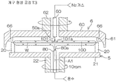
차단 부재(6)는, 차단 부재(6)의 환상부(61)의 내주면으로부터 하방으로, 또한, 기판(W)의 회전 지름 방향의 안쪽으로 돌출되는 복수의 돌출부(66)를 포함한다.The blocking
도 3은, 도 2의 III-III선에 따른 단면의 모식도이다. 척 핀(20)은, 회전축선(A1) 둘레의 회전 방향으로 등간격을 두고 배치되어 있다. 돌출부(66)는, 회전축선(A1) 둘레의 회전 방향으로 등간격을 두고 배치되어 있다. 돌출부(66)는, 척 핀(20)과 동일 개수로 설치되어 있고, 본 실시 형태에서는 4개이다. 차단 부재(6)와 스핀 베이스(21)를 회전 방향으로 위치 맞춤함으로써, 평면에서 볼 때, 회전 방향에 있어서 서로 이웃하는 척 핀(20)의 사이에 돌출부(66)를 1개씩 배치할 수 있다. 돌출부(66)는, 회전 방향에 있어서 기판(W)의 주연을 따라 연장되어 있다. 평면에서 볼 때, 돌출부(66)는 기판(W)의 주연보다 기판(W)의 외측에 위치되어 있다. 3 is a schematic view of a section taken along the line III-III in Fig. The chuck pins 20 are arranged at regular intervals in the rotation direction around the rotation axis A1. The
도 4는, 돌출부(66)의 주변의 모식도이며, 차단 부재(6)가 하부 위치에 있는 상태를 나타내고 있다. 차단 부재(6)가 하부 위치에 있는 상태에서, 돌출부(66)는, 기판(W)의 주연에 기판(W)의 회전 지름 방향의 바깥쪽으로부터 대향한다. 돌출부(66)의 내주면(66a)은, 차단 부재(6)가 하부 위치에 있는 상태에서, 기판(W)의 주연에 기판(W)의 회전 지름 방향의 바깥쪽으로부터 대향하는 근접 대향면으로서 기능한다. 차단 부재(6)가 하부 위치에 있는 상태에서, 돌출부(66)의 내주면(66a)과 기판(W)의 주연 사이에는, 간극(G1)이 형성되어 있다. 차단 부재(6)가 하부 위치에 있는 상태에서, 차단 부재(6)의 돌출부(66)는, 기판(W)의 주연(Wa)에 있어서 척 핀(20)에 의해 유지된 부분(Wb)(도 3 참조)과는 다른 부분(Wc)에 근접해 있다. 차단 부재(6)가 상부 위치에 있는 상태(도 2에 나타내는 상태)에서는, 차단 부재(6)가 기판(W)의 상방으로 퇴피되어 있기 때문에, 돌출부(66)는, 기판 회전 지름 방향의 바깥쪽으로부터 기판(W)에 대향해 있지 않다.Fig. 4 is a schematic view of the periphery of the projecting
이와 같이, 차단 부재(6)의 돌출부(66)는, 기판(W)의 주연에 근접 가능한 근접 부재의 일례이다. 차단 부재 승강 유닛(64)은, 근접 부재로서의 돌출부(66)와 기판(W)의 상대 위치를 변경하는 상대 위치 변경 유닛으로서 기능한다.As described above, the projecting
도 5는, 기판 처리 장치(1)의 주요부의 전기적 구성을 설명하기 위한 블럭도이다. 컨트롤러(3)는, 마이크로 컴퓨터를 구비하고 있고, 소정의 프로그램에 따라, 기판 처리 장치(1)에 구비된 제어 대상을 제어한다. 보다 구체적으로는, 컨트롤러(3)는, 프로세서(CPU)(3A)와, 제어 프로그램이 저장된 메모리(3B)를 포함하고, 프로세서(3A)가 프로그램을 실행함으로써, 기판 처리를 위한 여러가지 제어를 실행하도록 구성되어 있다. 특히, 컨트롤러(3)는, 반송 로봇(IR, CR), 노즐 이동 유닛(35, 45, 55), 전동 모터(23), 차단 부재 승강 유닛(64), 차단 부재 회전 유닛(65), 척 개폐 유닛(25) 및 밸브류(32, 42, 52, 72, 82) 등의 동작을 제어한다. 5 is a block diagram for explaining an electrical configuration of a main portion of the
도 6은, 기판 처리 장치(1)에 의한 기판 처리의 일례를 설명하기 위한 흐름도이며, 주로, 컨트롤러(3)가 프로그램을 실행함으로써 실현되는 처리가 표시되어 있다. 기판 처리 장치(1)에 의한 기판 처리에서는, 예를 들면, 도 6에 나타내는 바와 같이, 기판 반입(S1), 약액 처리(S2), DIW 린스 처리(S3), 유기용제 처리(S4), 건조 처리(S5) 및 기판 반출(S6)이 이 순서대로 실행된다.6 is a flowchart for explaining an example of the substrate processing by the
기판 처리에서는, 우선, 미처리의 기판(W)이, 반송 로봇(IR, CR)에 의해 캐리어(C)로부터 처리 유닛(2)에 반입되고, 스핀 척(5)에 건네진다(S1). 이 후, 기판(W)은, 반송 로봇(CR)에 의해 반출될 때까지, 스핀 베이스(21)의 상면으로부터 상방으로 간격을 두고 수평하게 유지된다(기판 유지 공정). 기판 유지 공정에 있어서, 척 개폐 유닛(25)이, 척 핀(20)에 기판(W)의 주연을 유지시킨다.In the substrate processing, first, the unprocessed substrate W is carried into the
다음에, 반송 로봇(CR)이 처리 유닛(2) 밖으로 퇴피한 후, 약액 처리(S2)가 개시된다.Next, after the transport robot CR retreats out of the
전동 모터(23)는, 스핀 베이스(21)를 회전시킨다. 이로 인해, 척 핀(20)에 수평하게 유지된 기판(W)이 회전한다(기판 회전 공정). 그 한편, 약액 노즐 이동 유닛(35)은, 약액 노즐(30)을 기판(W)의 상방의 약액 처리 위치에 배치한다. 약액 노즐(30)이 약액 처리 위치에 위치할 때, 약액 노즐(30)로부터 토출되는 약액은, 기판(W)의 상면의 회전 중심 위치에 착액한다.The
그리고, 약액 공급 밸브(32)가 열린다. 이로 인해, 회전 상태의 기판(W)의 상면을 향해, 약액 노즐(30)로부터 약액이 토출(공급)된다. 공급된 약액은 원심력에 의해 기판(W)의 상면의 전체에 널리 퍼진다. 이로 인해, 기판(W)의 상면이 약액에 의해 처리된다.Then, the chemical
일정시간의 약액 처리 후, DIW 린스 처리(S3)가 실행된다. DIW 린스 처리(S3)에서는, 기판(W) 상의 약액을 DIW로 치환함으로써, 기판(W) 상으로부터 약액이 배제된다. After the chemical liquid treatment for a predetermined time, the DIW rinsing process (S3) is executed. In the DIW rinsing process (S3), the chemical liquid on the substrate (W) is replaced with DIW, and the chemical liquid is removed from the substrate (W).
우선, 린스액 노즐 이동 유닛(45)이, 린스액 노즐(40)을 기판(W)의 상방의 린스액 처리 위치에 배치한다. 린스액 노즐(40)이 린스액 처리 위치에 위치할 때, 린스액 노즐(40)로부터 토출되는 린스액은, 기판(W)의 상면의 회전 중심 위치에 착액한다.First, the rinsing liquid
그리고, 약액 공급 밸브(32)가 닫히고, 린스액 공급 밸브(42)가 열린다. 이로 인해, 린스액 노즐(40)로부터 기판(W)의 상면을 향해 린스액이 공급(토출)된다(처리액 공급 공정). 린스액 노즐(40)로부터 토출된 린스액은, 기판(W)의 상면의 중앙 영역에 착액한다. 기판(W) 상에 공급된 DIW는 원심력에 의해 기판(W)의 상면의 전체에 널리 퍼진다. 이 DIW에 의해 기판(W) 상의 약액이 씻겨나간다. 이 동안에, 약액 노즐 이동 유닛(35)이, 약액 노즐(30)을 기판(W)의 상방으로부터 퇴피 위치로 이동시킨다.Then, the chemical
일정시간의 DIW 린스 처리 후, 기판(W)을 건조시키는 유기용제 처리(S4)가 행해진다. 구체적으로는, 유기용제 노즐 이동 유닛(75)이, 유기용제 노즐(70)을 유기용제 처리 위치로 이동시킨다. 유기용제 노즐(70)이 유기용제 처리 위치에 위치할 때, 유기용제 노즐(70)로부터 토출되는 유기용제는, 기판(W)의 상면의 회전 중심 위치에 착액한다.After the DIW rinsing treatment for a predetermined period of time, an organic solvent treatment (S4) for drying the substrate W is performed. Specifically, the organic solvent
그리고, 린스액 공급 밸브(42)가 닫히고, 유기용제 밸브(72)가 열린다. 유기용제 노즐(70)로부터 공급(토출)된 IPA 등의 유기용제는, 기판(W)의 상면의 중앙 영역에 착액한다. 기판(W) 상에 공급된 유기용제는 원심력에 의해 기판(W)의 상면의 전체에 널리 퍼진다. 이 유기용제에 의해 기판(W) 상의 린스액이 치환된다(치환 공정). 이전에, 린스액 노즐 이동 유닛(45)이 린스액 노즐(40)을 기판(W)의 상방으로부터 퇴피 위치로 이동시킨다.Then, the rinsing
그리고, 기판(W)의 상면에 대한 유기용제의 공급을 계속함으로써, 기판(W)의 상면에 유기용제의 액막이 형성된다(액막 형성 공정). 그 후, 가열 유체 노즐(80)로부터 공급되는 가열 유체로 기판(W)을 가열함으로써, 유기용제의 액막의 중앙 영역에 개구가 형성된다(개구 형성 공정). 그 후, 이 개구를 확대시킴으로써(개구 확대 공정), 기판(W)의 상면으로부터 유기용제가 배제된다(확대 배제 공정).Then, by continuing the supply of the organic solvent to the upper surface of the substrate W, a liquid film of the organic solvent is formed on the upper surface of the substrate W (liquid film forming step). Thereafter, by heating the substrate W with the heating fluid supplied from the
일정시간의 유기용제 처리(S4) 후, 건조 처리(S5)가 행해진다. 구체적으로는, 전동 모터(23)가 약액 처리(S2) 및 린스액 처리(S3)에 있어서의 기판(W)의 회전 속도보다 빠른 고회전 속도(예를 들면 3000rpm)로 기판(W)을 회전시킨다. 이로 인해, 큰 원심력이 기판(W)의 상면의 유기용제에 작용하여, 기판(W)의 상면의 유기용제가 기판(W)의 주위로 떨쳐내어진다. 이와 같이 하여, 기판(W)으로부터 린스액이 제거되고, 기판(W)이 건조된다. 그리고, 기판(W)의 고속 회전이 개시되고 나서 소정 시간이 경과하면, 전동 모터(23)가, 스핀 베이스(21)에 의한 기판(W)의 회전을 정지시킨다.After the organic solvent treatment (S4) for a predetermined period of time, the drying treatment (S5) is performed. Specifically, the
그 후, 반송 로봇(CR)이 처리 유닛(2)에 진입하여, 스핀 척(5)으로부터 처리가 끝난 기판(W)을 건져 내어, 처리 유닛(2) 밖으로 반출한다(S6). 그 기판(W)은, 반송 로봇(CR)으로부터 반송 로봇(IR)으로 건네지고, 반송 로봇(IR)에 의해, 캐리어(C)에 수납된다.Thereafter, the transfer robot CR enters the
다음에, 유기용제 처리(도 6의 S4)의 상세에 대하여 설명한다.Next, details of the organic solvent treatment (S4 in Fig. 6) will be described.
도 7은, 상기 기판 처리의 유기용제 처리의 일례를 설명하기 위한 흐름도이다. 도 8a~도 8e는, 유기용제 처리(도 6의 S4)의 모습을 설명하기 위한 모식적인 단면도이다. 도 7에 나타내는 바와 같이, 유기용제 처리에서는, 치환 공정(T1), 액막 형성 공정(T2), 개구 형성 공정(T3), 확대 배제 공정(T4)이 이 순서로 실행된다.7 is a flowchart for explaining an example of the organic solvent treatment in the substrate treatment. 8A to 8E are schematic sectional views for explaining the state of the organic solvent treatment (S4 in FIG. 6). As shown in Fig. 7, in the organic solvent treatment, the replacement step (T1), the liquid film forming step (T2), the opening forming step (T3) and the enlargement elimination step (T4) are executed in this order.
도 8a를 참조하여, 치환 공정(T1)에서는, 유기용제 노즐 이동 유닛(75)이, 유기용제 노즐(70)을 유기용제 처리 위치로 이동시킨다. 그리고, 유기용제 밸브(72)를 열고, IPA 등의 유기용제를 기판(W)의 상면에 공급한다. 이로 인해, 기판(W)의 상면의 DIW 등의 린스액이 유기용제에 의해 치환된다.Referring to FIG. 8A, in the replacement step (T1), the organic solvent
치환 공정(T1)에 있어서, 가열 유체 밸브(82)가 열리고, 기판(W)의 하면의 중앙 영역에 온수 등의 가열 유체가 공급된다. 이로 인해, 기판(W)의 하면의 전체에 가열 유체가 널리 퍼지고, 기판(W)이 가열 유체에 의해 가열된다. 가열 유체의 온도는, 예를 들면, 80℃~85℃이다. 그 때문에, 기판(W)의 중앙 영역의 온도가 77℃~82℃에 이른다. 기판(W)의 하면 중심에 도달한 직후부터 기판(W)과 가열 유체의 열교환이 시작되므로, 가열 유체가 기판(W)의 외주에 이르기까지 가열 유체의 열량이 기판(W)에 빼앗긴다. 그 때문에, 기판(W)의 외주의 온도는, 71℃ 정도가 된다. 따라서, 기판(W) 상의 유기용제의 온도는, IPA의 비점(82.6℃)보다 낮다.In the replacement step (T1), the heating fluid valve (82) is opened, and a heating fluid such as hot water is supplied to the central area of the lower surface of the substrate (W). As a result, the heating fluid spreads over the entire lower surface of the substrate W, and the substrate W is heated by the heating fluid. The temperature of the heating fluid is, for example, 80 ° C to 85 ° C. Therefore, the temperature of the central region of the substrate W reaches 77 占 폚 to 82 占 폚. Since the heat exchange between the substrate W and the heating fluid starts immediately after reaching the center of the lower surface of the substrate W, the amount of heat of the heating fluid is lost to the substrate W until the heating fluid reaches the outer periphery of the substrate W. Therefore, the temperature of the outer periphery of the substrate W is about 71 캜. Therefore, the temperature of the organic solvent on the substrate W is lower than the boiling point (82.6 DEG C) of IPA.
치환 공정(T1)에서는, 차단 부재 승강 유닛(64)은, 차단 부재(6)를 상부 위치에 배치하고 있다. 또, 치환 공정(T1)에서는, 전동 모터(23)는, 스핀 베이스(21)를 예를 들면 300rpm으로 회전시킨다. 이때, 차단 부재 회전 유닛(65)은, 차단 부재(6)를 스핀 베이스(21)와 동기 회전시켜도 된다. 동기 회전은, 같은 방향으로 같은 회전 속도로 회전하는 것을 의미한다.In the replacement step (T1), the blocking member lifting unit (64) places the blocking member (6) at the upper position. In the replacement step (T1), the
도 8b를 참조하여, 액막 형성 공정(T2)에서는, 기판(W) 상의 린스액이 유기용제에 의해 치환된 후, 유기용제 노즐(70)로부터 기판(W)의 상면에 대한 유기용제의 공급이 계속된다. 이로 인해, 기판(W)의 상면에 유기용제의 액막(100)이 형성된다. 액막 형성 공정(T2)에서 형성되는 액막(100)의 두께는, 예를 들면, 1㎜ 정도이다. 8B, in the liquid film forming process (T2), after the rinsing liquid on the substrate W is replaced by the organic solvent, the supply of the organic solvent from the organic
액막 형성 공정(T2)에서는, 기판(W)의 가열이 약해진다. 자세히는, 기판(W)의 상면에 대한 유기용제의 공급을 계속시키는 한편으로, 가열 유체 밸브(82)가 닫힌다. 이로 인해, 기판(W)의 하면의 중심에 대한 가열 유체의 공급이 정지된다. 치환 공정(T1)에 있어서 가열 유체를 공급하고 있는 동안의 기판(W) 상의 유기용제의 온도가, 유기용제의 비점(IPA의 비점:82.6℃)보다 낮기 때문에, 가열 유체의 공급을 정지한 후의 기판(W) 상의 유기용제의 온도는, 유기용제의 비점보다 낮은 온도로 유지되어 있다. 즉, 액막 형성 공정(T2)은, 기판(W) 상의 유기용제의 온도를 유기용제의 비점 이하로 유지한 상태로, 기판(W)의 상면에 액막(100)을 형성하는 공정을 포함한다.In the liquid film forming step (T2), the heating of the substrate W is weakened. More specifically, while the supply of the organic solvent to the upper surface of the substrate W is continued, the
액막 형성 공정(T2)에서는, 전동 모터(23)가, 스핀 베이스(21)의 회전을 감속시키고, 기판(W)의 회전을 치환 공정(T1)보다 감속시킨다. 자세히는, 전동 모터(23)는, 기판(W) 상의 액막(100)이 기판(W) 상에서 분열하지 않는 정도(기판(W) 상에 액막(100)이 유지되는 정도)의 속도로 기판(W)을 회전시킨다. 이 때의 기판(W)의 회전 속도를 액막 유지 속도라고 한다. 액막 유지 속도는, 예를 들면, 10rpm이다. 액막 유지 속도는, 액막(100)이 기판(W) 상에서 분열하지 않는 속도 범위에서 일정하게 유지되어도 된다. 또, 액막 유지 속도는, 액막(100)이 기판(W) 상에서 분열하지 않는 속도 범위에서 변경되어도 된다. 차단 부재(6)는, 스핀 베이스(21)와 동기 회전하고 있다.In the liquid film forming process (T2), the electric motor (23) decelerates the rotation of the spin base (21) and decelerates the rotation of the substrate (W). More specifically, the
도 8c를 참조하여, 개구 형성 공정(T3)에서는, 기판(W)의 상면의 중앙 영역에 대한 유기용제의 공급을 정지하는 한편으로, 기판(W)의 가열을 강하게 한다. 이로 인해, 액막(100)의 중앙 영역에 개구(101)가 형성된다.8C, in the opening forming step T3, the supply of the organic solvent to the central region of the upper surface of the substrate W is stopped, while the heating of the substrate W is strengthened. As a result, the
자세히는, 유기용제 밸브(72)가 닫힘으로써, 유기용제 노즐(70)로부터 기판(W)의 상면에 대한 유기용제의 공급이 정지된다. 또, 가열 유체 밸브(82)가 열림으로써, 기판(W)의 하면의 중심에 대한 가열 유체의 공급이 재개된다. 이로 인해, 기판(W)의 중앙 영역이 따뜻해지고, 액막(100)의 중앙 영역의 온도가, 액막 형성 공정(T2)에 있어서의 액막(100)의 온도보다 높아진다. 그로 인해, 기판(W)의 중앙 영역의 유기용제의 표면장력이 저하하고, 기판(W)의 중앙 영역에 있어서만 액막(100)이 얇아진다(도 8c의 2점 쇄선 참조). 액막(100)의 중앙 영역의 유기용제의 온도가 상승하기 때문에, 유기용제의 증발이 촉진되고, 이윽고, 액막(100)의 중앙 영역에 개구(101)가 형성된다.More specifically, the supply of the organic solvent to the upper surface of the substrate W from the organic
개구 형성 공정(T3)에서는, 기체 밸브(52)가 열림으로써, 액막(100)의 중앙 영역을 향해 질소 가스 등의 기체가 분사된다. 그 때문에, 개구(101)의 형성은, 기판(W)의 중심에 대한 기체의 공급에 의해 보조된다. 개구 형성 공정(T3)에 있어서도, 액막 형성 공정(T2)과 마찬가지로, 스핀 베이스(21)(기판(W))는, 액막 유지 속도로 회전되어 있고, 차단 부재(6)는, 스핀 베이스(21)와 동기 회전하고 있다.In the opening forming step T3, the
개구 형성 공정(T3)에서는, 기판(W)에 대한 가열의 재개, 및, 기판(W)의 상면에 대한 기체의 분사 전에, 유기용제 노즐 이동 유닛(75)이, 유기용제 노즐(70)을 퇴피 위치로 이동시킨다. 그리고, 개구 형성 공정(T3)에서는, 기판(W)에 대한 가열의 재개, 및, 기판(W)의 상면에 대한 기체의 분사 전에, 차단 부재 승강 유닛(64)이, 차단 부재(6)를 상부 위치와 하부 위치 사이의 차단 위치로 이동시킨다. 차단 부재(6)가 차단 위치에 위치하는 상태에서, 환상부(61)에 있어서 돌출부(66)보다 하측의 부분이, 기판 회전 지름 방향의 바깥쪽으로부터 기판(W)에 대향해 있다. 이로 인해, 차단 부재(6)의 대향부(60)와 기판(W)의 상면 사이의 분위기가, 외부의 분위기로부터 차단된다.In the opening forming step T3, before the heating of the substrate W is resumed and the gas is jetted onto the upper surface of the substrate W, the organic solvent
도 8d 및 도 8e를 참조하여, 확대 배제 공정(T4)에서는, 구체적으로는, 기판(W)의 중앙 영역에 대한 가열을 계속함으로써, 기판(W)의 주연을 향해 개구(101)를 확대시키고(개구 확대 공정), 그로 인해, 기판(W)의 상면으로부터 액막(100)이 배제된다. 도 8e는, 도 8d보다 나중의 상태를 나타내고 있고, 개구(101)의 주연(101a)이 기판(W)의 주연에 도달한 상태를 나타내고 있다. 8D and 8E, in the enlargement elimination step T4, specifically, the heating of the central region of the substrate W is continued to enlarge the
확대 배제 공정(T4)에서는, 기판(W)의 중앙 영역을 향한 질소 가스 등의 기체의 분사가 계속된다. 그 때문에, 개구(101)의 확대가, 기판(W)의 중심에 대한 기체의 공급에 의해 보조된다. 확대 배제 공정(T4)에 있어서도, 액막 형성 공정(T2) 및 개구 형성 공정(T3)과 마찬가지로, 스핀 베이스(21)(기판(W))는, 액막 유지 속도로 회전되어 있다.In the enlargement elimination step (T4), gas such as nitrogen gas is continuously injected toward the central region of the substrate (W). Therefore, the enlargement of the
자세히는, 확대 배제 공정(T4)에서는, 차단 부재 승강 유닛(64)이, 차단 부재(6)를 차단 위치로부터 하부 위치로 이동시킨다. 차단 부재(6)가 차단 위치로부터 하부 위치로 이동되기 전에, 차단 부재 회전 유닛(65)이, 돌출부(66)와 척 핀(20)이 평면에서 볼 때 겹치지 않도록, 회전축선(A1) 둘레의 회전 방향에 있어서의 차단 부재(6)와 스핀 베이스(21)의 위상을 조정한다. 돌출부(66)와 척 핀(20)이 평면에서 볼 때 겹치지 않도록 차단 부재(6)와 스핀 베이스(21)가 동기 회전하고 있는 경우, 회전축선(A1) 둘레의 회전 방향에 있어서의 차단 부재(6)와 스핀 베이스(21)의 위상의 조정을 생략할 수 있다.More specifically, in the enlargement elimination step T4, the blocking
차단 부재(6)가 하부 위치로 이동됨으로써, 차단 부재(6)의 돌출부(66)가 기판(W)의 주연에 상방으로부터 접근한다. 도 8d에 나타내는 바와 같이, 차단 부재(6)는, 개구(101)의 주연(101a)이 기판(W)의 주연(Wa) 부근에 도달하기 전(도 8e 상태가 되기 전)에 하부 위치로 이동하는 것이 바람직하다. 이로 인해, 차단 부재(6)의 돌출부(66)와 기판(W)의 주연(Wa) 사이에 간극(G1)(도 4 참조)이 형성되도록 차단 부재(6)의 돌출부(66)가 기판(W)의 주연(Wa)에 근접하고, 또한, 돌출부(66)가 액막(100)에 접촉한다(액막 접촉 공정). 이 상태에서, 기판(W)의 주연에 있어서 척 핀(20)에 의해 유지된 부분(Wb)과는 다른 부분(Wc)에, 돌출부(66)가 근접해 있다(도 3 및 후술하는 도 10b 참조). 액막 접촉 공정은, 개구 형성 공정(T3)의 개시 후에 실행된다. 자세히는, 액막 접촉 공정은, 확대 배제 공정(T4)과 병행하여 실행된다.The protruding
도 9a는, 확대 배제 공정(T4)에 있어서의 개구(101)의 주연(101a) 부근을 모식적으로 나타낸 도면이다. 도 9b는, 회전하고 있지 않은 상태의 기판(W) 상에 적하된 유기용제의 액적 A 부근을 모식적으로 나타낸 도면이다. 9A is a diagram schematically showing the vicinity of the
도 9a에 나타내는 바와 같이, 확대 배제 공정(T4)에서는, 기판(W)의 가열에 의해, 개구(101)의 주연(101a)에 위치하는 액막(100)의 기액 계면(100a)에 있어서, 기판(W)의 상면으로부터 멀어지는 방향의 대류(102)가 액막(100) 중에 발생하고 있다. 이 대류(102)는, 액막(100) 중에 있어서, 기판(W)의 상면에 가까운 부분일수록 액체의 온도가 높은 것에 따라 발생한다. 대류(102)는, 기판(W)의 상면으로부터 멀어지는 방향을 따라서 발생하고, 또한 기액 계면(100a)을 따르는 흐름을 형성하므로, 개구(101)가 확대하는 방향을 향하는 액막(100)의 자발적인 이동을 발생시킨다.
확대 배제 공정(T4)에 있어서, 개구(101)의 주연(101a)에 위치하는 액막(100)의 기액 계면(100a)이, 기판(W)의 상면에 대해서, 유기용제의 기판(W)의 상면에 대한 접촉각 θ2(도 9b 참조)보다 큰 각도 θ1로 접해 있다. 대류(102)에 기인하는 액막(100)의 자발적 이동이 발생하고 있을 때, 이러한 상태가 된다. 접촉각 θ2는, 유기용제의 액적 A의 기액 계면과 기판(W)의 상면 사이에서 액막(100)의 내부에 형성되는 각도이다. 각도 θ1은, 접선(101b)과 기판(W)의 상면 사이에서 액막(100)의 내부에 형성되는 각도이다. 접선(101b)은, 기액 계면(100a)에 직교하는 평면 상에서 당해 기액 계면(100a)이 형성하는 곡선에 있어서 기판(W)의 상면과의 교점을 접점으로 하여 그은 접선이다. 개구(101)의 주연(101a)보다 외측이란, 주연(101a)에 대해서 회전 중심 위치와는 반대측을 말한다. 각도 θ1은, 45도 이상인 것이 바람직하다.
기판(W)을 회전시킴으로써 액막(100)에 원심력이 작용하고 있거나, 개구(101) 내에 기체를 공급함으로써, 그 기체에 의한 분사력이 액막(100)의 개구(101)의 주연(101a)에 작용하고 있거나 해도 된다. 이러한 경우라도, 개구(101)의 주연(101a)에 있어서의 액막(100)의 기액 계면(100a)이, 기판(W)의 상면에 대해서, 유기용제의 기판(W)에 대한 접촉각 θ2보다 큰 각도 θ1(예를 들면 45도 이상의 각도)로 접하고 있는 것이 바람직하다. 그러면, 액막(100)의 이동(개구(101)의 확대)에 대한 지배적인 메커니즘은, 액막(100) 중의 대류(102)에 기인하는 자발적 이동이라고 할 수 있다.A centrifugal force acts on the
또, 액막(100)의 두께는, 1㎜ 정도로 충분히 두껍기 때문에, 기판(W)의 상면과 액막(100)의 상면 사이의 온도차가 커지기 쉽기 때문에, 액막(100) 내에서 대류(102)가 일어나기 쉽다. 액막(100) 내에 있어서, 기판(W)의 상면 부근의 유기용제의 온도와 액막(100)의 표면 부근의 유기용제의 온도의 차는, 30℃~35℃이면, 대류(102)가 한층 더 일어나기 쉽다.The temperature difference between the upper surface of the substrate W and the upper surface of the
확대 배제 공정(T4)에 있어서, 액막(100)에 작용하는 원심력에 의한 액막(100)의 이동 속도와 질소 가스 등의 기체의 분사에 의한 액막(100)의 이동 속도의 합보다 액막(100) 중의 대류(102)에 의한 액막(100)의 이동 속도가 고속이 되도록, 가열 유체 밸브(82) 및 전동 모터(23)를 제어하여, 기판(W)의 가열 및 회전을 제어하는 것이 바람직하다. 액막(100)의 이동 속도란, 개구(101)의 주연(101a)이 기판(W)의 회전 중심 위치로부터 멀어지는 방향을 향하는 속도이다.The
제1 실시 형태에 의하면, 액막 형성 공정(T2)에 있어서 기판(W)의 상면에 IPA 등의 유기용제의 액막(100)이 형성되고, 개구 형성 공정(T3)에 있어서 액막(100)의 중앙 영역에 개구(101)가 형성된다. 그 후, 확대 배제 공정(T4)에 있어서 기판(W)의 주연을 향해 개구(101)가 넓혀짐으로써, 액막(100)이 기판(W)의 상면으로부터 배제된다. 개구 형성 공정(T3)의 개시 후에, 차단 부재(6)의 돌출부(66)가, 기판(W)의 주연(Wa)에 근접하고, 또한, 액막(100)에 접촉한다. 그 때문에, 개구(101)의 확대에 따라 개구(101)의 주연(101a)이 기판(W)의 주연(Wa)에 가까워지는 것에 기인하여, 기판(W)의 주연(Wa) 부근에 위치하는 유기용제를 기판(W) 밖으로 밀어내는 힘이 작아져도, 기판(W)의 주연(Wa) 부근의 유기용제가, 돌출부(66)를 타고 기판(W) 밖으로 배출된다(도 10a 참조). 따라서, 액막(100)을 분열시키지 않고, 덩어리 상태의 액막(100)을 기판(W)의 상면으로부터 배제할 수 있다. 따라서, 기판(W)의 상면에 유기용제의 액적을 남기지 않고, 기판(W) 상의 유기용제를 양호하게 배제할 수 있다.The
제1 실시 형태에 의하면, 액막 접촉 공정이, 확대 배제 공정(T4)과 병행하여 실행된다. 이로 인해, 확대 배제 공정(T4)에 있어서, 기판(W)의 주연(Wa) 부근의 유기용제가, 돌출부(66)를 타고 기판(W) 밖으로 배출된다. 그 때문에, 개구(101)의 확대를 정지시키지 않고, 기판(W)의 상면의 유기용제를 효율적으로 배제할 수 있다.According to the first embodiment, the liquid film contact process is executed in parallel with the enlargement removal process (T4). The organic solvent in the vicinity of the periphery Wa of the substrate W is discharged to the outside of the substrate W on the protruding
제1 실시 형태에 의하면, 액막 접촉 공정에 있어서, 차단 부재(6)의 돌출부(66)와 기판(W)의 주연(Wa) 사이에 간극(G1)이 형성되도록, 차단 부재(6)의 돌출부(66)를 기판(W)의 주연(Wa)에 근접시킨다. 이로 인해, 기판(W)의 주연(Wa) 부근에 위치하는 유기용제가, 간극(G1)을 통과할 수 있다. 그 때문에, 도 10b에 나타내는 바와 같이, 액막 접촉 공정에서는, 유기용제는, 돌출부(66)의 둘레 방향 단면(66b)을 타고 기판(W) 밖으로 배제될 뿐만 아니라, 돌출부(66)와 기판(W)의 주연(Wa) 사이의 간극(G1)도 통과하여 기판(W) 밖으로 배제된다. 따라서, 기판(W)의 주연(Wa)과 돌출부(66)가 맞닿아 있는 구성과 비교하여, 기판(W)의 주연(Wa) 부근에 위치하는 유기용제를 효율적으로 기판(W) 밖으로 배제할 수 있다.The gap G1 is formed between the projecting
제1 실시 형태에 의하면, 스핀 베이스(21)의 상면에 설치된 척 핀(20)이 기판(W)의 주연(Wa)을 유지한다. 그리고, 액막 접촉 공정에 있어서, 기판(W)의 주연(Wa)에 있어서 척 핀(20)에 의해 유지된 부분(Wb)과는 다른 부분(Wc)에 돌출부(66)가 근접한다.According to the first embodiment, the
도 10b를 참조하여, 기판(W)의 주연 부근에 위치하는 유기용제는, 돌출부(66)를 타고 기판(W) 밖으로 배제될 뿐만 아니라, 기판(W)의 주연(Wa)을 유지하는 척 핀(20)도 타고 기판(W) 밖으로 배제된다. 기판(W)의 주연(Wa)에 있어서 척 핀(20)에 의해 유지된 부분(Wb)과는 다른 부분(Wc)에, 돌출부(66)가 근접됨으로써, 척 핀(20)과 돌출부(66)의 양쪽에 의해 기판(W)의 주연(Wa) 부근에 위치하는 유기용제가 기판(W) 밖으로 배제된다. 따라서, 기판(W)의 주연(Wa) 부근에 위치하는 유기용제를 기판(W) 밖으로 배제할 수 있다.10B, the organic solvent located near the periphery of the substrate W is not only ejected out of the substrate W while riding on the projecting
제1 실시 형태에 의하면, 기판(W)의 상면에 대향하여 기판(W)과의 사이의 분위기를 주위의 분위기로부터 차단하는 차단 부재(6)에 돌출부(66)(근접 부재)가 설치되어 있다. 그리고, 액막 접촉 공정에 있어서, 기판(W)의 주연(Wa)에 차단 부재(6)의 돌출부(66)가 상방으로부터 접근한다. 기판(W)의 주연(Wa)에 차단 부재(6)의 돌출부(66)를 상방으로부터 접근시킴으로써, 차단 부재(6)의 돌출부(66)를 액막(100)에 접촉시킬 수 있다. 차단 부재(6)가 기판(W)과 차단 부재(6)의 대향면(60a) 사이의 분위기를 주위의 분위기로부터 차단하기 때문에, 주위의 분위기에 의한 액막(100) 및 기판(W)의 오염을 억제 또는 방지할 수 있다. According to the first embodiment, the protruding portion 66 (close-up member) is provided on the blocking
제1 실시 형태에 의하면, 액막 형성 공정(T2)에서는, 기판(W) 상의 IPA 등의 유기용제의 온도를 유기용제의 비점(예를 들면, 82.6℃) 이하로 유지한 상태에서, 기판(W)의 상면에 액막(100)이 형성된다. 이로 인해, 기판(W) 상의 유기용제의 온도가 비점 이하로 유지되므로, 유기용제의 증발을 억제할 수 있다. 따라서, 유기용제의 증발에 기인하는 액막(100)의 분열을 억제 또는 방지할 수 있다. 따라서, 덩어리 상태의 액막(100)을 기판(W) 밖으로 배제할 수 있으므로, 기판(W)의 상면에 유기용제의 액적을 남기지 않고, 기판(W) 상의 유기용제를 양호하게 배제할 수 있다.According to the first embodiment, in the liquid film forming step (T2), the temperature of the organic solvent such as IPA on the substrate W is maintained at the boiling point of the organic solvent (for example, 82.6 DEG C) The
제1 실시 형태에 의하면, 개구 형성 공정(T3)에 있어서, 액막(100)의 중앙 영역의 온도를, 액막 형성 공정(T2)에 있어서의 액막(100)의 온도보다 높게 함으로써, 액막(100)에 개구(101)가 형성된다. 이로 인해, 유기용제의 액막(100)의 중앙 영역에 개구(101)가 형성된다. 그 때문에, 기판(W)의 중앙 영역으로부터 기판(W)의 주연(Wa)을 향해, 개구(101)를 균등하게 넓힐 수 있다. 따라서, 기판(W)의 상면으로부터 유기용제를 편차없이 배제할 수 있다. The temperature of the central region of the
제1 실시 형태에 의하면, 확대 배제 공정(T4)에서는, 개구(101)의 주연(101a)에 위치하는 액막(100)의 기액 계면(100a)에 있어서, 기판(W)으로부터 멀어지는 방향의 대류(102)가 발생하도록 기판(W)이 가열된다. 그로 인해, 개구(101)가 기판(W)의 주연(Wa)을 향해 넓혀진다. 이로 인해, 액막(100)의 중앙 영역에 형성된 개구(101)의 주연(101a)에 있어서의 액막(100)의 기액 계면(100a)에 있어서, 기판(W)으로부터 멀어지는 방향의 대류(102)가 발생한다. 이 대류(102)는, 개구(101)를 넓히는 방향을 향하는 자발적인 이동을 발생시키고, 그로 인해, 개구(101)가 확대된다. 그 때문에, 덩어리 상태의 액막(100)을 분열시키지 않고 기판(W) 상으로부터 유기용제를 한층 더 양호하게 배제할 수 있다.
또한, 제1 실시 형태에 의하면, 치환 공정(T1)에서는, 기판(W)의 회전에 의해 발생하는 원심력에 의해 린스액을 배제하면서 유기용제가 기판(W)의 상면에 공급된다. 그 때문에, 기판(W) 상의 린스액을 유기용제로 효율적으로 치환시킬 수 있다. 또, 액막 형성 공정(T2)에서는, 기판(W)의 회전을 감속시킴으로써 원심력을 저감시킬 수 있다. 이로 인해, 기판(W)으로부터 배제되는 유기용제의 양이 저감되므로 액막(100)을 양호하게 형성할 수 있다. 또, 개구 형성 공정(T3) 및 확대 배제 공정(T4)에 있어서는, 기판(W)을 치환 공정(T1)에 있어서의 회전 속도보다 저속도로 회전시킴으로써, 가열에 기인하는 액막(100)의 자발적인 이동이 지배적인 상태가 되고, 적당한 원심력에 의해, 액막(100)의 자발적인 이동을 보조할 수 있다.According to the first embodiment, in the replacement step (T1), the organic solvent is supplied to the upper surface of the substrate W while eliminating the rinsing liquid by the centrifugal force generated by the rotation of the substrate W. Therefore, the rinsing liquid on the substrate W can be efficiently replaced with an organic solvent. In the liquid film forming step (T2), the centrifugal force can be reduced by decelerating the rotation of the substrate (W). As a result, the amount of the organic solvent removed from the substrate W is reduced, so that the
또한, 제1 실시 형태에 의하면, 액막(100)에 작용하는 원심력에 의한 액막(100)의 이동 속도보다 대류(102)에 의한 액막(100)의 자발적 이동 속도가 고속이기 때문에, 원심력에 의해 기판(W)으로부터 배제되는 유기용제의 양을 억제할 수 있다. 그로 인해, 액막(100)이 기판(W) 상에서 분열하는 것을 한층 더 억제할 수 있다. 따라서, 기판(W) 상의 유기용제를 한층 더 양호하게 배제할 수 있다.According to the first embodiment, since the spontaneous moving speed of the
또, 액막(100)이 기판(W) 상에서 분열하지 않는 속도 범위에서 기판(W)이 회전하기 때문에, 원심력에 의해 액막(100)의 이동을 보조하면서, 액괴 상태를 유지하여, 액막(100)을 기판(W) 밖으로 배제할 수 있다.Since the substrate W rotates in the speed range in which the
또, 유기용제 노즐(70)은, 기판(W)보다 온도가 낮은 유기용제를 공급하고 있기 때문에, 기판(W)과 유기용제의 온도차에 의해, 액막(100) 중의 대류(102)가 발생하기 쉬워진다. 보다 구체적으로는, 가열 유체 노즐(80)의 가열 유체의 공급에 의한 가열 위치 부근에 있어서의 기판(W)의 온도보다 유기용제의 온도가 낮은 것이 바람직하다. 그로 인해, 가열 위치 부근에 있어서, 기판(W)으로부터 액막(100)의 상면을 향하는 대류(102)를 발생시키고, 또 촉진시킬 수 있다. 따라서, 기판(W) 상에 있어서의 액막(100)의 자발적 이동에 의해, 액막(100)을 기판(W) 밖으로 효율적으로 배제할 수 있다.Since the organic
또, 기판(W)의 하면의 중심을 향해 가열 유체를 공급함으로써 기판의 중심 부근(중앙 영역)의 액막(100)의 유기용제의 증발을 촉진할 수 있고, 또한 기판(W)의 중앙 영역에 액막(100) 중의 대류(102)의 시작점을 배치할 수 있다. 그로 인해, 기판(W)의 중심, 즉 액막(100)의 중심 위치에 있어서 액막(100)에 개구(101)를 발생시키고, 또한, 그 개구(101)를 외측으로 넓히도록 액막(100)을 이동시켜 액막(100)을 기판(W) 밖으로 배제할 수 있다.By supplying the heating fluid toward the center of the lower surface of the substrate W, evaporation of the organic solvent in the
<제2 실시 형태> ≪ Second Embodiment >
도 11은, 이 발명의 제2 실시 형태에 따른 기판 처리 장치(1P)의 스핀 베이스(21)의 주변을 평면에서 보았을 때의 모식도이다. 도 12는, 기판 처리 장치(1P)에 구비된 처리 유닛(2)의 구성예를 나타내는 모식도이며, 도 11의 XII-XII선을 따른 단면을 나타내고 있다. 도 11 및 도 12에서는, 지금까지 설명한 부재와 같은 부재에는 같은 참조 부호를 부여하고, 그 설명을 생략한다(후술하는 도 13a 및 도 13b도 동일).Fig. 11 is a schematic view showing the periphery of the
도 11 및 도 12를 참조하여, 기판 처리 장치(1P)가 제1 실시 형태에 따른 기판 처리 장치(1)(도 2를 참조)와 주로 다른 점은, 처리 유닛(2)이, 스핀 베이스(21)의 상면에 설치되고 기판(W)의 주연에 근접 가능한 복수의 근접 핀(90)과, 연직 방향을 따라 각 근접 핀(90)을 통과하는 회동축선(A2)의 둘레로 각 근접 핀(90)을 회전시키는 근접 핀 구동 유닛(95)을 포함하는 점이다.11 and 12, the substrate processing apparatus 1P is mainly different from the substrate processing apparatus 1 (see Fig. 2) according to the first embodiment in that the
근접 핀(90)은, 예를 들면 연직 방향으로 연장되는 기둥 형상의 형태를 갖고 있다. 근접 핀(90)은, 평면에서 볼 때 대략 타원 형상이다. 근접 핀(90)은, 회전축선(A1) 둘레의 회전 방향에 있어서 인접하는 척 핀(20)들의 사이에 배치되어 있다. 이 실시 형태에서는, 척 핀(20)은, 기판(W)의 회전 방향에 있어서 90° 간격으로 합계 4개 배치되어 있다. 근접 핀(90)은, 기판(W)의 회전 방향에 있어서 인접하는 척 핀(20)들의 사이에 등간격으로 2개씩 배치되어 있다.The
근접 핀(90)은, 스핀 베이스(21)에 회동 가능하게 지지된 피지지부(91)와, 피지지부(91)와 일체로 설치되고, 피지지부(91)로부터 회동축선(A2)의 회전 지름 방향의 바깥쪽으로 연장되는 연장 설치부(92)를 포함한다. 근접 핀 구동 유닛(95)은 회동축선(A2) 둘레의 회전력을 근접 핀(90)의 피지지부(91)에 부여하는 전동 모터를 포함한다.The
근접 핀(90)이 근접 핀 구동 유닛(95)에 의해 회동축선(A2) 둘레로 회동됨으로써, 근접 핀(90)의 연장 설치부(92)는, 기판(W)의 주연(Wa)에 대해 근접하거나, 기판(W)의 주연(Wa)으로부터 이격하거나 한다. 연장 설치부(92)가 기판(W)의 주연(Wa)에 대해 가장 근접할 때의 근접 핀(90)의 위치(도 11에 2점 쇄선으로 나타내는 근접 핀(90)의 위치)를 근접 위치라고 한다. 연장 설치부(92)가 기판(W)의 주연(Wa)에 대해서 가장 이격할 때의 근접 핀(90)의 위치(도 11에 실선으로 나타내는 근접 핀(90)의 위치)를 이격 위치라고 한다.The
근접 핀(90)이 근접 위치에 위치하는 상태에서, 근접 핀(90)의 연장 설치부(92)와 기판(W)의 주연(Wa) 사이에는, 간극(G2)이 형성되어 있다. 근접 핀(90)이 근접 위치에 있는 상태에서, 근접 핀(90)의 연장 설치부(92)는, 기판(W)의 주연(Wa)에 있어서 척 핀(20)에 의해 유지된 부분(Wb)과는 다른 부분(Wc)에 근접해 있다.A gap G2 is formed between the extending
이와 같이, 근접 핀(90)은, 기판(W)의 주연(Wa)에 근접 가능한 근접 부재의 일례이다. 근접 핀 구동 유닛(95)은, 근접 부재로서의 근접 핀(90)과 기판(W)의 상대 위치를 변경하는 상대 위치 변경 유닛으로서 기능한다.As described above, the
제2 실시 형태에 따른 차단 부재(6)에는, 제1 실시 형태에 따른 차단 부재(6)와는 달리, 환상부(61) 및 돌출부(66)가 설치되어 있지 않다. 제2 실시 형태에 따른 컨트롤러(3)는, 근접 핀 구동 유닛(95)을 제어한다(도 5의 2점 쇄선 참조).The blocking
도 13a 및 도 13b는, 기판 처리 장치(1P)에 의한 기판 처리에 있어서의 유기용제 처리(도 6의 S4)의 모습을 설명하기 위한 모식적인 단면도이다. 도 13b는, 도 13a보다 나중의 상태를 나타내고 있고, 개구(101)의 주연(101a)이 기판(W)의 주연(Wa)에 도달한 상태를 나타내고 있다.13A and 13B are schematic cross-sectional views for explaining the state of the organic solvent treatment (S4 in FIG. 6) in the substrate treatment by the substrate treatment apparatus 1P. Fig. 13B shows a state later than Fig. 13A, and shows a state in which the
제2 실시 형태에 따른 기판 처리 장치(1P)에 의한 기판 처리에서는, 제1 실시 형태에 따른 기판 처리 장치(1)에 의한 기판 처리와 같은 기판 처리가 가능하다. 단, 도 13a 및 도 13b에 나타내는 바와 같이, 확대 배제 공정(T4)에 있어서, 근접 핀 구동 유닛(95)은, 회동축선(A2) 둘레로 근접 핀(90)을 회동시킴으로써, 근접 핀(90)을 기판 회전 지름 방향의 바깥쪽으로부터(기판(W)의 바깥쪽으로부터) 기판(W)의 주연(Wa)에 근접시키고, 또한, 근접 핀(90)(의 연장 설치부(92))을 액막(100)에 접촉시킨다(액막 접촉 공정).In the substrate processing by the substrate processing apparatus 1P according to the second embodiment, substrate processing such as substrate processing by the
그 때문에, 제2 실시 형태에 의하면, 개구(101)의 확대에 따라 개구(101)의 주연(101a)이 기판(W)의 주연(Wa)에 가까워지는 것에 기인하여, 기판(W)의 주연(Wa) 부근에 위치하는 유기용제가 기판(W) 밖으로 밀려나오는 힘이 작아진 경우라도, 기판(W)의 주연(Wa) 부근의 유기용제가, 근접 핀(90)을 타고 기판(W) 밖으로 배출된다(도 13b의 굵은선 화살표 참조). 따라서, 액막(100)을 분열시키지 않고, 덩어리 상태의 액막(100)을 기판(W)의 상면으로부터 배제할 수 있다. 따라서, 기판(W)의 상면에 유기용제의 액적을 남기지 않고, 기판(W) 상의 유기용제를 양호하게 배제할 수 있다.The
제2 실시 형태에 의하면, 액막 접촉 공정에 있어서, 근접 핀(90)의 연장 설치부(92)와 기판(W)의 주연(Wa) 사이에 간극(G2)이 형성되도록, 근접 핀(90)의 연장 설치부(92)를 기판(W)의 주연(Wa)에 근접시킨다. 이로 인해, 기판(W)의 주연(Wa) 부근에 위치하는 유기용제가, 간극(G2)을 통과할 수 있다. 그 때문에, 도 13b에 굵은 선 화살표로 나타내는 바와 같이, 액막 접촉 공정에서는, 유기용제는, 근접 핀(90)을 타고 기판(W) 밖으로 배제될 뿐만 아니라, 연장 설치부(92)와 기판(W)의 주연(Wa) 사이의 간극(G2)도 통과하여 기판(W) 밖으로 배제된다. 따라서, 기판(W)의 주연(Wa)과 연장 설치부(92)가 맞닿아 있는 구성과 비교하여, 기판(W)의 주연(Wa) 부근에 위치하는 유기용제를 효율적으로 기판(W) 밖으로 배제할 수 있다.According to the second embodiment, in the liquid film contacting step, the gap G2 is formed between the extending
제2 실시 형태에 의하면, 스핀 베이스(21)의 상면에 설치된 근접 핀(90)이 근접 부재로서 기능한다. 그리고, 액막 접촉 공정에 있어서, 기판(W)의 회전 지름 방향의 바깥쪽(기판(W)의 바깥쪽)으로부터 근접 핀(90)을 기판(W)의 주연(Wa)에 접근시킨다. 이로 인해, 스핀 베이스(21)에 설치된 근접 핀(90)을 기판(W)의 바깥쪽으로부터 기판(W)의 주연(Wa)에 접근시킨다는 간단한 구성으로 근접 핀(90)을 액막(100)에 접촉시킬 수 있다. 그 때문에, 스핀 베이스(21)와는 독립된 다른 근접 부재를 일부러 설치할 필요가 없다.According to the second embodiment, the
제2 실시 형태에 의하면, 상술한 효과 외에도, 제1 실시 형태와 같은 효과를 나타낸다. According to the second embodiment, in addition to the above-described effects, the same effects as those of the first embodiment can be obtained.
이 발명은, 이상으로 설명한 실시 형태로 한정되는 것이 아니라, 또 다른 형태로 실시할 수 있다.The present invention is not limited to the above-described embodiments, but can be embodied in another form.
예를 들면, 개구 형성 공정(T3)에서는, 기판(W)의 가열에 의해 액막(100)에 개구(101)가 형성되었지만, 기판(W)에 대한 가열을 행하지 않고, 기체의 분사만에 의해 액막(100)에 개구(101)가 형성되어도 된다.For example, in the opening forming process (T3), the
또, 가열 유체 공급 유닛(11)은, 기판(W)의 중앙 영역뿐만 아니라, 기판(W)의 외주 영역을 가열해도 된다. 구체적으로는, 가열 유체 공급 유닛(11)은, 가열 유체 노즐(80)의 선단으로부터 회전 지름 방향으로 연장된 바 노즐의 형태를 갖는 가열 유체 노즐을 갖고 있어도 된다. 이로 인해, 기판(W)의 외주 영역이 가열된다. 외주 영역이란, 가열 유체 노즐(80)이 기판(W)의 하면의 중심에 가열 유체를 공급함으로써 특히 가열할 수 있는 위치(중앙 영역)보다 기판(W)의 외측의 영역이다. 또, 가열 유체 공급 유닛(11)은, 가열 유체 노즐(80)에 더하여, 기판(W)의 중심으로부터의 거리가 다른 복수의 위치에 각각 배치되고, 기판(W)의 하면의 중심으로부터 멀어진 위치를 향해 가열 유체를 공급하는 복수의 가열 유체 노즐을 갖고 있어도 된다. 기판(W)의 외주 영역이 가열됨으로써, 외주 영역의 유기용제의 증발을 가속시킬 수 있으므로, 효율적으로 액막(100)을 배제할 수 있다.The heating
또, 스핀 베이스(21)에는, 기판 가열 유닛으로서 히터가 설치되어 있어도 된다. 히터는, 스핀 베이스(21)에 내장되고, 회전 지름 방향으로 연장되는 저항체이다. 히터는, 기판(W)에 하방으로부터 대향해 있다. 히터는, 기판(W)이 회전축선(A1) 둘레로 회전됨으로써, 기판(W)의 하면의 환상 영역에 대향하게 된다. 환상 영역이란, 기판(W)의 중심을 포함하는 중앙 영역으로부터 멀어진 소정 위치로부터 기판(W)의 외주까지의 범위에 걸친 영역이다.The
또, 상술의 실시 형태에서는, 확대 배제 공정(T4)에 있어서, 기판(W)에 대한 기체의 공급에 의해, 개구(101)의 확대가 보조되고 있었다. 그러나, 상술의 실시 형태와는 달리, 확대 배제 공정(T4)에 있어서, 기판(W)에 대한 기체의 공급을 행하지 않는 경우도 있을 수 있다. In the above-described embodiment, the expansion of the
또, 상술의 실시 형태에서는, 확대 배제 공정(T4)에 있어서, 액막(100)의 이동(개구(101)의 확대)에 대한 지배적인 메커니즘은, 액막(100) 중의 대류(102)에 기인하는 자발적 이동이라고 했다. 그러나, 확대 배제 공정(T4)에서는, 반드시 액막(100)의 이동에 대한 지배적인 메커니즘이 대류(102)에 기인하는 자발적 이동일 필요는 없다. 즉, 액막(100)이 덩어리 상태로 기판(W) 밖으로 배제되는 것이면, 액막(100)의 이동의 지배적인 메커니즘이 기체의 분사력이나 원심력에 기인하고 있어도 된다. 또한, 덩어리 상태의 액막(100)이 기판(W) 밖으로 배제되는 것이면, 확대 배제 공정(T4)에서는, 기판(W)을 가열하지 않고, 기체의 분사력 및 원심력 중 적어도 한쪽만에 의해 개구(101)를 확대해도 된다. It is to be noted that the dominant mechanism for the movement of the liquid film 100 (enlargement of the opening 101) in the enlargement elimination step (T4) in the above- It was called voluntary movement. However, in the enlargement elimination step (T4), the dominant mechanism for the movement of the
또, 제1 실시 형태에서는, 차단 부재(6)가 하부 위치로 이동함으로써, 차단 부재(6)의 돌출부(66)가 기판(W)의 주연(Wa)에 근접했다. 그러나, 제1 실시 형태와는 달리, 기판(W)이 승강하도록 구성되어 있어도 된다. 예를 들면, 스핀 베이스(21)를 승강시키는 베이스 승강 유닛이 설치되어 있고, 베이스 승강 유닛이, 기판(W)과 차단 부재(6)의 돌출부(66)의 상대 위치를 변경하는 상대 위치 변경 유닛에 포함되어 있어도 된다.In the first embodiment, the
또, 상술의 실시 형태와는 달리, 차단 부재(6)의 돌출부(66)와 기판(W)의 주연(Wa) 사이의 간극(G1)이나, 근접 핀(90)의 연장 설치부(92)와 기판(W)의 주연(Wa) 사이의 간극(G2)은, 반드시 설치되어 있을 필요는 없고, 간극(G1, G2)이 설치되어 있지 않은 구성도 있을 수 있다.The gap G1 between the projecting
본 발명의 실시 형태에 대해 상세하게 설명해 왔지만, 이것들은 본 발명의 기술적 내용을 분명히 하기 위해서 이용된 구체예에 지나지 않고, 본 발명은 이러한 구체예로 한정하여 해석되어야 하는 것이 아니라, 본 발명의 범위는 첨부의 청구범위에 의해서만 한정된다.Although the embodiments of the present invention have been described in detail, it should be understood that they are merely examples used to clarify the technical contents of the present invention, and the present invention is not limited to these specific examples, Quot; is limited only by the appended claims.
이 출원은, 2017년 2월 24일에 일본 특허청에 제출된 일본특허출원 2017-033609호에 대응하고 있고, 이 출원의 전체 개시는 여기에 인용에 의해 편입되는 것으로 한다.This application corresponds to Japanese Patent Application No. 2017-033609 submitted to the Japanese Patent Office on Feb. 24, 2017, the entire disclosure of which is incorporated herein by reference.
Claims (18)
상기 기판의 상면에 물을 함유하는 처리액을 공급하는 처리액 공급 공정과,
물보다 낮은 표면장력을 갖는 저표면장력 액체를 상기 기판의 상면에 공급함으로써, 상기 저표면장력 액체로 상기 처리액을 치환하는 치환 공정과,
상기 치환 공정 후에, 상기 기판의 상면에 대한 상기 저표면장력 액체의 공급을 계속함으로써, 상기 기판의 상면에 상기 저표면장력 액체의 액막을 형성하는 액막 형성 공정과,
상기 액막의 중앙 영역에 개구를 형성하는 개구 형성 공정과,
상기 개구를 상기 기판의 주연을 향해 넓힘으로써 상기 액막을 상기 기판의 상면으로부터 배제하는 확대 배제 공정과,
상기 개구 형성 공정의 개시 후에, 근접 부재를 상기 기판의 주연에 근접시킴으로써, 상기 근접 부재를 상기 액막에 접촉시키는 액막 접촉 공정을 포함하는, 기판 처리 방법.A substrate holding step of holding the substrate horizontally,
A process liquid supply step of supplying a process liquid containing water to the upper surface of the substrate;
A replacement step of replacing the treatment liquid with the low surface tension liquid by supplying a low surface tension liquid having a surface tension lower than water to the upper surface of the substrate;
A liquid film forming step of forming a liquid film of the low surface tension liquid on the upper surface of the substrate by continuing the supply of the low surface tension liquid to the upper surface of the substrate after the replacing step;
An opening forming step of forming an opening in a central region of the liquid film,
An enlargement removal step of widening the opening toward the periphery of the substrate to exclude the liquid film from the upper surface of the substrate,
And a liquid film contacting step of bringing the proximal member into contact with the liquid film by bringing the proximal member close to the periphery of the substrate after the start of the opening forming step.
상기 액막 접촉 공정이, 상기 확대 배제 공정과 병행하여 실행되는, 기판 처리 방법.The method according to claim 1,
Wherein the liquid film contacting step is executed in parallel with the enlargement elimination step.
상기 액막 접촉 공정에 있어서, 상기 근접 부재와 상기 기판의 주연 사이에 간극이 형성되도록, 상기 근접 부재를 상기 기판의 주연에 근접시키는, 기판 처리 방법.The method according to claim 1 or 2,
Wherein in the liquid film contacting step, the proximal member is brought close to the periphery of the substrate such that a gap is formed between the proximal member and the periphery of the substrate.
상기 기판 유지 공정이, 베이스의 상면에 설치되고 상기 기판의 주연을 유지하는 기판 유지구에 상기 기판의 주연을 유지시키는 공정을 포함하고,
상기 액막 접촉 공정에 있어서, 상기 기판의 주연에 있어서 상기 기판 유지구에 의해 유지된 부분과는 다른 부분에, 상기 근접 부재를 근접시키는, 기판 처리 방법.The method according to claim 1 or 2,
Wherein the substrate holding step includes a step of holding a periphery of the substrate on a substrate holding hole provided on an upper surface of the substrate and holding a periphery of the substrate,
Wherein in the liquid film contacting step, the proximal member is brought close to a portion different from the portion held by the substrate holder at the periphery of the substrate.
상기 근접 부재가, 상기 베이스의 상면에 설치된 근접 핀이며,
상기 액막 접촉 공정에 있어서, 상기 기판의 바깥쪽으로부터 상기 근접 핀을 상기 기판의 주연에 접근시키는, 기판 처리 방법.The method of claim 4,
Wherein the proximity member is a proximity pin provided on an upper surface of the base,
Wherein in the liquid film contacting step, the adjacent pin is made to approach the periphery of the substrate from the outside of the substrate.
상기 근접 부재가, 상기 기판의 상면에 대향하며 상기 기판과의 사이의 분위기를 주위의 분위기로부터 차단하는 차단 부재에 설치되고,
상기 액막 접촉 공정에 있어서, 상기 기판의 주연에 상기 차단 부재를 상방으로부터 접근시키는, 기판 처리 방법.The method according to claim 1 or 2,
Wherein the proximity member is provided on a blocking member which opposes the upper surface of the substrate and blocks an atmosphere between the substrate and the substrate from an ambient atmosphere,
And in the liquid film contacting step, the blocking member is caused to approach from the upper side to the periphery of the substrate.
상기 액막 형성 공정이, 상기 기판 상의 상기 저표면장력 액체의 온도를 상기 저표면장력 액체의 비점 이하로 유지한 상태로, 상기 기판의 상면에 상기 액막을 형성하는 공정을 포함하는, 기판 처리 방법.The method according to claim 1 or 2,
Wherein the liquid film forming step includes the step of forming the liquid film on the upper surface of the substrate while keeping the temperature of the lower surface tension liquid on the substrate at or below the boiling point of the lower surface tension liquid.
상기 개구 형성 공정이, 상기 액막의 중앙 영역의 온도를, 상기 액막 형성 공정에 있어서의 상기 액막의 온도보다 높게 함으로써, 상기 액막에 상기 개구를 형성하는 공정을 포함하는, 기판 처리 방법.The method of claim 7,
Wherein the opening forming step includes the step of forming the opening in the liquid film by making the temperature of the central region of the liquid film higher than the temperature of the liquid film in the liquid film forming step.
상기 확대 배제 공정이, 상기 개구의 주연에 위치하는 상기 액막의 기액 계면에 있어서, 상기 기판으로부터 멀어지는 방향의 대류가 발생하도록 상기 기판을 가열하고, 그로 인해, 상기 개구를 상기 기판의 주연을 향해 넓히는 공정을 포함하는, 기판 처리 방법.The method of claim 7,
Wherein the enlargement elimination step is a step of heating the substrate such that convection in a direction away from the substrate occurs in the vapor-liquid interface of the liquid film located at the periphery of the opening, thereby enlarging the opening toward the periphery of the substrate ≪ / RTI >
상기 기판에 물을 함유하는 처리액을 공급하는 처리액 공급 유닛과,
물보다 낮은 표면장력을 갖는 저표면장력 액체를 상기 기판에 공급하는 저표면장력 액체 공급 유닛과,
상기 기판의 주연에 근접하는 근접 부재와,
상기 근접 부재와 상기 기판의 상대 위치를 변경하는 상대 위치 변경 유닛과,
상기 기판 유지 유닛, 상기 처리액 공급 유닛, 상기 저표면장력 액체 공급 유닛 및 상기 상대 위치 변경 유닛을 제어하는 컨트롤러를 포함하고,
상기 컨트롤러가, 상기 기판 유지 유닛에 의해 기판을 수평하게 유지하는 기판 유지 공정과, 상기 기판의 상면을 향해 상기 처리액 공급 유닛으로부터 상기 처리액을 공급하는 처리액 공급 공정과, 상기 기판의 상면을 향해 상기 저표면장력 액체 공급 유닛으로부터 상기 저표면장력 액체를 공급함으로써, 상기 저표면장력 액체로 상기 처리액을 치환하는 치환 공정과, 상기 치환 공정 후에, 상기 저표면장력 액체 공급 유닛으로부터 상기 기판의 상면에 대한 상기 저표면장력 액체의 공급을 계속함으로써, 상기 기판의 상면에 상기 저표면장력 액체의 액막을 형성하는 액막 형성 공정과, 상기 액막의 중앙 영역에 개구를 형성하는 개구 형성 공정과, 상기 개구를 상기 기판의 주연을 향해 넓히는 확대 배제 공정과, 상기 개구 형성 공정의 개시 후에, 상기 상대 위치 변경 유닛에 의해 상기 근접 부재와 상기 기판의 상대 위치를 변경함으로써, 상기 근접 부재를 상기 액막에 접촉시키는 액막 접촉 공정을 실행하도록 프로그램되어 있는, 기판 처리 장치.A substrate holding unit for holding the substrate horizontally,
A processing liquid supply unit for supplying a processing liquid containing water to the substrate;
A low surface tension liquid supply unit for supplying a low surface tension liquid having a surface tension lower than water to the substrate;
A proximal member proximate the periphery of the substrate,
A relative position changing unit for changing a relative position between the proximity member and the substrate,
And a controller for controlling the substrate holding unit, the processing liquid supply unit, the low surface tension liquid supply unit, and the relative position changing unit,
Wherein the controller includes: a substrate holding step of holding the substrate horizontally by the substrate holding unit; a process liquid supplying step of supplying the process liquid from the process liquid supply unit toward the upper surface of the substrate; Surface tension liquid supply unit from the low surface tension liquid supply unit to the low surface tension liquid by supplying the low surface tension liquid from the low surface tension liquid supply unit to the low surface tension liquid supply unit; A liquid film forming step of forming a liquid film of the low surface tension liquid on the upper surface of the substrate by continuing the supply of the low surface tension liquid to the upper surface of the substrate; an opening forming step of forming an opening in the central region of the liquid film; An enlargement removal step of expanding the opening toward the periphery of the substrate; For position change by a unit that is programmed to by changing the relative position of the neighboring member and the substrate, the liquid film is running in contact step of contacting the above-up member to the liquid film, the substrate processing apparatus.
상기 컨트롤러가, 상기 확대 배제 공정과 병행하여 상기 액막 접촉 공정을 실행하도록 프로그램되어 있는, 기판 처리 장치.The method of claim 10,
Wherein the controller is programmed to execute the liquid film contact process in parallel with the enlargement removal process.
상기 컨트롤러가, 상기 액막 접촉 공정에 있어서, 상기 상대 위치 변경 유닛을 제어하여, 상기 근접 부재와 상기 기판의 주연 사이에 간극이 형성되도록, 상기 근접 부재를 상기 기판의 주연에 접근시키도록 프로그램되어 있는, 기판 처리 장치.The method according to claim 10 or 11,
The controller is programmed to control the relative position changing unit in the liquid film contacting process so that the proximity member approaches the periphery of the substrate so that a gap is formed between the proximity member and the periphery of the substrate , A substrate processing apparatus.
상기 기판 유지 유닛이, 베이스의 상면에 설치되고 상기 기판의 주연을 유지하는 기판 유지구를 포함하고,
상기 컨트롤러가, 상기 액막 접촉 공정에 있어서, 상기 상대 위치 변경 유닛을 제어하여, 상기 기판의 주연에 있어서 상기 기판 유지구에 의해 유지된 부분과는 다른 부분에, 상기 근접 부재를 근접시키도록 프로그램되어 있는, 기판 처리 장치.The method according to claim 10 or 11,
Wherein the substrate holding unit includes a substrate holding hole provided on an upper surface of a base and holding a periphery of the substrate,
The controller controls the relative position changing unit in the liquid film contacting step so as to be programmed to bring the proximity member close to a portion different from the portion held by the substrate holder at the periphery of the substrate And the substrate processing apparatus.
상기 근접 부재가, 상기 베이스의 상면에 설치된 근접 핀이며,
상기 컨트롤러가, 상기 액막 접촉 공정에 있어서, 상기 상대 위치 변경 유닛을 제어하여, 상기 기판의 바깥쪽으로부터 상기 근접 부재를 상기 기판의 주연에 근접시키도록 프로그램되어 있는, 기판 처리 장치.14. The method of claim 13,
Wherein the proximity member is a proximity pin provided on an upper surface of the base,
Wherein the controller is programmed to control the relative position changing unit in the liquid film contacting step to bring the proximity member closer to the periphery of the substrate from the outside of the substrate.
상기 근접 부재가, 상기 기판의 상면에 대향하며 상기 기판과의 사이의 분위기를 주위의 분위기로부터 차단하는 차단 부재에 설치되고,
상기 컨트롤러가, 상기 액막 접촉 공정에 있어서, 상기 기판의 주연에 상기 근접 부재를 상방으로부터 접근시키도록 프로그램되어 있는, 기판 처리 장치.The method according to claim 10 or 11,
Wherein the proximity member is provided on a blocking member which opposes the upper surface of the substrate and blocks an atmosphere between the substrate and the substrate from an ambient atmosphere,
Wherein the controller is programmed to bring the proximity member closer to the periphery of the substrate in the liquid film contacting step.
상기 기판을 가열하는 기판 가열 유닛을 더 포함하고,
상기 컨트롤러가, 상기 액막 형성 공정에 있어서, 상기 기판 가열 유닛을 제어하여, 상기 기판 상의 상기 저표면장력 액체의 온도를 상기 저표면장력 액체의 비점 이하로 유지하도록 프로그램되어 있는, 기판 처리 장치.The method according to claim 10 or 11,
Further comprising a substrate heating unit for heating the substrate,
Wherein the controller is programmed to control the substrate heating unit in the liquid film forming step to maintain the temperature of the low surface tension liquid on the substrate at or below the boiling point of the low surface tension liquid.
상기 컨트롤러가, 상기 개구 형성 공정에 있어서, 상기 기판 가열 유닛을 제어하여, 상기 액막의 중앙 영역의 온도를, 상기 액막 형성 공정에 있어서의 상기 액막의 온도보다 높게 함으로써, 상기 액막에 상기 개구를 형성하도록 프로그램되어 있는, 기판 처리 장치.18. The method of claim 16,
The controller controls the substrate heating unit in the opening forming step so that the temperature of the central region of the liquid film is made higher than the temperature of the liquid film in the liquid film forming step to form the opening And the substrate processing apparatus.
상기 컨트롤러가, 상기 확대 배제 공정에 있어서, 상기 기판 가열 유닛을 제어하여, 상기 개구의 주연에 위치하는 상기 액막의 기액 계면에 있어서, 상기 기판으로부터 멀어지는 방향의 대류가 발생하도록 상기 기판을 가열하고, 그로 인해, 상기 개구를 상기 기판의 주연을 향해 넓히도록 프로그램되어 있는, 기판 처리 장치.
18. The method of claim 16,
The controller controls the substrate heating unit in the enlargement elimination step so as to heat the substrate so that convection in the direction away from the substrate occurs at the vapor-liquid interface of the liquid film located at the periphery of the opening, Whereby the opening is programmed to widen toward the periphery of the substrate.
Applications Claiming Priority (2)
| Application Number | Priority Date | Filing Date | Title |
|---|---|---|---|
| JP2017033609A JP6916003B2 (en) | 2017-02-24 | 2017-02-24 | Board processing method and board processing equipment |
| JPJP-P-2017-033609 | 2017-02-24 |
Publications (2)
| Publication Number | Publication Date |
|---|---|
| KR20180098132A true KR20180098132A (en) | 2018-09-03 |
| KR102062444B1 KR102062444B1 (en) | 2020-01-03 |
Family
ID=63246892
Family Applications (1)
| Application Number | Title | Priority Date | Filing Date |
|---|---|---|---|
| KR1020180011366A Active KR102062444B1 (en) | 2017-02-24 | 2018-01-30 | Substrate processing method and substrate processing apparatus |
Country Status (5)
| Country | Link |
|---|---|
| US (1) | US10790166B2 (en) |
| JP (1) | JP6916003B2 (en) |
| KR (1) | KR102062444B1 (en) |
| CN (1) | CN108511319B (en) |
| TW (1) | TWI667076B (en) |
Families Citing this family (5)
| Publication number | Priority date | Publication date | Assignee | Title |
|---|---|---|---|---|
| JP7201494B2 (en) * | 2019-03-20 | 2023-01-10 | 株式会社Screenホールディングス | Substrate processing method and substrate processing apparatus |
| JP7241589B2 (en) * | 2019-04-04 | 2023-03-17 | 東京エレクトロン株式会社 | Substrate processing method and substrate processing apparatus |
| CN113053728B (en) * | 2019-12-27 | 2024-08-27 | 株式会社斯库林集团 | Substrate processing method and substrate processing device |
| JP7745359B2 (en) * | 2021-04-16 | 2025-09-29 | 株式会社Screenホールディングス | Substrate processing method, substrate processing apparatus, and drying processing liquid |
| JP2024171015A (en) * | 2023-05-29 | 2024-12-11 | 株式会社Screenホールディングス | Substrate Processing Equipment |
Citations (2)
| Publication number | Priority date | Publication date | Assignee | Title |
|---|---|---|---|---|
| JP2010050143A (en) * | 2008-08-19 | 2010-03-04 | Dainippon Screen Mfg Co Ltd | Substrate processing method, and substrate processing apparatus |
| KR20150101951A (en) * | 2014-02-27 | 2015-09-04 | 가부시키가이샤 스크린 홀딩스 | Substrate processing apparatus and substrate processing method |
Family Cites Families (28)
| Publication number | Priority date | Publication date | Assignee | Title |
|---|---|---|---|---|
| US7000622B2 (en) * | 2002-09-30 | 2006-02-21 | Lam Research Corporation | Methods and systems for processing a bevel edge of a substrate using a dynamic liquid meniscus |
| US6770151B1 (en) * | 2001-07-13 | 2004-08-03 | Lam Research Corporation | Drying a substrate using a combination of substrate processing technologies |
| US7156111B2 (en) * | 2001-07-16 | 2007-01-02 | Akrion Technologies, Inc | Megasonic cleaning using supersaturated cleaning solution |
| US20030192577A1 (en) * | 2002-04-11 | 2003-10-16 | Applied Materials, Inc. | Method and apparatus for wafer cleaning |
| US20030192570A1 (en) * | 2002-04-11 | 2003-10-16 | Applied Materials, Inc. | Method and apparatus for wafer cleaning |
| US20040084144A1 (en) * | 2002-08-21 | 2004-05-06 | Dainippon Screen Mfg. Co., Ltd. | Substrate processing apparatus and substrate processing method |
| US7520285B2 (en) * | 2002-09-30 | 2009-04-21 | Lam Research Corporation | Apparatus and method for processing a substrate |
| US7198055B2 (en) * | 2002-09-30 | 2007-04-03 | Lam Research Corporation | Meniscus, vacuum, IPA vapor, drying manifold |
| US7614411B2 (en) * | 2002-09-30 | 2009-11-10 | Lam Research Corporation | Controls of ambient environment during wafer drying using proximity head |
| JP4889331B2 (en) * | 2006-03-22 | 2012-03-07 | 大日本スクリーン製造株式会社 | Substrate processing apparatus and substrate processing method |
| JP4641964B2 (en) * | 2006-03-30 | 2011-03-02 | 大日本スクリーン製造株式会社 | Substrate processing apparatus and substrate processing method |
| US7946303B2 (en) * | 2006-09-29 | 2011-05-24 | Lam Research Corporation | Carrier for reducing entrance and/or exit marks left by a substrate-processing meniscus |
| US7673582B2 (en) * | 2006-09-30 | 2010-03-09 | Tokyo Electron Limited | Apparatus and method for removing an edge bead of a spin-coated layer |
| JP2008098440A (en) | 2006-10-12 | 2008-04-24 | Matsushita Electric Ind Co Ltd | Semiconductor device cleaning apparatus and cleaning method |
| JP5312856B2 (en) * | 2008-06-27 | 2013-10-09 | 大日本スクリーン製造株式会社 | Substrate processing equipment |
| JP5413016B2 (en) | 2008-07-31 | 2014-02-12 | 東京エレクトロン株式会社 | Substrate cleaning method, substrate cleaning apparatus and storage medium |
| JP5390873B2 (en) | 2009-01-28 | 2014-01-15 | 大日本スクリーン製造株式会社 | Substrate processing method and substrate processing apparatus |
| US20110289795A1 (en) * | 2010-02-16 | 2011-12-01 | Tomoatsu Ishibashi | Substrate drying apparatus, substrate drying method and control program |
| JP6131162B2 (en) * | 2012-11-08 | 2017-05-17 | 株式会社Screenホールディングス | Substrate processing method and substrate processing apparatus |
| US20140231012A1 (en) * | 2013-02-15 | 2014-08-21 | Dainippon Screen Mfg, Co., Ltd. | Substrate processing apparatus |
| JP6330998B2 (en) | 2014-02-17 | 2018-05-30 | 株式会社Screenホールディングス | Substrate processing equipment |
| JP6270268B2 (en) | 2014-02-27 | 2018-01-31 | 株式会社Screenホールディングス | Substrate processing apparatus and substrate processing method |
| JP6226297B2 (en) * | 2014-03-26 | 2017-11-08 | 株式会社Screenホールディングス | Substrate processing equipment |
| JP6304592B2 (en) * | 2014-03-25 | 2018-04-04 | 株式会社Screenホールディングス | Substrate processing method and substrate processing apparatus |
| JP6461621B2 (en) * | 2015-01-23 | 2019-01-30 | 株式会社Screenホールディングス | Substrate processing method and substrate processing apparatus |
| JP6467292B2 (en) | 2015-05-29 | 2019-02-13 | 株式会社Screenホールディングス | Substrate processing equipment |
| KR102101573B1 (en) * | 2015-08-18 | 2020-04-16 | 가부시키가이샤 스크린 홀딩스 | Substrate treatment method and substrate treatment device |
| JP6536994B2 (en) * | 2015-08-18 | 2019-07-03 | 株式会社Screenホールディングス | Substrate processing method and substrate processing apparatus |
-
2017
- 2017-02-24 JP JP2017033609A patent/JP6916003B2/en active Active
-
2018
- 2018-01-11 US US15/867,898 patent/US10790166B2/en active Active
- 2018-01-12 TW TW107101247A patent/TWI667076B/en active
- 2018-01-30 KR KR1020180011366A patent/KR102062444B1/en active Active
- 2018-01-30 CN CN201810089427.1A patent/CN108511319B/en active Active
Patent Citations (2)
| Publication number | Priority date | Publication date | Assignee | Title |
|---|---|---|---|---|
| JP2010050143A (en) * | 2008-08-19 | 2010-03-04 | Dainippon Screen Mfg Co Ltd | Substrate processing method, and substrate processing apparatus |
| KR20150101951A (en) * | 2014-02-27 | 2015-09-04 | 가부시키가이샤 스크린 홀딩스 | Substrate processing apparatus and substrate processing method |
Also Published As
| Publication number | Publication date |
|---|---|
| KR102062444B1 (en) | 2020-01-03 |
| JP6916003B2 (en) | 2021-08-11 |
| US10790166B2 (en) | 2020-09-29 |
| US20180247837A1 (en) | 2018-08-30 |
| TWI667076B (en) | 2019-08-01 |
| JP2018139260A (en) | 2018-09-06 |
| TW201842981A (en) | 2018-12-16 |
| CN108511319A (en) | 2018-09-07 |
| CN108511319B (en) | 2022-09-13 |
Similar Documents
| Publication | Publication Date | Title |
|---|---|---|
| JP6811619B2 (en) | Substrate processing method and substrate processing equipment | |
| CN109427548B (en) | Substrate processing method and substrate processing device | |
| JP6588819B2 (en) | Substrate processing apparatus and substrate processing method | |
| CN107871691B (en) | Substrate processing method and substrate processing apparatus | |
| JP6586697B2 (en) | Substrate processing apparatus and substrate processing method | |
| KR102301798B1 (en) | Substrate processing method and substrate processing apparatus | |
| KR20180098132A (en) | Substrate processing method and substrate processing apparatus | |
| TW201929077A (en) | Substrate processing method and substrtae processing apparatus | |
| CN112640057A (en) | Substrate processing method and substrate processing apparatus | |
| US10593569B2 (en) | Substrate processing method | |
| JP6771080B2 (en) | Substrate processing equipment and substrate processing method |
Legal Events
| Date | Code | Title | Description |
|---|---|---|---|
| A201 | Request for examination | ||
| PA0109 | Patent application |
St.27 status event code: A-0-1-A10-A12-nap-PA0109 |
|
| PA0201 | Request for examination |
St.27 status event code: A-1-2-D10-D11-exm-PA0201 |
|
| PG1501 | Laying open of application |
St.27 status event code: A-1-1-Q10-Q12-nap-PG1501 |
|
| D13-X000 | Search requested |
St.27 status event code: A-1-2-D10-D13-srh-X000 |
|
| D14-X000 | Search report completed |
St.27 status event code: A-1-2-D10-D14-srh-X000 |
|
| E902 | Notification of reason for refusal | ||
| PE0902 | Notice of grounds for rejection |
St.27 status event code: A-1-2-D10-D21-exm-PE0902 |
|
| E601 | Decision to refuse application | ||
| PE0601 | Decision on rejection of patent |
St.27 status event code: N-2-6-B10-B15-exm-PE0601 |
|
| X091 | Application refused [patent] | ||
| AMND | Amendment | ||
| E13-X000 | Pre-grant limitation requested |
St.27 status event code: A-2-3-E10-E13-lim-X000 |
|
| P11-X000 | Amendment of application requested |
St.27 status event code: A-2-2-P10-P11-nap-X000 |
|
| P13-X000 | Application amended |
St.27 status event code: A-2-2-P10-P13-nap-X000 |
|
| PX0901 | Re-examination |
St.27 status event code: A-2-3-E10-E12-rex-PX0901 |
|
| PX0701 | Decision of registration after re-examination |
St.27 status event code: A-3-4-F10-F13-rex-PX0701 |
|
| X701 | Decision to grant (after re-examination) | ||
| GRNT | Written decision to grant | ||
| PR0701 | Registration of establishment |
St.27 status event code: A-2-4-F10-F11-exm-PR0701 |
|
| PR1002 | Payment of registration fee |
St.27 status event code: A-2-2-U10-U11-oth-PR1002 Fee payment year number: 1 |
|
| PG1601 | Publication of registration |
St.27 status event code: A-4-4-Q10-Q13-nap-PG1601 |
|
| FPAY | Annual fee payment |
Payment date: 20221118 Year of fee payment: 4 |
|
| PR1001 | Payment of annual fee |
St.27 status event code: A-4-4-U10-U11-oth-PR1001 Fee payment year number: 4 |
|
| PR1001 | Payment of annual fee |
St.27 status event code: A-4-4-U10-U11-oth-PR1001 Fee payment year number: 5 |
|
| PR1001 | Payment of annual fee |
St.27 status event code: A-4-4-U10-U11-oth-PR1001 Fee payment year number: 6 |
|
| PR1001 | Payment of annual fee |
St.27 status event code: A-4-4-U10-U11-oth-PR1001 Fee payment year number: 7 |
|
| U11 | Full renewal or maintenance fee paid |
Free format text: ST27 STATUS EVENT CODE: A-4-4-U10-U11-OTH-PR1001 (AS PROVIDED BY THE NATIONAL OFFICE) Year of fee payment: 7 |
|
| P22-X000 | Classification modified |
St.27 status event code: A-4-4-P10-P22-nap-X000 |