KR20180098113A - Metallic bellows with flare joint and processing apparatus and manufacturing method thereof - Google Patents
Metallic bellows with flare joint and processing apparatus and manufacturing method thereof Download PDFInfo
- Publication number
- KR20180098113A KR20180098113A KR1020170135582A KR20170135582A KR20180098113A KR 20180098113 A KR20180098113 A KR 20180098113A KR 1020170135582 A KR1020170135582 A KR 1020170135582A KR 20170135582 A KR20170135582 A KR 20170135582A KR 20180098113 A KR20180098113 A KR 20180098113A
- Authority
- KR
- South Korea
- Prior art keywords
- corrugated pipe
- main body
- longitudinal direction
- bellows
- joint
- Prior art date
- Legal status (The legal status is an assumption and is not a legal conclusion. Google has not performed a legal analysis and makes no representation as to the accuracy of the status listed.)
- Ceased
Links
- 238000004519 manufacturing process Methods 0.000 title claims abstract description 25
- 238000012545 processing Methods 0.000 title claims description 20
- 239000002184 metal Substances 0.000 claims abstract description 104
- 238000000926 separation method Methods 0.000 claims abstract description 4
- 238000000034 method Methods 0.000 claims description 39
- 230000008569 process Effects 0.000 claims description 18
- 238000003780 insertion Methods 0.000 claims description 15
- 230000037431 insertion Effects 0.000 claims description 15
- 238000010168 coupling process Methods 0.000 claims description 5
- 230000008878 coupling Effects 0.000 claims description 4
- 238000005859 coupling reaction Methods 0.000 claims description 4
- 238000005452 bending Methods 0.000 claims description 3
- 210000000988 bone and bone Anatomy 0.000 claims 1
- 239000007769 metal material Substances 0.000 claims 1
- 238000003754 machining Methods 0.000 abstract description 11
- 238000005304 joining Methods 0.000 description 8
- 238000012856 packing Methods 0.000 description 3
- 238000007796 conventional method Methods 0.000 description 2
- 230000006872 improvement Effects 0.000 description 2
- 230000009467 reduction Effects 0.000 description 2
- 230000015572 biosynthetic process Effects 0.000 description 1
- 230000015556 catabolic process Effects 0.000 description 1
- 238000010276 construction Methods 0.000 description 1
- 238000006731 degradation reaction Methods 0.000 description 1
- 239000012530 fluid Substances 0.000 description 1
- 239000000446 fuel Substances 0.000 description 1
- 238000012423 maintenance Methods 0.000 description 1
- 238000002844 melting Methods 0.000 description 1
- 230000008018 melting Effects 0.000 description 1
- 238000005498 polishing Methods 0.000 description 1
- 230000000750 progressive effect Effects 0.000 description 1
- 238000007789 sealing Methods 0.000 description 1
- 238000009751 slip forming Methods 0.000 description 1
- 230000007480 spreading Effects 0.000 description 1
- 238000003892 spreading Methods 0.000 description 1
- 229910001220 stainless steel Inorganic materials 0.000 description 1
- 239000010935 stainless steel Substances 0.000 description 1
- 230000037303 wrinkles Effects 0.000 description 1
Images


Classifications
-
- F—MECHANICAL ENGINEERING; LIGHTING; HEATING; WEAPONS; BLASTING
- F16—ENGINEERING ELEMENTS AND UNITS; GENERAL MEASURES FOR PRODUCING AND MAINTAINING EFFECTIVE FUNCTIONING OF MACHINES OR INSTALLATIONS; THERMAL INSULATION IN GENERAL
- F16L—PIPES; JOINTS OR FITTINGS FOR PIPES; SUPPORTS FOR PIPES, CABLES OR PROTECTIVE TUBING; MEANS FOR THERMAL INSULATION IN GENERAL
- F16L19/00—Joints in which sealing surfaces are pressed together by means of a member, e.g. a swivel nut, screwed on, or into, one of the joint parts
- F16L19/02—Pipe ends provided with collars or flanges, integral with the pipe or not, pressed together by a screwed member
- F16L19/025—Pipe ends provided with collars or flanges, integral with the pipe or not, pressed together by a screwed member the pipe ends having integral collars or flanges
- F16L19/028—Pipe ends provided with collars or flanges, integral with the pipe or not, pressed together by a screwed member the pipe ends having integral collars or flanges the collars or flanges being obtained by deformation of the pipe wall
-
- B—PERFORMING OPERATIONS; TRANSPORTING
- B21—MECHANICAL METAL-WORKING WITHOUT ESSENTIALLY REMOVING MATERIAL; PUNCHING METAL
- B21D—WORKING OR PROCESSING OF SHEET METAL OR METAL TUBES, RODS OR PROFILES WITHOUT ESSENTIALLY REMOVING MATERIAL; PUNCHING METAL
- B21D19/00—Flanging or other edge treatment, e.g. of tubes
- B21D19/08—Flanging or other edge treatment, e.g. of tubes by single or successive action of pressing tools, e.g. vice jaws
-
- F—MECHANICAL ENGINEERING; LIGHTING; HEATING; WEAPONS; BLASTING
- F16—ENGINEERING ELEMENTS AND UNITS; GENERAL MEASURES FOR PRODUCING AND MAINTAINING EFFECTIVE FUNCTIONING OF MACHINES OR INSTALLATIONS; THERMAL INSULATION IN GENERAL
- F16L—PIPES; JOINTS OR FITTINGS FOR PIPES; SUPPORTS FOR PIPES, CABLES OR PROTECTIVE TUBING; MEANS FOR THERMAL INSULATION IN GENERAL
- F16L25/00—Construction or details of pipe joints not provided for in, or of interest apart from, groups F16L13/00 - F16L23/00
- F16L25/0036—Joints for corrugated pipes
-
- F—MECHANICAL ENGINEERING; LIGHTING; HEATING; WEAPONS; BLASTING
- F16—ENGINEERING ELEMENTS AND UNITS; GENERAL MEASURES FOR PRODUCING AND MAINTAINING EFFECTIVE FUNCTIONING OF MACHINES OR INSTALLATIONS; THERMAL INSULATION IN GENERAL
- F16L—PIPES; JOINTS OR FITTINGS FOR PIPES; SUPPORTS FOR PIPES, CABLES OR PROTECTIVE TUBING; MEANS FOR THERMAL INSULATION IN GENERAL
- F16L9/00—Rigid pipes
- F16L9/02—Rigid pipes of metal
- F16L9/06—Corrugated pipes
Landscapes
- Engineering & Computer Science (AREA)
- General Engineering & Computer Science (AREA)
- Mechanical Engineering (AREA)
- Joints That Cut Off Fluids, And Hose Joints (AREA)
Abstract
본 발명은 금속 주름관의 연결을 위한 플레어 이음부가 해당 금속 주름관을 직접 가공하여 형성되는 동시에 금속 주름관을 중심으로 그 벌어진 각도가 비교적 커 조인트 부재의 분리를 방지하는 기능 및 조인트 부재와의 접촉 면적 확대에 따른 기밀 기능이 크게 향상될 수 있도록 한 플레어 이음부를 갖는 금속 주름관 및 그 가공장치와 제조방법에 관한 것으로서, 본 발명에 따른 플레어 이음부를 갖는 금속 주름관은 길이방향을 따라 산과 골이 반복되는 주름관 본체 및 길이방향을 기준으로 상기 주름관 본체의 양쪽 중 적어도 한쪽에 상기 주름관 본체의 단부가 바깥쪽으로 벌려져 형성되는 플레어 이음부를 포함하며, 상기 주름관 본체로부터 상기 플레어 이음부를 향하는 방향을 전방으로 정할 때, 상기 플레어 이음부의 전방 단부의 외경은 상기 주름관 본체의 외경을 기준으로 5∼25% 크게 형성될 수 있다.The present invention is characterized in that the flare joint for connecting the metal corrugated pipe is formed by directly machining the metal corrugated pipe, and at the same time, the opening angle of the metal corrugated pipe is relatively large, thereby preventing separation of the joint member and enlarging the contact area with the joint member The present invention relates to a metal corrugated pipe having a flared joint and a method of manufacturing the same and a manufacturing method thereof. The metal corrugated pipe having a flared joint according to the present invention includes a corrugated pipe main body, And a flare joint portion formed on at least one of both sides of the bell tube main body in such a manner that the end portion of the bell tube main body is opened outward with respect to a longitudinal direction of the bell pipe main body. When the direction from the bell pipe main body to the flacer joint portion is set forward, The outer diameter of the front end of the joint May be formed to be 5 to 25% larger than the outer diameter of the tube body.
Description
본 발명은 금속 주름관의 연결을 위한 플레어 이음부가 해당 금속 주름관을 직접 가공하여 형성되는 동시에 금속 주름관을 중심으로 그 벌어진 각도가 비교적 커 조인트 부재의 분리를 방지하는 기능 및 조인트 부재와의 접촉 면적 확대에 따른 기밀 기능이 크게 향상될 수 있고, 또한 금속 주름관의 주름관 본체 및 조임너트 간의 결합 구조가 단순화되면서도 기밀한 연결은 가능케 하여 해당 금속 주름관의 생산성 향상 및 제조원가의 절감을 가능케 하는 플레어 이음부를 갖는 금속 주름관 및 그 가공장치와 제조방법에 관한 것이다.The present invention is characterized in that the flare joint for connecting the metal corrugated pipe is formed by directly machining the metal corrugated pipe, and at the same time, the opening angle of the metal corrugated pipe is relatively large, thereby preventing separation of the joint member and enlarging the contact area with the joint member It is possible to simplify the joining structure between the corrugated pipe main body of the metal corrugated pipe and the tightening nut and to provide a gas-tight connection with the metal corrugated pipe having the flared joint which enables the productivity of the metal corrugated pipe to be improved, And a processing apparatus and a manufacturing method thereof.
본 출원은 2017년 02월 24일자로 출원된 한국특허출원 제10-2017-0024748호의 국내우선권주장출원으로서, 해당 출원의 명세서 및 도면에 개시된 모든 내용은 인용에 의해 본 출원에 원용된다.This application is a Korean priority application for Korean patent application No. 10-2017-0024748 filed on February 24, 2017, the entire contents of which are incorporated herein by reference.
일반적으로 주름관은 길이방향을 따라 산과 골이 연속적으로 형성된 주름 형태로 이루어지고, 따라서 임의의 형태로 구부리기 용이하기 때문에 다양한 용도의 배관으로 사용되고 있다.Generally, the corrugated pipe is formed in the shape of a wrinkle in which mountains and valleys are continuously formed along the longitudinal direction, and therefore, it is easily bent in an arbitrary shape and thus used as a pipe for various purposes.
금속 주름관을 예로 설명하면, 금속 주름관은 가스를 연료로 사용하는 보일러, 오븐기, 건조기, 가열기 등의 가스공급관으로서 널리 사용된다. 따라서 금속 주름관은 보일러의 연소기 등 열을 방출하는 구성에 연결되므로, 통상 고온에서 견딜 수 있는 우수한 내열성의 스테인리스 소재로 제조된다.Taking the metal corrugated tube as an example, the metal corrugated tube is widely used as a gas supply pipe for boilers, ovens, dryers, heaters, etc., which use gas as fuel. Therefore, the metal corrugated pipe is connected to a structure for releasing heat such as a combustor of a boiler, and is therefore made of stainless steel having excellent heat resistance capable of withstanding high temperatures.
그리고 금속 주름관들 간의 연결 내지 보일러 연소기 등에 대한 금속 주름관의 연결은 통상 나사 결합 방식을 이용하는 암수형의 조인트 부재 및 고무패킹을 통해 이루어진다.The connection between the metal corrugated pipes and the metal corrugated pipe for the boiler combustor and the like is usually carried out through male and female joint members and a rubber packing using a screw coupling method.
그러나 금속 주름관은 통상 고온의 가스 등 고온의 유체를 이송하는데 사용되므로, 기밀 유지 기능의 고무패킹이 녹는데 따른 기밀 기능의 저하 내지 상실 현상이 비교적 쉽게 발생되는 것이었다.However, since the metal corrugated tube is usually used for transferring a high-temperature fluid such as a high-temperature gas, degradation or loss of the airtight function due to melting of the rubber packing of the airtightness maintaining function is comparatively easily occurred.
상술한 이유 등으로, 패킹부재를 구비하지 않고도 기밀성이 유지되면서 금속 주름관을 연결하는 방식으로 플레어 이음(flare joint) 방식이 널리 사용되고 있다.A flare joint method is widely used in a method of connecting a metal corrugated pipe while maintaining airtightness without providing a packing member for the above reasons.
플레어 이음 방식은 금속 주름관의 길이방향 일단에 종 내지 나팔 형태의 플레어 이음부를 제공하여 이러한 플레어 이음부의 내면 및 볼트형 조인트 부재의 외면 간 밀착 결합을 통해 해당 금속 주름관 및 그와 연결되는 다른 금속 주름관의 서로 연결되는 길이방향 일단이 기밀된 상태로 연결되게 하는 것이다.The flare jointing method provides a flared joint in the longitudinal direction of the metal corrugated pipe at the longitudinal end thereof, so that the inner surface of the flared joint and the outer surface of the bolt- And one end in the longitudinal direction connected to each other is connected in an airtight state.
그리고 이러한 플레어 이음 방식은 금속 주름관을 직접 가공하여 해당 금속 주름관의 길이방향 일단에 플레어 이음부를 일체로 형성시키는 방식 및 금속 주름관의 길이방향 일단에 별도의 플레어 이음부를 결합시키는 방식으로 구분될 수 있다.The flare joining method can be classified into a method of directly forming the metal bellows tube, a method of integrally forming the flare joining portion at one end in the longitudinal direction of the metal bellows tube, and a method of joining a separate flare joining portion at one end of the metal bellows tube in the longitudinal direction.
그러나 금속 주름관을 직접 가공하여 플레어 이음부를 형성하는 기존 방식의 경우, 플레어 이음부 형성을 위한 금속 주름관의 가공 부위가 파열되지 않도록 금속 주름관을 중심으로 플레어 이음부의 벌어지는 각도가 매우 제한적일 수 밖에 없었다. 이는 금속 주름관의 플레어 이음부로부터 너트형 조인트 부재가 이탈되는 현상을 유발하고, 이의 방지를 위해 별도의 링을 금속 주름관에 끼우는 등 금속 주름관 간의 연결을 위한 부품 수 증가 및 그에 따른 비용 증가 그리고 비교적 복잡한 연결구조에 따른 작업상 번거로움과 작업 시간 증가 등이 초래되었다. 이에 더하여, 플레어 이음부의 외면과 너트형 조인트부재의 내면 간 접촉 면적 그리고 플레어 이음부의 내면과 볼트형 조인트 부재의 외면 간 접촉 면적이 각각 좁아 기밀 기능이 떨어지는 것이었다.However, in the conventional method of forming the flared joint by directly processing the metal corrugated pipe, the angles at which the flared pipe joins around the metal corrugated pipe are very limited so that the processed portion of the metal corrugated pipe is not ruptured for forming the flared joint. This causes a phenomenon in which the nut-shaped joint member is detached from the flared joint of the metal corrugator, and a separate ring is inserted in the corrugated metal tube for preventing the increase of the number of parts for connecting the corrugated metal pipes. This leads to work hassles and increased working time depending on the connection structure. In addition, the contact area between the outer surface of the flared joint and the inner surface of the nut-shaped joint member, and the contact area between the inner surface of the flared joint and the outer surface of the bolt joint member are each narrowed.
또한, 별도의 플레어 이음부가 사용되는 기존 방식의 경우, 플레어 이음 부위의 구성요소가 늘어나면서 해당 플레어 이음 부위의 연결 구조 및 작업이 비교적 복잡해지고 이에 비례하여 제조원가도 상승되는 측면이 있었다.In addition, in the conventional method in which a separate flare joint is used, the connecting structure and operation of the flare joint are relatively complicated and the manufacturing cost is increased in proportion to the increase of the components of the flare joint.
본 발명의 실시 예는 금속 주름관의 연결을 위한 플레어 이음부가 해당 금속 주름관을 직접 가공하여 형성되는 동시에 금속 주름관을 중심으로 그 벌어진 각도가 비교적 커 너트형 조인트 부재의 분리를 방지하는 기능 및 너트형 조인트 부재, 볼트형 조인트 부재와의 접촉 면적 확대에 따른 기밀 기능이 크게 향상될 수 있도록 한 플레어 이음부를 갖는 금속 주름관 및 그 가공장치와 제조방법을 제공한다.The embodiment of the present invention is characterized in that the flare joint for connecting the metal corrugated pipe is formed by directly machining the metal corrugated pipe and at the same time the opening angle of the metal corrugated pipe is relatively large, The present invention provides a metal corrugated pipe having a flared joint, a machining apparatus for the same, and a manufacturing method thereof, in which the airtight function due to the enlargement of the contact area with the bolt-type joint member can be greatly improved.
또한, 본 발명의 실시 예는 금속 주름관 간의 플레어 이음이 별도의 플레어 이음부를 필요로 하지 않으면서도 금속 주름관 간 연결 및 기밀 유지 기능은 우수한 형태로 제공될 수 있어, 해당 금속 주름관의 제조원가 절감 및 현장에서의 작업성 향상이 이루어질 수 있게 하는 플레어 이음부를 갖는 금속 주름관 및 그 가공장치와 제조방법을 제공한다.In addition, since the embodiment of the present invention can provide the connection between the metal corrugated pipes and the airtightness maintaining function in a superior form without requiring a flare joint of the metal corrugated pipes, a manufacturing cost of the metal corrugated pipe can be reduced, The present invention also provides a metal corrugated pipe having a flared joint and a machining apparatus and a manufacturing method thereof.
또한, 본 발명의 실시 예는 금속 주름관의 주름관 본체 및 조임너트 간의 결합 구조가 단순화되면서도 기밀한 연결은 가능케 하여 해당 금속 주름관의 생산성 향상 및 제조원가의 절감을 가능케 하는 플레어 이음부를 갖는 금속 주름관 및 그 가공장치와 제조방법을 제공한다.In addition, the embodiment of the present invention provides a metal corrugated pipe having a flared joint capable of improving the productivity of the metal corrugated pipe and reducing the manufacturing cost by simplifying the joining structure between the corrugated pipe main body of the metal corrugated pipe and the tightening nut, Device and a manufacturing method.
본 발명의 실시 예에 따른 금속 주름관은 길이방향을 따라 산과 골이 반복되는 주름관의 형태이되 길이방향의 양단 중 적어도 한쪽에는 길이방향을 기준으로 바깥쪽에 위치한 하나 또는 둘 이상의 산이 외측 방향으로 펼쳐져 걸림턱을 형성한 주름관 본체와, 상기 주름관 본체의 상기 걸림턱을 형성한 일단이 삽입되는 상태로 상기 주름관 본체와의 분리 방지를 위해 상기 걸림턱과 대응되는 내향 돌출턱이 형성된 적어도 하나의 조임너트를 포함할 수 있다.The metal corrugated pipe according to the embodiment of the present invention is in the form of a corrugated pipe in which mountains and valleys are repeated along the longitudinal direction. At least one of both ends in the longitudinal direction is provided with one or two mountains located outwardly with respect to the longitudinal direction, And at least one tightening nut having an inwardly protruding protrusion corresponding to the protrusion for preventing separation of the bellows pipe body from the bellows pipe body in a state where the one end of the bellows pipe body is inserted can do.
또한, 상기 주름관 본체의 상기 산과 골이 반복되는 본체 부분으로부터 상기 걸림턱을 향하는 방향을 전방으로 정할 때, 상기 걸림턱은 전방으로 경사진 형태인 동시에 상기 조임너트의 내향 돌출턱은 후방으로 경사진 경사면을 갖는 형태일 수 있다.Further, when the direction from the main body portion of the bellows main body to the engaging jaw is determined forward, the engaging jaw is inclined forward, and the inward protruding jaw of the tightening nut is inclined rearward It may be a shape having an inclined surface.
또한, 상기 걸림턱 및 내향 돌출턱의 기울기는 30° 내지 60°인 것일 수 있다.In addition, the inclination of the engaging jaw and the inwardly protruding jaw may be 30 ° to 60 °.
그리고 본 발명의 실시 예에 따른 금속 주름관의 제조방법은 내향 돌출턱이 내면에 형성된 조임너트를 길이방향을 따라 산과 골이 반복되는 주름관 본체의 길이방향 양쪽 중 적어도 한쪽에 끼우는 단계와, 상기 주름관 본체의 상기 조임너트가 끼워지는 쪽의 단부에 확장된 지름의 걸림턱을 형성하기 위한 지름 확장장치가 상기 주름관 본체에 결합되되, 상기 지름 확장장치는, 상기 주름관 본체의 파지를 위해 서로 대칭되는 반원형 홈이 길이방향을 따라 각각 형성되어 상기 반원형 홈들을 연결하면서 상기 주름관 본체를 양쪽에서 파지하여 상기 주름관 본체의 회전을 방지하되 상기 반원형 홈들의 길이방향 일단에는 각각 지름이 확장되는 방향으로 경사지게 연장되는 경사면이 형성된 한 쌍의 주름관 고정부와, 상기 주름관 본체의 일단에 삽입되는 삽입 안내 돌기 및 상기 삽입 안내 돌기의 길이방향 일단으로부터 상기 주름관 고정부의 경사면과 대응되는 기울기로 형성되는 경사면부를 포함하는 회전 몸체부와, 상기 삽입 안내 돌기의 길이방향 일단으로부터 방사형으로 상기 경사면부에 형성되는 복수의 회전핀을 포함하여, 상기 주름관 본체가 길이방향 일단을 상기 주름관 고정부들의 경사면 안쪽에 위치시키는 상태로 상기 주름관 고정부들을 통해 회전 방지되는 단계와, 상기 회전 몸체부의 상기 삽입 안내 돌기가 상기 주름관 본체의 길이방향 일단에 삽입되어 상기 경사면부의 길이방향 일단이 상기 주름관 본체의 길이방향 일단에 접하는 단계와, 상기 회전 몸체부가 회전하면서 상기 주름관 고정부들 방향으로 점진적인 이동을 하여 상기 주름관 본체의 길이방향 일단이 상기 경사면과 상기 회전 몸체부의 경사면부 사이에서 외측 방향으로 벌려지면서 상기 조임너트의 내향 돌출턱을 걸리게 하는 상기 걸림턱이 형성되되, 상기 주름관 본체의 길이방향 일단이 외측 방향으로 벌려지는 과정에서 상기 회전핀이 상기 주름관 본체의 벌려지는 내면과 상기 경사면부의 사이에서 면 간의 마찰력을 감소시키는 단계를 포함할 수 있다.The method for manufacturing a metal corrugated pipe according to an embodiment of the present invention includes the steps of: fitting a tightening nut formed on an inner surface of an inner protruding jaw to at least one of longitudinal and lateral sides of a corrugated pipe body, Wherein a diameter expanding device for forming an engagement protrusion of an enlarged diameter is formed at an end of the clamping nut on which the clamping nut is inserted, the diameter expanding device including a semicircular groove symmetrical to each other for gripping the corrugated pipe main body, Each of the semicircular grooves being formed along the longitudinal direction to connect the semicircular grooves to each other to grip the corrugated pipe main body from both sides to prevent rotation of the corrugated pipe main body, and a sloped surface extending at an end of the semicircular grooves, A pair of corrugated tube fixing parts formed at both ends of the corrugated pipe body, A rotatable body portion including an insertion guide projection and an inclined face portion formed at an inclination corresponding to an inclined face of the corrugated tube fixing portion from one longitudinal direction end of the insertion guide projection; And a plurality of rotation pins to be formed to prevent rotation of the corrugated tube body through the corrugated tube fixing parts in a state where one end in the longitudinal direction of the corrugated tube body is located inside the inclined surface of the corrugated tube fixing parts; A step of inserting one end in the longitudinal direction of the corrugated pipe main body into contact with one longitudinal end of the corrugated pipe main body in the longitudinal direction of the corrugated pipe main body, One end in the longitudinal direction of the upper surface Wherein the engaging jaw is formed to extend outwardly between the inclined surface portions of the rotating body portion to engage the inward protruding jaws of the engaging nut. In the process of one end in the longitudinal direction of the corrugated pipe body being opened in the outward direction, And reducing the frictional force between the inner surface of the main body and the inclined surface portion between the surfaces.
또한, 상기 회전 몸체부가 회전하면서 상기 주름관 고정부들 방향으로 점진적인 이동을 하여 상기 주름관 본체의 길이방향 일단이 상기 경사면과 상기 회전 몸체부의 경사면부 사이에서 외측 방향으로 벌려지면서 상기 조임너트의 내향 돌출턱을 걸리게 하는 상기 걸림턱이 형성되되, 상기 주름관 본체의 길이방향 일단이 외측 방향으로 벌려지는 과정에서 상기 회전핀이 상기 주름관 본체의 벌려지는 내면과 상기 경사면부의 사이에서 면 간의 마찰력을 감소시키는 단계에는, 상기 주름관 고정부의 경사면 및 상기 회전 몸체부의 경사면부 기울기가 각각 30° 내지 60°의 범위로 형성되어 상기 걸림턱이 상기 주름관 본체의 외면으로부터 30° 내지 60° 각도로 경사지면서 형성되는 과정이 포함될 수 있다.The rotation body gradually rotates in the direction of the corrugated tube fixing portions and one end in the longitudinal direction of the corrugated tube body is opened outward between the inclined surface and the inclined surface portion of the rotating body portion, The step of reducing the frictional force between the inner surface of the bellows main body and the inclined surface portion in the process of expanding one end in the longitudinal direction of the bellows main body in the outward direction, The slope of the corrugated pipe fixing part and the slope part of the slope part of the rotating body part are formed in a range of 30 to 60 degrees so that the engaging step is inclined at an angle of 30 to 60 from the outer surface of the corrugated pipe body, .
그리고 본 발명의 실시 예에 따른 플레어 이음부를 갖는 금속 주름관은 길이방향을 따라 산과 골이 반복되는 주름관 본체 및 길이방향을 기준으로 상기 주름관 본체의 양쪽 중 적어도 한쪽에 상기 주름관 본체의 단부가 바깥쪽으로 벌려져 형성되는 플레어 이음부를 포함하며, 상기 주름관 본체로부터 상기 플레어 이음부를 향하는 방향을 전방으로 정할 때, 상기 플레어 이음부의 전방 단부의 외경은 상기 주름관 본체의 외경을 기준으로 5∼25% 크게 형성될 수 있다.The metal corrugated pipe having the flared joint according to the embodiment of the present invention has the corrugated pipe main body in which the crests and valleys are repeated along the longitudinal direction and the end portion of the corrugated pipe main body is opened outward on at least one side of the corrugated pipe main body with respect to the longitudinal direction The outer diameter of the front end of the flared joint may be formed to be 5 to 25% larger than the outer diameter of the bellows main body when the direction from the bell pipe main body to the flared joint is determined forward have.
또한, 상기 플레어 이음부는 상기 주름관 본체의 길이방향을 기준으로 상기 주름관 본체로부터 25°∼55°의 기울기로 형성될 수 있다.The flare joint may be formed at an inclination of 25 ° to 55 ° with respect to the longitudinal direction of the bellows main body.
또한, 상기 플레어 이음부는 전방 단부가 안쪽으로 접히어 내면에 접하는 형태일 수 있다.In addition, the flare joint may be formed such that the front end thereof is folded inward to be in contact with the inner surface.
또한, 상기 플레어 이음부는 안쪽 면이 연마를 통해 평평한 면의 상태일 수 있다.In addition, the flare joint may have a flat surface through an inner surface.
그리고 본 발명의 실시 예에 따른 플레어 이음부를 갖는 금속 주름관의 가공장치는 주름관 본체의 파지를 위한 서로 대칭되는 반원형 홈이 길이방향을 따라 각각 형성되되, 상기 반원형 홈들의 길이방향 일단에는 지름을 확장하는 방향으로 경사지는 경사면이 각각 형성되고, 상기 반원형 홈들의 연결에 의해 형성되는 파지홀 내측에 상기 주름관 본체를 파지하되, 상기 파지홀을 개폐할 수 있는 형태의 결합을 하는 한 쌍의 주름관 고정부와, 상기 주름관 고정부들의 상기 경사면과 대응되는 기울기의 경사면부를 포함하며, 상기 파지홀에 파지된 주름관 본체의 일단에 상기 경사면부의 선단을 삽입한 상태로 회전 및 상기 경사면 방향으로의 점진적 이동을 하는 플레어 가공부와, 상기 경사면부의 선단을 기준으로 상기 경사면부에 방사형으로 설치되되, 상기 플레어 가공부의 회전 방향과 동일한 방향으로 제자리 회전할 수 있는 상태로 상기 경사면부에 각각 결합되는 복수의 회전핀을 포함할 수 있다.Further, in the apparatus for working a metal corrugated pipe having a flared joint according to an embodiment of the present invention, semicircular grooves symmetrical to each other for gripping the corrugated pipe main body are formed along the longitudinal direction, A pair of corrugated tube fixing parts which are engaged with each other in such a manner as to hold the corrugated pipe body inside the gripping hole formed by the connection of the semicircular grooves and to open and close the gripping hole, And a tapered inclined surface portion corresponding to the inclined surface of the corrugated tube fixing portions, wherein the inclined surface portion of the corrugated tube fixing portion has a tapered surface, A machining portion and a radial portion provided on the inclined surface portion with respect to a tip end of the inclined surface portion, And a plurality of rotation pins respectively coupled to the inclined surface portions so as to be able to rotate in the same direction as the rotation direction of the flared portion.
또한, 상기 플레어 가공부는, 상기 파지홀에 파지된 주름관 본체의 내측으로 상기 경사면부의 선단을 안내하기 위해 상기 주름관 본체의 내경보다 작은 외경으로 상기 경사면부의 선단으로부터 돌출 형성되는 삽입 안내 돌기를 더 포함할 수 있다.The flare processing unit may further include an insertion guide protrusion protruding from an end of the inclined surface portion to an inner diameter of the bellows main body gripped by the grip hole and having an outer diameter smaller than an inner diameter of the bellows main body to guide the tip of the inclined surface portion .
또한, 상기 한 쌍의 주름관 고정부는, 상기 주름관 본체의 골에 삽입되어 상기 플레어 가공부의 점진적 이동 시 상기 주름관 본체의 밀림을 방지하는 스토퍼 돌기가 상기 반원형 홈의 내면에 각각 형성될 수 있다.The pair of corrugated pipe fixing portions may be formed on inner surfaces of the semicircular grooves, respectively, with stopper protrusions inserted into the corrugations of the corrugated pipe main body to prevent the corrugated pipe main body from being pushed when the flared portion is gradually moved.
본 발명의 실시 예에 따르면, 금속 주름관의 연결을 위한 플레어 이음부가 해당 금속 주름관을 직접 가공하여 형성되는 동시에 금속 주름관을 중심으로 그 벌어진 각도가 비교적 커 너트형 조인트 부재의 분리를 방지하는 기능 및 너트형 조인트 부재, 볼트형 조인트 부재와의 접촉 면적 확대에 따른 기밀 기능이 크게 향상될 수 있게 된다.According to the embodiment of the present invention, the flare joint for connecting the metal corrugated pipe is formed by directly machining the metal corrugated pipe, and at the same time, the opening angle of the metal corrugated pipe is relatively large, Type joint member and the bolt-type joint member can be greatly improved.
또한, 금속 주름관 간의 플레어 이음이 별도의 플레어 이음부를 필요로 하지 않으면서도 금속 주름관 간 연결 및 기밀 유지 기능은 우수한 형태로 제공될 수 있어, 해당 금속 주름관의 제조원가 절감 및 현장에서의 작업성 향상이 이루어질 수 있게 된다.Further, since the flare joint between the metal corrugated pipes does not require a separate flare joint, the connection between the metal corrugated pipes and the airtightness maintaining function can be provided in an excellent form, thereby reducing the manufacturing cost of the metal corrugated pipe and improving workability in the field .
또한, 금속 주름관의 주름관 본체 및 조임너트 간의 결합 구조가 단순화되면서도 기밀한 연결은 가능케 하여 해당 금속 주름관의 생산성 향상 및 제조원가의 절감이 가능해진다.In addition, the connection structure between the bellows main body of the metal bellows tube and the tightening nut is simplified, and the airtight connection is made possible, so that the productivity of the metal bellows can be improved and the manufacturing cost can be reduced.
도 1은 본 발명의 일 실시 예에 따른 금속 주름관을 보인 사시도
도 2는 본 발명의 일 실시 예에 따른 금록 주름관을 보인 단면도
도 3은 본 발명의 일 실시 예에 따른 금속 주름관 제조방법에 따라 회전 방지된 주름관 본체에 지름 확장장치가 결합되기 전 상태를 예시한 사시도
도 4는 도 3에 따른 회전 방지된 주름관 본체에 지름 확장장치가 결합된 상태를 예시한 사시도
도 5는 도 4에 따른 회전 방지된 주름관 본체에 지름 확장장치가 결합된 상태의 단면도
도 6은 도 4 내지 도 5의 상태에서 지름 확장장치를 통해 주름관 본체에 경사진 걸림턱이 형성되어 조임너트의 분리가 방지되는 상태를 예시한 단면도
도 7은 본 발명의 일 실시 예에 따른 플레어 이음부를 갖는 금속 주름관의 사시도
도 8은 본 발명의 일 실시 예에 따른 플레어 이음부를 갖는 금속 주름관의 단면도
도 9는 본 발명의 일 실시 예에 따른 플레어 이음부를 갖는 금속 주름관의 가공장치를 예시한 사시도
도 10 내지 도 12는 도 9의 실시 예에 따른 플레어 이음부를 갖는 금속 주름관의 가공장치를 통해 금속 주름관에 플레어 이음부가 형성되는 과정을 순차적으로 예시한 도면1 is a perspective view illustrating a metal corrugated pipe according to an embodiment of the present invention.
FIG. 2 is a cross-sectional view showing an antirrude tube according to an embodiment of the present invention. FIG.
3 is a perspective view illustrating a state before the diameter expanding device is coupled to the corrugated pipe body that is prevented from rotation according to the method for manufacturing a metal corrugated pipe according to the embodiment of the present invention.
4 is a perspective view illustrating a state in which the diameter expanding device is coupled to the corrugated pipe main body according to the present invention,
Fig. 5 is a cross-sectional view of the rotation-preventing corrugated pipe body according to Fig. 4,
FIG. 6 is a cross-sectional view illustrating a state in which a tilting jaw is formed in the corrugated pipe main body through the diameter expanding device in the state of FIGS. 4 to 5,
7 is a perspective view of a metal corrugated pipe having a flared joint according to an embodiment of the present invention.
8 is a cross-sectional view of a metal corrugated pipe having a flared joint according to an embodiment of the present invention.
9 is a perspective view illustrating an apparatus for processing a metal corrugated pipe having a flared joint according to an embodiment of the present invention.
10 to 12 sequentially illustrate the process of forming a flared joint in a metal corrugated pipe through a metal corrugated pipe processing apparatus having a flared joint according to the embodiment of FIG. 9
이하의 본 발명에 관한 상세한 설명들은 본 발명이 실시될 수 있는 실시 예이고 해당 실시 예의 예시로써 도시된 첨부 도면을 참조한다. 이들 실시 예는 당업자가 본 발명의 실시에 충분하도록 상세히 설명된다. 본 발명의 다양한 실시 예는 서로 다르지만 상호 배타적일 필요는 없음이 이해되어야 한다. 예를 들어, 여기에 기재되어 있는 특정 형상, 구조 및 특성은 일 실시 예에 관련하여 본 발명의 사상 및 범위를 벗어나지 않으면서 다른 실시 예로 구현될 수 있다. 또한, 각각의 기재된 실시 예 내의 개별 구성요소의 위치 또는 배치는 본 발명의 사상 및 범위를 벗어나지 않으면서 변경될 수 있음이 이해되어야 한다.DETAILED DESCRIPTION OF THE PREFERRED EMBODIMENTS Reference will now be made in detail to the embodiments of the present invention, examples of which are illustrated in the accompanying drawings. These embodiments are described in sufficient detail to enable those skilled in the art to practice the invention. It should be understood that the various embodiments of the present invention are different, but need not be mutually exclusive. For example, certain features, structures, and characteristics described herein may be implemented in other embodiments without departing from the spirit and scope of the invention in connection with one embodiment. It is also to be understood that the position or arrangement of the individual components in each described embodiment may be varied without departing from the spirit and scope of the present invention.
따라서 후술되는 상세한 설명은 한정적인 의미로서 취하려는 것이 아니며, 본 발명의 범위는 적절하게 설명된다면 그 청구항들이 주장하는 것과 균등한 모든 범위와 더불어 첨부된 청구항에 의해서만 한정된다. 도면에서 유사한 참조부호는 여러 측면에 걸쳐서 동일하거나 유사한 기능을 지칭한다.The following detailed description is, therefore, not to be taken in a limiting sense, and the scope of the present invention is to be limited only by the appended claims, along with the full scope of equivalents to which the claims are entitled, if properly explained. In the drawings, like reference numerals refer to the same or similar functions throughout the several views.
본 발명에서 사용되는 용어는 본 발명에서의 기능을 고려하면서 가능한 현재 널리 사용되는 일반적인 용어들을 선택하였으나, 이는 당 분야에 종사하는 기술자의 의도 또는 판례, 새로운 기술의 출현 등에 따라 달라질 수 있다. 또한, 특정한 경우는 출원인이 임의로 선정한 용어도 있으며, 이 경우 해당되는 발명의 설명 부분에서 상세히 그 의미를 기재할 것이다. 따라서 본 발명에서 사용되는 용어는 단순한 용어의 명칭이 아닌, 그 용어가 가지는 의미와 본 발명의 전반에 걸친 내용을 토대로 정의되어야 한다.While the present invention has been described in connection with what is presently considered to be the most practical and preferred embodiment, it is to be understood that the invention is not limited to the disclosed embodiments. Also, in certain cases, there may be a term selected arbitrarily by the applicant, in which case the meaning thereof will be described in detail in the description of the corresponding invention. Therefore, the term used in the present invention should be defined based on the meaning of the term, not on the name of a simple term, but on the entire contents of the present invention.
발명에서 전체에서 어떤 부분이 어떤 구성요소를 “포함”한다고 할 때, 이는 특별히 반대되는 기재가 없는 한, 다른 구성요소를 제외하는 것이 아니라 다른 구성요소를 더 포함할 수 있음을 의미한다. 또한, 명세서에 기재된 “…부”, "…모듈“ 등의 용어는 적어도 하나의 기능이나 동작을 처리하는 단위를 의미한다.Whenever an element is referred to as " including " an element throughout the description, it is to be understood that the element may include other elements as well, without departing from the other elements unless specifically stated otherwise. In addition, the term " "... Module " or the like means a unit that processes at least one function or operation.
도 1 내지 도 12를 참조하여 본 발명의 실시 예에 따른 플레어 이음부를 갖는 금속 주름관 및 그 가공장치와 제조방법에 대해 설명한다.1 to 12, a metal corrugated pipe having a flared joint according to an embodiment of the present invention, a processing apparatus thereof, and a manufacturing method will be described.
먼저, 도 1 및 도 2를 참조하여 본 발명의 일 실시 예에 따른 금속 주름관에 대해 설명한다.First, a metal corrugated pipe according to an embodiment of the present invention will be described with reference to FIGS. 1 and 2. FIG.
도 1은 본 발명의 일 실시 예에 따른 금속 주름관을 보인 사시도이고, 도 2는 본 발명의 일 실시 예에 따른 금속 주름관을 보인 단면도이다.FIG. 1 is a perspective view showing a metal corrugated pipe according to an embodiment of the present invention, and FIG. 2 is a sectional view showing a metal corrugated pipe according to an embodiment of the present invention.
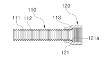
도시된 바와 같이, 본 발명의 일 실시 예에 따른 금속 주름관(100)은 주름관 본체(110) 및 조임너트(120)를 포함하여 구성될 수 있다. 또한, 본 발명의 일 실시 예에 따른 금속 주름관(100)은 조임볼트(130)를 더 포함하여 구성될 수 있다.As shown in the figure, the metal
주름관 본체(110)는 길이방향을 따라 산(111)과 골(112)이 반복되는 주름관의 형태로 이루어지며, 이러한 주름관 본체(110)의 길이방향 양단 중 적어도 한쪽에는 길이방향을 기준으로 바깥족에 위치한 하나 또는 둘 이상의 산이 외측 방향으로 펼쳐져 걸림턱(113)을 형성한다.The corrugated pipe
조임너트(120)는 주름관 본체(110)의 길이방향 일단이 삽입되는 상태로 주름관 본체(110)와의 분리 방지를 위해 주름관 본체(110)의 걸림턱(113)과 대응되는 내향 돌출턱(121)이 형성된 형태이다. 이에 따라, 조임너트(120)는 주름관 본체(100)의 길이방향 일단에만 걸림턱(113)이 형성되는 경우 하나의 조임너트(120)가 해당 주름관 본체(110)에 끼워질 것이며, 주름관 본체(110)의 길이방향 양단에 각각 걸림턱(113)이 형성되는 경우 두 개의 조임너트(120)가 해당 주름관 본체(110)의 길이방향 양쪽에 각각 끼워지게 된다.The tightening
참고로, 본 실시 예에서는 주름관 본체(110)의 길이방향 일단에만 걸림턱(113)이 형성되고, 이에 따라 하나의 조임너트(120)가 주름관 본체(110)에 분리 방지되는 상태로 끼워진 예를 설명하고 있지만, 상술한 기재에서 알 수 있는 바와 같이 본 발명이 이에 한정되는 것은 아니다.For example, in this embodiment, the latching
상술한 구성에 의해서, 주름관 본체(110) 및 조임너트(120) 간의 결합이 주름관 본체(110)의 걸림턱(113) 및 조임너트(120) 내면의 내향 돌출턱(121)을 통해 이루어짐에 따라, 금속 주름관(100)의 구조는 단순화되면서도 주름관 본체(110) 및 조임너트(120) 간 기밀한 연결한 가능하다. 그리고 이는 해당 금속 주름관(100)의 생산성 향상 및 제조 원가의 절감으로 이어지게 된다.Since the coupling between the bellows pipe
그리고 주름관 본체(110)의 산(111)과 골(112)이 반복되는 본체 부분으로부터 걸림턱(113)을 향하는 방향을 전방으로 정할 때, 걸림턱(113)은 전방으로 경사진 형태인 동시에 조임너트(120)의 내향 돌출턱(121)은 후방으로 경사진 경사면(121a)을 갖는 형태일 수 있다. 또한, 주름관 본체(110)의 걸림턱(113) 및 조임너트(120)의 내향 돌출턱(121)의 기울기는 30° 내지 60°의 범위 내에서 정해지는 것일 수 있다.When the direction in which the
이러한 구성에 의해서, 주름관 본체(110)의 외면과 조임너트(120)의 내면 간 갭(gap)을 줄이면서 걸림턱(113) 및 내향 돌출턱(121)을 주름관 본체(110) 및 조임너트(120)에 각각 형성시킬 수 있고, 이에 따라 걸림턱(113) 및 내향 돌출턱(121)을 통한 주름관 본체(110) 및 조임너트(120) 간 기밀 연결 부분에서 주름관 본체(110)와 조임너트(120) 간의 상호 유동 현상이 최소화될 수 있다.The
미설명된 부호 30은 조임너트(120)에 결합되는 조임볼트(130)를 예시한 것이며, 이러한 조임볼트(130)의 구체적인 구성 및 기능은 본 출원인의 등록특허인 특허 제10-1295220호 “가스용 금속 주름관 호스 제조방법 및 그 금속 주름관 호스”에 기재된 내용을 참조하면 될 것이므로, 본 실시 예에서 이에 대한 구체적인 설명은 생략한다.The reference numeral 30 designates a
다음은 도 2에 도 3 내지 도 6을 더 참조하여 본 발명의 일 실시 예에 따른 금속 주름관의 제조방법에 대해 설명한다.Next, a method of manufacturing a metal corrugated pipe according to an embodiment of the present invention will be described with reference to FIG. 2, FIG. 3 to FIG. 6, and FIG.
도 3은 본 발명의 일 실시 예에 따른 금속 주름관 제조방법에 따라 회전 방지된 주름관 본체에 지름 확장장치가 결합되기 전 상태를 예시한 사시도3 is a perspective view illustrating a state before the diameter expanding device is coupled to the corrugated pipe body that is prevented from rotation according to the method for manufacturing a metal corrugated pipe according to the embodiment of the present invention.
도시된 바와 같이, 내향 돌출턱(121)이 내면에 형성된 조임너트(120)를 길이방향을 따라 산(111)과 골(112)이 반복되는 주름관 본체(110)의 길이방향 양쪽 중 적어도 한쪽에 끼운다.As shown in the figure, the tightening
그리고 주름관 본체(110)의 조임너트(120)가 끼워지는 쪽의 단부에 확장된 지름의 걸림턱(113)을 형성하기 위한 지름 확장장치(200)가 주름관 본체(110)에 결합된다. 이러한 지름 확장장치(200)의 세부 구성에 대해 설명한다.A
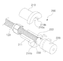
지름 확장장치(200)는 주름관 고정부(210,211) 및 회전 몸체부(220) 그리고 복수의 회전핀(230)을 포함하여 구성된다.The
주름관 고정부(210,211)는 주름관 본체(110)의 파지를 위해 서로 대칭되는 반원형 홈(210a,211a)이 길이방향을 따라 각각 형성되어 이러한 반원형 홈(210a,211a)들을 서로 연결하면서 주름관 본체(110)를 양쪽에서 파지하는 한 쌍으로 이루어진다. 이에 따라 주름관 고정부(210,211)들은 상호 간의 완전 분리가 가능한 형태로 결합되어 반원형 홈(210a,211a)들을 서로 연결하거나, 일측이 경첩 등을 통해 회전 가능하게 결합되어 상대 회전을 통해 반원형 홈(210a,211a)들을 서로 연결하는 형태일 수 있다.
이러한 주름관 고정부(210,211)들은 주름관 본체(110)의 회전을 방지하는 기능을 한다.The corrugated
또한, 주름관 고정부(210,211)들은 반원형 홈(210a,211a)의 길이방향 일단에 지름이 확장되는 방향으로 경사지게 연장되는 경사면(210b,211b)이 각각 형성된다.The corrugated
회전 몸체부(220)는 주름관 본체(110)의 일단에 삽입되는 삽입 안내 돌기(221) 및 이러한 삽입 안내 돌기(221)의 길이방향 일단으로부터 주름관 고정부(210,211)의 경사면(210b,211b)과 대응되는 기울기로 형성되는 경사면부(222)를 포함하여 구성된다.The
회전핀(230)은 삽입 안내 돌기(221)의 길이방향 일단으로부터 방사형으로 회전 몸체부(220)의 경사면부(222)에 형성된다.The
부연 설명하면, 본 실시 예에서는 주름관 고정부(210,211)가 주름관 본체(110)의 삽입 및 파지를 위해 반원형 홈(210a,211a)을 각각 형성한 한 쌍의 바이트 구성인 것을 예로 하였으나, 본 발명이 이에 한정되는 것은 아니다.In the present embodiment, the corrugated
상술한 지름 확장장치(200)의 구성에 의해서, 주름관 본체(110)가 길이방향 일단을 주름관 고정부(210,211)들의 경사면(210b,211b) 안쪽에 위치시키는 상태로 주름관 고정부(210,211)들을 통해 회전 방지된다.The
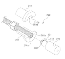
다음은 도 4 및 도 5를 참조하여 지름 확장장치(200)를 통해 주름관 본체(110)의 길이방향 일단이 지름 확장되어 걸림턱(113)을 형성하는 과정에 대해 설명한다.4 and 5, a description will be made of a process of forming the
도 4는 도 3에 따른 회전 방지된 주름관 본체에 지름 확장장치가 결합된 상태를 예시한 사시도이고, 도 5는 도 4에 따른 회전 방지된 주름관 본체에 지름 확장장치가 결합된 상태의 단면도FIG. 4 is a perspective view illustrating a state in which a diameter expanding device is coupled to the corrugated pipe main body according to FIG. 3, FIG. 5 is a cross-
도시된 바와 같이, 회전 몸체부(220)의 삽입 안내 돌기(221)가 주름관 본체(110)의 길이방향 일단에 삽입되어 경사면부(222)의 길이방향 일단이 주름관 본체(110)의 길이방향 일단에 접한다.The inserting
이러한 상태에서, 회전 몸체부(220)가 회전하면서 주름관 고정부(210,211)들 방향으로 점진적인 이동을 하여 주름관 본체(110)의 길이방향 일단이 주름관 고정부(210,211)들의 경사면(210b,211b)과 회전 몸체부(220)의 경사면부(222) 사이에서 외측 방향으로 벌려지면서 조임너트(120)의 내향 돌출턱(121)을 걸리게 하는 걸림턱(113)을 형성한다. 이때, 주름관 본체(110)의 길이방향 일단이 외측 방향으로 벌려지는 과정에서 회전핀(230)이 주름관 본체(110)의 벌려지는 내면과 경사면부(222) 사이에서 면 간의 마찰력을 감소시킨다. 즉, 회전핀(230)이 회전을 통해 주름관 본체(110)의 내면 및 회전 몸체부(220)의 경사면부(222) 간의 마찰을 감소시키는 기능에 의해서, 해당 주름관 본체(110)의 길이방향 일단이 외측으로 벌려지면서 걸림턱(113)을 형성하는 과정에서 해당 주름관 본체(110)의 벌려지는 영역이 찢어지는 등의 훼손으로부터 보호될 수 있다.In this state, the
또한, 이와 같이 주름관 본체(110)의 길이방향 일단에 걸림턱(113)을 형성시키는 단계에서, 주름관 고정부(110,111)의 경사면(210b,211b) 및 회전 몸체부(220)의 경사면부(222) 기울기가 각각 30° 내지 60°의 범위로 형성되고, 이에 따라 주름관 본체(110)의 걸림턱(113)이 해당 주름관 본체(110)의 외면으로부터 30° 내지 60°의 각도로 경사지면서 형성되는 과정이 포함될 수 있다.The inclined faces 210b and 211b of the corrugated
도 6은 도 4 내지 도 5의 상태에서 지름 확장장치(200)를 통해 주름관 본체(110)에 경사진 걸림턱(113)이 형성되어 조임너트(120)의 분리가 방지되는 상태를 예시한 단면도이다.6 is a cross-sectional view illustrating a state in which the engaging
도시된 바와 같이, 도 4 내지 도 5의 과정을 통해 주름관 본체(110)의 길이방향 일단에 걸림턱(113)이 형성된 후, 지름 확장장치(200)의 회전 몸체부(220) 및 회전핀(230)이 해당 주름관 본체(110)의 길이방향 일단으로부터 분리되는 동시에 해당 주름관 본체(110)는 지름 확장장치(200)의 주름관 고정부(210,211)로부터 분리되어 도 2에 예시된 것처럼 주름관 본체(110)에 조임너트(120)가 분리 방지되게 결합된 금속 주름관(100)을 형성한다. 4 and 5, the engaging
상술한 도 1 내지 도 6을 참조한 설명을 통하여 알 수 있는 바와 같이, 본 발명에 따른 금속 주름관 및 그 제조방법은, 금속 주름관의 주름관 본체 및 조임너트 간의 결합 구조가 단순화되면서도 기밀한 연결은 가능케 하여 해당 금속 주름관의 생산성 향상 및 제조원가의 절감을 가능케 한다.1 through 6, the metal corrugated pipe according to the present invention and its manufacturing method can simplify the connection structure between the corrugated pipe main body and the tightening nut of the metal corrugated pipe, It is possible to improve the productivity of the metal corrugated tube and to reduce the manufacturing cost.
다음은 도 7 및 도 8을 참조하여 본 발명의 일 실시 예에 따른 플레어 이음부를 갖는 금속 주름관에 대해 설명한다.Next, a metal corrugated pipe having a flared joint according to an embodiment of the present invention will be described with reference to FIGS. 7 and 8. FIG.
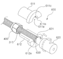
도 7은 본 발명의 일 실시 예에 따른 플레어 이음부를 갖는 금속 주름관의 사시도이고, 도 8은 본 발명의 일 실시 예에 따른 플레어 이음부를 갖는 금속 주름관의 단면도이다.FIG. 7 is a perspective view of a metal corrugated pipe having a flared joint according to an embodiment of the present invention, and FIG. 8 is a sectional view of a metal corrugated pipe having a flared joint according to an embodiment of the present invention.
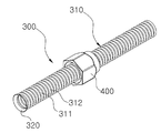
도시된 바와 같이, 본 실시 예에 따른 플레어 이음부를 갖는 금속 주름관(300 : 이하 “금속 주름관”이라 약칭함)은 주름관 본체(310) 및 플레어 이음부(320)를 포함하여 형성된다.As shown in the figure, a metal corrugated pipe 300 (hereinafter abbreviated as "metal corrugated pipe") having a flared joint according to the present embodiment is formed to include a corrugated pipe
주름관 본체(310)는 길이방향을 따라 산(311)과 골(312)이 반복되는 주름관의 형태로 이루어진다.The corrugated pipe
플레어 이음부(320)는 길이방향을 기준으로 주름관 본체(310)의 양쪽 중 적어도 한쪽에 주름관 본체(310)의 단부가 바깥쪽으로 벌려져 형성된다. 부연 설명하면, 플레어 이음부(320)는 길이방향을 기준으로 주름관 본체(310)의 단부에 위치하는 하나 또는 둘 이상의 산(311)이 골(312)과 함께 외측 방향으로 펼쳐져 형성된다.The flared joint 320 is formed on at least one of both sides of the bellows
그리고 주름관 본체(310)로부터 플레어 이음부(320)를 향하는 방향을 전방으로 정할 때, 플레어 이음부(320)의 전방 단부의 외경은 주름관 본체(310)의 외경을 기준으로 5∼25% 크게 형성되는 것일 수 있다. 또한, 플레어 이음부(320)는 주름관 본체(310)의 길이방향을 기준으로 주름관 본체(310)로부터 25°∼55°의 기울기로 형성되는 것일 수 있다. 도면을 참조하여 부연 설명하면, 도 2에 도시된 것처럼, 플레어 이음부(320)는 주름관 본체(310)의 외면을 길이방향을 따라 연결한 가상선을 기준으로 상기 가상선과 이루는 각도(θ)가 25°∼55°의 범위가 되도록 형성될 수 있다.The outer diameter of the front end of the flared joint 320 is 5 to 25% larger than the outer diameter of the bellows
또한, 플레어 이음부(320)는 안쪽 면이 연마를 통해 평평한 면의 상태일 수 있다.Also, the flare joint 320 may be in the form of a planar surface with its inner surface polished.
상술한 바와 같이 플레어 이음부(320)는 외경이 주름관 본체(310)의 외경에 비해 5∼25% 크게 형성되고, 주름관 본체(310)의 길이방향을 기준으로 주름관 본체(310)로부터 25°∼55°의 기울기로 형성됨에 따라, 해당 주름관 본체(310)에 끼워진 너트형 조인트 부재(400)는 주름관 본체(310)의 외경에 비해 현저히 큰 플레어 이음부(320)의 외경으로 인해 주름관 본체(310)로부터 분리되는 현상이 방지된다. 그리고 플레어 이음부(320)의 경사진 외면과 너트형 조인트 부재(400)의 내면 간에 충분한 면 접촉이 이루어지고, 플레어 이음부(320)의 경사진 내면과 볼트형 조인트 부재(500)의 외면 간에 충분한 면 접촉이 이루어지면서 기밀 기능이 크게 향상될 수 있고, 이를 위해 너트형 조인트 부재(400) 및 볼트형 조인트 부재(500)는 각각 플레어 이음부(320)의 기울기와 대응되는 경사면(410, 510)을 형성한 형태일 수 있다. 이때, 플레어 이음부(320)의 안쪽 면, 다시 말해 플레어 이음부(320)의 경사진 내면이 연마를 통한 평평한 면의 상태이므로, 볼트형 조인트 부재(500)의 경사면(510)과 보다 기밀하게 면 접촉되면서 기밀 기능이 극대화될 수 있다.As described above, the flare joint 320 is formed such that the outer diameter thereof is 5 to 25% larger than the outer diameter of the bellows
또한, 플레어 이음부(320)는 전방 단부가 안쪽으로 접히어 내면에 접하는 형태일 수 있다.In addition, the flare joint 320 may have a shape in which the front end portion is inwardly folded and contacts the inner surface.
상술한 구성에 의해서, 금속 주름관(300)의 길이방향 일단을 중심으로 너트형 조인트 부재(400) 및 볼트형 조인트 부재(500)의 기밀 유지형 결합이 별도의 결합용 부품을 필요로 하지 않으면서 이루어질 수 있고, 이에 따라 금속 주름관(300)을 포함하여 해당 결합 구조는 단순화되면서도 해당 결합 부위의 기밀 성능은 크게 향상될 수 있다. 그리고 이는 해당 금속 주름관(300)의 생산성 향상 및 제조 원가의 절감으로 이어지게 된다.Tight coupling of the nut type
다음은 도 9 내지 도 12를 참조하여 본 발명의 일 실시 예에 따른 플레어 이음부를 갖는 금속 주름관의 가공장치에 대해 설명한다.9 to 12, an apparatus for processing a metal corrugated pipe having a flared joint according to an embodiment of the present invention will be described.
도 9는 본 발명의 일 실시 예에 따른 플레어 이음부를 갖는 금속 주름관의 가공장치를 예시한 사시도이다.9 is a perspective view illustrating an apparatus for processing a metal corrugated pipe having a flared joint according to an embodiment of the present invention.
도시된 바와 같이, 본 발명의 일 실시 예에 따른 플레어 이음부를 갖는 금속 주름관의 가공장치(600 : 이하 “가공장치”라 약칭함)는 한 쌍의 주름관 고정부(611,612), 플레어 가공부(620) 및 복수의 회전핀(630)을 포함하여 구성된다.As shown in the figure, a processing apparatus 600 (hereinafter abbreviated as a "processing apparatus") having a flared joint according to an embodiment of the present invention includes a pair of corrugated
한 쌍의 주름관 고정부(611,612)는 주름관 본체(310)의 파지를 위한 서로 대칭되는 반원형 홈(611a,612a)이 길이방향을 따라 각각 형성되되, 이러한 반원형 홈(611a,612a)들의 길이방향 일단에는 지름을 확장하는 방향으로 경사지는 경사면(611b,612b)이 각각 형성된다. 여기서, 경사면(611b,612b)의 기울기는 각각 반원형 홈(611a,612a)의 길이방향을 기준으로 반원형 홈(611a,612a)으로부터 25°∼55°의 기울기로 형성될 수 있다. The pair of corrugated
그리고 한 쌍의 주름관 고정부(611,642)는 그 반원형 홈(611a,611b)들의 연결에 의해 형성되는 파지홀(613, 도 7 참조) 내측에 주름관 본체(310)를 파지하되, 파지홀(613)을 개폐할 수 있는 형태의 결합을 한다.7) formed by the connection of the
즉, 한 쌍의 주름관 고정부(611,612)는 상호 간의 완전 분리가 가능한 방식으로 탈착 가능하게 결합되어 반원형 홈(611a,612a)들을 서로 연결하거나, 일측이 경첩 등을 통해 회전 가능하게 결합되어 상대 회전을 통해 반원형 홈(611a,612a)들을 서로 연결하는 형태일 수 있다. 부연 설명하면, 한 쌍의 주름관 고정부(611,612)는 주름관 본체(310)를 파지하여 회전을 방지시키는 기능을 하며, 본 실시 예에서는 이러한 한 쌍의 주름관 고정부(611,612)가 주름관 본체(310)의 삽입 및 파지를 위해 반원형 홈(611a,612a)을 각각 형성한 한 쌍의 바이트 구성인 것을 예로 하였으나, 본 발명이 이에 한정되는 것은 아니다.That is, the pair of corrugated
또한, 주름관 고정부(611,612)들의 반원형 홈(611a,611b)이 연결되어 형성되는 파지홀(613) 중 반원형 홈(611a,611b)들의 경사면을 통해 형성되는 영역의 선단부 지름은 주름관 본체(310)의 외경을 기준으로 5∼25% 크게 형성되는 것일 수 있다. The tip diameter of the area formed through the inclined surfaces of the
또한, 한 쌍의 주름관 고정부(611,612)에는 주름관 본체(310)의 골(312)에 삽입되어 플레어 가공부(620)의 점진적 이동 시 주름관 본체(310)의 밀림을 방지하는 스토퍼 돌기(611c,612c)가 반원형 홈(611a,612a)의 내면에 각각 형성되는 것일 수 있다.The pair of corrugated
플레어 가공부(620)는 주름관 고정부(611,612)들의 경사면(611b,612b)과 대응되는 기울기의 경사면부(621)를 포함하며, 주름관 고정부(611,612)들의 파지홀(613, 도 7 참조)에 파지되는 주름관 본체(310)의 일단에 경사면부(621)의 선단을 삽입한 상태로 회전 및 경사면(611b,612b) 방향으로의 점진적 이동을 한다. 또한, 플레어 가공부(620)는 주름관 고정부(611,612)들의 파지홀(613)에 파지된 주름관 본체(310)의 내측으로 경사면부(621)의 선단을 안내하기 위해, 주름관 본체(310)의 내경보다 작은 외경으로 경사면부(621)의 선단으로부터 돌출 형성되는 삽입 안내 돌기(622)를 더 포함할 수 있다.The flared
복수의 회전핀(630)은 플레어 가공부(620)에 형성되는 경사면부(621)의 선단을 기준으로 경사면부(621)에 방사형으로 설치되되, 플레어 가공부(620)의 회전 방향과 동일한 방향으로 제자리 회전할 수 있는 상태로 경사면부(621)에 각각 결합된다.The plurality of rotation pins 630 are radially provided on the
상술한 가공장치(600)를 통해 주름관 본체(310)에 플레어 이음부(320)가 형성되는 과정을 도 10 내지 도 12를 참조하여 설명한다.The process of forming the flared joint 320 in the
도 10 내지 도 12는 도 9의 실시 예에 따른 플레어 이음부를 갖는 금속 주름관의 가공장치를 통해 금속 주름관에 플레어 이음부가 형성되는 과정을 순차적으로 예시한 도면이다.FIGS. 10 to 12 sequentially illustrate a process of forming a flared joint in a metal corrugated pipe through a metal corrugated pipe processing apparatus having a flared joint according to the embodiment of FIG.
먼저, 도 10은 한 쌍의 주름관 고정부(411,412)를 통해 주름관 본체(310)가 회전 방지되는 상태로 고정되는 과정 및 이렇게 고정되는 주름관 본체(310)의 길이방향 일단에 플레어 가공부(420)가 플레어 이음부(320)의 가공을 위해 접하게 되는 상태를 예시한 것이다. 여기서, 플레어 가공부(420)는 주름관 본체(310)에 삽입되는 삽입 안내 돌기(622)의 삽입 동작에 안내되면서 주름관 본체(310)의 길이방향 일단에 접하게 된다.10 shows a process of fixing the corrugated pipe
그리고 도 11은 도 10의 상태에서 플레어 가공부(620)가 회전과 함께 주름관 본체(310)의 방향으로 점진적인 이동을 하고, 이에 따라 주름관 본체(310)의 길이방향 일단이 플레어 가공부(620)의 경사면부(621)에 의해 점진적으로 밀리면서 플레어 형태로 형성되는 과정을 예시한 것이다. 이때, 회전핀(630)이 주름관 본체(310)의 플레어 형태로 벌려지는 내면 및 플레어 가공부(620)의 경사면부(621) 사이에서 면 간의 마찰력을 감소시킨다. 즉, 회전핀(620)이 회전을 통해 주름관 본체(310)의 플레어 형태로 벌려지는 내면 및 플레어 가공부(620)의 경사면부(621) 간 마찰을 감소시키며, 이러한 회전핀(630)의 기능에 의해서, 해당 주름관 본체(310)의 길이방향 일단이 플레어 형태로 벌려지면서 플레어 이음부(320)를 형성하는 과정에서 해당 주름관 본체(310)의 플레어 형태로 벌려지는 영역이 파열 등의 훼손으로부터 보호될 수 있다.11, in the state of FIG. 10, the
도 12는 도 11을 통한 플레어 가공부(620)의 회전 및 점진적인 이동 동작이 주름관 고정부(611,612)의 경사면(611b,612b)까지 진행되면서 주름관 본체(310)의 플레어 형태로 벌려지는 영역이 주름관 고정부(611,612)의 경사면(611b,612b)에 접하는 상태까지 진행되어 플레어 이음부(320)의 형성이 완료되고, 이에 따라 플레어 가공부(620)가 주름관 본체(310)로부터 분리되어 이동된 상태를 예시한 것이다. 이때, 플레어 이음부(320)의 안쪽 면은 플레어 이음부(320)를 형성하기 위한 플레어 가공부(620)의 가공 과정에서 연마되어 평평한 면의 상태가 된다.12 shows a state in which the flared
가공장치(600)는 도 9 내지 도 12를 참조하여 설명한 일련의 과정을 통해서 일반적인 금속 주름관을 도 7 및 도 8을 참조하여 설명한 플레어 이음부를 갖는 금속 주름관(300)으로 가공한다.The
상술한 도 7 내지 도 12를 참조한 설명을 통하여 알 수 있는 바와 같이, 본 발명에 따른 플레어 이음부를 갖는 금속 주름관 및 그 가공장치는, 금속 주름관의 연결을 위한 플레어 이음부가 해당 금속 주름관에 대한 직접 가공을 통해 형성되는 동시에 금속 주름관을 중심으로 그 벌어진 각도가 비교적 커 너트형 조인트 부재의 분리를 방지하는 기능 및 너트형 조인트 부재, 볼트형 조인트 부재와의 접촉 면적 확대에 따른 기밀 기능이 크게 향상될 수 있게 한다.7 to 12, the metal corrugated pipe having the flared joint according to the present invention and the machining apparatus thereof are characterized in that the flare joint for connecting the metal corrugated pipe is directly processed And at the same time, the opening angle is relatively large around the metal corrugated tube, the function of preventing the detachment of the nut-type joint member and the function of sealing the nut-type joint member and the confidential function due to the enlargement of the contact area with the bolt- Let's do it.
또한, 금속 주름관 간의 플레어 이음이 별도의 플레어 이음부를 필요로 하지 않으면서도 금속 주름관 간 연결 및 기밀 유지 기능은 우수한 형태로 제공될 수 있게 하여, 해당 금속 주름관의 제조원가 절감 및 현장에서의 작업성 향상이 이루어질 수 있게 한다.Further, since the flare joint between the metal corrugated pipes does not require a separate flare joint, the connection between the metal corrugated pipes and the airtightness maintenance function can be provided in a superior form, thereby reducing the manufacturing cost of the metal corrugated pipe and improving workability in the field. .
이상과 같이 본 설명에서는 구체적인 구성 요소 등과 같은 특정 사항들과 한정된 실시 예 및 도면에 의해 설명되었으나, 이는 본 발명의 보다 전반적인 이해를 돕기 위해서 제공된 것일 뿐, 본 발명은 상기의 실시 예에 한정되는 것은 아니며, 본 발명이 속하는 분야에서 통상적인 지식을 가진 자라면 이러한 기재로부터 다양한 수정 및 변형이 가능하다.While the present invention has been particularly shown and described with reference to exemplary embodiments thereof, it is to be understood that the invention is not limited to the exemplary embodiments or constructions. It will be understood by those skilled in the art that various changes in form and details may be made therein without departing from the spirit and scope of the invention as defined by the appended claims.
따라서 본 발명의 사상은 설명된 실시 예에 국한되어 정하여 저서는 안되며, 후술되는 청구범위뿐만 아니라 이 청구범위와 균등하거나 등가적인 변형이 있는 모든 것들은 본 발명 사상의 범주에 속한다고 할 것이다.Accordingly, the spirit of the present invention should not be construed as being limited to the embodiments described, and all the equivalents or equivalents of the claims, as well as the claims set forth below, fall within the scope of the present invention.
100 : 금속 주름관 110 : 주름관 본체
111 : 산 112 : 골
113 : 걸림턱 120 : 조임너트
121 : 내향 돌출턱 121a : 경사면
130 : 조임볼트 200 : 지름 확장장치
210,211 : 주름관 고정부 210a,211a : 반원형 홈
210b,211b : 경사면 213 : 원형 홈
220 : 회전 몸체부 221 : 삽입 안내 돌기
222 : 경사면부 230 : 회전핀
300 : 금속 주름관 310 : 주름관 본체
311 : 산 312 : 골
320 : 플레어 이음부 400 : 너트형 조인트 부재
410 : 경사면 500 : 볼트형 조인트 부재
510 : 경사면 600 : 가공장치
611,612 : 주름관 고정부 611a,612a : 반원형 홈
611b,612b : 경사면 611c,612c : 스토퍼 돌기
613 : 파지홀 620 : 플레어 가공부
621 : 경사면부 622 : 삽입 안내 돌기
630 : 회전핀100: metal corrugated pipe 110: corrugated pipe body
111: Mountain 112: Goals
113: Retaining jaw 120: Fastening nut
121: inward protruding
130: fastening bolt 200: diameter expansion device
210, 211:
210b, 211b: inclined surface 213: circular groove
220: rotating body part 221: insertion guide projection
222: slope portion 230: rotating pin
300: metal corrugated pipe 310: corrugated pipe body
311: Mt 312: Goals
320: flare joint part 400: nut type joint member
410: slope 500: bolt type joint member
510: slope 600: machining device
611, 612: Corrugated
611b, 612b:
613: Finger hole 620: Flare processing part
621: slant surface portion 622: insertion guide projection
630:
Claims (12)
상기 주름관 본체의 상기 걸림턱을 형성한 일단이 삽입되는 상태로 상기 주름관 본체와의 분리 방지를 위해 상기 걸림턱과 대응되는 내향 돌출턱이 형성된 적어도 하나의 조임너트를 포함하는 금속 주름관.A corrugated pipe main body having at least one of both ends in the longitudinal direction, one or two or more of the mountains positioned outwardly with respect to the longitudinal direction being unfolded outwardly to form a latching jaw;
And at least one fastening nut having an inwardly projecting protrusion corresponding to the fastening protrusion for preventing separation of the bellows pipe from the bellows pipe main body in a state in which the one end of the bellows pipe body having the fastening protrusion is inserted.
상기 주름관 본체의 상기 산과 골이 반복되는 본체 부분으로부터 상기 걸림턱을 향하는 방향을 전방으로 정할 때,
상기 걸림턱은 전방으로 경사진 형태인 동시에 상기 조임너트의 내향 돌출턱은 후방으로 경사진 경사면을 갖는 형태인 것을 특징으로 하는 금속 주름관.The method according to claim 1,
When the direction from the main body portion, in which the mountain and the valley of the corrugated pipe body are repeated, toward the engaging jaw is set forward,
Wherein the engaging jaw is inclined forward and the inward protruding jaw of the tightening nut has an inclined surface inclined rearward.
상기 걸림턱 및 내향 돌출턱의 기울기는 30° 내지 60°인 것을 특징으로 하는 금속 주름관.3. The method of claim 2,
Wherein the inclination of the engaging jaw and the inwardly projecting jaw is 30 to 60 degrees.
상기 주름관 본체의 상기 조임너트가 끼워지는 쪽의 단부에 확장된 지름의 걸림턱을 형성하기 위한 지름 확장장치가 상기 주름관 본체에 결합되되, 상기 지름 확장장치는, 상기 주름관 본체의 파지를 위해 서로 대칭되는 반원형 홈이 길이방향을 따라 각각 형성되어 상기 반원형 홈들을 연결하면서 상기 주름관 본체를 양쪽에서 파지하여 상기 주름관 본체의 회전을 방지하되 상기 반원형 홈들의 길이방향 일단에는 각각 지름이 확장되는 방향으로 경사지게 연장되는 경사면이 형성된 한 쌍의 주름관 고정부와, 상기 주름관 본체의 일단에 삽입되는 삽입 안내 돌기 및 상기 삽입 안내 돌기의 길이방향 일단으로부터 상기 주름관 고정부의 경사면과 대응되는 기울기로 형성되는 경사면부를 포함하는 회전 몸체부와, 상기 삽입 안내 돌기의 길이방향 일단으로부터 방사형으로 상기 경사면부에 형성되는 복수의 회전핀을 포함하여, 상기 주름관 본체가 길이방향 일단을 상기 주름관 고정부들의 경사면 안쪽에 위치시키는 상태로 상기 주름관 고정부들을 통해 회전 방지되는 단계;
상기 회전 몸체부의 상기 삽입 안내 돌기가 상기 주름관 본체의 길이방향 일단에 삽입되어 상기 경사면부의 길이방향 일단이 상기 주름관 본체의 길이방향 일단에 접하는 단계;
상기 회전 몸체부가 회전하면서 상기 주름관 고정부들 방향으로 점진적인 이동을 하여 상기 주름관 본체의 길이방향 일단이 상기 경사면과 상기 회전 몸체부의 경사면부 사이에서 외측 방향으로 벌려지면서 상기 조임너트의 내향 돌출턱을 걸리게 하는 상기 걸림턱이 형성되되, 상기 주름관 본체의 길이방향 일단이 외측 방향으로 벌려지는 과정에서 상기 회전핀이 상기 주름관 본체의 벌려지는 내면과 상기 경사면부의 사이에서 면 간의 마찰력을 감소시키는 단계를 포함하는 금속 주름관의 제조방법.Fitting a tightening nut formed on the inner surface of the inner protruding jaw to at least one of the longitudinal direction of the bellows main body in which the mountain and the bone are repeated along the longitudinal direction;
Wherein the diameter expanding device is coupled to the bellows main body in order to form a bell jaw of an enlarged diameter at an end of the bellows main body on the side where the bellows nut is inserted, Circular grooves are formed along the longitudinal direction to connect the semicircular grooves so as to grasp the corrugated pipe main body from both sides to prevent rotation of the corrugated pipe main body, and at one end in the longitudinal direction of the semicircular grooves, And a slope portion formed at a slope corresponding to the slope of the corrugated pipe fixing portion from one end in the longitudinal direction of the insertion guiding protrusion, A rotary body portion, From the step to the state, including a plurality of rotation pins formed on the inclined surface portion in a radial direction, of which the corrugated pipe body and the longitudinal end of the corrugated pipe is located at the inner inclined surface of the government to be non-rotating fixed parts through the corrugated pipe;
Wherein the inserting guide protrusion of the rotating body is inserted into one end of the corrugated pipe body in the longitudinal direction so that one longitudinal end of the inclined face portion contacts one longitudinal end of the corrugated pipe main body;
The rotatable body rotates gradually in the direction of the corrugated tube fixing parts so that one end in the longitudinal direction of the corrugated tube body is opened outwardly between the inclined surface and the inclined surface part of the rotating body part to catch the inward protruding jaws of the tightening nut And reducing the frictional force between the inner surface of the bellows main body and the inclined surface portion in the process of expanding one end in the longitudinal direction of the bellows main body in the outward direction of the bellows main body A method for manufacturing a metal corrugated pipe.
상기 회전 몸체부가 회전하면서 상기 주름관 고정부들 방향으로 점진적인 이동을 하여 상기 주름관 본체의 길이방향 일단이 상기 경사면과 상기 회전 몸체부의 경사면부 사이에서 외측 방향으로 벌려지면서 상기 조임너트의 내향 돌출턱을 걸리게 하는 상기 걸림턱이 형성되되, 상기 주름관 본체의 길이방향 일단이 외측 방향으로 벌려지는 과정에서 상기 회전핀이 상기 주름관 본체의 벌려지는 내면과 상기 경사면부의 사이에서 면 간의 마찰력을 감소시키는 단계에는,
상기 주름관 고정부의 경사면 및 상기 회전 몸체부의 경사면부 기울기가 각각 30° 내지 60°의 범위로 형성되어 상기 걸림턱이 상기 주름관 본체의 외면으로부터 30° 내지 60° 각도로 경사지면서 형성되는 과정이 포함되는 것을 특징으로 하는 금속 주름관의 제조방법.5. The method of claim 4,
The rotatable body rotates gradually in the direction of the corrugated tube fixing parts so that one end in the longitudinal direction of the corrugated tube body is opened outwardly between the inclined surface and the inclined surface part of the rotating body part to catch the inward protruding jaws of the tightening nut And reducing the frictional force between the inner surface of the bellows main body and the inclined surface portion in the process of expanding one end in the longitudinal direction of the bellows main body,
The slope of the corrugated pipe fixing part and the slope of the slope part of the rotating body part are each formed in a range of 30 to 60 degrees so that the engaging step is inclined at an angle of 30 to 60 from the outer surface of the corrugated pipe body Wherein the metal corrugated pipe is made of a metal.
길이방향을 기준으로 상기 주름관 본체의 양쪽 중 적어도 한쪽에 상기 주름관 본체의 단부가 바깥쪽으로 벌려져 형성되는 플레어 이음부를 포함하며,
상기 주름관 본체로부터 상기 플레어 이음부를 향하는 방향을 전방으로 정할 때, 상기 플레어 이음부의 전방 단부의 외경은 상기 주름관 본체의 외경을 기준으로 5∼25% 크게 형성되는 플레어 이음부를 갖는 금속 주름관.A corrugated pipe body in which mountains and valleys are repeated along the longitudinal direction; And
And a flared joint formed on at least one of both sides of the bellows main body with the end portion of the bellows main body opened outward with respect to the longitudinal direction,
And the outer diameter of the front end of the flared joint is formed to be 5 to 25% larger than the outer diameter of the bell tube main body when the direction from the bell tube main body to the flared joint is determined forward.
상기 플레어 이음부는 상기 주름관 본체의 길이방향을 기준으로 상기 주름관 본체로부터 25°∼55°의 기울기로 형성되는 것을 특징으로 하는 플레어 이음부를 갖는 금속 주름관.The method according to claim 6,
Wherein the flare joint portion is formed at an inclination of 25 ° to 55 ° with respect to the longitudinal direction of the corrugated pipe main body from the corrugated pipe main body.
상기 플레어 이음부는 전방 단부가 안쪽으로 접히어 내면에 접하는 형태인 것을 특징으로 하는 플레어 이음부를 갖는 금속 주름관.The method according to claim 6,
Wherein the flared joint has a shape in which a front end portion thereof is inwardly folded in contact with an inner surface thereof.
상기 플레어 이음부는 안쪽 면이 연마를 통해 평평한 면의 상태인 것을 특징으로 하는 플레어 이음부를 갖는 금속 주름관.The method according to claim 6,
Wherein the flared joint has a flat surface through an inner surface thereof.
상기 주름관 고정부들의 상기 경사면과 대응되는 기울기의 경사면부를 포함하며, 상기 파지홀에 파지된 주름관 본체의 일단에 상기 경사면부의 선단을 삽입한 상태로 회전 및 상기 경사면 방향으로의 점진적 이동을 하는 플레어 가공부;
상기 경사면부의 선단을 기준으로 상기 경사면부에 방사형으로 설치되되, 상기 플레어 가공부의 회전 방향과 동일한 방향으로 제자리 회전할 수 있는 상태로 상기 경사면부에 각각 결합되는 복수의 회전핀을 포함하는 플레어 이음부를 갖는 금속 주름관의 가공장치.Circular grooves symmetrical to each other for gripping the corrugated pipe main body are formed along the longitudinal direction, and one end of the semicircular grooves in the longitudinal direction is formed with inclined surfaces inclining in the direction of expanding the diameter, A pair of corrugated pipe fixing parts for gripping the corrugated pipe main body inside the phage hole and making the coupling in such a manner as to open and close the phihi hole;
And a tapered surface portion corresponding to the tapered surface of the corrugated tube fixing portions, wherein a flare process is performed in which the tip of the tapered surface portion is inserted into one end of the corrugated pipe body gripped by the tapered hole and rotated and progressively moved in the inclined surface direction part;
And a plurality of rotation pins which are radially provided on the inclined surface portion with respect to the tip of the inclined surface portion and are respectively coupled to the inclined surface portion in a state of being able to rotate in the same direction as the rotation direction of the flared portion, A processing device for a metal corrugated pipe having
상기 플레어 가공부는, 상기 파지홀에 파지된 주름관 본체의 내측으로 상기 경사면부의 선단을 안내하기 위해 상기 주름관 본체의 내경보다 작은 외경으로 상기 경사면부의 선단으로부터 돌출 형성되는 삽입 안내 돌기를 더 포함하는 것을 특징으로 하는 플레어 이음부를 갖는 금속 주름관의 가공장치.11. The method of claim 10,
The flare processing unit may further include an insertion guide protrusion protruding from an end of the inclined face portion to an inner diameter of the corrugated pipe body gripped by the grip hole and having an outer diameter smaller than an inner diameter of the corrugated pipe body to guide the tip of the inclined face portion And the flare joint portion is made of a metal material.
상기 한 쌍의 주름관 고정부는, 상기 주름관 본체의 골에 삽입되어 상기 플레어 가공부의 점진적 이동 시 상기 주름관 본체의 밀림을 방지하는 스토퍼 돌기가 상기 반원형 홈의 내면에 각각 형성되는 것을 특징으로 하는 플레어 이음부를 갖는 금속 주름관의 가공장치.11. The method of claim 10,
Wherein the pair of corrugated pipe fixing parts are formed on the inner surface of the semicircular groove, respectively, with stopper protrusions inserted into the corrugation of the corrugated pipe main body to prevent the bending of the corrugated pipe body when the flared part is gradually moved. A processing device for a metal corrugated pipe having
Priority Applications (1)
| Application Number | Priority Date | Filing Date | Title |
|---|---|---|---|
| PCT/KR2018/002298 WO2018155971A1 (en) | 2017-02-24 | 2018-02-26 | Metal corrugated pipe having flare joint part, and processing apparatus and production method therefor |
Applications Claiming Priority (2)
| Application Number | Priority Date | Filing Date | Title |
|---|---|---|---|
| KR1020170024748 | 2017-02-24 | ||
| KR20170024748 | 2017-02-24 |
Publications (1)
| Publication Number | Publication Date |
|---|---|
| KR20180098113A true KR20180098113A (en) | 2018-09-03 |
Family
ID=63601057
Family Applications (1)
| Application Number | Title | Priority Date | Filing Date |
|---|---|---|---|
| KR1020170135582A Ceased KR20180098113A (en) | 2017-02-24 | 2017-10-19 | Metallic bellows with flare joint and processing apparatus and manufacturing method thereof |
Country Status (1)
| Country | Link |
|---|---|
| KR (1) | KR20180098113A (en) |
Cited By (2)
| Publication number | Priority date | Publication date | Assignee | Title |
|---|---|---|---|---|
| CN111097826A (en) * | 2020-01-16 | 2020-05-05 | 湖北满天星节能环保科技有限公司 | Modular furnace supporting bellows end forming tool and using method |
| CN118650392A (en) * | 2024-08-21 | 2024-09-17 | 贵州航飞精密制造有限公司 | A processing method for expanding bolts for narrow spaces |
Citations (2)
| Publication number | Priority date | Publication date | Assignee | Title |
|---|---|---|---|---|
| KR20100028519A (en) | 2009-12-09 | 2010-03-12 | 주식회사 마스테코 | Sealing device of connecting part of metal bellows pipe |
| KR101295220B1 (en) | 2011-10-26 | 2013-08-12 | 신화옥 | Connecting method and connecting member using flexible metallic gas tube |
-
2017
- 2017-10-19 KR KR1020170135582A patent/KR20180098113A/en not_active Ceased
Patent Citations (2)
| Publication number | Priority date | Publication date | Assignee | Title |
|---|---|---|---|---|
| KR20100028519A (en) | 2009-12-09 | 2010-03-12 | 주식회사 마스테코 | Sealing device of connecting part of metal bellows pipe |
| KR101295220B1 (en) | 2011-10-26 | 2013-08-12 | 신화옥 | Connecting method and connecting member using flexible metallic gas tube |
Cited By (2)
| Publication number | Priority date | Publication date | Assignee | Title |
|---|---|---|---|---|
| CN111097826A (en) * | 2020-01-16 | 2020-05-05 | 湖北满天星节能环保科技有限公司 | Modular furnace supporting bellows end forming tool and using method |
| CN118650392A (en) * | 2024-08-21 | 2024-09-17 | 贵州航飞精密制造有限公司 | A processing method for expanding bolts for narrow spaces |
Similar Documents
| Publication | Publication Date | Title |
|---|---|---|
| CN109642688B (en) | Hybrid push-to-connect mating devices and assemblies | |
| CN108027094B (en) | Locking Pipe Fitting Assembly, Apparatus and Method | |
| CN109073117B (en) | Mix push-in type connection adapting device, arrangement and method | |
| US5080405A (en) | Corrugated pipe coupling | |
| KR101828783B1 (en) | Nonwelded pipe connecting joint using attachable type flange | |
| US4070046A (en) | Pipe and tubing connecting sleeve | |
| US20060125235A1 (en) | Fluid coupling with dual function retention ring | |
| JPH07269749A (en) | Pipe joint device | |
| WO2002057673A2 (en) | Mechanical pipe coupling derived from a standard fitting | |
| JP6289122B2 (en) | Detachment prevention fitting | |
| WO2011151949A1 (en) | Fire hose coupler | |
| JP7045684B2 (en) | Pipe fittings | |
| KR20120083266A (en) | Push-fit pipe fitting system with support sleeve | |
| KR20180098113A (en) | Metallic bellows with flare joint and processing apparatus and manufacturing method thereof | |
| CN110114607A (en) | Press-in cooperation device, component and method | |
| US11035504B2 (en) | Connection structure of metal corrugated pipe | |
| JP5111212B2 (en) | Water pipe connector | |
| KR101292919B1 (en) | Coupling structure | |
| JP5576691B2 (en) | Pipe fitting | |
| JP2019120309A (en) | Metal tube joint | |
| CN108240516A (en) | A kind of limiting auto-locking suspension metal tube fast connecting joint | |
| JP7017441B2 (en) | Pipe fittings | |
| JP2009144755A (en) | Pipe joint with anti-rotation function | |
| JP4781164B2 (en) | Connection method of joint body | |
| JP5525897B2 (en) | Pipe fitting |
Legal Events
| Date | Code | Title | Description |
|---|---|---|---|
| A201 | Request for examination | ||
| PA0109 | Patent application |
Patent event code: PA01091R01D Comment text: Patent Application Patent event date: 20171019 |
|
| PA0201 | Request for examination | ||
| PG1501 | Laying open of application | ||
| E902 | Notification of reason for refusal | ||
| PE0902 | Notice of grounds for rejection |
Comment text: Notification of reason for refusal Patent event date: 20181101 Patent event code: PE09021S01D |
|
| E601 | Decision to refuse application | ||
| PE0601 | Decision on rejection of patent |
Patent event date: 20190107 Comment text: Decision to Refuse Application Patent event code: PE06012S01D Patent event date: 20181101 Comment text: Notification of reason for refusal Patent event code: PE06011S01I |