KR20180088882A - Digital compensator - Google Patents
Digital compensator Download PDFInfo
- Publication number
- KR20180088882A KR20180088882A KR1020187018592A KR20187018592A KR20180088882A KR 20180088882 A KR20180088882 A KR 20180088882A KR 1020187018592 A KR1020187018592 A KR 1020187018592A KR 20187018592 A KR20187018592 A KR 20187018592A KR 20180088882 A KR20180088882 A KR 20180088882A
- Authority
- KR
- South Korea
- Prior art keywords
- signal
- basic
- chain
- coefficients
- linear
- Prior art date
Links
Images


Classifications
-
- H—ELECTRICITY
- H03—ELECTRONIC CIRCUITRY
- H03F—AMPLIFIERS
- H03F1/00—Details of amplifiers with only discharge tubes, only semiconductor devices or only unspecified devices as amplifying elements
- H03F1/32—Modifications of amplifiers to reduce non-linear distortion
- H03F1/3241—Modifications of amplifiers to reduce non-linear distortion using predistortion circuits
- H03F1/3252—Modifications of amplifiers to reduce non-linear distortion using predistortion circuits using multiple parallel paths between input and output
-
- H—ELECTRICITY
- H03—ELECTRONIC CIRCUITRY
- H03F—AMPLIFIERS
- H03F1/00—Details of amplifiers with only discharge tubes, only semiconductor devices or only unspecified devices as amplifying elements
- H03F1/32—Modifications of amplifiers to reduce non-linear distortion
- H03F1/3241—Modifications of amplifiers to reduce non-linear distortion using predistortion circuits
- H03F1/3258—Modifications of amplifiers to reduce non-linear distortion using predistortion circuits based on polynomial terms
-
- H—ELECTRICITY
- H04—ELECTRIC COMMUNICATION TECHNIQUE
- H04B—TRANSMISSION
- H04B1/00—Details of transmission systems, not covered by a single one of groups H04B3/00 - H04B13/00; Details of transmission systems not characterised by the medium used for transmission
- H04B1/02—Transmitters
- H04B1/04—Circuits
- H04B1/0475—Circuits with means for limiting noise, interference or distortion
-
- H—ELECTRICITY
- H04—ELECTRIC COMMUNICATION TECHNIQUE
- H04L—TRANSMISSION OF DIGITAL INFORMATION, e.g. TELEGRAPHIC COMMUNICATION
- H04L41/00—Arrangements for maintenance, administration or management of data switching networks, e.g. of packet switching networks
- H04L41/06—Management of faults, events, alarms or notifications
- H04L41/0654—Management of faults, events, alarms or notifications using network fault recovery
-
- H—ELECTRICITY
- H04—ELECTRIC COMMUNICATION TECHNIQUE
- H04B—TRANSMISSION
- H04B1/00—Details of transmission systems, not covered by a single one of groups H04B3/00 - H04B13/00; Details of transmission systems not characterised by the medium used for transmission
- H04B1/02—Transmitters
- H04B1/04—Circuits
- H04B2001/0408—Circuits with power amplifiers
- H04B2001/0425—Circuits with power amplifiers with linearisation using predistortion
Landscapes
- Engineering & Computer Science (AREA)
- Physics & Mathematics (AREA)
- Nonlinear Science (AREA)
- Power Engineering (AREA)
- Computer Networks & Wireless Communication (AREA)
- Signal Processing (AREA)
- General Physics & Mathematics (AREA)
- Mathematical Analysis (AREA)
- Mathematical Optimization (AREA)
- Pure & Applied Mathematics (AREA)
- Algebra (AREA)
- Amplifiers (AREA)
- Transmitters (AREA)
Abstract
디지털 보상에 대한 접근법은 비-선형 회로(예를 들어, 디지털-아날로그 변환기(DAC), 저역통과 필터, 변조기, 대역통과 필터, 및 전력 증폭기를 포함하는 비-선형 전송 체인)의 비교적 정확한 전치-역변환으로서 동작하는 디지털 전치-왜곡기(pre-distorter, DPD)에 대한 특정 구조를 사용하면서, 지속적인 업데이팅을 요구하지 않고 정확한 선형화를 제공하는 비-선형성 및/또는 파라미터들을 특성화하는 비교적 적은 수의 파라미터들을 사용한다.Approaches to digital compensation are relatively accurate transposition of non-linear circuits (e.g., non-linear transmission chains including digital-to-analog converters (DACs), lowpass filters, modulators, bandpass filters, Linearity that provides precise linearization without requiring continuous updating and / or a relatively small number of parameters that characterize parameters using a particular structure for a digital pre-distorter (DPD) Parameters.
Description
관련 출원들에 대한 상호 참조Cross reference to related applications
본 출원은 그 전체 내용이 본원에 참고로 포함된, 2015년 11월 30일자로 출원된 미국 특허 출원 제14/953,762호의 출원일의 우선권을 주장한다.This application claims the benefit of the filing date of U.S. Patent Application No. 14 / 953,762, filed November 30, 2015, the entire contents of which are incorporated herein by reference.
본 발명은 비-선형 회로의 디지털 보상에 관한 것으로, 특히, 비-선형 전력 증폭기 및 송신기 체인의 선형화에 관한 것이다. The present invention relates to digital compensation of non-linear circuits, and more particularly to linearization of non-linear power amplifiers and transmitter chains.
회로를 통과하는 원 신호의 품질을 복원하기 위해 디지털 보상을 적용하는 개념은 일상적인 것(routine)이다. 무선 기지국 또는 핸드셋의 무선 장치 내의 전력 증폭기는 인접 채널로의 스펙트럼 누출을 최소화하기 위해 기저대역에서 디지털적으로 보상된다. 스피커의 오디오 증폭기는 높은 충실도(fidelity)를 달성하기 위해 디지털적으로 보상된다. 많은 그러한 예들에서, 볼테라 시리즈들(Volterra series)의 변동들이 비선형성의 동적 특성을 설명하기 위해 채택되었다. 위너(Wiener), 위너-해머스타인(Wiener-Hammerstein), 일반적 메모리리스 다항식(General Memoryless Polynomial)은, 비-선형 회로를 통과하기 전에 입력 신호를 수정하는 데 사용되는, 디지털 전치 왜곡기(pre-distorter)에 널리 사용되는 구조들이다. 일반적으로, 이러한 구조들은, 공정, 온도, 공급 전압, 및 기타 동작 조건들 포함하는, 특정 장치(테스트 중인 디바이스, DUT)의 변동들에 대한 보상기 파라미터들의 민감도로 인한 견고성 문제들(robustness issues) 뿐만 아니라, 다항식 차수가 3 내지 5를 초과하는 경우 지수적 복잡성을 가진다. The concept of applying digital compensation to restore the quality of the original signal through the circuit is a routine. A power amplifier in the wireless base station or wireless device of the handset is digitally compensated at the baseband to minimize spectral leakage to adjacent channels. The audio amplifier of the speaker is digitally compensated to achieve high fidelity. In many such instances, variations in the Volterra series have been adopted to account for dynamic properties of nonlinearity. Wiener, Wiener-Hammerstein, and General Memoryless Polynomial use a digital predistorter (pre), which is used to modify the input signal before passing through the non-linear circuit, -distorter). In general, these structures are not only robustness issues due to the sensitivity of compensator parameters to variations in a particular device (device under test, DUT), including process, temperature, supply voltage, and other operating conditions But has exponential complexity when the polynomial degree exceeds 3 to 5.
도 1을 참조하면, 무선 전력 증폭기의 선형화의 예에서, 기저대역 또는 중간 주파수에서 디지털 입력 신호 ![]()
![]()
![]()
![]()
![]()
![]()
![]()
![]()
![]()
![]()
![]()
![]()
![]()
![]()
![]()
![]()
일부 예들에서, 비-선형 함수는 볼테라 항들의 감소된 세트, 예를 들어 지연 다항식이다:In some examples, the non-linear function is a reduced set of Volterra terms, e.g., a delay polynomial:

송신 체인의 비-선형 효과를 반전시키기 위해, 일반적으로, 그러한 시리즈들 표현의 비교적 많은 수의 항들 필요하고, 이들 항들(예를 들어, ![]()
![]()
![]()
![]()
![]()
![]()
일반적인 양상에서, 디지털 보상에 대한 접근법은, 비선형성을 특징으로 하는 비교적 작은 수의 파라미터들 및/또는 지속적인 업데이팅의 필요 없이 정확한 선형성을 제공하는 파라미터들을 사용하면서, 비-선형 회로(예를 들어, 디지털-아날로그 변환기(DAC), 저역통과 필터, 변조기, 대역통과 필터 및 전력 증폭기를 포함하는 비-선형 송신 체인)의 상대적으로 정확한 전치-역변환으로서 작용하는 디지털 전치-왜곡기(DPD)의 특정 구조를 사용한다.In a general aspect, the approach to digital compensation may be based on a nonlinear circuit (e.g., a nonlinear circuit) using a relatively small number of parameters featuring nonlinearity and / or parameters that provide accurate linearity without the need for continuous updating. (DPD) that acts as a relatively precise transposition-inverse transform of a non-linear transmission chain (e.g., a non-linear transmission chain including a digital-to-analog converter (DAC), a lowpass filter, a modulator, a bandpass filter, and a power amplifier) Structure.
일반적으로, 이러한 접근법은 변조된 신호의 변조 및 후속(예를 들어, 비선형) 증폭들로부터 발생하는 비-선형성의 근본적인 소스들과 더욱 밀접하게 관련된다. 특히, 이 접근법은 많은 수의 파라미터들이 필요하지 않고 고조파(harmonic) 및 상호 변조 왜곡 효과들을 보다 직접적으로 포착한다.In general, this approach is more closely related to the modulation of the modulated signal and the underlying sources of non-linearity resulting from subsequent (e.g., non-linear) amplifications. In particular, this approach does not require a large number of parameters and more directly captures harmonic and intermodulation distortion effects.
일 양상에서, 일반적으로, 전치-왜곡기는 입력 ![]()
![]()
![]()
![]()
![]()
![]()
여기서, ![]()
![]()
![]()
![]()
![]()
![]()
![]()
![]()
일부 예들에서, 기본 함수들의 세트는 "밸런싱된 다항식" 형태를 사용하여 조합되고, 이는 다음과 같이 표현될 수 있다:In some instances, a set of basic functions is combined using a " balancing polynomial " form, which can be expressed as:

여기서, 
일부 경우들에서, 지수들 
![]()
![]()
![]()
![]()
일부 예들에서, 디바이스에 대한 파라미터들은 동작, 예를 들어, 제작(fabrication), 제조(manufacture), 배치(deployment), 및/또는 주기적인 유지 보수 시간, 그 다음 후속 동작에 대한 세트, 전에 결정된다. 일부 예들에서, 파라미터들의 상이한 세트들은 상이한 동작 조건들(예를 들어, 동작 온도, 공급 전압 등)에 대해 결정되고, 동작 조건의 감지에 따라 동작시 파라미터들의 상이한 세트들이 사용된다. 일부 예들에서, 온도, 공급 전압, 출력 전력, 변조 모드, 부품 수명, 샘플링 속도 및 부품 시그니처(signature)과 같은 외부 파라미터들은 이전에 구성된 예측기 유닛에 대한 입력이다. 이들에 기초하여, 유닛은 동작 체제(regime)를 결정하고 보상기에 대한 업데이트된 계수들을 출력한다. 일부 예들에서, 부품 시그니처는 짧은 제조-시간 특성화(예를 들어, 소수의 톤 또는 특수한 송신 시퀀스)에 의해 획득된다.In some instances, the parameters for the device are determined prior to the operation, e.g., fabrication, manufacture, deployment, and / or periodic maintenance time, set for subsequent subsequent operations . In some instances, different sets of parameters are determined for different operating conditions (e.g., operating temperature, supply voltage, etc.), and different sets of parameters are used in operation according to sensing of operating conditions. In some instances, external parameters such as temperature, supply voltage, output power, modulation mode, component life, sampling rate, and component signature are inputs to a previously configured predictor unit. Based on these, the unit determines the operating regime and outputs updated coefficients for the compensator. In some instances, the part signature is obtained by a short manufacture-time characterization (e. G., A small number of tones or a special transmission sequence).
전술한 적어도 하나의 접근법은 감소된 동작-시간 계산 복잡도를 포함하는 이점을 가지며, 이에 의해 비교적 정확한 선형화(예를 들어, 비교 가능한 계산 자원들을 사용하는 다른 접근법과 관련하여)를 제공하면서, 전력 요구 사항들 및 다른 계산-관련 자원들의 사용을 감소시킨다. 회로의 비-선형 구조와 매칭하는 전치-왜곡기의 구조를 사용함으로써, 시스템을 정확하게 선형화하는데 필요한 계수들의 수는 감소되고, 이들 파라미터들은 시스템의 변동에 보다 견고하기 때문에, 출력 신호들(예: p(t))의 관찰을 기반으로 파라미터들을 지속적으로 업데이트할 필요가 없다. 예측기는, 예를 들어, 온도 변화들, 또는 공급 전압 변화들에 응답하여 계수들을 연속적으로 업데이트할 수 있다.The at least one approach described above has the advantage of including reduced operation-time computational complexity, thereby providing relatively accurate linearization (e.g., in connection with other approaches using comparable computational resources) And the use of other computation-related resources. By using the structure of the predistorter matching the non-linear structure of the circuit, the number of coefficients needed to precisely linearize the system is reduced, and because these parameters are more robust to system variations, the output signals (e.g., lt; RTI ID = 0.0 > p (t)) < / RTI > The predictor may continuously update coefficients in response to, for example, temperature changes, or changes in supply voltage.
본 발명의 다른 특징들 및 이점들은 하기의 설명, 및 청구항들로부터 명백해진다.Other features and advantages of the invention will be apparent from the following description, and from the claims.
도 1은 종래의 디지털 전치-왜곡 접근법의 블록도이다.
도 2는 본 접근법의 복수의 실시 예들을 나타내는 블록도이다.
도 3은 계수 보간 접근법을 나타내는 블록도이다.
도 4는 동작-시간 파라미터 추정 접근법을 도시하는 블록도이다.
도 5는 사전-동작 계수 모델링 접근법을 도시하는 블록도이다.
도 6은 조합된 계수 보간 및 동작 시간 파라미터 추정 접근법을 도시하는 블록도이다.
도 7은 예시적인 기본 형성 및 다항식 조합 실시 예의 블록도이다.
도 8은 정규화를 통합하는 대안적인 기본 형성 접근법의 블록도이다.Figure 1 is a block diagram of a conventional digital pre-distortion approach.
Figure 2 is a block diagram illustrating multiple embodiments of the present approach.
3 is a block diagram illustrating a coefficient interpolation approach.
4 is a block diagram illustrating an operation-time parameter estimation approach.
5 is a block diagram illustrating a pre-action coefficient modeling approach.
6 is a block diagram illustrating a combined coefficient interpolation and operating time parameter estimation approach.
7 is a block diagram of an exemplary basic shaping and polynomial combining embodiment.
Figure 8 is a block diagram of an alternative basic shaping approach that incorporates normalization.
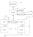
도 2를 참조하면, 디지털 전치-왜곡기(200)의 제 1 실시 예는 디지털 형태(예를 들어, 시간 샘플 당 12-14 비트)로 원하는 입력 신호 ![]()
![]()
일부 예들에서, 선택적 LTI(선형 시간 불변) 필터링 컴포넌트(212)는 업샘플링 이후의 신호를 처리한다. LTI 필터는, 예를 들어, DAC(142), LPF(144) 등의 송신 체인(140)의 엘리먼트들의 롱텀 행동을 "모방(mimic)"하도록 선택된다. 예를 들어, 고정된-계수 재구성 필터는 DAC의 제로-오더(zero-order) 홀드 특성들을 모방한다. 업샘플링되고 필터링된 입력 신호 ![]()
![]()
![]()
![]()
![]()
![]()
![]()
![]()
![]()
![]()
![]()
![]()
![]()
![]()
![]()
![]()
![]()
![]()
도 3을 참조하면, 일부 실시 예들에서, DPD(200)의 출력 ![]()
![]()
![]()
![]()
![]()
![]()
도 4를 참조하면, 다른 실시 예에서, DPD 계수들(235)은 수신 체인(430)이 출력 ![]()
![]()
![]()
![]()
![]()
![]()
도 5를 참조하면, 계수 데이터베이스(344)(도 3 참조)를 형성하는 접근법은 동작적인 사용 전에 송신 체인(140)의 분석을 이용한다. 보다 일반적으로, 송신 체인들(예를 들어, 개별적으로 제조된 부분들 사용함)의 예시들(instances)의 세트는 샘플 제조 및 상이한 부분-대-부분 변동들을 샘플링하기 위해 분석된다. 일반적으로, 상이한 테스트 신호들 ![]()
![]()
![]()
![]()
![]()
![]()
계속해서도 5를 참조하면, 송신 체인의 각각의 경우는 특정 테스트 신호들을 송신 체인(140)을 통해 전달하고, 시그니처 측정 모듈(550)을 사용하여 시그니처 값들(예를 들어, 정량적 또는 카테고리적(categorical) 값)을 결정함으로써 특성화될 수 있다. 예를 들어, 멀티-톤 테스트 신호들이 송신 체인을 통과할 수 있고, 왜곡 생성물의 크기가 측정되고 부품 시그니처의 엘리먼트들로서 기록될 수 있다. 제조 또는 다른 사전-동작 스테이지의 일부로서, 송신 체인에 대한 부품 시그니처는 그 송신 체인과 관련하여 제공되고, 예를 들어, 도 3에 도시된 부품 시그니처(343)와 같이, 동작에 사용된다. 예를 들어, 부분 시그니처는 송신 체인 또는 그 컴포넌트들에 결합되거나, 또는 그렇지 않고 연관되는, 컴퓨터 판독 가능 매체(예를 들어, 비-휘발성 반도체 메모리)에 저장될 수 있다. DPD(200)에 의해 사용될 때, 부품 시그니처는 DPD 상에 특정 기능(specific functionality)을 부여하여 송신 체인의 특정 인스턴스의 비-선형성을 보상한다.5, each case of the transmit chain conveys specific test signals through the
환경 변수들 및 시그니처 변수들은 독립적으로 또는 조합하여 사용될 수 있다는 것을 이해해야 한다. 또한, 계수 보간기(340)(예를 들어, 도 3)는 계수 모델러(560)(예를 들어, 도 5)와 호환 가능한 다양한 형태들 또는 보간 또는 근사를 구현할 수 있음을 알아야 한다. 이러한 기술은 비-필수적인 예로서 구분적(piecewise) 선형 보간의 사용을 포함할 수 있다. 환경 및 시그니처 변수들로부터의 다른 맵핑 방법은 상이한 구분적 매끄러운 함수들, 커널 접근법 등의 사용을 포함한다.It should be appreciated that environmental variables and signature variables can be used independently or in combination. It should also be noted that the coefficient interpolator 340 (e.g., FIG. 3) may implement various forms or interpolation or approximations compatible with the coefficient modeler 560 (e.g., FIG. 5). This technique may include the use of piecewise linear interpolation as a non-essential example. Other mapping methods from environment and signature variables include the use of different delimited smooth functions, kernel approaches, and the like.
도 6을 참조하면, 또 다른 실시 예는 도 3 및 도 4에 도시된 양상들, 즉 DPD 계수들(235)이 계수 데이터베이스(344) 및 환경 변수들(342) 및/또는 부품 시그니처(343)뿐만 아니라, 송신 체인(140)의 출력의 수신 체인(330)을 통해 감지되고 복조되는 피드백에 의존한다.6, another embodiment is illustrated in which the aspects shown in FIGS. 3 and 4,
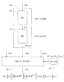
도 7을 참조하면, 다시 도 2를 참조하면, 기본 형성 엘리먼트들의 세트(220a-220s)는 도 7에 도시된 기본 형성 엘리먼트(220i)로 표현될 수 있는 엘리먼트들을 포함한다. 일반적으로, 각각의 그러한 기본 형성 엘리먼트는 대표적 변환 엘리먼트(410i) 및 필터 엘리먼트(420i)(예를 들어, LTI)를 포함한다. 변환 엘리먼트들은 일반적으로 비선형(예를 들어, 다항식) 및 메모리리스(memoryless)이고, ![]()
![]()
![]()
![]()
![]()
![]()
![]()
![]()
![]()
![]()
![]()
![]()
![]()
![]()
계속해서 도 7을 참조하면, 일부 예들에서, 기본 함수들의 비-선형 조합은 밸런싱된 다항식 계산 엘리먼트(230)를 사용하는데, 이는 다음과 같이 일반적인 형태로 표현될 수 있다:7, in some examples, the non-linear combination of basic functions uses a balanced

여기서, ![]()
![]()
![]()
![]()
![]()
![]()
![]()
![]()
![]()
![]()
![]()
![]()
![]()
![]()
![]()
![]()

이러한 기능들의 예들로는 ![]()
![]()
![]()
![]()
![]()
![]()
도 8을 참조하면, 일부 실시 예들에서, 기본 형성 블록들(220a-s)의 일부 또는 전부는 "비-다항식" 형태들을 사용할 수 있다. 예를 들어, 도 8에 도시된 바와 같이, 정규화 블록(820i)은 평균값(예를 들어, 긴 시간 스케일 쇠퇴 평균(long time scale decaying average))으로 나눔으로써 기본 값을 정규화하는 데 사용될 수 있다. 이러한 유형의 정규화는 단지 기본 형성의 비-다항식 형태의 예인 것을 인식해야 한다.8, in some embodiments, some or all of the
다시 도 2를 참조하면, 출력 ![]()
![]()
![]()
![]()
![]()
![]()
위에서 설명된 DPD의 구조는 동작 동안의 변동에 강하고, 시스템의 선형화를 유지하기 위해 동작 중에 신속하게 적응될 필요는 없다. 예를 들어, DPD에 대한 파라미터들은, 예를 들어, 시스템의 제조 또는 배치 동안 추정되는 것과 같이, 장시간의 동작 동안 한번 추정될 수 있다.The structure of the DPD described above is robust to variations during operation and does not need to be quickly adapted during operation to maintain linearization of the system. For example, parameters for DPD can be estimated once during a long time operation, e.g., as estimated during manufacture or deployment of the system.
다시 도 5를 참조하면, DPD에 대한 파라미터들 ![]()
![]()
![]()
![]()
![]()
![]()
![]()
![]()
일부 실시 예들에서, 송신 체인으로의 입력, ![]()
![]()
![]()
![]()
![]()
![]()
![]()
![]()
- ![]()
![]()
![]()
![]()
- 훈련 시퀀스 ![]()
![]()
![]()
![]()
- ![]()
![]()
![]()
![]()
![]()
![]()
- 최종 반복(![]()
![]()
![]()
![]()
![]()
![]()
대안적인 접근법에서, 수율(yield) ![]()
![]()
![]()
![]()
![]()
![]()
일부 구현 예들에서, 파라미터들 ![]()
![]()
위에서 설명된 접근법들의 구현 예들은 하드웨어, 소프트웨어, 또는 하드웨어와 소프트웨어의 조합을 사용할 수 있다. 소프트웨어는 비-일시적 기계 판독 가능 매체 상에 저장되고 프로세서에 의한 실행을 위해 매체로부터 판독되는, 범용, 특수 목적 프로세서 또는 이종 프로세서를 위한 명령을 포함할 수 있다. 명령들은 기계 레벨일 수 있거나, 또는 프로그래밍 언어 형태로 표현될 수 있다. 일부 예들에서, 송신 체인의 적어도 일부는 소프트웨어로 구현되고, DPD 접근법은 송신 체인의 그 부분을 구현하는 샘플 신호 프로세서 또는 시스템상에서 실행되는 추가 소프트웨어로서 구현된다. 일부 예들에서, 소프트웨어는 DPD의 구현에 특별히 지정된 프로세서상에서 실행된다.Implementations of the approaches described above may use hardware, software, or a combination of hardware and software. The software may include instructions for a general purpose, special purpose processor or disparate processor stored on a non-transitory machine-readable medium and read from the medium for execution by the processor. The instructions may be machine level, or may be expressed in programming language form. In some examples, at least a portion of the transmit chain is implemented in software, and the DPD approach is implemented as a sample signal processor that implements that portion of the transmit chain or as additional software running on the system. In some instances, the software runs on a processor specifically designated for the implementation of DPD.
DPD의 적어도 일부 실시 예는, 일반적으로 디지털 신호 처리를 위한 회로(예컨대, 산술 연산 회로)를 포함하는, 회로를 사용하고, 이는 위에서 설명한 특정 함수들에 전용될 수 있고(예를 들어, 주문형 집적 회로, ASIC 또는 필드 프로그래밍 가능 게이트 어레이), 및/또는 함수들을 구현하는 소프트웨어 명령들에 의해 제어될 수 있다. 일부 구현 예들에서, 컴퓨터 액세스 가능 저장 매체는 DPD(200)의 일부 또는 전부를 나타내는 데이터베이스를 포함한다. 일반적으로 말하면, 컴퓨터 액세스 가능 저장 매체는 명령들 및/또는 데이터를 컴퓨터에 제공하기 위해 사용 도중에 컴퓨터에 의해 액세스 가능한 임의의 비-일시적인 저장 매체를 포함할 수 있다. 예를 들어, 컴퓨터 액세스 가능 저장 매체는 자기 또는 광학 디스크들과 같은 저장 매체 및 반도체 메모리들을 포함할 수 있다. 일반적으로, 시스템을 나타내는 데이터베이스는 프로그램에 의해 판독될 수 있고, 시스템을 포함하는 하드웨어를 제조하기 위해, 직접 또는 간접적으로, 사용될 수 있는 데이터베이스 또는 다른 데이터 구조일 수 있다. 예를 들어, 데이터베이스는 베릴로그(Verilog) 또는 VHDL과 같은 하이 레벨 설계 언어(HDL)에서 하드웨어 기능의 행동-레벨 설명 또는 레지스터-전송-레벨(RTL) 설명일 수 있다. 본 설명은 합성 라이브러리로부터 게이트들의 리스트를 포함하는 네트리스트(netlist)를 생성하기 위해 디스크립션을 합성할 수 있는 합성 툴에 의해 판독될 수 있다. 네트리스트는 DPD를 포함하는 하드웨어의 기능성을 또한 나타내는 게이트들의 세트를 포함한다. 그 다음, 넷리스트는 필드-프로그래머블 게이트 어레이를 위한 구성 비트파일을 생성하거나, 마스크들에 적용될 기하학적 형상들을 기술하는 데이터 세트를 생성하도록 라우팅될 수 있다. 그 다음, 마스크들은 DPD에 대응하는 반도체 회로 또는 회로들을 생성하기 위해 다양한 반도체 제조 단계들에서 사용될 수 있다. 다른 예에서, 대안 적으로, 데이터베이스는 그 자체가 넷리스트(합성 라이브러리가 있거나 없음) 또는 데이터 세트일 수 있다.At least some embodiments of DPD use circuitry, generally including circuitry (e.g., arithmetic logic circuitry) for digital signal processing, which can be dedicated to the specific functions described above (e.g., Circuit, an ASIC or a field programmable gate array), and / or software instructions that implement the functions. In some implementations, the computer-accessible storage medium includes a database representing part or all of
전술한 설명은 첨부된 청구항의 범주에 의해 정의되는, 본 발명의 범위를 예시하고 제한하지 않는 것으로 이해되어야 한다. 다른 실시 예들은 하기의 청구항들의 범위 내에 있다.It is to be understood that the above description is intended to illustrate and not limit the scope of the invention, which is defined by the scope of the appended claims. Other embodiments are within the scope of the following claims.
Claims (36)
원하는 신호를 수신하는 입력;
보상된 신호를 제공하는 출력;
복수의 계수들에 대한 스토리지; 및
복수의 계수들에 따라 원하는 신호를 처리하여 상기 보상된 신호를 생성하기 위해 상기 입력 및 상기 출력에 조합된 신호 프로세서를 포함하고;
상기 신호 프로세서는 기본 조합 스테이지(basis combination stage)에 결합된 기본 형성 스테이지(basis formation stage)를 포함하고;
상기 기본 형성 스테이지는 상기 입력에 제공되는 상기 원하는 신호에 의존하는 기본 신호를 생성하도록 각각 구성된, 복수의 기본 형성 엘리먼트들을 포함하고;
상기 기본 형성 엘리먼트들 중 적어도 일부는 상기 원하는 신호의 비-선형 변환을 생성하도록 구성된 비-선형 엘리먼트, 및 비-선형 변환의 시간 필터링을 생성하도록 구성된 필터를 각각 포함하고;
상기 기본 조합 스테이지는 상기 기본 형성 엘리먼트들로부터 복수의 기본 신호들을 수용하고, 복수의 계수들에 따라 상기 기본 신호로부터 조합된 신호를 생성하도록 구성되고; 그리고
상기 디지털 보상기는 기본 조합 스테이지에 의해 생성된 상기 조합된 신호에 따라 상기 출력에서 상기 보상된 신호를 제공하도록 구성되는, 신호 체인을 위한 디지털 보상기.A digital compensator for a signal chain comprising at least one analog amplification element,
An input for receiving a desired signal;
An output providing a compensated signal;
Storage for a plurality of coefficients; And
And a signal processor coupled to the input and the output to process the desired signal according to a plurality of coefficients to produce the compensated signal;
The signal processor including a basis formation stage coupled to a basis combination stage;
The basic formation stage comprising a plurality of basic shaping elements, each configured to produce a basic signal depending on the desired signal provided to the input;
Wherein at least some of the basic shaping elements each include a non-linear element configured to produce a non-linear transformation of the desired signal and a filter configured to generate temporal filtering of the non-linear transformation;
The basic combining stage is configured to receive a plurality of base signals from the basic forming elements and to generate a combined signal from the base signal according to a plurality of coefficients; And
Wherein the digital compensator is configured to provide the compensated signal at the output in accordance with the combined signal generated by the basic combining stage.


원하는 신호를 수신하는 단계;
복수의 계수들에 따라 상기 보상된 신호를 생성하기 위해 상기 원하는 신호를 처리하는 단계; 및
상기 보상된 신호를 상기 신호 체인에 제공하는 단계를 포함하고;
상기 원하는 신호를 처리하는 단계는,
상기 원하는 신호에 각각 의존하는, 복수의 기본 신호들을 생성하는 단계를 포함하는, 기본 조합 스테이지에서 상기 원하는 신호에 의존하는 신호를 처리하는 단계 - 상기 기본 신호들의 적어도 일부의 각 기본 신호를 생성하는 단계는, 상기 원하는 신호의 비-선형 변환을 수행하는 단계 및 상기 원하는 신호의 비-선형 변환을 시간 필터링하는 단계를 포함함 - ,
조합된 신호를 생성하기 위해 복수의 계수들에 따라 복수의 기본 신호들을 결합하는 단계, 그리고
상기 조합된 신호에 따라 상기 보상된 신호를 결정하는 단계를 포함하는, 신호 체인의 디지털 보상 방법.A digital compensation method of a signal chain comprising at least one analog amplification element,
Receiving a desired signal;
Processing the desired signal to produce the compensated signal in accordance with a plurality of coefficients; And
And providing the compensated signal to the signal chain;
Wherein processing the desired signal comprises:
Processing a signal depending on the desired signal in a basic combining stage, comprising generating a plurality of basic signals, each dependent on the desired signal, - generating each basic signal of at least a portion of the basic signals Performing a non-linear transformation of the desired signal and temporally filtering the non-linear transformation of the desired signal,
Combining a plurality of base signals according to a plurality of coefficients to produce a combined signal, and
And determining the compensated signal in accordance with the combined signal.


원하는 신호를 수신하고;
복수의 계수들에 따라 보상된 신호를 생성하기 위해 상기 원하는 신호를 처리하고; 그리고
상기 보상된 신호를 신호 체인에 제공하도록 하고;
상기 원하는 신호를 처리하는 것은,
상기 원하는 신호에 각각 의존하는, 복수의 기본 신호들을 생성하는 것을 포함하는, 기본 조합 스테이지에서 상기 원하는 신호에 의존하는 신호를 처리하는 것 - 상기 기본 신호들의 적어도 일부의 각 기본 신호를 생성하는 것은, 상기 원하는 신호의 비-선형 변환을 수행하는 것 및 상기 원하는 신호의 비-선형 변환을 시간 필터링하는 것을 포함함 - ,
조합된 신호를 생성하기 위해 복수의 계수들에 따라 복수의 기본 신호들을 결합하는 것, 및
상기 조합된 신호에 따라 상기 보상된 신호를 결정하는 것을 포함하는, 명령들이 저장된 비-일시적 기계-판독 가능 매체를 포함하는 소프트웨어.17. A software product comprising a non-transient machine-readable medium on which instructions are stored, the execution of the instructions causing the data processing system to:
Receiving a desired signal;
Process the desired signal to produce a compensated signal according to a plurality of coefficients; And
Providing the compensated signal to a signal chain;
Processing the desired signal may include,
Processing a signal dependent on the desired signal in a basic combining stage, the generating of each basic signal of at least a portion of the basic signals comprising generating a plurality of fundamental signals, each dependent on the desired signal, Performing a non-linear transformation of the desired signal and temporally filtering the non-linear transformation of the desired signal,
Combining a plurality of base signals according to a plurality of coefficients to produce a combined signal, and
And determining the compensated signal in accordance with the combined signal. ≪ RTI ID = 0.0 >< / RTI >
원하는 신호를 수신하는 입력;
보상된 신호를 제공하는 출력;
복수의 계수들에 대한 스토리지; 및
복수의 계수들에 따라 원하는 신호를 처리하여 상기 보상된 신호를 생성하기 위해 상기 입력 및 상기 출력에 조합된 신호 프로세서;
상기 신호 프로세서는 기본 조합 스테이지(basis combination stage)에 결합된 기본 형성 스테이지(basis formation stage)를 포함하고;
기본 형성 스테이지는 상기 입력에 제공되는 상기 원하는 신호에 의존하는 기본 신호를 생성하도록 각각 구성된, 복수의 기본 형성 엘리먼트들을 포함하고;
상기 기본 형성 엘리먼트들 중 적어도 일부는 상기 원하는 신호의 비-선형 변환을 생성하도록 구성된 비-선형 엘리먼트, 및 비-선형 변환의 시간 필터링을 생성하도록 구성된 필터를 각각 포함하고;
상기 기본 조합 스테이지는 상기 기본 형성 엘리먼트들로부터 복수의 기본 신호들을 수용하고, 복수의 계수들에 따라 상기 기본 신호로부터 조합된 신호를 생성하도록 구성되고; 그리고
상기 디지털 보상기는 기본 조합 스테이지에 의해 생성된 상기 조합된 신호에 따라 상기 출력에서 상기 보상된 신호를 제공하도록 구성되는, 비-일시적 기계-판독 가능 매체 상에 부호화된 설계 구조.Wherein the encoded design structure on the non-transient machine-readable medium comprising elements generates a machine-executable representation of the digital compensator when processed in a computer-aided design system, The digital compensator is:
An input for receiving a desired signal;
An output providing a compensated signal;
Storage for a plurality of coefficients; And
A signal processor coupled to the input and the output to process the desired signal according to a plurality of coefficients to produce the compensated signal;
The signal processor including a basis formation stage coupled to a basis combination stage;
Wherein the basic shaping stage comprises a plurality of basic shaping elements each configured to produce a basic signal dependent on the desired signal provided to the input;
Wherein at least some of the basic shaping elements each include a non-linear element configured to produce a non-linear transformation of the desired signal and a filter configured to generate temporal filtering of the non-linear transformation;
The basic combining stage is configured to receive a plurality of base signals from the basic forming elements and to generate a combined signal from the base signal according to a plurality of coefficients; And
Wherein the digital compensator is configured to provide the compensated signal at the output in accordance with the combined signal generated by the basic combining stage.
Applications Claiming Priority (3)
| Application Number | Priority Date | Filing Date | Title |
|---|---|---|---|
| US14/953,762 US9590668B1 (en) | 2015-11-30 | 2015-11-30 | Digital compensator |
| US14/953,762 | 2015-11-30 | ||
| PCT/US2016/064127 WO2017095869A1 (en) | 2015-11-30 | 2016-11-30 | Digital compensator |
Publications (1)
| Publication Number | Publication Date |
|---|---|
| KR20180088882A true KR20180088882A (en) | 2018-08-07 |
Family
ID=57708730
Family Applications (1)
| Application Number | Title | Priority Date | Filing Date |
|---|---|---|---|
| KR1020187018592A KR20180088882A (en) | 2015-11-30 | 2016-11-30 | Digital compensator |
Country Status (6)
| Country | Link |
|---|---|
| US (3) | US9590668B1 (en) |
| EP (1) | EP3384597B1 (en) |
| JP (1) | JP6774492B2 (en) |
| KR (1) | KR20180088882A (en) |
| CN (1) | CN108702136B (en) |
| WO (1) | WO2017095869A1 (en) |
Cited By (2)
| Publication number | Priority date | Publication date | Assignee | Title |
|---|---|---|---|---|
| KR20220055417A (en) * | 2020-10-26 | 2022-05-03 | 아날로그 디바이시즈 인터내셔널 언리미티드 컴퍼니 | Configurable non-linear filter for digital pre-distortion |
| US11533070B2 (en) | 2019-12-23 | 2022-12-20 | Analog Devices International Unlimited Company | Systems and methods of compensating for narrowband distortion in power semiconductor devices |
Families Citing this family (27)
| Publication number | Priority date | Publication date | Assignee | Title |
|---|---|---|---|---|
| US9590668B1 (en) | 2015-11-30 | 2017-03-07 | NanoSemi Technologies | Digital compensator |
| US10812166B2 (en) | 2016-10-07 | 2020-10-20 | Nanosemi, Inc. | Beam steering digital predistortion |
| CN110574288A (en) | 2017-02-25 | 2019-12-13 | 纳诺塞米有限公司 | Multi-band digital predistorter |
| US10141961B1 (en) | 2017-05-18 | 2018-11-27 | Nanosemi, Inc. | Passive intermodulation cancellation |
| US10931318B2 (en) * | 2017-06-09 | 2021-02-23 | Nanosemi, Inc. | Subsampled linearization system |
| US11115067B2 (en) | 2017-06-09 | 2021-09-07 | Nanosemi, Inc. | Multi-band linearization system |
| US10581470B2 (en) | 2017-06-09 | 2020-03-03 | Nanosemi, Inc. | Linearization system |
| CN111066265A (en) * | 2017-06-09 | 2020-04-24 | 纳诺塞米有限公司 | Sub-sampling linearization system |
| WO2019014422A1 (en) | 2017-07-12 | 2019-01-17 | Nanosemi, Inc. | Monitoring systems and methods for radios implemented with digital predistortion |
| WO2019070573A1 (en) * | 2017-10-02 | 2019-04-11 | Nanosemi, Inc. | Digital predistortion adjustment based on determination of load condition characteristics |
| US10340934B1 (en) | 2017-12-18 | 2019-07-02 | Analog Devices, Inc. | Signal path linearization |
| JP7024420B2 (en) * | 2018-01-12 | 2022-02-24 | 日本電気株式会社 | Strain compensation device and strain compensation method |
| US10644657B1 (en) | 2018-05-11 | 2020-05-05 | Nanosemi, Inc. | Multi-band digital compensator for a non-linear system |
| EP3791470A1 (en) | 2018-05-11 | 2021-03-17 | Nanosemi, Inc. | Digital compensator for a non-linear system |
| US11863210B2 (en) | 2018-05-25 | 2024-01-02 | Nanosemi, Inc. | Linearization with level tracking |
| EP3804127A1 (en) | 2018-05-25 | 2021-04-14 | NanoSemi, Inc. | Digital predistortion in varying operating conditions |
| US10931238B2 (en) | 2018-05-25 | 2021-02-23 | Nanosemi, Inc. | Linearization with envelope tracking or average power tracking |
| DE112019005221T5 (en) | 2018-10-19 | 2021-07-08 | Nanosemi, Inc. | Digital multi-band compensator for a non-linear system |
| US10735013B2 (en) * | 2018-12-31 | 2020-08-04 | Tektronix, Inc. | Linear and non-linear calibration for time interleaved digital-to-analog converter |
| US10985951B2 (en) | 2019-03-15 | 2021-04-20 | The Research Foundation for the State University | Integrating Volterra series model and deep neural networks to equalize nonlinear power amplifiers |
| US10848169B2 (en) | 2019-03-20 | 2020-11-24 | Analog Devices, Inc. | Receiver signal chains with low power drivers and driver optimization |
| KR20210007277A (en) | 2019-07-10 | 2021-01-20 | 삼성전자주식회사 | Device and method for compensating nonlinearity of power amplifier |
| EP4070453A1 (en) * | 2019-12-04 | 2022-10-12 | Telefonaktiebolaget LM Ericsson (publ.) | Method and system of linearization for non-linear system |
| US10992326B1 (en) | 2020-05-19 | 2021-04-27 | Nanosemi, Inc. | Buffer management for adaptive digital predistortion |
| US11336493B1 (en) * | 2020-12-31 | 2022-05-17 | Hughes Network Systems, Llc | Dynamic transmission impairment correction for satellite systems |
| US11856528B2 (en) * | 2022-01-10 | 2023-12-26 | Qualcomm Incorporated | Techniques for temperature adaptation for digital pre-distortion factory training |
| CN116488613B (en) * | 2023-06-26 | 2024-05-28 | 深圳深浦电气有限公司 | Filtering method, device, terminal equipment and readable storage medium |
Family Cites Families (164)
| Publication number | Priority date | Publication date | Assignee | Title |
|---|---|---|---|---|
| US4979126A (en) | 1988-03-30 | 1990-12-18 | Ai Ware Incorporated | Neural network with non-linear transformations |
| FI105865B (en) | 1994-11-14 | 2000-10-13 | Nokia Mobile Phones Ltd | A method and circuit for adjusting and linearizing the transmitter signal power of a radio device |
| US5980457A (en) | 1997-11-17 | 1999-11-09 | Atl Ultrasound, Inc. | Ultrasonic transmit pulses for nonlinear ultrasonic imaging |
| US6288610B1 (en) | 1998-03-19 | 2001-09-11 | Fujitsu Limited | Method and apparatus for correcting signals, apparatus for compensating for distortion, apparatus for preparing distortion compensating data, and transmitter |
| US6240278B1 (en) | 1998-07-30 | 2001-05-29 | Motorola, Inc. | Scalar cost function based predistortion linearizing device, method, phone and basestation |
| US6052412A (en) | 1998-10-30 | 2000-04-18 | Tyco Electronics Corporation | Codec supporting PCM modem communications over a universal digital loop carrier |
| US6356146B1 (en) | 1999-07-13 | 2002-03-12 | Pmc-Sierra, Inc. | Amplifier measurement and modeling processes for use in generating predistortion parameters |
| US7158566B2 (en) | 2000-07-24 | 2007-01-02 | Eric Morgan Dowling | High-speed adaptive interconnect architecture with nonlinear error functions |
| KR20020054149A (en) | 2000-12-27 | 2002-07-06 | 엘지전자 주식회사 | Base station transmitter with digital predistorter |
| KR100408043B1 (en) | 2001-09-21 | 2003-12-01 | 엘지전자 주식회사 | Predistortion type digital linearier with digital if circuit |
| US7058369B1 (en) | 2001-11-21 | 2006-06-06 | Pmc-Sierra Inc. | Constant gain digital predistortion controller for linearization of non-linear amplifiers |
| US6885241B2 (en) | 2002-03-26 | 2005-04-26 | Her Majesty The Queen In Right Of Canada, As Represented By The Minister Of Industry | Type-based baseband predistorter function estimation technique for non-linear circuits |
| US6985704B2 (en) | 2002-05-01 | 2006-01-10 | Dali Yang | System and method for digital memorized predistortion for wireless communication |
| US8064850B2 (en) | 2002-05-01 | 2011-11-22 | Dali Systems Co., Ltd. | High efficiency linearization power amplifier for wireless communication |
| US20040076247A1 (en) | 2002-10-22 | 2004-04-22 | Wiseband Communications Ltd. | Peak-to-average power ratio modifier |
| US7266145B2 (en) | 2002-11-08 | 2007-09-04 | Scintera Networks, Inc. | Adaptive signal equalizer with adaptive error timing and precursor/postcursor configuration control |
| JP3946188B2 (en) * | 2002-12-10 | 2007-07-18 | 株式会社エヌ・ティ・ティ・ドコモ | Linear power amplification method, linear power amplifier and digital predistorter setting method thereof |
| US7170342B2 (en) | 2002-12-10 | 2007-01-30 | Ntt Docomo, Inc. | Linear power amplification method and linear power amplifier |
| US7333557B2 (en) | 2002-12-16 | 2008-02-19 | Nortel Networks Limited | Adaptive controller for linearization of transmitter with impairments |
| US20040142667A1 (en) | 2003-01-21 | 2004-07-22 | Lochhead Donald Laird | Method of correcting distortion in a power amplifier |
| US7289773B2 (en) | 2003-01-23 | 2007-10-30 | Powerwave Technologies, Inc. | Digital transmitter system employing self-generating predistortion parameter lists and adaptive controller |
| US7729668B2 (en) | 2003-04-03 | 2010-06-01 | Andrew Llc | Independence between paths that predistort for memory and memory-less distortion in power amplifiers |
| US7149257B2 (en) * | 2003-07-03 | 2006-12-12 | Powerwave Technologies, Inc. | Digital predistortion system and method for correcting memory effects within an RF power amplifier |
| US7409193B2 (en) | 2003-07-03 | 2008-08-05 | Zarbana Digital Fund Llc | Predistortion circuit for a transmit system |
| US7529652B1 (en) | 2003-10-02 | 2009-05-05 | The Mathworks, Inc. | Method for modelling and analyzing linear time invariant systems with time delays |
| US7330517B2 (en) * | 2003-11-24 | 2008-02-12 | P-Wave Ltd. | Amplifier linearization using non-linear predistortion |
| US7342976B2 (en) * | 2004-01-27 | 2008-03-11 | Crestcom, Inc. | Predistortion circuit and method for compensating A/D and other distortion in a digital RF communications transmitter |
| US7469491B2 (en) | 2004-01-27 | 2008-12-30 | Crestcom, Inc. | Transmitter predistortion circuit and method therefor |
| US7430248B2 (en) * | 2004-01-27 | 2008-09-30 | Crestcom, Inc. | Predistortion circuit and method for compensating nonlinear distortion in a digital RF communications transmitter |
| JP4255849B2 (en) | 2004-01-29 | 2009-04-15 | 株式会社エヌ・ティ・ティ・ドコモ | Power series digital predistorter |
| US7577211B2 (en) | 2004-03-01 | 2009-08-18 | Powerwave Technologies, Inc. | Digital predistortion system and method for linearizing an RF power amplifier with nonlinear gain characteristics and memory effects |
| US7336725B2 (en) * | 2004-03-03 | 2008-02-26 | Powerwave Technologies, Inc. | Digital predistortion system and method for high efficiency transmitters |
| US7095278B2 (en) | 2004-07-28 | 2006-08-22 | Nortel Networks Limited | Power amplifier arrangement and method for memory correction/linearization |
| US7599431B1 (en) | 2004-11-24 | 2009-10-06 | Xilinx, Inc. | Combined decision feedback equalization and linear equalization |
| FI20055012A0 (en) | 2005-01-07 | 2005-01-07 | Nokia Corp | Trimming a broadcast signal |
| DE102005013880B3 (en) | 2005-03-24 | 2006-04-20 | Infineon Technologies Ag | Signals predistortion method, involves selecting table from set of two tables based on determined operating condition, and selecting pre distortion coefficient from selected table based on performance word and component |
| CN100527602C (en) | 2005-06-06 | 2009-08-12 | 株式会社Ntt都科摩 | Power series type predistorter for multi-frequency bands operation |
| US7911272B2 (en) | 2007-06-19 | 2011-03-22 | Parkervision, Inc. | Systems and methods of RF power transmission, modulation, and amplification, including blended control embodiments |
| US7944991B2 (en) | 2005-10-27 | 2011-05-17 | Georgia Tech Research Corporation | Constrained clipping for peak-to-average power ratio (crest factor) reduction in multicarrier transmission systems |
| GB0601095D0 (en) | 2006-01-19 | 2006-03-01 | Cambridge Silicon Radio Ltd | Interoperation Of Terminals |
| US8170487B2 (en) | 2006-02-03 | 2012-05-01 | Qualcomm, Incorporated | Baseband transmitter self-jamming and intermodulation cancellation device |
| US7796960B1 (en) | 2006-04-04 | 2010-09-14 | Nortel Networks Limited | Signal transmitter linearization |
| US8498590B1 (en) | 2006-04-04 | 2013-07-30 | Apple Inc. | Signal transmitter linearization |
| US7876867B2 (en) | 2006-08-08 | 2011-01-25 | Qualcomm Incorporated | Intermodulation distortion detection and mitigation |
| US7561857B2 (en) * | 2006-08-30 | 2009-07-14 | Infineon Technologies Ag | Model network of a nonlinear circuitry |
| US8073073B2 (en) | 2006-10-30 | 2011-12-06 | Quantenna Communications, Inc. | Optimized clipping for peak-to-average power ratio reduction |
| KR20100014339A (en) | 2006-12-26 | 2010-02-10 | 달리 시스템즈 씨오. 엘티디. | Method and system for baseband predistortion linearization in multi-channel wideband communication systems |
| US7839951B2 (en) | 2007-04-05 | 2010-11-23 | Microelectronics Technology Inc. | Dynamic crest factor reduction system |
| US20080285640A1 (en) * | 2007-05-15 | 2008-11-20 | Crestcom, Inc. | RF Transmitter With Nonlinear Predistortion and Method Therefor |
| EP2201675B1 (en) * | 2007-10-04 | 2020-01-08 | Avago Technologies International Sales Pte. Limited | System and method for adaptive nonlinear filtering |
| US8032102B2 (en) | 2008-01-15 | 2011-10-04 | Axiom Microdevices, Inc. | Receiver second order intermodulation correction system and method |
| US8718582B2 (en) | 2008-02-08 | 2014-05-06 | Qualcomm Incorporated | Multi-mode power amplifiers |
| US9705477B2 (en) | 2008-04-30 | 2017-07-11 | Innovation Digital, LLC | Compensator for removing nonlinear distortion |
| US8369447B2 (en) * | 2008-06-04 | 2013-02-05 | Apple Inc. | Predistortion with sectioned basis functions |
| JP5104623B2 (en) | 2008-07-29 | 2012-12-19 | 富士通株式会社 | Delay amount estimation apparatus and signal transmission apparatus |
| US8412132B2 (en) | 2008-08-21 | 2013-04-02 | Freescale Semiconductor, Inc. | Techniques for adaptive predistortion direct current offset correction in a transmitter |
| JP5205182B2 (en) * | 2008-09-09 | 2013-06-05 | 株式会社日立国際電気 | Distortion compensation amplifier |
| WO2010056646A1 (en) | 2008-11-11 | 2010-05-20 | Massachusetts Institute Of Technology | An asymmetric multilevel outphasing architecture for rf amplifiers |
| US9634577B2 (en) | 2008-11-11 | 2017-04-25 | Massachusetts Institute Of Technology | Inverter/power amplifier with capacitive energy transfer and related techniques |
| WO2010056736A2 (en) | 2008-11-11 | 2010-05-20 | Axis Network Technology Ltd. | Resource efficient adaptive digital pre-distortion system |
| JP5420887B2 (en) * | 2008-12-05 | 2014-02-19 | 日本無線株式会社 | Distortion compensation device |
| US8014263B2 (en) | 2009-08-19 | 2011-09-06 | Mitsubishi Electric Research Laboratories, Inc. | Cross-talk cancellation in cooperative wireless relay networks |
| US8731005B2 (en) | 2009-10-12 | 2014-05-20 | Kathrein-Werke Kg | Absolute timing and Tx power calibration of the Tx path in a distributed system |
| US8185066B2 (en) | 2009-10-23 | 2012-05-22 | Sony Mobile Communications Ab | Multimode power amplifier with predistortion |
| JP5334318B2 (en) | 2009-11-30 | 2013-11-06 | ルネサスエレクトロニクス株式会社 | Semiconductor integrated circuit for communication and operation method thereof |
| US8290086B2 (en) | 2009-12-09 | 2012-10-16 | Tamal Bose | Efficient outphasing transmitter |
| US8351877B2 (en) | 2010-12-21 | 2013-01-08 | Dali Systems Co. Ltfd. | Multi-band wideband power amplifier digital predistorition system and method |
| US8351543B2 (en) | 2009-12-21 | 2013-01-08 | Ubidyne, Inc. | Active antenna array with modulator-based pre-distortion |
| JP2013519307A (en) | 2010-02-03 | 2013-05-23 | マサチューセッツ インスティテュート オブ テクノロジー | Radio frequency (RF) amplifier circuit and related techniques |
| US8446979B1 (en) | 2010-03-02 | 2013-05-21 | Pmc-Sierra, Inc. | Predistortion with integral crest-factor reduction and reduced observation bandwidth |
| US20110235734A1 (en) | 2010-03-26 | 2011-09-29 | Peter Kenington | Active antenna array having a single dpd lineariser and a method for predistortion of radio signals |
| IL212379A0 (en) | 2010-04-19 | 2011-06-30 | Designart Networks Ltd | A method and apparatus crest-factor reduction in telecommunications systems |
| US8203386B2 (en) | 2010-05-04 | 2012-06-19 | Nxp B.V. | Reconfigurable outphasing Chireix amplifiers and methods |
| US8174322B2 (en) | 2010-05-04 | 2012-05-08 | Nxp B.V. | Power control of reconfigurable outphasing chireix amplifiers and methods |
| US9363068B2 (en) * | 2010-08-03 | 2016-06-07 | Intel Corporation | Vector processor having instruction set with sliding window non-linear convolutional function |
| CN102387579B (en) | 2010-09-03 | 2016-01-20 | 中兴通讯股份有限公司 | The Poewr control method of cognitive radio system and device |
| US8619903B2 (en) | 2010-10-14 | 2013-12-31 | Kathrein-Werke Kg | Crest factor reduction for a multicarrier-signal with spectrally shaped single-carrier cancelation pulses |
| US8489047B2 (en) | 2010-11-02 | 2013-07-16 | Crestcom, Inc. | Transmitter linearized using bias deviation gain adjustment and method therefor |
| US8615208B2 (en) | 2010-11-02 | 2013-12-24 | Crestcom, Inc. | Transmitter linearized in response to signal magnitude derivative parameter and method therefor |
| US8576941B2 (en) * | 2010-11-16 | 2013-11-05 | Telefonaktiebolaget Lm Ericsson (Publ) | Configurable basis-function generation for nonlinear modeling |
| US8390376B2 (en) * | 2010-11-16 | 2013-03-05 | Telefonaktiebolaget Lm Ericsson (Publ) | Non-linear model with tap output normalization |
| WO2012066383A1 (en) * | 2010-11-16 | 2012-05-24 | Telefonaktiebolaget Lm Ericsson (Publ) | Orthogonal basis function set for ditigal predistorter |
| JP5556643B2 (en) | 2010-12-17 | 2014-07-23 | 富士通株式会社 | Amplifying device and distortion compensation method |
| JP5658552B2 (en) | 2010-12-20 | 2015-01-28 | キヤノン株式会社 | Display control apparatus, control method therefor, program, and recording medium |
| US8644437B2 (en) | 2011-01-07 | 2014-02-04 | Massachusetts Institute Of Technology | Digital compensation of a nonlinear system |
| US9184710B2 (en) | 2011-02-09 | 2015-11-10 | Intel Corporation | Digital predistortion of a power amplifier for signals comprising widely spaced carriers |
| US8908751B2 (en) | 2011-02-28 | 2014-12-09 | Intel Mobile Communications GmbH | Joint adaptive bias point adjustment and digital pre-distortion for power amplifier |
| US8537041B2 (en) | 2011-05-12 | 2013-09-17 | Andrew Llc | Interpolation-based digital pre-distortion architecture |
| US8711976B2 (en) | 2011-05-12 | 2014-04-29 | Andrew Llc | Pre-distortion architecture for compensating non-linear effects |
| US9026064B2 (en) | 2011-05-20 | 2015-05-05 | Telefonaktiebolaget L M Ericsson (Publ) | Dynamic cancellation of passive intermodulation interference |
| US8519789B2 (en) * | 2011-08-03 | 2013-08-27 | Scintera Networks, Inc. | Pre-distortion for fast power transient waveforms |
| US8767869B2 (en) | 2011-08-18 | 2014-07-01 | Qualcomm Incorporated | Joint linear and non-linear cancellation of transmit self-jamming interference |
| US9210009B2 (en) | 2011-09-15 | 2015-12-08 | Intel Corporation | Digital pre-distortion filter system and method |
| US8391809B1 (en) | 2011-10-13 | 2013-03-05 | Futurewei Technologies, Inc. | System and method for multi-band predistortion |
| US8817859B2 (en) | 2011-10-14 | 2014-08-26 | Fadhel Ghannouchi | Digital multi-band predistortion linearizer with nonlinear subsampling algorithm in the feedback loop |
| KR20140092852A (en) * | 2011-10-27 | 2014-07-24 | 엘에스아이 코포레이션 | Vector processor having instruction set with vector convolution function for fir filtering |
| US9215120B2 (en) | 2011-12-21 | 2015-12-15 | Telefonaktiebolaget L M Ericsson (Publ) | Multi-band crest factor reduction |
| US9374044B2 (en) * | 2011-12-21 | 2016-06-21 | Telefonaktiebolaget L M Ericsson (Publ) | Architecture of nonlinear RF filter-based transmitter |
| CN102594749A (en) | 2012-02-28 | 2012-07-18 | 中兴通讯股份有限公司 | Digital pre-distortion processing method and device |
| US8731105B2 (en) * | 2012-03-22 | 2014-05-20 | Telefonaktiebolaget L M Ericsson (Publ) | Multi-rate filter and filtering method for digital pre-distorters |
| JP5918439B2 (en) | 2012-03-29 | 2016-05-18 | ニヴァロックス−ファー ソシエテ アノニム | Flexible escape mechanism with balance without rollers |
| GB2500708B (en) | 2012-03-30 | 2016-04-13 | Nujira Ltd | Determination of envelope shaping and signal path predistortion of an ET amplification stage using device characterisation data |
| WO2013170116A2 (en) | 2012-05-10 | 2013-11-14 | Massachusetts Institute Of Technology | Fixed point, piece-wise-linear fitting technique and related circuits |
| US8787494B2 (en) | 2012-06-11 | 2014-07-22 | Telefonaktiebolaget L M Ericsson (Publ) | Modeling digital predistorter |
| US9014299B2 (en) | 2012-12-07 | 2015-04-21 | Maxim Integrated Products, Inc. | Digital pre-distortion system for radio frequency transmitters with reduced sampling rate in observation loop |
| US8917792B2 (en) | 2012-12-12 | 2014-12-23 | Motorola Mobility Llc | Method and apparatus for the cancellation of intermodulation and harmonic distortion in a baseband receiver |
| IL223619A (en) | 2012-12-13 | 2017-08-31 | Elta Systems Ltd | System and method for coherent processing of signals of a plurality of phased arrays |
| US8897352B2 (en) | 2012-12-20 | 2014-11-25 | Nvidia Corporation | Multipass approach for performing channel equalization training |
| US9680434B2 (en) | 2012-12-28 | 2017-06-13 | Mediatek, Inc. | Method and apparatus for calibrating an envelope tracking system |
| CN103051574B (en) | 2013-01-16 | 2016-05-11 | 大唐移动通信设备有限公司 | Digital pre-distortion processing method and system |
| US8989307B2 (en) | 2013-03-05 | 2015-03-24 | Qualcomm Incorporated | Power amplifier system including a composite digital predistorter |
| US20140274105A1 (en) | 2013-03-14 | 2014-09-18 | Qualcomm Incorporated | Systems and methods for coexistence in wlan and lte communications |
| US9595920B2 (en) | 2013-03-22 | 2017-03-14 | Massachusette Institute Of Technology | Hardware-efficient compensator for outphasing power amplifiers |
| KR101975830B1 (en) | 2013-04-02 | 2019-05-09 | 한국전자통신연구원 | Beam forming device and method for forming beam thereof |
| CA2909595A1 (en) | 2013-04-17 | 2014-10-23 | Wilus Institute Of Standards And Technology Inc. | Method and apparatus for processing video signal |
| US9214969B2 (en) | 2013-05-09 | 2015-12-15 | King Fahd University Of Petroleum And Minerals | Scalable digital predistortion system |
| CN105531925B (en) | 2013-05-20 | 2018-10-23 | 美国亚德诺半导体公司 | Digitization system linearizes |
| US9252718B2 (en) | 2013-05-22 | 2016-02-02 | Telefonaktiebolaget L M Ericsson (Publ) | Low complexity digital predistortion for concurrent multi-band transmitters |
| US9385762B2 (en) | 2013-05-22 | 2016-07-05 | Telefonaktiebolaget L M Ericsson (Publ) | Linearization of intermodulation bands for concurrent dual-band power amplifiers |
| US9331882B2 (en) | 2013-06-05 | 2016-05-03 | Telefonaktiebolaget L M Ericsson (Publ) | Crest factor reduction of carrier aggregated signals |
| CN103414671B (en) * | 2013-07-16 | 2016-12-28 | 清华大学 | 2D-DPD iteration based on unit basic function cuts down algorithm and application |
| CN104301268B (en) | 2013-07-19 | 2019-05-21 | 中兴通讯股份有限公司 | Multichannel pre-distortion method and device |
| US8976641B2 (en) | 2013-08-09 | 2015-03-10 | Kumu Networks, Inc. | Systems and methods for non-linear digital self-interference cancellation |
| GB2519361B (en) | 2013-10-21 | 2015-09-16 | Nujira Ltd | Reduced bandwidth of signal in an envelope path for envelope tracking system |
| DE102013114797B4 (en) | 2013-12-23 | 2021-06-10 | Apple Inc. | Transceiver device and method for generating a compensation signal |
| WO2015107392A1 (en) | 2014-01-16 | 2015-07-23 | Telefonaktiebolaget L M Ericsson (Publ) | Systems and methods for basis function orthogonalization for digital predistortion |
| US9184784B2 (en) | 2014-03-10 | 2015-11-10 | Texas Instruments Incorporated | Method and apparatus for digital predistortion for a switched mode power amplifier |
| GB2525173B (en) | 2014-04-08 | 2016-08-31 | Analog Devices Global | Active antenna system and methods of determining intermodulation distortion performance |
| US10333474B2 (en) | 2014-05-19 | 2019-06-25 | Skyworks Solutions, Inc. | RF transceiver front end module with improved linearity |
| US9337782B1 (en) | 2014-05-21 | 2016-05-10 | Altera Corporation | Methods and apparatus for adjusting transmit signal clipping thresholds |
| CN106464280B (en) | 2014-05-27 | 2019-02-12 | 瑞典爱立信有限公司 | For controlling the method and radio node of wireless radio transmission |
| US9252821B2 (en) | 2014-06-27 | 2016-02-02 | Freescale Semiconductor, Inc. | Adaptive high-order nonlinear function approximation using time-domain volterra series to provide flexible high performance digital pre-distortion |
| US9628119B2 (en) | 2014-06-27 | 2017-04-18 | Nxp Usa, Inc. | Adaptive high-order nonlinear function approximation using time-domain volterra series to provide flexible high performance digital pre-distortion |
| US9226189B1 (en) | 2014-08-18 | 2015-12-29 | Nokia Solutions And Networks Oy | Monitoring health of a predistortion system |
| US9735741B2 (en) | 2014-08-28 | 2017-08-15 | Analog Devices Global | Receivers for digital predistortion |
| US9564876B2 (en) | 2014-09-22 | 2017-02-07 | Nanosemi, Inc. | Digital compensation for a non-linear analog receiver |
| US9907085B2 (en) | 2014-09-26 | 2018-02-27 | Avago Technologies General Ip (Singapore) Pte. Ltd. | WIFI-coordinated LAA-LTE |
| JP6442053B2 (en) | 2014-10-31 | 2018-12-19 | 華為技術有限公司Huawei Technologies Co.,Ltd. | Curve fitting circuit, analog predistorter, and radio frequency signal transmitter |
| EP3197113B1 (en) | 2014-11-14 | 2020-06-03 | Huawei Technologies Co. Ltd. | Analog predistorter core module and analog predistorter system |
| US9130628B1 (en) | 2014-12-24 | 2015-09-08 | Freescale Semiconductor, Inc. | Digital pre-distorter |
| CN106797356B (en) * | 2014-12-29 | 2020-07-07 | 华为技术有限公司 | Control method and device for digital predistortion correction coefficient |
| US9825360B2 (en) | 2015-01-19 | 2017-11-21 | Raytheon Company | Side lobe modulation system and related techniques |
| US9590664B2 (en) | 2015-02-16 | 2017-03-07 | Telefonaktiebolaget Lm Ericsson (Publ) | Method to improve active antenna system performance in the presence of mutual coupling |
| US9998241B2 (en) | 2015-02-19 | 2018-06-12 | Mediatek Inc. | Envelope tracking (ET) closed-loop on-the-fly calibration |
| US9509350B1 (en) | 2015-06-11 | 2016-11-29 | Infineon Technologies Ag | Devices and methods for adaptive crest factor reduction in dynamic predistortion |
| US9590567B2 (en) | 2015-07-02 | 2017-03-07 | Xilinx, Inc. | Moving mean and magnitude dual path digital predistortion |
| JP2017059963A (en) | 2015-09-15 | 2017-03-23 | 富士通株式会社 | Radio equipment and distortion cancellation method |
| US9673847B1 (en) | 2015-11-25 | 2017-06-06 | Analog Devices, Inc. | Apparatus and methods for transceiver calibration |
| US9590668B1 (en) | 2015-11-30 | 2017-03-07 | NanoSemi Technologies | Digital compensator |
| CN105634539B (en) | 2015-12-31 | 2018-10-30 | 华为技术有限公司 | A kind of interference elimination method and device |
| US9749161B1 (en) | 2016-02-23 | 2017-08-29 | Nxp Usa, Inc. | Fixed-point conjugate gradient digital pre-distortion (DPD) adaptation |
| US10033413B2 (en) | 2016-05-19 | 2018-07-24 | Analog Devices Global | Mixed-mode digital predistortion |
| CN110574288A (en) | 2017-02-25 | 2019-12-13 | 纳诺塞米有限公司 | Multi-band digital predistorter |
| US9935810B1 (en) | 2017-03-07 | 2018-04-03 | Xilinx, Inc. | Method and apparatus for model identification and predistortion |
| US10141961B1 (en) | 2017-05-18 | 2018-11-27 | Nanosemi, Inc. | Passive intermodulation cancellation |
| US9973370B1 (en) | 2017-06-06 | 2018-05-15 | Intel IP Corporation | Memory predistortion in bandwidth limited envelope tracking |
| US10581470B2 (en) | 2017-06-09 | 2020-03-03 | Nanosemi, Inc. | Linearization system |
| KR102425578B1 (en) | 2017-08-08 | 2022-07-26 | 삼성전자주식회사 | Method and apparatus for recognizing an object |
| US10469109B2 (en) | 2017-09-19 | 2019-11-05 | Qualcomm Incorporated | Predistortion for transmitter with array |
| US10079699B1 (en) | 2017-10-02 | 2018-09-18 | Cypress Semiconductor Corporation | Stable modulation index calibration and dynamic control |
| US10644657B1 (en) | 2018-05-11 | 2020-05-05 | Nanosemi, Inc. | Multi-band digital compensator for a non-linear system |
| EP3791470A1 (en) | 2018-05-11 | 2021-03-17 | Nanosemi, Inc. | Digital compensator for a non-linear system |
| EP3804127A1 (en) | 2018-05-25 | 2021-04-14 | NanoSemi, Inc. | Digital predistortion in varying operating conditions |
| US10931238B2 (en) | 2018-05-25 | 2021-02-23 | Nanosemi, Inc. | Linearization with envelope tracking or average power tracking |
-
2015
- 2015-11-30 US US14/953,762 patent/US9590668B1/en active Active
-
2016
- 2016-11-30 WO PCT/US2016/064127 patent/WO2017095869A1/en active Application Filing
- 2016-11-30 KR KR1020187018592A patent/KR20180088882A/en unknown
- 2016-11-30 EP EP16820391.7A patent/EP3384597B1/en active Active
- 2016-11-30 JP JP2018526946A patent/JP6774492B2/en not_active Expired - Fee Related
- 2016-11-30 CN CN201680080259.9A patent/CN108702136B/en active Active
-
2018
- 2018-05-30 US US15/992,614 patent/US10404296B2/en active Active
-
2019
- 2019-08-30 US US16/556,659 patent/US10862517B2/en active Active
Cited By (3)
| Publication number | Priority date | Publication date | Assignee | Title |
|---|---|---|---|---|
| US11533070B2 (en) | 2019-12-23 | 2022-12-20 | Analog Devices International Unlimited Company | Systems and methods of compensating for narrowband distortion in power semiconductor devices |
| KR20220055417A (en) * | 2020-10-26 | 2022-05-03 | 아날로그 디바이시즈 인터내셔널 언리미티드 컴퍼니 | Configurable non-linear filter for digital pre-distortion |
| US11563409B2 (en) | 2020-10-26 | 2023-01-24 | Analog Devices International Unlimited Company | Configurable non-linear filter for digital pre-distortion |
Also Published As
| Publication number | Publication date |
|---|---|
| EP3384597B1 (en) | 2020-08-26 |
| CN108702136B (en) | 2022-05-10 |
| EP3384597A1 (en) | 2018-10-10 |
| JP2019500782A (en) | 2019-01-10 |
| US20200067543A1 (en) | 2020-02-27 |
| JP6774492B2 (en) | 2020-10-21 |
| US10862517B2 (en) | 2020-12-08 |
| CN108702136A (en) | 2018-10-23 |
| US9590668B1 (en) | 2017-03-07 |
| US20190007075A1 (en) | 2019-01-03 |
| WO2017095869A1 (en) | 2017-06-08 |
| US10404296B2 (en) | 2019-09-03 |
| WO2017095869A8 (en) | 2017-08-10 |
Similar Documents
| Publication | Publication Date | Title |
|---|---|---|
| KR20180088882A (en) | Digital compensator | |
| US10523159B2 (en) | Digital compensator for a non-linear system | |
| US11171614B2 (en) | Multi-band digital compensator for a non-linear system | |
| US9647717B2 (en) | Digital pre-distortion parameter obtaining method and pre-distortion system | |
| US20200186103A1 (en) | Polyphase digital signal predistortion in radio transmitter | |
| CN1954490A (en) | Adaptive predistortion method and device | |
| AU2010364181A1 (en) | Joint process estimator with variable tap delay line for use in power amplifier digital predistortion | |
| US8842033B1 (en) | Dynamic linearity corrector for digital-to-analog converters | |
| Zhu | Behavioral modeling for digital predistortion of RF power amplifiers: from Volterra series to CPWL functions | |
| EP3007354B1 (en) | Distortion compensation apparatus and wireless communication apparatus | |
| Vansebrouck et al. | Fully-digital blind compensation of non-linear distortions in wideband receivers | |
| CN113659937B (en) | Pre-distortion processing method and device, communication equipment and storage medium | |
| US10097141B1 (en) | Digital predistortion tailored to specified frequencies in the power amplifier (PA) output spectrum | |
| CN103929212A (en) | Broadband receiver nonlinear blind recognition and compensation method | |
| KR101464753B1 (en) | Method for extracting nonlinear model parameter of wideband signal using narrowband signal, apparatus and method for digital predistortering its using | |
| Tripathi et al. | Analysing digital predistortion technique for computation‐efficient power amplifier linearisation in the presence of measurement noise | |
| CN113196653B (en) | Multiband digital compensator for nonlinear systems | |
| Li et al. | A new sparse design framework for broadband power amplifier behavioral modeling and digital predistortion | |
| KR100983599B1 (en) | Digital predistortion device and its method of harmonic band signal | |
| Shan et al. | Spectral sensitivity of predistortion linearizer architectures to filter ripple | |
| Yang et al. | Frequency domain data based model extraction for band‐limited digital predistortion of wideband RF power amplifiers | |
| Cheng et al. | Digital predistortion for concurrent dual-band transmitter using a 2D-LUT based Hammerstein architecture | |
| Pham et al. | A subsampled adaptive subband digital predistortion algorithm | |
| KR20100016806A (en) | Digital predistorter and method using extension memory polynomial | |
| JP2014107806A (en) | Amplification device, distortion compensation method and distortion compensation program |