KR20180077328A - Hose clamp with flat spring liner - Google Patents
Hose clamp with flat spring liner Download PDFInfo
- Publication number
- KR20180077328A KR20180077328A KR1020187018510A KR20187018510A KR20180077328A KR 20180077328 A KR20180077328 A KR 20180077328A KR 1020187018510 A KR1020187018510 A KR 1020187018510A KR 20187018510 A KR20187018510 A KR 20187018510A KR 20180077328 A KR20180077328 A KR 20180077328A
- Authority
- KR
- South Korea
- Prior art keywords
- spring liner
- liner
- band
- hose
- spring
- Prior art date
Links
- 230000002093 peripheral effect Effects 0.000 claims description 17
- 238000000034 method Methods 0.000 claims description 15
- 230000006835 compression Effects 0.000 claims description 8
- 238000007906 compression Methods 0.000 claims description 8
- 230000008878 coupling Effects 0.000 claims 1
- 238000010168 coupling process Methods 0.000 claims 1
- 238000005859 coupling reaction Methods 0.000 claims 1
- 230000000052 comparative effect Effects 0.000 description 11
- 239000000463 material Substances 0.000 description 9
- 230000007423 decrease Effects 0.000 description 7
- 230000000694 effects Effects 0.000 description 7
- 238000007789 sealing Methods 0.000 description 5
- 230000007246 mechanism Effects 0.000 description 4
- 238000004519 manufacturing process Methods 0.000 description 3
- 239000000203 mixture Substances 0.000 description 3
- 230000008569 process Effects 0.000 description 3
- 239000000758 substrate Substances 0.000 description 3
- 239000012530 fluid Substances 0.000 description 2
- 230000009467 reduction Effects 0.000 description 2
- 238000003466 welding Methods 0.000 description 2
- 238000012935 Averaging Methods 0.000 description 1
- 230000001154 acute effect Effects 0.000 description 1
- 239000000853 adhesive Substances 0.000 description 1
- 230000001070 adhesive effect Effects 0.000 description 1
- 238000010276 construction Methods 0.000 description 1
- 238000009826 distribution Methods 0.000 description 1
- 230000007774 longterm Effects 0.000 description 1
- 239000000314 lubricant Substances 0.000 description 1
- 239000002184 metal Substances 0.000 description 1
- 230000004048 modification Effects 0.000 description 1
- 238000012986 modification Methods 0.000 description 1
- 230000002040 relaxant effect Effects 0.000 description 1
- 230000004044 response Effects 0.000 description 1
- 239000000126 substance Substances 0.000 description 1
- 238000006467 substitution reaction Methods 0.000 description 1
- 230000007704 transition Effects 0.000 description 1
- 239000004636 vulcanized rubber Substances 0.000 description 1
Images


Classifications
-
- F—MECHANICAL ENGINEERING; LIGHTING; HEATING; WEAPONS; BLASTING
- F16—ENGINEERING ELEMENTS AND UNITS; GENERAL MEASURES FOR PRODUCING AND MAINTAINING EFFECTIVE FUNCTIONING OF MACHINES OR INSTALLATIONS; THERMAL INSULATION IN GENERAL
- F16L—PIPES; JOINTS OR FITTINGS FOR PIPES; SUPPORTS FOR PIPES, CABLES OR PROTECTIVE TUBING; MEANS FOR THERMAL INSULATION IN GENERAL
- F16L33/00—Arrangements for connecting hoses to rigid members; Rigid hose connectors, i.e. single members engaging both hoses
- F16L33/02—Hose-clips
- F16L33/08—Hose-clips in which a worm coacts with a part of the hose-encircling member that is toothed like a worm-wheel
-
- F—MECHANICAL ENGINEERING; LIGHTING; HEATING; WEAPONS; BLASTING
- F16—ENGINEERING ELEMENTS AND UNITS; GENERAL MEASURES FOR PRODUCING AND MAINTAINING EFFECTIVE FUNCTIONING OF MACHINES OR INSTALLATIONS; THERMAL INSULATION IN GENERAL
- F16B—DEVICES FOR FASTENING OR SECURING CONSTRUCTIONAL ELEMENTS OR MACHINE PARTS TOGETHER, e.g. NAILS, BOLTS, CIRCLIPS, CLAMPS, CLIPS OR WEDGES; JOINTS OR JOINTING
- F16B2/00—Friction-grip releasable fastenings
- F16B2/02—Clamps, i.e. with gripping action effected by positive means other than the inherent resistance to deformation of the material of the fastening
- F16B2/06—Clamps, i.e. with gripping action effected by positive means other than the inherent resistance to deformation of the material of the fastening external, i.e. with contracting action
- F16B2/065—Clamps, i.e. with gripping action effected by positive means other than the inherent resistance to deformation of the material of the fastening external, i.e. with contracting action using screw-thread elements
-
- F—MECHANICAL ENGINEERING; LIGHTING; HEATING; WEAPONS; BLASTING
- F16—ENGINEERING ELEMENTS AND UNITS; GENERAL MEASURES FOR PRODUCING AND MAINTAINING EFFECTIVE FUNCTIONING OF MACHINES OR INSTALLATIONS; THERMAL INSULATION IN GENERAL
- F16B—DEVICES FOR FASTENING OR SECURING CONSTRUCTIONAL ELEMENTS OR MACHINE PARTS TOGETHER, e.g. NAILS, BOLTS, CIRCLIPS, CLAMPS, CLIPS OR WEDGES; JOINTS OR JOINTING
- F16B2/00—Friction-grip releasable fastenings
- F16B2/02—Clamps, i.e. with gripping action effected by positive means other than the inherent resistance to deformation of the material of the fastening
- F16B2/06—Clamps, i.e. with gripping action effected by positive means other than the inherent resistance to deformation of the material of the fastening external, i.e. with contracting action
- F16B2/08—Clamps, i.e. with gripping action effected by positive means other than the inherent resistance to deformation of the material of the fastening external, i.e. with contracting action using bands
-
- F—MECHANICAL ENGINEERING; LIGHTING; HEATING; WEAPONS; BLASTING
- F16—ENGINEERING ELEMENTS AND UNITS; GENERAL MEASURES FOR PRODUCING AND MAINTAINING EFFECTIVE FUNCTIONING OF MACHINES OR INSTALLATIONS; THERMAL INSULATION IN GENERAL
- F16L—PIPES; JOINTS OR FITTINGS FOR PIPES; SUPPORTS FOR PIPES, CABLES OR PROTECTIVE TUBING; MEANS FOR THERMAL INSULATION IN GENERAL
- F16L33/00—Arrangements for connecting hoses to rigid members; Rigid hose connectors, i.e. single members engaging both hoses
- F16L33/02—Hose-clips
- F16L33/10—Hose-clips with a substantially-radial tightening member
-
- Y—GENERAL TAGGING OF NEW TECHNOLOGICAL DEVELOPMENTS; GENERAL TAGGING OF CROSS-SECTIONAL TECHNOLOGIES SPANNING OVER SEVERAL SECTIONS OF THE IPC; TECHNICAL SUBJECTS COVERED BY FORMER USPC CROSS-REFERENCE ART COLLECTIONS [XRACs] AND DIGESTS
- Y10—TECHNICAL SUBJECTS COVERED BY FORMER USPC
- Y10T—TECHNICAL SUBJECTS COVERED BY FORMER US CLASSIFICATION
- Y10T24/00—Buckles, buttons, clasps, etc.
- Y10T24/14—Bale and package ties, hose clamps
- Y10T24/1412—Bale and package ties, hose clamps with tighteners
- Y10T24/1427—Worm and tooth
-
- Y—GENERAL TAGGING OF NEW TECHNOLOGICAL DEVELOPMENTS; GENERAL TAGGING OF CROSS-SECTIONAL TECHNOLOGIES SPANNING OVER SEVERAL SECTIONS OF THE IPC; TECHNICAL SUBJECTS COVERED BY FORMER USPC CROSS-REFERENCE ART COLLECTIONS [XRACs] AND DIGESTS
- Y10—TECHNICAL SUBJECTS COVERED BY FORMER USPC
- Y10T—TECHNICAL SUBJECTS COVERED BY FORMER US CLASSIFICATION
- Y10T24/00—Buckles, buttons, clasps, etc.
- Y10T24/14—Bale and package ties, hose clamps
- Y10T24/1412—Bale and package ties, hose clamps with tighteners
- Y10T24/1441—Tangential screw
-
- Y—GENERAL TAGGING OF NEW TECHNOLOGICAL DEVELOPMENTS; GENERAL TAGGING OF CROSS-SECTIONAL TECHNOLOGIES SPANNING OVER SEVERAL SECTIONS OF THE IPC; TECHNICAL SUBJECTS COVERED BY FORMER USPC CROSS-REFERENCE ART COLLECTIONS [XRACs] AND DIGESTS
- Y10—TECHNICAL SUBJECTS COVERED BY FORMER USPC
- Y10T—TECHNICAL SUBJECTS COVERED BY FORMER US CLASSIFICATION
- Y10T24/00—Buckles, buttons, clasps, etc.
- Y10T24/14—Bale and package ties, hose clamps
- Y10T24/1457—Metal bands
Abstract
본 발명은 내측면을 가진 환형 밴드, 인장 수단, 및 환형 스프링 라이너를 포함하는 개선된 호스 클램프에 관한 것으로서, 상기 스프링 라이너는 라이너의 에지 가까이에 주변 숄더 및 밴드의 내측면보다 더 작은 폭을 가지며 상기 숄더보다 더 작은 주변을 가진 중앙의 원통형의 평평한 접촉 부분을 포함한다. 상기 숄더는 상기 내측면과 접하도록 구성되며 접촉 부분은 클램프고정되어야 하는 호스 또는 그 외의 물품과 접촉하도록 구성된다. The present invention relates to an improved hose clamp comprising an annular band having an inner surface, a tensioning means and an annular spring liner, wherein the spring liner has a width that is nearer the edge of the liner than the inner shoulder and the inner side of the band And a central, cylindrical, flat contact portion having a periphery smaller than the shoulder. The shoulder is configured to contact the inner surface and the contact portion is configured to contact a hose or other article to be clamped.
Description
본 발명은 2011년 7월 21일에 출원되고 발명의 명칭이 "HOSE CLAMP WITH FLAT SPRING LINER"인 미국 특허출원번호 13/188,093호를 기초로 우선권을 주장하고 있는데, 이 미국 특허출원은 본 명세서에서 참조문헌으로서 인용된다. The present invention is based on U.S. Patent Application No. 13 / 188,093, filed July 21, 2011, entitled " HOSE CLAMP WITH FLAT SPRING LINER ", which is incorporated herein by reference in its entirety Quot; is incorporated herein by reference.
본 발명은 일반적으로 호스 클램프 조립체에 관한 것으로서, 보다 구체적으로는, 호스 클램프 조립체와 결합된 스프링 라이너 및 중앙의 평평한 호스-접촉 부분이 있는 스프링 라이너에 관한 것이다. The present invention relates generally to a hose clamp assembly, and more particularly, to a spring liner with a hose clamp assembly and a spring liner with a central, flat hose-contacting portion.
가령, 예를 들어, 자동차 업계에서, 호스와 피팅(fitting) 또는 커넥터(본 명세서에서는, 피팅(fitting)으로 지칭됨)를 함께 결합하기 위하여, 호스 클램프(hose clamp)가 일반적으로 사용된다. 호스 클램프, 호스 및 피팅은 위에서 언급한 구성요소들의 열 특성에 따라 시스템 온도 및 주변 온도에서의 변동에 반응한다. 이러한 구성요소들의 열팽창계수(thermal expansion coefficient)가 서로 다르기 때문에, 클램핑 힘(clamping force)이 열-유도 방식으로 감소되고(thermally-induced reductions) 이에 따라 유체 혹은 가스가 누출될 가능성이 생길 수 있다. 또한, 크리프(creep), 압축 변형(compression set) 또는 훼손으로 인해 시간이 지남에 따라 호스 재료의 탄성력이 변하면 클램핑 힘이 감소하여 유체가 유출될 가능성이 생길 수 있다. For example, in the automotive industry, a hose clamp is commonly used to join together a hose and a fitting or connector (referred to herein as a fitting). Hose clamps, hoses and fittings respond to variations in system and ambient temperatures, depending on the thermal properties of the components mentioned above. Since the thermal expansion coefficients of these components are different, the clamping force may be thermally-induced reductions and thus the possibility of fluid or gas leakage. Also, as the elasticity of the hose material changes over time due to creep, compression set, or damage, the clamping force may decrease and the fluid may leak out.
호스 클램프와 함께 사용되는 다양한 타입의 스프링 라이너가 알려져 있다. 미국 특허번호 7,178,204호 및 7,302,741호는 대표적인 종래 기술을 기술하고 있는데, 사이에 외부 방향으로 돌출되는 리지(ridge)와 함께 2개의 내부 방향으로 돌출되는 리지를 가진 스프링 라이너가 기술된다. 이 리지들은 호스 내에 매우 높은 2개의 압축 영역을 형성하며, 중앙의 리지 영역은 더 작은 압축 영역을 형성한다. Various types of spring liners for use with hose clamps are known. U.S. Patent Nos. 7,178,204 and 7,302,741 describe representative prior arts, wherein a spring liner is described having two inwardly projecting ridges with ridges protruding outwardly therebetween. These ridges form two very high compression zones in the hose, and the middle ridge zone forms a smaller compression zone.
본 발명은 동일한 출원인에 의해 2011년 7월 21일에 출원되고 발명의 명칭이 "HOSE CLAMP WITH RIPPLED SPRING LINER"인 미국 특허출원번호 13/188,103호의 동시계속출원으로서, 이 미국 특허출원도 본 명세서에서 참조문헌으로서 인용된다. This application is a continuation-in-part of U.S. Patent Application No. 13 / 188,103, filed July 21, 2011, entitled " HOSE CLAMP WITH RIPPLED SPRING LINER " Quot; is incorporated herein by reference.
본 발명의 한 형태는 호스 클램프가 탄성 특성에서의 변동 및 하부에 배열된 호스 및 피팅의 직경 변경에 대해 자체-상쇄할(self-compensate) 수 있게 하는 개선된 스프링 라이너를 제공하는 것이다. 본 발명은 호스 클램프용 환형 스프링 라이너에 관한 것으로서, 상기 스프링 라이너는 상기 라이너의 각각의 에지(edge) 가까이에 있는 주변 숄더(circumferential shoulder) 및 두 숄더 사이에 평평한 접촉 부분이 있는 중앙의 내측을 향하는 주변 원통형 리지를 포함한다. 호스 클램프는 클램프가 인장될 때에는 라이너의 숄더 위에 위치된다. 따라서, 적어도 조립 후에, 그리고, 호스 클램프가 인장되기 전에, 평평한 중앙 리지는 호스 클램프의 인장 밴드의 내측면(inner face)으로부터 일정한 두께의 틈(gap)만큼 분리된다. 평평한 접촉 부분의 폭은 인장 밴드(tensioning band)의 내측면의 내측면보다 더 작다. 평평한 접촉 부분의 폭은 인장 밴드의 내측면의 폭의 40% 내지 75% 사이의 범위에 있을 수 있다. One aspect of the invention is to provide an improved spring liner that allows the hose clamp to self-compensate for variations in elastic properties and diameter variations of the hoses and fittings disposed thereunder. The present invention relates to an annular spring liner for a hose clamp, said spring liner having a circumferential shoulder near each edge of the liner and a central, inwardly facing, flat contact area between the two shoulders And includes a peripheral cylindrical ridge. The hose clamp is positioned over the shoulder of the liner when the clamp is tensioned. Thus, at least after assembly and before the hose clamp is tensioned, the flat central ridge is separated from the inner face of the tension band of the hose clamp by a gap of constant thickness. The width of the flat contact portion is smaller than the inner surface of the inner side of the tensioning band. The width of the flat contact portion may be in the range between 40% and 75% of the width of the inner side of the tension band.
본 발명의 또 다른 실시예에서, 스프링 라이너는, 하나 또는 두 주변 에지의 적어도 일부분 위에, 반경 방향으로 외부를 향해 플레어구성된(flared) 플랜지를 추가로 포함한다. In yet another embodiment of the present invention, the spring liner further comprises a flange flared radially outwardly on at least a portion of one or two peripheral edges.
본 발명의 또 다른 실시예는, 내측면을 가진 환형 밴드, 상기 밴드를 용이하게 압축하도록 배열된 텐셔너(tensioner), 및 위에서 기술한 것과 같은 환형 스프링 라이너를 포함하는 개선된 호스 클램프 조립체를 제공한다. Yet another embodiment of the present invention provides an improved hose clamp assembly comprising an annular band having an inner surface, a tensioner arranged to easily compress the band, and an annular spring liner as described above .
전술한 내용들은 하기에 기술되는 본 발명의 상세한 설명을 더 잘 이해할 수 있도록 하기 위해 본 발명의 특징과 기술적 이점들을 다소 광범위하게 기술하였다. 본 발명의 그 밖의 특징과 이점들은 하기에 기재되어 본 발명의 청구범위의 주제를 구성할 것이다. 당업자라면, 기술되는 사상 및 특정 실시예들은 본 발명의 목적을 구현하기 위해 그 외의 다른 구성을 형성하거나 변형하기 위한 기초로서 용이하게 사용될 수 있음을 이해할 수 있을 것이다. 또한, 당업자는 이러한 동등한 구성이 하기 청구범위에 설명되는 본 발명의 사상과 범위를 벗어나지 않는다는 사실을 이해할 수 있다. 본 발명의 특징으로 믿어지는 신규 특성들은, 장치 및 작동 방법으로서, 또 다른 목적과 이점들과 함께, 첨부된 도면들을 참조하여 고려될 때 하기 기술내용으로부터 더 잘 이해될 것이다. 하지만, 각각의 도면은 본 발명을 단지 기술하고 예시하기 위한 목적으로 제공되는 것이지 본 발명을 제한하기 위한 것이 아니라는 사실을 명확하게 이해할 수 있을 것이다. The foregoing has outlined rather broadly the features and technical advantages of the present invention in order that the detailed description of the invention that follows is better understood. Other features and advantages of the invention will be set forth in the description that follows, which will constitute the subject matter of the claims of the invention. It will be understood by those skilled in the art that the concepts and specific embodiments described may be readily used as a basis for forming or modifying other configurations for implementing the objects of the invention. In addition, those skilled in the art will appreciate that such equivalent constructions do not depart from the spirit and scope of the invention as set forth in the following claims. BRIEF DESCRIPTION OF THE DRAWINGS The novel features believed characteristic of the invention will be better understood from the following description when considered in connection with the accompanying drawings, together with further objects and advantages, as apparatus and method of operation. It should be understood, however, that the drawings are provided solely for the purpose of describing and illustrating the present invention, and not for the purpose of limiting the same.
비슷한 도면부호가 비슷한 부분을 나타내며 본 명세서에서 참조문헌으로 인용되는 첨부 도면들은 본 발명의 상세한 설명과 함께 본 발명의 실시예들을 예시하며 본 발명의 원리를 설명하도록 사용된다. 도면에서:
도 1은 본 발명의 한 실시예에 따른 스프링 라이너와 클램프를 포함하는 호스 클램프 조립체의 분해 투시도;
도 2는 도 1의 스프링 라이너를 단면 2-2을 따라 절단하여 도시한 부분 단면도;
도 3은 본 발명의 한 실시예에 따른 스프링 라이너, 호스, 및 피팅을 포함하는 호스 클램프 조립체의 일부분을 도시한 부분도;
도 4는 본 발명의 한 실시예와 2개의 비교예들에 대한 호스 주위의 클램프 압력 대 위치 그래프이다. BRIEF DESCRIPTION OF THE DRAWINGS The accompanying drawings, which are incorporated in and constitute a part of this specification, illustrate embodiments of the invention and, together with the description, serve to explain the principles of the invention. In the drawing:
1 is an exploded perspective view of a hose clamp assembly including a spring liner and a clamp according to one embodiment of the present invention;
FIG. 2 is a partial cross-sectional view of the spring liner of FIG. 1 cut along section 2-2; FIG.
3 is a partial view of a portion of a hose clamp assembly including a spring liner, hose, and fitting according to one embodiment of the present invention;
Figure 4 is a clamp pressure versus position graph around the hose for one embodiment of the present invention and two comparative examples.
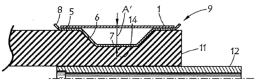
본 발명은 하부에 놓인 호스 또는 기판에 제공된 호스 클램프 조립체의 유닛 하중을 증가시키기 위해 통상적인 웜-기어 호스 클램프의 내측 직경(ID)의 접촉 표면적을 감소시키기 위한 수단을 제공한다. 접촉 표면적은 호스 클램프 또는 인장 밴드(1)의 내측 직경 내에 삽입된 원형의 라이너를 사용함으로써 감소된다. 상기 라이너의 횡단면은 호스 클램프 또는 인장 밴드의 내측 표면 폭과 축방향 수치(폭)이 거의 동일한 외측 직경(OD) 위에 접촉 표면이 있는 숄더(5)를 가진다. 숄더의 에지는 라이너를 고정하기 위한 각도에서 호스 클램프 또는 인장 밴드를 향해 상부 방향으로 돌출하여 호스 클램프 또는 인장 밴드의 내측 직경 내에 수용될 수 있다. 라이너의 프로파일은 숄더(5)보다 낮거나 내부를 향해 위치된 평평한 원통형의 접촉 부분(7)을 포함한다. 용어 "접촉"은 평평한 부분(7)이 하부에 놓인 호스 또는 기판과 닿는 것을 의미한다. 이 접촉 표면은 호스 클램프 또는 인장 밴드(1)의 폭보다 더 좁으며 호스 클램프 또는 인장 밴드 폭의 40% 내지 75% 사이 범위에 있을 수 있다. 두 레그(6)가 라이너의 하부 접촉 부분(7)과 두 숄더 사이에 연결된다(bridge). 이 레그들은 대칭으로 구성될 수 있고 하부 접촉 표면의 양쪽 면 위에 위치될 수 있으며 클램프 중앙선에 대해 예각으로 외부를 향해 돌출되어 상부 숄더에 도달하여 상부 숄더에 결부될 수 있다. The present invention provides a means for reducing the contact surface area of the inner diameter (ID) of a conventional worm-gear hose clamp to increase the unit load of the hose clamp assembly provided on the underlying hose or substrate. The contact surface area is reduced by using a circular liner inserted in the inner diameter of the hose clamp or
유닛 하중에서의 증가는 클램프가 하부에 놓인 호스 또는 기판 위에서 제공하는 반경방향 압력(radial pressure)에서의 증가로서 기술될 것이다. 호스 클램프 또는 인장 밴드가 제공하는 반경방향 압력(pr)은 밴드 인장력(T), 밴드 폭(w) 및 클램핑 직경(d)의 함수이다. 임의의 "T" 및 "d"의 고정값에 대해, "w"가 증가하면 반경방향 압력이 줄어들고, "w"이 감소하면 반경방향 압력이 증가할 것이다. 단순화된 후프 응력(hoop stress)의 조절 공식은 이러한 행태를 보여줄 수 있는데; 2T = pr w d 이고 이를 변경하면 pr = 2T/(w d)이다. An increase in the unit load will be described as an increase in radial pressure provided by the clamp on the underlying hose or substrate. The radial pressure (p r ) provided by the hose clamp or tension band is a function of the band tension (T), the band width (w) and the clamping diameter (d). For any fixed value of "T" and "d", radial pressure will decrease as "w" increases, and radial pressure will increase as "w" decreases. The simplified formula of the hoop stress can show this behavior; 2T = p r wd and changing it to p r = 2T / (wd).
호스 클램프 또는 인장 밴드의 반경방향 압력의 증가 외에도, 라이너의 접촉 폭이 더 좁아지면, 라이너는 스프링으로서 작용할 수 있으며, 이에 따라 클램프에 대해 열-상쇄 특징(thermal-compensating feature)을 제공할 수 있다. 스프링 효과는 추후에 보다 상세하게 기술될 것이다. 우선, 도면에 대해 보다 상세하게 논의될 것이다. In addition to increasing the radial pressure of the hose clamp or tension band, if the contact width of the liner becomes narrower, the liner can act as a spring, thereby providing a thermal-compensating feature for the clamp . The spring effect will be described in more detail later. First, the drawings will be discussed in more detail.
도 1을 보면, 외측 환형 밴드(1), 및 통상적인 인장 수단(3, 4)을 포함하는 호스 클램프가 도시된다. 또한, 도 1은 본 발명에 따른 평평한 스프링 라이너(9)를 분해한 도면이다. 또 다른 실시예에서, 스프링 라이너(19)의 단면이 도 2에 도시된다. 스프링 라이너(9) 및 스프링 라이너(19)는 중첩 단부(10)가 있는 환형 링이다. 스프링 라이너(9 및 19)는 라이너의 에지에 가깝게 위치된 2개의 평평한 환형 주변 숄더(5), 두 숄더(5) 사이에 위치되고 이 숄더들보다 더 작은 외주를 가진 평평한 중앙 환형 접촉 부분(7), 및 숄더(5)의 내측 에지를 평평한 접촉 부분(7)의 외측 에지에 연결하는 두 환형 주변 레그(6)를 포함한다. 도 2는 평형한 접촉 부분(7)과 두 숄더(5) 사이의 반경방향 높이차(A)를 도시한다. 라이너(9 또는 19)가 클램프 밴드(1) 내에 삽입될 때, 밴드(1)의 내측면은 숄더(5)와 접하거나 상기 숄더 위에 고정될 것이며, 클램프의 인장력이 없을 때에는 밴드(1)의 내측면과 접촉 부분(7)의 외측 표면 사이에는 틈(A)이 생길 것이다. 따라서, 평평 부분(7)은 클램프 인장력이 없을 때 밴드(1)의 내측면과 접하지 않는다. 1, there is shown a hose clamp comprising an outer
용어 "외부를 향해" 및 "내부를 향해"는 통상 원형 라이너의 중앙축에 대한 방향을 가리킨다. "내부를 향해"는 라이너의 중앙축을 향하는 방향을 의미한다. "외부를 향해"는 라이너의 중앙축으로부터 멀어지는 방향을 의미한다. The terms "outwardly" and "inwardly" refer generally to the direction about the central axis of the circular liner. "Toward the inside" means the direction toward the liner center axis. "Towards the outside" means the direction away from the center axis of the liner.
클램프 인장력을 제공할 때 즉 밴드가 조여지거나(tightening) 인장될 때, 라이너의 중첩 섹션(10)의 길이는 증가될 수 있어서 라이너의 외주가 감소된다. 밴드가 조여질 때, 라이너는 호스와 압축 결합되는(compressive engagement) 상태가 된다. 도 3은 호스(11)와 호스 피팅(12)과 함께 사용되는 호스 클램프 조립체를 예시한다. 호스 클램프의 밴드(1)는 두 숄더(5) 위에 배열된다. 라이너의 내부 방향을 향하는 평평한 접촉 부분(7)은 호스 내에 상대적으로 균일한 압축부(14) 영역을 형성한다. When providing a clamping tension, i. E. When the band is tightened and tensioned, the length of the
라이너의 프로파일은 두 레그(6)가 압축력 하에서 굴절되어(deflect) 스프링 효과를 발생시키도록 구성된다. 밴드가 인장될 때, 두 레그가 굴절되면, 틈(A)이 A'로 줄어들게 되거나(A'<A) 혹은 아마도 심지어 완전히 사라지게 될 것이다. 밴드가 인장될 때, 레그가 굴절되어 평평한 접촉 표면이 약간 변형되게 할 수 있다. 틈이 줄어드는 것은 환형의 스프링 라이너 내에 저장된 스프링 에너지의 양을 표시하는 것이다. 이러한 반경방향 및 축방향 굴절 및 이에 따라 호스에 제공되는 압축력의 전체 효과는 종래 기술의 호스 클램프 라이너 디자인으로 구현되는 효과보다 훨씬 더 우수한 초기 및 장시간의 밀봉 효과이다. The profile of the liner is configured such that the two
호스 클램프 조립체가 열변동(thermal fluctuation)에 노출될 때, 스프링 라이너는 더 많이 굴절되거나(further deflecting) 더 많이 릴렉스되는(further relaxing) 만큼 반응하여, 따라서 클램프 호스 조립체에 훌륭한 밀봉력을 유지하는 데 도움을 줄 수 있다. 시간이 지나면 탄성 특성이 저하되기 때문에, 통상 가황 고무(vulcanized rubber)인 호스 재료가 압축 변형되거나 비탄성 변형될 때, 고무에 의해 제공되는 힘은 릴렉스되거나 줄어들 것이며, 스프링 라이너는 저장된 스프링 에너지의 일부를 다시 릴렉스하거나 릴리스하여, 이에 따라 호스에 우수한 밀봉력을 유지할 것이다. 좁다란 리지(ridge)를 가져서 매우 높은 압축 영역을 생성하는 종래 기술의 라이너에 비해, 본 발명은 적당한 압축력을 가진 보다 균일한 영역을 생성하여, 클램프되는 고무 호스에서 상당하게 압축되는 효과와 상당히 변형되는 것을 방지할 수 있다. When the hose clamp assembly is exposed to thermal fluctuations, the spring liner reacts further deflecting or further relaxing to maintain a good sealing force on the clamp hose assembly You can help. Since the elastic properties are degraded over time, when the hose material, which is typically vulcanized rubber, is compression deformed or inelastically deformed, the force provided by the rubber will relax or shrink, and the spring liner will retain some of the stored spring energy Relax or release again, thus maintaining excellent hermeticity in the hose. Compared to prior art liner having a narrow ridge to create a very high compression area, the present invention produces a more uniform area with an adequate compressive force, which results in a significantly compressive effect and considerable strain in the clamped rubber hose Can be prevented.
호스 클램프가 틈(A')이 없어지고 접촉 부분(7)의 외측 표면이 밴드(1)의 내측 표면과 접촉하는 정도로 인장되는 경우, 스프링 라이너의 임의의 추가적인 굴절은 훨씬 더 많은 힘을 필요로 하며, 스프링 속도(rate)도 급격하게 증가된다. 이러한 상태 하에서, 호스의 열팽창에 반응하여 스프링 라이너가 굴절되는 것은 매우 제한된다. 하지만, 이러한 상태 하에서, 호스의 열팽창에 대해 릴랙스하거나 반응하는 스프링 라이너의 기능은 극대화된다. 따라서, 클램프 및 스프링 라이너는, 사용 시에, 심지어 클램프 인장력이 존재하는 경우에도 틈(A')이 유지되도록 구성될 수 있다. 대안으로, 클램프 및 스프링 라이너는, 사용 시에, 평평한 접촉 부분(7)의 외측 표면이 클램프 인장력이 존재할 때 호스 클램프의 내측면과 접할 수 있도록 구성될 수도 있다. If the hose clamp is tensioned to such an extent that the gap A 'is lost and the outer surface of the
도 2 및 3에 도시된 것과 같이, 스프링 라이너(19)는 라이너(19)를 밴드(1) 내에 나란하게 정렬시키는 데 도움을 주기 위해 반경 방향으로 외부를 향한 하나 또는 2개의 플레어구성된(flared) 플랜지(8)를 가질 수 있다. 도면에 도시된 플랜지는 약 45°의 각도로 외부를 향해 플레어구성된다. 임의의 적절한 플레어 각도 또는 플레어 형태가 사용될 수 있다. 플랜지(8) 및 레그(6)들은 날카롭게 굽어질 수 있거나 혹은 인접하는 숄더(5) 또는 접촉 부분(7)으로부터 점차 변이되는 보다 둥근 변이부(transition)를 가질 수도 있다. 플랜지(8)는 라이너의 전체 외주에 걸쳐 연장될 수 있거나 혹은 인장 수단(3, 4)과 라이너 사이의 줄이거나 라이너의 중첩 섹션(10) 내에서 간섭(interference)을 줄이기 위해 적당한 위치에서 짧게 절단될 수 있다(cut short). 플랜지의 대안으로 혹은 플랜지 외에도, 스프링 라이너는 적절한 결합법, 가령, 열 용접, 화학 용접, 스케이킹(staking), 기계식 파스너(mechanical fastener), 또는 이들 중 2개 이상의 조합을 제공하는 임의의 수단에 의해 밴드(1)에 거의 영구적으로 고정될 수 있는데, 상기 결합법에만 제한되는 것은 아니다. As shown in Figures 2 and 3, the
라이너에 의해 제공된 스프링 힘은 라이너를 구성하는 재료의 탄성계수(modulus)와 두께에 따른다. 이 스프링 힘은 정확한 프로파일 즉 레그, 접촉 부분, 및 숄더의 형태와 크기에 따른다. 도 2에 도시된 프로파일은, 약 0.012 인치(0.3 mm) 두께의 시트 금속으로 형성될 때, 통상적인 자동차용 호스 클램핑 분야에 적합하다. 당업자라면, 특정 적용분야에 대하여 평평한 스프링 라이너를 최적화시키기 위하여, 재료, 재료 특성, 숄더 및 평평한 표면 수치, 플랜지 각도, 중첩 거리, 및/또는 스프링 라이너 두께를 변경시킬 수도 있다. 프로파일은 반드시 완벽하게 대칭일 필요는 없다. 2개의 숄더, 레그, 및 중앙의 평평한 표면은 모두 서로 다른 크기로도 구성될 수 있다. 중앙의 평평한 표면은 환형 라이너의 정중앙에 위치될 필요가 없다. 2개의 레그 각도도 상이할 수 있다. 또한, 라이너의 두께도 축방향으로 변경될 수 있다. The spring force provided by the liner depends on the modulus and thickness of the material comprising the liner. This spring force depends on the exact profile, ie, the shape and size of the legs, the contact area, and the shoulder. The profile shown in Fig. 2 is suitable for a typical automotive hose clamping field when formed of sheet metal of about 0.012 inch (0.3 mm) thickness. Those skilled in the art will also be able to vary material, material properties, shoulder and flat surface values, flange angle, overlap distance, and / or spring liner thickness to optimize a flat spring liner for a particular application. The profile need not be perfectly symmetrical. The two shoulders, the legs, and the central flat surface can all be of different sizes. The central flat surface need not be located in the center of the annular liner. The two leg angles can also be different. Further, the thickness of the liner can also be changed in the axial direction.
숄더는 반드시 넓고 평평하게 구성될 필요가 없다. 숄더 또는 숄더들이 호스 클램프의 밴드의 내측면과 접하도록 구성된 주변 접촉선(circumferential line of contact)일 수 있다. 이러한 숄더는 라이너의 에지 근처에 형성된 외부를 향해 볼록한 리지일 수 있거나, 혹은, 단순히 라이너의 에지일 수도 있다. 숄더의 중요하는 특징은 호스 클램프의 밴드의 내측면과 접촉하거나 접하도록 구성된다는 점이다. 도 3에서와 같이 단면으로 도시되었을 때, 숄더(5)와 밴드(1)의 내측면 사이의 접촉은 점접촉이거나 선접촉일 수 있다. 따라서, 3차원 관점에서 보면, 숄더(5)와 밴드(1)의 내측면 사이의 접촉은 숄더의 형태에 따라 원형의 선 또는 원통형의 면접촉일 수 있다. The shoulder does not necessarily have to be wide and flat. The shoulders or shoulders may be circumferential line of contact configured to contact the inner surface of the band of the hose clamp. Such a shoulder may be a convex ridge towards the outside formed near the edge of the liner, or may simply be the edge of the liner. An important feature of the shoulder is that it is configured to contact or contact the inner surface of the band of the hose clamp. 3, the contact between the
스프링 라이너의 중첩 단부들 사이의 마찰은 조립 동안 발생하는 클램핑 힘(clamping force)에 영향을 끼칠 수 있다. 마찰력을 줄이기 위하여, 중첩 단부들은 왁스 또는 그 외의 다른 적합한 윤활제로 코팅될 수 있다. 마찰력을 증가시키기 위하여, 중첩 섹션은 깨끗하게 되거나(cleaned), 거칠게 만들거나(roughened), 홈을 형성하거나(grooved), 널링처리(knurled) 등을 할 수 있다. 따라서, 당업자는 필요 시에 혹은 원할 때 마찰력을 최적화시킬 수 있다. Friction between overlapping ends of the spring liner can affect the clamping force that occurs during assembly. To reduce frictional forces, the overlapping ends may be coated with wax or other suitable lubricant. To increase frictional forces, the overlapping sections may be cleaned, roughened, grooved, knurled, and the like. Thus, one skilled in the art can optimize the frictional force when needed or desired.
종래 기술에 알려져 있는 다양한 호스 클램프 조임 또는 인장 수단 즉 "텐셔너(tensioner)" 중 임의의 수단이 사용될 수 있다. 한 예로서, 인장 메커니즘은 도 1에 도시된 것과 같이 웜 드라이브(3, 4)일 수도 있다. 대안으로, 텐셔너는 T-볼트, 래칫 메커니즘(ratcheting mechanism), 볼트-배럴 메커니즘, 너트-볼트 조립체, 영구 크림프(permanent crimp) 등, 또는 이들의 조합일 수 있다. 대안으로, 클램프는 열적으로 냉각 변형되는(thermally frozen-in strain) 무한 밴드(endless band)일 수 있으며, 변형율(strain)을 릴리스함으로써 인장되고 밴드가 스프링 라이너, 호스 및 피팅에 압축될(shrink) 수 있게 한다. 또한, 인장 밴드 또는 호스 클램프 폭은 변경될 수 있다. 인장 밴드 폭 대 라이너 폭 및 라이너 접촉 폭의 비율은 변경될 수 있다. Any of a variety of hose clamp tightening or tensioning means or "tensioners" known in the art may be used. As an example, the tensioning mechanism may be a
호스 클램프의 그 밖의 알려져 있는 특징들은 원할 시에 본 발명의 범위를 벗어나지 않고도 본 발명에서 활용될 수 있다. 예를 들어, 조립체를 호스에 결부시키기 위한 다양한 수단, 가령, 접착제, 가화 패치, 배열 탭, 배열 클립 등도 활용될 수 있다. 스프링 강도를 조절하기 위한 절단부(cutout) 또는 구멍 등도 활용될 수 있다. Other known features of the hose clamp can be utilized in the present invention without departing from the scope of the present invention when desired. For example, various means for attaching the assembly to the hose, such as an adhesive, a patch, an array tab, an array clip, and the like, may also be utilized. A cutout or hole for adjusting the spring strength may also be utilized.
실제 실시예에서, 환형 스프링 라이너를 가진 호스 클램프가 결합되어야 하는 호스 및 피팅 위에 위치된다. 클램프 직경은 인장 메커니즘에 의해 줄어든다. 스프링 라이너 직경은 라이너의 주변 중첩 길이를 증가시킴으로써 클램프 직경이 줄어드는 데 비례하여 줄어든다. 조합된 호스 클램프와 환형 스프링 라이너 직경이 줄어듬에 따라, 하부에 배열된 호스 및 피팅에 작용하는 반경방향 압력이 증가한다. 라이너의 형태로 인해, 호스에 작용하는 반경방향 압력은, 라이너 밑의 호스 영역에서는 상대적으로 일정하게 유지되는 반면, 클램프 단독에 의해 생성되는 형태로부터 증폭된다(amplified). In an actual embodiment, a hose clamp with an annular spring liner is placed over the hose and fitting to which it is to be coupled. The clamp diameter is reduced by the tension mechanism. The spring liner diameter decreases proportionally as the clamp diameter decreases by increasing the peripheral overlap length of the liner. As the combined hose clamp and annular spring liner diameters decrease, the radial pressure acting on the hoses and fittings arranged below is increased. Due to the shape of the liner, the radial pressure acting on the hose is amplified from the shape produced by the clamp alone while it remains relatively constant in the hose area under the liner.
외부 밴드에 인장력이 증가함으로써 스프링 라이너에 작용하는 반경방향 힘들이 증가하게 되면, 스프링 라이너는 숄더(5)가 호스(11)를 향해 하부 방향으로 굴절되도록 굴절된다. 이러한 움직임(movement)은 원하는 인장력이 구현될 때까지 지속될 수 있다. 하지만, 상기 움직임은 중앙의 평평한 부분(7)이 클램프 밴드(1)의 내측면과 접촉하는(만약 접촉한다면) 지점에서는 제한된다. 굴절(deflection)은 탄성의 스프링 형태의 행태이다. 따라서, 라이너는 스프링으로서 반경방향 압력 및/또는 밴드 인장력에서의 변동(variation)에 반응할 수 있다. 이러한 스프링 행태로 인해, 설치된 클램프의 전체 수명에 걸쳐 중앙의 평평한 부분(7)이 호스에 충분한 반경방향 압력을 제공할 수 있게 된다. As the radial forces acting on the spring liner increase due to the increased tension on the outer band, the spring liner is deflected such that the
가능한 한 변형예의 예로서, 본 발명의 한 실시예에서, 조립될 때, 호스 클램프의 내측면은 초기에 스프링 라이너의 한 숄더와 접촉될 수 있으며, 클램프의 내측면과 라이너의 제 2 숄더 사이에 틈(gap)이 존재한다. 상기 실시예의 호스 클램프가 인장될 때, 제 2 숄더와 내측면 사이의 틈은 변형 에너지가 스프링 라이너 내에 저장됨에 따라 닫힐 것이며, 클램프는 최종적으로 아마도 제 2 숄더 위에 위치될 것이다. As an example of a modification, in one embodiment of the present invention, when assembled, the inner surface of the hose clamp may initially be in contact with one shoulder of the spring liner, and between the inner surface of the clamp and the second shoulder of the liner There is a gap. When the hose clamp of the embodiment is tensioned, the gap between the second shoulder and the inner surface will be closed as the strain energy is stored in the spring liner, and the clamp will eventually be positioned above the second shoulder.
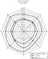
하기 예는 본 발명의 한 실시예의 이점과 사용 방법을 예시한다. 이 예에서, 도 1에 도시된 것과 같이 웜 드라이브가 인장된 호스 클램프를 구현하였다. 밴드는 0.405 인치(10.3 mm)의 폭과 약 2.5 인치(약 65 mm)의 공칭 직경을 가진다. 본 발명의 한 예로서, 도 2에 도시된 것과 같이, 0.165 인치(4.2 mm)의 접촉 부분(7)의 폭과 0.47 인치(11.9 mm)의 전체 폭을 가진 스프링 라이너가 구성되어, 위에서 언급한 호스 클램프와 함께 사용된다. 비교예 1로서, 스프링 라이너가 없는 호스 클램프를 사용하였다. 비교예 2로서, 미국 특허번호 7,302,741호에 따라 2개의 내부를 향하는 리지를 가지며 호스 클램프와 함께 사용하고 앞에서와 비슷한 전체 폭을 가진 스프링 라이너를 구성하였다. The following examples illustrate the advantages of one embodiment of the invention and how to use it. In this example, the worm drive implemented a tensioned hose clamp as shown in Fig. The band has a width of 0.405 inches (10.3 mm) and a nominal diameter of about 2.5 inches (about 65 mm). As an example of the present invention, a spring liner having a width of 0.165 inch (4.2 mm) of the
부드러운 원통형의 맨드릴(mandrel) 또는 피팅이 삽입된 약 2.25-인치의 내측 직경을 가진 강화 고무 호스(reinforced rubber hose)에 3개의 실시예를 차례로 적용하였다. 맨드릴과 호스 사이에, 필름(film) 타입의 압력 센서를 삽입하였다. 맨드릴과 호스 사이의 압력 프로파일은 주변 방향으로 약 31개 위치 및 축방향으로 44개 위치에서 기록하였으며, 라이너 바로 밑에 배치된 위치들에 대한 평균 압력을 계산하여 정규 기준(normalized basis)에 따라 비교하였다. 본 발명의 실시예와 비교예 1 및 2에 대해서, 30 인치-파운드(3.4 N-m)의 똑같은 토크를 웜 드라이브에 제공하였다. 이 비교 결과가 표 1에 나타난다. 상기 비교에 대한 곡선의 압력 프로파일이 도 4에 도시된다. 비교 실시예들은 도 4에 "비교예 1" 및 "비교예 2"로 표시된다. 각각의 31개의 주변 위치들에서 축방향을 따라 모든 위치들의 평균을 계산함으로써(averaging), 도 4의 프로파일이 부드럽게 형성되었다. 그 다음에, 주변 데이터의 3개의 연속 데이터 지점의 한 그룹과 4개의 7 그룹의 평균을 계산하여, 도 4에 도시된 곡선 주변 압력 프로파일을 위한 8개의 데이터 지점을 얻었다. Three examples were applied in turn to a reinforced rubber hose having an inner diameter of about 2.25-inches, into which a soft cylindrical mandrel or fitting was inserted. A film type pressure sensor was inserted between the mandrel and the hose. The pressure profile between the mandrel and the hose was recorded at about 31 positions in the circumferential direction and at 44 positions in the axial direction and was compared according to a normalized basis by calculating the average pressure for the positions disposed directly beneath the liner . For the Examples of this invention and Comparative Examples 1 and 2, the same torque of 30 inch-pounds (3.4 N-m) was provided to the worm drive. The results of this comparison are shown in Table 1. The pressure profile of the curve for the comparison is shown in FIG. Comparative Examples are shown in FIG. 4 as "Comparative Example 1" and "Comparative Example 2". The profile of FIG. 4 was smoothly formed by averaging all positions along the axial direction at each of the 31 peripheral positions. Then, the average of one group of three consecutive data points and four groups of seven of the surrounding data was calculated to obtain eight data points for the curve pressure profile shown in FIG.
(라이너 없음)Comparative Example 1
(No liner)
(종래의 라이너)Comparative Example 2
(Conventional liner)
표 1과 도 4에 도시된 결과는 본 발명의 스프링 라이너의 여러 이점들을 예시한다. 표 1에 도시된 평균 압력 결과들은 반경방향의 밀봉 압력을 증가시키기 위해 스프링 라이너가 어떻게 클램프 힘을 증폭시킬 수 있는 지를 예시한다. 라이너가 없는 클램프에 대해 평균 압력이 42% 증가했지만, 밴드와 비교하여 본 발명의 라이너의 폭 차이로부터 예측한 값보다는 작다. 이렇게 약간 작은 것은, 고무 내의 완화(relaxation) 또는 압축 및 에지 효과(edge effect) 때문인 것으로 믿어진다. 이에 따라, 특정 이점들은 클램프 고정된 재료와 호스 구성의 상세한 내용에 따른다. 따라서, 본 발명의 이점 및 종래 기술의 라이너에 비해 상대적인 이점들은 적용 타입과 호스의 유형에 좌우될 수 있다. 2개의 리지가 있는 종래 기술의 라이너는 리지 바로 밑에서 더 높은 압력을 제공할 수 있다. 하지만, 어떤 타입의 호스는 낮은 피크 압력이 아니라 더 높은 평균 압력으로 훨씬 더 우수하게 클램프 고정될 수 있다. 도 4에서, 본 발명의 실시예에 대한 클램프 압력은 전체 주변에 대해서 비교예들보다 더 높다. 이는 본 발명의 실시예에 대한 밀봉 성능이 개선되었다고 해석되어야 한다. 또한, 도 4는 라이너가 없는 비교예보다 상기 평평한 스프링 라이너가 클램프 주변에서 보다 균일한 압력 분포를 제공하는 것을 예시한다. 웜 드라이브 영역(도 4에서 5번 위치 가까이)에서의 변동(variation)은 라이너가 없을 때보다 라이너가 사용될 때 현저하게 더 적다. 이 또한 밀봉 성능이 개선되었다고 해석되어야 한다. The results shown in Table 1 and Figure 4 illustrate several advantages of the spring liner of the present invention. The average pressure results shown in Table 1 illustrate how the spring liner can amplify the clamping force to increase the radial sealing pressure. The average pressure increased 42% for the linerless clamp, but less than the value predicted from the width difference of the liner of the present invention as compared to the band. It is believed that this slightly smaller size is due to the relaxation or compression in the rubber and the edge effect. Accordingly, certain advantages depend on the details of the clamped material and hose configuration. Thus, the advantages of the present invention and the advantages relative to prior art liners can depend on the type of application and the type of hose. The prior art liner with two ridges can provide a higher pressure just below the ridge. However, any type of hose can be clamped much better with a higher average pressure, rather than a lower peak pressure. 4, the clamp pressure for the embodiment of the present invention is higher than the comparative example for the entire periphery. It should be understood that the sealing performance for the embodiment of the present invention is improved. Figure 4 also illustrates that the flat spring liner provides a more uniform pressure distribution around the clamp than the comparative example without a liner. The variation in the warm drive area (near
본 발명과 본 발명의 이점들이 상세하게 기술되었지만, 하기 기술된 청구범위에서 정의된 것과 같이 본 발명의 사상과 범위를 벗어나지 않고도 본 명세서에서 여러 변형예, 대체예, 및 대안예들도 가능하다는 사실을 이해해야 한다. 게다가, 본 발명의 범위는 본 명세서에 기술된 특정 실시예들의 공정, 기계, 제작법, 재료 조성, 수단, 방법, 및 단계들에만 제한하려는 것이 아니다. 당업자가 본 발명의 기술 내용으로부터 쉽게 이해할 수 있는 것과 같이, 본 발명의 기술내용, 공정, 기계, 제작법, 재료 조성, 수단, 방법, 및 단계들은, 본 명세서에서 기술된 상응하는 실시예들이 본 발명에 따라 사용될 수 있기 때문에, 실질적으로 똑같은 기능을 수행하거나 실질적으로 똑같은 결과를 구현할 수 있도록 기존에 존재하거나 추후에 개발되어야 한다. 이에 따라, 하기 청구범위는 본 발명의 기술내용, 공정, 기계, 제작법, 재료 조성, 수단, 방법, 또는 단계들을 본 발명의 범위 내에 포함하기 위한 것이다. 본 명세서에 기술된 발명은 본 명세서에 명시적으로 기술되지 않은 임의의 요소가 없을 때에도 적절하게 실시될 수 있을 것이다. Although the present invention and its advantages have been described in detail, it should be understood that various changes, substitutions, and alternatives are possible herein without departing from the spirit and scope of the invention as defined in the following claims . Furthermore, the scope of the present invention is not intended to be limited solely to the process, machine, fabrication, material composition, means, methods and steps of the specific embodiments described herein. It will be understood by those skilled in the art that the technical content, processes, machines, fabrication methods, material compositions, means, methods, and steps of the present invention, as well as the corresponding embodiments described herein, It must be existing or later developed so as to perform substantially the same function or to achieve substantially the same result. Accordingly, the following claims are intended to cover within the scope of this invention the technical content, processes, machines, fabrication methods, material compositions, means, methods, or steps of the present invention. The invention described herein may be suitably practiced in the absence of any element not expressly set forth herein.
Claims (6)
스프링 라이너를 제공하는 단계 - 상기 스프링 라이너는 스프링 라이너의 제1 에지 근처의 제1 주변 숄더, 스프링 라이너의 제2 에지 근처의 제2 주변 숄더, 스프링 라이너의 횡단면을 볼 때 스프링 라이너의 제1 및 제2 숄더보다 더 작은 외주를 갖는 평평한 표면 섹션을 포함한 중앙의 접촉 부분, 제1 주변 숄더에 상기 중앙의 접촉 부분을 연결하는 내측을 향하여 연장되는 제1 레그, 및 제2 주변 숄더에 중앙의 접촉 부분을 연결하는 내측을 향하여 연장되는 제2 레그를 포함함 - ,
상기 중앙의 접촉 부분이 밴드의 내측면으로부터 이격되도록 스프링 라이너의 제1 및 제2 주변 숄더를 밴드의 내측면과 결합시키는 단계,
상기 밴드 및 스프링 라이너를 호스 위에 배열하는 단계,
스프링 라이너의 중앙의 접촉 부분이 호스와 결합되도록 밴드를 조이는 단계(tightening), 및
호스의 주변 주위에 균일한 압축부의 영역을 형성하고, 스프링 라이너의 중앙의 접촉 부분의 평평한 표면 섹션과 밴드의 내측면 사이에 형성된 간격을 탄성적으로 감소시키기 위해 스프링 라이너를 굴절시키는 단계(deflecting)를 포함하는 클램프를 설치하기 위한 방법.CLAIMS 1. A method for installing a clamp,
Providing a spring liner, the spring liner having a first peripheral shoulder near the first edge of the spring liner, a second peripheral shoulder near the second edge of the spring liner, a first peripheral shoulder near the first edge of the spring liner, A central contact portion including a flat surface section having a smaller outer circumference than the second shoulder, a first leg extending toward the inside connecting the central contact portion to the first peripheral shoulder, and a central contact And a second leg extending toward the inside connecting the portions,
Engaging the first and second peripheral shoulders of the spring liner with the inner surface of the band such that the central contact portion is spaced from the inner side of the band,
Arranging the band and spring liner on the hose,
Tightening the band so that the central contact portion of the spring liner is engaged with the hose, and
Deflecting the spring liner to form an area of the uniform compression around the periphery of the hose and resiliently reducing the spacing formed between the flat surface section of the central contact portion of the spring liner and the inner surface of the band, Gt; a < / RTI > clamp.
밴드의 내측면과 제1 주변 숄더의 제1 원통형 표면을 결합하는 단계, 및
밴드의 내측면과 제2 주변 숄더의 제2 원통형 표면을 결합하는 단계를 포함하는 클램프를 설치하기 위한 방법.2. The method of claim 1 wherein engaging the inner side of the band with the first and second peripheral shoulders of the spring liner
Coupling the inner surface of the band with the first cylindrical surface of the first peripheral shoulder, and
And engaging the inner surface of the band with the second cylindrical surface of the second peripheral shoulder.
밴드의 내측면과 스프링 라이너의 제1 및 제2 주변 숄더를 결합하는 단계는 제1 플랜지와 제2 플랜지 사이에 밴드를 배열하는 단계를 포함하는 클램프를 설치하기 위한 방법.The spring liner of claim 1 wherein the spring liner comprises a second flange extending from an end attached to the second peripheral shoulder at a second edge of the spring liner and a second flange extending from an end attached to the first peripheral shoulder at a first edge of the spring liner 1 < / RTI > flange,
Wherein engaging the inner side of the band with the first and second peripheral shoulders of the spring liner comprises arranging the band between the first flange and the second flange.
Applications Claiming Priority (3)
| Application Number | Priority Date | Filing Date | Title |
|---|---|---|---|
| US13/188,093 US8650719B2 (en) | 2011-07-21 | 2011-07-21 | Hose clamp with flat spring liner |
| US13/188,093 | 2011-07-21 | ||
| PCT/US2012/047597 WO2013013149A1 (en) | 2011-07-21 | 2012-07-20 | Hose clamp with flat spring liner |
Related Parent Applications (1)
| Application Number | Title | Priority Date | Filing Date |
|---|---|---|---|
| KR1020147004482A Division KR20140057279A (en) | 2011-07-21 | 2012-07-20 | Hose clamp with flat spring liner |
Publications (1)
| Publication Number | Publication Date |
|---|---|
| KR20180077328A true KR20180077328A (en) | 2018-07-06 |
Family
ID=47554708
Family Applications (2)
| Application Number | Title | Priority Date | Filing Date |
|---|---|---|---|
| KR1020147004482A KR20140057279A (en) | 2011-07-21 | 2012-07-20 | Hose clamp with flat spring liner |
| KR1020187018510A KR20180077328A (en) | 2011-07-21 | 2012-07-20 | Hose clamp with flat spring liner |
Family Applications Before (1)
| Application Number | Title | Priority Date | Filing Date |
|---|---|---|---|
| KR1020147004482A KR20140057279A (en) | 2011-07-21 | 2012-07-20 | Hose clamp with flat spring liner |
Country Status (9)
| Country | Link |
|---|---|
| US (5) | US8650719B2 (en) |
| EP (2) | EP3650738B1 (en) |
| JP (2) | JP6117201B2 (en) |
| KR (2) | KR20140057279A (en) |
| CN (4) | CN203549132U (en) |
| CA (1) | CA2842512C (en) |
| ES (2) | ES2930071T3 (en) |
| RU (1) | RU2599695C2 (en) |
| WO (1) | WO2013013149A1 (en) |
Families Citing this family (10)
| Publication number | Priority date | Publication date | Assignee | Title |
|---|---|---|---|---|
| US8650719B2 (en) | 2011-07-21 | 2014-02-18 | Ideal Clamp Products, Inc. | Hose clamp with flat spring liner |
| CN104482344A (en) * | 2014-10-29 | 2015-04-01 | 张明 | Hose clamp with ripple spring inner lining |
| CN105465520A (en) * | 2015-12-08 | 2016-04-06 | 天津市凯诺实业有限公司 | High-repeated-use hose clamp |
| US10584817B2 (en) | 2015-12-28 | 2020-03-10 | Ideal Clamp Products, Inc. | Hose clamp with retaining bracket |
| US20180340557A1 (en) * | 2017-05-26 | 2018-11-29 | Ideal Clamp Products, Inc. | Hose clamp with indicator |
| US10495244B2 (en) | 2017-08-20 | 2019-12-03 | Mann+Hummel Gmbh | Positionally fixed clamp and a hose or duct having a positionally fixed clamp |
| CN107420654A (en) * | 2017-10-10 | 2017-12-01 | 季永东 | Flexible pipe and grip device, clamp member and method |
| WO2019099640A1 (en) * | 2017-11-15 | 2019-05-23 | Ideal Clamp Products, Inc. | Hose clamp with spring liner and method |
| DE112019007861A5 (en) | 2019-10-30 | 2022-08-11 | Oetiker Schweiz Ag | Clamp with indentations in an insert |
| CN112096990B (en) * | 2020-09-30 | 2022-06-14 | 南京润驰橡胶制品有限公司 | Disconnect-type high pressure hydraulic hose connector |
Family Cites Families (24)
| Publication number | Priority date | Publication date | Assignee | Title |
|---|---|---|---|---|
| US2089940A (en) | 1935-07-17 | 1937-08-17 | Du Pont | Coupling device for collapsible tubes |
| US3142881A (en) | 1962-06-06 | 1964-08-04 | Alva J Johnston | Hose clamp |
| CH405027A (en) | 1963-01-29 | 1965-12-31 | Oetiker Hans | Hose clamp |
| US3233922A (en) * | 1963-07-29 | 1966-02-08 | Cast Iron Soil Pipe Inst | Pipe joint |
| US4312101A (en) | 1978-09-26 | 1982-01-26 | Hans Oetiker | Hose clamp with insert member |
| US4310956A (en) | 1979-02-05 | 1982-01-19 | Meckstroth Alan F | Hose clamp with tangential screw |
| US4308648A (en) | 1980-03-31 | 1982-01-05 | Murray Corporation | Convoluted hose clamps |
| SE445065B (en) | 1983-12-23 | 1986-05-26 | Allmaenna Brandredskapsaffaere | SLANGKLEMMA |
| USD285171S (en) | 1984-07-26 | 1986-08-19 | Western Filament, Inc. | Clamp sleeve |
| US5195788A (en) | 1990-01-30 | 1993-03-23 | Hans Oetiker | Insert member for use with hose clamp arrangements |
| DE4005631A1 (en) | 1990-02-22 | 1991-09-05 | Rasmussen Gmbh | HOSE CLAMP |
| US5220710A (en) | 1991-08-15 | 1993-06-22 | Ta Mfg. Co. | Cable clamp |
| JPH0726712B2 (en) | 1991-08-16 | 1995-03-29 | ラスムッセン ジイエムビイエイチ | Hose clip |
| SE500904C2 (en) | 1993-09-15 | 1994-09-26 | Aba Sweden Ab | Device for hose clamps |
| CN2234031Y (en) | 1995-10-06 | 1996-08-28 | 金惠民 | Guard staple type pipe coupling |
| GB2326920A (en) | 1997-07-01 | 1999-01-06 | Rasmussen Gmbh | Clamp for clamping a hose on a pipe portion |
| DE19806235A1 (en) | 1998-02-16 | 1999-09-09 | Rasmussen Gmbh | Clamp arrangement |
| DE10061425A1 (en) * | 2000-12-09 | 2002-06-13 | Bayerische Motoren Werke Ag | System for attaching elastomeric hose to connector comprises press-fitting or clamp and locking component nearer end of hose which presses hose radially against connector, even at temperatures below freezing point of elastomer |
| US6877191B2 (en) | 2001-09-17 | 2005-04-12 | Dwws, Llc | Band clamp |
| US7178204B2 (en) * | 2005-01-27 | 2007-02-20 | Epicor Industries, Inc. | Hose clamp and spring liner |
| US7389568B2 (en) | 2005-07-27 | 2008-06-24 | Epicor Industries, Inc. | Compression hose clamp |
| DE102006048336B4 (en) * | 2006-10-12 | 2013-07-04 | Norma Germany Gmbh | hose clamp |
| DE202007019445U1 (en) | 2007-11-09 | 2012-08-09 | Progeral Indústria de Artefatos Plásticos Ltda. | hose clamp |
| US8650719B2 (en) | 2011-07-21 | 2014-02-18 | Ideal Clamp Products, Inc. | Hose clamp with flat spring liner |
-
2011
- 2011-07-21 US US13/188,093 patent/US8650719B2/en active Active
-
2012
- 2012-07-20 JP JP2014521823A patent/JP6117201B2/en active Active
- 2012-07-20 RU RU2014106428/06A patent/RU2599695C2/en active
- 2012-07-20 CN CN201320337213.4U patent/CN203549132U/en not_active Expired - Fee Related
- 2012-07-20 KR KR1020147004482A patent/KR20140057279A/en active Search and Examination
- 2012-07-20 KR KR1020187018510A patent/KR20180077328A/en active Search and Examination
- 2012-07-20 EP EP19197195.1A patent/EP3650738B1/en active Active
- 2012-07-20 CA CA2842512A patent/CA2842512C/en active Active
- 2012-07-20 CN CN201220356117XU patent/CN203068013U/en not_active Expired - Fee Related
- 2012-07-20 ES ES19197195T patent/ES2930071T3/en active Active
- 2012-07-20 CN CN201710013027.8A patent/CN106907540B/en active Active
- 2012-07-20 EP EP12814366.6A patent/EP2734766B1/en active Active
- 2012-07-20 CN CN201280045766.0A patent/CN103827566B/en active Active
- 2012-07-20 WO PCT/US2012/047597 patent/WO2013013149A1/en active Application Filing
- 2012-07-20 ES ES12814366T patent/ES2753182T3/en active Active
-
2014
- 2014-02-17 US US14/181,892 patent/US9447903B2/en active Active
-
2016
- 2016-09-20 US US15/270,140 patent/US10036501B2/en active Active
-
2017
- 2017-03-21 JP JP2017054794A patent/JP6800791B2/en active Active
-
2018
- 2018-07-30 US US16/049,051 patent/US10527211B2/en active Active
-
2020
- 2020-01-07 US US16/736,556 patent/US10969044B2/en active Active
Also Published As
| Publication number | Publication date |
|---|---|
| CA2842512C (en) | 2020-01-07 |
| ES2930071T3 (en) | 2022-12-05 |
| EP2734766A1 (en) | 2014-05-28 |
| JP2014526020A (en) | 2014-10-02 |
| US20130019440A1 (en) | 2013-01-24 |
| US10527211B2 (en) | 2020-01-07 |
| CN103827566A (en) | 2014-05-28 |
| US20180335171A1 (en) | 2018-11-22 |
| EP2734766A4 (en) | 2015-03-18 |
| US20170167651A1 (en) | 2017-06-15 |
| EP2734766B1 (en) | 2019-09-18 |
| WO2013013149A1 (en) | 2013-01-24 |
| US8650719B2 (en) | 2014-02-18 |
| CN106907540A (en) | 2017-06-30 |
| JP2017150664A (en) | 2017-08-31 |
| JP6117201B2 (en) | 2017-04-19 |
| CN103827566B (en) | 2017-02-08 |
| JP6800791B2 (en) | 2020-12-16 |
| CN203068013U (en) | 2013-07-17 |
| EP3650738A1 (en) | 2020-05-13 |
| CA2842512A1 (en) | 2013-01-24 |
| US10969044B2 (en) | 2021-04-06 |
| US20200141527A1 (en) | 2020-05-07 |
| US20140310922A1 (en) | 2014-10-23 |
| CN106907540B (en) | 2019-01-22 |
| KR20140057279A (en) | 2014-05-12 |
| RU2599695C2 (en) | 2016-10-10 |
| EP3650738B1 (en) | 2022-09-21 |
| US9447903B2 (en) | 2016-09-20 |
| RU2014106428A (en) | 2015-08-27 |
| ES2753182T3 (en) | 2020-04-07 |
| CN203549132U (en) | 2014-04-16 |
| US10036501B2 (en) | 2018-07-31 |
Similar Documents
| Publication | Publication Date | Title |
|---|---|---|
| US10969044B2 (en) | Clamp assemblies and methods | |
| JP6076976B2 (en) | Hose clamp with corrugated spring liner | |
| JP4714748B2 (en) | Hose clamp and spring liner | |
| WO2018010821A1 (en) | V-clamp for coupling flanged pipes | |
| KR20190087612A (en) | Profiled clamp | |
| CN108290669B (en) | Hose clamp |
Legal Events
| Date | Code | Title | Description |
|---|---|---|---|
| A107 | Divisional application of patent | ||
| A201 | Request for examination | ||
| E902 | Notification of reason for refusal | ||
| AMND | Amendment | ||
| E601 | Decision to refuse application | ||
| AMND | Amendment | ||
| J201 | Request for trial against refusal decision | ||
| J301 | Trial decision |
Free format text: TRIAL NUMBER: 2019101002718; TRIAL DECISION FOR APPEAL AGAINST DECISION TO DECLINE REFUSAL REQUESTED 20190814 Effective date: 20200731 |