EP2734766B1 - Hose clamp with flat spring liner - Google Patents
Hose clamp with flat spring liner Download PDFInfo
- Publication number
- EP2734766B1 EP2734766B1 EP12814366.6A EP12814366A EP2734766B1 EP 2734766 B1 EP2734766 B1 EP 2734766B1 EP 12814366 A EP12814366 A EP 12814366A EP 2734766 B1 EP2734766 B1 EP 2734766B1
- Authority
- EP
- European Patent Office
- Prior art keywords
- liner
- hose
- clamp
- hose clamp
- band
- Prior art date
- Legal status (The legal status is an assumption and is not a legal conclusion. Google has not performed a legal analysis and makes no representation as to the accuracy of the status listed.)
- Active
Links
- 239000000758 substrate Substances 0.000 claims description 4
- 230000000052 comparative effect Effects 0.000 description 10
- 230000006835 compression Effects 0.000 description 10
- 238000007906 compression Methods 0.000 description 10
- 230000008901 benefit Effects 0.000 description 8
- 230000007423 decrease Effects 0.000 description 7
- 230000000694 effects Effects 0.000 description 7
- 239000000463 material Substances 0.000 description 6
- 238000007789 sealing Methods 0.000 description 6
- 230000007246 mechanism Effects 0.000 description 4
- 238000000034 method Methods 0.000 description 3
- 230000009467 reduction Effects 0.000 description 3
- 230000008602 contraction Effects 0.000 description 2
- 230000006866 deterioration Effects 0.000 description 2
- 239000012530 fluid Substances 0.000 description 2
- 239000000126 substance Substances 0.000 description 2
- 238000003466 welding Methods 0.000 description 2
- 238000012935 Averaging Methods 0.000 description 1
- 230000001154 acute effect Effects 0.000 description 1
- 239000000853 adhesive Substances 0.000 description 1
- 230000001070 adhesive effect Effects 0.000 description 1
- 230000000712 assembly Effects 0.000 description 1
- 238000000429 assembly Methods 0.000 description 1
- 238000010276 construction Methods 0.000 description 1
- 230000001419 dependent effect Effects 0.000 description 1
- 238000009434 installation Methods 0.000 description 1
- 230000007774 longterm Effects 0.000 description 1
- 239000000314 lubricant Substances 0.000 description 1
- 238000004519 manufacturing process Methods 0.000 description 1
- 239000002184 metal Substances 0.000 description 1
- 239000000203 mixture Substances 0.000 description 1
- 230000004048 modification Effects 0.000 description 1
- 238000012986 modification Methods 0.000 description 1
- 230000008520 organization Effects 0.000 description 1
- 239000004033 plastic Substances 0.000 description 1
- 230000008569 process Effects 0.000 description 1
- 230000002040 relaxant effect Effects 0.000 description 1
- 230000004044 response Effects 0.000 description 1
- 230000007704 transition Effects 0.000 description 1
- 238000009827 uniform distribution Methods 0.000 description 1
- 239000004636 vulcanized rubber Substances 0.000 description 1
Images

Classifications
-
- F—MECHANICAL ENGINEERING; LIGHTING; HEATING; WEAPONS; BLASTING
- F16—ENGINEERING ELEMENTS AND UNITS; GENERAL MEASURES FOR PRODUCING AND MAINTAINING EFFECTIVE FUNCTIONING OF MACHINES OR INSTALLATIONS; THERMAL INSULATION IN GENERAL
- F16L—PIPES; JOINTS OR FITTINGS FOR PIPES; SUPPORTS FOR PIPES, CABLES OR PROTECTIVE TUBING; MEANS FOR THERMAL INSULATION IN GENERAL
- F16L33/00—Arrangements for connecting hoses to rigid members; Rigid hose connectors, i.e. single members engaging both hoses
- F16L33/02—Hose-clips
- F16L33/08—Hose-clips in which a worm coacts with a part of the hose-encircling member that is toothed like a worm-wheel
-
- F—MECHANICAL ENGINEERING; LIGHTING; HEATING; WEAPONS; BLASTING
- F16—ENGINEERING ELEMENTS AND UNITS; GENERAL MEASURES FOR PRODUCING AND MAINTAINING EFFECTIVE FUNCTIONING OF MACHINES OR INSTALLATIONS; THERMAL INSULATION IN GENERAL
- F16B—DEVICES FOR FASTENING OR SECURING CONSTRUCTIONAL ELEMENTS OR MACHINE PARTS TOGETHER, e.g. NAILS, BOLTS, CIRCLIPS, CLAMPS, CLIPS OR WEDGES; JOINTS OR JOINTING
- F16B2/00—Friction-grip releasable fastenings
- F16B2/02—Clamps, i.e. with gripping action effected by positive means other than the inherent resistance to deformation of the material of the fastening
- F16B2/06—Clamps, i.e. with gripping action effected by positive means other than the inherent resistance to deformation of the material of the fastening external, i.e. with contracting action
- F16B2/065—Clamps, i.e. with gripping action effected by positive means other than the inherent resistance to deformation of the material of the fastening external, i.e. with contracting action using screw-thread elements
-
- F—MECHANICAL ENGINEERING; LIGHTING; HEATING; WEAPONS; BLASTING
- F16—ENGINEERING ELEMENTS AND UNITS; GENERAL MEASURES FOR PRODUCING AND MAINTAINING EFFECTIVE FUNCTIONING OF MACHINES OR INSTALLATIONS; THERMAL INSULATION IN GENERAL
- F16B—DEVICES FOR FASTENING OR SECURING CONSTRUCTIONAL ELEMENTS OR MACHINE PARTS TOGETHER, e.g. NAILS, BOLTS, CIRCLIPS, CLAMPS, CLIPS OR WEDGES; JOINTS OR JOINTING
- F16B2/00—Friction-grip releasable fastenings
- F16B2/02—Clamps, i.e. with gripping action effected by positive means other than the inherent resistance to deformation of the material of the fastening
- F16B2/06—Clamps, i.e. with gripping action effected by positive means other than the inherent resistance to deformation of the material of the fastening external, i.e. with contracting action
- F16B2/08—Clamps, i.e. with gripping action effected by positive means other than the inherent resistance to deformation of the material of the fastening external, i.e. with contracting action using bands
-
- F—MECHANICAL ENGINEERING; LIGHTING; HEATING; WEAPONS; BLASTING
- F16—ENGINEERING ELEMENTS AND UNITS; GENERAL MEASURES FOR PRODUCING AND MAINTAINING EFFECTIVE FUNCTIONING OF MACHINES OR INSTALLATIONS; THERMAL INSULATION IN GENERAL
- F16L—PIPES; JOINTS OR FITTINGS FOR PIPES; SUPPORTS FOR PIPES, CABLES OR PROTECTIVE TUBING; MEANS FOR THERMAL INSULATION IN GENERAL
- F16L33/00—Arrangements for connecting hoses to rigid members; Rigid hose connectors, i.e. single members engaging both hoses
- F16L33/02—Hose-clips
- F16L33/10—Hose-clips with a substantially-radial tightening member
-
- Y—GENERAL TAGGING OF NEW TECHNOLOGICAL DEVELOPMENTS; GENERAL TAGGING OF CROSS-SECTIONAL TECHNOLOGIES SPANNING OVER SEVERAL SECTIONS OF THE IPC; TECHNICAL SUBJECTS COVERED BY FORMER USPC CROSS-REFERENCE ART COLLECTIONS [XRACs] AND DIGESTS
- Y10—TECHNICAL SUBJECTS COVERED BY FORMER USPC
- Y10T—TECHNICAL SUBJECTS COVERED BY FORMER US CLASSIFICATION
- Y10T24/00—Buckles, buttons, clasps, etc.
- Y10T24/14—Bale and package ties, hose clamps
- Y10T24/1412—Bale and package ties, hose clamps with tighteners
- Y10T24/1427—Worm and tooth
-
- Y—GENERAL TAGGING OF NEW TECHNOLOGICAL DEVELOPMENTS; GENERAL TAGGING OF CROSS-SECTIONAL TECHNOLOGIES SPANNING OVER SEVERAL SECTIONS OF THE IPC; TECHNICAL SUBJECTS COVERED BY FORMER USPC CROSS-REFERENCE ART COLLECTIONS [XRACs] AND DIGESTS
- Y10—TECHNICAL SUBJECTS COVERED BY FORMER USPC
- Y10T—TECHNICAL SUBJECTS COVERED BY FORMER US CLASSIFICATION
- Y10T24/00—Buckles, buttons, clasps, etc.
- Y10T24/14—Bale and package ties, hose clamps
- Y10T24/1412—Bale and package ties, hose clamps with tighteners
- Y10T24/1441—Tangential screw
-
- Y—GENERAL TAGGING OF NEW TECHNOLOGICAL DEVELOPMENTS; GENERAL TAGGING OF CROSS-SECTIONAL TECHNOLOGIES SPANNING OVER SEVERAL SECTIONS OF THE IPC; TECHNICAL SUBJECTS COVERED BY FORMER USPC CROSS-REFERENCE ART COLLECTIONS [XRACs] AND DIGESTS
- Y10—TECHNICAL SUBJECTS COVERED BY FORMER USPC
- Y10T—TECHNICAL SUBJECTS COVERED BY FORMER US CLASSIFICATION
- Y10T24/00—Buckles, buttons, clasps, etc.
- Y10T24/14—Bale and package ties, hose clamps
- Y10T24/1457—Metal bands
Definitions
- This invention relates generally to the field of hose clamp assemblies, more particularly to a spring liner that Is associated with a hose clamp assembly, and specifically to a spring liner with a central, flat, hose-contact portion.
- Hose clamps are commonly utilized to join together hoses and fittings or connectors (referred to hereinafter as fittings), for example, within the automotive industry.
- Hose clamps, hose and fittings respond to changes in ambient temperature and system temperatures based on the thermal properties of the aforementioned components. Differing coefficients of thermal expansion of these components can result in thermally-induced reductions in clamping force, thus creating the potential for fluid or gas leakage.
- changes in elasticity of the hose materials over time due to creep, compression set, or deterioration can also reduce the clamping force and create the potential for fluid leakage.
- U.S. Pat. Nos. 7,178,204 and 7,302,741 are exemplary of the art, disclosing a spring liner having two inward projecting ridges with an outward-projecting ridge in between. The ridges create two zones of very high compression in the hose, while the central ridge area creates a zone of lesser compression.
- DE10061425 discloses a system for attaching an elastomeric hose to a connector comprising a press-fitting or clamp and a locking component nearer the end of the hose. This presses the hose radially against the connector. It may consist of a plastic clip or a shrink-fitted sleeve.
- US4312101 discloses an insert ring for use with a hose clamp of they type provided with a circumferential band portion and with at least one ear projecting outwardly from the band and adapted to be deformed so as to tighten the clamp about the object to be fastened.
- the insert ring is so constructed and arranged as to prevent the portion of the insert ring underneath a respective ear from escaping outwardly into the opening within the area underneath the ear during contraction of the latter to thereby prevent any leakage within that area of the ear.
- US 2006/0162131 discloses a hose clamp comprising an annular band having an inner face, tensioning means, and an annular spring liner.
- the spring liner comprises an outwardly-projecting circumferential ridge, an Inwardly-projecting circumferential ridge on each side of said outwardly-projecting ridge, and a circumferential shoulder near an edge of said spring liner. At least one shoulder is adapted to abut the Inner face.
- the present invention provides at least in preferred embodiments, an improved spring liner which allows a hose clamp to self-compensate for changes in elastic properties and diametric changes of the underlying hose and fittings.
- the invention Is directed to a hose clamp according to claim 1.
- the band of the hose clamp seats on the shoulders of the liner when the clamp is tensioned.
- the flat central ridge is separated from the inner face of the tensioning band of the hose clamp by a gap of constant thickness.
- the width of the flat contact portion Is less than the width of the inner face of the tensioning band.
- the width of the flat contact portion may be in the range from 40% to 75% of the width of the inner face of the tensioning band.
- the spring liner further has on at least a portion of one or both circumferential edges a radially outwardly-flared flange.
- the present invention provides an Improved hose clamp assembly having an annular band having an Inner face, a tensioner disposed to facilitate constriction of the band, and the annular spring liner as described above.
- the present invention provides a means of reducing the contact surface area of the inside diameter (ID) of traditional worm-gear hose clamp in order to increase the unit loading the hose clamp assembly imparts to the underlying hose or substrate.
- the reduction in contact surface area is achieved by the use of a circular liner that is inserted into the ID of a hose clamp or tensioning band 1.
- the cross-section of the liner has shoulders 5 with contact surfaces on their outside diameter (OD) which are together approximately equal in axial extent (width) to the inside surface width of the hose clamp or tensioning band. The edges of the shoulders may project upward towards the hose clamp or tensioning band at angles to hold the liner captive within the hose clamp or tensioning band ID.
- the profile of the liner also includes a flat, cylindrical contact portion 7 positioned inward or lower than shoulders 5.
- flat portion 7 is intended to contact the underlying hose or substrate.
- This surface is narrower than the hose clamp or tensioning band 1 width and may be in the range of 40% to 75% of the hose clamp or tensioning band width.
- Two legs 6 bridge between the two shoulders and the lower contact portion 7 of the liner. These legs may be symmetrical and are located on either side of the lower contact surface and project outward at acute angles relative to the clamp centerline, thus reaching to and attaching to the upper shoulders.
- the increase in unit loading can also be described as an increase in the radial pressure the clamp exerts on the underlying hose or substrate.
- the radial pressure (p r ) a hose clamp or a tensioned band exerts is a function of the band tension (T), the band width (w) and the clamping diameter (d).
- T band tension
- w band width
- d clamping diameter
- the liner In addition to increasing a hose clamp or tension bands' radial pressure as a result of the liner's narrower contact width, the liner also can act as a spring, thus providing a thermal-compensating feature for the clamp.
- the spring effect will be described in more detail later. First, the drawings will be discussed in more detail.
- FIG. 1 a hose clamp is shown comprising an outer annular band 1, and a typical tensioning means 3, 4.
- FIG. 1 also shows in exploded view flat spring liner 9 in accordance with the present invention.
- spring liner 19 is shown in section in FIG. 2 .
- Spring liner 9, as well as spring liner 19, is an annular ring with overlapping ends 10.
- Spring liner 9 and 19 comprise two flat annular circumferential shoulders 5 near the edges of the liner, a flat central annular circumferential contact portion 7 located between the two shoulders 5 and of smaller circumference than the shoulders, and two annular circumferential legs 6 there between connecting the inner edges of shoulders 5 to the outer edges of flat contact portion 7.
- outward and inward refer to direction with respect to the center axis of the generally circular liner. Inward means directed toward the center axis of the liner. Outward means directed away from the center axis of the liner.
- FIG. 3 illustrates the hose clamp assembly in use with a hose 11 and a hose fitting 12.
- Band 1 of the hose clamp seats on two shoulders 5.
- the inward facing flat contact portion 7 of the liner creates a zone of relatively uniform compression 14 in the hose.
- the profile of the liner is designed so that the two legs 6 can deflect under the compressive forces, creating a spring effect.
- the deflection of the legs will cause gap A to decrease to A' (A' ⁇ A), or perhaps even disappear completely.
- the deflection may also cause the flat contact surface to deform slightly.
- the decrease in gap is an indication of the amount of spring energy stored in the annular spring liner.
- the spring liner can respond by further deflecting or by relaxing, thus helping to maintain an excellent sealing force on the hose assembly.
- the hose material which is typically vulcanized rubber, takes on a compression set, or inelastic deformation, due to deterioration of elastic properties over time, the force exerted by the rubber will relax or decline, and the spring liner again relaxes or releases some of the stored spring energy, thus maintaining an excellent sealing force on the hose.
- the present invention creates a more uniform zone of moderate compression, which may advantageously avoid extreme deformations and extreme effects of compression set in the rubber hose being clamped.
- the clamp and spring liner may be designed so that in use, gap A' is maintained even in the presence of clamp tensioning forces.
- the clamp and spring liner may be designed so that in use, the outer surface of the flat contact portion 7 may abut the inner face of the hose clamp 1 in the presence of clamp tensioning forces.
- spring liner 19 may also have one or two radially outward flared flanges 8 to aid in aligning liner 19 within band 1.
- the flanges shown in the figures flare outward at about a 45° angle. Any suitable flare angle or flare shape may be used.
- Flanges 8, as well as legs 6, may be sharply bent or may have a more rounded, gradual transition from adjoining shoulders 5 or contact portion 7.
- Flanges 8 may extend the entire circumference of the liner or may be cut short in appropriate places to reduce interference in the overlap section 10 of the liner or to reduce interference between the liner and the tensioning means 3, 4.
- the spring liner may be more or less permanently affixed to band 1 by any means that provides an adequate bond, such as, but not limited to, heat welding, chemical welding, chemical bonding, staking, mechanical fasteners, or a combination of two or more of the foregoing.
- the spring force exerted by the liner depends on the thickness and modulus of the material of which it is constructed. The force also depends on the precise profile, i.e. the shape and size of the legs, contact portion, and shoulders.
- the profile shown in FIG. 2 when formed out of sheet metal about 0.012 inches (0.3 mm) thick, is suitable for typical automotive hose clamping applications.
- One skilled in the art would be able to alter the materials, material properties, shoulder and flat surface dimensions, flange angles, overlap distance, and/or spring liner thickness to optimize the flat spring liner for particular applications.
- the profile need not be perfectly symmetric.
- the two shoulders, the legs, and the central flat surface may all be of different sizes.
- the central flat surface need not be at the exact center of the annular liner.
- the two leg angles may be different.
- the thickness of the liner may also vary in the axial direction.
- Friction between the overlapping ends of the spring liner can affect the clamping force achieved during assembly.
- the overlapping ends may be coated with wax or other suitable lubricant.
- the overlapping section may be cleaned, roughened, grooved, knurled, or the like. Thus, one skilled in the art can optimize the friction as needed or desired.
- tensioning mechanism may be a worm drive 3, 4 as shown in FIG. 1 .
- the tensioner may be a T-bolt, a ratcheting mechanism, a bolt and barrel mechanism, a nut and bolt assembly, a permanent crimp, or the like, or combinations thereof.
- the clamp may be an endless band with thermally frozen-in strain, which is tensioned by releasing the strain and allowing the band to shrink onto the spring liner, hose and fitting.
- tensioning band or hose clamp width may vary. The proportionality of tensioning band width to liner width and liner contact width may vary.
- hose clamps may be incorporated if desired without departing from the scope of the invention.
- various means of attaching the assembly to the hose such as adhesive, a vulcanizing patch, a locating tab, a locating clip, and the like may be incorporated.
- Cutouts or apertures for adjusting spring stiffness, or the like may be incorporated.
- a hose clamp with an annular spring liner is placed over the hose and fitting to be joined. Clamp diameter is reduced by means of the tensioning mechanism.
- Spring liner diameter is reduced proportionally to the clamp diameter reduction by increasing the circumferential overlap length of the liner.
- radial pressure acting on the underlying hose and fitting increase. Because of the shape of the liner, the radial pressure on the hose is amplified from that generated by the clamp alone, while remaining relatively uniform in the hose region under the liner.
- the spring liner deflects in such a manner that the shoulders 5 deflect downward towards the hose 11. This movement can continue until the desired tension is achieved. However, the movement becomes limited at the point where the central flat portion 7 contacts (if ever) the inner face of the clamp band 1.
- the deflections are elastic, spring-like behavior. Therefore, the liner can respond to variations in band tension and/or radial pressures as a spring. This spring behavior insures that the central flat portion 7 exerts sufficient radial pressure on the hose throughout the life of the clamp installation.
- the inner face of the hose clamp could initially when assembled contact one shoulder of the spring liner, there being a gap between the inner face of the clamp and a second shoulder of the liner.
- the gap between the inner face and the second shoulder would close as deformation energy is stored in the spring liner, with the clamp perhaps even finally seating on the second shoulder.
- a hose clamp with worm drive tensioning as shown in FIG. 1 was obtained.
- the band had a width of 0.405 inches (10.3 mm) and a nominal diameter of about two and a half inches (about 65 mm).
- a spring liner as shown in FIG. 2 was also constructed, having a total width of 0.47 inches (11.9 mm) and a width of contact portion 7 of 0.165 inches (4.2 mm), and this was used with the aforementioned hose clamp.
- the hose clamp was used without a spring liner.
- a spring liner having two inward ridges according to U.S. Pat. No. 7,302,741 , FIG. 2 was constructed with similar total width and used with the hose clamp.
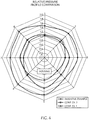
- the three examples were in turn applied to a reinforced rubber hose of about 2.25-inch internal diameter in which a smooth cylindrical mandrel or fitting was inserted. Between the mandrel and hose, a film-type pressure sensor was inserted. The pressure profile between hose and mandrel was recorded at about 31 positions in the circumferential direction by 44 positions in the axial direction, and the average pressure for the positions located directly under the liner was calculated and compared on a normalized basis. The same torque of 30 in-lbs (3.4 N-m) was applied to the worm drive for the inventive example and for comparative examples 1 and 2. The results of this comparison are presented in Table 1. Smoothed pressure profiles for this comparison are shown in FIG. 4 .
- the Comparative Examples are abbreviated as "Comp.
- the results in Table 1 and FIG. 4 illustrate various advantages of the inventive spring liner.
- the average pressure results shown in Table 1 illustrate how the spring liner can amplify the clamp force to increase the radial sealing pressure.
- the 42% increase in average pressure over the clamp with no liner is, however, less than one would predict from the width difference of the inventive liner compared to the band. This short fall is believed due to edge effects and relaxation or compression set effects within the rubber.
- the particular advantages exhibited may be dependent on the details of the hose construction and materials which is being clamped.
- the benefits of the invention, and the comparative advantages relative to the prior art liner may depend on the type of hose and the type of application.
- the prior art liner, with its two ridges may still give higher peak pressures immediately under the ridges.
- some types of hose or application may be better clamped with a higher average pressure, but lower peak pressure.
- FIG. 4 it can be seen that the clamp pressure for the inventive example is higher than the comparative examples for the entire circumference. This should translate to improved sealing performance for the inventive example.
- FIG. 4 also illustrates that the flat spring liner provides more uniform distribution of pressure around the clamp circumference than the comparative example with no liner.
- the variation in the region of the worm-drive housing (near position 5 in FIG. 4 ) Is significantly less when a liner is used than without a liner. This too should translate to improved sealing performance,
Description
- This invention relates generally to the field of hose clamp assemblies, more particularly to a spring liner that Is associated with a hose clamp assembly, and specifically to a spring liner with a central, flat, hose-contact portion.
- Hose clamps are commonly utilized to join together hoses and fittings or connectors (referred to hereinafter as fittings), for example, within the automotive industry. Hose clamps, hose and fittings respond to changes in ambient temperature and system temperatures based on the thermal properties of the aforementioned components. Differing coefficients of thermal expansion of these components can result in thermally-induced reductions in clamping force, thus creating the potential for fluid or gas leakage. In addition, changes in elasticity of the hose materials over time due to creep, compression set, or deterioration can also reduce the clamping force and create the potential for fluid leakage.
- Various types of spring liners used in conjunction with hose clamps are known.
U.S. Pat. Nos. 7,178,204 and7,302,741 are exemplary of the art, disclosing a spring liner having two inward projecting ridges with an outward-projecting ridge in between. The ridges create two zones of very high compression in the hose, while the central ridge area creates a zone of lesser compression. - Mention is also made of a co-pending application by the same applicant titled "Hose Clamp with Rippled Spring Liner," U.S. Application Serial No.
13/188,103 -
DE10061425 discloses a system for attaching an elastomeric hose to a connector comprising a press-fitting or clamp and a locking component nearer the end of the hose. This presses the hose radially against the connector. It may consist of a plastic clip or a shrink-fitted sleeve. -
US4312101 discloses an insert ring for use with a hose clamp of they type provided with a circumferential band portion and with at least one ear projecting outwardly from the band and adapted to be deformed so as to tighten the clamp about the object to be fastened. The insert ring is so constructed and arranged as to prevent the portion of the insert ring underneath a respective ear from escaping outwardly into the opening within the area underneath the ear during contraction of the latter to thereby prevent any leakage within that area of the ear. -
US 2006/0162131 discloses a hose clamp comprising an annular band having an inner face, tensioning means, and an annular spring liner. The spring liner comprises an outwardly-projecting circumferential ridge, an Inwardly-projecting circumferential ridge on each side of said outwardly-projecting ridge, and a circumferential shoulder near an edge of said spring liner. At least one shoulder is adapted to abut the Inner face. - The invention is defined by the claims.
- The present invention provides at least in preferred embodiments, an improved spring liner which allows a hose clamp to self-compensate for changes in elastic properties and diametric changes of the underlying hose and fittings. The invention Is directed to a hose clamp according to
claim 1. The band of the hose clamp seats on the shoulders of the liner when the clamp is tensioned. Thus, at least after assembly, and before tensioning of the hose clamp, the flat central ridge is separated from the inner face of the tensioning band of the hose clamp by a gap of constant thickness. The width of the flat contact portion Is less than the width of the inner face of the tensioning band. The width of the flat contact portion may be in the range from 40% to 75% of the width of the inner face of the tensioning band. - In one embodiment, the spring liner further has on at least a portion of one or both circumferential edges a radially outwardly-flared flange.
- The present invention provides an Improved hose clamp assembly having an annular band having an Inner face, a tensioner disposed to facilitate constriction of the band, and the annular spring liner as described above.
- The foregoing has outlined rather broadly the features and technical advantages of the present invention In order that the detailed description of the invention that follows may be better understood. Additional features and advantages of the invention will be described hereinafter. It should be appreciated by those skilled in the art that the conception and specific embodiment disclosed may be readily utilized as a basis for modifying or designing other structures for carrying out the same purposes of the present Invention. The novel features which are believed to be characteristic of the invention, both as to its organization and method of operation, together with further objects and advantages will be better understood from the following description when considered in connection with the accompanying figures. It is to be expressly understood, however, that each of the figures is provided for the purpose of illustration and description only and is not intended as a definition of the limits of the present invention.
- The accompanying drawings, which are incorporated in and form part of the specification in which like numerals designate like parts, illustrate embodiments of the present invention and together with the description, serve to explain the principles of the invention. In the drawings:
-
FIG. 1 is a perspective exploded view of a hose clamp assembly including clamp and spring liner in accordance with an embodiment of the present invention; -
FIG. 2 is a partial sectional view of the spring liner ofFIG. 1 , taken along section 2-2; -
FIG. 3 is a partially fragmented view of a hose clamp assembly including
spring liner, hose, and fitting in accordance with an embodiment of the present invention; and -
FIG. 4 is a graph of clamp pressure versus position around a hose for an embodiment of the invention and for two comparative examples. - The present invention provides a means of reducing the contact surface area of the inside diameter (ID) of traditional worm-gear hose clamp in order to increase the unit loading the hose clamp assembly imparts to the underlying hose or substrate. The reduction in contact surface area is achieved by the use of a circular liner that is inserted into the ID of a hose clamp or
tensioning band 1. The cross-section of the liner hasshoulders 5 with contact surfaces on their outside diameter (OD) which are together approximately equal in axial extent (width) to the inside surface width of the hose clamp or tensioning band. The edges of the shoulders may project upward towards the hose clamp or tensioning band at angles to hold the liner captive within the hose clamp or tensioning band ID. The profile of the liner also includes a flat,cylindrical contact portion 7 positioned inward or lower thanshoulders 5. By contact is meant thatflat portion 7 is intended to contact the underlying hose or substrate. This surface is narrower than the hose clamp ortensioning band 1 width and may be in the range of 40% to 75% of the hose clamp or tensioning band width. Twolegs 6 bridge between the two shoulders and thelower contact portion 7 of the liner. These legs may be symmetrical and are located on either side of the lower contact surface and project outward at acute angles relative to the clamp centerline, thus reaching to and attaching to the upper shoulders. - The increase in unit loading can also be described as an increase in the radial pressure the clamp exerts on the underlying hose or substrate. The radial pressure (pr) a hose clamp or a tensioned band exerts is a function of the band tension (T), the band width (w) and the clamping diameter (d). For any fixed value of "T" and "d", an increase in "w" will decrease radial pressure, and a decrease in "w" will increase radial pressure. Manipulation of a simplified hoop stress formula can demonstrate this behavior; 2T = pr w d transposes to pr = 2T/(w d).
- In addition to increasing a hose clamp or tension bands' radial pressure as a result of the liner's narrower contact width, the liner also can act as a spring, thus providing a thermal-compensating feature for the clamp. The spring effect will be described in more detail later. First, the drawings will be discussed in more detail.
- Referring to
FIG. 1 , a hose clamp is shown comprising an outerannular band 1, and a typical tensioning means 3, 4.FIG. 1 also shows in exploded viewflat spring liner 9 in accordance with the present invention. In another embodiment, spring liner 19 is shown in section inFIG. 2 .Spring liner 9, as well as spring liner 19, is an annular ring with overlappingends 10.Spring liner 9 and 19 comprise two flat annularcircumferential shoulders 5 near the edges of the liner, a flat central annularcircumferential contact portion 7 located between the twoshoulders 5 and of smaller circumference than the shoulders, and two annularcircumferential legs 6 there between connecting the inner edges ofshoulders 5 to the outer edges offlat contact portion 7.FIG. 2 shows radial height differential A between the twoshoulders 5 and theflat contact portion 7. Whenliner 9 or 19 is inserted intoclamp band 1, the inner face ofband 1 will abut or seat onshoulders 5, and gap A will result between the outer surface ofcontact portion 7 and the inner face ofband 1 in the absence of clamp tensioning forces. Thus,flat portion 7 does not abut the inner face ofband 1 in the absence of clamp tensioning forces. - The terms outward and inward refer to direction with respect to the center axis of the generally circular liner. Inward means directed toward the center axis of the liner. Outward means directed away from the center axis of the liner.
- Upon applying clamp tensioning forces, i.e., tightening or tensioning of the band, the
overlap section 10 of the liner can increase in length, resulting in a decrease in the circumference of the liner. As the band tightens, the liner is thus pulled into compressive engagement with the associated hose.FIG. 3 illustrates the hose clamp assembly in use with ahose 11 and ahose fitting 12.Band 1 of the hose clamp seats on twoshoulders 5. The inward facingflat contact portion 7 of the liner creates a zone of relativelyuniform compression 14 in the hose. - The profile of the liner is designed so that the two
legs 6 can deflect under the compressive forces, creating a spring effect. As the band is tensioned, the deflection of the legs will cause gap A to decrease to A' (A'<A), or perhaps even disappear completely. As the band is tensioned, the deflection may also cause the flat contact surface to deform slightly. The decrease in gap is an indication of the amount of spring energy stored in the annular spring liner. The net effect of these radial and axial deflections and the resulting compression forces on the hose is a much better initial and long term sealing effect than obtained with prior art hose clamp liner designs. - As the hose and clamp assembly is exposed to thermal fluctuations, the spring liner can respond by further deflecting or by relaxing, thus helping to maintain an excellent sealing force on the hose assembly. As the hose material, which is typically vulcanized rubber, takes on a compression set, or inelastic deformation, due to deterioration of elastic properties over time, the force exerted by the rubber will relax or decline, and the spring liner again relaxes or releases some of the stored spring energy, thus maintaining an excellent sealing force on the hose. Compared to prior liner designs with narrow ridges which create zones of very high compression, the present invention creates a more uniform zone of moderate compression, which may advantageously avoid extreme deformations and extreme effects of compression set in the rubber hose being clamped.
- If the hose clamp is tensioned to the extent that gap A' is eliminated and the outer surface of
contact portion 7 contacts the inner surface ofband 1, then any further deflection of the spring liner requires much higher forces, commensurate with a dramatic increase in spring rate. Under this condition, the deflection of the spring liner in response to thermal expansion of the hose is very limited. However, under this condition, the spring liner's ability to relax or respond to thermal contraction of the hose is maximized. Thus, the clamp and spring liner may be designed so that in use, gap A' is maintained even in the presence of clamp tensioning forces. Alternately, the clamp and spring liner may be designed so that in use, the outer surface of theflat contact portion 7 may abut the inner face of thehose clamp 1 in the presence of clamp tensioning forces. - As shown in
FIGS. 2 and 3 , spring liner 19 may also have one or two radially outward flaredflanges 8 to aid in aligning liner 19 withinband 1. The flanges shown in the figures flare outward at about a 45° angle. Any suitable flare angle or flare shape may be used.Flanges 8, as well aslegs 6, may be sharply bent or may have a more rounded, gradual transition from adjoiningshoulders 5 orcontact portion 7.Flanges 8 may extend the entire circumference of the liner or may be cut short in appropriate places to reduce interference in theoverlap section 10 of the liner or to reduce interference between the liner and the tensioning means 3, 4. Alternately, or in addition to a flange, the spring liner may be more or less permanently affixed toband 1 by any means that provides an adequate bond, such as, but not limited to, heat welding, chemical welding, chemical bonding, staking, mechanical fasteners, or a combination of two or more of the foregoing. - The spring force exerted by the liner depends on the thickness and modulus of the material of which it is constructed. The force also depends on the precise profile, i.e. the shape and size of the legs, contact portion, and shoulders. The profile shown in
FIG. 2 , when formed out of sheet metal about 0.012 inches (0.3 mm) thick, is suitable for typical automotive hose clamping applications. One skilled in the art would be able to alter the materials, material properties, shoulder and flat surface dimensions, flange angles, overlap distance, and/or spring liner thickness to optimize the flat spring liner for particular applications. The profile need not be perfectly symmetric. The two shoulders, the legs, and the central flat surface may all be of different sizes. The central flat surface need not be at the exact center of the annular liner. The two leg angles may be different. The thickness of the liner may also vary in the axial direction. - Friction between the overlapping ends of the spring liner can affect the clamping force achieved during assembly. To reduce the friction force, the overlapping ends may be coated with wax or other suitable lubricant. To increase the friction force, the overlapping section may be cleaned, roughened, grooved, knurled, or the like. Thus, one skilled in the art can optimize the friction as needed or desired.
- Any of the various hose clamp tightening or tensioning means, i.e., "tensioner," known in the art may be used. By way of illustration, the tensioning mechanism may be a
worm drive FIG. 1 . Alternatively, the tensioner may be a T-bolt, a ratcheting mechanism, a bolt and barrel mechanism, a nut and bolt assembly, a permanent crimp, or the like, or combinations thereof. Alternatively, the clamp may be an endless band with thermally frozen-in strain, which is tensioned by releasing the strain and allowing the band to shrink onto the spring liner, hose and fitting. In addition, tensioning band or hose clamp width may vary. The proportionality of tensioning band width to liner width and liner contact width may vary. - Other known features of hose clamps may be incorporated if desired without departing from the scope of the invention. For example, various means of attaching the assembly to the hose, such as adhesive, a vulcanizing patch, a locating tab, a locating clip, and the like may be incorporated. Cutouts or apertures for adjusting spring stiffness, or the like may be incorporated.
- In actual practice, a hose clamp with an annular spring liner is placed over the hose and fitting to be joined. Clamp diameter is reduced by means of the tensioning mechanism. Spring liner diameter is reduced proportionally to the clamp diameter reduction by increasing the circumferential overlap length of the liner. As the combined hose clamp and annular spring liner diameters decrease, radial pressure acting on the underlying hose and fitting increase. Because of the shape of the liner, the radial pressure on the hose is amplified from that generated by the clamp alone, while remaining relatively uniform in the hose region under the liner.
- As the radial forces acting on the spring liner increase as a result of increased tension in the outer band, the spring liner deflects in such a manner that the
shoulders 5 deflect downward towards thehose 11. This movement can continue until the desired tension is achieved. However, the movement becomes limited at the point where the centralflat portion 7 contacts (if ever) the inner face of theclamp band 1. The deflections are elastic, spring-like behavior. Therefore, the liner can respond to variations in band tension and/or radial pressures as a spring. This spring behavior insures that the centralflat portion 7 exerts sufficient radial pressure on the hose throughout the life of the clamp installation. - As an example of a possible modification, it is envisioned that in one embodiment of the invention, the inner face of the hose clamp could initially when assembled contact one shoulder of the spring liner, there being a gap between the inner face of the clamp and a second shoulder of the liner. As the hose clamp of this embodiment is tensioned, the gap between the inner face and the second shoulder would close as deformation energy is stored in the spring liner, with the clamp perhaps even finally seating on the second shoulder.
- The following examples illustrate the use and benefits of an embodiment of the invention. For the examples, a hose clamp with worm drive tensioning as shown in
FIG. 1 was obtained. The band had a width of 0.405 inches (10.3 mm) and a nominal diameter of about two and a half inches (about 65 mm). As an inventive example, a spring liner as shown inFIG. 2 was also constructed, having a total width of 0.47 inches (11.9 mm) and a width ofcontact portion 7 of 0.165 inches (4.2 mm), and this was used with the aforementioned hose clamp. As comparative example 1, the hose clamp was used without a spring liner. As comparative example 2, a spring liner having two inward ridges according toU.S. Pat. No. 7,302,741 ,FIG. 2 , was constructed with similar total width and used with the hose clamp. - The three examples were in turn applied to a reinforced rubber hose of about 2.25-inch internal diameter in which a smooth cylindrical mandrel or fitting was inserted. Between the mandrel and hose, a film-type pressure sensor was inserted. The pressure profile between hose and mandrel was recorded at about 31 positions in the circumferential direction by 44 positions in the axial direction, and the average pressure for the positions located directly under the liner was calculated and compared on a normalized basis. The same torque of 30 in-lbs (3.4 N-m) was applied to the worm drive for the inventive example and for comparative examples 1 and 2. The results of this comparison are presented in Table 1. Smoothed pressure profiles for this comparison are shown in
FIG. 4 . The Comparative Examples are abbreviated as "Comp. Ex." inFIG. 4 . The profiles inFIG. 4 were smoothed by averaging all the positions along the axial direction at each of the 31 circumferential positions. Then seven groups of four and one group of three sequential data points of circumferential data were averaged resulting in eight data points for the smoothed circumferential pressure profiles shown inFIG. 4 .Table 1. Inventive Example Comparative Ex. 1 No Liner Comparative Ex. 2 Prior art Liner Average Pressure (normalized) 142 100 105 - The results in Table 1 and
FIG. 4 illustrate various advantages of the inventive spring liner. The average pressure results shown in Table 1 illustrate how the spring liner can amplify the clamp force to increase the radial sealing pressure. The 42% increase in average pressure over the clamp with no liner is, however, less than one would predict from the width difference of the inventive liner compared to the band. This short fall is believed due to edge effects and relaxation or compression set effects within the rubber. As such, the particular advantages exhibited may be dependent on the details of the hose construction and materials which is being clamped. Thus, the benefits of the invention, and the comparative advantages relative to the prior art liner, may depend on the type of hose and the type of application. The prior art liner, with its two ridges may still give higher peak pressures immediately under the ridges. However, some types of hose or application may be better clamped with a higher average pressure, but lower peak pressure. - In
FIG. 4 , it can be seen that the clamp pressure for the inventive example is higher than the comparative examples for the entire circumference. This should translate to improved sealing performance for the inventive example.FIG. 4 also illustrates that the flat spring liner provides more uniform distribution of pressure around the clamp circumference than the comparative example with no liner. The variation in the region of the worm-drive housing (nearposition 5 inFIG. 4 ) Is significantly less when a liner is used than without a liner. This too should translate to improved sealing performance, - As one of ordinary skill in the art will readily appreciate from the disclosure of the present invention, processes, machines, manufacture, compositions of matter, means, methods, or steps, presently existing or later to be developed that perform substantially the same function or achieve substantially the same result as the corresponding embodiments described herein may be utilized according to the present invention.
Claims (6)
- A hose clamp comprising:a band (1) having an inner face configured to engage a circumference of a substrate,a tensioner (3, 4) comprising a worm drive, andan annular spring liner (9, 19) comprising:a flat circumferential shoulder (5) near each axial outer edge of said liner;a central, cylindrical, flat, contact portion (7) extending axially and being of smaller circumference than said shoulders (5); and,a leg (6) bridging between the each shoulder (5) and the central, cylindrical, flat, contact portion (7);wherein both said shoulders (5) are adapted to abut said inner face of said band,wherein said liner deflects elastically under a clamp tensioning force so that a gap (A) defined between the inner face of the band (1) and the flat contact portion (7) varies with said clamp tensioning force.
- The hose clamp of claim 1 wherein said flat contact portion (7) is narrower than said inner face of said band (1) in the absence of clamp tensioning forces.
- The hose clamp of claim 2 wherein said flat contact portion (7) has a width in the range of 40% to 70% of the width of said inner face of said hose clamp.
- The hose clamp of claim 2, further comprising on at least one axial outer edge a radially outwardly flared flange (8).
- The hose clamp of claim 1, further comprising on each axial outer edge a radially outwardly flared flange (8) extending beyond the width of the inner face of said hose clamp.
- The hose clamp of claim 1 wherein said liner has generally circular shape with overlapping circumferential ends.
Priority Applications (1)
| Application Number | Priority Date | Filing Date | Title |
|---|---|---|---|
| EP19197195.1A EP3650738B1 (en) | 2011-07-21 | 2012-07-20 | Hose clamp assembly with flat spring liner and method of installing it |
Applications Claiming Priority (2)
| Application Number | Priority Date | Filing Date | Title |
|---|---|---|---|
| US13/188,093 US8650719B2 (en) | 2011-07-21 | 2011-07-21 | Hose clamp with flat spring liner |
| PCT/US2012/047597 WO2013013149A1 (en) | 2011-07-21 | 2012-07-20 | Hose clamp with flat spring liner |
Related Child Applications (1)
| Application Number | Title | Priority Date | Filing Date |
|---|---|---|---|
| EP19197195.1A Division EP3650738B1 (en) | 2011-07-21 | 2012-07-20 | Hose clamp assembly with flat spring liner and method of installing it |
Publications (3)
| Publication Number | Publication Date |
|---|---|
| EP2734766A1 EP2734766A1 (en) | 2014-05-28 |
| EP2734766A4 EP2734766A4 (en) | 2015-03-18 |
| EP2734766B1 true EP2734766B1 (en) | 2019-09-18 |
Family
ID=47554708
Family Applications (2)
| Application Number | Title | Priority Date | Filing Date |
|---|---|---|---|
| EP19197195.1A Active EP3650738B1 (en) | 2011-07-21 | 2012-07-20 | Hose clamp assembly with flat spring liner and method of installing it |
| EP12814366.6A Active EP2734766B1 (en) | 2011-07-21 | 2012-07-20 | Hose clamp with flat spring liner |
Family Applications Before (1)
| Application Number | Title | Priority Date | Filing Date |
|---|---|---|---|
| EP19197195.1A Active EP3650738B1 (en) | 2011-07-21 | 2012-07-20 | Hose clamp assembly with flat spring liner and method of installing it |
Country Status (9)
| Country | Link |
|---|---|
| US (5) | US8650719B2 (en) |
| EP (2) | EP3650738B1 (en) |
| JP (2) | JP6117201B2 (en) |
| KR (2) | KR20180077328A (en) |
| CN (4) | CN203068013U (en) |
| CA (1) | CA2842512C (en) |
| ES (2) | ES2753182T3 (en) |
| RU (1) | RU2599695C2 (en) |
| WO (1) | WO2013013149A1 (en) |
Families Citing this family (10)
| Publication number | Priority date | Publication date | Assignee | Title |
|---|---|---|---|---|
| US8650719B2 (en) | 2011-07-21 | 2014-02-18 | Ideal Clamp Products, Inc. | Hose clamp with flat spring liner |
| CN104482344A (en) * | 2014-10-29 | 2015-04-01 | 张明 | Hose clamp with ripple spring inner lining |
| CN105465520A (en) * | 2015-12-08 | 2016-04-06 | 天津市凯诺实业有限公司 | High-repeated-use hose clamp |
| WO2017117187A1 (en) | 2015-12-28 | 2017-07-06 | Ideal Clamp Products, Inc. | Hose clamp bracket with positioning features |
| US20180340557A1 (en) * | 2017-05-26 | 2018-11-29 | Ideal Clamp Products, Inc. | Hose clamp with indicator |
| US10495244B2 (en) | 2017-08-20 | 2019-12-03 | Mann+Hummel Gmbh | Positionally fixed clamp and a hose or duct having a positionally fixed clamp |
| CN107420654A (en) * | 2017-10-10 | 2017-12-01 | 季永东 | Flexible pipe and grip device, clamp member and method |
| MX2020004508A (en) | 2017-11-15 | 2020-08-13 | Ideal Clamp Products Inc | Hose clamp with spring liner and method. |
| WO2021083519A1 (en) | 2019-10-30 | 2021-05-06 | Oetiker Schweiz Ag | Clamp with indentations in an insert |
| CN112096990B (en) * | 2020-09-30 | 2022-06-14 | 南京润驰橡胶制品有限公司 | Disconnect-type high pressure hydraulic hose connector |
Family Cites Families (24)
| Publication number | Priority date | Publication date | Assignee | Title |
|---|---|---|---|---|
| US2089940A (en) | 1935-07-17 | 1937-08-17 | Du Pont | Coupling device for collapsible tubes |
| US3142881A (en) | 1962-06-06 | 1964-08-04 | Alva J Johnston | Hose clamp |
| CH405027A (en) | 1963-01-29 | 1965-12-31 | Oetiker Hans | Hose clamp |
| US3233922A (en) * | 1963-07-29 | 1966-02-08 | Cast Iron Soil Pipe Inst | Pipe joint |
| US4312101A (en) * | 1978-09-26 | 1982-01-26 | Hans Oetiker | Hose clamp with insert member |
| US4310956A (en) | 1979-02-05 | 1982-01-19 | Meckstroth Alan F | Hose clamp with tangential screw |
| US4308648A (en) | 1980-03-31 | 1982-01-05 | Murray Corporation | Convoluted hose clamps |
| SE445065B (en) | 1983-12-23 | 1986-05-26 | Allmaenna Brandredskapsaffaere | SLANGKLEMMA |
| USD285171S (en) | 1984-07-26 | 1986-08-19 | Western Filament, Inc. | Clamp sleeve |
| US5195788A (en) | 1990-01-30 | 1993-03-23 | Hans Oetiker | Insert member for use with hose clamp arrangements |
| DE4005631A1 (en) | 1990-02-22 | 1991-09-05 | Rasmussen Gmbh | HOSE CLAMP |
| US5220710A (en) | 1991-08-15 | 1993-06-22 | Ta Mfg. Co. | Cable clamp |
| JPH0726712B2 (en) | 1991-08-16 | 1995-03-29 | ラスムッセン ジイエムビイエイチ | Hose clip |
| SE500904C2 (en) | 1993-09-15 | 1994-09-26 | Aba Sweden Ab | Device for hose clamps |
| CN2234031Y (en) | 1995-10-06 | 1996-08-28 | 金惠民 | Guard staple type pipe coupling |
| GB2326920A (en) | 1997-07-01 | 1999-01-06 | Rasmussen Gmbh | Clamp for clamping a hose on a pipe portion |
| DE19806235A1 (en) * | 1998-02-16 | 1999-09-09 | Rasmussen Gmbh | Clamp arrangement |
| DE10061425A1 (en) * | 2000-12-09 | 2002-06-13 | Bayerische Motoren Werke Ag | System for attaching elastomeric hose to connector comprises press-fitting or clamp and locking component nearer end of hose which presses hose radially against connector, even at temperatures below freezing point of elastomer |
| US6877191B2 (en) | 2001-09-17 | 2005-04-12 | Dwws, Llc | Band clamp |
| US7178204B2 (en) | 2005-01-27 | 2007-02-20 | Epicor Industries, Inc. | Hose clamp and spring liner |
| US7389568B2 (en) | 2005-07-27 | 2008-06-24 | Epicor Industries, Inc. | Compression hose clamp |
| DE102006048336B4 (en) * | 2006-10-12 | 2013-07-04 | Norma Germany Gmbh | hose clamp |
| ES2389133T3 (en) | 2007-11-09 | 2012-10-23 | Progeral Indústria de Artefatos Plásticos Ltda. | Hose clamp |
| US8650719B2 (en) | 2011-07-21 | 2014-02-18 | Ideal Clamp Products, Inc. | Hose clamp with flat spring liner |
-
2011
- 2011-07-21 US US13/188,093 patent/US8650719B2/en active Active
-
2012
- 2012-07-20 CN CN201220356117XU patent/CN203068013U/en not_active Expired - Fee Related
- 2012-07-20 CN CN201710013027.8A patent/CN106907540B/en active Active
- 2012-07-20 RU RU2014106428/06A patent/RU2599695C2/en active
- 2012-07-20 CA CA2842512A patent/CA2842512C/en active Active
- 2012-07-20 WO PCT/US2012/047597 patent/WO2013013149A1/en active Application Filing
- 2012-07-20 EP EP19197195.1A patent/EP3650738B1/en active Active
- 2012-07-20 ES ES12814366T patent/ES2753182T3/en active Active
- 2012-07-20 JP JP2014521823A patent/JP6117201B2/en active Active
- 2012-07-20 CN CN201320337213.4U patent/CN203549132U/en not_active Expired - Fee Related
- 2012-07-20 ES ES19197195T patent/ES2930071T3/en active Active
- 2012-07-20 KR KR1020187018510A patent/KR20180077328A/en active Search and Examination
- 2012-07-20 CN CN201280045766.0A patent/CN103827566B/en active Active
- 2012-07-20 EP EP12814366.6A patent/EP2734766B1/en active Active
- 2012-07-20 KR KR1020147004482A patent/KR20140057279A/en active Search and Examination
-
2014
- 2014-02-17 US US14/181,892 patent/US9447903B2/en active Active
-
2016
- 2016-09-20 US US15/270,140 patent/US10036501B2/en active Active
-
2017
- 2017-03-21 JP JP2017054794A patent/JP6800791B2/en active Active
-
2018
- 2018-07-30 US US16/049,051 patent/US10527211B2/en active Active
-
2020
- 2020-01-07 US US16/736,556 patent/US10969044B2/en active Active
Non-Patent Citations (1)
| Title |
|---|
| None * |
Also Published As
Similar Documents
| Publication | Publication Date | Title |
|---|---|---|
| US10969044B2 (en) | Clamp assemblies and methods | |
| EP2734767B1 (en) | Hose clamp with rippled spring liner | |
| US7178204B2 (en) | Hose clamp and spring liner | |
| US7948146B2 (en) | Clip |
Legal Events
| Date | Code | Title | Description |
|---|---|---|---|
| PUAI | Public reference made under article 153(3) epc to a published international application that has entered the european phase |
Free format text: ORIGINAL CODE: 0009012 |
|
| 17P | Request for examination filed |
Effective date: 20140214 |
|
| AK | Designated contracting states |
Kind code of ref document: A1 Designated state(s): AL AT BE BG CH CY CZ DE DK EE ES FI FR GB GR HR HU IE IS IT LI LT LU LV MC MK MT NL NO PL PT RO RS SE SI SK SM TR |
|
| DAX | Request for extension of the european patent (deleted) | ||
| A4 | Supplementary search report drawn up and despatched |
Effective date: 20150212 |
|
| RIC1 | Information provided on ipc code assigned before grant |
Ipc: F16L 33/02 20060101ALI20150206BHEP Ipc: F16L 33/08 20060101AFI20150206BHEP |
|
| STAA | Information on the status of an ep patent application or granted ep patent |
Free format text: STATUS: EXAMINATION IS IN PROGRESS |
|
| 17Q | First examination report despatched |
Effective date: 20171103 |
|
| GRAP | Despatch of communication of intention to grant a patent |
Free format text: ORIGINAL CODE: EPIDOSNIGR1 |
|
| STAA | Information on the status of an ep patent application or granted ep patent |
Free format text: STATUS: GRANT OF PATENT IS INTENDED |
|
| INTG | Intention to grant announced |
Effective date: 20190401 |
|
| GRAS | Grant fee paid |
Free format text: ORIGINAL CODE: EPIDOSNIGR3 |
|
| GRAA | (expected) grant |
Free format text: ORIGINAL CODE: 0009210 |
|
| STAA | Information on the status of an ep patent application or granted ep patent |
Free format text: STATUS: THE PATENT HAS BEEN GRANTED |
|
| AK | Designated contracting states |
Kind code of ref document: B1 Designated state(s): AL AT BE BG CH CY CZ DE DK EE ES FI FR GB GR HR HU IE IS IT LI LT LU LV MC MK MT NL NO PL PT RO RS SE SI SK SM TR |
|
| REG | Reference to a national code |
Ref country code: GB Ref legal event code: FG4D |
|
| REG | Reference to a national code |
Ref country code: CH Ref legal event code: EP |
|
| REG | Reference to a national code |
Ref country code: DE Ref legal event code: R096 Ref document number: 602012064167 Country of ref document: DE |
|
| REG | Reference to a national code |
Ref country code: AT Ref legal event code: REF Ref document number: 1181739 Country of ref document: AT Kind code of ref document: T Effective date: 20191015 |
|
| REG | Reference to a national code |
Ref country code: IE Ref legal event code: FG4D |
|
| REG | Reference to a national code |
Ref country code: SE Ref legal event code: TRGR |
|
| REG | Reference to a national code |
Ref country code: NL Ref legal event code: MP Effective date: 20190918 |
|
| PG25 | Lapsed in a contracting state [announced via postgrant information from national office to epo] |
Ref country code: FI Free format text: LAPSE BECAUSE OF FAILURE TO SUBMIT A TRANSLATION OF THE DESCRIPTION OR TO PAY THE FEE WITHIN THE PRESCRIBED TIME-LIMIT Effective date: 20190918 Ref country code: LT Free format text: LAPSE BECAUSE OF FAILURE TO SUBMIT A TRANSLATION OF THE DESCRIPTION OR TO PAY THE FEE WITHIN THE PRESCRIBED TIME-LIMIT Effective date: 20190918 Ref country code: BG Free format text: LAPSE BECAUSE OF FAILURE TO SUBMIT A TRANSLATION OF THE DESCRIPTION OR TO PAY THE FEE WITHIN THE PRESCRIBED TIME-LIMIT Effective date: 20191218 Ref country code: NO Free format text: LAPSE BECAUSE OF FAILURE TO SUBMIT A TRANSLATION OF THE DESCRIPTION OR TO PAY THE FEE WITHIN THE PRESCRIBED TIME-LIMIT Effective date: 20191218 Ref country code: HR Free format text: LAPSE BECAUSE OF FAILURE TO SUBMIT A TRANSLATION OF THE DESCRIPTION OR TO PAY THE FEE WITHIN THE PRESCRIBED TIME-LIMIT Effective date: 20190918 |
|
| REG | Reference to a national code |
Ref country code: LT Ref legal event code: MG4D |
|
| PG25 | Lapsed in a contracting state [announced via postgrant information from national office to epo] |
Ref country code: RS Free format text: LAPSE BECAUSE OF FAILURE TO SUBMIT A TRANSLATION OF THE DESCRIPTION OR TO PAY THE FEE WITHIN THE PRESCRIBED TIME-LIMIT Effective date: 20190918 Ref country code: GR Free format text: LAPSE BECAUSE OF FAILURE TO SUBMIT A TRANSLATION OF THE DESCRIPTION OR TO PAY THE FEE WITHIN THE PRESCRIBED TIME-LIMIT Effective date: 20191219 Ref country code: LV Free format text: LAPSE BECAUSE OF FAILURE TO SUBMIT A TRANSLATION OF THE DESCRIPTION OR TO PAY THE FEE WITHIN THE PRESCRIBED TIME-LIMIT Effective date: 20190918 Ref country code: AL Free format text: LAPSE BECAUSE OF FAILURE TO SUBMIT A TRANSLATION OF THE DESCRIPTION OR TO PAY THE FEE WITHIN THE PRESCRIBED TIME-LIMIT Effective date: 20190918 |
|
| REG | Reference to a national code |
Ref country code: ES Ref legal event code: FG2A Ref document number: 2753182 Country of ref document: ES Kind code of ref document: T3 Effective date: 20200407 |
|
| REG | Reference to a national code |
Ref country code: AT Ref legal event code: MK05 Ref document number: 1181739 Country of ref document: AT Kind code of ref document: T Effective date: 20190918 |
|
| PG25 | Lapsed in a contracting state [announced via postgrant information from national office to epo] |
Ref country code: PL Free format text: LAPSE BECAUSE OF FAILURE TO SUBMIT A TRANSLATION OF THE DESCRIPTION OR TO PAY THE FEE WITHIN THE PRESCRIBED TIME-LIMIT Effective date: 20190918 Ref country code: AT Free format text: LAPSE BECAUSE OF FAILURE TO SUBMIT A TRANSLATION OF THE DESCRIPTION OR TO PAY THE FEE WITHIN THE PRESCRIBED TIME-LIMIT Effective date: 20190918 Ref country code: EE Free format text: LAPSE BECAUSE OF FAILURE TO SUBMIT A TRANSLATION OF THE DESCRIPTION OR TO PAY THE FEE WITHIN THE PRESCRIBED TIME-LIMIT Effective date: 20190918 Ref country code: PT Free format text: LAPSE BECAUSE OF FAILURE TO SUBMIT A TRANSLATION OF THE DESCRIPTION OR TO PAY THE FEE WITHIN THE PRESCRIBED TIME-LIMIT Effective date: 20200120 Ref country code: RO Free format text: LAPSE BECAUSE OF FAILURE TO SUBMIT A TRANSLATION OF THE DESCRIPTION OR TO PAY THE FEE WITHIN THE PRESCRIBED TIME-LIMIT Effective date: 20190918 Ref country code: NL Free format text: LAPSE BECAUSE OF FAILURE TO SUBMIT A TRANSLATION OF THE DESCRIPTION OR TO PAY THE FEE WITHIN THE PRESCRIBED TIME-LIMIT Effective date: 20190918 |
|
| PG25 | Lapsed in a contracting state [announced via postgrant information from national office to epo] |
Ref country code: SK Free format text: LAPSE BECAUSE OF FAILURE TO SUBMIT A TRANSLATION OF THE DESCRIPTION OR TO PAY THE FEE WITHIN THE PRESCRIBED TIME-LIMIT Effective date: 20190918 Ref country code: CZ Free format text: LAPSE BECAUSE OF FAILURE TO SUBMIT A TRANSLATION OF THE DESCRIPTION OR TO PAY THE FEE WITHIN THE PRESCRIBED TIME-LIMIT Effective date: 20190918 Ref country code: IS Free format text: LAPSE BECAUSE OF FAILURE TO SUBMIT A TRANSLATION OF THE DESCRIPTION OR TO PAY THE FEE WITHIN THE PRESCRIBED TIME-LIMIT Effective date: 20200224 Ref country code: SM Free format text: LAPSE BECAUSE OF FAILURE TO SUBMIT A TRANSLATION OF THE DESCRIPTION OR TO PAY THE FEE WITHIN THE PRESCRIBED TIME-LIMIT Effective date: 20190918 |
|
| REG | Reference to a national code |
Ref country code: DE Ref legal event code: R097 Ref document number: 602012064167 Country of ref document: DE |
|
| PLBE | No opposition filed within time limit |
Free format text: ORIGINAL CODE: 0009261 |
|
| STAA | Information on the status of an ep patent application or granted ep patent |
Free format text: STATUS: NO OPPOSITION FILED WITHIN TIME LIMIT |
|
| PG2D | Information on lapse in contracting state deleted |
Ref country code: IS |
|
| PG25 | Lapsed in a contracting state [announced via postgrant information from national office to epo] |
Ref country code: DK Free format text: LAPSE BECAUSE OF FAILURE TO SUBMIT A TRANSLATION OF THE DESCRIPTION OR TO PAY THE FEE WITHIN THE PRESCRIBED TIME-LIMIT Effective date: 20190918 Ref country code: IS Free format text: LAPSE BECAUSE OF FAILURE TO SUBMIT A TRANSLATION OF THE DESCRIPTION OR TO PAY THE FEE WITHIN THE PRESCRIBED TIME-LIMIT Effective date: 20200119 |
|
| 26N | No opposition filed |
Effective date: 20200619 |
|
| PG25 | Lapsed in a contracting state [announced via postgrant information from national office to epo] |
Ref country code: SI Free format text: LAPSE BECAUSE OF FAILURE TO SUBMIT A TRANSLATION OF THE DESCRIPTION OR TO PAY THE FEE WITHIN THE PRESCRIBED TIME-LIMIT Effective date: 20190918 |
|
| PG25 | Lapsed in a contracting state [announced via postgrant information from national office to epo] |
Ref country code: MC Free format text: LAPSE BECAUSE OF FAILURE TO SUBMIT A TRANSLATION OF THE DESCRIPTION OR TO PAY THE FEE WITHIN THE PRESCRIBED TIME-LIMIT Effective date: 20190918 |
|
| REG | Reference to a national code |
Ref country code: CH Ref legal event code: PL |
|
| REG | Reference to a national code |
Ref country code: BE Ref legal event code: MM Effective date: 20200731 |
|
| PG25 | Lapsed in a contracting state [announced via postgrant information from national office to epo] |
Ref country code: LU Free format text: LAPSE BECAUSE OF NON-PAYMENT OF DUE FEES Effective date: 20200720 Ref country code: LI Free format text: LAPSE BECAUSE OF NON-PAYMENT OF DUE FEES Effective date: 20200731 Ref country code: CH Free format text: LAPSE BECAUSE OF NON-PAYMENT OF DUE FEES Effective date: 20200731 |
|
| PG25 | Lapsed in a contracting state [announced via postgrant information from national office to epo] |
Ref country code: BE Free format text: LAPSE BECAUSE OF NON-PAYMENT OF DUE FEES Effective date: 20200731 |
|
| PG25 | Lapsed in a contracting state [announced via postgrant information from national office to epo] |
Ref country code: IE Free format text: LAPSE BECAUSE OF NON-PAYMENT OF DUE FEES Effective date: 20200720 |
|
| PG25 | Lapsed in a contracting state [announced via postgrant information from national office to epo] |
Ref country code: MT Free format text: LAPSE BECAUSE OF FAILURE TO SUBMIT A TRANSLATION OF THE DESCRIPTION OR TO PAY THE FEE WITHIN THE PRESCRIBED TIME-LIMIT Effective date: 20190918 Ref country code: CY Free format text: LAPSE BECAUSE OF FAILURE TO SUBMIT A TRANSLATION OF THE DESCRIPTION OR TO PAY THE FEE WITHIN THE PRESCRIBED TIME-LIMIT Effective date: 20190918 |
|
| PG25 | Lapsed in a contracting state [announced via postgrant information from national office to epo] |
Ref country code: MK Free format text: LAPSE BECAUSE OF FAILURE TO SUBMIT A TRANSLATION OF THE DESCRIPTION OR TO PAY THE FEE WITHIN THE PRESCRIBED TIME-LIMIT Effective date: 20190918 |
|
| PGFP | Annual fee paid to national office [announced via postgrant information from national office to epo] |
Ref country code: TR Payment date: 20230707 Year of fee payment: 12 Ref country code: IT Payment date: 20230720 Year of fee payment: 12 Ref country code: GB Payment date: 20230727 Year of fee payment: 12 Ref country code: ES Payment date: 20230804 Year of fee payment: 12 |
|
| PGFP | Annual fee paid to national office [announced via postgrant information from national office to epo] |
Ref country code: SE Payment date: 20230727 Year of fee payment: 12 Ref country code: FR Payment date: 20230725 Year of fee payment: 12 Ref country code: DE Payment date: 20230727 Year of fee payment: 12 |