KR20180041776A - Refrigerator and camera device - Google Patents
Refrigerator and camera device Download PDFInfo
- Publication number
- KR20180041776A KR20180041776A KR1020187010793A KR20187010793A KR20180041776A KR 20180041776 A KR20180041776 A KR 20180041776A KR 1020187010793 A KR1020187010793 A KR 1020187010793A KR 20187010793 A KR20187010793 A KR 20187010793A KR 20180041776 A KR20180041776 A KR 20180041776A
- Authority
- KR
- South Korea
- Prior art keywords
- imaging
- camera
- refrigerator
- door
- image
- Prior art date
Links
Images


Classifications
-
- F—MECHANICAL ENGINEERING; LIGHTING; HEATING; WEAPONS; BLASTING
- F25—REFRIGERATION OR COOLING; COMBINED HEATING AND REFRIGERATION SYSTEMS; HEAT PUMP SYSTEMS; MANUFACTURE OR STORAGE OF ICE; LIQUEFACTION SOLIDIFICATION OF GASES
- F25D—REFRIGERATORS; COLD ROOMS; ICE-BOXES; COOLING OR FREEZING APPARATUS NOT OTHERWISE PROVIDED FOR
- F25D29/00—Arrangement or mounting of control or safety devices
- F25D29/003—Arrangement or mounting of control or safety devices for movable devices
-
- F—MECHANICAL ENGINEERING; LIGHTING; HEATING; WEAPONS; BLASTING
- F25—REFRIGERATION OR COOLING; COMBINED HEATING AND REFRIGERATION SYSTEMS; HEAT PUMP SYSTEMS; MANUFACTURE OR STORAGE OF ICE; LIQUEFACTION SOLIDIFICATION OF GASES
- F25D—REFRIGERATORS; COLD ROOMS; ICE-BOXES; COOLING OR FREEZING APPARATUS NOT OTHERWISE PROVIDED FOR
- F25D23/00—General constructional features
- F25D23/02—Doors; Covers
- F25D23/04—Doors; Covers with special compartments, e.g. butter conditioners
-
- F—MECHANICAL ENGINEERING; LIGHTING; HEATING; WEAPONS; BLASTING
- F25—REFRIGERATION OR COOLING; COMBINED HEATING AND REFRIGERATION SYSTEMS; HEAT PUMP SYSTEMS; MANUFACTURE OR STORAGE OF ICE; LIQUEFACTION SOLIDIFICATION OF GASES
- F25D—REFRIGERATORS; COLD ROOMS; ICE-BOXES; COOLING OR FREEZING APPARATUS NOT OTHERWISE PROVIDED FOR
- F25D23/00—General constructional features
- F25D23/02—Doors; Covers
- F25D23/028—Details
-
- F—MECHANICAL ENGINEERING; LIGHTING; HEATING; WEAPONS; BLASTING
- F25—REFRIGERATION OR COOLING; COMBINED HEATING AND REFRIGERATION SYSTEMS; HEAT PUMP SYSTEMS; MANUFACTURE OR STORAGE OF ICE; LIQUEFACTION SOLIDIFICATION OF GASES
- F25D—REFRIGERATORS; COLD ROOMS; ICE-BOXES; COOLING OR FREEZING APPARATUS NOT OTHERWISE PROVIDED FOR
- F25D11/00—Self-contained movable devices, e.g. domestic refrigerators
-
- F—MECHANICAL ENGINEERING; LIGHTING; HEATING; WEAPONS; BLASTING
- F25—REFRIGERATION OR COOLING; COMBINED HEATING AND REFRIGERATION SYSTEMS; HEAT PUMP SYSTEMS; MANUFACTURE OR STORAGE OF ICE; LIQUEFACTION SOLIDIFICATION OF GASES
- F25D—REFRIGERATORS; COLD ROOMS; ICE-BOXES; COOLING OR FREEZING APPARATUS NOT OTHERWISE PROVIDED FOR
- F25D23/00—General constructional features
- F25D23/02—Doors; Covers
-
- F—MECHANICAL ENGINEERING; LIGHTING; HEATING; WEAPONS; BLASTING
- F25—REFRIGERATION OR COOLING; COMBINED HEATING AND REFRIGERATION SYSTEMS; HEAT PUMP SYSTEMS; MANUFACTURE OR STORAGE OF ICE; LIQUEFACTION SOLIDIFICATION OF GASES
- F25D—REFRIGERATORS; COLD ROOMS; ICE-BOXES; COOLING OR FREEZING APPARATUS NOT OTHERWISE PROVIDED FOR
- F25D23/00—General constructional features
- F25D23/12—Arrangements of compartments additional to cooling compartments; Combinations of refrigerators with other equipment, e.g. stove
-
- F—MECHANICAL ENGINEERING; LIGHTING; HEATING; WEAPONS; BLASTING
- F25—REFRIGERATION OR COOLING; COMBINED HEATING AND REFRIGERATION SYSTEMS; HEAT PUMP SYSTEMS; MANUFACTURE OR STORAGE OF ICE; LIQUEFACTION SOLIDIFICATION OF GASES
- F25D—REFRIGERATORS; COLD ROOMS; ICE-BOXES; COOLING OR FREEZING APPARATUS NOT OTHERWISE PROVIDED FOR
- F25D27/00—Lighting arrangements
-
- F—MECHANICAL ENGINEERING; LIGHTING; HEATING; WEAPONS; BLASTING
- F25—REFRIGERATION OR COOLING; COMBINED HEATING AND REFRIGERATION SYSTEMS; HEAT PUMP SYSTEMS; MANUFACTURE OR STORAGE OF ICE; LIQUEFACTION SOLIDIFICATION OF GASES
- F25D—REFRIGERATORS; COLD ROOMS; ICE-BOXES; COOLING OR FREEZING APPARATUS NOT OTHERWISE PROVIDED FOR
- F25D29/00—Arrangement or mounting of control or safety devices
- F25D29/005—Mounting of control devices
-
- F—MECHANICAL ENGINEERING; LIGHTING; HEATING; WEAPONS; BLASTING
- F25—REFRIGERATION OR COOLING; COMBINED HEATING AND REFRIGERATION SYSTEMS; HEAT PUMP SYSTEMS; MANUFACTURE OR STORAGE OF ICE; LIQUEFACTION SOLIDIFICATION OF GASES
- F25D—REFRIGERATORS; COLD ROOMS; ICE-BOXES; COOLING OR FREEZING APPARATUS NOT OTHERWISE PROVIDED FOR
- F25D2400/00—General features of, or devices for refrigerators, cold rooms, ice-boxes, or for cooling or freezing apparatus not covered by any other subclass
- F25D2400/36—Visual displays
-
- F—MECHANICAL ENGINEERING; LIGHTING; HEATING; WEAPONS; BLASTING
- F25—REFRIGERATION OR COOLING; COMBINED HEATING AND REFRIGERATION SYSTEMS; HEAT PUMP SYSTEMS; MANUFACTURE OR STORAGE OF ICE; LIQUEFACTION SOLIDIFICATION OF GASES
- F25D—REFRIGERATORS; COLD ROOMS; ICE-BOXES; COOLING OR FREEZING APPARATUS NOT OTHERWISE PROVIDED FOR
- F25D2500/00—Problems to be solved
- F25D2500/06—Stock management
-
- F—MECHANICAL ENGINEERING; LIGHTING; HEATING; WEAPONS; BLASTING
- F25—REFRIGERATION OR COOLING; COMBINED HEATING AND REFRIGERATION SYSTEMS; HEAT PUMP SYSTEMS; MANUFACTURE OR STORAGE OF ICE; LIQUEFACTION SOLIDIFICATION OF GASES
- F25D—REFRIGERATORS; COLD ROOMS; ICE-BOXES; COOLING OR FREEZING APPARATUS NOT OTHERWISE PROVIDED FOR
- F25D2700/00—Means for sensing or measuring; Sensors therefor
- F25D2700/08—Sensors using Radio Frequency Identification [RFID]
-
- Y—GENERAL TAGGING OF NEW TECHNOLOGICAL DEVELOPMENTS; GENERAL TAGGING OF CROSS-SECTIONAL TECHNOLOGIES SPANNING OVER SEVERAL SECTIONS OF THE IPC; TECHNICAL SUBJECTS COVERED BY FORMER USPC CROSS-REFERENCE ART COLLECTIONS [XRACs] AND DIGESTS
- Y02—TECHNOLOGIES OR APPLICATIONS FOR MITIGATION OR ADAPTATION AGAINST CLIMATE CHANGE
- Y02B—CLIMATE CHANGE MITIGATION TECHNOLOGIES RELATED TO BUILDINGS, e.g. HOUSING, HOUSE APPLIANCES OR RELATED END-USER APPLICATIONS
- Y02B40/00—Technologies aiming at improving the efficiency of home appliances, e.g. induction cooking or efficient technologies for refrigerators, freezers or dish washers
-
- Y02B40/30—
Landscapes
- Engineering & Computer Science (AREA)
- Chemical & Material Sciences (AREA)
- Combustion & Propulsion (AREA)
- Physics & Mathematics (AREA)
- Mechanical Engineering (AREA)
- Thermal Sciences (AREA)
- General Engineering & Computer Science (AREA)
- Cold Air Circulating Systems And Constructional Details In Refrigerators (AREA)
Abstract
냉장고(1)는, 저장고(예를 들어 냉장실(3)의 고내를 촬상하는 촬상 카메라(18)(촬상수단)와, 해당 촬상 카메라(18)에서 촬상한 고내의 화상을 외부의 장치에 송신하기 위한 통신부(52)(통신수단)를 구비하고, 촬상수단은 고내에 설치된 오목부에 수납되어 있다.The refrigerator 1 includes an image capturing camera 18 (image capturing means) for capturing an image of the interior of a storage room (for example, the inside of the refrigerator compartment 3), and an image capturing device (Communication means), and the image pickup means is housed in a recess provided in the hull.
Description
본 발명의 실시형태는 냉장고 및 카메라 장치에 관한 것이다.An embodiment of the present invention relates to a refrigerator and a camera device.
종래 고내를 촬상하여 식재료를 인식함으로써 식재료를 관리하는 시스템이 제안되어 있다(예를 들어, 특허 문헌 1참조).Conventionally, a system has been proposed in which food ingredients are managed by sensing the inside of a room and recognizing the ingredients (see, for example, Patent Document 1).
그러나, 외출지 등 원격지에서 냉장고의 고내를 확인하고 싶어하는 사용자가 존재한다.However, there is a user who wants to check the inside of the refrigerator at a remote place such as the outing place.
본 발명이 해결하고자 하는 과제는 원격지에서 용이하게 고내를 확인할 수 있는 냉장고, 카메라 장치를 제공하는 것이다.SUMMARY OF THE INVENTION It is an object of the present invention to provide a refrigerator and a camera device that can easily check the inside of a living room from a remote place.
실시형태에 의한 냉장고는 고내를 촬상하기 위한 촬상 수단과, 촬상 수단으로 촬상한 고내의 화상 정보를 외부 장치에 송신하기 위한 통신수단을 구비한다. 그리고, 촬상 수단은 고내에 설치된 오목부에 수납되어 있다.A refrigerator according to an embodiment of the present invention includes imaging means for imaging an interior of a living room and communication means for transmitting image information in the living room imaged by the imaging means to an external device. The imaging means is accommodated in a recess provided in the cavity.
실시형태에 의한 카메라 장치는 냉장고 고내를 촬상하기 위한 촬상 수단과 외부 장치와 통신하기 위한 카메라측 통신수단을 구비한다.The camera device according to the embodiment includes imaging means for imaging the interior of the refrigerator and camera side communication means for communicating with the external device.
도 1은 제1 실시형태의 냉장고를 채용한 가전 네트워크 시스템의 구성 개요를 나타내는 도면이다.
도 2는 제1 실시형태의 냉장고를 모식적으로 나타내는 도면이다.
도 3은 제1 실시형태의 촬상 카메라의 부착 형태를 모식적으로 나타내는 도면이다.
도 4는 제1 실시형태의 냉장고의 구성을 모식적으로 나타내는 도면이다.
도 5는 제1 실시형태의 냉장고 고내의 상태를 모식적으로 나타내는 도면이다.
도 6은 제1 실시형태의 냉장고에 의한 촬상 처리의 흐름을 나타내는 도면이다.
도 7은 제1 실시형태의 촬상 카메라로 촬상한 화상의 일례를 나타내는 도면이다.
도 8은 제1 실시형태의 촬상 카메라의 결로 상태의 변화를 모식적으로 나타내는 도면이다.
도 9는 제1 실시형태의 촬상 카메라에 의한 촬상 시퀀스를 나타내는 도면이다.
도 10은 제1 실시형태의 통신 단말에 의한 단말측 처리의 흐름을 나타내는 도면
도 11은 제1 실시형태의 통신 단말에서의 화상 표시 형태의 일례를 나타내는 도면 그 1이다.
도 12는 제1 실시형태의 통신 단말에서의 화상 표시 형태의 일례를 나타내는 도면 그 2이다.
도 13은 제2 실시형태의 냉장고용 도어 포켓에 카메라 장치를 설치한 형태를 모식적으로 나타내는 도면이다.
도 14는 제2 실시형태의 냉장고용 도어 포켓을 냉장고에 설치한 형태를 모식적으로 나타내는 도면이다.
도 15는 제2 실시형태의 카메라 장치의 외관을 모식적으로 나타내는 도면이다.
도 16은 제2 실시형태의 카메라 장치의 외관 및 내부의 부품 배치를 모식적으로 나타내는 도면이다.
도 17은 제2 실시형태의 카메라 장치를 냉장고용 도어 포켓에 설치한 형태를 모식적으로 나타내는 도면이다.
도 18은 제2 실시형태의 냉장고용 홀더를 설치하는 위치를 모식적으로 나타내는 도면이다.
도 19는 제2 실시형태의 냉장고용 홀더를 모식적으로 나타내는 도면이다.
도 20은 제2 실시형태의 냉장고용 홀더를 부착한 형태를 모식적으로 나타내는 도면이다.
도 21은 제2 실시형태의 카메라 장치의 전기적 구성을 모식적으로 나타내는 도면이다.
도 22는 제2 실시형태의 카메라 장치의 검지부의 검지 형태를 모식적으로 나타내는 도면이다.
도 23은 제2 실시형태의 카메라 장치의 촬상 타이밍의 예를 나타내는 도면
도 24는 제2 실시형태의 카메라 장치에 의해 촬상한 고내의 화상의 예를 나타내는 도면
도 25는 제2 실시형태의 가전 네트워크 시스템의 구성의 개요를 나타내는 도면이다.
도 26은 제3 실시형태에 관한 냉장고의 저장실 내의 구성예를 나타내는 측면도(그 1)이다.
도 27은 제3 실시형태에 관한 냉장고의 저장실 내의 구성예를 나타내는 정면도(그 1)이다.
도 28은 제3 실시형태에 관한 냉장고의 저장실 내의 구성예를 나타내는 평면도(그 1)이다.
도 29는 제3 실시형태에 관한 오목부 내의 구성예를 나타내는 종단면도이다.
도 30은 제3 실시형태에 관한 오목부 내의 구성예를 도시하는 횡단면도(그 1)이다.
도 31은 제3 실시형태에 관한 냉장고의 저장실 내의 구성예를 제시하는 평면도(그 2)이다.
도 32는 제3 실시형태에 관한 냉장고의 저장실 내의 구성예를 도시한 평면도(그 3)이다.
도 33은 제3 실시형태에 관한 오목부 내의 구성예를 도시한 횡단면도(그 2)이다.
도 34는 제3 실시형태에 관한 오목부 내의 구성예를 도시한 횡단면도(그 3)이다.
도 35는 제3 실시형태에 관한 오목부 내의 구성예를 도시한 횡단면도(그 4)이다.
도 36은 제3 실시형태에 관한 냉장고의 저장실 내의 구성예를 도시한 평면도(그 4)이다.
도 37은 제3 실시형태에 관한 냉장고의 저장실 내의 구성예를 도시한 정면도(그 2)이다.
도 38은 제3 실시형태에 관한 냉장고의 문의 구성예를 나타내는 도면이다.
도 39는 제3 실시형태에 관한 냉장고의 저장실 내의 구성예를 나타내는 평면도(그 5)이다.
도 40은 제3 실시형태에 관한 촬상 카메라 및 조명용 LED의 배치예를 나타내는 도면(그 1)이다.
도 41은 제3 실시형태에 관한 촬상 카메라 및 조명용 LED의 배치예를 나타내는 도면(그 2)이다.
도 42는 제3 실시형태에 관한 냉장고의 저장실 내의 구성예를 나타내는 측면도(그 2)이다.
도 43은 제3 실시형태에 관한 냉장고의 저장실 내의 구성예를 나타내는 측면도(그 3)이다.
도 44는 제3 실시형태에 관한 냉장고의 저장실 내의 구성예를 나타내는 측면도(그 4)이다.
도 45는 제3 실시형태에 관한 오목부 내의 구성예를 나타내는 횡단면도(그 5)이다.
도 46은 제3 실시형태에 관한 냉장고의 저장실 내의 구성예를 나타내는 정면도(그 3)이다.
도 47은 제3 실시형태에 관한 냉장고의 저장실 내의 구성예를 나타내는 정면도(그 4)이다.
도 48은 제3 실시형태에 관한 냉장고의 저장실 내의 구성예를 나타내는 정면도(그 5)이다.
도 49는 그 밖의 실시형태의 촬상 카메라의 부착 상태를 모식적으로 나타내는 도면이다.
도 50은 그 밖의 실시형태의 냉장고의 구성을 모식적으로 나타내는 도면이다.
도 51은 그 밖의 실시형태의 통신 단말에서의 화상 표시 형태의 일례를 나타내는 도면이다.
도 52는 그 밖의 실시형태의 부착부의 일례를 나타내는 도면이다.
도 53은 제4 실시형태의 냉장고를 모식적으로 나타내는 도면이다.
도 54는 제4 실시형태의 카메라 유닛의 구성을 모식적으로 나타내는 도면이다.
도 55는 제4 실시형태의 렌즈 유닛을 모식적으로 나타내는 도면이다.
도 56은 제4 실시형태의 구체예 1의 부착형태를 모식적으로 나타내는 도면 그 1이다.
도 57은 제4 실시형태의 구체예 2의 부착형태를 모식적으로 나타내는 도면 그 2이다.
도 58은 제4 실시형태의 구체예 3의 설치형태를 모식적으로 나타내는 도면 그 3이다.
도 59는 제4 실시형태의 촬상 결과 및 표시 형태를 모식적으로 나타내는 도면이다.
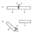
도 60은 제4 실시형태의 구체예 4의 세로 칸막이의 회전형태를 모식적으로 나타내는 도면이다.
도 61은 제4 실시형태의 구체예 4의 부착형태를 모식적으로 나타내는 도면 그 1이다.
도 62는 제4 실시형태의 구체예 4의 부착형태를 모식적으로 나타내는 도면 그 2이다.
도 63은 제4 실시형태의 구체예 5의 부착형태를 모식적으로 나타내는 도면이다.
도 64는 제4 실시형태의 구체예 6의 카메라 유닛의 구성을 모식적으로 나타내는 도면이다.BRIEF DESCRIPTION OF DRAWINGS FIG. 1 is a diagram showing an outline of the configuration of a home appliance network system using a refrigerator of the first embodiment. FIG.
2 is a diagram schematically showing a refrigerator of the first embodiment.
Fig. 3 is a diagram schematically showing an attachment form of the imaging camera according to the first embodiment. Fig.
4 is a diagram schematically showing a configuration of a refrigerator of the first embodiment.
Fig. 5 is a diagram schematically showing a state in the refrigerator compartment of the first embodiment. Fig.
6 is a diagram showing the flow of imaging processing by the refrigerator of the first embodiment.
7 is a diagram showing an example of an image taken by the imaging camera of the first embodiment.
8 is a diagram schematically showing a change in the dew condensation state of the imaging camera according to the first embodiment.
9 is a diagram showing an imaging sequence by the imaging camera of the first embodiment.
10 is a diagram showing the flow of terminal-side processing by the communication terminal of the first embodiment
Fig. 11 is a
Fig. 12 is a drawing 2 showing an example of an image display form in the communication terminal of the first embodiment. Fig.
Fig. 13 is a view schematically showing a configuration in which a camera device is installed in a refrigerator door pocket according to the second embodiment. Fig.
Fig. 14 is a view schematically showing a configuration in which a door pocket for a refrigerator according to the second embodiment is installed in a refrigerator. Fig.
15 is a diagram schematically showing the appearance of a camera device according to the second embodiment.
Fig. 16 is a diagram schematically showing an outer appearance of a camera device according to the second embodiment and an arrangement of parts inside the camera device.
17 is a view schematically showing a configuration in which the camera device of the second embodiment is installed in a door pocket for a refrigerator.
Fig. 18 is a diagram schematically showing a position where a refrigerator holder according to the second embodiment is installed. Fig.
Fig. 19 schematically shows a holder for a refrigerator according to the second embodiment. Fig.
Fig. 20 is a diagram schematically showing a form in which a holder for a refrigerator according to the second embodiment is attached. Fig.
21 is a diagram schematically showing an electrical configuration of a camera apparatus according to the second embodiment.
Fig. 22 is a diagram schematically showing the detection form of the detection unit of the camera apparatus according to the second embodiment. Fig.
23 is a diagram showing an example of the imaging timing of the camera apparatus according to the second embodiment
24 is a view showing an example of an image in an image picked up by the camera apparatus of the second embodiment
25 is a diagram showing an outline of the configuration of the home network system of the second embodiment.
26 is a side view (No. 1) showing a configuration example in a storage room of a refrigerator according to the third embodiment;
27 is a front view (No. 1) showing a configuration example in a storage room of a refrigerator according to the third embodiment;
28 is a plan view (No. 1) showing a configuration example in a storage room of a refrigerator according to the third embodiment;
29 is a longitudinal sectional view showing a configuration example in the concave portion according to the third embodiment.
30 is a cross-sectional view (No. 1) showing a configuration example in the concave portion according to the third embodiment.
31 is a plan view (No. 2) showing a configuration example in a storage room of a refrigerator according to the third embodiment;
32 is a plan view (No. 3) showing a configuration example in a storage room of a refrigerator according to the third embodiment;
33 is a cross-sectional view (No. 2) showing a configuration example in the concave portion according to the third embodiment.
34 is a cross-sectional view (No. 3) showing a configuration example in the concave portion according to the third embodiment.
35 is a cross-sectional view (No. 4) showing a configuration example in the concave portion according to the third embodiment.
36 is a plan view (No. 4) showing a configuration example in a storage room of a refrigerator according to the third embodiment;
37 is a front view (No. 2) showing a configuration example in a storage room of a refrigerator according to the third embodiment;
38 is a diagram showing a configuration example of a refrigerator according to the third embodiment.
39 is a plan view (No. 5) showing a configuration example in a storage room of a refrigerator according to the third embodiment;
40 is a diagram (No. 1) showing an example of the arrangement of an imaging camera and an LED for illumination according to the third embodiment.
41 is a drawing (No. 2) showing an example of the arrangement of an imaging camera and an LED for illumination according to the third embodiment.
42 is a side view (No. 2) showing a configuration example in the storage room of the refrigerator according to the third embodiment;
43 is a side view (No. 3) showing a configuration example in the storage room of the refrigerator according to the third embodiment;
44 is a side view (No. 4) showing a configuration example in a storage room of a refrigerator according to the third embodiment;
45 is a cross-sectional view (No. 5) showing a configuration example in the concave portion according to the third embodiment.
46 is a front view (No. 3) showing a configuration example in a storage room of a refrigerator according to the third embodiment;
47 is a front view (No. 4) showing a configuration example in a storage room of a refrigerator according to the third embodiment;
48 is a front view (No. 5) showing a configuration example in a storage room of a refrigerator according to the third embodiment;
Fig. 49 is a diagram schematically showing an attachment state of an imaging camera according to another embodiment. Fig.
50 is a diagram schematically showing a configuration of a refrigerator of another embodiment.
51 is a diagram showing an example of an image display mode in a communication terminal according to another embodiment;
52 is a view showing an example of an attaching portion according to another embodiment.
53 is a diagram schematically showing a refrigerator according to the fourth embodiment.
54 is a diagram schematically showing a configuration of a camera unit according to the fourth embodiment.
55 is a diagram schematically showing the lens unit of the fourth embodiment.
56 is a view schematically showing an attachment form of the first embodiment of the fourth embodiment; Fig.
Fig. 57 schematically shows the attachment form of the concrete example 2 of the fourth embodiment; Fig.
Fig. 58 schematically shows an installation form of the concrete example 3 of the fourth embodiment; Fig.
Fig. 59 is a diagram schematically showing an imaging result and display form according to the fourth embodiment. Fig.
Fig. 60 is a diagram schematically showing the rotation form of the vertical partition of the fourth example of the fourth embodiment. Fig.
61 schematically shows an attachment form of the fourth example of the fourth embodiment; Fig.
Fig. 62 schematically shows an attachment form of the fourth example of the fourth embodiment; Fig.
Fig. 63 is a diagram schematically showing an attachment form of the fifth example of the fourth embodiment. Fig.
Fig. 64 is a diagram schematically showing a configuration of a camera unit according to
이하, 복수의 실시형태에 의해 냉장고, 카메라 장치, 냉장고용 도어 포켓, 통신 단말, 가전 네트워크 시스템, 고내 화상 표시 프로그램에 대해서 설명한다. 또한, 각 실시형태에서 실질적으로 공통되는 부위는 공통되는 부호를 붙이고, 그 상세한 설명은 생략한다.Hereinafter, a refrigerator, a camera device, a door pocket for a refrigerator, a communication terminal, a home appliance network system, and a high-end image display program will be described with reference to a plurality of embodiments. In the embodiments, substantially common parts are denoted by the same reference numerals, and a detailed description thereof will be omitted.
(제1 실시형태)(First Embodiment)
이하, 제1 실시형태에 대해서, 도 1 내지 도 12를 참조하면서 설명한다.Hereinafter, a first embodiment will be described with reference to Figs. 1 to 12. Fig.
도 1에 도시한 바와 같이 본 실시형태의 냉장고(1)를 채용한 가전 네트워크 시스템(100)에서는 냉장고(1)는 라우터(101)를 통하여 외부의 통신회선(102)에 통신 가능하게 접속되어 있다. 이 라우터(101)는 소위 무선 액세스 포인트이며, 무선 통신 방식에서 냉장고(1)와 통신 가능하게 접속되어 있다. 이 냉장고(1)는 통신 회선(102)에 접속되어 있는 통신 단말(103) 및 서버(104)(모두 외부 장치에 상당함) 사이에서 각종 정보를 교환한다. 또한, 본 실시형태의 가전 네트워크 시스템(100)에서는 후술하는 바와 같이, 냉장고(1)의 고내를 촬상한 화상 정보는 서버(104)에서 기억되고, 통신 단말(103)은 서버(104)로부터 고내의 화상을 취득하는 구성으로 되어 있다. 여기에서 화상 정보란 고내의 화상을 나타내는 정보(데이터)이고, 예를 들면 비트 맵 형식이나 JPEG 형식 또는 MPEG 형식 등의 주지의 포맷의 화상 데이터(정지화상, 동화상), 화상 데이터를 압축이나 암호화 또는 제2 실시형태와 같이 화상 처리함으로써 변환한 데이터 등, 통신수단을 통한 송신이 가능하고 최종적으로 고내의 모습을 확인할 수 있는 것이면, 어떠한 형식의 데이터이어도 좋다. 또한, 본 실시형태에서는 통신 단말(103)로서 주택(105)의 외부에 휴대 가능한 이른바 스마트폰(고기능 휴대 전화)이나 태블릿형 퍼스널컴퓨터, 가전 네트워크 시스템(100)에 접속되어 있는 텔레비전 등을 상정하고 있다.1, in the household
냉장고(1)는 도 2에 도시한 바와 같이, 본체(2)의 상부부터 차례로, 식재료를 저장하기 위한 저장고인 냉장실(3), 야채실(4), 제빙실(5), 상부 냉동실(6) 및 하부 냉동실(7)이 설치되어 있다. 냉장실(3) 및 야채실(4)과, 제빙실(5) 및 상부 냉동실(6) 사이에는, 도시하지 않은 단열 칸막이벽에 의해 구획되어 있다. 냉장실(3)은 소위 좌우 여닫이식의 좌측 문(3a) 및 우측 문(3b)에 의해 개폐되고 야채실(4), 제빙실(5), 상부 냉동실(6) 및 하부 냉동실(7)은 인출식의 문(4a), 문(5a), 문(6a)및 문(7a)에 의해서 각각 개폐되도록 이루어져 있다.2, the
각 문에는 그 개폐 상태를 검지하기 위한 센서가 설치되어 있다(도 4 참조. 단지, 도 4에서는 좌측 문(3a)용 좌측 도어 센서(34), 우측 문(3b)용 우측 도어 센서(35)만 도시하고 있다). 또한, 도 2에 도시한 냉장고(1)의 구성은 하나의 예이며, 각 저장고의 배치 순서가 다르거나, 예를 들면 상부 냉동실(6)이 냉장 및 냉동을 전환 가능한 전환실인 바와 같은 구성이어도 좋다.4, a
냉장실(3)의 좌측 문(3a)에는 상단부터 차례로 도어 포켓(8a), 도어 포켓(9a), 도어 포켓(10a)이 설치되어 있고, 우측 문(3b)에는 상단부터 차례로 도어 포켓(8b), 도어 포켓(9b), 도어 포켓(10b)이 설치되어 있다. 또한, 냉장실(3)내에는 예를 들면 유리 등의 투명성 재료로 형성되어 있는 복수의 선반판(11)이 설치되어 있고, 또한 최하단에는 예를 들면 달걀실이나 칠드실과 같은 특정 목적실(12)이 배치되어 있다. 또한, 냉장실(3)의 상부에는 조명 수단으로서의 천정 조명(13)이 설치되어 있다. 또한, 냉장실(3) 내에는 측면에 설치되어 있는 측면 조명(36)(도 4참조)도 설치되어 있다. 이 중, 천정 조명(13)은 고내의 상부측, 측면 조명(36)은 고내의 중앙부나 하부 등, 고내의 특정 위치를 비추기 위해 설치되어 있다.
냉장실(3)의 좌측 문(3a) 및 우측 문(3b)은 그 전면이 절연성(絶緣性) 유리 재료로 형성된 유리판(3b1)으로 덮여 있고 그 내부에는 단열재인 우레탄이 충전제로서 충전되어 있으며, 그 내측에 대해서는 주지하는 것처럼, 비금속의 수지제의 내판(14) 및 세로판(15)을 구비하고 있다. 즉, 좌측 문(3a) 및 우측 문(3b)의 전방면측은 전파를 투과시키는 비금속제 재료인 유리판(3b1)으로 구성되어 있다. 상기한 도어 포켓(8~10)은 이 내판(14)에 설치되어 있다. 세로판(15)에는 상하 방향에서의 중앙 부근이며 좌우 방향에서의 우측 문(3b)의 개방단부측(구체적으로는, 후술하는 촬상 카메라(18)가 설치되어 있는 부근)에 오목부(16)가 형성되어 있다. 이 오목부(16)는 후술하는 바와 같이, 촬상 카메라(18)의 시야를 방해하지 않도록 설치되어 있다. 또한, 좌측 문(3a)에는 우측 문(3b)과의 간극을 메우기 위한 회전식의 세로 칸막이(17)가 설치되어 있다. 또한, 야채실(4)의 문(4) 등도 우측 문(3b)과 동일하게 그 전방면이 유리판으로 덮여 있고, 내부에는 우레탄이 단열재로서 충전되어 있는 구성으로 되어 있다.The
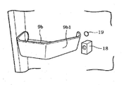
우측 문(3b)의 내판(14)(세로 칸막이를 갖고 있지 않은 문)에는, 도 2에 도시한 바와 같이, 촬상 카메라(18) 및 촬상 조명(19)이 설치되어 있다. 즉, 본 실시형태에서는 내판(14)이 피부착부에 상당한다. 촬상 카메라(18)는 CCD 또는 CMOS등의 촬상 소자를 갖고 있고, 고내의 화상을 문측에서 촬상한다. 이 촬상 카메라(18)는 대체로 120도 정도의 시야각을 갖는 광각 렌즈를 구비하고 있다. 그리고, 촬상 카메라(18)는 중간단의 도어 포켓(9b)에 인접한 위치이며, 도어 포켓(9b)보다 좌측 문(3a)측이 되는 위치에 설치되어 있다. 즉, 촬상 카메라(18)는 냉장실(3)의 상하 방향의 중앙 부근, 또한 냉장실(3)의 좌우 방향의 중앙 부근에 설치되어 있다. 이 때문에, 우측 문(3b)이 폐쇄된 상태에서 촬상 카메라(18)는 그 시야가, 후술하는 도 7에 도시한 바와 같이 냉장실(3)의 고내의 거의 전역, 또한 도어 포켓(8~10)의 적어도 일부를 촬상 가능해져 있다. 또한, 비교예로서 일반적인 Web 카메라의 경우, 그 시야각은 대체로 55도 정도이다.2, an
촬상 카메라(18)에 인접하는 도어 포켓(9b)은 도 3에 도시한 바와 같이 촬상 카메라(18)측이 비스듬히 형성되어 있다. 즉, 일반적으로는 수용부가 사각형(장방형)으로 형성되는 도어 포켓(9b)에는, 광각 렌즈를 채용하고 있는 촬상 카메라(18)의 시야를 확보하기 위해서, 절개부(9b1)가 형성되어 있다. 또한, 도 3 등은 촬상 카메라(18)를 모식적으로 나타내는 것이고, 촬상 카메라(18)의 실제 크기나 형상과는 다르다. 또한, 촬상 카메라(18)는 본 실시형태에서는 냉장고(1)에 부착된 구조로 되어 있지만, 후술하는 제2 실시형태와 같이 냉장고(1)로부터 착탈 가능(예를 들어, 냉장고(1)의 구입 후, 옵션 장치로서 부착하는 등)하게 해도 좋다.The
촬상 조명(19)은 예를 들면 촬상 카메라(18)의 상부측에 설치되어 있다. 즉, 촬상 조명(19)은 그 조사 방향이 촬상 카메라(18)의 시야와 동일한 방향이 되도록 배치되어 있고, 조사되는 광이 촬상 카메라(18)에 직접 들어가지 않는 위치(대향 위치 밖의 위치), 즉 촬상 카메라(18)에 있어 역광이 되기 힘든 위치 또는 역광이 되지 않는 위치에 배치되어 있다. 촬상 카메라(18)는 특허청구범위에 기재된 촬상 수단을 구성하고, 촬상 조명(19)은 특허청구범위에 기재한 조명 수단을 구성한다.The
이 냉장고(1)는 도 4에 도시한 바와 같이 주제어부(30)에 의해 제어되어 있다. 주제어부(30)는 CPU(30a), ROM(30b) 및 RAM(30c) 등을 갖는 마이크로 컴퓨터로 구성되어 있으며, 예를 들면 ROM(30b)등에 기억되어 있는 컴퓨터 프로그램을 실행함으로써 냉장고(1) 전체를 제어한다.The
주제어부(30)는 주지의 냉동 사이클 등으로 구성되어 있는 냉장용 냉각 기구(31)와 냉동용 냉각 기구(32), 냉장고(1)에 대한 설정 조작 등을 입력하기 위한 조작 패널(33), 좌측 도어 센서(34), 우측 도어 센서(35), 천정 조명(13) 및 측면 조명 등에 접속되어 있다. 또한, 냉장고(1)는 냉장실(3)이나 하부 냉동실(7) 등의 온도를 검출하는 도시하지 않은 고내 센서 등도 구비하고 있다.The
조작 패널(33)은 표시기(33a), 스위치류(33b) 및 고외 센서(33c)를 갖고 있다. 표시기(33a)는 냉장고(1)의 운전 상태 등의 각종 정보를 표시한다. 스위치류(33b)는 냉장고(1)에 대한 사용자의 설정 조작 등이 입력된다. 이 스위치류(33b)에는 사용자가 외출할 때 냉장고(1)의 운전 상태를 전환하기 위한 외출 스위치도 포함되어 있다. 이 외출 스위치는 예를 들어, 「절전」,「외출」 등이 설정되어 있고, 어느 것인가 선택되면 해당하는 전력 절감 모드로 이행한다. 즉, 사용자가 외출하면 냉장고(1)를 사용하지 않는 상태가 되기 때문에, 냉장고(1)는 전력 절감 모드로 이행하여 소비 전력을 삭감한다.The
예를 들면,「절전」이 선택되면 냉장고(1)는 식재료의 저장 환경에 영향이 나타나지 않는 범위에서 고내온도를 조절하고, 또한 결로 방지용 히터의 운전 상태를 제어함으로써, 통상시보다 약 10% 정도의 소비 전력을 삭감하는 모드로 이행한다. 또는,「외출」이 선택되면 냉장고(1)는 자동 제빙의 횟수를 삭감하고, 통상시에 비하여 소비전력을 삭감하는 전력 절감 모드로 이행한다. 보다 구체적으로는 냉장고(1)는 자동 제빙의 횟수를 예를 들면 8시간에 1회로 함으로써, 통상 운전시에 비하여 약 20%정도의 소비 전력을 감소시키고 있다.For example, when "power save" is selected, the
또한, 본 실시형태에서는 냉장고(1)에 미리 설치되어 있는 「절전」이나 「외출」용 스위치를 외출 스위치로서 겸용하고 있지만, 외출하는 취지를 설정하기 위한 전용의 스위치를 설치해도 좋다.In the present embodiment, the "power saving" or "outgoing" switch provided in advance in the
고외 센서(33c)는 온도 센서와 습도 센서에 의해 형성되어 있고, 고외의 환경을 취득한다. 고외 센서(33c)는 특허청구범위에 기재한 고외 환경 취득 수단을 구성한다.The high-
주제어부(30)는 고내 센서에서 취득한 고내의 환경 및 고외 센서(33c)에서 취득한 고외의 환경에 기초하여, 또한 조작 패널(33)로부터의 설정에 기초하여, 냉장고(1)의 운전 상태를 제어한다. 또한, 주제어부(30)는 좌측 도어 센서(34)나 우측 도어 센서(35)로부터 문의 개폐 상태를 취득한다. 이 주제어부(30)는 제어부(50)와 통신 가능하게 접속되어 있고, 문의 개폐 상태를 제어부(50)에 송신하거나 천정 조명(13)이나 측면 조명(36)의 점등 지시를 제어부(50)로부터 수신할 수 있다.The
제어부(50)는 CPU(50a), ROM(50b), RAM(50c) 및 시각을 취득하기 위한 실시간 클럭(이하, RTC(50d)라고 함)을 갖는 마이크로 컴퓨터로 구성되어 있다. 이 제어부(50)는 촬상 카메라(18), 촬상 조명(19), 렌즈 히터(51) 및 통신부(52)에 접속되어 있다.The
제어부(50)는 예를 들면 ROM(50b) 등에 기억되어 있는 컴퓨터 프로그램을 실행함으로써 촬상 카메라(18)에 의해 고내를 촬상하는 타이밍 및 촬상 카메라(18)에서 고내를 촬상하기 위한 촬상 환경을 제어한다. 구체적으로는 주제어부(30)로부터 수신한 문의 개폐 상태 등에 기초하여 촬상하는 타이밍을 제어하고, 또한 촬상 환경 즉 촬상을 위해 필요한 광원인 천정 조명(13)이나 촬상 조명(19)등의 점등 상태를 제어한다. 제어부(50)는 특허청구의 범위에 기재한 제어 수단을 구성한다.The
여기서 촬상하는 타이밍에 대해서 설명한다.Here, the timing of imaging will be described.
고내를 촬상하는 경우 촬상 카메라(18)를 구동하고, 또한 촬상 조명(19)등을 점등할 필요가 있다. 즉, 고내를 촬상하기 위해서는 전력을 소비할 필요가 있다. 이 때문에 항상 촬상 가능한 상태가 되어 있으면, 불필요한 전력을 소비하게 된다. 그래서, 냉장고(1)에서는 고내를 촬상하는 타이밍을 제어함으로써, 또한 그 타이밍에 맞추어 필요할 때에만 촬상 환경(즉, 촬상 조명(19)등의 점등)을 제어함으로써 소비 전력의 삭감을 도모하고 있다.It is necessary to drive the
고내를 촬상하는 타이밍은 예를 들면 이하의 촬상 조건 1~5와 같은 조건이 미리 설정되어 있고, 제어부(50)는 어느 촬상 조건이 충족되면 고내를 촬상할 타이밍이 되었다고 판정한다.For example, the same conditions as in the following
- 촬상 조건 1: 냉장실(3)의 어느 문이 일단 개방된 후에 폐쇄된 타이밍. 즉, 고내의 식재료의 저장 상황이 변화되었을 가능성이 있는 타이밍.- Imaging condition 1: timing at which any door of the refrigerating chamber (3) is once closed after being opened. That is, the timing at which the storage condition of the ingredients in the poultry may have changed.
- 촬상 조건 2: 냉장실(3)의 어느 문이 개방된 타이밍. 즉, 고내 식재료의 저장 상황이 변화될 가능성이 있는 타이밍.- Imaging condition 2: timing at which any door of the refrigerating chamber (3) is opened. That is, there is a possibility that the storage condition of the high-fat ingredients is likely to change.
- 촬상 조건 3: 통신 단말 등의 외부 장치로부터 지령을 접수한 타이밍.- Imaging condition 3: Timing of receiving a command from an external device such as a communication terminal.
- 촬상 조건 4: 외출 스위치가 조작된 경우. 외출 스위치가 조작된 타이밍에서 촬상해도 좋고 외출 스위치가 조작되고 나서 소정의 대기 시간이 경과된 타이밍에서 촬상해도 좋다. 또한, 어느 타이밍을 채용할지는 미리 설정해 두면 좋다.- Imaging condition 4: When the outgoing switch is operated. It may be sensed at a timing at which the outgoing switch is operated or at a timing when a predetermined waiting time has elapsed since the outgoing switch was operated. In addition, it is preferable to set in advance which timing to adopt.
- 촬상 조건 5: 일단 개방된 문이 폐쇄된 후이며, 소정 기간이 경과된 타이밍(본 실시형태에서는 촬상 카메라(18)의 광각 렌즈의 결로가 제거될 때까지 요하는 것으로 상정되는 지연 촬상 시간이 경과한 타이밍을 채용하고 있다). 즉, 광각 렌즈의 결로가 제거된 타이밍. 또한, 지연 촬상 시간은 미리 고정값을 설정해도 좋고 고외 센서(33c)에서 취득한 고외의 습도나 온도에 기초하여 그때마다 설정해도 좋다.- Imaging condition 5: A delayed imaging time assumed to be required until the condensation of the wide-angle lens of the
- 촬상 조건 6: 일단 개방된 문이 폐쇄된 후이며, 촬상 카메라(18)의 광각 렌즈의 결로가 렌즈 히터(51)에 의해 제거된 타이밍. 즉, 광각 렌즈의 결로가 제거된 타이밍.- Imaging condition 6: The timing at which the door once opened is closed, and the condensation of the wide-angle lens of the
또한, 촬상 조건으로서는 상기한 것 중 어느 것인가를 채용해도 좋고, 상반되지 않는 조건이면 복수를 조합하여 채용해도 좋다. 본 실시형태에서는 판정 조건 1, 판정 조건 3, 판정 조건 4, 판정 조건 5를 채용하고 있다.As the imaging conditions, any of the above-described conditions may be employed, or a plurality of conditions may be employed in combination if the conditions are not contradictory. In the present embodiment,
통신부(52)는 소위 무선 LAN이나 Bluetooth(등록 상표) 등의 무선 통신 방식에 의해 라우터(101)와의 사이에서 통신을 실시한다. 구체적으로는 통신부(52)는, 촬상된 고내의 화상을 라우터(101) 및 통신 회선(102)을 통하여 서버(104)에 업로드된다. 또한, 통신부(52)는 유선 통신 방식이어도 좋다.The
렌즈 히터(51)는 촬상 카메라(18)의 광각 렌즈를 가열함으로써 후술하는 도 8에 도시한 바와 같이 렌즈면의 결로의 제거를 실시한다(제거 수단에 상당한다). 이 렌즈 히터(51)는 전열선 등의 통전에 의해 발열하는 발열 부재에 의해 구성해도 좋고, 제어부(50)를 구성하는 마이크로 컴퓨터의 발열 또는 그 발열을 전하는 전열부재에 의해 구성해도 좋다. 이 경우 마이크로 컴퓨터의 발열을 이용하기 위해, 마이크로 컴퓨터를 전력 절감 모드로부터 복귀시키면 좋다. 또한, 제거 수단으로서 팬 등을 채용해도 좋다. 구체적으로는 팬을 구동하여 렌즈면에 냉기를 송풍하고, 결로가 제거될 것으로 예상되는 소정 시간이 경과한 후에 촬상하면 좋다. 어쨌든, 렌즈면의 결로를 제거할 수 있으면 어떠한 구성이어도 좋다.The
통신 단말(103)는 서버(104)에 액세스함으로써 서버(104)에 기억되어 있는 고내의 화상을 취득하여 표시한다. 즉, 본 실시형태에서는 통신 단말(103)은 냉장고(1)로부터 직접 화상을 취득하는 것이 아니라, 일단 서버(104)에 기억된 화상을 취득한다.The
서버(104)는 이른바 컴퓨터 시스템으로 구성되어 있고, 업로드된 화상을 시계열, 또한 복수매 기억한다. 또한, 서버(104)는 통신 단말과 냉장고(1)를 대응지어 둠으로써, 화상을 취득하는 통신 단말에 대해서 해당하는 냉장고(1)의 화상을 제공한다.The
다음에 상기한 구성의 작용에 대해서 설명한다. 또한, 이하에 설명하는 처리는 주제어부(30) 및 제어부(50)가 협동하여 실시하고 있는 처리이지만, 설명의 간략화를 위해 냉장고(1)를 주체로 하여 설명한다.Next, the operation of the above-described configuration will be described. The processing described below is performed by the
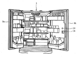
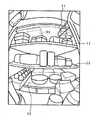
냉장고(1)의 냉장실(3)에는, 도 5에 도시한 바와 같이 각종의 식재료가 저장되어 있다. 냉장고(1)는 도 6에 도시한 촬상 처리를 실행하고 있고, 촬상 카메라(18)에서 고내를 촬상하기 위한 촬상 조건이 충족되었는지 여부를 판정하고 있으며(A1), 상술한 판정 조건 중 하나가 충족됐다고 판정하면(A1:예), 즉 촬상할 타이밍이 되었다고 판정하면 조명(촬상 조명(19))을 점등하고(A2), 고내를 촬상한다(A3). 이에 의해, 도 7과 같은 고내의 화상이 촬상된다.In the
도 7에서는 상기한 바와 같이 광각 렌즈에서 고내를 촬상하고 있는 점에서, 냉장실(3) 내의 거의 전체가 촬상되고 있다. 즉, 각각의 선반판(11)에 얹혀 있는 각종 식재료와, 도어 포켓에 수납되어 있는 각종 식재료가 시인 가능하게 촬상되고 있다. 또한, 선반판(11)이 투명성 재료로 형성되어 있는 점에서, 예를 들면 최상단의 선반판(11)에 얹혀 있는 식재료(S1)에 대해서도 선반판(11)을 투과하여 시인 가능하게 촬상되고 있다.7, substantially all of the inside of the refrigerating
또한, 촬상 조명(19)을 점등함으로써 촬상하고 있는 점에서, 역광이 되지 않고, 이곳의 식재료가 시인 가능하게 촬상되고 있다. 또한, 도시는 생략하지만, 비교예로서 천정 조명(13)을 점등한 상태에서 고내를 촬상한 경우, 천정 조명(13)으로부터의 빛이 역광이 되어, 식재료(S1)나 2단째의 선반판(11)에 얹혀 있는 식재료는 시인이 곤란한 상태로 촬상된다. 즉, 냉장고(1)는 촬상 카메라(18)에 대해서 역광이 되지 않는 촬상 조명(19)을 점등함으로써 고내를 시인 가능하게 촬상하기 위한 촬상 환경을 정비하고 있다.Further, since the
그리고 냉장고(1)는, 촬상한 화상 정보를 서버(104)로 송신한다(A4). 이때, 촬상한 시각도 동시에 서버(104)에 송신된다. 이에 의해, 서버(104)에는 고내의 화상이 시계열로, 또한 복수매 기억(축적)된다.Then, the
그런데, 냉장실(3)의 문을 개방한 경우, 우측 문(3b)의 내판(14)에 설치되어 있는 촬상 카메라(18)는 광각 렌즈째 고외의 환경에 노출된다. 이는 우측 문(3b)이 개방된 경우 뿐만 아니라, 좌측 문(3a)이 개방된 경우도 동일하다. 이 때문에, 문이 폐쇄된 직후에서는 고외의 환경에도 따르지만, 도 8(a)에 도시한 바와 같이 렌즈면이 결로되어 흐려질 가능성이 있다. 또한, 도 8에서는 렌즈면에 생긴 결로를 해칭으로 모식적으로 도시하고 있고, 도 8(a)는 결로된 상태(문을 폐쇄한 직후)를 나타내며, 도 8(b)은 서서히 결로가 제거된 상태(문을 폐쇄한 후, 얼마동안 시간이 경과한 상태)를 나타내고, 도 8(c)는 결로가 제거된 상태(지연 촬상 시간이 경과한 상태)를 나타내고 있다.When the door of the refrigerating
이와 같이, 문을 폐쇄한 직후에 고내를 촬상하면, 결로에 의해 시인이 곤란해질 우려가 있다. 그래서, 냉장고(1)는 상술한 판정 조건 5를 채용하고, 일단 개방된 문이 폐쇄된 후에 지연 촬상 시간이 경과한 타이밍에서 더욱 고내를 촬상한다. 즉, 판정 조건 5가 성립한 경우(A1:예), 조명을 점등하고(A2), 고내를 촬상하여(A3), 촬상한 화상 정보를 서버(104)에 송신한다(A4).As described above, if the inside of the room is imaged immediately after the door is closed, there is a fear that visibility becomes difficult due to condensation. Thus, the
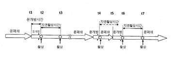
보다 상세하게는 도 9와 같이, 문이 폐쇄되어 있고 시각 t1에서 문이 개방되어 시각 t2에서 폐쇄되었고 하면, 시각 t2에서 우선 화상을 촬상하고 그 후 지연 촬상 시간이 경과한 시각 t3에서 다시 화상을 촬상한다. 이 경우 시간 t4에서 문이 폐쇄되고 촬상한 후, 지연 촬상 시간이 경과하기 전의 시각 t5에서 다시 문이 개방된 경우에는, 문이 폐쇄된 시각 t6에서 일단 촬상한 후, 지연 촬상 시간이 경과한 시각 t7에서 다시 촬상된다. 이에 의해, 광각 렌즈의 결로가 제거된 상태, 즉 고내를 시인 가능한 화상을 촬상하는 것이 가능해진다.More specifically, as shown in FIG. 9, when the door is closed and the door is opened at time t1 and closed at time t2, a priority image is taken at time t2, and again at time t3 when the delayed imaging time has elapsed . In this case, when the door is closed at the time t4, and the door is opened again at the time t5 before the delay imaging time elapses after the image is taken, the time at which the delay imaging time elapses after imaging is performed once at the time t6 when the door is closed the image is picked up again at t7. This makes it possible to capture an image in which the condensation of the wide-angle lens is removed, that is, an image in which the inside of the wide-angle lens can be seen.
서버(104)에 화상 정보를 송신하면 제어부(50)는 대기 상태가 된다. 이 대기 상태에서는 제어부(50)를 소위 슬립 모드 등의 전력 절감 모드(예를 들어 제빙 동작을 정지하는 등)로 이행해도 좋고, 촬상 카메라(18) 등도 포함하는 제어부(50)측으로의 통전을 차단하여 소비 전력을 제로로 해도 좋다. 그리고, 예를 들면 도어 센서에 의해 문의 개방 등을 검지했을 때에 주제어부(30)로부터 제어부(50)에 대해서 통상 모드로 이행하는 지령을 출력하거나 통전을 개시하면 좋다. 이에 의해, 냉장고(1)의 총소비 전력을 삭감하는 것이 가능해진다.When the image information is transmitted to the
그런데, 서버(104)에 기억되어 있는 화상은, 통신 단말(103)에서 표시할 수 있다. 통신 단말(103)은 화상을 취득하기 위한 어플리케이션이 기동되면 도 10에 도시한 단말측 처리(고내 화상 표시 프로그램에 상당함)를 실행하여, 서버(104)로부터 최신 화상(또는 화상 정보)을 취득한다(B1). 이에 의해, 통신 단말(103)의 화면에는, 도 11에 도시한 바와 같은 고내의 화상이 촬상 시각과 함께 표시된다. 또한, 통신 단말(103)에는 화면에 대응한 터치 패널이 설치되어 있다.By the way, the image stored in the
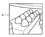
이 화면에는 현재의 화상을 취득하기 위한 버튼 M1, 어플리케이션을 종료하기 위한 버튼 M2, 표시 중의 화상보다도 과거의 화상을 표시하기 위한 버튼 M3, 표시 중의 화상보다 새로운 화상을 표시하기 위한 버튼 M4 등이 설치되어 있다. 또한, 통신 단말은 원하는 영역을 확대하여 표시하는 것도 가능하고, 도 11에 도시한 영역 R을 확대하여 도 12에 도시한 바와 같이 표시함으로써, 예를 들어 달걀이 몇 개 남아 있는지를 사용자가 파악할 수 있다.In this screen, a button M1 for acquiring the current image, a button M2 for terminating the application, a button M3 for displaying the past image than the image during display, a button M4 for displaying a new image than the displayed image are installed . Further, the communication terminal can enlarge and display a desired area. By enlarging the area R shown in Fig. 11 and displaying it as shown in Fig. 12, for example, the user can grasp how many eggs remain have.
또한, 통신 단말(103)은 사용자가 버튼 M1을 터치 조작하면, 즉, 최신의 화상을 취득하기 위한 조작이 입력되면(B2: 예), 냉장고(1)에 대해서 고내를 촬상하기 위한 지령을 송신하고(B3), 서버(104)로부터 화상을 취득하고(B4), 취득한 화상을 표시한다(B5). 또한, 단계 B3 후 냉장고(1)측에서는 도 6에서 촬상 조건 3이 성립한 점에서 고내를 촬상하고, 촬상한 화상 정보가 서버(104)로 송신되고 있다.When an operation for acquiring the latest image is input (B2: Yes), the
이와 같이, 가전 네트워크 시스템(100)에서는 냉장고(1)가 고내를 촬상한 화상 정보를 서버(104)에 송신하고, 서버(104)가 그 화상을 기억하며, 통신 단말(103)가 서버(104)로부터 화상을 취득하여 표시함으로써, 고내의 모습을 외출지 등 원격지에서 확인 가능하게 하고 있다.As described above, in the household
이상 설명한 본 실시형태에 따르면 다음과 같은 효과를 갖는다.According to the present embodiment described above, the following effects are obtained.
냉장고(1)는 식품을 저장하는 냉장실(3) 등의 저장고의 고내를 촬상하는 촬상 카메라(18)와, 촬상 카메라(18)에서 촬상한 고내의 화상 정보를 외부 장치에 송신하기 위한 통신부(52)을 갖고 있으므로, 예를 들면 통신 단말(103)과 같은 외부 장치에서 고내의 화상을 취득할 수 있다. 이에 의해, 외출지 등 원격지에서 쉽게 냉장고 고내를 확인할 수 있다.The
이 경우, 본 실시형태에서는 고내의 화상을 일단 서버(104)에 기억시키고 있으므로. 냉장고(1)측에는 화상을 기억하기 위한 기억 수단을 설치할 필요가 없어, 제조 비용의 증가를 억제할 수 있다. 또한, 냉장고(1)에 기억부를 설치하여 냉장고(1)측에서 화상을 기억하는 구성으로 해도 좋다.In this case, in the present embodiment, the
또한, 제어부(50)는 서버(104)에 화상 정보를 송신한 후에는 대기 상태가 된다. 즉, 촬상시 이외에는 제어부(50)측(촬상 카메라(18)등도 포함)의 소비 전력은 삭감된 상태 또는 제로가 된다. 이에 의해, 냉장고(1)의 총소비 전력을 삭감하는 것이 가능해진다.Further, after the
제어부(50)는 촬상 카메라(18)에 의해 고내를 촬상하는 타이밍을 제어하고, 또한 그 타이밍에 맞추어 고내를 촬상하기 위한 조명의 점등 등의 촬상 환경을 제어한다. 고내를 촬상하기 위해서는 광원이 필요하고, 항상 촬상 가능한 상태가 되고 있으면 불필요한 전력을 소비하게 되지만, 고내를 촬상하는 타이밍에 맞추어 촬상할 때만 촬상 조명(19) 등을 점등하도록 촬상 환경을 제어함으로써, 불필요한 전력 소비를 삭감할 수 있다. 또한, 광원이 없는 상태에서도 촬상 가능한 암시 카메라(예를 들어 적외선 카메라) 등을 채용하여 조명이 점등하지 않은 상태에서 촬상해도 좋다. 또한, 조명을 상시 점등시켜 두어도 좋다.The
냉장고(1)는 냉장실(3)의 문이 폐쇄된 후의 타이밍에서 촬상 카메라(18)에 의해 고내를 촬상한다. 냉장고의 저장 상황이 바뀌지 않았음에도 불구하고 촬상하면, 불필요한 화상이 축적될 뿐만 아니라, 전력 소비 증가도 초래하게 된다. 그 때문에, 본 실시형태에서는 냉장고는 문이 일단 개방되고 그 문이 폐쇄된 후의 타이밍에서 고내를 촬상한다. 이에 의해, 고내 식재료의 저장 상태가 변화될 가능성이 있는 상태(문이 일단 개방된 상태)에서 저장 상태가 확정된 상태(문이 폐쇄된 후의 상태)에서 고내를 촬상함으로써, 불필요한 촬상을 억제하고 전력 소비가 증가되는 것을 억제할 수 있다.The refrigerator (1) picks up the inside of the room by the imaging camera (18) at a timing after the door of the refrigerating chamber (3) is closed. Even if the storage condition of the refrigerator is not changed, if images are taken, not only unnecessary images are accumulated but also power consumption is increased. Therefore, in the present embodiment, the refrigerator captures the interior of the room at the timing after the door is once opened and the door is closed. Thus, by capturing the inside of the room in a state in which the storage state is determined (the state after the door is closed) in a state in which the storage state of the in-house ingredients is likely to change (door is once opened), unnecessary imaging is suppressed, Increase in consumption can be suppressed.
또한, 냉장고(1)는 문이 폐쇄된 후이며, 촬상 카메라(18)의 광각 렌즈의 결로가 제거될 때까지 요하는 지연 촬상 시간이 경과한 타이밍에서 고내를 촬상한다. 예를 들면, 여름처럼 기온이 높은 경우나 습도가 높은 경우, 문이 개방되어 고외의 환경에 노출된 촬상 카메라는, 문이 폐쇄되면 냉장실(3)내의 온도가 낮기 때문에 렌즈면에 결로가 생길 가능성이 있다. 그래서, 그 결로가 제거된다고 상정되는 지연 촬상 시간이 경과한 타이밍에서 다시 고내를 촬상함으로써, 렌즈면에 흐려짐이 없는 명료한 화상을 촬상할 수 있다. 따라서, 고내의 모습을 보다 확실하게 파악할 수 있다.Further, the
이 경우, 지연 촬상 시간은 고외 센서(33c)에 의해 취득한 온도나 습도 등의 고외의 환경에 기초하여 설정해도 좋다. 이에 의해, 온도나 습도가 낮은 경우 등에는 결로가 생기지 않는다(또는 적다)고 상정되므로, 지연 촬상 시간을 짧게 할 수 있어 소비 전력을 삭감할 수 있다. 구체적으로는 예를 들면 지연 촬상 시간이 경과할 때까지 제어부(50)가 대기하는 구성의 경우, 대기 시간이 짧아짐으로써 그만큼의 소비 전력을 삭감할 수 있다.In this case, the delayed imaging time may be set based on the high-temperature environment such as the temperature and humidity acquired by the high-
또한, 촬상 카메라(18)의 광각 렌즈의 결로를 제거하는 경우, 렌즈 히터(51)와 같은 제거수단을 사용해도 좋다. 이 경우 냉장고(1)는 렌즈 히터(51)에 의해 렌즈면의 결로를 제거한 후의 타이밍에서 고내를 촬상하게 된다. 이 렌즈 히터(51)를 이용함으로써, 지연 촬상 시간을 더 짧게 할 수 있으므로, 소비 전력을 삭감할 수 있다. 이 경우, 렌즈 히터(51)를 제어부(50)의 자기 발열을 전하는 전열부재로 구성하면, 전력을 가외로 소비하지 않고 렌즈면의 결로를 제거할 수 있다. 또한, 제거 수단으로서 팬을 채용한 경우도 지연 촬상 시간이 짧아짐으로써 소비 전력을 삭감할 수 있다.Further, when condensation of the wide angle lens of the
냉장고(1)는 예를 들면 통신 단말(103)로부터 고내를 촬상하기 위한 지령을 접수한 타이밍에서 고내를 촬상한다. 예를 들면, 사용자가 외출 중이고 그 부재중에 가족이 냉장고(1)에서 식재료를 꺼내는 등에 의한 저장 상황이 변화될 가능성이 있지만, 사용자의 지령에 의해 그 시점에서의 화상을 촬상함으로써, 최신 즉 현 시점에서 냉장고(1)의 고내의 모습을 파악할 수 있다.The
냉장고(1)는 외출 스위치가 조작된 경우에 고내를 촬상하므로, 외출 후에 냉장고(1) 내의 모습을 확인하고 싶은 상황에 대응할 수 있다. 이 경우 예를 들면 혼자사는 사용자가 외출할 경우, 냉장고(1)의 저장 상황은 사용자가 외출한 시점부터 변화되지 않는다고 생각되므로, 외출 스위치가 조작된 경우에 촬상한 화상을 최신의 고내의 화상으로서 취급할 수 있다.Since the
또한, 실시형태에서는 채용하지 않았지만, 촬상 조건 2를 채용하여 고내 식재료의 저장 상황이 변화될 가능성이 있는 타이밍에서 촬상함으로써, 최신에 가까운 고내의 화상을 취득할 수 있다. 이 경우, 우측 문(3b)의 개방 중에는 촬상 카메라(18)의 시야가 흔들릴 가능성이 있기는 하지만, 예를 들면 우측 문(3b)이 개방되는 순간에 촬상함으로써 그 흔들림을 감소시킬 수 있고, 또한 문이 개방되면 고내 조명이 점등하므로, 조도를 확보할 수 있다.Though not employed in the embodiment, it is possible to acquire an image in a state close to the latest by taking images at a timing at which the storage condition of the in-vivo material is likely to be changed by employing the image pickup condition 2. In this case, although there is a possibility that the visual field of the
냉장고(1)는 촬상 카메라(18)에서 고내를 촬상할 때 고내를 비추기 위한 촬상 조명(19)을 점등하고 촬상 환경을 제어(정비)한다. 이에 의해, 문이 폐쇄된 상태이어도 광원을 확보할 수 있어, 고내를 시인 가능하게 촬상할 수 있다.The refrigerator (1) illuminates the imaging illumination (19) for illuminating the inside of the room when imaging the inside of the room by the imaging camera (18) and controls the imaging environment. Thereby, even if the door is closed, the light source can be secured, and imaging of the interior can be made visible.
냉장고(1)는 천정 조명(13)이나 촬상 조명(19) 또는 측면 조명(36)과 같이 고내에 복수 설치되어 있는 조명 수단 중 특정 위치(이 경우는 특히 촬상 위치)를 비추기 위한 촬상 조명(19)을 점등한다. 촬상 카메라(18)에서 촬상하는 경우 고내에 설치되어 있는 조명 수단과의 위치 관계에 따라서는 조명이 직접 시야에 들어가역광이 될 가능성이 있지만, 조명 수단의 전체를 점등하는 것이 아니라, 예를 들면 촬상 조명(19)처럼 촬상할 때 역광이 되지 않는 위치 등의 특정 위치를 비추기 위한 조명 수단을 점등함으로써 화상을 보다 선명하게 촬상할 수 있다. 구체적으로는 예를 들면 촬상 카메라(18)와 대향하는 배면측에 조명 수단이 설치되어 있는 경우는 적어도 가장 역광이 되는 조명 수단을 소등하고 다른 조명 수단(천정 조명(13)등)등을 이용하는 것 등이 생각된다.The
촬상 조명(19)은 촬상 카메라(18)의 대향 위치 밖이며, 또한 촬상 카메라(18)의 시야와 동일한 방향을 비추도록 설치되어 있으므로, 촬상 조명(19)으로부터의 광이 역광이 되지 않고 고내의 모습을 상세하게 파악할 수 있다.Since the
고내를 촬상할 때는 촬상 카메라(18)의 시야를 확보하기 위해서 어느 정도의 거리가 필요해지지만, 촬상 카메라(18)를 냉장실(3)의 문에 설치하고 있으므로, 촬상 카메라(18)와, 선반판(11) 등에 수납되어 있는 식재료와의 거리를 확보할 수 있어 시야를 크게 할 수 있다.The
촬상 카메라(18)를 우측 문(3b)의 내판(14)에 설치하고 있으므로, 문이 폐쇄된 상태이어도 고내를 촬상할 수 있다.Since the
이 경우, 촬상 카메라(18)를 냉장실(3)의 상하 방향의 중앙 부근, 또한 냉장실(3)의 좌우 방향의 중앙 부근에 설치하고, 또한 광각 렌즈를 채용하고 있으므로, 촬상 카메라(18)는 냉장실(3)의 고내의 거의 전역을 고내의 중앙부 부근으로부터 화상(즉, 사용자가 통상 냉장고(1)내를 보고 있는 상태와 조사 상태에서의 화상)으로서 촬상할 수 있다. 이때 선반판(11)을 투명성 재료로 형성하는 점에서, 예를 들면 최상단의 선반판(11)에 얹힌 식재료에 대해서도 선반판(11)을 투과하여 시인 가능하게 촬상할 수 있다.In this case, since the
촬상 카메라(18)에 인접하는 도어 포켓(9b)은 촬상 카메라(18)측의 부위가 촬상 카메라(18)를 피하는 방향으로 형성되어 있으므로, 광각 렌즈를 채용하고 있는 촬상 카메라(18)의 좌우 방향의 시야를 확보할 수 있다. 또한, 도어 포켓(9b)에 인접한 위치에 촬상 카메라(18)를 설치하고 있으므로, 상하 방향의 시야가 도어 포켓(9b)에 의해 가려지는 일도 없다.The
촬상 카메라(18)를 도어 포켓(8~10)의 적어도 일부를 촬상하는 것이 가능한 위치에 배치하고 있으므로, 도어 포켓(8~10)에 수납되어 있는 식재료도 촬상 가능해지고, 고내에 저장되어 있는 식재료를 보다 상세하게 파악할 수 있다. 또한, 촬상 카메라(18)에 인접하여 설치되어 있는 본 실시형태의 도어 포켓(9b)에 대해서는 시야 밖이어도(촬상할 수 없어도) 좋다. 또한, 촬상 카메라(18)를 도어 포켓의 사이에 설치해도 좋다. 이러한 촬상 카메라(18)의 설치 위치는 후술하는 제2 실시형태에서 설명하는 착탈 가능한 카메라 장치를 이용하는 경우에도, 동일한 효과를 얻을 수 있다.The
통신 단말(103)은 화상을 표시하는 표시부를 갖고, 상기한 냉장고(1)에서 촬상된 고내의 화상을 서버(104)로부터 취득하고 표시부에 표시하므로, 외출지 등 원격지에서 고내의 모습을 파악할 수 있다.The
상기한 냉장고(1)와, 상기한 통신 단말(103)와, 냉장고(1)에서 촬상된 고내의 화상을 기억하는 기억 수단을 갖는 서버(104)에 의해 가전 네트워크 시스템(100)에 따르면, 통신 단말(103)이 통신 회선(102)을 통하여 서버(104)에 접속되고 해당 서버(104)에 기억되어 있는 고내의 화상을 취득하여 표시하므로, 외출지 등의 원격지에서 고내의 모습을 파악할 수 있다. 이 경우, 화상의 기억을 서버(104)에서 실시하고 있으므로, 냉장고(1)측에는 대용량의 기억부를 설치할 필요가 없으므로, 냉장고(1)의 비용이 증가하는 것을 방지할 수 있다. 또한, 통신 단말(103)은 서버(104)로부터 화상을 취득하므로, 냉장고(1)의 제어부(50)를 통신 가능하도록 대기시켜 둘 필요가 없고 냉장고(1)측의 소비 전력의 증가하는 것을 억제할 수 있다.According to the household
또한, 촬상 카메라(18)에서 촬상한 저장고의 고내의 화상 정보를 취득하는 화상 취득 처리(도 10의 단계 B1, B4)와, 화상 획득 처리에서 취득한 화상 정보를 표시하는 표시처리(도 10의 단계 B5)와, 고내를 촬상시키기 위한 지령을 출력하고 촬상 수단으로 고내를 촬상시키는 촬상 처리(단계 B2, B3)를 실행시키는 고내 화상 표시 프로그램을 통신 단말(103)에서 실행함으로써, 원격지 등으로부터 고내를 확인할 수 있다.In addition, image acquisition processing (steps B1 and B4 in FIG. 10) for acquiring image information in the storage of the image picked up by the
(제2 실시형태)(Second Embodiment)
이하, 제2 실시형태에 대해서, 도 13 내지 도 25를 참조하면서 설명한다. 또한, 냉장고의 구성은 제1 실시형태와 거의 공통이므로, 도 2 등도 참조하면서 설명한다.Hereinafter, a second embodiment will be described with reference to Figs. 13 to 25. Fig. The structure of the refrigerator is almost the same as that of the first embodiment, and therefore, the refrigerator will be described with reference to Fig.
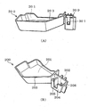
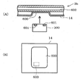
도 13(A) 및 (B)와 같이 본 실시형태에 의한 도어 포켓(200)(냉장고용 도어 포켓에 상당함)은 물품을 수납하는 수납부(201)와, 카메라 장치(300)를 유지하기 위한 유지부(202)를 구비하고 있다. 즉, 이 도어 포켓(200)은 특허청구의 범위에 기재한 냉장고용 도어 포켓과 냉장고용 홀더의 기능을 구비하고 있다. 또한, 유지부(202)는 촬상 수단을 부착하기 위한 피부착부에 상당한다고도 할 수 있다. 또한, 수납부(201)에 주목한 경우, 도어 포켓(200)은 유지부(202)에 유지된 카메라 장치(300)(즉, 촬상 수단)에 인접하여 설치되어 있다고도 할 수 있다.As shown in Figs. 13A and 13B, the door pocket 200 (corresponding to a door pocket for a refrigerator) according to the present embodiment includes a
수납부(201)는 유지부(202)측의 벽부(203)가 유지부(202)로부터 이격하는 방향으로 비스듬히 형성되어 있다. 즉, 도어 포켓(200)은 유지부(202)에서 카메라 장치(300)를 유지한(부착한) 경우, 그 카메라 장치(300)의 시야를 방해하지 않도록 시야의 외연(外緣)을 따른 형상으로 형성되어 있다.The
유지부(202)는 본 실시형태에서는 상부측(도 3(A)의 도시 상방측)이 개구한 대체로 상자 형상으로 형성되어 있고, 상부측의 개구로부터 카메라 장치(300)가 출입(착탈)된다. 또한, 유지부(202)의 전방면측(즉, 고내를 향하는 측)의 벽부(204)는 카메라 장치(300)를 유지한 상태에서 렌즈(301)및 촬상 램프(302)(도 15 등 참조. 카메라측 조명 수단, 조명 수단에 상당함)에 대응하는 위치에 절개부(205)가 형성되어 있고, 카메라 장치(300)의 시야를 방해하거나 조명이 반사되는 것이 방지되어 있다.In the present embodiment, the holding
또한, 유지부(202)에는 자석(206)이 설치되어 있다. 이 자석(206)은 카메라 장치(300)의 배면측에 대향하는 측이 N극 또는 S극 중 어느 것이 되도록 배치되어 있다. 또한, 자석(206)의 극성에 대해서는 후술하는 카메라 장치(300)의 구성에서 상세하게 설명한다.In addition, a
이 도어 포켓(200)은 도 14에 도시한 바와 같이 우측 문(3b)의 내판(14)에 부착된다. 이 때문에, 우측 문(3b)이 폐쇄된 상태에서는 카메라 장치(300)는 그 시야가 고내(냉장실(3))에 대향하는 배치가 된다. 이 때, 유지부(202)에 유지되는 카메라 장치(300)는 그 렌즈(301)의 중심이 냉장실(3)의 좌우 방향의 중심선(CL1)과, 냉장실(3)의 상하 방향의 중심선(CL2)이 교차하는 위치에 대응하여 유지된다. 즉, 이 상태에서의 카메라 장치(300)는 냉장실(3)의 중앙부를 중심으로 한 시야가 되도록 배치되어 있다. 구체적으로는 도어 포켓(200)의 경우, 도어 포켓(200)의 부착 위치와 카메라 장치(300)의 형상에 기초하여 수납부(201)의 저부(低部)보다 유지부(202)의 저부쪽이 약간 하방에 위치하는 형상으로 함으로써, 중심 위치가 최적이 되는 형상으로 되어 있다.This
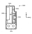
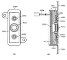
카메라 장치(300)는 도 15 및 도 16에 도시한 바와 같이 대체로 직방체의 형상으로 형성된 케이스(303)의 표면에 렌즈(301) 및 촬상램프(302)가 노출되도록 설치되어 있다. 또한, 렌즈(301) 및 촬상램프(302)가 직접 노출되어 있는 것이 아니라, 그 표면을 커버 등으로 덮고 있어도 좋다. 또한, 본 실시형태에서도 렌즈(301)는 광각 렌즈를 채택하고 있다.As shown in FIGS. 15 and 16, the
이하, 렌즈(301) 및 촬상램프(302)가 설치되어 있는 측(도 16의 경우, 도시 우측)을 카메라 장치(300)의 정면으로 하고, 반대측을 배면으로 하여 설명한다. 또한, 도 13에 도시한 바와 같이, 렌즈(301)와 촬상램프(302)가 냉장고(1)의 상하 방향으로 배치되는 방향을 세로방향이라고 하고, 후술하는 도 20과 같이 렌즈(301)와 촬상램프(302)가 냉장고(1)의 좌우 방향으로 배치되는 방향을 가로방향이라고 부른다.Hereinafter, the side on which the
이 카메라 장치(300)는 도 16에 도시한 바와 같이, 케이스(303)내에 제어 기판(304), 전지(305), 통신 모듈(306), 검지부(307)가 수용되어 있다. 제어 기판(304)에는 렌즈(301)나 도시하지 않은 촬상 소자를 갖는 촬상부(308)(도 21 참조), 본 실시형태에서는 2개의 촬상램프(302) 및 이들을 제어하기 위한 제어부(309)(도 21 참조) 등이 설치되어 있다. 촬상 소자는 CCD나 CMOS등의 주지의 촬상 소자이며, 그 형상이 장방형으로 되어 있다. 본 실시형태의 경우, 촬상 소자의 길이 방향이 상하 방향(즉, 케이스의 세로 방향)이 되도록 배치되어 있다. 이 때문에 일반적으로는 세로로 길게 형성되어 있는 냉장실(3)을 촬상할 때는 카메라 장치(300)를 세로로 놓음으로써, 촬상 소자를 세로로 긴 방향으로 배치할 수 있다. 한편, 후술하는 바와 같이 가로로 길게 형성되어 있는 야채실(4)을 촬상할 때는 카메라 장치(300)를 가로로 놓음으로써, 촬상 소자를 가로로 긴 방향으로 배치할 수 있다. 또한, 촬상램프(302)로서 본 실시형태에서는 LED를 채용하고 있다. 또한, 도시는 생략하지만 카메라 장치(300)에는 전원 스위치도 설치되어 있다.16, the
전지(305)는 리튬 전지로 구성되어 있고, 제어부(309)나 통신 모듈(306) 또는 검지부(307) 등에 전력을 공급한다. 이 전지(305)는 케이스(303)의 최하부측이고, 케이스의 전후 방향(도시 좌우 방향)의 대체로 전역을 점유하는 배치로 되어 있다. 케이스(303)에 수납되어 있는 각 부재 중 비교적 중량이 큰 전지(305)를 그러한 배치로 함으로써, 카메라 장치(300)를 설치했을 때의 밸런스가 어느 정도 확보되어 있다. 또한, 중심을 카메라 장치(300)의 하부(세로 배치의 경우)로 함으로써, 카메라 장치(300)를 우측 문(3b)의 도어 포켓(200)에 배치한 경우에서, 문 개폐시의 원심력이나 진동 등에 의해 카메라 장치(300)가 도어 포켓(200)으로부터 떨어져 나오는 것 등이 방지된다. 또한, 리튬 전지를 사용함으로써 냉장고(1)내와 같이 비교적 저온의 장소이어도 뛰어난 방전 특성을 나타내게 된다.The
또한, 도 25에 도시한 바와 같이, 본 실시형태의 가전 네트워크 시스템(500)에서는 냉장고(1)측에 카메라 장치(300)의 통신 모듈(306)과는 다른 별도의 통신 장치(501)가 설치되어 있고, 이 통신 장치(501)에 의해, 냉장고(1)는 외부 장치로부터의 촬상 지령을 수신한다. 또한, 이 통신 장치(501)는 냉장고(1)에 부착되어 있고, 카메라 장치(300)는 냉장실(3) 내에 배치되어 있다. 이 통신 장치(501)는 고내를 촬상하기 위한 지령(이하, 촬상 지령이라고도 함)을 외부의 장치로부터 수신하기 위한 고(庫)측 통신수단을 구성하고 있다. 본 실시형태에서는 통신 장치(501)는 무선 통신용의 어댑터로서 형성되어 있고, 냉장고(1)에 대해서 착탈 가능하게 되어 있다. 이 때문에 냉장고(1)를 구입한 사용자가 구입 후에 옵션으로서 설치하는 것도 가능해져 있다. 이 통신 장치(501)는 도 21에 도시한 바와 같이, 냉장고(1)의 주제어부(30)와의 사이에서 무선 통신 방식이나 유선 통신 방식에 의해 통신 가능하게 되어 있다. 그리고, 냉장고(1)는 상세한 내용은 후술하지만, 촬상 지령을 수신하면, 카메라 장치(300)에 대해서 촬상 지시(도 23참조. 본 실시형태에서는 광의 점멸신호)를 알린다.25, a
카메라 장치(300)의 통신 모듈(306)은 라우터(101)와의 사이에서 통신 가능하게 구성되어 있고, 통신 단말(103)이나 서버(104)에 화상 정보를 송신한다. 이 통신 모듈(306)은 카메라 장치(300)에서 촬상한 고내의 화상 정보를 통신 단말(103)이나 서버(104)(도 1 참조)등의 외부 장치에 송신하기 위한 카메라측 통신수단으로서 기능한다. 또한, 이 통신 모듈(306)은 카메라 장치(300)의 케이스(303)의 배면측(최외연측)의 벽부를 따라서 설치되어 있다. 즉, 통신 모듈(306)은 내장하는 도시하지 않은 안테나와 케이스(303)와의 사이에 다른 부품 등이 존재하지 않는 내부 배치로 함으로써 안테나에 의한 전파의 송수신이 저해되는 것(통신 장애가 발생하는 것)이 억제되어 있다. 또한, 통신 모듈(306)은 전지(305)에 대해서 수직 방향으로 배치되어 있고, 안테나와 전지(305)가 대향하지 않는 배치로 되어 있다.The
그리고, 냉장고(1)의 우측 문(3b)의 전방면은 상기한 바와 같이 유리 재료로 형성되어 있는 점에서, 고내에 배치된 카메라 장치(300)로부터 발해지는 무선 통신용 전파는 금속판 등을 사용하는 경우에 비하여, 문을 투과하기 쉬워지고 있다. 또한, 카메라 장치(300)는 도어 포켓(200)의 유지부(202)(즉, 우측 문(3b)의 개방단부측)에 배치되어 있으므로, 특히 본 실시형태와 같이 좌우 여닫이형인 경우에는 각 문 틈으로부터 전파를 고외로 내보낼 수 있다. 또한, 유지부(202)에 배치함으로써, 예를 들어 문의 전방면이 금속재료로 형성되어 있는 경우 등이어도, 카메라 장치(300)로부터의 전파가 고외로 나오기 쉬워진다. 또한, 문의 내부는 우레탄으로 충전되어 있으므로, 전파를 차단할 가능성이 적다.Since the front surface of the
그런데, 냉장고(1)에는 단열재로서 우레탄 대신, 또는 우레탄과 함께 진공 단열재가 사용되는 경우가 있다. 이 진공 단열재는 금속제의 박(箔) 부재(예를 들어, 알루미늄박)와 예를 들면 합성 수지제의 필름 부재를 접합시킨(라미네이트 가공한)필름으로 유리 섬유 등의 심재를 감쌈으로써, 예를 들면 장방형의 박판 형상으로 형성되어 단열재가 된다. 이 진공 단열재는 냉장고(1)의 케이스나 문의 내부 부재로서 사용되지만, 예를 들면 카메라 장치(300)를 도어 포켓(200)에 배치하는 경우에는 유지부(202)에 대응하는 위치를 피하여 진공 단열재를 설치하는 등에 의해, 전파를 내보내기 쉽게 할 수 있다.However, in the
이 경우 우측 문(3b)에 대해서는 카메라 장치(300)의 투영면(특히 통신 모듈(306)의 부위)을 피하도록 진공 단열재를 배치하거나, 좌측 문(3a)이나 하부 냉동실(7)의 문(7a) 등, 카메라 장치(300)가 배치되지 않은 문에 대해서는 그 전면(全面)에 진공 단열재를 배치하기 등에 의해, 냉장고(1)의 단열성을 저하시키지 않고 전파를 밖으로 나오기 쉽게 할 수 있다. 또한, 상술한 유리판(3b1)을 보강하는 것이나 후술하는 도 29와 같이 자석으로 카메라 장치(300)를 부착하기 위한 금속 부재를 문에 설치하는 것도 생각되는데, 그 경우도 진공 단열재의 경우와 동일하게 배치를 연구함으로써 전파를 나오기 쉽게 할 수 있다.In this case, for the
이와 같이, 고내로부터 전파를 나오기 쉽게 하는 구조는 본 실시형태와 같이 카메라 장치(300)에 통신 모듈(306)을 설치하고, 그 카메라 장치(300)를 냉장고(1)의 고내에 배치하며, 촬상한 화상 정보를 카메라 장치(300)로부터 직접적으로 외부 장치에 전달하는 구성(즉, 냉장고(1)의 통신 장치(501)를 통하지 않고 카메라 장치(300)가 화상 정보를 송신하는 구성)에서 특히 유의해진다.As described above, in the structure for facilitating the radiating of radio waves from the inside of the room, the
여기에서 상술한 자석(206)의 극성에 대해서 설명한다.Here, the polarity of the above-described
자석(206)은 도 17에 도시한 바와 같이, 유지부(202)에서 카메라 장치(300)의 배면 즉 검지부(307)에 대응하는 위치에 설치되어 있다. 이 때문에, 카메라 장치(300)가 유지되어 있는 상태에서는 검지부(307)가 자석(206)과 대향한 상태, 또한 자석(206)과 접근한 상태가 된다. 이 경우, 자석(206)은 카메라 장치(300)와 대향하는 측이 N극이 되도록 배치되어 있다. 이 때문에, 검지부(307)는 N극으로부터의 자계의 강도를 검지하는 것이 된다.17, the
그런데, 자석(206)의 극성을 이와 같은 배치로 하는 이유는, 카메라 장치(300)를 냉장실(3) 이외의 예를 들면 야채실(4) 등에 설치하는 것을 고려하고 있기 때문이다. 야채실(4)은 도 18에 도시한 바와 같이, 문(4a)에 레일 부재(4b)가 부착되어 있고, 그 레일 부재(4b)에 야채실 박스(4c)가 부착된 구조로 되어 있다. 이와 같은 야채실(4)을 카메라 장치(300)로 촬상하기 위해서, 본 실시형태에서는 도 19에 도시한 냉장고용 홀더(400)를 채용하고 있다. 이 냉장고용 홀더(400)는 카메라 장치(300)를 유지하는 유지부(401)와, 유지부(401)를 야채실 박스(4c)에 부착하기 위한 걸림고정부(402)를 구비하고 있다. 이 유지부(401)는 카메라 장치(300)를 가로배치로 유지 가능한 형상으로 형성되어 있고, 또한 전면측의 전방벽(403)은 렌즈(301)의 시야를 가리지 않는 높이로 형성되어 있다.The reason why the polarity of the
그리고, 유지부(401)의 후방벽(404)에는 카메라 장치(300)의 배면측의 위치에 자석(405)이 설치되어 있다. 이 자석(405)은 카메라 장치(300)측이 S극이 되도록 배치되어 있다. 이 때문에, 도 20에 도시한 바와 같이 냉장고용 홀더(400)를 야채실(4)에 부착하고, 카메라 장치(300)를 유지부(401)에 유지한 상태에서는, 카메라 장치(300)는 가로 배치의 상태로 유지되고, 또한 검지부(307)가 도 17과 동일하게 자석(405)에 대향한다. 그리고, 검지부(307)는 S극으로부터의 자계의 강도를 검지한다.A
이와 같이, 자석(206) 및 자석(405)은 카메라 장치(300)에 대향하는 측의 극성이 서로 반대가 되도록 배치되어 있다. 이 때문에, 카메라 장치(300)는 냉장실(3)에 설치된 경우와 야채실(4)에 설치된 경우에서, 다른 자계의 강도를 검지부(307)에서 검지한다. 다시 말하면, 카메라 장치(300)는 자신이 어느 저장실에 설치되었는지를 검지하는 것이 가능해진다. 또한, 카메라 장치(300)는 자기(磁氣)를 검지함으로써, 설치된 냉장고(1)가 자신의 동작 대상인지를 식별할 수 있다. 즉, 자석(206) 및 자석(405)은 특허청구의 범위에 기재한 피검지수단으로서도 기능한다.As described above, the
다음에, 이 카메라 장치(300)의 전기적 구성 등에 대해서 설명한다.Next, the electrical configuration and the like of this
도 21에 도시한 바와 같이, 카메라 장치(300)는 제어부(309)를 구비하고 있다. 이 제어부(309)는 CPU(309a), ROM(309b), RAM(309c) 및 RTC(309d) 등을 갖는 마이크로 컴퓨터로 구성되어 있고, 카메라 장치(300) 전체를 제어하는 카메라측 제어 수단으로서 기능한다. 구체적으로는 제어부(309)는 렌즈(301)나 촬상 소자를 갖는 촬상부(308)에 의한 촬상 타이밍을 제어, 촬상램프(302)에 의한 촬상할 때의 촬상 환경을 정리하는 제어(점등 제어), 통신 모듈(306)에 의한 화상 정보의 송신 및 후술하는 지령의 수신 등을 위한 제어, 검지부(307)에 의한 설치 상태를 판단·식별하기 위한 제어를 실시한다. 또한, 제어부(309)는 본 실시형태에서는 촬상한 화상의 보정 등을 실시하는 화상 처리도 실시하고 있다.As shown in Fig. 21, the
우선, 검지부(307)에 의한 설치 상태의 판단·식별의 제어에 대해서 설명한다. 검지부(307)는 온도 센서(310), 자기 센서(311), 가속도 센서(312) 및 조도 센서(313)를 갖고 있다. 제어부(309)는 온도 센서(310)에 의해 외부의 온도를 검지함으로써, 카메라 장치(300)가 모두 저장고에 설치되어 있는지의 설치 장소를 판단한다. 이하, 구체적인 판단에 대해서 설명한다.First, control of determination and identification of the installation state by the
온도 센서(310)는 카메라 장치(300)가 설치된 장소의 온도를 검지한다. 이 온도 센서(310)는 도 22(A)에 도시한 바와 같이, 온도에 비례하여 출력이 커진다. 그리고, 일반적으로는 냉장실(3)의 온도와 하부 냉동실(7)의 온도는 십여 ℃ 정도의 차이가 있는 점에서, 기준이 되는 기준 온도를 설정해 두고, 그 기준 온도보다 높으면 냉장실(3)에 설치되어 있다고 판단하는 한편, 기준 온도보다 낮으면 하부 냉동실(7)에 설치되어 있다고 판단한다. 이 경우, 하부 냉동실(7)에 설치되어 있다고 판단한 경우, 고장 등의 우려가 염려되므로, 촬상 램프(302)를 점등시키거나 부저 등의 음성 출력 수단을 설치해 두고 음성으로 설치 장소가 상정(想定) 밖인 것을 알리거나 통신 모듈(306)을 통하여 냉장고(1)측에 그 취지를 송신하여 냉장고(1)의 조작 패널(33) 등에서 사용자에게 알린다. 이와 같이, 카메라 장치(300)는 온도 센서(310)에서 검지한 온도에 기초하여 설치 장소를 판단한다.The
자기 센서(311)는 상기한 바와 같이 자석(206)이나 자석(405)으로부터의 자계를 검지 한다. 이 자기 센서(311)는 도 22(B)에 도시한 바와 같이, N극 또는 S극 중 어느 것으로부터의 자계인지에 따라 출력이 정측(N극인 경우)과 부측(S극인 경우)으로 변화하므로, 그 정부(正負)에 의해서 설치 장소를 판단할 수 있다. 즉, 자기 센서(311)의 출력이 정측(0이 아님)인 경우에는 본 실시형태에 대해서는 상술한 바와 같이 냉장실(3)의 도어 포켓(200)에 설치되어 있는 자석(206)에 대향하는 위치에 설치된 것, 즉 카메라 장치(300)가 냉장실(3)에 설치된 것을 검지할 수 있다.The magnetic sensor 311 detects a magnetic field from the
또한, 냉장실(3)과 야채실(4)에 온도차가 있는 경우에는, 이 온도 센서(310)의 출력에 기초하여 냉장실(3)에 설치되었는지 야채실(4)에 설치되었는지를 판단하도록 해도 좋다. 어쨌든, 온도 센서(310)의 출력에 기초하여 카메라 장치(300)가 저장실 내에 설치된 것을 검지할 수 있다.When there is a temperature difference between the refrigerating
한편, 자기 센서(311)의 출력이 부측(0이 아니라)인 경우에는, 상기한 자석(405)에 대향하는 위치에 설치된 것, 즉 카메라 장치(300)가 야채실(4)에 설치된 것을 검지할 수 있다. 또한, 카메라 장치(300)를 예를 들면 선반판(11) 등에 설치하는 경우(도 24(B)참조)를 고려하여, 본 실시형태에서는 정측 기준치를 넘은 경우에는 냉장실(3)이라고 판정하고, 부측 기준치를 하회한 경우에 야채실(4)이라고 판단하는 구성으로 하고 있다. 그리고, 0부근의 출력의 경우에는 자석이 설치되어 있지 않은 선반판(11) 등이라고 판단한다. 또한, 상술한 온도 센서(310)와 조합하여, 저장실 내임을 판단 조건에 추가해도 좋다.On the other hand, when the output of the magnetic sensor 311 is on the negative side (not zero), it is detected that it is installed at the position facing the
가속도 센서(312)는 카메라 장치(300)에 가해지는 가속도(중력 가속도)를 검지한다. 이 가속도 센서(312)는 이른바 3축 센서로서 X방향, Y방향 및 Z방향(도 15, 도 16 참조)의 3축 방향의 가속도를 검지한다. 이 때문에, 도 22(C)에 도시한 바와 같이 세로 배치한 경우와, 세로 배치(상하 역방향)한 경우와, 가로 배치한 경우와, 가로 배치(좌우 역방향)한 경우에서, 그 출력이 변화된다. 이에 의해, 카메라 장치(300)가 설치된 방향을 검지할 수 있다. 검지한 카메라 장치(300)의 방향은 후술하는 화상 처리에 이용된다. 또한, 설치 장소의 판단에 사용해도 좋다.The
다음에, 촬상 타이밍에 대해서 설명한다. 또한, 촬상의 흐름은 제1 실시형태의 도 6과 거의 공통이므로, 도 6도 참조하면서 설명한다.Next, the imaging timing will be described. Since the flow of imaging is almost the same as that in Fig. 6 of the first embodiment, it will be described with reference to Fig.
카메라 장치(300)는 미리 정해져 있는 소정 시간이 경과한 경우, 및 외부 장치로부터의 지령을 수신한 경우 중 어느 것을 판정하고 있다. 즉, 촬상 조건이 충족되었는지의 여부를 판정하고 있다(A1). 이 경우 카메라 장치(300)는 RTC(309d)에 의해 계시(計時)를 실시함으로써, 소정 기간이 경과했는지를 판정하고 또한 지령을 수신했는지 여부를 조도 센서(313)에서 검지한 조도에 기초하여 판정한다.The
검지부(307)를 구성하는 조도 센서(313)는 카메라 장치(300)가 설치된 장소의 조도를 검지한다. 본 실시형태의 경우, 조도 센서(313)는 고내 조명이 점등된 정도의 조도가 되면, 그 취지를 제어부(309)에 통지한다. 또한, 카메라 장치(300)가 설치된 본 실시형태의 냉장고(1)는 외부의 장치로부터 촬상하기 위한 지령을 수신하면, 예를 들면 천정 조명(13)과 같은 고내 조명을 소정의 점멸 패턴으로 점멸시킨다. 또한, 촬상 지령은, 예를 들면 통신 단말(103)의 경우에는 제1 실시형태의 도 10의 단말측 처리의 단계(B2~B4)와 동일하게 실시된다.The
이 점멸 패턴은 냉장고(1)로부터 착탈 가능한 카메라 장치(300)에 대해서 촬상 타이밍을 알리기 위해 미리 설정되어 있다. 즉, 냉장고(1)는 고내 조명을 점멸시킴으로써 카메라 장치(300)에 대해서 촬상 지시를 알린다. 이는 상술한 바와 같이, 냉장고(1)가 동작 대상인지(즉, 고내 조명의 점멸이 가능한 냉장고인지)를 판단 가능하게 하는 구성이나, 카메라 장치(300)에 동작 대상임을 식별시키기 위한 구성을 설치함으로써 실현되어 있다. 즉, 고내 조명을 점멸 가능한 것이, 카메라 장치(300)의 동작 대상인 냉장고(1)임을 나타내고 있다.This flashing pattern is set in advance to inform the
카메라 장치(300)는 도 23의 기간 T1에 도시한 바와 같이, 통상은 소위 슬립 모드 등의 전력 절감 상태가 되어 있는 한편, 조도 센서는 작동하고 있다. 냉장고(1)는 외부의 장치로부터 지령을 수신하면, 상기한 것처럼 소정의 점멸 패턴으로 고내 조명을 점멸시킨다. 이때, 고내 조명이 점등된 점에서 조도 센서(313)로부터 제어부(309)에 대해서 통지(예를 들면, 인터럽트 신호의 입력 등)이 실시되고, 제어부(309)가 동작 상태가 된다. 즉, 고내 조명이 소정의 점멸 패턴으로 점멸한 경우, 촬상 조건이 충족되었다고 판단한다. 점멸 패턴은 예를 들면 점등과 소등의 주기, 그 반복 횟수 등, 임의로 설정할 수 있다.As shown in the period T1 of FIG. 23, the
촬상 조건이 충족됐다고 판단하면(A1:예), 카메라 장치(300)는 촬상램프(302)를 점등시키고(A2), 고내를 촬상하고(A3), 그 화상 정보를 서버(104) 등으로 송신한다(A4).If the image pickup condition is satisfied (A1: YES), the
그런데, 냉장고(1)는 지령을 받은 경우 이외에도 고내 조명이 점등하는 경우가 있다. 예를 들어, 도 23의 기간 T2와 같이, 사용자에 의해 문이 개방된 경우에는, 점멸 패턴이 아닌 형태(이 경우 연속 점등)으로 고내 조명이 점등된다. 이 경우 카메라 장치(300)는 고내 조명이 점등한 점에서 일단은 동작 상태가 되지만, 소정의 점멸 패턴은 아니므로, 즉 촬상 조건이 충족되어 있지 않으므로 다시 대기 상태가 된다.Incidentally, the refrigerator (1) may be turned on when not instructed. For example, when the door is opened by the user as in the period T2 of FIG. 23, the internal illumination is turned on in a mode other than the flashing pattern (continuous lighting in this case). In this case, the
또한, 카메라 장치(300)는 도 23의 기간 T3처럼, 전회(기간 T1)의 촬상으로부터 미리 설정되어 있는 촬상 간격 설정 기간이 경과하는 등, 소정 기간이 경과하면, 촬상 조건이 충족됐다고 판정하고(A1: YES), 동작 상태가 되어, 촬상램프(302)를 점등시키고(A2), 그 시점에서의 고내의 화상을 촬상하고(A3), 화상 정보를 송신한다(A4).Further, the
이와 같이, 카메라 장치(300)는 소정 기간이 경과했는지 및 외부 장치로부터의 지령(사용자의 의사)이 있었는지에 기초하여 고내를 촬상한다. 그리고, 사용자는 도 24(A)~(C)에 나타낸 바와 같이, 카메라 장치(300)를 설치한 장소에 따라, 고내의 모습을 확인할 수 있다. 또한, 카메라 장치(300)를 냉장실(3)과 야채실(4)의 쌍방에 설치하는 등, 복수의 카메라 장치(300)를 설치해도 좋다.As described above, the
그런데, 본 실시형태의 경우 카메라 장치(300)는 단순히 고내를 촬상할 뿐만 아니라, 화상의 변환 등의 화상 처리도 실시하고 있다. Incidentally, in the case of the present embodiment, the
카메라 장치(300)는 상기한 바와 같이 세로배치 또는 가로배치할 수 있지만, 이 경우, 화상은 90도(또는 270도) 회전한 상태로 되어 있다. 그 때문에, 카메라 장치(300)는 서버(104)에 송신하기 전에 화상의 변환을 실시하고 있다. 이에 의해, 도 24(A)와 (B) 또는 (C)에 도시한 바와 같이, 카메라 장치(300)의 방향이 다른 경우에도, 상하 방향이 통일된 화상, 즉 사용자가 냉장고(1)를 직접 확인할 때 와 동일한 상태의 화상을 통신단말(103)에서 표시시킬 수 있다.The
또한, 렌즈(301)가 광각 렌즈이므로, 촬상한 화상은 제1 실시형태의 도 7에 도시한 바와 같이 중앙 부근이 변형된 화상이 된다. 그 때문에 카메라 장치(300)는 그 변형을 보정하는 화상 처리를 함으로써, 구체적으로는 중앙 부근과 상하의 단부와의 비율을 일치시키는 화상 처리를 실시함으로써, 도 24(A)에 도시한 바와 같이, 변형이 적은 화상을 표시 가능하게 하고 있다. 또한, 화상과 카메라 장치(300)의 방향을 맞추어 화상 정보로서 송신하고, 서버(104) 또는 통신 단말(103)에서 화상 처리를 실시하는 구성으로 해도 좋다. 화상 처리를 외부의 장치측에서 실시함으로써 카메라 장치(300)의 소비 전력을 삭감할 수 있다. 이는 본 실시형태와 같이 외부로부터의 급전수단을 갖지 않는 카메라 장치(300)에 있어 유의하다.Further, since the
이상 설명한 본 실시형태에 따르면, 제1 실시형태에서 얻어지는 효과에 추가하여(또는 대신), 다음과 같은 효과를 갖는다.According to the present embodiment described above, in addition to (or instead of) the effect obtained in the first embodiment, the following effects are obtained.
외출지 등의 원격지에서 냉장고(1)의 고내를 확인하고 싶다고 생각하는 사용자가 존재하지만, 고내를 촬상하기 위한 촬상부(308)(촬상 수단)와, 촬상부(308)에서 촬상한 고내의 화상 정보를 서버(104) 등의 외부 장치에 송신하기 위한 통신 모듈(306)(통신수단)과 냉장고(1)에 설치되어 있으므로, 외출지 등에서, 통신 단말(103)에 의해 고내의 화상을 취득할 수 있고 고내를 확인할 수 있다.There is a user who wants to check the interior of the
고내의 화상을 촬상할 때 함부로 촬상을 반복하면 전력 소비가 증가하여 전지 방전을 일으키거나 서버(104)에 불필요한 (동일한) 화상이 몇 장이나 축적될 우려가 있지만, 카메라 장치(300)의 제어부(309)에 의해 고내를 촬상하는 타이밍을 제어함으로써 그러한 우려를 감소시킬 수 있다.If the image pickup is repeatedly performed at the time of capturing an image in the solid image, there is a possibility that electric power consumption increases and battery discharge is caused or a few unnecessary (identical) images are accumulated in the
구체적으로는 실시형태와 같이, 소정 기간이 경과한 경우에는 예를 들면 가족 등이 냉장고(1)로부터 식재료를 꺼내는 등의 행위를 실시할 가능성이 있으므로, 소정 기간을 경과한 타이밍, 즉 저장상황이 변화되었을 가능성이 있는 타이밍에서 고내를 촬상함으로써, 불필요하게 촬상이 반복되는 것을 방지할 수 있다.Specifically, as in the embodiment, when a predetermined period of time has elapsed, for example, there is a possibility that a family member or the like may perform an action such as taking out a food material from the
또한, 사용자로부터의 지령을 수신한 타이밍에서 고내를 촬상함으로써 최신의 저장 상황을 파악할 수 있다. 이 경우, 상기한 소정 기간이 경과한 타이밍에서 촬상하지 않으면, 다시 말하면, 사용자의 의사 표시가 되었을 때에만 촬상하도록 하면, 불필요한 촬상이 실시되지 않게 되므로, 더욱 소비 전력을 삭감할 수 있다. 또한, 실시형태에서도 설명했지만, 제1 실시형태의 각 촬상 조건과 조합함으로써 저장 상황이 변화했을 때의 화상을 취득하도록 해도 좋다.Further, the latest storage state can be grasped by capturing the inside of the room at the timing of receiving the command from the user. In this case, if imaging is not performed at the timing when the predetermined period elapses, that is, if imaging is performed only when the user's intention is displayed, unnecessary imaging is not performed, and further power consumption can be reduced. Also, as described in the embodiment, an image obtained when the storage condition is changed may be acquired by combining with the imaging conditions in the first embodiment.
냉장고(1)의 고내를 확인할 필요가 없다고 생각하는 사용자도 존재하는 것이 예상되지만, 카메라 장치(300)는 고내를 촬상하기 위한 촬상부(308)와, 촬상부(308)에서 촬상한 고내의 화상 정보를 서버(104) 등의 외부 장치에 송신하기 위한 통신 모듈(306)을 구비하고, 냉장고(1)에 착탈 가능한 구성으로 되어 있으므로, 확인이 불필요한 사용자는 카메라 장치(300)를 떼어낼 수 있다. 또한, 구입시에는 불필요하다고 생각했지만 구입후에 확인하고 싶다고 생각하는 사용자도 카메라 장치(300)를 추가함으로써 고내를 확인할 수 있게 된다.It is expected that there is a user who thinks that it is not necessary to check the inside of the
이 경우, 통신 장치(501)도 착탈 가능한 구성으로 하고 있으므로, 카메라 장치(300)의 경우와 동일하게, 고내의 확인이 필요 없는 사용자는 분리함으로써 소비 전력을 감소시킬 수 있고, 또한 나중에 추가로 달고자 하는 사용자에 대해서도 대응할 수 있다.In this case, since the
촬상하기 위해서는 광원이 필요하지만, 고내를 비추기 위한 촬상램프(302)(카메라측 조명 수단)를 카메라 장치(300)에 설치하고 있으므로, 카메라 장치(300) 단체(單體)로 고내를 촬상할 수 있다. 또한, 냉장고(1)와 연계하여 고내 조명을 점등하는 구성이어도 좋은 것은 물론이다.However, since the imaging lamp 302 (camera-side illumination means) for illuminating the inside of the living room is provided in the
카메라 장치(300)를 설치하는 경우, 설치 위치에 따라서는 시야가 가려지는 등에 의해 고내를 잘 촬상하지 못할 가능성도 있지만, 촬상하는 데 유리한 장소도 있다. 그래서, 냉장고(1)에 카메라 장치(300)를 부착하기 위한 피부착부(실시형태에서는 도어 포켓(200)의 유지부(202)나, 냉장고용 홀더(400)의 유지부(401)등)을 설치함으로써, 예를 들면 냉장실(3) 전역을 촬상 가능한 장소에 카메라 장치(300)를 설치할 수 있다.When the
카메라 장치(300)의, 상술한 바와 같은 고내 조명을 점멸시킬 수 없으면 외부의 장치로부터의 촬상지령을 실행할 수 없을 우려가 있지만, 자석(206)이나 자석(405)을 설치하여 그 자기를 검지부(307)에서 검지하는 구성으로 함으로써, 즉 그 냉장고(1)가 카메라 장치(300)에 의한 촬상이 가능한(촬상이 허용된) 동작 대상인 것을 검지시키기 위한 피검지 수단을 구비함으로써, 그와 같은 우려를 감소시킬 수 있다.There is a possibility that an image pickup command from an external device can not be executed unless the above-described internal illumination of the
이 경우, 통신 모듈(306)에서 냉장고(1)측과 통신함으로써, 즉 통신 모듈(306)을 검지수단(이 경우, 통신 장치(501)가 피검지 수단이 된다)으로서 사용해도 좋다. 또한, 통신 모듈(306)을 카메라 장치(300)가 상기 냉장고(1)용으로 설계된 것(예를 들면, 고내 조명을 점멸시킴으로써 촬상을 할 수 있는 것)인지를 식별하기 위한 식별 수단으로서 사용해도 좋다.In this case, the
카메라 장치(300)는 실시형태의 경우에는 전지(305)에 의해 구동되는(즉, 냉장고(1)에 설치되어 있을 때에는 외부로부터의 전원 공급이 없는 상태에서 구동되는)것으로부터, 가능한 한 전력 소비를 줄이는 것이 바람직하다. 그래서, 통신 모듈(306)은 통신 장치(501)와 통신하도록 함으로써, 통신 모듈(306)에서 외부의 장치와 무선 통신을 실시하는 경우에 비교하여 무선 통신에 의한 전력 소비를 감소시킬 수 있다.In the case of the embodiment, the
또한, 외부 장치로부터 지령을 받는 경우, 통신수단이 항상 동작하여 지령을 대기할 필요가 있지만, 실시형태처럼 통신 장치(501)에서 지령을 수신하는 구성으로 함으로써, 통신 모듈(306)을 상시 동작시켜 둘 필요가 없어지고, 전지가 방전될 때까지의 기간을 보다 길게 할 수 있다. 이 경우 통신 장치(501)에는 예를 들면 USB 등의 유선 방식에 의해 냉장고(1)측으로부터 급전 가능한 구성으로 해 두면, 통신 장치(501)가 없는 경우에는 불필요한 급전이 이루어지지 않게 되고, 통신 장치(501)가 있는 경우에는 예를 들면 상시 동작시킬 수 있게 된다.In the case of receiving a command from an external device, it is necessary for the communication means to always operate and wait for a command. However, by receiving a command from the
카메라 장치(300)를 착탈 가능하게 하는 경우, 무선 통신을 채용한 편이 편리성을 향상시킬 수 있지만, 상술한 바와 같은 통신 장치(501)에서 지령을 수신하는 경우, 그것을 어떤 방법으로 카메라 장치(300)에 전달할 필요가 있다. 그래서 카메라 장치(300)에 조도 센서(313)를 설치하고, 고내 조명을 점멸시킴으로써, 촬상 지령을 간접적으로 카메라 장치(300)에 전달하는 구성함으로써, 무선 통신을 채용한 카메라 장치(300)에, 촬상 타이밍을 통지할 수 있다. 이 경우, 카메라 장치(300)측은 조도 센서(313)를 동작 상태로 해 두면 좋으므로, 통신 모듈(306)을 동작시키는 경우에 비하여 전력 소비를 삭감할 수 있다.In the case where the
또한, 카메라 장치(300)가 설치되는 우측 문(3b)의 전방면은 비금속 재료로 형성되어 있으므로, 우측 문(3b)에 의해 밀폐된 냉장실(3)내에 카메라 장치(300)를 통신 모듈(306)마다 배치하는 경우이어도, 전파를 고외로 내보내기 쉽게 할 수 있다. 야채실(4)에 카메라 장치(300)를 배치하는 경우도 동일하다.Since the front surface of the
예를 들면 냉장실(3)은 일반적으로는 세로로 긴 형상이며 야채실(4)은 일반적으로는 가로로 긴 형상임을 고려하면 복수의 저장실이 존재하는 경우, 저장실에 따라서 카메라 장치(300)의 시야를 전환하는 것이 바람직하다. 또한, 화상이 가로방향이 되면 사용자가 위화감을 느낄 가능성이 있으므로, 사용자가 냉장고(1)를 본 경우의 상태, 즉 냉장고의 상하 방향이 통일된 화상으로 하는 것이 바람직하다. 그래서, 상술한 자석(206)이나 자석(405)을 설치함으로써, 또한 카메라 장치(300)에 대향하는 측의 극성이 다른 것과 같은 배치로 함으로써 어떤 위치(이 경우, 제조 업체 등이 미리 설정한 부착 위치. 유지부(202) 또는 유지부(401)에 대응함)에 설치되어 있는지를 파악함으로써, 그 위치에서의 카메라 장치(300)의 방향을 판단 가능하게 하고 있다. 또한, 냉장실(3)의 경우에는 본 실시형태에서 세로 배치, 야채실의 경우에는 가로배치가 되도록 유지부(202)나 유지부(401)가 미리 형성되어 있음으로써, 저장실에 대응한 방향으로 카메라 장치(300)가 설치되도록 하고 있다. 이에 의해, 저장실에 따라서 적절하게 시야를 확보할 수 있고, 또한 화상 처리를 실시할 때 어느 방향으로 회전시키면 좋을지 등을 판별할 수 있게 된다.For example, considering that the
이 경우, 가속도 센서(312)에서 검출한 가속도의 방향으로부터 카메라 장치(300)의 방향을 판단할 수도 있고, 온도 센서(310)에서 검출한 온도에 기초하여 설치 장소를 판단할 수도 있다.In this case, the direction of the
카메라 장치(300)가 예를 들면 냉동실에 잘못 설치되면, 동작 불량 등을 일으킬 가능성이 있지만, 온도 센서(310)에서 온도를 검지함으로써, 또한 실시형태와 같이 알림 가능하게 함으로써, 동작 불량 등을 일으킬 우려를 감소시킬 수 있다.If the
카메라 장치(300)에서 고내를 촬상하기 위해서는 고내에 대해서 정면으로부터, 또한 시야를 확보하기 위해 어느 정도의 거리를 확보하는 것이 바람직하지만, 냉장고(1)의 경우 그 정면측의 부착 위치는 문에 의해 제한된다. 그래서, 적어도 거리를 확보하기 위해 문의 내판(14)에 부착하는 것이 생각되지만, 그 경우 도어 포켓이 시야에 걸릴 가능성이 있다. 그래서, 실시형태의 도어 포켓(200)은 그 벽부(203)가 유지부(202)(피부착부)를 피하는 형상으로 형성되어 있으므로, 카메라 장치(300)의 시야를 가리는 일이 없다.In order to capture the interior of the room by the
또한, 상술한 바와 같이 고내를 촬상하는 데에 유리한 장소가 존재하므로, 그 장소를 사용자에게 알리는 것이 바람직하다. 그래서, 도어 포켓(200)과 같이, 카메라 장치(300)를 유지하는 유지부(202)(부착하기 위한 피부착부)를 설치함으로서, 설치 장소를 명시할 수 있다. 또한, 유지부(202)에 유지된 상태에서는, 카메라 장치(300)의 시야가 냉장실의 중심에 오도록 유지부(202)가 형성되어 있으므로, 고내의 거의 전역을 촬상할 수 있다. 또한, 유지부(202)에 설치함으로써 그 중심 위치가 규정되므로 화상의 변형을 보정하는 화상 처리에서, 보정할 때의 중심 위치와 화상의 중심 위치가 일치하고, 그 중심 위치를 중심으로 하여 균등하게 변형 보정을 실시하면 좋으므로, 화상 처리의 연산 부하의 감소를 도모할 수도 있다.In addition, as described above, since there is a place advantageous for imaging the inside of the room, it is preferable to inform the user of the place. Thus, by providing a holding portion 202 (an attachment portion for attaching) for holding the
또한, 이 도어 포켓(200)에는 자기 센서(311)의 검지 대상이 되는 자석(206)을 설치하고 있으므로, 상기한 바와 같이 설치장소를 카메라 장치(300)에 식별시킬 수 있다.Since the
냉장고(1)의 경우, 야채실(4) 등도 설치되어 있지만, 야채실(4)에는 소위 도어 포켓이 설치되어 있지 않고, 또한 상자형상으로 형성되어 있는 점에서, 단순히 카메라 장치(300)를 설치하면, 수납되는 야채 등으로 덮일 우려가 있다. 그래서, 냉장고용 홀더(400)와 같이, 카메라 장치(300)를 유지하고 유지부(401)를 갖는 냉장고용 홀더(400)를 사용하여 카메라 장치(300)를 야채실(4)에 설치할 수 있다. 이 경우, 유지부(401)를 야채실 박스(4c)의 가장자리 등에 걸어 고정하는 걸림 고정부(402)를 구비하고 있으므로, 야채실(4)의 상부측 또한 문(4a)측에 설치할 수 있어, 채소 등에 덮이지 않고 야채실을 촬상 가능하게 할 수 있다. 또한, 걸림 고정부(402)에서 걸려 고정되어 있으므로, 불필요한 경우에는 용이하게 분리할 수 있다.In the case of the
또한, 이 냉장고용 홀더(400)에도 자석(405)을 설치하고 있으므로, 카메라 장치(300)는 자신의 설치 장소를 상기한 바와 같이 판단할 수 있다.Further, since the
또한, 가전 네트워크 시스템(500), 고내 화상 표시 프로그램이 나타내는 효과는 제1 실시형태와 공통이다.The effects of the home
(제3 실시형태)(Third Embodiment)
다음에, 제3 실시형태에 대해서 설명한다. 본 실시형태는 고내에 오목부를 설치하고, 그 오목부에 촬상 수단의 일례로서 촬상 카메라를 설치하는 구성을 기초로 하는 실시형태이다. 즉, 본 실시형태는 상세하게는 후술하는 우묵한 부분(600)과 같은 오목부를 전개한 실시형태이다. 또한, 상술한 실시형태에서는 고내의 측면의 일례인 문의 내면에 촬상 수단을 설치하는 구성을 예시했지만, 본 실시형태는 고내의 측면의 일례인 저장고의 내측면에 촬상 수단을 설치하는 구성을 예시한다.Next, the third embodiment will be described. This embodiment is an embodiment based on a configuration in which a concave portion is provided in a pit and an imaging camera is provided as an example of the imaging means in the concave portion. That is, this embodiment is an embodiment in which a concave portion like the recessed
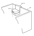
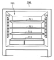
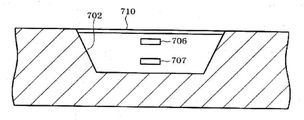
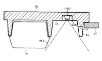
즉, 예를 들면 도 26 및 도 27에 도시한 바와 같이, 냉장고(700)의 저장고(701) 내에는 고외측으로 움푹 들어가고, 상하 방향으로 연장되는 세로로 긴 오목부(702)가 설치되어 있다. 이 경우, 오목부(702)는 저장고(701)내의 좌우의 양측면에 설치되어 있다. 또한, 예를 들어 도 28에 도시한 바와 같이, 오목부(702)는 저장고(701)내 중, 문(703)이 닫힌 상태에서 해당 문(703)과 간섭하지 않는 위치에 설치되어 있다. 따라서, 문(703)이 닫힌 상태에서 오목부(702)가 문(703)의 단열벽(704)이나 도어 포켓(705) 등에 의해 막히지 않게 되어 있다.26 and 27, a vertically elongated
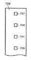
이 오목부(702)에는, 촬상 수단의 일례인 촬상 카메라(706) 및 조명 수단의 일례인 조명용 LED(707)가 수납되어 있다. 이 조명용 LED(707)는 촬상 카메라(706)에 의한 저장고(701)내의 촬상시에 저장고(701)내를 조명하기 위해서 설치된 것이다. 이 경우, 조명용 LED(707)는 저장고(701)내를 조명하기 위한 고내등(708)과는 별개의 요소로서 구비되어 있다.An
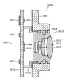
예를 들면 도 29에 도시한 바와 같이, 오목부(702)의 내부에는 기반(基盤)(709)이 설치되어 있다. 이 기반(709)은 기본적으로는 조명용 LED(707)가 실장되는 조명용 기반이다. 본 실시형태에서는 이 조명용 기반(709)에 촬상 카메라(706)가 부착되어 있다. 즉, 조명용 기반(709)은 촬상용 기반으로서의 기능도 겸비하고 있다. 따라서, 촬상 카메라(706) 및 조명용 LED(707)는 동일한 기반(709)상에 실장되어 있다. 또한, 예를 들면 도 30에 도시한 바와 같이, 촬상 카메라(706)는 오목부(702)내에서 조명용 LED(707)보다 고내측에 위치하도록 설치해도 좋다. 또한, 도시는 하지 않지만, 촬상 카메라(706)는 오목부(702)내에서 조명용 LED(707)보다 고외측에 위치하도록 설치해도 좋다.For example, as shown in FIG. 29, a
또한, 오목부(702)내에는 복수의 촬상 카메라(706) 및 복수의 조명용 LED(707)가 구비되어 있다. 그리고, 오목부(702)내에서 하나의 촬상 카메라(706)는 그 상하에 위치한 2개의 조명용 LED(707)에 끼인 상태로 되어 있다. 또한, 하나의 조명용 LED(707)는 그 상하에 위치하는 2개의 촬상 카메라(706)에 끼인 상태로 되어 있다.In the
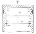
또한, 오목부(702)에는 상기 오목부(702)를 막는 「덮개」로서의 기능을 구비하는 예를 들어 수지제의 방호 커버(710)가 착탈 가능하게 부착되어 있다. 이 방호 커버(710) 중 조명용 LED(707)에 대향하는 부분에는 요철이 형성되어 있다. 이 요철에 의해, 조명용 LED(707)로부터 조사되는 광이 산란되고 고내에 공급되도록 이루어져 있다. 또한, 이 방호 커버(710) 중 촬상 카메라(706)에 대향하는 부분에는 요철이 형성되어 있지 않다. 따라서, 촬상 카메라(706)는 방호 커버(710)의 요철에 방해받지 않고 고내를 선명하게 촬상하는 것이 가능해져 있다.In addition, a resin
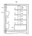
또한, 예를 들어 도 26에 도시한 바와 같이, 촬상 카메라(706)는 저장고(701)내에 설치된 선반(711)과는 다른 높이 위치에 설치하며 좋다. 또한, 조명용 LED(707)도 선반(711)과는 다른 높이 위치에 설치하면 좋다. 이 경우, 예를 들면 도 31에 도시한 바와 같이, 선반(711)의 전방부(전단부)에는 광택(T)이 처리되어 있다. 도 31에서는 이 광택(T)을 사선으로 나타내고 있다. 이 광택(T)은 예를 들면, 광택을 갖는 부재를 부착함으로써 또는 광택 도료를 도포함으로써 실현되어 있다. 이 경우, 조명용 LED(707)의 조사 방향 D1은 선반(711)의 전방부에는 지향하고 있지 않고, 따라서 조명용 LED(707)에서 조사되는 광이 광택(T)에 의해 반사되기 어려운 구성이 실현되어 있다.26, the
또한, 예를 들어 도 26에 도시한 바와 같이, 촬상 카메라(706)는 문에 설치되어 있는 도어 포켓(705)과 선반(711) 사이에 설치되어 있다. 또한, 촬상 카메라(706)는 고내에 설치된 선반(711)보다 전방측에 위치하고 있다. 이 경우, 예를 들면 도 32에 도시한 바와 같이, 촬상 카메라(706)를, 선반(711)을 향해서 지향시켜 배치해도 좋다.26, the
또한, 예를 들어 도 33에 도시한 바와 같이, 촬상 카메라(706)는 오목부(702)의 측벽, 이 경우 특히 전방측의 측벽 및 후방측의 측벽이 해당 촬상 카메라(706)의 시야 R내에 들어가지 않는 위치에 설치하면 좋다. 또한, 예를 들어 도 34와 같이, 촬상 카메라(706)는 오목부(702)의 측벽, 이 경우 특히 전방측의 측벽 및 후방측의 측벽을 지향하지 않는 범위에서, 그 설치 각도를 적절히 조정하여 설치하면 좋다. 또한, 오목부(702)는 그 저부가 되는 고외측이 좁고, 그 개구부가 되는 고내측이 넓은 형상이 되도록 설치하면 좋다. 이 경우, 오목부(702)는 고내측을 향할수록, 그 측벽이 서서히 넓어져 가는 형태가 된다. 이에 의해, 오목부(702)의 측벽이 촬상 카메라(706)의 시야 R내에 들어가기 어려운 구성을 실현할 수 있다.33, the
또한, 예를 들어 도 35에 도시한 바와 같이, 촬상 카메라(706)는 조명용 LED(707)의 조사 방향 D1과 동일한 방향으로 지향하도록 설치하면 좋다.35, the
또한, 예를 들어 도 36에 도시한 바와 같이 촬상 카메라(706)의 시야각 α와 조명용 LED(707)의 조사각 β가 다르도록 설치해도 좋다. 또한, 촬상 카메라(706)의 시야각 α는 조명용 LED(707)의 조사각 β보다 좁은 각도로 설정하면 좋다. 이에 의해 촬상 카메라(706)의 시야 R전체를 조명용 LED(707)에 의해서 조사 가능하게 할 수 있다.Further, for example, as shown in Fig. 36, the viewing angle? Of the
또한, 수납부인 오목부(702) 내부에 있는 조명용 LED(707)가 오목부(702)의 바닥면(고외측의 면)또는 저장실을 구성하는 내부상자의 측벽의 면에 대하여 비스듬히 지향하고 있는 경우에, 그 지향 방향을 전방측 또는 후방측의 측벽에 닿지 않도록 하면 좋다. 그렇게 함으로써, 측벽에 빛이 반사되어 그 반사광이 촬상 카메라(706)에 입사되는 것, 즉 역광이 되는 것을 억제할 수 있다.When the
또한, 촬상 카메라(706)와 조명용 LED(707)의 지향 각도를 다르게 하면 좋다. 이에 의해 설사 반사광이 발생한 경우에도 촬상 카메라(706)에 빛이 들어가기 어렵게 할 수 있다. 또한, 이 경우, 촬상 카메라(706)의 경사 각도는 조명용 LED(707)의 경사 각도보다 작은 각도로 하면 보다 효과적이다. 예를 들어, 조명용 LED(707)는 보다 고내 안쪽을 향하고, 촬상 카메라(706)는 조명용 LED(707)보다 고내 앞쪽(문쪽)을 지향하도록 배치하면 좋다.Further, the directivity angle of the
또한, 촬상 카메라(706)와 조명용 LED(707)의 지향 각도를 다르게 하는 경우에는 이들 촬상 카메라(706) 및 조명용 LED(707)를 동일한 기판에 배치하지 않아도 좋고, 이들 촬상 카메라(706) 및 조명용 LED(707)를, 각각 별도의 기판에 배치해도 좋다.When the directivity angle of the
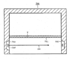
또한, 예를 들어 도 37에 도시한 바와 같이, 냉장고(700)는 저장고(701) 내 중, 한쪽의 측면(예를 들면 도 37에서는 좌측의 측면)에 설치된 촬상 카메라(706)에 의해서 저장고(701) 내를 촬상할 때는 그 촬상 카메라(706)에 대향하는 면(이 경우 도 37에서는 우측의 측면)에 설치되어 있는 조명용 LED(707)를 소등하도록 설정하면 좋다. 이 경우, 한쪽의 측면에 설치된 촬상 카메라(706)의 지향 방향 D2(촬상 중심이 되는 촬상축)와 다른쪽의 측면에 설치된 조명용 LED(707)의 조사 방향 D1(조사 중심이 되는 광축, 조사축)과는 서로 대향하지 않도록 구성하면 좋다. 이에 의해 한쪽의 측면에 설치된 촬상 카메라(706)의 렌즈에, 다른쪽의 측면에 설치된 조명용 LED(707)에서부터 빛이 들어가기 어려운 구성, 즉 역광이 되기 어려운 구성을 실현할 수 있다.37, the
또한, 냉장고(700)는 저장고(701)내 중, 한쪽 측면(예를 들면 도 37에서는 좌측의 측면)에 설치된 촬상 카메라(706)에 의해서 저장고(701) 내를 촬상할 때는 그 촬상 카메라(706)와 동일한 면에 설치되어 있는 조명용 LED(707)를 점등하도록 설정하면 좋다. 이에 의해 한쪽의 측면에 설치된 촬상 카메라(706)에 의해서 저장고(701) 내를 촬상하는 경우에는 그 촬상 카메라(706)와 동일한 면에 설치된 조명용 LED(707)에 의해서 역광이 되지 않고 고내를 조사할 수 있다.When the inside of the
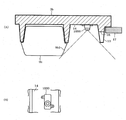
또한, 촬상 카메라(706)는 문(703)의 내면에 설치되어 있는 도어 포켓(705)을 촬상 가능한 위치에 설치하면 좋다. 즉, 예를 들면, 촬상 카메라(706)는 도어 포켓(705)보다 상방에 있어서, 해당 도어 포켓(705)과는 다른 높이 위치에 설치하고, 또한 도어 포켓(705)을 위에서 아래를 향하여 비스듬히 촬상 가능한 각도를 갖고 설치하면 좋다. 이에 의해, 촬상 카메라(706)는 도어 포켓(705)을 비스듬히 상방으로부터 촬상할 수 있다. 또한, 예를 들어 도 38에 도시한 바와 같이, 문(703)으로부터 고내에 연장하는 단열용 벽부(704)에 절개부(704a)를 설치하면 좋다. 이 구성에 따르면, 촬상 카메라(706)는 단열용 벽부(704)에 덮이지 않고, 이 절개부(704a)를 통하여 도어 포켓(705)을 촬상할 수 있다.The
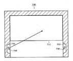
또한, 예를 들어 도 39에 도시한 바와 같이, 촬상 카메라(706)는 해당 촬상 카메라(706)가 설치되어 있는 측과는 반대측의 문(703)이 열린 상태에서, 해당 문(703)에 설치되어 있는 도어 포켓(705)을 촬상 가능한 위치에 설치하면 좋다.39, the
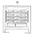
또한, 예를 들어 도 40에 도시한 바와 같이, 오목부(702)내에서 촬상 카메라(706)의 설치 위치와 조명용 LED(707)의 설치 위치를 상하 방향을 따라서 열의 형상으로 배치하는 구성으로 해도 좋다. 또한. 예를 들면 도 41에 도시한 바와 같이, 오목부(702)내에서 촬상 카메라(706)의 설치 위치와 조명용 LED(707)의 설치 위치를 가로 방향으로 어긋나게 해도 좋다.40, the mounting position of the
또한, 예를 들어 도 42에 도시한 바와 같이, 인출 가능한 용기(720)를 고내에 설치하고, 촬상 카메라(706)는 용기(720)가 인출된 상태(도면 중, 파선으로 나타냄)에서 해당 용기(720)의 측면에 대향하는 위치에 설치하는 구성으로 해도 좋다. 이 경우, 용기(720)를 촬상하기 위한 전용의 촬상 카메라(706) 및 조명용 LED(707)를 설치하도록 해도 좋다. 또한, 예를 들어 도 43에 도시한 바와 같이 인출 가능한 복수의 용기(721, 722)를 고내에 설치하고, 촬상 카메라(706)는 이들 용기(721, 722)의 어떤 것도 촬상 가능한 위치에 설치하는 구성으로 해도 좋다. 이 경우, 각 용기(721, 722)를 각각 촬상하기 위한 전용 촬상 카메라(706) 및 조명용 LED(707)를 설치하도록 해도 좋다. 또한, 용기의 수는 2개에 한정되는 것이 아니라, 3개 이상의 복수의 용기를 고내에 설치해도 좋다. 이 경우, 촬상 카메라(706)는 모든 용기를 촬상 가능한 위치에 설치하면 좋다.42, the
또한, 예를 들어 도 44에 도시한 바와 같이, 촬상 카메라(706)는 고내에 설치된 선반(711)의 전단부보다 후방측에 설치해도 좋다. 이 경우, 당연히 촬상 카메라(706)는 문에 설치되어 있는 도어 포켓(705)보다 뒤쪽에 설치된다. 이 경우, 복수의 촬상 카메라(706)는 상하로 늘어선 선반(711,711) 사이에 설치하면 좋다. 이 경우, 선반(711)의 상측에 위치하는 촬상 카메라(706)는 그 선반(711)의 상측을 촬상 가능한 상부 전용 촬상 카메라(상부 전용 촬상 수단의 일례)로서 기능하고, 선반(711)의 하측에 위치하는 촬상 카메라(706)는 그 선반(711)의 하측을 촬상 가능한 하부 전용 촬상 카메라(하부 전용 촬상 수단의 일례)으로서 기능한다.For example, as shown in Fig. 44, the
또한, 용기(720)의 상측에 설치되는 적어도 1개의 선반(711)을, 예를 들면 투명한 수지로 구성하고, 투명한 선반으로서 구비하는 구성으로 해도 좋다. 이 구성에 따르면, 이 투명 선반보다 상측에 위치하는 적어도 1개의 촬상 카메라(706)는 이 투명 선반을 통하여, 용기(720)의 내부를 촬상 가능하게 된다.At least one
또한, 오목부(702) 내부에, 고내의 광량을 검지하는 광량 검지 센서를 실장하는 광량 검지용 기반을 구비하고, 촬상 카메라(706)를 그 광량 검지용 기반에 실장하도록 구성해도 좋다. 또한, 광량 검지 센서를 고내의 조도를 검출하는 조도 센서로서 이용함으로써, 광량 검지용 기반을 조도 검지용 기판으로 간주할 수 있다. 이 경우, 촬상 카메라(706)를, 그 조도 검지용 기반에 실장하도록 구성해도 좋다. 또한, 이러한 종류의 기판류는 카드 형상 또는 판 형상을 이루고 있다. 그리고, 이러한 종류의 기판류는 그 양단이 예를 들어, 오목부(702) 내에 설치된 슬릿 형상의 피부착부에 파고들어 오목부(702)내에 부착되어 있다.It is also possible to provide a light amount detecting base for mounting a light amount detecting sensor for detecting the amount of light in the inside of the
또한, 오목부(702)의 저장실측을 덮는 방호 커버(710)에는 촬상 카메라(706)용 및 도시하지 않는 수광부용으로, 각각 개별적으로 촬상용 구멍부 및 수광용 구멍부를 설치해도 좋다. 이 경우, 촬상용 구멍부는 시야에 걸리지 않도록 그 벽부를 비스듬히 형성해도 좋다. 또한, 수광용 구멍부에는 집광용 렌즈나 투명한 커버나 카메라용 렌즈를 설치하거나, 촬상용 구멍부에는 카메라 장치를 덮는 투명한 커버를 설치하면 좋다. 이들 렌즈나 커버는, 사람의 손의 유분이나 야채 찌꺼기 등의 오염물질이 부착되지 않도록, 방호 커버(710)의 표면이나 저장실을 구성하는 내부상자 표면에 노출되지 않도록 방호 커버(710)의 표면보다 안쪽의 오목부(702)측에 배치하면 좋다. 또한, 렌즈나 커버에 습기에 의해 결로된 경우에 결로된 물(물방울)이 흐르기 쉽고, 저장실 내에 배출할 수 있도록, 각 구멍부를 하방으로 경사지게 하거나, 가는 홈을 설치하여 모세관 현상에 의해 배출할 수 있도록 해도 좋다.It should be noted that the
또한, 촬상 카메라(706)는 수광부와는 다른 위치이며, 조사 수단으로부터 조사되는 광량이 억제되는 문이나 측면 등의 위치에 설치되어 있다. 그와 같은 위치에서는 촬상 카메라(706)에 대해서 조사 수단으로부터 조사된 빛의 입사가 억제되므로 역광이 될 우려를 감소시킬 수 있다.The
또한, 촬상시의 조명용 촬상 조명 수단과 촬상시의 조사용 조사 수단을 설치하고, 조사 수단은 촬상 조명 수단과는 조사하는 광량 및 색을 다르게 하는 구성으로 해도 좋다. 이에 의해, 촬상 조명 수단이 점등되었을 때에 수광부가 오검지할 우려를 방지할 수 있다.It is also possible to provide illumination illumination means for imaging and illumination illumination means for imaging, and the illumination means may have a different illumination amount and color from the illumination illumination means. Thereby, it is possible to prevent a possibility that the light receiving unit is erroneously detected when the imaging illumination means is turned on.
이 경우 색이 다른 조사 수단은 촬상 카메라(706)로 촬상할 때에는 점등하지 않도록 하면 좋다. 이에 의해, 화상이 파래지는 부자연스러운 상태에서 촬상되는 것을 방지할 수 있다. 또한, 백색과 다른 청색 LED등의 제1 발광 수단(조사 수단)으로서는 그 파장이 거의 400nm의 청색의 광을 필터나 벽 등에 설치된 촉매에 조사함으로써 여기시켜 탈취·제균을 실시하는 가시광 촉매 장치나, 공기 절연 파괴함으로써 청백색으로 발광하여 이온, 라디컬(활성종), 오존을 발생시키는 코로나 방전 장치, 대향 전극과 액체를 방전 전극으로 하여 고전압을 인가하고 OH라디컬을 함유하는 대전 미립자수를 발생시키고 전극이 청백색으로 빛나는 정전 무화 장치 등의 공기 절연 파괴 장치나, 저장실 내에 구비되고 사용자가 냉장고의 제어를 실시하는 억압식 등의 조작부의 표시를 하는 녹색이나, 적색, 오렌지 등의 LED등의 표시 수단이 포함된다. 이 제1 발광 수단은 미리 프로그램에 기억된 소정 조건에서 발광하는 것이고, 촬상하는 경우에는 설정 조건에서 발광하는 제어를 무효화함으로써 (즉, 카메라의 촬상을 우선하고, 카메라로 촬상할 때에는 설정조건이 성립되어 있었다고 해도 발광하지 않도록 함으로써) 화상에 불필요한 빛이 들어가지 않게 되고, 깨끗하게(선명하게) 촬상할 수 있다. 이 억압식의 조작부(고내 조작부)는 오목부(702)내에 택트 스위치를 구비하고, 방호 커버(710)에 조작 버튼을 설치하면 좋다.In this case, the irradiating means with different colors may not be turned on when the
또한, 가시광 촉매 장치, 코로나 방전 장치, 정전 무화 장치 등을 구비한 구성으로 해도 좋다. 가시광 촉매 장치, 코로나 방전 장치, 정전 무화 장치 등은 소정 시간마다 구동하거나 댐퍼의 개폐에 연동하여 구동되는 제어로 하는 조건을 설정 가능하며, 고내 조작부의 조작에 기초하는 표시 수단의 발광은 조작의 ON/OFF를 조건으로 하여 제어하는 것이 가능하다. 또한, 냉장실 저면에 구비된 인출식 칠드룸 등을 비추는 제2 발광 수단인 백색이나 다른 색의 LED는 좌우 상하의 벽이나 문과 다른 위치이고 공간의 중앙에 있으므로, 좌우 상하에 배치된 카메라의 화상에 비쳐 들어가기 쉬워 역광이 될 가능성이 있다. 그 때문에, 동일하게 카메라의 촬상 타이밍에는 무효 또는 OFF로 하거나 촬상 중에는 점등을 일단 중지하고 촬상이 종료된 후에 점등시키는 등의 제어를 실시하면 좋다.It is also possible to provide a visible light catalyst device, a corona discharge device, an electrostatic atomizer, and the like. It is possible to set conditions such as a visible light catalytic device, a corona discharge device, an electrostatic atomizer, etc. to be driven at predetermined time intervals or in conjunction with opening and closing of the damper, and the light emission of the display means based on the operation of the in- / OFF can be controlled. Further, the LEDs of white or other colors, which are the second light emitting means for illuminating the draw-out chillrooms provided on the bottom of the refrigerating compartment, are located at the center of the space and at positions different from the walls and doors of the upper and lower left and right and lower, It is easy to enter and there is a possibility of backlighting. For this reason, it is preferable to perform the control such that the imaging timing of the camera is disabled or turned off in the same manner, or the lighting is temporarily stopped and the imaging is ended after the imaging is completed.
또한, 가시광 촉매는 촬상용 구멍부에서 촬상 카메라(706)를 덮는 투명 커버나, 카메라 장치의 렌즈, 또한 오목부(702)를 덮는 방호 커버(710)의 표면에 도포하여 친수화 수단으로서 기능시켜도 좋다. 카메라의 렌즈나 투명 커버 등은 저장고에 노출 등 되어 있는 경우에는 결로 등으로 흐려져, 촬상한 화상이 희미해진다는 과제가 있지만, 청색 LED 등의 제1 발광 수단인 촉매를 여기 가능한 가시광 발생 수단을 오목부(702)내, 또는 오목부(702) 밖에 설치하여 광촉매에 조사함으로써, 렌즈, 커버 등의 표면이 공기 중의 수분과 활성하여 OH라디컬(친수성 수단)의 작용에 의해 친수화한다. 그러면, 렌즈나 커버가 결로된 경우에도 물이 결합하기 쉬워지므로 표면이 물의 얇은 막이 되기 쉽고, 요철의 물방울이 생기기 어려워짐으로써 광의 난반사를 방지할 수 있으며, 따라서 표면을 흐리기 어렵게 할 수 있다. 따라서, 카메라 장치의 촬상 방향에 위치하는 렌즈나 투명 커버에 친수성 수단이 생성되는, 또한 접촉함으로써 카메라에 의한 촬상한 화상도 희미해지지 않고 명확하게 촬상할 수 있다. 그리고, 이 광촉매는 특정 파장의 광이 조사됨으로써 공기 중의 세균을 제균하거나 공기 중의 냄새 성분(유기 물질 등)을 산화나, 분해 등을 하여 탈취할 수 있는 촉매이고, 공기 중의 성분을 활성화(이온화나 라디컬화)하고 이에 기초하여 제균하거나 탈취하거나 할 수도 있다. 광촉매로서는 산화은이나 산화 티탄을 이용할 수 있어 산화은(인산 지르코늄은을 포함)에는 광의 파장은 약 400nm~580nm정도의 가시광의 청색 영역을 이용하고, 산화티탄에는 광의 파장은 380nm을 조사 가능한 발광 다이오드의 광원을 이용하면 좋다.The visible light catalyst may be applied to the surface of the transparent cover covering the
또한, 상기 정전 무화 장치로서는 방전극의 선단은 뾰족하고, 대극과의 사이에 -6kV정도의 전압을 인가하고, 방전극에 금속제의 부재를 사용하여 금속제의 부재를 냉각함으로써 공기 중의 수분의 결로수를 얻고, 그 결로수를 정전 무화함으로써 입자직경이 나노 미터 사이즈(입자직경의 분포는 3~50nm)의 대전 미립자 수를 얻을 수 있고, 방전극의 선단에 청백색 광이 발광하여, 전압을 인가하면서도 발광이 ON/OFF하고, 소정 간격(예를 들면 5초 간격)으로 단속적으로 반복된다. 또한, 정전 무화 장치의 구동도 소정 시간마다 ON/OFF를 반복하는 제어로 하면 좋다. 또한, 정전 무화 장치는 방전광이 비치기가 어려워지도록 분출구를 구비하는 커버 내에 수납해도 좋고, 정전 무화 장치를 천장에 덕트 형상의 커버 내에 배치하고 촬상 카메라(706)를 천정 이외의 대향하지 않는 문이나, 좌우 측벽 등에 배치함으로써 방전광이 비치기 어려워지는 효과가 있다. 또한, 정전 무화 장치가 배치된 저장실과 다른 저장실에 촬상 카메라(706)를 배치해도 동일한 효과가 있다. 또한, 미스트를 발생시키면 저장실 내가 안개 형상이 되어 카메라로 촬상한 경우에 안개 때문에 비치기 어려워진다는 과제가 있지만, 미스트의 입자직경을 나노 미터 크기의 미립자수로 함으로써 안개 형상이 되지 않고 깨끗한 화상을 촬상할 수 있다. 또한, 나노 미터 크기의 대전 미립자수(OH라디컬 포함)이면 카메라 장치의 렌즈, 커버에 접촉해도 결로도 되기 어렵고 흐려지기 어려운 효과도 있다.In the electrostatic atomizer, the tip of the discharge electrode is sharp, a voltage of about -6 kV is applied between the discharge electrode and the counter electrode, and a metal member is used for the discharge electrode to cool the metal member, , The number of charged fine particles having a particle size of nanometer size (the particle diameter distribution is 3 to 50 nm) can be obtained, and blue white light is emitted to the tip of the discharge electrode, / OFF, and is intermittently repeated at a predetermined interval (for example, at intervals of 5 seconds). In addition, the operation of the electrostatic atomizer may be controlled so as to be repeatedly turned on / off at predetermined time intervals. In addition, the electrostatic atomizer may be housed in a cover provided with an air outlet so that the discharge light is difficult to be emitted. The electrostatic atomizer may be disposed in a ceiling-like duct-like cover, and the
또한, 예를 들어 도 45에 도시한 바와 같이 촬상 카메라(706)는 배터리(730) 등과 함께 유닛화되어 촬상 유닛(731)을 구성하고, 이 촬상 유닛(731)을 예를 들면 오목부(702)에 설치한 피부착부 등에 착탈 가능하게 구성해도 좋다. 이 경우, 촬상 유닛(731)은 오목부(702)내에 설치된 전원 커넥터(732)를 통하여 냉장고(700)의 전원 계통에 접속되도록 이루어져 있다. 또한, 도시는 않지만 도어 포켓(705)등에 전원 커넥터를 설치하고, 촬상 유닛(731)을 도어 포켓(705)에 착탈 가능하게 설치하는 구성으로 해도 좋다. 또한, 이 오목부(702)에 예를 들면 도 13, 도 14에 예시하는 유지부(202)나, 예를 들면 도 19에 예시하는 냉장고용 홀더(400)의 유지부(401)등의 피부착부를 설치함으로써, 간단히 촬상 유닛(731)을 설치 가능해진다. 그리고 전원 커넥터는 움직이는 것이 가능한 선 형상의 것으로 구성하면 좋고, 예를 들어 USB단자 등으로 구성해도 좋다. 또한, 이른바 수(雄)형 단자를, 카메라에 설치한 이른바 암(雌)형 단자에 삽입함으로써, 피부착부로서 삽입 분리 가능하게 구성해도 좋다. 또한, 이른바 암형 단자에 카메라에 설치한 이른바 수형 단자를 삽입하는 구성으로 해도 좋다. 또한, 급전부로서는, 이동 가능한 선 형상의 것으로 구성해도 좋고, 고정되어 이동 불가능한 것으로 구성해도 좋다.45, the
또한, 예를 들어 도 46에 도시한 바와 같이 고내의 속면의 좌우 양측에 급풍구(740)를 설치하고, 이들 급풍구(740)로부터 공급되는 바람이, 방호 커버(710)의 표면(고내측의 면)을 따라서 흐르도록 구성해도 좋다. 이와 같이 바람이 방호 커버(710)의 표면을 따라서 흐름에 의해, 해당 방호 커버(710)의 결로를 방지할 수 있다.
As shown in Fig. 46, for example, air supply holes 740 are provided on both left and right sides of the inner surface of the hood, and the air supplied from these air supply holes 740 is blown to the surface of the protective cover 710 (I.e., the surface of the substrate). As described above, the wind can flow along the surface of the
또한, 예를 들어 중앙에 위치하는 냉기 덕트에 좌우를 향하여 개구하는 분사구를 설치하고, 그 분사구로부터 방호 커버(710)를 향하여 냉기를 흘리는 구성으로 해도 좋다.Further, for example, it is also possible to provide a jet port that opens to the right and left in a cool air duct located at the center, and cool air is allowed to flow from the jet port toward the
또한, 예를 들어 도 47에 도시한 바와 같이, 고내에 설치되는 선반 중 적어도 하나를, 고내를 상하방향으로 이동 가능한 가동선반(750)으로서 설치해도 좋다. 이 경우, 가동 선반(750)의 좌우 양단의 하부에는 상기 가동선반(750)을 상하 방향으로 이동시키기 위한 이동기구부(751)가 설치되어 있다. 이 이동 기구부(751)는, 예를 들어 도시하지 않은 조작 손잡이를 조작함으로써 내부의 와이어를 이동시키고, 이 와이어의 이동에 따라 가동선반(750)을 상하로 이동시키는 구성이다. 또한, 가동선반(750) 중 적어도 좌우 양단부에는 이동 기구부(751)을 상방으로부터 덮어 가리는 불투명부(750a)가 설치되어 있다. 이 불투명부(750a)는 예를 들어 불투명한 부재를 부착함으로써 또는 불투명한 도료를 도포함으로써 실현할 수 있다.47, at least one of the shelves provided in the cabinet may be provided as a
이 경우, 촬상 카메라(706)는 가동선반(750)을 상한 높이부터 하한 높이까지의 어느 위치로 이동시킨 경우에도, 그 가동선반(750) 상을 촬상 가능한 위치에 설치하면 좋다. 즉, 촬상 카메라(706)는 적어도 가동선반(750)의 상한 높이보다 높은 위치에 설치하고, 그 촬상 방향을 위에서 아래를 향하여 비스듬히 향하는 방향으로 설정하면 좋다.In this case, the
또한, 예를 들어 도 48에 도시한 바와 같이, 촬상 카메라(706)를 가동선반(750)의 상방이 되는 고내의 천정면에 설치해도 좋다. 이 구성에 따르면, 가동선반(750)을 상한 높이에서 하한 높이까지의 어느 위치로 이동시킨 경우에도 그 가동반(750)상을, 상방으로부터 촬상 카메라(706)에 의해서 촬상할 수 있다. 또한, 불투명부 (750a) 이외의 투명한 부분(투명부)을 통하여, 하방의 선반의 수용물을 촬상하는 것도 가능하다.For example, as shown in Fig. 48, the
또한, 본 실시형태에 예시한 구성은 어느 구성도 냉장고에 설치되는 저장고, 예를 들면 냉장실, 냉동실, 야채실, 칠드실 등에 적용할 수 있다.In addition, any of the structures exemplified in this embodiment can be applied to a storage room installed in a refrigerator, for example, a refrigerator, a freezer, a vegetable room, a chilled room, and the like.
(제4 실시형태)(Fourth Embodiment)
이하, 제4 실시형태에 대해서, 도 53 내지 도 64를 참조하면서 설명한다. 또한, 제1 실시형태와 공통되는 부위는 동일한 부호를 붙이고 그 상세한 설명은 생략한다. 또한, 촬상 타이밍에 대해서는 상기한 각 실시형태에서 예시한 것을 적절하게 채용하면 좋다.Hereinafter, the fourth embodiment will be described with reference to Figs. 53 to 64. Fig. Parts common to those of the first embodiment are denoted by the same reference numerals, and a detailed description thereof will be omitted. As for the imaging timing, those exemplified in the above-described embodiments may be appropriately employed.
도 53에 도시한 바와 같이, 본 실시형태의 냉장고(1)는 촬상 수단으로서의 카메라 유닛(1000)을 구비하고 있다. 이 냉장고(1)는 제1 실시형태와 동일하게, 가전 네트워크 시스템(100)(도 1참조)에 접속되어 있다. 이 경우, 냉장고(1)는 제1 실시형태와 같이 무선 통신 방식으로 가전 네트워크 시스템(100)에 접속해도 좋고 유선 통신 방식으로 가전 네트워크 시스템(100)에 접속해도 좋다. 본 실시형태에서는 유선 통신 방식으로서 냉장고(1)로의 전력을 공급하는 전력선을 이용하여 통신을 실시하는 전력선 통신(PLC:Power Line Communication)을 채용하고 있다. 이하, 카메라 유닛(1000)의 부착 위치에 대해서 몇 가지의 구체예와 함께 설명한다.As shown in Fig. 53, the
<구체예 1>≪ Specific Example 1 &
구체예 1의 카메라 유닛(1000)은 냉장고(1)의 문에 설치되어 있다. 이 카메라 유닛(1000)은 예를 들면 냉장실(3)의 고내의 중앙을 촬상 가능한 위치에 설치되어 있고, 구체적으로는 촬상 대상이 되는 냉장실(3)(저장고)을 개폐하는 우측 문(3b)에서, 해당 냉장실(3)의 상하 방향 및 좌우 방향에서ㅡ이 거의 중앙의 위치에 대응하도록 설치되어 있다. 이 카메라 유닛(1000)은 도 54(A), (B)에 도시한 바와 같이 그 외형이 대체로 직방체 형상으로 형성되어 있고, 카메라 케이스(1001)(보호 케이스에 상당함)와 저판(1002)으로 둘러 쌓인 공간에 카메라 모듈(1003)(촬상 모듈에 상당함)이 수용된 구성으로 되어 있다.The
또한, 카메라 유닛(1000)에는 냉장고(1)측과의 사이를 접속하는 케이블(1004) 및 카메라 유닛(1000)을 고정하기 위한 플랜지부(1005)가 설치되어 있다. 케이블(1004)은 냉장고(1)측으로부터 전원 공급, 카메라 유닛(1000)에 대한 촬상 지시의 전달, 및 촬상된 화상 데이터 취득에 사용된다. 이 카메라 유닛(1000)은 플랜지부(1005)에 의해서 문(3b)의 고내측에 부착되어 있다. 그 때문에 구체예 1 및 후술하는 구체예 2~4의 경우 접속 케이블(1004)은 문(3b)의 내부에 배선되고 문의 힌지부를 경유하여 냉장고(1)의 주제어부(30)(도 4참조)에 접속되어 있다.The
카메라 모듈(1003)은 도 55에 도시한 바와 같이 CCD센서나 CMOS센서 등을 촬상 소자(1010) 및 그 주변 회로를 구성하는 회로 부품(1011)등이 탑재된 기판(1012)과, 그 기판(1012)에 설치되어 있는 렌즈 유닛(1013)으로 구성되어 있다. 본 실시형태의 촬상 소자(1010)는 장방형으로 형성되어 있으며, 그 길이 방향이 카메라 유닛(1000)의 길이 방향(도 54의 도시 상하 방향)과 일치한다. 이 기판(1012)에는, 촬상 소자(1010)에 대응한 위치에 렌즈 홀더(1014)가 설치되어 있고, 그 렌즈 홀더(1014)의 내주면은 암나사로 되어 있다. 한편, 렌즈 유닛(1013)은 기판(1012)측의 단부가 수나사로 되어 있고, 렌즈 홀더(1014)에 나사 삽입됨으로써, 촬상 소자(1010)까지의 거리가 조정된 상태로 부착되어 있다.The
이 렌즈 유닛(1013)는 복수매, 예를 들면 본 실시형태에서는 3매의 렌즈(1015)를 구비하고 있고, 각 렌즈(1015)는 예를 들면 수지 재료 등으로 형성된 본체부내에 유지되어 있다. 카메라 유닛(1000)은 이들 3매의 렌즈(1015)에 의해 약 120도의 시야각이 확보되어 있고 고내를 광각으로 촬상하는 것이 가능해져 있다. 또한, 렌즈 유닛(1013)에는 적외 컷 필터(1016)가 설치되어 있고, 촬상 소자(1010)에서 검출하는 광을 대략 가시광의 범위로 한정하고 있다. 이 때문에 카메라 유닛(1000)은 고내를 컬러로 촬상할 때 선명한 색채로 촬상할 수 있다. 렌즈(1015)의 매수 등은 일례이며, 필요한 시야각에 따라 적절히 선택하면 된다.This
또한, 카메라 유닛(1000)은 도 53(B)에 도시한 바와 같이 카메라 케이스(1001)내가 예를 들면 우레탄 수지나 에폭시 수지 등의 포팅재(1017)에 의해서 카메라 모듈(1003)마다 포팅되어 있다. 또한, 도 55에 도시한 바와 같이, 렌즈 유닛(1013)에는 그 외주측에 O링(1018)이 설치되어 있으며, 그 O링(1018)에 의해서 렌즈 유닛(1013)과 카메라 케이스(1001)의 내면과의 사이가 밀봉되어 있다. 또한, 도 55에서는 포팅재(1017)의 도시를 생략하고 있다.53 (B), the
이 때문에, 렌즈 유닛(1013)의 전면측으로부터 물이나 습기가 카메라 케이스(1001)내에 침투하는 것이 방지되어 있다. 또한, 카메라 케이스(1001)의 저판 (1002)측도 접속 케이블(1004)이 관통하고 있는 부위를 포함하여 밀봉된 상태로 되어 있다. 즉, 카메라 유닛(1000)은 전체적으로 방수 구조 또는 방적(防滴) 구조로 되어 있고, 또한 내부의 카메라 모듈(1003)도 결로 등으로부터 보호되고 있다.Therefore, water or moisture is prevented from penetrating the
이 카메라 유닛(1000)은 도 56(A)에 도시한 바와 같이 우측 문(3b)의 내판(14)에 부착되어 있다. 또한, 카메라 유닛(1000)은 문(3b)이 폐쇄된 상태에서의 시야가 고내측이 되도록 부착되어 있다. 이 때문에 카메라 유닛(1000)은 우측문(3b)이 폐쇄된 상태에서는 냉장실(3)을 정면으로부터, 또한 상하 방향 및 좌우 방향의 거의 중앙으로부터 촬상하는 것이 가능해져 있다. 즉, 카메라 유닛(1000)은 사용자가 냉장고(1)를 사용할 때와 동일한 시야에서 고내를 촬상할 수 있다. 이 때, 카메라 유닛(1000)에 인접하여 배치되어 있는 도어 포켓(9b)은 제1 실시형태와 동일하게 절개부(9b1)가 설치되어 있고, 카메라 유닛(1000)의 시야를 크게 가리지 않도록 되어 있다.This
또한, 카메라 유닛(1000)은 도 56(B)와 같이 길이 방향이 상하가 되도록 세로방향으로 부착되어 있다. 이 때문에, 카메라 유닛(1000)내의 촬상 소자(1010)도, 그 길이 방향이 세로방향으로 되어 있다. 이에 의해, 상하 방향과 좌우 방향에서 그 크기가 다른 대략 직방체 형상으로 형성되고, 세로로 긴 공간이 되어 있는 냉장실(3)을, 세로로 길게 촬상할 수 있다. 즉, 세로로 길게 배치된 촬상 소자(1010)의 촬상 범위를 유효하게 활용하면서 고내를 촬상할 수 있다.56 (B), the
<구체예 2>≪ Specific Example 2 &
구체예 2의 경우, 카메라 유닛(1000)은 도 57에 도시한 바와 같이, 우측 문(3b)의 내판(14)측에 설치되어 있는 오목부(1020)에 부착되어 있다. 또한, 구체예 2에서도, 카메라 유닛(1000)은 세로방향으로 부착되어 있다. 이 오목부(1020)는 카메라 유닛(1000) 전체를 수용할 수 있을 정도의 크기로 형성되어 있고, 그 오목부(1020)에 수용되어 있는 카메라 유닛(1000)은 내판(14)보다 고내 측으로 돌출되지 않도록 되어 있다. 이 때문에, 우측 문(3b)의 최하단의 도어 포켓(10b)(도 53참조)에 페트병 등을 출입할 때, 카메라 유닛(1000)에 접촉되는 것이 방지된다.57, the
또한, 카메라 유닛(1000) 전체가 오목부(1020)에 수용되어 있으므로, 사용자가 손을 접촉할 가능성이 적어지고, 렌즈(1015)가 오염될 우려를 감소시킬 수 있다.Further, since the
또한, 카메라 유닛(1000)은, 그 위치가 상기한 구체예 1 보다 고외측, 즉 냉장고(1)의 전방측으로 어긋나 있다. 이 때문에, 냉장실(3)내를 보다 큰 시야에서 촬상할 수 있다.In addition, the
이 경우, 오목부(1020)의 개구측에, 예를 들면 내판(14)과 하나의 면이 되는 위치에, 예를 들면 아크릴 등의 투명한 커버 부재 등을 설치해도 좋다. 이에 의해, 렌즈(1015) 등에 오염물질이 부착되는 것이나, 오목부(1020)에 먼지 등이 고이는 것을 방지할 수 있다.In this case, for example, a transparent cover member such as acrylic may be provided on the opening side of the
<구체예 3>≪ Specific Example 3 &
구체예 3의 경우 카메라 유닛(1000)은 도 58에 도시한 바와 같이 우측 문(3b)의 내판(14)내에 배치되어 있다. 또한, 구체예 3도 카메라 유닛(1000)은 세로방향으로 부착되어 있다. 이 경우, 카메라 유닛(1000)은 그 렌즈면만이 냉장실(3)측에 노출된 상태가 되어 있다. 이 때문에, 구체예 2와 동일하게 도어 포켓(10b)에 페트병 등을 출입할 때 카메라 유닛(1000)이 방해가 되는 것이 방지된다.In the specific example 3, the
이들 구체예 1~3과 같이 카메라 유닛(1000)을 부착함으로써, 도 59(A)에 도시한 바와 같이 사용자가 냉장고(1)를 사용할 때의 시점(視點)과 동일하게 냉장고(1)의 정면측에서 고내를 촬상할 수 있고, 가전 네트워크 시스템(100)을 통하여 통신 단말(103) 등에서 촬상한 화상을 표시함으로써, 원격지로부터 고내를 확인할 수 있다.By attaching the
<구체예 4><Specific Example 4>
구체예 4의 경우, 카메라 유닛(1000)은 좌측 문(3a)에 설치되어 있는 칸막이 (17)(도 53 참조)에 부착되어 있다. 이 세로 칸막이는 도 60(A),(B)에 도시한 바와 같이 좌측 문(3a)의 힌지부(3d)와 반대측의 단부에 설치되어 있고, 회전 기구(17a)에 의해서 도 60(A)에 도시한 바와 같이 문(3a)이 개방되어 있는 상태와 도 60(B)에 도시되어 있는 바와 같이 문(3a)이 폐쇄되어 있는 상태로 그 방향이 변화된다. 이 세로 칸막이는 좌우 여닫이식 문(이른바 프렌치 도어)의 좌우 방향의 거의 중앙, 즉 냉장실(3)의 거의 중앙부에 위치하고 있다. 그리고 좌측 문(3a)과 우측 문(3b)이 폐쇄된 상태에서는 도 61(A)에 도시한 바와 같이 개스킷(1030)에 의해서 고내와 고외가 밀봉되어 있다.In the concrete example 4, the
카메라 유닛(1000)은 도 61(A),(B)와 같이, 단열재(1031)가 충전되어 있는 세로 칸막이(17)의 내부에서 부착판(1032)에 세로방향으로 부착되어 있다. 이 카메라 유닛(1000)은 세로 칸막이(17)의 상하 방향의 거의 중앙에 배치되어 있다. 이 때문에, 구체예 4에서도 카메라 유닛(1000)는 냉장실(3)의 상하 방향 및 좌우 방향의 거의 중앙으로부터 고내를 촬상 가능하게 되어 있다. 그리고, 상기한 바와 같이 세로 칸막이(17)가 회전하므로, 좌측 문(3a)이 개방된 상태에서는 도 60(A)와 같이 카메라 유닛(1000)이 좌측 문(3a)과 평행이 되도록, 또한 개방된 측과 반대측이 된다. 이에 의해, 좌측 문(3a)이 개방됐을 때 사용자가 카메라 유닛(1000)의 렌즈면에 접촉되는 것이 방지되어 있다.The
그리고, 좌측 문(3a)이 폐쇄된 상태에서는 도 60(B)와 같이 카메라 유닛(1000)이 고내 측을 향하므로, 도 62에 도시한 바와 같이 정면측 또한 거의 중앙 부근으로부터 고내를 촬상할 수 있다. 이 경우, 도어 포켓(9a)이 카메라 유닛(1000)의 시야를 가릴 듯하면, 도어 포켓(9b)과 동일한 절개부를 도어포켓(9a)에 설치해도 좋다.When the
이러한 구체예 4의 경우에도 상기한 구체예 1~3과 동일하게 도 59(A)에 도시한 바와 같이 고내를 촬상할 수 있다.In the case of the fourth specific example as well, as shown in Fig. 59 (A) in the same manner as the first to third embodiments described above, it is possible to pick up the inside of the image.
<구체예 5>≪ Specific Example 5 >
구체예 5의 경우, 도 63에 도시한 바와 같이 카메라 유닛(1000)은 냉장실(3)의 측벽(3c)에 설치되어 있는 오목부(1040)에 부착되어 있다. 구체예 5의 경우 카메라 유닛(1000)은 좌우의 측벽(3c)에 각각 부착되어 있다. 또한, 한쪽의 측면(3c)에만 카메라 유닛(1000)을 부착하는 구성이어도 좋다.63, the
오목부(1040)는 측벽(3c)에서 전방측 즉 문측에 설치되어 있고, 카메라 유닛(1000)을 부착하기 위한 부착면(1041)이, 측벽(3c)에 대해서 경사진 형상으로 형성되어 있다. 구체예 5의 경우, 오목부(1040)는 단면으로 보았을 때 대략 삼각형으로 형성되어 있다. 이에 의해, 카메라 유닛(1000)을 부착했을 때, 그 시야가 냉장실(3)의 거의 중앙을 향하게 된다.The
그리고, 구체예 5에서는 좌우의 2방향으로부터 고내를 촬상하기 위해, 한쪽의 카메라 유닛(1000)에서는 식재료 등으로 가려진 부분을, 다른쪽의 카메라 유닛(1000)으로부터 촬상할 수 있다. 이에 의해, 식재료 등에 방해받지 않고 고내 전체를 촬상할 수 있게 되어, 고내를 보다 상세하게 확인할 수 있다. 또한, 2방향으로부터 촬상한 영상을 합성하여 입체 화상을 생성함으로써, 고내를 입체적으로 표시시킬 수도 있다.In the concrete example 5, a portion covered with food or the like in one
또한, 측벽(3c)에 카메라 유닛(1000)을 부착하고 있으므로, 유선식 카메라 유닛(1000)에서 측벽(3c)을 이용하여 접속 케이블(1004)을 배선하는 것이 가능해지고, 예를 들면 냉장고(1)의 배면측에 설치되어 있는 주제어부(30)(도 4참조)까지 용이하게 배선 처리할 수 있다.In addition, since the
<구체예 6>≪ Specific Example 6 >
구체예 6에서는 도 64(A)와 같이 카메라 유닛(1000)에 조명 수단으로서의 LED조명(1050)이 설치되어 있다. 이 카메라 유닛(1000)은 전면측이 적어도 LED조명(1050)에 대응하는 위치가 투명해진 된 보호 커버(1051)에 의해서 덮여져 있다. 또한, 카메라 유닛(1000)은 구체예 1~5의 카메라 유닛(1000)과 동일하게 카메라 케이스(1001)내가 포팅재(1017)에 의해 포팅되어 있다.In the specific example 6, the
이 카메라 유닛(1000)은 본 실시형태에서는 그 전면에 설치되어 있는 보호 커버(1051)와 부착면(1060)과 하나의 면이 되도록 배치되어 있다. 즉, 카메라 유닛(100)은 수납부에 수납되어 있다. 이 부착면(1060)은 예를 들면 문의 내판(14), 세로 칸막이(17), 측벽(3c) 등에 상당한다. 이 상태에서 렌즈 유닛(1013)의 최전면은 부착면(1060)보다 전방에 위치하고 있다.In this embodiment, the
LED조명(1050)은 도 64(B)에 도시한 바와 같이, 카메라 케이스(1001)내에서 촬상 소자(1010)(도 55참조)와는 전후 방향으로 다른 위치에 배치되어 있다. 구체적으로는 LED조명(1050)은 촬상 소자(1010)보다 전방에 배치되어 있다. 본 실시형태의 경우, 기판(1012)에 촬상 소자(1010)를 실장하고, 그보다 전방에 배치된 LED기판(1052)에 LED조명(1050)을 실행함으로써 그 위치를 다르게 하고 있다.The
이 LED조명(1050)은 카메라 유닛(1000)의 전면에 가까운 위치에 배치되어 있고, LED조명(1050)으로부터 조사된 광이 카메라 케이스(1001) 내에서 렌즈 유닛(1013)이나 촬상 소자(1010)에 직접적으로 입사ㅗ디는 것이 방지되어 있다. 또한, LED조명(1050)은 전방을 향하여 확대된 개구벽(1053)에 둘러싸여 있고, 렌즈 유닛(1030)의 전방면 보다 후방에 위치하고 있다. 그리고, 렌즈유닛(103)의 최전면이 부착면(1060)보다 전방에 위치되어 있는 점에서, LED의 전방면을 보호하고 있는 보호 커버(1051)에 빛이 반사되었다고 해도 그 빛이 렌즈 유닛(1013)에 직접적으로 입사되지는 않는다.The
이와 같은 구성의 카메라 유닛(1000)은 구체예 1~5에 예시한 위치에 부착함으로써, 고내 조명(13) 등을 점등하지 않아도 LED조명(1050)을 점등시킴으로써 고내를 촬상할 수 있다.By attaching the
또한, 카메라 유닛(1000)은 보호 커버(1051)가 부착면(1060)보다 내측(후방)에 위치하도록 배치되어 있어도 좋다. 그 경우, 렌즈 유닛(1013)의 최전방면이 부착면(1060)과 하나의 면이 되도록 배치해도 좋고, 부착면(1060)보다 내측에 위치하도록 배치해도 좋다. 또한, 렌즈 유닛(1013)의 최전방면이 보호 커버(1051)와 하나의 면이 되도록, 카메라 유닛(1000)내에서의 렌즈 유닛(1013)의 위치를 조정해도 좋다. 즉, 렌즈 유닛(1013)의 본체부의 선단이 보호 커버(1051)와 동일한 높이의 면이 되도록 해도 좋다. 그와 같은 배치로 하면, 카메라 유닛(1000)을 예를 들면 냉장실(3)의 측벽(3c)이나 문의 내판(14) 등에 부착할 때, 고내측으로 돌출되지 않고, 식자재 출입의 방해가 되는 것을 방지할 수 있다. 또한, 그 경우에는, 부착면(1060)에 카메라 케이스(1001)와 동일한 크기의 개구를 설치해도 좋고, 렌즈 유닛(1013)과 LED조명(1050)에 대응한 둥근 구멍의 개구를 설치해도 좋다, 또한, 카메라 케이스(1001)를 부착면(1060)보다 돌출시키고, 결로에 의해서 물방울 등이 부착면(1060)에서 맺혀 떨어졌을 때, 그 물이 렌즈면에 흐르지 않도록 해도 좋다.Further, the
(그 밖의의 실시형태)(Other Embodiments)
본 발명은 상기한 실시형태에서 예시한 것에 한정되지 않고 다음과 같이 변형 또는 확장할 수 있다. 또한, 이하에 나타내는 변형예 및 확장예의 일부 또는 전부는 임의로 조합할 수 있다.The present invention is not limited to the above-described embodiment, and can be modified or extended as follows. Note that some or all of the modifications and extensions described below may be arbitrarily combined.
제1 실시형태에서는 우측 문(3b)에 촬상 카메라를 설치한 구성을 예시했지만, 도 49에 도시한 바와 같이, 좌측 문(3a)에 설치되어 있는 세로 칸막이(17)에 촬상 카메라(18)를 설치해도 좋다. 이 세로 칸막이(17)는 좌측 문(3a)의 개폐 상태에 따라서 회전하기 때문에, 도 49(a)에 도시한 바와 같이 좌측 문(3a)이 폐쇄된 상태에서는 촬상 카메라(18)가 고내를 향하여 고내의 화상을 촬상할 수 있다. 한편, 도 49(b)에 도시한 바와 같이 좌측 문(3a)이 개방된 상태에서는 촬상 카메라(18)가 내판측을 향하므로, 사용자가 촬상 카메라(18)에 접촉되지 않아 렌즈면의 오염을 방지할 수 있다.The configuration in which the imaging camera is provided on the
그리고, 이 세로 칸막이에 오목형상의 수납부를 설치하고, 그 수납부에 카메라를 수납하는 구성으로 해도 좋다. 이 경우, 세로 칸막이는 긴 직사각형 형상으로 형성하고, 그 내부에 단열부 및 히터를 갖는 구성으로 하면 좋다. 또한, 세로 칸막이에 고내 측으로부터 고외측을 향하여 오목부를 설치하고, 그 오목부내에 카메라를 수용하면 좋다. 이 경우, 카메라는 고내를 향하도록 배치한다.A concave housing portion may be provided in the vertical partition, and the camera may be housed in the housing portion. In this case, the vertical partition may be formed in a long rectangular shape, and a heat insulating portion and a heater may be provided in the vertical partition. Further, it is preferable that a recess is provided in the vertical partition from the inside toward the outside, and the camera is housed in the recess. In this case, the camera is disposed so as to face the inside of the room.
제1 실시형태에서는 촬상 카메라(18) 및 촬상 조명(19)을 1개 설치한 구성을 예시했지만, 도 50에 도시한 바와 같이 복수의 촬상 수단(상부 촬상 카메라(60), 하부 촬상 카메라(62), 도어 촬상 카메라(64)나, 복수의 조명 수단(상부 촬상 조명(61), 하부 촬상 조명(63))을 설치해도 좋다. 이 경우 상부 촬상 카메라(60)에서 고내의 상부측을 촬상하고, 하부 촬상 카메라(62)에서 고내 하부측을 촬상해도 좋다. 즉, 고내의 특정 위치를 촬상하는 촬상 수단을 복수 설치해도 좋다. 이 경우 각각의 화상을 합성하면, 예를 들어 도 7에 도시한 1장의 고내 화상을 생성할 수 있다.In the first embodiment, one
또한, 예를 들어 고내의 상부측과 하부측 등의 특정 위치를 촬상할 수 있으므로, 광각 렌즈를 채용하지 않아도 고내 전역을 촬상할 수 있다. 또한, 1개의 촬상 카메라(18)로 광각으로 촬상하는 경우에 비하면 상부 촬상 카메라(60)나 하부 촬상 카메라(62)의 시야를 작게 할 수 있으므로, 다시 말하면 제1 실시형태처럼 도어 포켓(9b)에 절개부(9b1)를 설치하지 않아도 시야가 가려질 가능성이 작아지므로, 도어 포켓의 수납량을 유지한 채 고내를 촬상할 수도 있다.In addition, since a specific position such as the upper side and the lower side in the hood can be picked up, it is possible to pick up the whole of the hight angle without employing the wide angle lens. In addition, since the visual field of the upper imaging camera 60 and the lower imaging camera 62 can be made smaller than when imaging is performed with a
또한, 상부 촬상 카메라(60)로 촬상하는 경우에는 상부 촬상 조명(61)을 점등하고, 하부 촬상 카메라(62)에서 촬상하는 경우에는 하부 촬상 조명(63)을 점등하는 등, 촬상하는 위치에 따라서 적절한 조명 수단을 점등함으로써, 촬상 환경을 제어하도록 해도 좋다. 또한, 상부측과 하부측뿐만 아니라, 예를 들어 선반판(11)마다 촬상수단을 설치해도 좋다.When the upper imaging camera 60 is used for imaging, the upper imaging illumination 61 is turned on. When the lower imaging camera 62 is used for imaging, the lower imaging illumination 63 is turned on. The lighting environment may be controlled by lighting the appropriate lighting means. Further, not only the upper side and the lower side, but also image pickup means may be provided for each
또한, 예를 들어 고내의 상부측을 촬상할 때에는 천정 조명(13)의 조도를 낮게, 고내의 하부측을 촬상할 때에는 천정 조명(13)의 조도를 통상의 상태가 되도록 제어하고, 복수의 화상을 합성하여 1매의 고내 화상을 생성해도 좋다. 즉, 촬상 조명(19) 등은 반드시 촬상 전용의 것을 설치할 필요는 없다.Further, for example, when the upper side of the hood is to be imaged, the illumination of the
제1 실시형태에서는 촬상 조명(19)을 점등함으로써 촬상 환경을 제어했지만, 예를 들면 천정 조명(13)과 측면 조명(36)의 조도를 낮게 하는 등으로 촬상 카메라(18)에 대한 역광이 약해지도록 촬상 환경을 제어해도 좋다.In the first embodiment, the imaging environment is controlled by lighting the
또한, 도어 촬상 카메라(64)에서의 도어 포켓측을 촬상하고, 고내 화상과 함께 도 51에 도시한 바와 같이 냉장고(1)의 문을 개방한 모습을 나타내는 합성 화상을 생성하고, 통신 단말(103)에서 표시하도록 해도 좋다. 이 경우, 고내에 도어 촬상 카메라(64)를 설치하고 도어 포켓측을 촬상하도록 해도 좋고, 문 내판(14)에 각각 도어 촬상 카메라(64)를 설치하고, 문이 해방된 후의 타이밍에서 다른 문의 도어 포켓을 각각 촬상하고, 문이 폐쇄된 후의 타이밍에서 화상을 촬상하고, 복수의 화상을 합성하여 1매의 고내 화상을 생성하도록 해도 좋다.Further, a door pocket side image of the door imaging camera 64 is picked up to generate a composite image showing a state in which the door of the
각 실시형태에서는 촬상한 화상을 서버(104)에 기억하는 구성을 예시했지만, 통신 단말(103)에 직접 송신하는 구성으로 해도 좋다.In each of the embodiments, the configuration in which the captured image is stored in the
각 실시형태에서 촬상한 화상을 그대로 서버(104)에 송신했지만, 광각 렌즈를 이용함으로써 생기는 화상의 변형을 보정한 화상을 서버(104)에 송신해도 좋다. 이 경우 서버(104)에서 화상의 변형을 보정하도록 해도 좋다.Although the image captured in each of the embodiments is transmitted to the
각 실시형태에서는 통신 단말(103)로부터 고내를 촬상하기 위한 지령을 접수한 타이밍에서 고내를 촬상하는 예를 나타냈지만, 지연 촬상 시간이 경과한 후의 화상을 최신 화상으로서 촬상하고 있으면, 지령을 접수한 경우에도 고내를 촬상하지 않는 구성으로 해도 좋다. 즉, 지연 촬상 시간이 경과한 후의 화상은 냉장고(1)의 문이 폐쇄된 후의 최신 화상인 점에서, 지연 촬상 시간이 경과한 후의 화상이 촬상되어 있는 상태는, 촬상시 이후에 문이 개방되어 있지 않은 상태(저장 상태가 변화되어 있지 않은 상태)라고 할 수 있다. 그 때문에 지연 촬상 시간이 경과한 후의 화상이 최신 화상이면, 촬상하지 않음으로써 쓸데없는 전력 소비를 막을 수 있다. 이 경우, 통신 단말(103)이 서버(104)로부터 화상을 취득할 때, 최신 화상인 취지를 통지하는 구성으로 해도 좋다.In each of the embodiments, an example has been described in which the inside of the room is picked up at the timing at which the instruction for imaging the inside of the room is received from the
제1 실시형태에서는 주제어부(30)와는 별도로 제어부(50)를 설치하고 있지만, 주제어부(30)에서 촬상 카메라(18)의 제어 등을 실시하는 구성으로 해도 좋다. 이에 의해 부품수를 삭감할 수 있고, 비용을 절감할 수 있다. 이 경우 실시형태와 같이 화상을 그대로 서버(104)에 송신하는 구성으로 하면, 화상 처리와 같은 부하가 걸리는 처리가 불필요해지므로, 주제어부(30)만으로도 대응할 수 있다.In the first embodiment, the
제1 실시형태에서는 촬상 카메라(18)측에 통신수단을 설치했지만, 제2 실시형태와 같이 냉장고(1)측에 통신수단을 설치하고, 촬상 카메라(18)측은 냉장고(1)측의 통신수단과의 사이에서 통신을 하는 구성으로 해도 좋다. 이 경우, 냉장고(1)측에 설치하는 통신수단은 냉장고(1)의 주제어부(30)에 설치하는 구성으로 해도 좋지만, 제2 실시형태의 도 25에 도시한 통신 장치(501)와 같이 착탈 가능(옵션품)한 구성으로 해도 좋다.The communication means is provided on the side of the
제1 실시형태에서는 저장고로서 냉장실(3)을 예시했지만, 제2 실시형태와 같이 예를 들면 야채실(4) 등의 다른 저장고를 촬상하도록 해도 좋다.In the first embodiment, the
제1 실시형태에서는 촬상 카메라(18)를 미리 냉장고(1)에 설치한 구성을 나타냈지만, 촬상 카메라(18)는 냉장고(1)로부터 착탈 가능한 구성으로 해도 좋다. 구체적으로는 냉장고(1)를 구입한 사용자가, 구입후에 촬상 카메라(18)를 부착할 수 있는 구성으로 해도 좋다. 즉, 제2 실시형태의 카메라 장치(300)와 같이, 촬상 카메라(18)를 착탈 가능한 카메라 유닛으로 하는 구성으로 해도 좋다.In the first embodiment, the
이 경우, 촬상 카메라(18)와 촬상 조명(19)을 일체로 유닛 케이스에 수납하고 냉장고(1)로부터 착탈 가능하게 해도 좋다. 또한, 제어부(50)나 통신부(52)를 카메라 장치에 일체로 설치해도 좋고, 또한 렌즈 히터(51)도 일체로 설치해도 좋다. 또는, 제어부(50)나 통신부(52)는 냉장고(1)에 미리 설치해 두고, 제어부(50)나 통신부(52) 등과 통신하기 위한 다른 통신수단을 카메라 장치 측에 설치해도 좋다. 즉, 카메라 장치는 적어도 촬상 카메라(18)를 구비하고 있으면, 어떠한 구성으로 해도 좋다.In this case, the
그리고, 이 렌즈(301)나 이 렌즈를 보호하는 커버의 표면에 상술한 친수성 수단을 처리해도 좋다.The surface of the
이 카메라 장치와 냉장고(1)의 사이는 유선 방식으로 접속하도록 해도 좋고, 무선 방식으로 접속하도록 해도 좋다. 이 경우, 카메라 장치에 대한 전원도 무선 급전 방식으로 해도 좋다.The camera device and the
또한, 카메라 장치를 착탈 가능한 구성으로 하는 경우, 냉장고(1)의 도어 포켓(8~10), 내판(14), 세로 칸막이(17) 또는 선반판 등에 피부착부를 설치하고, 피부착부에 부착하기 위한 부착부를 카메라 장치에 설치함으로써, 착탈 가능하게 할 수 있다. 구체적으로는 부착부와 피부착부가 걸어 맞추어지는 구성으로 해도 좋고, 카메라 장치에 클립을 설치하고, 다른 두께의 도어 포켓을 끼워 넣는 구성(즉, 임의의 위치에 촬상 수단을 부착 가능한 구성)으로 해도 좋다.In the case where the camera device is detachable, an attachment portion is provided on the door pockets 8 to 10, the
또한, 무선 방식을 채용하는 경우에는 도 52에 도시한 바와 같이 예를 들면 냉장고(1)의 문 내판(14)에, 카메라 장치(300)를 부착하는 위치를 나타내는 표시가 되는 우묵한 부분(600)을 설치하고, 카메라 장치(300)측에 부착용 자석(601)을 설치해도 좋다. 예를 들면, 우측 문(3b)등의 문은 그 내부에 금속제의 철판(602)이 설치된 구조로 되어 있으므로, 자력에 의해 카메라 장치(300)를 부착할 수 있기 때문이다. 이 우묵한 부분(600)에는 자력 이외의 부착 구조(예를 들면 유지 구조나 걸어 맞춤 구조)를 설치해도 좋다. 또한, 제2 실시형태의 자석(206)과 같은 검지용 자석(603)을 설치해도 좋다. 이 경우, 또한 문측에 자석을 설치하고, 카메라 장치(300)측에 금속부를 설치하는 구성으로 해도 좋다.52, a recessed
또한, 임의의 위치에 카메라 장치를 부착 가능한 경우에는 선반판이나 도어 포켓 등에 의해서 시야가 가려질 가능성이 작은 부위 등, 고내를 적절하게 촬상할 수 있는 위치에 부착 위치를 나타내는 표시를 설치해도 좋다. 또한, 카메라 장치를 부착하는 위치가 미리 지정되어 있는 경우에도, 부착시에 사용자가 헤매지 않도록 표시를 설치해 두어도 좋다.When the camera device can be attached to an arbitrary position, a mark indicating the attachment position may be provided at a position where the inside of the room can be suitably photographed, such as a part where the visibility is not likely to be covered by a shelf plate or a door pocket. Further, even when a position for attaching the camera device is designated in advance, a mark may be provided so that the user does not wander at the time of attachment.
또한, 도어 포켓에 카메라 장치를 수납하기 위한 전용의 부위를 형성해 두고 그 부위에 카메라 장치를 수납하도록 해도 좋다.In addition, a dedicated portion for housing the camera device may be formed in the door pocket, and the camera device may be housed in the portion.
냉장고(1)의 고내의 특정 장소에 카메라 장치의 유무를 검출하는 IC칩 등의 검지수단을 설치하고, 카메라 장치의 유무에 따라서 예를 들어 통신부(52)의 동작을 허가하는 구성으로 해도 좋다. 이 경우 특정 장소는 적어도 냉장고(1)의 고내를 포함하고 있다. 또한, 조작패널(33)로부터 카메라 장치를 부착한 것을 입력하는 구성으로 해도 좋다.Detection means such as an IC chip for detecting the presence or absence of the camera device may be provided at a specific place in the
또한, 냉장고(1)에 카메라 장치를 식별하기 위한 식별 수단을 설치하고, 특정의 카메라 장치라고 인식한 경우만 카메라 장치의 동작(통신부(52)등의 동작도 포함)을 허가하는 구성으로 해도 좋다. 이에 의해, 신뢰성이 있는 카메라 장치(예를 들면 제조업체 순정품이나 동작 확인을 마친 카메라 장치)만을 작동시킬 수 있다. 또한, 제2 실시형태와 같이 기존의 고내 조명을 촬상 타이밍의 통지 수단으로서 사용할 수 있고, 추가 부품 등이 불필요해져, 비용의 절감을 도모할 수도 있다.The
또한, 카메라 장치측에 그 냉장고(1)가 동작 대상인지의 여부를 검지하는 검지 수단을 설치하고, 냉장고(1)측에 검지 수단에 검지시키기 위한 피검지 수단을 설치하면 좋다. 이들 검지 수단 및 피검지 수단은, 예를 들어 커넥터의 형상에 적합한 등의 물리적인 수법으로 구성해도 좋고, 식별 정보를 교환하는 등의 수법으로 구성해도 좋다.In addition, a detection means for detecting whether or not the
또한, 예를 들어 카메라 장치(300)와 통신을 함으로써, 그 카메라 장치(300)가 냉장고(1)용의 것인지의 여부를 식별하는 구성으로 해도 좋다. 이 경우, 냉장고(1)의 통신 장치(501)가 식별 수단으로서 기능하고, 통신 모듈(306)이 카메라 장치(300)가 냉장고(1)용의 것임을 해당 냉장고(1)에 식별시키기 위한 피식별 수단으로서 기능하게 된다.Further, for example, by communicating with the
또한, 식별 수단이나 피식별 수단을, 상기한 검지 수단이나 피검지 수단과 겸용해도 좋다. 즉, 예를 들면 카메라 장치(300)가 유지부(202)에 수납 가능하면, 그 카메라 장치(300)는 해당 냉장고(1)용의 것이라고 식별할 수도 있다. 이 경우, 카메라 장치(300)에서 유지부(202)에 설치되어 있는 자석(206)의 극성을 검출하고, 그 결과를 냉장고(1)측에 통보함으로써 카메라 장치(300)가 유지부(202)에 수용되었는지를 판정하거나, 냉장고(1)측에서 고내 조명을 점멸시키고, 그에 대해서 카메라 장치(300)측으로부터 어떤 응답을 보내도록 해 두는 것 등에 의해, 식별할 수 있게 된다.The identification means and the identification means may also be used as both the detection means and the detection means. That is, for example, if the
또한, 냉장고(1)의 내판(14)에 도어 포켓을 부착하는 포켓 부착부를 설치하고, 도어 포켓(9b)(제2 실시형태의 도어 포켓(200)도 동일) 그 자체를 착탈 가능하게 해도 좋다. 즉, 카메라 장치를 착탈 가능하게 하는 경우 카메라 장치를 이용하지 않는 사용자는 도어 포켓(8)과 같은 폭넓은 도어 포켓을 부착하여 수납량을 증가시킬 수 있고, 카메라 장치를 이용하는 사용자는 폭이 좁아지지만 도어 포켓(9b)(또는 도어 포켓(200))을 부착함으로써, 카메라 장치의 시야를 가리지 않고 고내를 촬상시킬 수 있다.A pocket attaching portion for attaching a door pocket to the
또한, 포켓 부착 부분에 도 3에서 촬상 카메라(18)가 부착되어 있는 부위를 덮는 폭이 넓은(즉, 우측 문(3b)의 폭과 거의 동일한) 도어 포켓(또는, 도어 포켓(9b)의 절개부(9b1)를 보완하는 형상의 도어 포켓)을 부착 가능하게 하며, 카메라 장치를 이용하지 않는 경우에는 카메라 장치의 부착부가 도어 포켓으로 덮이는 구성으로 함으로써 사용자가 잘못하여 부착부에 접촉되는 것 등을 방지할 수 있다.3) of the
제2 실시형태의 제어부(309)에 의한 촬상 타이밍의 제어는 냉장고(1) 사이에서 통신을 실시하고 문의 개폐 상태를 취득함으로써, 제1 실시형태와 동일하게 촬상 조건 1~4 등을 판정하는 구성으로 해도 좋다. 이 경우, 조도 센서(313)에 의한 타이밍의 검출과 촬상 조건 1~4와의 쌍방을 채용하는 구성으로 해도 좋고, 어느 한쪽을 채용하는 구성으로 해도 좋다. 구체적으로는, 제2 실시형태에서는 사용자가 문을 개방한 경우에는 촬상하지 않는 구성으로 했지만, 고내 조명이 연속 점등한 시점을 문이 개방된 시점으로 판정하고, 그 후 고내 조명이 소등한 시점을 문이 폐쇄된 시점으로 판정하여, 고내 조명이 소등한 시점에서 촬상함으로써, 촬상 조건 1을 판정하는 것이 가능해진다. 또한, 통신 모듈(306)을 이용하여, 냉장고(1)의 주제어부(30)로부터 통신에 의해 문의 개폐 상태를 취득하는 구성으로 하면, 촬상 조건 1~4를 채용할 수 있다.The control of the imaging timing by the
제2 실시형태의 카메라 장치(300)에, 결로를 제거하기 위한 제거 수단을 설치해도 좋다.The
제2 실시형태의 소정 기간을, 온도나 습도에 기초하여 결로가 제거되는 기간(또는 적어도 그 이상의 기간)으로 설정해도 좋다. 물론, 예를 들면 2시간 등의 고정 기간을 설정해도 좋다.The predetermined period of the second embodiment may be set to a period (or at least a period during which condensation is removed based on temperature or humidity). Of course, a fixed period such as two hours may be set.
제2 실시형태의 카메라 장치(300)에는 촬상램프(302)를 설치하지 않는 구성으로 해도 좋다. 예를 들면, 냉장실(3)이면 천정 조명(13)등이 설치되어 있으므로, 그 고내 조명을 이용하여 촬상하는 구성으로 해도 좋다. 이 경우, 통신 모듈을 통하여 냉장고(1)측에 점등 명령을 송신하는 것 등이 생각된다. 또한, 촬상시에 촬상램프(302)와 고내 조명을 이용하는 구성으로 해도 좋다.The
각 실시형태에서는 고내를 촬상하는 예를 나타냈지만, 예를 들면 고내에 설치되어 있는 폐쇄 공간부(예를 들어, 덮개나 서랍 구조로 폐쇄 또는 덮여 있는 달걀실인 칠드실의 특정 목적실(12), 밀폐된 상태가 되는 저기압 보존실 등이 생각된다)의 구조의 일부에 투명부재를 사용하여 창부를 형성하고, 그 창부로부터 폐쇄 공간부의 내부를 촬상하는 구성으로 해도 좋다.In each embodiment, an example of imaging the interior of the room has been described. However, for example, it is also possible to provide a closed room (for example, a
카메라 장치(300)에 대해서 냉장고(1)측으로부터 유선 또는 무선에 의한 급전을 실시해도 좋다. 이에 의해 전지 방전 등이 없어져 편리성을 향상시킬 수 있다. 이 경우, 냉장고(1)는 기본적으로 상시 급전되어 있어 카메라 장치(300)에 급전하기 위한 급전 회로 등을 설치해도, 냉장고(1)의 운전에 이상이 초래되는 일은 없다고 생각된다. 이 경우, 카메라 장치(300)와 같이 냉장고(1)로부터의 착탈이 가능한 구성으로 함으로써 불필요한 전력 공급이 설치되는 것도 방지할 수 있다.The
제2 실시형태에서는 2군데의 유지부에서 각각 카메라 장치(300)에 대향하는 측의 극성이 다르도록 자석을 배치했으나, 검지부(307)에 대한 상대적 위치 관계가 변화되도록 자석을 배치해도 좋다. 이 경우, 자석과 가까우면 자기 센서의 출력이 커지는 한편, 자석으로부터 멀면 출력이 작아지므로(단, 자계의 정부(正負)는 변하지 않아지게 되므로) 3 이상의 유지부를 설치하는 구성에도 대응할 수 있다.In the second embodiment, the magnets are disposed such that the polarities of the two holding portions are different from the polarities of the sides facing the
온도 센서(310), 자기 센서(311), 가속도 센서(312), 조도 센서(313)는 필요한 것을 설치하면 좋고, 반드시 모든 센서를 설치할 필요는 없다. 예를 들면, 자기 센서(311)에서 카메라의 방향을 검지하는 구성으로 하면, 가속도 센서(312)는 반드시 필수는 아니다.The
또한, 예를 들면 외출지 등 원격지에서 냉장고의 고내를 확인하는 데에는 예를 들어 고내의 화상 정보가 송신되는 외부의 장치인 통신 단말을 냉장고 본체에 착탈 가능하게 부착하고, 이와 같이 통신 단말기를 부착한 상태에서, 냉장고의 문을 개방하지 않고, 냉장고의 외측에서, 통신 단말의 표시부의 화상으로 냉장고의 내부를 확인할 수 있는 것도 포함되어 있다. 또한, 냉장고의 문 등에 착탈 불가능하게 표시부를 부착하여, 그 표시부의 화상에서 냉장고의 내부를 확인할 수 있도록 해도 좋다.In order to confirm the interior of the refrigerator at a remote place such as a remote place, for example, a communication terminal, which is an external device to which image information in a living room is transmitted, is detachably attached to the refrigerator main body. The inside of the refrigerator can be identified by the image of the display portion of the communication terminal outside the refrigerator without opening the door of the refrigerator. Further, a display portion may be attached to the door of the refrigerator so as not to be detachable, so that the inside of the refrigerator can be confirmed from the image of the display portion.
또한, 실시형태는 이하의 발명을 포함한다.Further, the embodiments include the following inventions.
상기 오목부는 상기 고내의 측면에 설치되어 있는 냉장고.Wherein the concave portion is provided on a side surface of the hearth.
상기 오목부 내에서, 상기 촬상수단은 상기 조명수단보다 상기 고내측에 위치하고 있는 냉장고.Wherein the imaging means is positioned higher inside the lighting means than the lighting means in the concave portion.
상기 오목부 내에서 상기 촬상수단과 상기 조명수단은 횡 방향으로 어긋나 있는 냉장고.Wherein the imaging means and the illuminating means are offset in the lateral direction in the concave portion.
상기 오목부에는 방호 커버가 부착되고, 상기 방호 커버 중 상기 조명수단에 대향하는 부분에는 요철이 형성되고, 상기 방호 커버 중 상기 촬상수단에 대향하는 부분에는 요철이 형성되어 있지 않은 냉장고.Wherein a convex portion is formed in a portion of the protective cover opposite to the lighting means, and a portion of the protective cover opposed to the imaging means is not provided with irregularities.
상기 조명수단은 복수 구비되고, 상기 오목부 내에서 상기 촬상수단은 상기 조명수단에 끼워져 있는 냉장고.Wherein a plurality of said lighting means are provided, and said imaging means is sandwiched by said lighting means in said concave portion.
문으로부터 상기 고내에 연장되는 단열용 벽부에 절개부가 설치되어 있고, 상기 촬상수단은 상기 절개부를 통하여 상기 도어 포켓을 촬상 가능한 냉장고.Wherein an incision is formed in the heat insulating wall portion extending from the door to the inside of the hearth, and the imaging means is capable of imaging the door pocket through the incision portion.
상기 선반의 전방부에 광택이 처리되어 있는 냉장고.Wherein a front portion of the shelf is polished.
상기 고내에 설치된 선반과 다른 높이 위치에 조명수단이 설치되어 있는 냉장고.And the lighting means is installed at a different height from the shelf installed in the furnace.
상기 용기가 복수 설치되어 있고, 상기 촬상수단은 복수의 상기 용기를 촬상 가능한 위치에 설치되어 있는 냉장고.Wherein a plurality of the containers are provided, and the imaging means is installed at a position where a plurality of the containers can be imaged.
상기 촬상수단은 위로부터 아래를 향하여 지향하고 있는 냉장고.Wherein the imaging means is oriented from the top to the bottom.
상기 촬상수단은 상기 고내에 설치된 선반보다 후방측에 위치하고 있는 냉장고.Wherein the image pickup means is located behind the shelf installed in the cabin.
상기 고내에는 복수의 선반이 설치되어 있고, 상기 촬상수단은 상기 선반 사이에 설치되어 있는 냉장고.Wherein a plurality of shelves are provided in said bowl, and said image pickup means is provided between said shelves.
상기 촬상수단은 복수 구비되고, 이들 촬상수단은 각각 상기 선반 사이에 설치되어 있는 냉장고.Wherein a plurality of image pickup means are provided, and these image pickup means are respectively provided between the shelves.
상기 촬상수단으로서 상기 선반의 상측을 촬상 가능한 상부 전용 촬상수단과, 상기 선반의 하측을 촬상 가능한 하부 전용 촬상수단을 구비하는 냉장고.An upper dedicated imaging means capable of imaging the upper side of the shelf as the imaging means; and a lower dedicated imaging means capable of imaging the lower side of the shelf.
상기 촬상수단은 문에 설치되어 있는 도어 포켓보다 후방측에 설치되어 있는 냉장고.Wherein the imaging means is provided at a rear side of a door pocket provided at a door.
상기 고내에는 인출 가능한 용기가 설치되고, 상기 용기의 상측에 설치되는 선반은, 투명한 투명선반으로 구성되며, 상기 촬상수단은 상기 투명선반을 통하여 상기 용기의 내부를 촬상 가능한 냉장고.Wherein the container is provided with a drawable container, a shelf provided on the upper side of the container is made of a transparent transparent shelf, and the image pickup means is capable of imaging the inside of the container through the transparent shelf.
상기 오목부 내에 기반이 설치되고, 상기 기반에는 고내의 광량을 검지하는 광량검지수단이 실장되어 있으며, 상기 촬상수단은 상기 기반에 부착되어 있는 냉장고.Wherein a base is provided in the recess, and light intensity detecting means for detecting the amount of light in the cavity is mounted on the base, and the imaging means is attached to the base.
상기 촬상수단은 촬상 유닛으로서 유닛화되어 있고, 상기 촬상유닛은 상기 오목부에 착탈 가능한 냉장고.Wherein the imaging unit is unitized as an imaging unit, and the imaging unit is detachable to the concave part.
상기 오목부에는, 착탈 가능한 덮개가 설치되어 있는 냉장고.And a detachable lid is provided on the recess.
상기 고내를 흐르는 바람이 상기 덮개를 따라서 흐르는 냉장고.Wherein the wind flowing through the furnace flows along the cover.
상기 고내에는 상하 방향으로 이동 가능한 가동선반이 설치되어 있고, 상기 촬상 수단은 상기 가동반을 상한부터 하한까지의 어느 위치에 이동시킨 경우에도, 그 가동반상을 촬상 가능한 위치에 설치되어 있는 냉장고.Wherein the movable shelf is movable in the vertical direction and the imaging means is provided at a position where the movable half can be imaged even when the movable half is moved to any position from the upper limit to the lower limit.
상기 촬상수단은 상기 가동반의 상방에 설치되어 있는 냉장고.Wherein the imaging means is provided above the movable unit.
상기 가동반의 일부에는 해당 가동반을 이동시키는 이동기구부를 감추는 불투명부가 설치되어 있는 냉장고.And a non-opaque part for concealing a moving mechanism for moving the movable half is provided on a part of the movable half.
상기 촬상수단을 부착하기 위한 피부착부를 추가로 구비하고, 상기 통신수단은 상기 피부착부에 부착된 상기 촬상수단에 의해 촬상된 고내의 화상정보를 외부의 장치에 송신하는 냉장고.Further comprising an attached portion for attaching the imaging means, and the communication means transmits the image information in the image captured by the imaging means attached to the attached portion to an external device.
상기 촬상수단을 설치하는 위치를 나타내는 표시가 설치되어 있는 냉장고.And a display indicating a position where the imaging means is installed.
상기 촬상수단에 의해 고내를 촬상하는 타이밍을 제어하는 제어수단을 추가로 구비하는 냉장고.Further comprising control means for controlling the timing of imaging the inside of the compartment by the imaging means.
상기 제어수단은 문이 폐쇄된 후의 타이밍에서 상기 촬상수단에 의해 고내를 촬상하는 냉장고.And the control means images the inside of the room by the imaging means at a timing after the door is closed.
상기 제어수단은 문이 폐쇄된 후에 소정 기간이 경과한 타이밍에서 상기 촬상수단에 의해 고내를 촬상하는 냉장고.Wherein the control means images the inside of the room by the imaging means at a timing when a predetermined period elapses after the door is closed.
상기 촬상수단의 렌즈면의 결로를 제거하기 위한 제거수단을 추가로 구비하고, 상기 제어수단은 상기 제거수단에 의해 렌즈면의 결로를 제거한 후의 타이밍에서, 상기 촬상수단에 의해 고내를 촬상하는 냉장고.Further comprising a removing means for removing condensation on the lens surface of the imaging means, and the control means images the inside of the lens by the imaging means at a timing after removing the condensation on the lens surface by the removing means.
상기 통신수단은 고내를 촬상하기 위한 지령을 외부의 장치로부터 수신 가능하고, 상기 제어수단은 외부의 장치로부터의 상기 지령에 기초한 타이밍에서 고내를 촬상하는 냉장고.Wherein the communication means is capable of receiving a command for imaging an inside of the room from an external device, and the control means images the inside of the room at a timing based on the command from an external device.
상기 촬상수단은 상기 냉장고에 착탈 가능한 카메라 장치이고, 상기 통신수단은 상기 냉장고에 설치되고, 고내를 촬상하기 위한 지령을 외부의 장치로부터 수신하기 위한 고측 통신 수단, 및 상기 카메라 장치에 설치되고, 화상정보를 외부의 장치에 송신하기 위한 카메라측 통신수단으로 구성되어 있으며, 상기 카메라 장치는 고내를 촬상하기 위한 지령을 수신한 상기 냉장고측으로부터 촬상지시가 알려지면 고내를 촬상하고, 촬상한 화상정보를 카메라측 통신수단으로부터 외부의 장치에 대해서 송신하는 냉장고.Wherein the image capturing means is a camera device detachable from the refrigerator and the communication means is provided in the refrigerator and includes high side communication means for receiving a command for capturing an inside image from an external device, Side communication means for transmitting information to an external device, wherein the camera device captures the inside of the room when the imaging instruction is informed from the refrigerator side that receives the instruction for imaging the inside of the room, Side communication means to the external device.
상기 제어수단은 상기 촬상수단으로 고내를 촬상할 때, 조명수단을 점등함으로써 상기 촬상환경을 정리하는 냉장고.Wherein the control means arranges the imaging environment by lighting the illumination means when imaging the inside of the room with the imaging means.
상기 피부착부는 고에 설치되어 있고, 상기 촬상수단은 문에 부착되는 냉장고.And the image capturing means is attached to the door.
상기 촬상수단은 문에 설치되어 있는 세로 칸막이에 설치되어 있는 냉장고.Wherein the imaging means is installed in a vertical partition provided on the door.
상기 촬상수단은 문의 내판에 설치되어 있는 냉장고.Wherein the image pickup means is provided on a door inner plate.
문의 전방면은 비금속재료로 형성되어 있는 냉장고.The front side of the door is made of non-metallic material.
냉장고의 고내에 설치된 오목부에 배치되고, 상기 냉장고의 고내를 촬상하기 위한 카메라 장치로서, 상기 냉장고의 고내를 촬상하기 위한 촬상수단과, 외부의 장치와 통신하기 위한 카메라측 통신수단을 구비한 카메라 장치.1. A camera device for capturing an interior of a refrigerator, the camera device being disposed in a recess provided in a compartment of a refrigerator, the camera device comprising: imaging means for imaging the interior of the refrigerator; and camera-side communication means for communicating with an external device Device.
상기 냉장고의 고내를 비추기 위한 카메라측 조명수단을 추가로 구비하고, 상기 촬상수단에 의해 고내를 촬상할 때, 상기 카메라측 조명수단을 점등하는 카메라 장치.Further comprising a camera side illuminating means for illuminating the inside of the refrigerator, and illuminates the camera side illuminating means when the inside of the inside of the refrigerator is imaged by the imaging means.
상기 냉장고에 상기 촬상수단을 부착하기 위해 설치되어 있는 피부착부에, 상기 촬상수단을 부착하기 위한 부착부를 추가로 구비하는 카메라 장치.Further comprising an attachment portion for attaching the imaging means to an attachment portion provided for attaching the imaging means to the refrigerator.
상기 촬상수단이 설치된 환경의 조도를 검출하기 위한 조도센서를 추가로 구비하고, 상기 조도센서에서 검출한 조도에 기초하여, 상기 촬상수단에 의한 촬상 타이밍을 제어하는 카메라 장치.Further comprising an illuminance sensor for detecting the illuminance of the environment in which the image capturing means is installed and controlling the image capturing timing by the image capturing means based on the illuminance detected by the illuminance sensor.
상기 촬상수단은 고내의 중앙을 촬상 가능한 위치에 설치되어 있는 냉장고.Wherein the imaging means is provided at a position where an image of the center of the hollow is captured.
상기 촬상수단은 촬상대상이 되는 저장고를 개폐하는 문에, 해당 저장고의 상하 방향 및 좌우 방향에서의 대략 중앙의 위치에 대응하도록 설치되어 있는 냉장고.Wherein the image pickup means is provided so as to correspond to a position in the vertical direction and a substantially central position in the left and right direction of the storage compartment on the door for opening and closing the storage compartment to be imaged.
상기 촬상수단은 촬상대상이 되는 저장고를 개폐하는 문에 설치되어 있는 세로 칸막이의 내부에, 그 상하 방향의 대략 중앙의 위치에 설치되어 있는 냉장고.Wherein the imaging means is provided at a substantially central position in the vertical direction inside a vertical partition provided in a door for opening and closing a storage space to be imaged.
상기 촬상수단은 촬상대상이 되는 저장고 내에 설치되어 있는 냉장고.Wherein the imaging means is installed in a storage room to be imaged.
상기 촬상수단은 촬상대상이 되는 저장고의 측벽에 설치되어 있는 냉장고.Wherein the image pickup means is provided on a side wall of a storage space to be picked up.
상기 촬상수단은 촬상대상이 되는 저장고의 좌우의 측벽에 각각 설치되어 있는 냉장고.Wherein the image pickup means is provided on left and right side walls of a storage room to be picked up, respectively.
촬상대상이 되는 저장고는 상하 방향과 좌우 방향에서 그 크기가 다른 대략 직방체 형상으로 형성되어 있으며, 상기 촬상수단은 장방형의 촬상소자를 구비하고 있고, 해당 촬상소자의 길이방향과 저장고의 길이방향이 일치하는 방향으로 배치되어 있는 냉장고.Wherein the storage means is formed in a substantially rectangular parallelepiped shape having different sizes in the up-and-down direction and the left-right direction, and the imaging means includes a rectangular imaging element, and the longitudinal direction of the imaging element and the longitudinal direction of the reservoir coincide with each other In the direction of the refrigerator.
상기 촬상수단은 방적(防滴) 처리 또는 방수 처리가 되어 있는 냉장고.Wherein the image pickup means is subjected to a waterproof process or a waterproof process.
상기 촬상수단은 회로부품을 탑재한 기판에 렌즈 유닛이 부착된 촬상모듈이 보호케이스 내에 수용된 구조로 되어 있고, 상기 렌즈유닛과 상기 보호 케이스의 사이가 O링에 의해 밀봉되어 있는 냉장고.Wherein the imaging means is structured such that an imaging module having a lens unit mounted on a substrate on which circuit components are mounted is housed in a protective case, and the space between the lens unit and the protective case is sealed by an O-ring.
상기 촬상수단은 회로부품을 탑재한 기판에 렌즈 유닛이 부착된 촬상모듈이 보호 케이스 내에 수용된 구조로 되어 있고, 해당 보호 케이스내가 포팅재로 포팅되어 있는 냉장고.Wherein the imaging means is structured such that an imaging module having a lens unit mounted on a substrate on which circuit components are mounted is housed in a protective case, and the protective case is ported to a potting material.
본 발명의 몇가지 실시형태를 설명했지만, 이들의 실시형태는 예로서 제시한 것이며, 발명의 범위를 한정하려는 의도는 없다. 이들 신규의 실시형태는 그 밖의 여러가지 형태로 실시되는 것이 가능하고, 발명의 요지를 벗어나지 않는 범위에서, 여러가지 형태로 실시되는 것이 가능하고, 발명의 요지를 벗어나지 않는 범위에서 여러가지 생략, 치환, 변경을 실시할 수 있다. 이들 실시형태나 그 변형은, 발명의 범위나 요지에 포함되고, 또한 특허청구의 범위에 기재된 발명과 그 균등의 범위에 포함된다.Although several embodiments of the present invention have been described, these embodiments are presented as examples and are not intended to limit the scope of the invention. It is to be understood that both the foregoing general description and the following detailed description are exemplary and explanatory and are not to be construed as limiting the present invention. The present invention may, however, be embodied in many different forms and should not be construed as being limited to the embodiments set forth herein. . These embodiments and their modifications fall within the scope and spirit of the invention, and are included in the scope of equivalents to the invention described in the claims.
1: 냉장고 3:냉장실(저장고)
3a: 좌측 문(문) 3b: 우측 문(문)
4: 야채실(저장고) 4a~7a: 문
5: 제빙실(저장고) 6: 상부 냉동실(저장고)
7:하부 냉동실(저장고) 8~10: 도어 포켓
9b1: 절개부 13: 천장 조명(조명 수단)
14: 내판(피부착부) 17: 세로 칸막이
18: 촬상 카메라(촬상 수단) 19: 촬상 조명(조명 수단)
30: 제어부(제어 수단) 33b: 스위치류(외출 스위치)
33c: 고외 센서(고외 환경 취득 수단) 36: 측면 조명(조명 수단)
50: 제어부(제어 수단) 51: 렌즈 히터(제거 수단)
52: 통신부(통신 수단)
60: 상부 촬상 카메라(촬상 수단) 61: 상부 촬상 조명(조명 수단)
62: 하부 촬상 카메라(촬상 수단)
63: 하부 촬상 조명(조명 수단)
64: 도어 촬상 카메라(촬상 수단)
100: 가전 네트워크 시스템 102: 통신 회선
103: 통신 단말(외부 장치) 104: 서버(외부 장치)
200: 도어 포켓(냉장고용 도어 포켓, 냉장고용 홀더)
202: 유지부(피부착부) 206: 자석(피부착 수단)
300: 카메라 장치(촬상 방법)
302: 촬상 램프(조명 수단, 카메라측 조명 수단)
306: 통신 모듈(통신수단, 카메라측 통신수단, 피부착 수단)
307: 검지부(검지 수단) 308: 촬상부(촬상 수단)
310: 온도 센서 311: 자기 센서
312: 가속도 센서 313: 조도 센서
400: 냉장고용 홀더 401: 유지부
405: 자석(피검지 수단)
500: 가전 네트워크 시스템
501: 통신 장치(통신수단, 고측 통신수단, 식별 수단)
700: 냉장고 702: 오목부
704: 벽부 704a: 절개부
705: 도어 포켓 706: 촬상 카메라(촬상 방법)
707: 조명용 LED(조명 수단) 709: 기반
710: 방호 커버(덮개) 711: 선반
720: 용기 750: 가동 선반
750a: 불투명부 751: 이동 기구부
1000: 카메라 유닛(촬상 수단)
1001: 카메라 케이스(보호 케이스) 1003: 카메라 모듈(촬상 모듈)
1010: 촬상 소자 1011: 회로 부품
1012: 기판 1013: 렌즈 유닛
1017: 포팅재 1018: O링
1050: LED조명(조명 수단)1: Refrigerator 3: Refrigerator (Storage)
3a: Left door (door) 3b: Right door (door)
4: Vegetable room (storage room) 4a ~ 7a: Door
5: ice making room (storage room) 6: upper freezing room (storage room)
7: Lower freezing compartment (reservoir) 8-10: Door pocket
9b1: incision part 13: ceiling light (illumination means)
14: inner plate (attached portion) 17: vertical partition
18: imaging camera (imaging means) 19: imaging illumination (illumination means)
30: control unit (control means) 33b: switch type (outgoing switch)
33c: an extraordinary sensor (an extreme environment acquiring means) 36: a side illumination (illumination means)
50: control unit (control means) 51: lens heater (removing means)
52: communication unit (communication means)
60: upper imaging camera (imaging means) 61: upper imaging illumination (illumination means)
62: Lower image pickup camera (image pickup means)
63: Lower imaging illumination (illumination means)
64: door imaging camera (imaging means)
100: home appliance network system 102: communication line
103: communication terminal (external apparatus) 104: server (external apparatus)
200: Door pocket (door pocket for refrigerator, holder for refrigerator)
202: holding part (attached part) 206: magnet (attached means)
300: camera device (imaging method)
302: imaging lamp (illumination means, camera side illumination means)
306: communication module (communication means, camera side communication means, attachment means)
307: Detection unit (detection means) 308: Image pickup unit (image pickup means)
310: temperature sensor 311: magnetic sensor
312: acceleration sensor 313: illuminance sensor
400: holder for refrigerator 401: holding part
405: Magnet (detection means)
500: Home appliance network system
501: communication device (communication means, high side communication means, identification means)
700: Refrigerator 702:
704:
705: door pocket 706: imaging camera (imaging method)
707: LED for lighting (lighting means) 709: base
710: Protective cover (cover) 711: Shelf
720: Container 750: movable shelf
750a: opaque portion 751:
1000: camera unit (image pickup means)
1001: Camera case (protective case) 1003: Camera module (imaging module)
1010: imaging element 1011: circuit element
1012: substrate 1013: lens unit
1017: Potting material 1018: O-ring
1050: LED lighting (lighting means)
Claims (11)
상기 촬상수단으로 촬상한 고내의 화상 정보를 외부 장치에 송신하기 위한 통신수단;
을 구비한 냉장고로서,
상기 촬상수단은 상기 고내에 설치되어 있고, 상기 촬상수단을 설치하는 부위에 대하여 경사지도록 지향하고 있는, 냉장고.Imaging means for imaging the interior of the room; And
Communication means for transmitting the image information in the image picked up by the image pickup means to an external device;
The refrigerator comprising:
Wherein the imaging means is provided in the hull and is oriented so as to be inclined with respect to a site where the imaging means is installed.
상기 촬상수단은 고내 내측을 지향하고 있는, 냉장고.The method according to claim 1,
Wherein the imaging means is oriented toward the inside of the compartment.
상기 촬상수단은 상기 고내에 설치된 선반 보다 전방측에 위치하고 있고, 상기 선반을 지향하고 있는, 냉장고.The method according to claim 1,
Wherein the image pickup means is located on the front side of the shelf installed in the hull and is oriented toward the shelf.
상기 촬상수단은 문에 설치되어 있는 도어 포켓과 상기 고내에 설치되어 있는 선반 사이에 설치되어 있는, 냉장고.The method according to claim 1,
Wherein the image pickup means is installed between a door pocket provided at the door and a shelf installed in the cabin.
상기 촬상수단은, 위로부터 아래를 향하여 지향하고 있는, 냉장고.The method according to claim 1,
Wherein the imaging means is directed from the top to the bottom.
상기 촬상수단은 문에 설치되어 있는 도어포켓을 촬상 가능한 위치에서, 아래로부터 위를 향하여 지향하고 있는, 냉장고.The method according to claim 1,
Wherein the imaging means is oriented from below to above at a position where the door pocket provided at the door can be imaged.
상기 촬상수단은 상기 고내에 설치되어 있는 선반 또는 문에 설치되어 있는 도어포켓 중 어느 것보다 상방에 위치하여 설치되어 있는, 냉장고.The method according to claim 1,
Wherein the imaging means is disposed above any one of a shelf installed in the hull or door pockets installed in the door.
상기 촬상수단으로서, 상기 고내에 설치되어 있는 선반의 상측을 촬상 가능한 상 전용촬상수단과, 상기 선반의 하측을 촬상 가능한 하 전용촬상수단을 구비하는, 냉장고.The method according to claim 1,
An image capturing means for capturing an image of an upper side of a shelf provided in the rack; and a lower dedicated image capturing means for capturing the lower side of the shelf.
상기 촬상수단은 문에 설치되어 있는 도어포켓보다 후방측에 설치되어 있는, 냉장고.The method according to claim 1,
Wherein the imaging means is provided on a rear side of a door pocket provided on the door.
상기 촬상수단은 상기 고내에 설치되어 있는 선반보다 후방측에 위치하고 있는, 냉장고.The method according to claim 1,
Wherein the imaging means is located on a rear side of a shelf installed in the hull.
상기 촬상수단은 문이 개방되었을 때 상기 문에 설치되어 있는 도어포켓을 촬상 가능하게 설치되어 있는, 냉장고.The method according to claim 1,
Wherein the imaging means is provided so as to be capable of capturing a door pocket provided in the door when the door is opened.
Priority Applications (1)
| Application Number | Priority Date | Filing Date | Title |
|---|---|---|---|
| KR1020207006879A KR102264560B1 (en) | 2013-03-12 | 2014-03-11 | Refrigerator and camera device |
Applications Claiming Priority (9)
| Application Number | Priority Date | Filing Date | Title |
|---|---|---|---|
| JPJP-P-2013-049073 | 2013-03-12 | ||
| JP2013049073 | 2013-03-12 | ||
| JP2013147562 | 2013-07-16 | ||
| JPJP-P-2013-147562 | 2013-07-16 | ||
| JPJP-P-2013-225439 | 2013-10-30 | ||
| JP2013225439 | 2013-10-30 | ||
| JP2014038460A JP6498866B2 (en) | 2013-03-12 | 2014-02-28 | Refrigerator, camera device |
| JPJP-P-2014-038460 | 2014-02-28 | ||
| PCT/JP2014/056326 WO2014142119A1 (en) | 2013-03-12 | 2014-03-11 | Refrigerator and camera device |
Related Parent Applications (1)
| Application Number | Title | Priority Date | Filing Date |
|---|---|---|---|
| KR1020177015046A Division KR101851914B1 (en) | 2013-03-12 | 2014-03-11 | Refrigerator and camera device |
Related Child Applications (1)
| Application Number | Title | Priority Date | Filing Date |
|---|---|---|---|
| KR1020207006879A Division KR102264560B1 (en) | 2013-03-12 | 2014-03-11 | Refrigerator and camera device |
Publications (1)
| Publication Number | Publication Date |
|---|---|
| KR20180041776A true KR20180041776A (en) | 2018-04-24 |
Family
ID=51536773
Family Applications (4)
| Application Number | Title | Priority Date | Filing Date |
|---|---|---|---|
| KR1020177015046A KR101851914B1 (en) | 2013-03-12 | 2014-03-11 | Refrigerator and camera device |
| KR1020207006879A KR102264560B1 (en) | 2013-03-12 | 2014-03-11 | Refrigerator and camera device |
| KR1020157028147A KR20150132264A (en) | 2013-03-12 | 2014-03-11 | Refrigerator and camera device |
| KR1020187010793A KR20180041776A (en) | 2013-03-12 | 2014-03-11 | Refrigerator and camera device |
Family Applications Before (3)
| Application Number | Title | Priority Date | Filing Date |
|---|---|---|---|
| KR1020177015046A KR101851914B1 (en) | 2013-03-12 | 2014-03-11 | Refrigerator and camera device |
| KR1020207006879A KR102264560B1 (en) | 2013-03-12 | 2014-03-11 | Refrigerator and camera device |
| KR1020157028147A KR20150132264A (en) | 2013-03-12 | 2014-03-11 | Refrigerator and camera device |
Country Status (7)
| Country | Link |
|---|---|
| US (2) | US10018402B2 (en) |
| EP (1) | EP2975343B1 (en) |
| JP (1) | JP6498866B2 (en) |
| KR (4) | KR101851914B1 (en) |
| CN (9) | CN105190206B (en) |
| TW (4) | TWI688737B (en) |
| WO (1) | WO2014142119A1 (en) |
Families Citing this family (102)
| Publication number | Priority date | Publication date | Assignee | Title |
|---|---|---|---|---|
| JP6498866B2 (en) * | 2013-03-12 | 2019-04-10 | 東芝ライフスタイル株式会社 | Refrigerator, camera device |
| JP6167331B2 (en) * | 2013-03-29 | 2017-07-26 | パナソニックIpマネジメント株式会社 | Refrigerator and refrigerator system |
| JP6167329B2 (en) * | 2013-03-29 | 2017-07-26 | パナソニックIpマネジメント株式会社 | refrigerator |
| JP6322803B2 (en) * | 2013-03-29 | 2018-05-16 | パナソニックIpマネジメント株式会社 | Refrigerator and refrigerator system |
| JP6167289B2 (en) * | 2013-03-29 | 2017-07-26 | パナソニックIpマネジメント株式会社 | Refrigerator and refrigerator system thereof |
| JP6114916B2 (en) * | 2013-03-29 | 2017-04-19 | パナソニックIpマネジメント株式会社 | refrigerator |
| JP6167328B2 (en) * | 2013-03-29 | 2017-07-26 | パナソニックIpマネジメント株式会社 | refrigerator |
| JP6145701B2 (en) * | 2013-03-29 | 2017-06-14 | パナソニックIpマネジメント株式会社 | refrigerator |
| JP6145702B2 (en) * | 2013-03-29 | 2017-06-14 | パナソニックIpマネジメント株式会社 | refrigerator |
| JP6167288B2 (en) * | 2013-03-29 | 2017-07-26 | パナソニックIpマネジメント株式会社 | refrigerator |
| JP6212700B2 (en) * | 2013-03-29 | 2017-10-18 | パナソニックIpマネジメント株式会社 | Refrigerator and refrigerator system thereof |
| JP6167330B2 (en) * | 2013-03-29 | 2017-07-26 | パナソニックIpマネジメント株式会社 | Refrigerator and refrigerator system |
| TR201719639T3 (en) | 2013-06-11 | 2018-01-22 | Arcelik As | Refrigerator with display unit. |
| DE102013211097A1 (en) * | 2013-06-14 | 2014-12-18 | BSH Bosch und Siemens Hausgeräte GmbH | Refrigeration unit with a camera module |
| DE102013216769B4 (en) * | 2013-08-23 | 2017-07-27 | BSH Hausgeräte GmbH | Refrigerating appliance with a door rack |
| CN110995984A (en) * | 2013-08-28 | 2020-04-10 | 东芝生活电器株式会社 | Camera device for storage box |
| US10052819B2 (en) * | 2014-02-24 | 2018-08-21 | Whirlpool Corporation | Vacuum packaged 3D vacuum insulated door structure and method therefor using a tooling fixture |
| US9369170B2 (en) * | 2014-03-04 | 2016-06-14 | Michael Sorrentino | Mobile device case with movable camera cover |
| KR20160089725A (en) * | 2015-01-20 | 2016-07-28 | 엘지전자 주식회사 | Refrigerator and Contorlling Method for the same |
| EP3059535B1 (en) * | 2015-02-23 | 2019-09-04 | BSH Hausgeräte GmbH | Domestic refrigerator comprising a camera |
| US10089520B2 (en) * | 2015-03-26 | 2018-10-02 | Krishna V Motukuri | System for displaying the contents of a refrigerator |
| US10027866B2 (en) * | 2015-08-05 | 2018-07-17 | Whirlpool Corporation | Refrigerators having internal content cameras, and methods of operating the same |
| KR20170027246A (en) * | 2015-09-01 | 2017-03-09 | 삼성전자주식회사 | Refrigerator |
| JP6497445B2 (en) * | 2015-10-30 | 2019-04-10 | 三菱電機株式会社 | refrigerator |
| JP6582882B2 (en) * | 2015-10-30 | 2019-10-02 | 三菱電機株式会社 | refrigerator |
| GB2545013A (en) * | 2015-12-03 | 2017-06-07 | Otegui Van Leeuw Jon | Multifunctional refrigerator |
| US9784497B2 (en) * | 2016-02-03 | 2017-10-10 | Multimedia Image Solution Limited | Smart refrigerator |
| JP6683247B2 (en) * | 2016-03-29 | 2020-04-15 | 三菱電機株式会社 | refrigerator |
| CN105972908B (en) * | 2016-05-26 | 2019-10-18 | 青岛海尔股份有限公司 | Double-door refrigerator with photographic device |
| CN107461979A (en) * | 2016-06-03 | 2017-12-12 | 博西华电器(江苏)有限公司 | Refrigerator |
| CN106210481B (en) * | 2016-08-31 | 2022-01-25 | 海信(山东)冰箱有限公司 | Camera module and refrigeration equipment |
| US11016634B2 (en) * | 2016-09-01 | 2021-05-25 | Samsung Electronics Co., Ltd. | Refrigerator storage system having a display |
| WO2018080472A1 (en) * | 2016-10-26 | 2018-05-03 | Whirlpool Corporation | Refrigerator with surround illumination feature |
| EP3543630A4 (en) * | 2016-11-21 | 2019-11-06 | Mitsubishi Electric Corporation | Refrigerator system |
| KR20180074514A (en) * | 2016-12-23 | 2018-07-03 | 삼성전자주식회사 | Refrigerator |
| US10544983B2 (en) * | 2017-01-03 | 2020-01-28 | Samsung Electronics Co., Ltd. | Refrigerator |
| US20180224150A1 (en) * | 2017-02-08 | 2018-08-09 | Walmart Apollo, Llc | System for monitoring an open container |
| CN206618188U (en) * | 2017-03-24 | 2017-11-07 | 李金权 | A kind of intelligent electric refrigerator |
| DE102017205062A1 (en) * | 2017-03-24 | 2018-09-27 | BSH Hausgeräte GmbH | Domestic refrigerating appliance with a door leaf and a door rack |
| KR102412060B1 (en) | 2017-04-26 | 2022-06-23 | 엘지전자 주식회사 | Refrigerator |
| CN110892349B (en) | 2017-05-23 | 2023-05-23 | 沃尔玛阿波罗有限责任公司 | Automated inspection system |
| US10684065B2 (en) * | 2017-06-26 | 2020-06-16 | Samsung Electronics Co., Ltd. | Refrigerator |
| CN112013604B (en) * | 2017-08-02 | 2022-02-22 | 日立环球生活方案株式会社 | Refrigerator with a door |
| US11585562B2 (en) * | 2017-08-28 | 2023-02-21 | Daikin Industries, Ltd. | Air processing device |
| US10346796B2 (en) | 2017-08-31 | 2019-07-09 | Whirlpool Corporation | Refrigerator with contents monitoring system |
| JP7012263B2 (en) * | 2017-10-06 | 2022-01-28 | パナソニックIpマネジメント株式会社 | refrigerator |
| US9995528B1 (en) | 2017-10-12 | 2018-06-12 | Whirlpool Corporation | Refrigerator having a camera selectively enclosed by a rotating mullion assembly |
| CN109683435A (en) * | 2017-10-18 | 2019-04-26 | 富泰华工业(深圳)有限公司 | Camera anti-smog device and refrigerator with the camera anti-smog device |
| CN109688296A (en) * | 2017-10-18 | 2019-04-26 | 富泰华工业(深圳)有限公司 | Image mechanism and the refrigerator with the camera shooting mechanism |
| EP3719424B1 (en) * | 2017-11-27 | 2023-09-20 | Mitsubishi Electric Corporation | Refrigerator and refrigerator system |
| JP7113281B2 (en) * | 2017-12-20 | 2022-08-05 | パナソニックIpマネジメント株式会社 | refrigerator |
| US20190205821A1 (en) * | 2018-01-03 | 2019-07-04 | International Business Machines Corporation | Automated identification, status monitoring and notification of stored items |
| CN108759258A (en) * | 2018-04-13 | 2018-11-06 | 嘉兴雷纳森智能科技有限公司 | A kind of antifrost device, method and refrigerating equipment |
| JP6671002B2 (en) * | 2018-04-16 | 2020-03-25 | パナソニックIpマネジメント株式会社 | refrigerator |
| US11500574B2 (en) | 2018-05-30 | 2022-11-15 | Yungu (Gu'an) Technology Co., Ltd. | Storage detection method, storage detection device, and smart storage device |
| KR102189357B1 (en) * | 2018-06-01 | 2020-12-11 | 엘지전자 주식회사 | Refrigerator |
| JP7137369B2 (en) * | 2018-06-21 | 2022-09-14 | 東芝ライフスタイル株式会社 | refrigerator |
| US11393082B2 (en) | 2018-07-26 | 2022-07-19 | Walmart Apollo, Llc | System and method for produce detection and classification |
| JP7034855B2 (en) * | 2018-07-26 | 2022-03-14 | シャープ株式会社 | refrigerator |
| JP7037155B2 (en) * | 2018-08-15 | 2022-03-16 | 株式会社三井E&Sマシナリー | Container damage inspection equipment and container damage inspection method |
| JP2018179500A (en) * | 2018-08-24 | 2018-11-15 | パナソニックIpマネジメント株式会社 | Refrigerator |
| JP6681555B2 (en) * | 2018-08-24 | 2020-04-15 | パナソニックIpマネジメント株式会社 | refrigerator |
| US12073616B2 (en) | 2018-11-20 | 2024-08-27 | Electrolux Home Products, Inc. | System for integrated device connectivity and agile device control for dynamic object tracking and management |
| WO2020106332A1 (en) * | 2018-11-20 | 2020-05-28 | Walmart Apollo, Llc | Systems and methods for assessing products |
| WO2020111961A1 (en) * | 2018-11-27 | 2020-06-04 | Публичное Акционерное Общество "Сбербанк России" | Intelligent refrigerator |
| RU188020U1 (en) * | 2018-11-27 | 2019-03-26 | Публичное Акционерное Общество "Сбербанк России" (Пао Сбербанк) | INTELLIGENT REFRIGERATOR |
| JP7228373B2 (en) * | 2018-11-29 | 2023-02-24 | 株式会社日立製作所 | Refrigerator, storage method and sensor system |
| CN111698394A (en) * | 2019-03-13 | 2020-09-22 | 青岛海尔电冰箱有限公司 | Camera assembly used in refrigerator body and refrigerator |
| CN111698395A (en) * | 2019-03-13 | 2020-09-22 | 青岛海尔电冰箱有限公司 | Camera assembly used in refrigerator body and refrigerator |
| DE102019204309A1 (en) * | 2019-03-28 | 2020-10-01 | BSH Hausgeräte GmbH | Household refrigeration appliance with a digital camera and method for operating a household appliance comprising a digital camera |
| WO2020194682A1 (en) * | 2019-03-28 | 2020-10-01 | 三菱電機株式会社 | Refrigerator |
| JP2019143963A (en) * | 2019-04-09 | 2019-08-29 | パナソニックIpマネジメント株式会社 | refrigerator |
| CN110455027A (en) * | 2019-07-16 | 2019-11-15 | 海信集团有限公司 | A kind of image collecting device and its refrigerator, control method |
| WO2021014209A1 (en) * | 2019-07-21 | 2021-01-28 | Trax Technology Solutions Pte Ltd. | Electronic visual displays in retail stores |
| DE102019211351A1 (en) * | 2019-07-30 | 2021-02-04 | BSH Hausgeräte GmbH | Household refrigeration device with a digital camera |
| US11883567B2 (en) | 2019-08-29 | 2024-01-30 | Kaltech Corporation | Photocatalytic device and photocatalytic unit |
| CN112629110B (en) * | 2019-09-24 | 2022-10-28 | 青岛海尔电冰箱有限公司 | Refrigerator with a door |
| US20220252335A1 (en) * | 2019-10-09 | 2022-08-11 | Panasonic Intellectual Property Management Co., Ltd. | Refrigerator |
| JP7195001B2 (en) * | 2019-12-13 | 2022-12-23 | カルテック株式会社 | wall mounting system |
| US11656025B2 (en) * | 2019-12-30 | 2023-05-23 | Whirlpool Corporation | Resilient housing |
| JP2020115081A (en) * | 2020-05-11 | 2020-07-30 | 三菱電機株式会社 | refrigerator |
| JP7500285B2 (en) | 2020-06-09 | 2024-06-17 | 日立グローバルライフソリューションズ株式会社 | Refrigerators and output devices |
| JP7014983B1 (en) | 2020-07-14 | 2022-02-15 | ダイキン工業株式会社 | Imaging unit and air processing unit |
| KR20220009182A (en) | 2020-07-15 | 2022-01-24 | 엘지전자 주식회사 | An apparatus for providing information on items stored in the refrigerator, and a storage medium that records a program that provides information on items stored in the refrigerator |
| KR20220023599A (en) * | 2020-08-21 | 2022-03-02 | 주식회사 위니아전자 | Apparatus for removing dew of camera for refrigerator and method controlling thereof |
| JP7182139B2 (en) * | 2020-09-03 | 2022-12-02 | パナソニックIpマネジメント株式会社 | Food detection device and food management system |
| JP7142226B2 (en) * | 2020-09-03 | 2022-09-27 | パナソニックIpマネジメント株式会社 | food management system |
| DE102020123648A1 (en) * | 2020-09-10 | 2022-03-10 | Emz-Hanauer Gmbh & Co. Kgaa | Display device for a household appliance |
| USD968581S1 (en) | 2020-11-13 | 2022-11-01 | Kaltech Corporation | Deodorizing apparatus |
| US11692769B2 (en) * | 2020-11-17 | 2023-07-04 | Haier Us Appliance Solutions, Inc. | Inventory management system for a refrigerator appliance |
| EP4020341A1 (en) * | 2020-12-23 | 2022-06-29 | Red Bull GmbH | Product authenticity testing system |
| EP4278139A1 (en) * | 2021-01-18 | 2023-11-22 | Leftbrain Limited | Camera system to monitor goods in cabinet |
| KR20220105016A (en) | 2021-01-19 | 2022-07-26 | 엘지전자 주식회사 | An apparatus for providing information on items kept in the refrigerator, and a storage medium that records a program that provides information on items kept in the refrigerator |
| DE102021200494A1 (en) | 2021-01-20 | 2022-07-21 | BSH Hausgeräte GmbH | Household appliance with a camera that is arranged with a flash unit and an image capture unit in a front part of the camera housing |
| US12001745B2 (en) | 2021-03-12 | 2024-06-04 | Samsung Electronics Co., Ltd. | Electronic cutting board, wireless power transmission apparatus and cooking management method using the wireless power transmission apparatus |
| DE102021205509A1 (en) | 2021-05-31 | 2022-12-01 | BSH Hausgeräte GmbH | Household appliance with a camera in the camera housing of which a lighting unit is arranged, and method |
| CN114294885B (en) * | 2021-06-23 | 2023-04-07 | 海信视像科技股份有限公司 | Refrigerator and image acquisition method |
| DE102021128846A1 (en) | 2021-07-30 | 2023-02-02 | Liebherr-Hausgeräte Ochsenhausen GmbH | refrigerator and/or freezer |
| DE102021128847A1 (en) | 2021-07-30 | 2023-02-02 | Liebherr-Hausgeräte Ochsenhausen GmbH | refrigerator and/or freezer |
| US11892339B2 (en) * | 2021-09-01 | 2024-02-06 | Alejandro Alemany | Food inventory method and system |
| KR20240116726A (en) * | 2021-12-01 | 2024-07-30 | 에스엔더블유씨, 잉크. | Refrigeration system with imaging capabilities |
| KR20230161812A (en) * | 2022-05-19 | 2023-11-28 | 엘지전자 주식회사 | Refrigerator |
Family Cites Families (111)
| Publication number | Priority date | Publication date | Assignee | Title |
|---|---|---|---|---|
| US3982801A (en) * | 1975-11-17 | 1976-09-28 | General Motors Corporation | Power-operating vertically adjustable cantilever shelves for appliance cabinets |
| JPH0244327A (en) | 1989-03-14 | 1990-02-14 | Minolta Camera Co Ltd | Still video camera |
| US6498620B2 (en) | 1993-02-26 | 2002-12-24 | Donnelly Corporation | Vision system for a vehicle including an image capture device and a display system having a long focal length |
| JP3450907B2 (en) | 1994-08-08 | 2003-09-29 | 幸次 楠野 | Refrigerator with internal status display |
| GB9425031D0 (en) | 1994-12-09 | 1995-02-08 | Alpha Metals Ltd | Printed circuit board manufacture |
| AU718733B2 (en) | 1995-03-20 | 2000-04-20 | Toto Ltd. | Method for photocatalytically rendering a surface of a substrate superhydrophilic, a substrate with a superhydrophilic photocatalytic surface, and method of making thereof |
| ES2208771T3 (en) | 1995-12-22 | 2004-06-16 | Toto Ltd. | PHOTOCATALITICAL PROCEDURE TO MAKE A HYDROPHYLE A SURFACE AND MATERIAL COMPOSED WITH A PHOTOCATALLYTICALLY HYDROPHYLAL SURFACE. |
| JP3282159B2 (en) * | 1996-02-16 | 2002-05-13 | 日本電信電話株式会社 | Optical components |
| TW313630B (en) | 1996-03-21 | 1997-08-21 | Toto Ltd | The surface substrate with light catalyst and hydrophilicity and its manufacturing method |
| US5913584A (en) * | 1997-09-23 | 1999-06-22 | White Consolidated Industries, Inc. | Adjustable refrigerator shelf |
| JPH11177858A (en) | 1997-12-08 | 1999-07-02 | Canon Inc | Electronic camera |
| JP4329131B2 (en) | 1998-05-21 | 2009-09-09 | パナソニック株式会社 | Refrigerator usage comparison system and control method thereof |
| KR100397053B1 (en) | 1998-07-25 | 2004-03-30 | 현대중공업 주식회사 | Height level adjusting device for ship flat block |
| JP2000131747A (en) | 1998-10-26 | 2000-05-12 | Ricoh Co Ltd | Camera housing |
| JP2001133119A (en) | 1999-10-29 | 2001-05-18 | Matsushita Refrig Co Ltd | Refrigerator |
| JP2001317858A (en) * | 2000-05-09 | 2001-11-16 | Matsushita Refrig Co Ltd | Refrigerator |
| JP2002024335A (en) | 2000-07-12 | 2002-01-25 | Pfu Ltd | Method and system for managing electronic machine history |
| JP3997700B2 (en) | 2000-07-19 | 2007-10-24 | 松下電工株式会社 | Contact device |
| SE522000C2 (en) * | 2000-08-18 | 2004-01-07 | Rutger Roseen | Method and apparatus for keeping track of the shelf life of goods stored in a room |
| JP2002081818A (en) | 2000-09-05 | 2002-03-22 | Hitachi Ltd | Refrigerator |
| JP2002156181A (en) | 2000-11-16 | 2002-05-31 | Yozan Inc | Refrigerator |
| JP2002243335A (en) * | 2001-02-21 | 2002-08-28 | Toshiba Corp | Food preservation chamber, home network device, portable information terminal, food information provision server, menu information provision server, and information provision server containing in preservation chamber |
| JP2002267337A (en) | 2001-03-12 | 2002-09-18 | Matsushita Refrig Co Ltd | Food material control device for refrigerator |
| JP2002295962A (en) | 2001-03-29 | 2002-10-09 | Sanyo Electric Co Ltd | Refrigerator |
| CN2478043Y (en) | 2001-04-23 | 2002-02-20 | 青岛市家用电器研究所 | Intelligent network refrigerator |
| JP2002340471A (en) * | 2001-05-18 | 2002-11-27 | Fujitsu General Ltd | Refrigerator interior display system |
| JP2003004366A (en) * | 2001-06-20 | 2003-01-08 | Hitachi Ltd | Refrigerator with internal condition transmitting device |
| JP2003042626A (en) | 2001-07-26 | 2003-02-13 | Toshiba Corp | Refrigerator |
| JP3819745B2 (en) | 2001-07-27 | 2006-09-13 | 三洋電機株式会社 | refrigerator |
| JP2003207258A (en) * | 2002-01-16 | 2003-07-25 | Toshiba Corp | Refrigerator |
| JP2004183987A (en) | 2002-12-04 | 2004-07-02 | Hitachi Home & Life Solutions Inc | Refrigerator |
| KR20040083784A (en) | 2003-03-25 | 2004-10-06 | 최철웅 | The managing system and its process for the an article in custody of refrigerator |
| CN2619441Y (en) | 2003-04-11 | 2004-06-02 | 智基科技开发股份有限公司 | Camera head for mobile phone |
| JP2005030607A (en) | 2003-07-07 | 2005-02-03 | Hitachi Ltd | Battery charger, and refrigerator provided with battery charger |
| ES2222812B1 (en) | 2003-07-23 | 2006-03-16 | Jose Ramon Conde Hinojosa | PROCEDURE AND DEVICE FOR QUICK COOLING OF PACKED BEVERAGES. |
| WO2005015510A1 (en) | 2003-07-29 | 2005-02-17 | Minibar Ag | Computerised-sensing system for a mini bar |
| JP4179146B2 (en) | 2003-11-28 | 2008-11-12 | 松下電器産業株式会社 | Refrigerator door device |
| JP4200317B2 (en) | 2004-03-17 | 2008-12-24 | パナソニック株式会社 | refrigerator |
| JP2005315479A (en) | 2004-04-28 | 2005-11-10 | Hitachi Home & Life Solutions Inc | Refrigerator |
| JP2006046771A (en) * | 2004-08-04 | 2006-02-16 | Hitachi Home & Life Solutions Inc | Refrigerator |
| JP4196914B2 (en) | 2004-09-16 | 2008-12-17 | 三菱電機株式会社 | refrigerator |
| US20060096303A1 (en) * | 2004-11-10 | 2006-05-11 | Kavounas Gregory T | Home refrigerator systems imaging their interior and methods |
| TWI265263B (en) | 2004-11-19 | 2006-11-01 | Chuen-Liang Shiu | Intelligent refrigerator and the recognition and monitoring method thereof |
| US20070152076A1 (en) * | 2004-12-13 | 2007-07-05 | Chiang Kuo C | Monitoring system with a wireless transmitting/receiving module |
| US20060174641A1 (en) * | 2004-12-13 | 2006-08-10 | Liu Chi W | Refrigerator with a display module |
| KR100697076B1 (en) | 2005-02-28 | 2007-03-20 | 엘지전자 주식회사 | Gasket filler guide apparatus for refrigerator |
| KR100677269B1 (en) * | 2005-03-15 | 2007-02-02 | 엘지전자 주식회사 | Refrigerator with camera |
| CN2811883Y (en) | 2005-04-01 | 2006-08-30 | 张鑫峰 | Intelligent fresh-keeping refrigerator |
| JP2007046833A (en) | 2005-08-09 | 2007-02-22 | Funai Electric Co Ltd | Article storage, article storage monitoring system, and refrigerator monitoring system |
| JP2007046834A (en) | 2005-08-09 | 2007-02-22 | Funai Electric Co Ltd | Article storage, article storage monitoring system and refrigerator monitoring system |
| TWM287928U (en) | 2005-08-31 | 2006-02-21 | Kinik Co | Refrigerator with photography function |
| JP2007113818A (en) | 2005-10-19 | 2007-05-10 | Funai Electric Co Ltd | Article storage and refrigerator |
| EP1949010B1 (en) * | 2005-10-27 | 2017-08-23 | LG Electronics Inc. | Refrigerator |
| US8327657B2 (en) * | 2005-10-27 | 2012-12-11 | Lg Electronics Inc. | Refrigerator |
| JP4498261B2 (en) | 2005-11-08 | 2010-07-07 | 株式会社東芝 | refrigerator |
| US7853142B2 (en) * | 2005-11-14 | 2010-12-14 | System Planning Corporation | System and method for an imaging system for a container security system |
| DE102005057148A1 (en) * | 2005-11-30 | 2007-06-06 | BSH Bosch und Siemens Hausgeräte GmbH | Kitchen appliance with height-adjustable shelf |
| JP2008075925A (en) | 2006-09-20 | 2008-04-03 | Sharp Corp | Refrigerator |
| JP2008104077A (en) * | 2006-10-20 | 2008-05-01 | Hitachi Kokusai Electric Inc | Television camera device |
| KR100833370B1 (en) * | 2006-11-20 | 2008-05-28 | 엘지전자 주식회사 | Elevation adjustment structure of shelf for refrigerator |
| KR100854827B1 (en) * | 2006-11-20 | 2008-08-27 | 엘지전자 주식회사 | Elevation adjustment structure of shelf for refrigerator |
| GB2460973B (en) | 2007-04-26 | 2011-05-11 | Panasonic Corp | Refrigerator with means to provide mist into a storage compartment |
| JP5241220B2 (en) | 2007-12-14 | 2013-07-17 | キヤノン株式会社 | Image display control device, image display control method, and image display control program |
| JP2009250602A (en) | 2008-04-11 | 2009-10-29 | Toshiba Corp | Refrigerator |
| AU2009272418A1 (en) | 2008-07-14 | 2010-01-21 | Holicom Film Limited | Method and system for filming |
| JP2010121784A (en) | 2008-11-17 | 2010-06-03 | Toshiba Corp | Stock management device of refrigerator |
| US20100170289A1 (en) * | 2009-01-06 | 2010-07-08 | Sony Corporation | System and Method for Seamless Imaging of Appliance Interiors |
| JP5178621B2 (en) | 2009-04-30 | 2013-04-10 | 三菱電機株式会社 | refrigerator |
| KR101517083B1 (en) * | 2009-05-11 | 2015-05-15 | 엘지전자 주식회사 | A Portable terminal controlling refrigerator and operation method for the same |
| JP2011021865A (en) | 2009-07-13 | 2011-02-03 | Masato Shiraishi | Remote control for refrigerator, and refrigerator |
| JP5460207B2 (en) * | 2009-08-12 | 2014-04-02 | 日立アプライアンス株式会社 | refrigerator |
| KR101100146B1 (en) | 2009-08-12 | 2011-12-29 | 히타치 어플라이언스 가부시키가이샤 | Refrigerator |
| CN102003864A (en) | 2009-08-31 | 2011-04-06 | 松下电器产业株式会社 | Refrigerator |
| JP5585029B2 (en) | 2009-08-31 | 2014-09-10 | パナソニック株式会社 | refrigerator |
| CN102032740B (en) * | 2009-09-29 | 2013-06-05 | 爱国者电子科技有限公司 | Refrigerator |
| US20110233289A1 (en) | 2010-03-24 | 2011-09-29 | Whirlpool Corporation | Systems and methods for ultrasound-based atomizer for humidity control in refrigerators |
| JP5609457B2 (en) * | 2010-03-29 | 2014-10-22 | パナソニック株式会社 | refrigerator |
| JP5523968B2 (en) * | 2010-07-28 | 2014-06-18 | 株式会社東芝 | refrigerator |
| US8756942B2 (en) * | 2010-07-29 | 2014-06-24 | Lg Electronics Inc. | Refrigerator and method for controlling the same |
| JP2012078066A (en) * | 2010-10-05 | 2012-04-19 | Sharp Corp | Refrigerator |
| TW201217731A (en) | 2010-10-19 | 2012-05-01 | Cheng-Tzong Lee | Intellectual refrigerator combining with portable electric device and control method for the same |
| JP5714303B2 (en) | 2010-11-15 | 2015-05-07 | 株式会社東芝 | refrigerator |
| KR101813030B1 (en) | 2010-12-29 | 2017-12-28 | 엘지전자 주식회사 | Refrigerator |
| EP2489967B1 (en) * | 2011-02-18 | 2019-08-28 | Electrolux Home Products Corporation N.V. | Refrigerating appliance |
| JP2012193873A (en) | 2011-03-15 | 2012-10-11 | Nikon Corp | Storage device |
| CN102183120A (en) * | 2011-03-31 | 2011-09-14 | 四川长虹电器股份有限公司 | Long-range food inquiring refrigerator based on video technology and work method of long-range food inquiring refrigerator |
| KR20120116207A (en) | 2011-04-12 | 2012-10-22 | 엘지전자 주식회사 | A display device and a refrigerator comprising the display device |
| JP2012220942A (en) | 2011-04-14 | 2012-11-12 | Sharp Corp | Three-dimensional camera module, portable terminal including the same, and cellular phone |
| KR101774054B1 (en) | 2011-04-15 | 2017-09-12 | 엘지전자 주식회사 | A network system and a control method the same |
| JP5440644B2 (en) | 2011-05-09 | 2014-03-12 | パナソニック株式会社 | refrigerator |
| JP2012251722A (en) | 2011-06-03 | 2012-12-20 | Panasonic Corp | Refrigerator |
| JP2012251724A (en) * | 2011-06-03 | 2012-12-20 | Panasonic Corp | Refrigerator |
| JP5637951B2 (en) | 2011-07-25 | 2014-12-10 | 日立アプライアンス株式会社 | refrigerator |
| CN102494507B (en) * | 2011-12-06 | 2014-07-16 | 合肥美的电冰箱有限公司 | Rack component for refrigerator and refrigerator |
| CN102384632B (en) * | 2011-12-05 | 2013-04-17 | 合肥美的荣事达电冰箱有限公司 | Object laying shelf component for refrigerator and refrigerator provided with same |
| JP6139837B2 (en) * | 2012-09-25 | 2017-05-31 | 東芝ライフスタイル株式会社 | refrigerator |
| JP6099921B2 (en) * | 2012-09-27 | 2017-03-22 | 東芝ライフスタイル株式会社 | refrigerator |
| JP6121802B2 (en) * | 2012-10-12 | 2017-04-26 | 東芝ライフスタイル株式会社 | refrigerator |
| TW201421987A (en) * | 2012-11-19 | 2014-06-01 | Hon Hai Prec Ind Co Ltd | Image sensor module and camera module |
| US20140137587A1 (en) * | 2012-11-20 | 2014-05-22 | General Electric Company | Method for storing food items within a refrigerator appliance |
| US9412086B2 (en) * | 2013-03-07 | 2016-08-09 | Bradd A. Morse | Apparatus and method for customized product data management |
| JP6411753B2 (en) * | 2013-03-12 | 2018-10-24 | 東芝ライフスタイル株式会社 | Refrigerator and camera device |
| JP6498866B2 (en) * | 2013-03-12 | 2019-04-10 | 東芝ライフスタイル株式会社 | Refrigerator, camera device |
| KR102000448B1 (en) * | 2013-03-27 | 2019-10-01 | 엘지전자 주식회사 | Refrigerator |
| JP6402353B2 (en) | 2013-03-29 | 2018-10-10 | パナソニックIpマネジメント株式会社 | Refrigerator and refrigerator system |
| JP6322803B2 (en) | 2013-03-29 | 2018-05-16 | パナソニックIpマネジメント株式会社 | Refrigerator and refrigerator system |
| KR102026730B1 (en) * | 2013-04-08 | 2019-09-30 | 엘지전자 주식회사 | Refrigerator |
| EP3026378B1 (en) * | 2013-04-23 | 2020-08-12 | LG Electronics Inc. | Refrigerator and control method for the same |
| KR102024595B1 (en) | 2013-04-25 | 2019-09-24 | 엘지전자 주식회사 | Refrigerator and control method of the same |
| US20150023000A1 (en) * | 2013-07-17 | 2015-01-22 | Whirlpool Corporation | Lighted refrigerator shelf with overmold |
| US20150059374A1 (en) * | 2013-09-04 | 2015-03-05 | Logan Hebel | System for Monitoring the Contents of a Refrigerator |
-
2014
- 2014-02-28 JP JP2014038460A patent/JP6498866B2/en active Active
- 2014-03-11 WO PCT/JP2014/056326 patent/WO2014142119A1/en active Application Filing
- 2014-03-11 KR KR1020177015046A patent/KR101851914B1/en active IP Right Grant
- 2014-03-11 CN CN201480014042.9A patent/CN105190206B/en active Active
- 2014-03-11 CN CN201710140561.5A patent/CN107270647A/en active Pending
- 2014-03-11 EP EP14764830.7A patent/EP2975343B1/en active Active
- 2014-03-11 CN CN201710140454.2A patent/CN107270646A/en active Pending
- 2014-03-11 TW TW107136434A patent/TWI688737B/en not_active IP Right Cessation
- 2014-03-11 KR KR1020207006879A patent/KR102264560B1/en active IP Right Grant
- 2014-03-11 KR KR1020157028147A patent/KR20150132264A/en active Application Filing
- 2014-03-11 CN CN201710144230.9A patent/CN107238253A/en active Pending
- 2014-03-11 CN CN201710140546.0A patent/CN107388716B/en active Active
- 2014-03-11 TW TW103108282A patent/TWI540300B/en not_active IP Right Cessation
- 2014-03-11 CN CN201710140595.4A patent/CN107238252A/en active Pending
- 2014-03-11 CN CN201710140562.XA patent/CN107367119A/en active Pending
- 2014-03-11 KR KR1020187010793A patent/KR20180041776A/en not_active IP Right Cessation
- 2014-03-11 TW TW109103286A patent/TW202024549A/en unknown
- 2014-03-11 CN CN201710140670.7A patent/CN107289728A/en active Pending
- 2014-03-11 CN CN201710140521.0A patent/CN107388719A/en active Pending
- 2014-03-11 US US14/776,729 patent/US10018402B2/en active Active
- 2014-03-11 TW TW105113011A patent/TWI644069B/en not_active IP Right Cessation
-
2018
- 2018-05-09 US US15/974,952 patent/US11143450B2/en active Active
Also Published As
| Publication number | Publication date |
|---|---|
| KR102264560B1 (en) | 2021-06-14 |
| KR20150132264A (en) | 2015-11-25 |
| KR20170065680A (en) | 2017-06-13 |
| CN107238252A (en) | 2017-10-10 |
| EP2975343A4 (en) | 2016-12-07 |
| CN107238253A (en) | 2017-10-10 |
| KR101851914B1 (en) | 2018-04-24 |
| CN107388716A (en) | 2017-11-24 |
| TW201629413A (en) | 2016-08-16 |
| WO2014142119A1 (en) | 2014-09-18 |
| TWI688737B (en) | 2020-03-21 |
| CN107388719A (en) | 2017-11-24 |
| US20160033194A1 (en) | 2016-02-04 |
| CN107289728A (en) | 2017-10-24 |
| CN107388716B (en) | 2021-02-19 |
| US10018402B2 (en) | 2018-07-10 |
| KR20200029615A (en) | 2020-03-18 |
| TW201445100A (en) | 2014-12-01 |
| CN107270646A (en) | 2017-10-20 |
| EP2975343B1 (en) | 2022-02-16 |
| EP2975343A1 (en) | 2016-01-20 |
| JP2015111025A (en) | 2015-06-18 |
| TW202024549A (en) | 2020-07-01 |
| CN107367119A (en) | 2017-11-21 |
| JP6498866B2 (en) | 2019-04-10 |
| TWI540300B (en) | 2016-07-01 |
| US20180259242A1 (en) | 2018-09-13 |
| CN107270647A (en) | 2017-10-20 |
| TWI644069B (en) | 2018-12-11 |
| TW201907131A (en) | 2019-02-16 |
| CN105190206B (en) | 2017-04-12 |
| US11143450B2 (en) | 2021-10-12 |
| CN105190206A (en) | 2015-12-23 |
Similar Documents
| Publication | Publication Date | Title |
|---|---|---|
| KR101851914B1 (en) | Refrigerator and camera device | |
| KR101903448B1 (en) | Refrigerator, camera device, refrigerator door pocket, and refrigerator holder | |
| KR20170052705A (en) | Refrigerator, camera device | |
| JP7223054B2 (en) | refrigerator | |
| JP6701281B2 (en) | Refrigerator, camera device, refrigerator door pocket, communication terminal, home appliance network system, internal image display program | |
| JP2018200171A (en) | Refrigerator, camera device, door pocket for refrigerator, holder for refrigerator |
Legal Events
| Date | Code | Title | Description |
|---|---|---|---|
| A107 | Divisional application of patent | ||
| A201 | Request for examination | ||
| E902 | Notification of reason for refusal | ||
| AMND | Amendment | ||
| E601 | Decision to refuse application | ||
| X091 | Application refused [patent] | ||
| A107 | Divisional application of patent | ||
| AMND | Amendment | ||
| X601 | Decision of rejection after re-examination |