KR20180033141A - An electric smoking device comprising a compact system for identification of smoking articles in a device - Google Patents
An electric smoking device comprising a compact system for identification of smoking articles in a device Download PDFInfo
- Publication number
- KR20180033141A KR20180033141A KR1020177037926A KR20177037926A KR20180033141A KR 20180033141 A KR20180033141 A KR 20180033141A KR 1020177037926 A KR1020177037926 A KR 1020177037926A KR 20177037926 A KR20177037926 A KR 20177037926A KR 20180033141 A KR20180033141 A KR 20180033141A
- Authority
- KR
- South Korea
- Prior art keywords
- smoking
- smoking article
- cavity
- electric
- light source
- Prior art date
Links
- 230000000391 smoking effect Effects 0.000 title claims abstract description 144
- 239000000443 aerosol Substances 0.000 claims description 26
- 238000001514 detection method Methods 0.000 abstract description 3
- 239000000758 substrate Substances 0.000 description 52
- 241000208125 Nicotiana Species 0.000 description 32
- 235000002637 Nicotiana tabacum Nutrition 0.000 description 32
- 238000010438 heat treatment Methods 0.000 description 31
- 239000000463 material Substances 0.000 description 21
- 229910052751 metal Inorganic materials 0.000 description 11
- 239000002184 metal Substances 0.000 description 11
- 239000007787 solid Substances 0.000 description 11
- 239000000919 ceramic Substances 0.000 description 9
- 239000007788 liquid Substances 0.000 description 9
- 239000012876 carrier material Substances 0.000 description 6
- 230000002596 correlated effect Effects 0.000 description 6
- 238000005485 electric heating Methods 0.000 description 6
- 239000000796 flavoring agent Substances 0.000 description 6
- BASFCYQUMIYNBI-UHFFFAOYSA-N platinum Chemical compound [Pt] BASFCYQUMIYNBI-UHFFFAOYSA-N 0.000 description 6
- 239000002775 capsule Substances 0.000 description 5
- 239000000835 fiber Substances 0.000 description 5
- 235000019634 flavors Nutrition 0.000 description 5
- 239000011810 insulating material Substances 0.000 description 5
- 239000011230 binding agent Substances 0.000 description 4
- 235000019504 cigarettes Nutrition 0.000 description 4
- 230000003287 optical effect Effects 0.000 description 4
- 229920000049 Carbon (fiber) Polymers 0.000 description 3
- PXHVJJICTQNCMI-UHFFFAOYSA-N Nickel Chemical compound [Ni] PXHVJJICTQNCMI-UHFFFAOYSA-N 0.000 description 3
- DNIAPMSPPWPWGF-UHFFFAOYSA-N Propylene glycol Chemical compound CC(O)CO DNIAPMSPPWPWGF-UHFFFAOYSA-N 0.000 description 3
- RTAQQCXQSZGOHL-UHFFFAOYSA-N Titanium Chemical compound [Ti] RTAQQCXQSZGOHL-UHFFFAOYSA-N 0.000 description 3
- 229910045601 alloy Inorganic materials 0.000 description 3
- 239000000956 alloy Substances 0.000 description 3
- 239000004917 carbon fiber Substances 0.000 description 3
- 150000001875 compounds Chemical class 0.000 description 3
- 239000011888 foil Substances 0.000 description 3
- 229910052697 platinum Inorganic materials 0.000 description 3
- 239000008275 solid aerosol Substances 0.000 description 3
- OKTJSMMVPCPJKN-UHFFFAOYSA-N Carbon Chemical compound [C] OKTJSMMVPCPJKN-UHFFFAOYSA-N 0.000 description 2
- PEDCQBHIVMGVHV-UHFFFAOYSA-N Glycerine Chemical compound OCC(O)CO PEDCQBHIVMGVHV-UHFFFAOYSA-N 0.000 description 2
- XEEYBQQBJWHFJM-UHFFFAOYSA-N Iron Chemical compound [Fe] XEEYBQQBJWHFJM-UHFFFAOYSA-N 0.000 description 2
- WHXSMMKQMYFTQS-UHFFFAOYSA-N Lithium Chemical compound [Li] WHXSMMKQMYFTQS-UHFFFAOYSA-N 0.000 description 2
- HBBGRARXTFLTSG-UHFFFAOYSA-N Lithium ion Chemical compound [Li+] HBBGRARXTFLTSG-UHFFFAOYSA-N 0.000 description 2
- ZOKXTWBITQBERF-UHFFFAOYSA-N Molybdenum Chemical compound [Mo] ZOKXTWBITQBERF-UHFFFAOYSA-N 0.000 description 2
- 229910018487 Ni—Cr Inorganic materials 0.000 description 2
- QCWXUUIWCKQGHC-UHFFFAOYSA-N Zirconium Chemical compound [Zr] QCWXUUIWCKQGHC-UHFFFAOYSA-N 0.000 description 2
- 230000002745 absorbent Effects 0.000 description 2
- 239000002250 absorbent Substances 0.000 description 2
- 238000005054 agglomeration Methods 0.000 description 2
- 230000002776 aggregation Effects 0.000 description 2
- VNNRSPGTAMTISX-UHFFFAOYSA-N chromium nickel Chemical compound [Cr].[Ni] VNNRSPGTAMTISX-UHFFFAOYSA-N 0.000 description 2
- GUTLYIVDDKVIGB-UHFFFAOYSA-N cobalt atom Chemical compound [Co] GUTLYIVDDKVIGB-UHFFFAOYSA-N 0.000 description 2
- 238000002485 combustion reaction Methods 0.000 description 2
- 239000002131 composite material Substances 0.000 description 2
- 230000001276 controlling effect Effects 0.000 description 2
- 238000010586 diagram Methods 0.000 description 2
- 239000011521 glass Substances 0.000 description 2
- 239000008187 granular material Substances 0.000 description 2
- 238000005286 illumination Methods 0.000 description 2
- 238000003384 imaging method Methods 0.000 description 2
- -1 iron-manganese-aluminum Chemical compound 0.000 description 2
- 239000008263 liquid aerosol Substances 0.000 description 2
- 229910052744 lithium Inorganic materials 0.000 description 2
- 229910001416 lithium ion Inorganic materials 0.000 description 2
- 229910001092 metal group alloy Inorganic materials 0.000 description 2
- 150000002739 metals Chemical class 0.000 description 2
- VNWKTOKETHGBQD-UHFFFAOYSA-N methane Chemical compound C VNWKTOKETHGBQD-UHFFFAOYSA-N 0.000 description 2
- 238000000034 method Methods 0.000 description 2
- 239000004745 nonwoven fabric Substances 0.000 description 2
- 239000008188 pellet Substances 0.000 description 2
- 239000004033 plastic Substances 0.000 description 2
- 229920000642 polymer Polymers 0.000 description 2
- 239000000843 powder Substances 0.000 description 2
- 230000000717 retained effect Effects 0.000 description 2
- 239000004065 semiconductor Substances 0.000 description 2
- 239000010935 stainless steel Substances 0.000 description 2
- 229910001220 stainless steel Inorganic materials 0.000 description 2
- GUVRBAGPIYLISA-UHFFFAOYSA-N tantalum atom Chemical compound [Ta] GUVRBAGPIYLISA-UHFFFAOYSA-N 0.000 description 2
- WFKWXMTUELFFGS-UHFFFAOYSA-N tungsten Chemical compound [W] WFKWXMTUELFFGS-UHFFFAOYSA-N 0.000 description 2
- 239000003039 volatile agent Substances 0.000 description 2
- VYZAMTAEIAYCRO-UHFFFAOYSA-N Chromium Chemical compound [Cr] VYZAMTAEIAYCRO-UHFFFAOYSA-N 0.000 description 1
- 229910000878 H alloy Inorganic materials 0.000 description 1
- 239000004642 Polyimide Substances 0.000 description 1
- 239000004743 Polypropylene Substances 0.000 description 1
- BQCADISMDOOEFD-UHFFFAOYSA-N Silver Chemical compound [Ag] BQCADISMDOOEFD-UHFFFAOYSA-N 0.000 description 1
- 229920004933 Terylene® Polymers 0.000 description 1
- ATJFFYVFTNAWJD-UHFFFAOYSA-N Tin Chemical compound [Sn] ATJFFYVFTNAWJD-UHFFFAOYSA-N 0.000 description 1
- 238000009825 accumulation Methods 0.000 description 1
- 239000000654 additive Substances 0.000 description 1
- 230000004931 aggregating effect Effects 0.000 description 1
- AZDRQVAHHNSJOQ-UHFFFAOYSA-N alumane Chemical compound [AlH3] AZDRQVAHHNSJOQ-UHFFFAOYSA-N 0.000 description 1
- 230000015572 biosynthetic process Effects 0.000 description 1
- 239000002419 bulk glass Substances 0.000 description 1
- 239000006227 byproduct Substances 0.000 description 1
- OJIJEKBXJYRIBZ-UHFFFAOYSA-N cadmium nickel Chemical compound [Ni].[Cd] OJIJEKBXJYRIBZ-UHFFFAOYSA-N 0.000 description 1
- 229910052799 carbon Inorganic materials 0.000 description 1
- 239000001913 cellulose Substances 0.000 description 1
- 229920002678 cellulose Polymers 0.000 description 1
- 229920002301 cellulose acetate Polymers 0.000 description 1
- 229910010293 ceramic material Inorganic materials 0.000 description 1
- 239000003795 chemical substances by application Substances 0.000 description 1
- 239000011248 coating agent Substances 0.000 description 1
- 238000000576 coating method Methods 0.000 description 1
- 229910017052 cobalt Inorganic materials 0.000 description 1
- 239000010941 cobalt Substances 0.000 description 1
- CKFRRHLHAJZIIN-UHFFFAOYSA-N cobalt lithium Chemical compound [Li].[Co] CKFRRHLHAJZIIN-UHFFFAOYSA-N 0.000 description 1
- 230000000295 complement effect Effects 0.000 description 1
- 230000000875 corresponding effect Effects 0.000 description 1
- 239000000945 filler Substances 0.000 description 1
- 239000006260 foam Substances 0.000 description 1
- 235000011187 glycerol Nutrition 0.000 description 1
- PCHJSUWPFVWCPO-UHFFFAOYSA-N gold Chemical compound [Au] PCHJSUWPFVWCPO-UHFFFAOYSA-N 0.000 description 1
- 229910052737 gold Inorganic materials 0.000 description 1
- 239000010931 gold Substances 0.000 description 1
- NPEWZDADCAZMNF-UHFFFAOYSA-N gold iron Chemical compound [Fe].[Au] NPEWZDADCAZMNF-UHFFFAOYSA-N 0.000 description 1
- 239000010439 graphite Substances 0.000 description 1
- 229910002804 graphite Inorganic materials 0.000 description 1
- VBJZVLUMGGDVMO-UHFFFAOYSA-N hafnium atom Chemical compound [Hf] VBJZVLUMGGDVMO-UHFFFAOYSA-N 0.000 description 1
- 239000003906 humectant Substances 0.000 description 1
- 238000002347 injection Methods 0.000 description 1
- 239000007924 injection Substances 0.000 description 1
- 229910052742 iron Inorganic materials 0.000 description 1
- GELKBWJHTRAYNV-UHFFFAOYSA-K lithium iron phosphate Chemical compound [Li+].[Fe+2].[O-]P([O-])([O-])=O GELKBWJHTRAYNV-UHFFFAOYSA-K 0.000 description 1
- WPBNNNQJVZRUHP-UHFFFAOYSA-L manganese(2+);methyl n-[[2-(methoxycarbonylcarbamothioylamino)phenyl]carbamothioyl]carbamate;n-[2-(sulfidocarbothioylamino)ethyl]carbamodithioate Chemical compound [Mn+2].[S-]C(=S)NCCNC([S-])=S.COC(=O)NC(=S)NC1=CC=CC=C1NC(=S)NC(=O)OC WPBNNNQJVZRUHP-UHFFFAOYSA-L 0.000 description 1
- 239000011159 matrix material Substances 0.000 description 1
- 229910044991 metal oxide Inorganic materials 0.000 description 1
- 150000004706 metal oxides Chemical class 0.000 description 1
- 239000002991 molded plastic Substances 0.000 description 1
- 229910052750 molybdenum Inorganic materials 0.000 description 1
- 239000011733 molybdenum Substances 0.000 description 1
- 238000012544 monitoring process Methods 0.000 description 1
- 229910052759 nickel Inorganic materials 0.000 description 1
- GUCVJGMIXFAOAE-UHFFFAOYSA-N niobium atom Chemical compound [Nb] GUCVJGMIXFAOAE-UHFFFAOYSA-N 0.000 description 1
- 229920001778 nylon Polymers 0.000 description 1
- 239000004014 plasticizer Substances 0.000 description 1
- 239000005020 polyethylene terephthalate Substances 0.000 description 1
- 229920001721 polyimide Polymers 0.000 description 1
- 229920001155 polypropylene Polymers 0.000 description 1
- 238000002360 preparation method Methods 0.000 description 1
- HBMJWWWQQXIZIP-UHFFFAOYSA-N silicon carbide Chemical compound [Si+]#[C-] HBMJWWWQQXIZIP-UHFFFAOYSA-N 0.000 description 1
- 229910010271 silicon carbide Inorganic materials 0.000 description 1
- 229910052709 silver Inorganic materials 0.000 description 1
- 239000004332 silver Substances 0.000 description 1
- 239000002002 slurry Substances 0.000 description 1
- 239000000779 smoke Substances 0.000 description 1
- 239000002904 solvent Substances 0.000 description 1
- 239000000126 substance Substances 0.000 description 1
- 229910000601 superalloy Inorganic materials 0.000 description 1
- 229910052715 tantalum Inorganic materials 0.000 description 1
- 229910052719 titanium Inorganic materials 0.000 description 1
- 239000010936 titanium Substances 0.000 description 1
- 229910052721 tungsten Inorganic materials 0.000 description 1
- 239000010937 tungsten Substances 0.000 description 1
- 238000007740 vapor deposition Methods 0.000 description 1
- 229910052726 zirconium Inorganic materials 0.000 description 1
Images


Classifications
-
- A—HUMAN NECESSITIES
- A24—TOBACCO; CIGARS; CIGARETTES; SIMULATED SMOKING DEVICES; SMOKERS' REQUISITES
- A24F—SMOKERS' REQUISITES; MATCH BOXES; SIMULATED SMOKING DEVICES
- A24F40/00—Electrically operated smoking devices; Component parts thereof; Manufacture thereof; Maintenance or testing thereof; Charging means specially adapted therefor
- A24F40/50—Control or monitoring
- A24F40/53—Monitoring, e.g. fault detection
-
- A—HUMAN NECESSITIES
- A24—TOBACCO; CIGARS; CIGARETTES; SIMULATED SMOKING DEVICES; SMOKERS' REQUISITES
- A24F—SMOKERS' REQUISITES; MATCH BOXES; SIMULATED SMOKING DEVICES
- A24F40/00—Electrically operated smoking devices; Component parts thereof; Manufacture thereof; Maintenance or testing thereof; Charging means specially adapted therefor
- A24F40/40—Constructional details, e.g. connection of cartridges and battery parts
-
- A24F47/008—
-
- A—HUMAN NECESSITIES
- A24—TOBACCO; CIGARS; CIGARETTES; SIMULATED SMOKING DEVICES; SMOKERS' REQUISITES
- A24D—CIGARS; CIGARETTES; TOBACCO SMOKE FILTERS; MOUTHPIECES FOR CIGARS OR CIGARETTES; MANUFACTURE OF TOBACCO SMOKE FILTERS OR MOUTHPIECES
- A24D1/00—Cigars; Cigarettes
- A24D1/20—Cigarettes specially adapted for simulated smoking devices
-
- A—HUMAN NECESSITIES
- A24—TOBACCO; CIGARS; CIGARETTES; SIMULATED SMOKING DEVICES; SMOKERS' REQUISITES
- A24F—SMOKERS' REQUISITES; MATCH BOXES; SIMULATED SMOKING DEVICES
- A24F40/00—Electrically operated smoking devices; Component parts thereof; Manufacture thereof; Maintenance or testing thereof; Charging means specially adapted therefor
- A24F40/10—Devices using liquid inhalable precursors
-
- A—HUMAN NECESSITIES
- A24—TOBACCO; CIGARS; CIGARETTES; SIMULATED SMOKING DEVICES; SMOKERS' REQUISITES
- A24F—SMOKERS' REQUISITES; MATCH BOXES; SIMULATED SMOKING DEVICES
- A24F40/00—Electrically operated smoking devices; Component parts thereof; Manufacture thereof; Maintenance or testing thereof; Charging means specially adapted therefor
- A24F40/50—Control or monitoring
- A24F40/51—Arrangement of sensors
-
- G—PHYSICS
- G06—COMPUTING; CALCULATING OR COUNTING
- G06K—GRAPHICAL DATA READING; PRESENTATION OF DATA; RECORD CARRIERS; HANDLING RECORD CARRIERS
- G06K7/00—Methods or arrangements for sensing record carriers, e.g. for reading patterns
- G06K7/10—Methods or arrangements for sensing record carriers, e.g. for reading patterns by electromagnetic radiation, e.g. optical sensing; by corpuscular radiation
- G06K7/10544—Methods or arrangements for sensing record carriers, e.g. for reading patterns by electromagnetic radiation, e.g. optical sensing; by corpuscular radiation by scanning of the records by radiation in the optical part of the electromagnetic spectrum
- G06K7/10712—Fixed beam scanning
- G06K7/10722—Photodetector array or CCD scanning
- G06K7/10732—Light sources
-
- G—PHYSICS
- G06—COMPUTING; CALCULATING OR COUNTING
- G06K—GRAPHICAL DATA READING; PRESENTATION OF DATA; RECORD CARRIERS; HANDLING RECORD CARRIERS
- G06K7/00—Methods or arrangements for sensing record carriers, e.g. for reading patterns
- G06K7/10—Methods or arrangements for sensing record carriers, e.g. for reading patterns by electromagnetic radiation, e.g. optical sensing; by corpuscular radiation
- G06K7/12—Methods or arrangements for sensing record carriers, e.g. for reading patterns by electromagnetic radiation, e.g. optical sensing; by corpuscular radiation using a selected wavelength, e.g. to sense red marks and ignore blue marks
-
- A—HUMAN NECESSITIES
- A24—TOBACCO; CIGARS; CIGARETTES; SIMULATED SMOKING DEVICES; SMOKERS' REQUISITES
- A24F—SMOKERS' REQUISITES; MATCH BOXES; SIMULATED SMOKING DEVICES
- A24F40/00—Electrically operated smoking devices; Component parts thereof; Manufacture thereof; Maintenance or testing thereof; Charging means specially adapted therefor
- A24F40/20—Devices using solid inhalable precursors
-
- G—PHYSICS
- G02—OPTICS
- G02B—OPTICAL ELEMENTS, SYSTEMS OR APPARATUS
- G02B3/00—Simple or compound lenses
- G02B3/0006—Arrays
- G02B3/0037—Arrays characterized by the distribution or form of lenses
- G02B3/005—Arrays characterized by the distribution or form of lenses arranged along a single direction only, e.g. lenticular sheets
Abstract
흡연 물품을 수용하도록 구성된 전동식 흡연 장치로서: 흡연 물품(12)을 적어도 부분적으로 수용하기 위한 공동(15)을 정의하는 하우징(10); 및 흡연 물품 상의 표시를 검출하기 위한 감지 시스템(40)을 포함하되, 감지 시스템은 공동의 주변에 위치되고, 광원(42), 이미지 검출기(44) 및 이미지 검출기 상에 위치한 복수의 마이크로렌즈(46)를 포함하고 있다. 이미지 검출기 상에 복수의 마이크로렌즈를 사용하면 얇은 감지 시스템이 만들어지게 할 수 있는데, 마이크로렌즈와 검출기 사이의 거리를 작게 만들 수 있기 때문이다. 이것은 핸드헬드 장치에서 유리하다. A motorized smoking device configured to receive a smoking article, comprising: a housing (10) defining a cavity (15) for at least partially receiving the smoking article (12); And a detection system (40) for detecting an indication on the smoking article, wherein the detection system is located around the cavity and comprises a light source (42), an image detector (44) and a plurality of micro lenses ). Using a plurality of microlenses on an image detector can result in a thin sensing system, since the distance between the microlens and the detector can be made small. This is advantageous in handheld devices.
Description
본 발명은 사용 시 흡연 물품을 수용하는 전동식 흡연 장치에 관한 것이다. 구체적으로, 본 발명은 흡연 물품 상의 표시를 촬상함으로써 장치 내에 삽입된 흡연 물품을 인식할 수 있는 전동식 흡연 장치에 관한 것이다. The present invention relates to an electric smoking apparatus for containing a smoking article in use. Specifically, the present invention relates to an electric smoking apparatus capable of recognizing a smoking article inserted in a device by picking up a display on a smoking article.
US5060671A, US5388594 및 US5505214와 같은 다수의 선행 문헌이 에어로졸 형성 기재를 태우지 않고 가열하는 전동식 흡연 시스템을 개시하고 있다. 이들 시스템은 바람직한 휘발성 화합물이 방출되는 온도로 기재를 가열하지만 연소가 일어날 수 있는 온도 미만으로 온도를 유지하도록 작동된다. A number of prior documents such as US 5060671A, US5388594 and US5505214 disclose an electric smoking system in which an aerosol-forming substrate is heated without burning. These systems operate to maintain the temperature below the temperature at which the substrate is heated to the temperature at which the desired volatile compound is released, but where combustion may occur.
말단에 불이 붙는 궐련에서 생기는 연소 없이도 향미가 에어로졸 형성 기재의 제어된 가열에 의해 생성되어 방출되기 때문에, 일반적으로 전기 가열식 흡연 시스템용으로 개발되는 흡연 물품은 특정 흡연 시스템을 위해 특별하게 설계된다. 따라서, 전기 가열식 흡연 시스템용으로 설계된 흡연 물품의 구조는 말단에 불이 붙는 흡연 물품의 구조와 상이하다. 말단에 불이 붙는 흡연 물품을 전기 가열식 흡연 시스템과 함께 사용하면 사용자는 좋지 않은 흡연을 경험할 수 있고, 시스템이 손상될 수도 있다. 예를 들어, 흡연 물품은 수분 함량이 충분하지 않아 흡연 장치와 호환되지 않을 수 있다. 또한, 시스템과 함께 사용하도록 각각 구성되어 있지만, 사용자에게 상이한 흡연 경험을 각각 제공하며 상이한 온도로 가열하는 것이 필요할 수 있는 다수의 다른 흡연 물품이 있을 수 있다. The smoking article, which is generally developed for electric heating smoking systems, is specially designed for a particular smoking system, since the flavor is produced and released by controlled heating of the aerosol-forming substrate without combustion at the end-lit cigarette. Thus, the structure of a smoking article designed for an electric-heated smoking system differs from the structure of a smoking article which has an end lit. Using a smoking article with an end flare in combination with an electric heated smoking system may result in poor smoking and system damage. For example, a smoking article may not be compatible with a smoking device due to insufficient moisture content. There may also be a number of other smoking articles each configured for use with the system, but each of which may be required to provide a different smoking experience to the user and to be heated to different temperatures.
흡연 물품의 위조도 문제이다. 위조 흡연 물품은 품질이 조악하거나, 흡연 시스템과 전혀 적합하지 않을 수 있다. Forgery of smoking articles is also a problem. Counterfeit smoking articles may be of poor quality or may not be suitable for smoking systems at all.
따라서, 서로 다른 흡연 물품들 간을 구분하고 흡연 시스템에 사용하기에 적합하거나 부적합한 흡연 물품을 식별할 수 있는 흡연 시스템이 필요하다. 그러나, 시스템이 부적합한 흡연 물품을 식별하여 작동하지 않는 것이 바람직하지만, 시스템에 사용하기에 적합한 물품을 흡연 시스템이 잘못 거부하지 않는 것도 중요하다. 올바른 흡연 물품을 빈번하게 거부하는 시스템에 사용자들은 금방 실망하게 될 것이다. Thus, there is a need for a smoking system that distinguishes between different smoking articles and is suitable for use in a smoking system or that can identify inadequate smoking articles. However, it is also important that the system does not identify unsuitable smoking articles and work, but it is also important that the smoking system does not misrepresent the articles suitable for use in the system. Users will soon be disappointed with systems that frequently reject correct smoking articles.
WO2010/073122는 상이한 흡연 물품을 구분하기 위해 광학 센서에 의해 감지되는, 인쇄된 바코드와 같은 흡연 물품 상의 표시를 개시한다. WO2010 / 073122 discloses an indication on a smoking article, such as a printed bar code, which is sensed by an optical sensor to distinguish different smoking articles.
WO2010/073122에 기술된 유형의 임의의 감지 시스템이 흡연 시스템의 크기, 흡연 시스템의 전력 소모 또는 흡연 시스템의 원가에 상당한 영향을 미치지 않는 것이 바람직하다. 동시에, 감지 시스템은 신뢰성이 있어야 하고, 작은 흡연 물품 상에 인쇄된 패턴을 인식할 정도로 충분한 해상력을 가져야만 한다. 흡연 물품이 말단에 불이 붙는 궐련과 같은 형상을 갖는 경향이 있다는 사실은 표시가 일반적으로 곡면 상에 마킹된다는 것을 의미한다. 이는 패턴의 촬상을 더 어렵게 한다. It is desirable that any sensing system of the type described in WO2010 / 073122 does not significantly affect the size of the smoking system, the power consumption of the smoking system or the cost of the smoking system. At the same time, the sensing system must be reliable and have sufficient resolution to recognize patterns printed on small smoking articles. The fact that a smoking article tends to have the same shape as a cigarette that fires at its ends means that the mark is generally marked on the curved surface. This makes the imaging of the pattern more difficult.
본 발명의 목적은 감지 시스템을 갖는 흡연 장치를 제공하는 것으로, 상기 감지 시스템은 흡연 물품을 식별할 수 있고, 소형이며, 전력 소비가 적지만 신뢰성이 있고, 올바른 흡연 물품의 오거부(false rejection)를 최소화하는 것이다. It is an object of the present invention to provide a smoking device having a sensing system which is capable of identifying a smoking article, is compact, has low power consumption but is reliable, has a false rejection of the correct smoking article, .
본 발명의 제1 측면에서, 흡연 물품을 수용하도록 구성된 전동식 흡연 장치가 제공되어 있으며, In a first aspect of the present invention, there is provided an electric smoking device configured to receive a smoking article,
흡연 물품을 적어도 부분적으로 수용하기 위한 공동을 정의하는 하우징; 및A housing defining a cavity for at least partially receiving the smoking article; And
흡연 물품 상의 표시를 검출하기 위한 감지 시스템을 포함하되, 감지 시스템은 공동의 주변에 위치되고, 광원, 이미지 검출기 및 이미지 검출기 상에 위치한 복수의 마이크로렌즈를 포함하고 있다. A sensing system for detecting an indication on a smoking article, the sensing system being located in the periphery of the cavity and comprising a light source, an image detector and a plurality of microlenses located on the image detector.
도 1은 에어로졸 발생 장치의 개략도이고;
도 2는 도 1에 도시된 유형의 장치의 전방 단부의 개략적인 단면도이고;
도 3은 본 발명에 따른 감지 시스템의 개략도이고;
도 4a 및 도 4b는 전동식 흡연 장치 내의 도 3의 감지 시스템의 위치를 도시하고; 그리고
도 5a 및 도 5b는 도 3에 도시된 바와 같은 감지 시스템 내의 마이크로렌즈의 배열을 도시하고 있다. 1 is a schematic view of an aerosol generating device;
Figure 2 is a schematic cross-sectional view of the front end of the device of the type shown in Figure 1;
3 is a schematic diagram of a sensing system according to the invention;
Figures 4a and 4b show the location of the sensing system of Figure 3 in an electric smoking device; And
Figures 5A and 5B show an arrangement of microlenses in the sensing system as shown in Figure 3.
이미지 검출기 상에 복수의 마이크로렌즈를 사용하면 얇은 감지 시스템이 만들어지게 할 수 있는데, 마이크로렌즈와 검출기 사이의 거리를 작게 만들 수 있기 때문이다. 이것은 핸드헬드 장치에서 유리하다. Using a plurality of microlenses on an image detector can result in a thin sensing system, since the distance between the microlens and the detector can be made small. This is advantageous in handheld devices.
마이크로렌즈는 일반적으로 직경이 1 밀리미터(mm) 미만인 작은 렌즈이다. Microlenses are typically small lenses with diameters less than 1 millimeter (mm).
이미지 검출기는 각각의 마이크로렌즈에 대응하는 복수의 검출기를 포함할 수 있다. The image detector may comprise a plurality of detectors corresponding to each microlens.
감지 시스템은 인쇄 회로 기판 (PCB)을 포함할 수 있으며, 광원 및 이미지 검출기 둘 다 인쇄 회로 기판 상에 배치될 수 있다. 이는 소형 시스템에 대한 대비이다. 마이크로렌즈는 PCB에 고정된 지지 구조체에 유지될 수 있다. 감지 시스템은 광원과 검출기 사이의 불투명한 차폐부 (지지 구조체에 의해 형성될 수 있음)를 포함할 수 있다. 불투명한 차폐부는 광원으로부터의 광이 흡연 물품에 의해 먼저 반사되지 않고 센서로 직접 입사되는 것을 방지할 수 있다. The sensing system may include a printed circuit board (PCB), and both the light source and the image detector may be disposed on a printed circuit board. This is a preparation for small systems. The microlenses may be held in a support structure secured to the PCB. The sensing system may include an opaque shield (which may be formed by a support structure) between the light source and the detector. The opaque shield can prevent light from the light source from being directly reflected into the sensor without being reflected earlier by the smoking article.
광원은 발광 다이오드 (LED)를 포함할 수 있다. 광원은 복수의 LED를 포함할 수 있다. 둘 이상의 별개의 광원을 제공하면, 흡연 물품 및 검출기에 의해 캡쳐된 생성된 이미지의 조도의 균질성을 개선할 수 있다. The light source may include a light emitting diode (LED). The light source may include a plurality of LEDs. Providing more than one distinct light source can improve the homogeneity of the illuminance of the generated image captured by the smoking article and the detector.
감지 시스템은 마이크로렌즈의 1차원 어레이를 포함할 수 있다. 예를 들어, 한 구현예에서, 감지 시스템은 이미지 검출기 상의 4개의 마이크로렌즈 라인을 포함하고 있다. 대안적으로, 감지 시스템은 마이크로렌즈의 2차원 어레이 또는 배열을 포함할 수 있다. The sensing system may comprise a one-dimensional array of microlenses. For example, in one implementation, the sensing system includes four microlens lines on an image detector. Alternatively, the sensing system may comprise a two-dimensional array or arrangement of microlenses.
공동은 원통형일 수 있고, 흡연 물품이 이를 통해 수용되는 개방 단부를 가질 수 있다. 공동은 개방 단부의 반대쪽 단부에 베이스를 가질 수 있다. 공동은 대체로 원형의 원통형 흡연 물품을 수용하기 위해 대체로 원형 단면을 가질 수 있다. 상기 표시가 만곡된 흡연 물품의 표면 상에 있는 경우, 렌즈들은 이미지 검출기에 의해 포착된 이미지에서 흡연 물품의 곡률을 보상하도록 구성될 수 있다. 이것은 마이크로렌즈의 물리적인 배치 또는 마이크로렌즈의 형상을 통해서나, 또는 양자의 조합을 통해 달성될 수 있다. The cavity may be cylindrical and may have an open end through which the smoking article is received. The cavity may have a base at the opposite end of the open end. The cavity may have a generally circular cross-section to accommodate a generally cylindrical, smoking article. When the mark is on the surface of the curved smoking article, the lenses can be configured to compensate for the curvature of the smoking article in the image captured by the image detector. This can be achieved either through the physical arrangement of the microlenses or through the shape of the microlenses, or through a combination of both.
감지 조립체는 공동의 개방 단부와 베이스 사이의 공동의 표면 상에 위치될 수 있다. The sensing assembly can be positioned on the surface of the cavity between the open end of the cavity and the base.
마이크로렌즈의 1차원 어레이가 사용되는 경우, 어레이는 유리하게는 공동의 축방향에 수직인 방향으로 연장되도록 배열될 수 있다. 이와 관련하여, 공동의 축방향은 공동의 개방 단부로부터 베이스까지 연장되는 방향을 의미한다. 이것은 이미지 검출기에 의해 포착된 이미지에서 양호한 조도 및 양호한 해상도를 제공하는 것으로 밝혀졌다. LED와 같은 광원은 공동의 축방향으로의 마이크로렌즈의 어레이의 한 측면에 위치할 수 있다. When a one-dimensional array of microlenses is used, the array may advantageously be arranged to extend in a direction perpendicular to the axial direction of the cavity. In this connection, the axial direction of the cavity means the direction extending from the open end of the cavity to the base. This has been found to provide good illumination and good resolution in the image captured by the image detector. A light source such as an LED may be located on one side of the array of microlenses in the axial direction of the cavity.
대안적으로, 마이크로렌즈의 1차원 어레이는 공동의 축방향에 평행한 방향으로 연장되도록 배치될 수 있다. LED와 같은 광원은 공동의 축방향에 수직인 방향으로, 마이크로렌즈 어레이의 한 측면에 위치할 수 있다. Alternatively, the one-dimensional array of microlenses may be arranged to extend in a direction parallel to the axial direction of the cavity. A light source such as an LED may be located on one side of the microlens array in a direction perpendicular to the axial direction of the cavity.
이미지 검출기는 표시의 이미지를 형성할 수 있는 검출기일 수 있다. 이미지 검출기는 상보형 금속 산화물 반도체 (CMOS) 또는 전하 결합 소자 (CCD) 기반 검출기일 수 있다. CMOS 및 CCD 이미지 검출기는 모두 회로 기판 상의 칩에 집적될 수 있다. The image detector may be a detector capable of forming an image of the display. The image detector may be a complementary metal oxide semiconductor (CMOS) or charge coupled device (CCD) based detector. Both CMOS and CCD image detectors can be integrated on a chip on a circuit board.
장치는, 사용 중인 흡연 물품을 수용하며 흡연 물품이 제거될 때 공동의 개방 단부를 향해 이동될 수 있는 슬라이딩 수용부(receptacle)를 포함할 수 있다. 슬라이딩 수용부는 공동으로부터 흡연 물품이 제거하는 동안 파손될 위험을 감소시킬 수 있다. 슬라이딩 수용부는 광원으로부터의 광이 흡연 물품에 도달할 수 있도록 위치된 애퍼쳐를 포함할 수 있다. 슬라이딩 수용부 내의 동일하거나 상이한 애퍼쳐는 흡연 물품으로부터의 광이 마이크로렌즈의 어레이에 도달할 수 있게 할 수 있다. 대안적으로, 슬라이딩 수용부의 일부 또는 전체는 광원으로부터의 광이 흡연 물품에 도달하여 이미지 검출기로 되돌아 갈 수 있도록 투명할 수 있다. The device can include a sliding receptacle that receives the smoking article in use and can be moved toward the open end of the cavity when the smoking article is removed. The sliding receptacle can reduce the risk of breakage during removal of the smoking article from the cavity. The sliding receptacle may include an aperture positioned to allow light from the light source to reach the smoking article. The same or different apertures in the sliding receptacle may allow light from the smoking article to reach the array of microlenses. Alternatively, some or all of the sliding receptacle may be transparent so that light from the light source can reach the smoking article and return to the image detector.
장치는 흡연 물품과 상호작용하여 에어로졸을 생성하는 에어로졸 발생 요소를 포함할 수 있다. 에어로졸 발생 요소는 흡연 물품이 공동에 있을 때 흡연 물품을 가열하도록 구성된 히터일 수 있다. 히터는 전기 저항성 재료를 포함할 수 있다. 적절한 전기 저항성 물질은: 도핑된 세라믹과 같은 반도체, “전도성” 세라믹(예를 들어, 이규화 몰리브덴 등), 탄소, 흑연, 금속, 금속 합금, 및 세라믹 물질과 금속 물질로 이루어진 복합 물질을 포함하지만 이에 한정되지 않는다. 이와 같은 복합 물질은 도핑된 세라믹 또는 도핑되지 않은 세라믹을 포함한다. 적합한 도핑된 세라믹의 예는 도핑된 실리콘 카바이드를 포함한다. 적절한 금속의 예는 티타늄, 지르코늄, 탄탈륨, 백금, 금 및 은을 포함한다. 적절한 금속 합금의 예는 스테인리스 강, 니켈-, 코발트-, 크롬-, 알루미늄-, 타타늄-, 지르코늄-, 하프늄-, 니오븀-, 몰리브덴-, 탄탈륨-, 텅스텐-, 주석-, 갈륨-, 망간-, 금- 및 철-함유 합금, 및 니켈, 철, 코발트, 스테인리스 강, Timetal® 및 철-망간-알루미늄계 합금에 기초한 초합금을 포함한다. 복합 물질에 있어서, 전기 저항성 물질은 요구되는 외부 물리화학적 특성과 에너지 전달 동역학에 따라 선택적으로 절연 물질에 매립되거나, 절연 물질로 캡슐화되거나 코팅되거나, 그 반대로 될 수 있다. The device may include an aerosol generating element that interacts with the smoking article to produce an aerosol. The aerosol generating element may be a heater configured to heat the smoking article when the smoking article is in the cavity. The heater may comprise an electrically resistive material. Suitable electrically resistive materials include, but are not limited to: semiconductors such as doped ceramics, " conductive " ceramics (e.g., molybdenum diodes), carbon, graphite, metals, metal alloys, It is not limited. Such composite materials include doped ceramics or undoped ceramics. Examples of suitable doped ceramics include doped silicon carbide. Examples of suitable metals include titanium, zirconium, tantalum, platinum, gold and silver. Examples of suitable metal alloys are stainless steel, nickel-, cobalt-, chromium-, aluminum-, titanium-, zirconium-, hafnium-, niobium-, molybdenum-, tantalum-, tungsten-, tin-, gallium-, manganese -, gold- and iron-containing alloys, and superalloys based on nickel, iron, cobalt, stainless steel, Timetal® and iron-manganese-aluminum based alloys. For composite materials, the electrically resistive material may be selectively embedded in the insulating material, encapsulated or coated with an insulating material, or vice versa depending on the desired external physical and chemical properties and energy transfer kinetics.
히터는 내부 가열체 또는 외부 가열체, 또는 내부 및 외부 가열체 모두를 포함할 수 있고, 이때 "내부" 및 "외부"는 흡연 물품을 기준으로 한다. 내부 가열체는 임의의 적절할 형태를 취할 수 있다. 예를 들면, 내부 가열체는 가열 블레이드(blade)의 형태를 취할 수 있다. 가열 블레이드는, 블레이드의 일측 또는 양측에 증착된 백금 또는 다른 적합한 재료로 형성된 하나 이상의 저항성 가열 트랙을 갖는 세라믹 기재로 형성될 수 있다. 대안적으로, 내부 히터는 상이한 도전부를 갖는 케이싱이나 기판, 또는 전기 저항성 금속 관의 형태를 취할 수 있다. 대안적으로, 내부 가열체는 에어로졸 형성 기재의 중앙을 통과하는 하나 이상의 가열 니들(needle) 또는 로드(rod)일 수 있다. 다른 대안은 가열 와이어 또는 필라멘트, 예를 들어 니켈-크롬(Ni-Cr), 백금, 텅스텐 또는 합금 와이어 또는 가열 플레이트를 포함한다. 선택적으로, 내부 가열체는 경질 담체 재료 내에 또는 위에 증착될 수 있다. 하나의 이러한 구현예에서, 전기 저항성 가열체는 온도와 저항성 간의 규정된 관계를 갖는 금속을 이용해 형성될 수 있다. 이러한 예시적인 장치에서, 금속은 세라믹 재료와 같은 적절한 절연 재료 상에 트랙으로서 형성된 다음 유리와 같은 다른 절연 재료 내에 샌드위치될 수 있다. 이러한 방식으로 형성된 히터는 작동 중에 가열체를 가열하는 것 및 가열체의 온도를 모니터링하는 것 모두를 행하도록 사용될 수 있다. The heater may include an internal heater or an external heater, or both an internal heater and an external heater, wherein "inside" and "outside" The internal heating element may take any suitable form. For example, the internal heating element can take the form of a heating blade. The heating blade may be formed of a ceramic substrate having at least one resistive heating track formed of platinum or other suitable material deposited on one or both sides of the blade. Alternatively, the internal heater may take the form of a casing or substrate with different conductive parts, or an electrically resistive metal tube. Alternatively, the internal heating element may be one or more heating needles or rods passing through the center of the aerosol forming substrate. Other alternatives include heating wires or filaments, for example nickel-chromium (Ni-Cr), platinum, tungsten or alloy wires or heating plates. Optionally, an internal heater can be deposited in or on the hard carrier material. In one such embodiment, the electrically resistive heating element may be formed using a metal having a defined relationship between temperature and resistivity. In such an exemplary device, the metal may be formed as a track on a suitable insulating material such as a ceramic material, and then sandwiched in another insulating material such as glass. The heater formed in this manner can be used to both heat the heating body during operation and monitor the temperature of the heating body during operation.
외부 가열체는 임의의 적절한 형태를 취할 수 있다. 예를 들어, 외부 가열체는 폴리이미드 같은 유전체 기판 상의 하나 이상의 가요성 가열 호일(foil)의 형태를 취할 수 있다. 유연성 가열 호일은 공동의 주변부에 맞추도록 형상화될 수 있다. 대안적으로, 외부 가열체는 금속 그리드 또는 그리드들, 가요성 인쇄 회로 기판, 몰딩형 상호접속 장치(MID: molded interconnect device), 세라믹 히터, 가요성 탄소 섬유 히터의 형태를 취하거나, 적절한 형상의 기판 상에 플라스마 기상 증착과 같은 코팅 기술을 이용해 형성될 수 있다. 외부 가열체는 온도와 저항성 간의 정의된 관계를 갖는 금속을 이용해 형성될 수도 있다. 이러한 예시적인 장치에서, 금속은 적절한 절연 재료로 이루어진 두개의 층 사이에 트랙으로서 형성될 수 있다. 이러한 방식으로 형성된 외부 가열체는 외부 가열체를 가열하고, 작동 중에 외부 가열체의 온도를 모니터링하는 모두에 사용될 수 있다. 슬라이딩 수용부는 외부 가열체와 공동 내의 흡연 물품이 접촉될 수 있도록 하는 가열 구멍(aperture)을 포함할 수 있다. The external heating body may take any suitable form. For example, the external heating element may take the form of one or more flexible heating foils on a dielectric substrate, such as polyimide. The flexible heating foil can be shaped to fit the perimeter of the cavity. Alternatively, the external heating element may take the form of a metal grid or grids, a flexible printed circuit board, a molded interconnect device (MID), a ceramic heater, a flexible carbon fiber heater, May be formed using a coating technique such as plasma vapor deposition on a substrate. The external heater may be formed using a metal having a defined relationship between temperature and resistance. In this exemplary device, the metal may be formed as a track between two layers of suitable insulating material. The external heating body formed in this manner can be used for both heating the external heating body and monitoring the temperature of the external heating body during operation. The sliding receptacle may include a heating aperture to allow the smoking article in the cavity to contact the external heating element.
히터는 전도에 의해 흡연 물품을 유리하게 가열한다. 히터는 기재와 적어도 부분적으로 접촉될 수 있다. 대안적으로, 내부 또는 외부 가열체 중 어느 하나로부터의 열은 열 전도성 요소에 의해 기재에 전도될 수 있다. The heater advantageously heats the smoking article by conduction. The heater may be at least partially in contact with the substrate. Alternatively, heat from either the internal or external heating body may be conducted to the substrate by the thermally conductive element.
장치는 이미지 검출기로부터의 이미지 데이터를 저장된 이미지 데이터와 비교하기 위한 제어 회로를 포함할 수 있다. 제어 회로는 이미지 검출기와 연결될 수 있다. 제어 회로는 히터 또는 또 다른 에어로졸 발생 요소와도 연결될 수 있다. 제어 회로는 이미지 검출기로부터의 이미지 데이터와 저장된 이미지 데이터와의 비교 결과에 따라 에어로졸 발생 요소로의 전력 공급을 제어할 수 있다. 예를 들어, 이미지 검출기로부터의 이미지 데이터가 저장된 이미지 데이터와 충분히 상관되지 않는 경우, 제어 회로는 에어로졸 발생 요소로의 전력 공급을 중지시킬 수 있다. 이미지 검출기로부터의 이미지 데이터가 저장된 이미지 데이터와 충분히 상관되는 경우, 제어 회로는 에어로졸 발생 요소로 전력이 공급되도록 할 수 있다. 다시 말해, 이미지 비교에 기초하여 제어 회로는 정당한 흡연 물품이 공동 내에 존재하는지를 식별할 수 있고, 정당한 흡연 물품이 공동 내에 존재하는 것으로 판단된 때에만 장치가 작동하도록 할 수 있다. 제어 회로는 이미지 검출기로부터의 이미지 데이터가 가장 강하게 상관되는 저장된 이미지 데이터에 따라 특정 전력 제어 프로세스를 작동시킬 수 있다. 달리 말해, 이미지 비교에 기초하여 제어 회로는 특정 유형의 흡연 물품을 식별할 수 있고, 그 흡연 물품에 적합한 방식으로 장치를 제어할 수 있다. 예를 들어, 상이한 흡연 물품이 유리하게 상이한 온도로 가열되어 바람직한 에어로졸을 생성할 수 있다. The apparatus may comprise control circuitry for comparing the image data from the image detector with the stored image data. The control circuit may be coupled to an image detector. The control circuit may also be connected to a heater or another aerosol generating element. The control circuit may control the power supply to the aerosol generating element according to the result of comparison between the image data from the image detector and the stored image data. For example, if the image data from the image detector is not sufficiently correlated with the stored image data, the control circuitry may stop powering the aerosol generating element. When the image data from the image detector is sufficiently correlated with the stored image data, the control circuit may cause power to be supplied to the aerosol generating element. In other words, based on the image comparison, the control circuit can identify whether a legitimate smoking article is present in the cavity and make the device operate only when it is determined that a legitimate smoking article is present in the cavity. The control circuitry may operate a particular power control process according to stored image data in which the image data from the image detector is most strongly correlated. In other words, based on the image comparison, the control circuit can identify a particular type of smoking article and control the device in a manner that is appropriate for the smoking article. For example, different smoking articles may be advantageously heated to different temperatures to produce the desired aerosol.
제어 회로는 하나 이상의 마이크로컨트롤러를 포함할 수 있다. 하나 이상의 마이크로컨트롤러 각각은 마이크로프로세서를 포함할 수 있고, 유리하게는 프로그램 가능한 마이크로프로세서를 포함한다. 제어 회로는 비휘발성 메모리를 포함할 수 있다. 장치는 외부 장치로부터 제어 회로로, 및 그 반대로 데이터를 전송할 수 있도록 구성된 인터페이스를 포함할 수 있다. 인터페이스는 소프트웨어가 제어 회로로 업로딩되어 프로그램 가능한 마이크로프로세서 상에서 동작하도록 할 수 있다. 인터페이스는 마이크로 USB 포트와 같은 유선 인터페이스이거나, 무선 인터페이스일 수 있다. The control circuitry may include one or more microcontrollers. Each of the one or more microcontrollers may include a microprocessor and advantageously includes a programmable microprocessor. The control circuit may comprise a non-volatile memory. The device may include an interface configured to transfer data from an external device to a control circuit and vice versa. The interface may allow software to be uploaded to the control circuit to operate on a programmable microprocessor. The interface may be a wired interface, such as a micro USB port, or a wireless interface.
에어로졸 발생 장치는 에어로졸 발생 요소에 전력을 공급하기 위한 전원을 더 포함할 수 있다. 전원은 임의의 적절한 전원, 예를 들어 DC 전압원일 수 있다. 일 구현예에서, 전원은 리튬-이온 배터리이다. 대안적으로, 전원은 니켈-수소합금 배터리, 니켈 카드뮴 배터리, 또는 리튬계 배터리, 예를 들어 리튬-코발트, 리튬-철-인산염, 리튬티탄산염 또는 리튬-폴리머 배터리일 수 있다. The aerosol generating device may further comprise a power source for supplying power to the aerosol generating element. The power source may be any suitable power source, for example a DC voltage source. In one embodiment, the power source is a lithium-ion battery. Alternatively, the power source may be a nickel-hydrogen alloy battery, a nickel cadmium battery, or a lithium-based battery, for example, lithium-cobalt, lithium-iron phosphate, lithium titanate or lithium-polymer battery.
흡연 장치는 사용자가 한 손의 손가락들 사이에 유지하기에 편안한 핸드헬드 에어로졸 발생 장치인 것이 바람직하다. 흡연 장치는 형상이 실질적으로 원통형일 수 있다. 흡연 장치는 약 70 mm 내지 120 mm의 길이를 가질 수 있다. 흡연 장치는 약 10 mm 내지 20 mm의 직경을 가질 수 있다. The smoking device is preferably a handheld aerosol generating device that is comfortable for the user to hold between the fingers of one hand. The smoking device may be substantially cylindrical in shape. The smoking device may have a length of about 70 mm to 120 mm. The smoking device may have a diameter of about 10 mm to 20 mm.
본 발명의 제2 양태에서, 본 발명의 제1 양태에 따른 장치 및 흡연 물품을 포함하는 흡연 시스템이 제공된다. In a second aspect of the invention, there is provided a smoking system comprising a device according to the first aspect of the invention and a smoking article.
흡연 물품은 그 외면 상에 표시 또는 마킹을 포함할 수 있다. 표시는 바둑판 패턴과 같은 패턴일 수 있다. 대안적으로, 표시는 1차원 또는 2차원 바코드를 포함할 수 있다. 표시는 흡연 물품의 둘레 주위로 완전히 연장될 수 있다. The smoking article may include indicia or markings on its outer surface. The mark may be a pattern such as a checkerboard pattern. Alternatively, the indicia may comprise a one-dimensional or two-dimensional barcode. The indication may extend completely around the periphery of the smoking article.
흡연 물품은 형상이 실질적으로 원통형일 수 있다. 흡연 물품은 실질적으로 세장형일 수 있다. 흡연 물품은 길이 및 이 길이에 실질적으로 수직인 원주를 가질 수 있다. 흡연 물품은 에어로졸 형성 기재를 포함할 수 있다. 에어로졸 형성 기재는 형상이 실질적으로 원통형일 수 있다. 에어로졸 형성 기재는 실질적으로 세장형일 수 있다. 에어로졸 형성 기재는 또한 길이 및 이 길이에 실질적으로 수직인 원주를 가질 수 있다. The smoking article may be substantially cylindrical in shape. The smoking article may be substantially elongated. The smoking article may have a length and a circumference substantially perpendicular to the length. The smoking article may comprise an aerosol-forming substrate. The aerosol-forming substrate may be substantially cylindrical in shape. The aerosol-forming substrate may be substantially elongate. The aerosol-forming substrate may also have a length and a circumference substantially perpendicular to the length.
흡연 물품은 약 30 mm 내지 약 100 mm의 총 길이를 가질 수 있다. 흡연 물품은 약 5 mm 내지 약 12 mm의 외경을 가질 수 있다. 흡연 물품은 필터 플러그를 포함할 수 있다. 필터 플러그는 상기 흡연 물품의 하류 단부에 배치될 수 있다. 필터 플러그는 초산 셀룰로오스 필터 플러그일 수 있다. 필터 플러그는 일 구현예에서 약 7 mm의 길이를 갖지만, 약 5 mm 내지 약 10 mm의 길이를 가질 수 있다. The smoking article may have a total length of from about 30 mm to about 100 mm. The smoking article may have an outer diameter of about 5 mm to about 12 mm. The smoking article may comprise a filter plug. A filter plug may be disposed at the downstream end of the smoking article. The filter plug may be a cellulose acetate filter plug. The filter plug has a length of about 7 mm in one embodiment, but can have a length of about 5 mm to about 10 mm.
일 구현예에서, 흡연 물품은 대략 45 mm의 총 길이를 갖는다. 흡연 물품은 대략 7.2 mm의 외경을 가질 수 있다. 또한, 에어로졸 형성 기재는 대략 10 mm의 길이를 가질 수 있다. 대안적으로, 에어로졸 형성 기재는 대략 12 mm의 길이를 가질 수 있다. 또한, 상기 에어로졸 형성 기재의 직경은 대략 5 mm 내지 대략 12 mm일 수 있다. 흡연 물품은 외측 종이 래퍼를 포함할 수 있다. 표시는 외측 종이 래퍼 상에 있을 수 있다. 표시는 외측 종이 래퍼 상에 인쇄될 수 있다. 또한, 흡연 물품은 에어로졸 형성 기재와 필터 플러그 사이에 분리부를 포함할 수 있다. 분리부는 대략 18 mm일 수 있지만, 대략 5 mm 내지 대략 25 mm의 범위 내에 있을 수 있다. 분리부는 기재로부터 필터 플러그로 흡연 물품을 통과할 때 에어로졸을 냉각시키는 열 교환기에 의해 흡연 물품에 충전되는 것이 바람직하다. 열 교환기는 예를 들어 중합체 기반의 필터, 예를 들어 권축된 PLA 재료일 수 있다. In one embodiment, the smoking article has a total length of about 45 mm. The smoking article may have an outer diameter of approximately 7.2 mm. In addition, the aerosol forming substrate may have a length of approximately 10 mm. Alternatively, the aerosol-forming substrate may have a length of approximately 12 mm. In addition, the diameter of the aerosol forming substrate may be approximately 5 mm to approximately 12 mm. The smoking article may include an outer paper wrapper. The indicia may be on the outer paper wrapper. The indicia can be printed on the outer paper wrapper. In addition, the smoking article may comprise a separator between the aerosol-forming substrate and the filter plug. The separating portion may be approximately 18 mm, but may be in the range of approximately 5 mm to approximately 25 mm. The separating portion is preferably filled in the smoking article by a heat exchanger that cools the aerosol as it passes from the substrate to the filter plug through the smoking article. The heat exchanger may be, for example, a polymer-based filter, for example a crimped PLA material.
에어로졸 형성 기재는 고체 에어로졸 형성 기재일 수 있다. 대안적으로, 에어로졸 형성 기재는 고체 및 액체 구성요소 모두를 포함할 수 있다. 에어로졸 형성 기재는 가열 시에 상기 기재로부터 방출되는 휘발성 담배 향미 화합물을 함유하는 담배 함유 재료를 포함할 수 있다. 대안적으로, 상기 에어로졸 형성 기재는 비-담배 재료를 포함할 수 있다. 에어로졸 형성 기재는 에어로졸 형성제를 더 포함할 수 있다. 적절한 에어로졸 형성제의 예는 글리세린 및 프로필렌 글리콜이다. The aerosol-forming substrate may be a solid aerosol-forming substrate. Alternatively, the aerosol-forming substrate may comprise both solid and liquid components. The aerosol-forming substrate may comprise a tobacco-containing material containing a volatile tobacco flavor compound released from the substrate upon heating. Alternatively, the aerosol-forming substrate may comprise a non-tobacco material. The aerosol-forming substrate may further comprise an aerosol-forming agent. Examples of suitable aerosol formers are glycerin and propylene glycol.
에어로졸 형성 기재가 고체 에어로졸 형성 기재인 경우, 고체 에어로졸 형성 기재는, 예를 들어 허브 잎, 담배 잎, 담배 리브 조각, 재구성 담배, 균질화 담배, 압출 담배, 캐스트 잎 담배 및 팽화 담배 중 하나 이상을 함유하는 분말, 과립, 펠릿, 슈레드, 스파게티, 스트립 또는 시트 중 하나 이상을 포함할 수 있다. 고체 에어로졸 형성 기재는 느슨한 형태일 수 있거나, 적절한 용기나 카트리지에 제공될 수 있다. 선택적으로, 고체 에어로졸 형성 기재는 상기 기재의 가열 시에 방출될, 추가적인 담배 또는 비-담배 휘발성 향미 화합물을 함유할 수 있다. 고체 에어로졸 형성 기재는, 예를 들어 상기 추가적인 담배 또는 비-담배 휘발성 향미 화합물을 포함하는 캡슐을 함유할 수도 있고, 이러한 캡슐은 상기 고체 에어로졸 형성 기재의 가열 중에 용융될 수 있다. When the aerosol-forming substrate is a solid aerosol-forming substrate, the solid aerosol-forming substrate may contain at least one of a herb leaf, a tobacco leaf, a tobacco rib piece, a reconstituted tobacco, a homogenized tobacco, an extruded tobacco, , Granules, pellets, shreds, spaghetti, strips or sheets of one or more of the following: The solid aerosol forming substrate may be in loose form or may be provided in a suitable container or cartridge. Optionally, the solid aerosol-forming substrate may contain additional tobacco or non-tobacco volatile flavor compounds to be released upon heating of the substrate. The solid aerosol-forming substrate may, for example, contain capsules comprising said additional tobacco or non-tobacco volatile flavor compounds, and such capsules may be melted during heating of the solid aerosol-forming substrate.
본원에서 사용되는 바와 같이, 균질화 담배는 미립자 담배를 응집시켜서 형성된 물질을 지칭한다. 균질화 담배는 시트의 형태일 수 있다. 균질화 담배 재료는 건조 중량 기준으로 5% 초과의 에어로졸 형성제 함량을 가질 수 있다. 균질화 담배 재료는 건조 중량 기준으로 약 5% 내지 약 30%의 에어로졸 형성제 함량을 대안적으로 가질 수 있다. 균질화 담배 재료의 시트는 담배 잎몸(leaf lamina) 및 담배 잎자루(leaf stem) 중 하나 또는 둘 모두를 분쇄하거나 달리 세분하여 얻어진 미립자 담배를 응집함으로써 형성될 수 있다. 대안적으로 또는 추가적으로, 균질화 담배 재료의 시트는, 예를 들어 담배의 처리, 취급 및 배송 동안에 형성된 담배 가루, 담배 미분 및 기타 미립자 담배 부산물 중 하나 이상을 포함할 수 있다. 균질화 담배 재료의 시트는 미립자 담배 응집을 돕는 담배 내인성 결합제인 하나 이상의 내재성 결합제, 담배 외인성 결합제인 하나 이상의 외재성 결합제, 또는 이들의 조합을 포함할 수 있고; 대안적으로 또는 추가적으로, 균질화 담배 재료의 시트는 담배 및 비-담배 섬유, 에어로졸 형성제, 습윤제, 가소제, 향미제, 충전제, 수성 및 비수성 용매 및 이들의 조합을 포함하되 이에 한정되지 않는 기타 첨가제를 포함할 수 있다. As used herein, homogenized tobacco refers to a material formed by agglomeration of particulate tobacco. The homogenized tobacco may be in the form of a sheet. The homogenized tobacco material may have an aerosol formulator content of greater than 5% on a dry weight basis. The homogenized tobacco material may alternatively have an aerosol formulator content of about 5% to about 30% on a dry weight basis. The sheet of homogenized tobacco material can be formed by aggregating particulate tobacco obtained by crushing or otherwise subdividing one or both of leaf lamina and leaf stem. Alternatively or additionally, the sheet of homogenized tobacco material can include one or more of, for example, tobacco powder, tobacco derivatives and other particulate tobacco by-products formed during the handling, handling and delivery of tobacco. The sheet of homogenized tobacco material may comprise one or more endogenous binders that are tobacco endogenous binders to aid particulate tobacco agglomeration, one or more extemal binders that are tobacco extrinsic binders, or combinations thereof; Alternatively or additionally, the sheet of homogenized tobacco material may include other additives including but not limited to tobacco and non-tobacco fibers, aerosol formers, humectants, plasticizers, flavors, fillers, aqueous and nonaqueous solvents, . ≪ / RTI >
선택적으로, 고체 에어로졸 형성 기재는 열적으로 안정된 담체 상에 제공되거나 담체에 매립될 수 있다. 담체는 분말, 과립, 펠릿, 슈레드, 스파게티, 스트립 또는 시트의 형태를 취할 수 있다. 대안적으로, 담체는 그 내면 상에, 또는 그 외면 상에, 또는 그 내면 및 외면 모두의 위에 증착된 고체 기재의 박층을 갖는 관형 담체일 수 있다. 이러한 관형 담체는, 예를 들어, 종이, 종이류 재료, 부직 탄소 섬유 매트, 저 질량 오픈 메쉬 금속 스크린, 또는 천공된 금속 호일 또는 임의의 다른 열적으로 안정한 중합체 매트릭스로 형성될 수 있다. Alternatively, the solid aerosol forming substrate may be provided on a thermally stable carrier or embedded in a carrier. The carrier may take the form of powders, granules, pellets, shreds, spaghetti, strips or sheets. Alternatively, the carrier may be a tubular carrier having a thin layer of a solid substrate deposited on its inner surface, on its outer surface, or on both its inner and outer surfaces. Such a tubular carrier may be formed of, for example, paper, paper materials, nonwoven carbon fiber mat, low mass open mesh metal screen, perforated metal foil or any other thermally stable polymeric matrix.
고체 에어로졸 형성 기재는, 예를 들어, 시트, 발포체, 겔 또는 슬러리 형태로 담체의 표면 상에 증착될 수 있다. 고체 에어로졸 형성 기재는 담체의 전체 표면에 증착되거나, 대안적으로 사용 도중에 불균일한 향미를 전달하기 위해 패턴으로 증착될 수 있다. The solid aerosol-forming substrate may be deposited on the surface of the carrier, for example, in the form of a sheet, a foam, a gel or a slurry. The solid aerosol-forming substrate may be deposited on the entire surface of the carrier, or alternatively may be deposited in a pattern to deliver a non-uniform flavor during use.
고체 에어로졸 형성 기재에 대하여 참조가 이루어졌지만, 에어로졸 형성 기재의 다른 형태가 다른 구현예와 함께 사용될 수 있음은 당업자에게 명백할 것이다. 예를 들어, 에어로졸 형성 기재는 액체 에어로졸 형성 기재일 수 있다. 액체 에어로졸 형성 기재가 제공된 경우, 에어로졸 발생 장치는 액체를 보유하기 위한 수단을 포함하는 것이 바람직하다. 예를 들어, 액체 에어로졸 형성 기재는 용기 내에 보유될 수 있다. 대안적으로 또는 추가적으로, 액체 에어로졸 형성 기재는 다공성 담체 재료 내로 흡수될 수 있다. 다공성 담체 재료는 임의의 적절한 흡수성 플러그 또는 흡수체, 예를 들어 발포성 금속이나 플라스틱 재료, 폴리프로필렌, 테릴렌, 나일론 섬유들 또는 세라믹으로 이루어질 수 있다. 액체 에어로졸 형성 기재는 에어로졸 발생 장치의 사용 이전에 다공성 담체 재료 내에 보유될 수 있고, 또는 대안적으로 액체 에어로졸 형성 기재는 사용 도중 또는 사용 직전에 다공성 담체 재료 내로 방출될 수 있다. 예를 들어, 액체 에어로졸 형성 기재는 캡슐 내에 제공될 수 있다. 캡슐의 껍질은 가열 시에 용융되어 액체 에어로졸 형성 기재를 다공성 담체 재료 내로 방출시키는 것이 바람직하다. 캡슐은 선택적으로 액체와 조합하여 고체를 함유할 수 있다. Although references have been made to solid aerosol forming bases, it will be apparent to those skilled in the art that other forms of aerosol forming bases may be used with other embodiments. For example, the aerosol-forming substrate may be a liquid aerosol-forming substrate. If a liquid aerosol-forming substrate is provided, it is preferred that the aerosol generating device comprises means for retaining the liquid. For example, the liquid aerosol-forming substrate may be retained in the vessel. Alternatively or additionally, the liquid aerosol-forming substrate may be absorbed into the porous carrier material. The porous carrier material may be comprised of any suitable absorbent plug or absorbent, such as a foamed metal or plastic material, polypropylene, terylene, nylon fibers or ceramics. The liquid aerosol forming substrate may be retained in the porous carrier material prior to use of the aerosol generating device, or alternatively the liquid aerosol forming substrate may be released into the porous carrier material during use or just prior to use. For example, a liquid aerosol-forming substrate may be provided in the capsule. The shell of the capsule is preferably melted upon heating to release the liquid aerosol-forming substrate into the porous carrier material. The capsules may optionally contain solids in combination with a liquid.
대안적으로, 담체는 담배 구성 요소들이 통합된 부직포 직물 또는 섬유 다발일 수 있다. 부직포 직물 또는 섬유 다발은, 예를 들어, 탄소 섬유, 천연 셀룰로오스 섬유, 또는 셀룰로오스 유도체 섬유를 포함할 수 있다. Alternatively, the carrier can be a nonwoven fabric or a fiber bundle incorporating tobacco components. The nonwoven fabric or fiber bundle may comprise, for example, carbon fibers, natural cellulosic fibers, or cellulose derivative fibers.
이하, 본 발명의 실시예를 첨부된 도면을 참조하여 상세히 설명한다:Hereinafter, embodiments of the present invention will be described in detail with reference to the accompanying drawings.
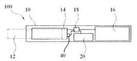
도 1에서, 전기 가열식 흡연 장치(100)의 구현예의 구성 요소들이 단순화된 방식으로 도시된다. 특히, 상기 전기 가열식 흡연 장치(100)의 요소들은 도 1에서 실제 축적대로 도시되지 않는다. 본 구현예의 이해와 무관한 요소들은 도 1을 단순화하기 위해 생략되었다. In Fig. 1, the components of the embodiment of the electric
전기 가열식 흡연 장치(100)는 예를 들어 궐련과 같은 흡연 물품 내에 에어로졸 형성 기재(12)를 수용하는 하우징(10)을 포함하고 있다. 하우징(10) 내에는 히터(14) 및 전기 에너지 공급부(16), 예를 들어 재충전 가능한 리튬 이온 배터리가 있다. 마이크로컨트롤러(18)는 가열 요소(14), 전기 에너지 공급부(16), 및 사용자 인터페이스(20), 예를 들어 버튼이나 디스플레이 또는 버튼과 디스플레이 모두에 연결된다. 마이크로컨트롤러(18)는 히터(14)의 온도를 조절하기 위해 히터에 공급되는 전력을 제어하기 위한 내장 소프트웨어를 갖는다. 에어로졸 형성 기재(12)는 하우징(10)의 공동으로 밀어 넣어져 히터(14)와 열적으로 근접하게 된다. 에어로졸 형성 기재(12)는 상이한 온도에서 다양한 휘발성 화합물을 방출한다. 전기 가열식 흡연 장치(100)의 최대 작동 온도가 휘발성 화합물의 일부가 방출되는 온도 미만이 되도록 제어함으로써, 이러한 연기 성분들의 방출 또는 형성이 회피될 수 있다. 일반적으로 에어로졸 형성 기재는 250℃ 내지 450℃의 온도로 가열된다. The electric
후술하는 바와 같이, 이미지 감지 모듈(40) 또한 마이크로컨트롤러에 연결된다. 후술하는 바와 같이, 마이크로컨트롤러(18)는 흡연 물품이 장치에 삽입된 후, 이미지 감지 모듈로부터의 데이터에 따라 가열체로 공급되는 전력을 제어한다. As will be described later, the
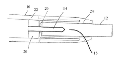
도 2는 감지 모듈이 없는, 도 1에 도시된 유형의 장치의 전방 단부의 개략적인 단면도이다. 흡연 물품(12)은 장치의 공동(15)에 수용된다. 히터(14)는 흡연 물품이 공동(15)에 수용될 때 에어로졸 형성 기재 내에 위치된 세라믹 블레이드(blade)이다. 하우징(10)은 고정부(22) 및 고정부에 대해 슬라이딩될 수 있는 전방부(24)를 갖는다. 히터는 하우징(22)의 고정부에 고정된 지지부(20)에 고정된다. 전방부(24)는 흡연 물품이 그 안에 수용되는 슬라이딩 수용부를 형성한다. 전방부는 흡연 물품과 히터 지지부(20) 사이에 후면(26)을 포함한다. 전방부를 공정부로부터 공동의 개방 단부를 향해 슬라이딩시킴으로써, 흡연 물품은 후면(26)에 의해 히터(14)로부터 분리되어, 장치로부터 쉽게 제거될 수 있다. Figure 2 is a schematic cross-sectional view of the front end of the device of the type shown in Figure 1 without the sensing module. The
도 1 및 도 2에 도시된 장치는 일반적으로 원통형 및 세장형이므로, 끝에 불이 붙는 궐련과 동일한 방식으로 한 손에 쉽게 유지될 수 있다. 장치는 흡연 물품에 비해 약간 큰 것이 바람직하다. 그 때문에, 흡연 물품 상의 마킹을 인식하기 위한 감지 시스템을 위한 공간이 장치의 전방 단부에 매우 한정되어 있다. 도 2에서는, 흡연 물품 상의 상이한 마킹을 구별하기 위해 충분한 광해상도를 제공하게 될 촬상 시스템용 공간이 거의 없다는 것을 구체적으로 알 수 있다. The device shown in Figures 1 and 2 is generally cylindrical and elongated so that it can be easily held in one hand in the same manner as a cigarette with a fire at the end. The device is preferably slightly larger than the smoking article. Therefore, the space for the sensing system for recognizing markings on the smoking article is very limited at the front end of the apparatus. It can be seen in detail in Figure 2 that there is little space for an imaging system that will provide sufficient optical resolution to distinguish different markings on the smoking article.
도 3은 본 발명에 따른 감지 시스템의 개략도이다. 도 3은 원형의 원통형 흡연 물품(12)을 보여주고 있다. 감지 시스템(40)은 흡연 물품의 만곡된 외부 표면에 인접하여 위치하고 있다. 감지 시스템은 인쇄 회로 기판(48) 상에 탑재된 패키지된 LED(42)를 포함하고 있다. 감지 시스템은 또한 LED(42)에 인접하여 인쇄 회로 기판 상에 탑재된 이미지 검출기(44)를 포함하고 있다. 복수의 마이크로렌즈(46)가 이미지 센서 상에 탑재되어 있다. 3 is a schematic diagram of a sensing system according to the present invention. Figure 3 shows a circular
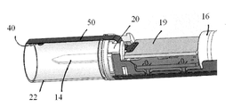
도 4a 및 도 4b는 감지 시스템이 흡연 장치 내에 어떻게 위치되는지를 보여주고 있다. 도 4a는 전방 하우징이 제거된, 장치의 전방 단부의 사시도이다. LED(42) 및 마이크로렌즈(46)가 공동(15) 내로 대면하고 있는 상태에서, 감지 시스템(40)이 하우징(22)의 고정된 부분에 탑재되어 있음을 볼 수 있다. Figures 4a and 4b show how the sensing system is located in a smoking device. 4A is a perspective view of the front end of the device with the front housing removed. It can be seen that the
도 4b는 고정된 하우징(22)이 투명하게 보이고 장치의 주 하우징 및 전방 하우징은 제거된, 장치의 전방 단부의 측면도이다. 감지 시스템(40)은 커넥터(50)에 의해 마이크로컨트롤러(18)를 포함한 제어 회로(19)에 연결되어 있다. 히터(14), 히터 지지부(20) 및 배터리(16)가 또한 보일 수 있다. 감지 시스템(40)은 고정된 하우징(22)의 애퍼쳐를 통해 커넥터(50)에 연결되어 있다. 도 2에 도시된 바와 같이, 명확성을 위해 도 4a 및 도 4b에 도시되지 않았지만, 고정된 하우징 위를 슬라이딩하는, 전방 하우징은 광이 감지 시스템으로 및 그로부터 흡연 물품으로부터 및 그로 통과하도록 그 속에 형성된 애퍼쳐를 가지고 있다. 4B is a side view of the front end of the apparatus with the fixed
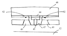
도 5a 및 도 5b는 감지 시스템(40)의 일 실시예를 보다 상세하게 도시하고 있다. 도 5a는 흡연 물품(12)의 곡면을 보여주는 공동을 가로지르는 단면도이다. 도 5b는 공동의 축방향을 따라, 도 5a에 수직인 단면도이다. 5A and 5B show one embodiment of the
도 5a 및 도 5b에 도시된 구현예에서, 이미지 검출기(44)는 0.3mm x 1.2mm의 크기를 갖는다. 이미지 검출기(44)를 덮기 위해 1차원 어레이로 배열된, 4개의 마이크로렌즈(45)가 있다. 마이크로렌즈 어레이는 공동의 축방향에 수직인 방향으로 연장되어 있다. 마이크로렌즈 어레이는 인쇄 회로 기판 (PCB)(48)에 고정된 지지 구조체(47)에 유지된다. 지지 구조체는 사출 성형된 플라스틱 재료로 형성된다. 지지 구조체에는 투명 광 가이드(49)가 제공되어 PCB에 고정된, LED(42)에 의해 방출된 광을 안내한다. 사용되는 LED 수는 전력 소모와 이미지 검출 속도 사이의 균형이다. 광이 많을수록 이미지 캡처는 빨라지게 하지만 전력 소모는 더 높아지게 된다. 2개의 LED를 사용하면 적절한 조도가 제공된다. 지지 구조체(47)는 불투명하고, 먼저 흡연 물품(12)으로부터 반사되지 않고 LED(42)로부터의 광이 검출기(44) 또는 렌즈 어레이(45)에 직접 도달하는 것을 방지한다. In the embodiment shown in Figs. 5A and 5B, the
감지 시스템은 그것의 수명 동안 큰 온도 변화를 겪기 때문에 열 안정성이 중요하다. 유리 재료는 대량의 광학 재료에 사용될 수 있다. 플라스틱 재료의 얇은 층은 원하는 광학 성능을 제공하기 위해 벌크 유리 상에 복제될 수 있다. 지지 구조체는 높은 열 안정성을 갖는 재료로 형성될 수 있다. Thermal stability is important because the sensing system undergoes a large temperature change during its lifetime. Glass materials can be used in large quantities of optical materials. A thin layer of plastic material can be replicated on the bulk glass to provide the desired optical performance. The support structure may be formed of a material having high thermal stability.
흡연 물품 상의 표시는 외측 종이 래퍼 상에 인쇄된다. 래퍼 종이는 흰색이다. 표시는 종이 위의 단순한 검은색 마킹일 수 있지만, 바람직한 구현예에서, 표시는 상이한 레벨의 회색들을 포함한다. 상이한 레벨의 회색은 잉크의 용량을 달리하거나, 감지 모듈이 분해할 수 있는 최소 형상 크기보다 작은 점들을 인쇄함으로써 생성될 수 있다. 표시는 1차원 바코드일 수 있으며, 바코드의 각 라인은 임의의 방향으로 공동 내에 놓여질 수 있도록 흡연 물품의 둘레 주위로 연장된다. 대안적으로, 2차원 바코드가 사용될 수 있고, 장치의 마이크로컨트롤러는 바코드의 시작 위치와 끝 위치를 판단할 수 있는 소프트웨어를 포함할 수 있다. The mark on the smoking article is printed on the outer paper wrapper. The wrapper paper is white. The indicia may be a simple black marking on paper, but in a preferred embodiment the indicia comprises different levels of gray. Different levels of gray can be created by varying the capacity of the ink, or by printing points smaller than the minimum feature size that the sensing module can resolve. The indicia can be a one-dimensional bar code, and each line of the bar code extends around the periphery of the smoking article so that it can be placed in the cavity in any direction. Alternatively, a two-dimensional barcode may be used, and the microcontroller of the device may include software that can determine the start and end positions of the barcode.
표시를 만드는데 사용된 잉크는 감지 모듈의 LED와 맞는 것이어야 한다. 따라서, LED가 적외선(IR) 광을 방출하는 경우, 잉크는 IR 광을 흡수해야 한다. 동일하게, 렌즈는 LED로부터의 광의 파장과 일치해야 한다. The ink used to make the marking must match the LEDs on the sensing module. Thus, when an LED emits infrared (IR) light, the ink must absorb IR light. Equally, the lens must match the wavelength of the light from the LED.
감지 시스템은, 도 1에 도시된 바와 같이 장치의 마이크로컨트롤러(18)에 연결된다. 마이크로컨트롤러는 하나 이상의 유형의 허용 가능한 흡연 용품에 관해 저장된 이미지 데이터와 이미지 검출기로부터의 이미지 데이터를 상관시키기 위한 소프트웨어를 포함한다. 사용자가 장치를 활성화시킨 후, 마이크로컨트롤러는 이미지 감지 모듈을 활성화시키고, 이미지 감지 모듈은 공동 내 흡연 물품의 이미지를 캡쳐한다. 캡쳐된 이미지는 이미지 데이터로서 마이크로컨트롤러로 전송된다. 마이크로컨트롤러(18)는 상기 이미지 데이터를 하나 이상의 유형의 허용 가능한 흡연 용품에 관해 저장된 이미지 데이터와 상관시킨다. 캡쳐된 이미지 데이터가 저장된 이미지 데이터와 충분히 상관되지 않는 경우, 마이크로컨트롤러는 히터로의 전력 공급을 중지시킨다. 캡쳐된 이미지 데이터가 저장된 이미지 데이터와 충분히 상관되는 경우, 마이크로컨트롤러는 히터로 전력이 공급되도록 한다. 마이크로컨트롤러는 캡처된 이미지 데이터가 가장 강하게 상관되는 저장된 이미지 데이터에 따라 히터가 특정 온도 프로파일 또는 전력 프로파일을 따르도록 히터로의 전력을 제어할 수 있다. The sensing system is connected to the
마이크로렌즈 어레이는 검출기에 반전된 이미지들의 모자이크를 제공한다. 마이크로컨트롤러(18)는 저장된 이미지 데이터와 상관시키기 위한 단일 이미지를 생성하기 위해 이미지들의 모자이크에 이미지 프로세싱을 수행하도록 구성될 수 있다. 대안적으로, 이미지들의 모자이크는 저장된 이미지 데이터와 직접 비교될 수 있다. The microlens array provides a mosaic of inverted images on the detector. The
전술한 예시적인 구현예들은 예시일 뿐이며 한정적인 것이 아님이 분명해야 한다. 위에서 논의된 예시적인 구현예를 고려하면, 상기 예시적인 구현예와 일치하는 다른 구현예는 이제 당업자에게 명백해질 것이다. It is to be understood that the above-described exemplary implementations are illustrative and not restrictive. Considering the exemplary implementation discussed above, other implementations consistent with the above exemplary implementation will now be apparent to those skilled in the art.
10: 하우징
12: 에어로졸 형성 기재
14: 히터
15: 공동
16: 전기 에너지 공급부
18: 마이크로컨트롤러
20: 사용자 인터페이스
22: 고정부
24: 전방부
26: 후면
40: 이미지 감지 모듈
42: LED
44: 이미지 검출기
45: 마이크로렌즈, 렌즈 어레이
46: 마이크로렌즈
47: 고정된 지지 구조체
48: 인쇄 회로 기판
49: 투명 광 가이드
50: 커넥터
100: 전기 가열식 흡연 장치10: Housing
12: Aerosol forming substrate
14: Heater
15: Co
16: Electric energy supplier
18: Microcontroller
20: User interface
22:
24:
26: Rear
40: Image sensing module
42: LED
44: image detector
45: Micro lens, lens array
46: Micro lens
47: Fixed support structure
48: printed circuit board
49: Transparent light guide
50: Connector
100: Electric heating smoking device
Claims (15)
상기 흡연 물품을 적어도 부분적으로 수용하기 위한 공동을 정의하는 하우징; 및
상기 흡연 물품 상의 표시를 검출하기 위한 감지 시스템을 포함하되, 상기 감지 시스템은 상기 공동의 주변에 위치되고, 광원, 이미지 검출기 및 상기 이미지 검출기 상에 위치한 복수의 마이크로렌즈를 포함하는, 전동식 흡연 장치. An electric smoking device configured to receive a smoking article,
A housing defining a cavity for at least partially receiving the smoking article; And
Wherein the sensing system comprises a light source, an image detector, and a plurality of microlenses positioned on the image detector, the sensing system being located at a periphery of the cavity and detecting an indication on the smoking article.
Applications Claiming Priority (3)
| Application Number | Priority Date | Filing Date | Title |
|---|---|---|---|
| EP15181085.0 | 2015-08-14 | ||
| EP15181085 | 2015-08-14 | ||
| PCT/EP2016/067888 WO2017029089A1 (en) | 2015-08-14 | 2016-07-27 | An electrically operated smoking device including a compact system for identifying smoking articles in the device |
Publications (1)
| Publication Number | Publication Date |
|---|---|
| KR20180033141A true KR20180033141A (en) | 2018-04-02 |
Family
ID=53836001
Family Applications (1)
| Application Number | Title | Priority Date | Filing Date |
|---|---|---|---|
| KR1020177037926A KR20180033141A (en) | 2015-08-14 | 2016-07-27 | An electric smoking device comprising a compact system for identification of smoking articles in a device |
Country Status (11)
| Country | Link |
|---|---|
| US (2) | US11166494B2 (en) |
| EP (1) | EP3334296B2 (en) |
| JP (2) | JP6895947B2 (en) |
| KR (1) | KR20180033141A (en) |
| CN (4) | CN107920588A (en) |
| CA (1) | CA2986335A1 (en) |
| IL (1) | IL255518B1 (en) |
| MX (1) | MX2018001614A (en) |
| PL (1) | PL3334296T5 (en) |
| RU (1) | RU2710657C2 (en) |
| WO (1) | WO2017029089A1 (en) |
Cited By (10)
| Publication number | Priority date | Publication date | Assignee | Title |
|---|---|---|---|---|
| WO2019208974A1 (en) * | 2018-04-25 | 2019-10-31 | 주식회사 케이티앤지 | Aerosol generation device |
| KR102055749B1 (en) * | 2018-06-15 | 2019-12-13 | 주식회사 이엠텍 | Drip tip for electric heating type aerosol generator |
| KR20190143146A (en) * | 2018-06-20 | 2019-12-30 | 주식회사 이엠텍 | A fine particle generator |
| WO2020017821A1 (en) * | 2018-07-18 | 2020-01-23 | 주식회사 케이티앤지 | Aerosol generating device and heater assembly for aerosol generating device |
| WO2020105896A1 (en) * | 2018-11-23 | 2020-05-28 | 주식회사 케이티앤지 | Aerosol generating device and method for operating same |
| WO2020149505A1 (en) * | 2019-01-16 | 2020-07-23 | 주식회사 케이티앤지 | Method for controlling aerosol generating device with plurality of geomagnetic sensors, and aerosol generating device |
| KR20210043530A (en) * | 2018-11-23 | 2021-04-21 | 주식회사 케이티앤지 | Aerosol generating apparatus and method for operating the same |
| KR20210099626A (en) * | 2019-01-15 | 2021-08-12 | 필립모리스 프로덕츠 에스.에이. | Aerosol-generating device with removable top cover |
| KR20220012624A (en) | 2020-07-23 | 2022-02-04 | 주식회사 코아리버 | Electronic smoking tool |
| WO2022270797A1 (en) * | 2021-06-23 | 2022-12-29 | Kt&G Corporation | Aerosol generating device and operation method thereof |
Families Citing this family (44)
| Publication number | Priority date | Publication date | Assignee | Title |
|---|---|---|---|---|
| WO2017029089A1 (en) * | 2015-08-14 | 2017-02-23 | Philip Morris Products S.A. | An electrically operated smoking device including a compact system for identifying smoking articles in the device |
| UA125699C2 (en) | 2016-12-16 | 2022-05-18 | Кт & Г Корпорейшон | Aerosol generation method and apparatus |
| US20200154772A1 (en) | 2017-04-11 | 2020-05-21 | Kt&G Corporation | Aerosol generation system of preheating heater |
| US11771138B2 (en) | 2017-04-11 | 2023-10-03 | Kt&G Corporation | Aerosol generating device and method for providing smoking restriction function in aerosol generating device |
| US11432593B2 (en) | 2017-04-11 | 2022-09-06 | Kt&G Corporation | Device for cleaning smoking member, and smoking member system |
| US11622582B2 (en) | 2017-04-11 | 2023-04-11 | Kt&G Corporation | Aerosol generating device and method for providing adaptive feedback through puff recognition |
| CN115777993A (en) | 2017-04-11 | 2023-03-14 | 韩国烟草人参公社 | Aerosol-generating system |
| KR102281875B1 (en) * | 2017-04-11 | 2021-07-27 | 주식회사 케이티앤지 | Method and apparatus for controlling electronic cigarettes |
| KR20180114825A (en) | 2017-04-11 | 2018-10-19 | 주식회사 케이티앤지 | Method and apparatus for controlling electronic cigarettes |
| US11252999B2 (en) | 2017-04-11 | 2022-02-22 | Kt&G Corporation | Aerosol generating device |
| KR20180124739A (en) * | 2017-05-11 | 2018-11-21 | 주식회사 케이티앤지 | An aerosol generating device for controlling the temperature of a heater according to the type of cigarette and method thereof |
| CA3063034C (en) | 2017-05-11 | 2021-04-13 | Kt&G Corporation | Vaporizer and aerosol generation device including same |
| KR102035313B1 (en) | 2017-05-26 | 2019-10-22 | 주식회사 케이티앤지 | Heater assembly and aerosol generating apparatus having the same |
| KR102231228B1 (en) * | 2017-05-26 | 2021-03-24 | 주식회사 케이티앤지 | Apparatus and method for generating aerosol having cigarette insertion detection function |
| WO2019031877A2 (en) | 2017-08-09 | 2019-02-14 | 주식회사 케이티앤지 | Aerosol generation device and control method for aerosol generation device |
| KR20190049391A (en) | 2017-10-30 | 2019-05-09 | 주식회사 케이티앤지 | Aerosol generating apparatus having heater |
| WO2019031871A1 (en) | 2017-08-09 | 2019-02-14 | 주식회사 케이티앤지 | Electronic cigarette control method and device |
| EP3997993A1 (en) | 2017-09-06 | 2022-05-18 | KT&G Corporation | Aerosol generation device |
| KR102141648B1 (en) * | 2017-10-30 | 2020-08-05 | 주식회사 케이티앤지 | An apparatus for generating aerosols and a method for controlling the apparatus |
| KR102012851B1 (en) * | 2017-10-30 | 2019-08-21 | 주식회사 케이티앤지 | Aerosol generating device and method for controlling the same |
| EP3704972A4 (en) | 2017-10-30 | 2021-09-15 | KT&G Corporation | Aerosol generation device and heater for aerosol generation device |
| KR102138245B1 (en) | 2017-10-30 | 2020-07-28 | 주식회사 케이티앤지 | Aerosol generating apparatus |
| JP6884264B2 (en) | 2017-10-30 | 2021-06-09 | ケイティー アンド ジー コーポレイション | Aerosol generator |
| US11528936B2 (en) | 2017-10-30 | 2022-12-20 | Kt&G Corporation | Aerosol generating device |
| KR102180421B1 (en) | 2017-10-30 | 2020-11-18 | 주식회사 케이티앤지 | Apparatus for generating aerosols |
| KR102057216B1 (en) | 2017-10-30 | 2019-12-18 | 주식회사 케이티앤지 | An apparatus for generating aerosols and A heater assembly therein |
| KR102057215B1 (en) | 2017-10-30 | 2019-12-18 | 주식회사 케이티앤지 | Method and apparatus for generating aerosols |
| RU2738549C1 (en) | 2017-10-30 | 2020-12-14 | Кейтиэндджи Корпорейшн | Device for aerosol generation and method of such device control |
| KR102138246B1 (en) | 2017-10-30 | 2020-07-28 | 주식회사 케이티앤지 | Vaporizer and aerosol generating apparatus comprising the same |
| DE102017222528B3 (en) | 2017-12-12 | 2019-01-24 | Heraeus Sensor Technology Gmbh | Heating unit for a system for providing an inhalable aerosol |
| JP7202381B2 (en) * | 2017-12-29 | 2023-01-11 | ジェイティー インターナショナル エス.エイ. | Inhaler with optical recognition and consumables therefor |
| TW201931945A (en) | 2017-12-29 | 2019-08-01 | 瑞士商傑太日煙國際股份有限公司 | Heating assembly for a vapour generating device |
| GB201805169D0 (en) * | 2018-03-29 | 2018-05-16 | Nicoventures Holdings Ltd | A control device for an electronic aerosol provision system |
| KR102323786B1 (en) * | 2018-06-18 | 2021-11-09 | 주식회사 이엠텍 | Fine particle generator |
| TW202104895A (en) * | 2019-01-11 | 2021-02-01 | 日商日本煙草產業股份有限公司 | In vitro evaluation method of chronic obstructive pulmonary disease risks caused by smoking or inhaling |
| KR102413551B1 (en) * | 2019-10-21 | 2022-06-27 | 주식회사 케이티앤지 | Aerosol generating device including holder generating aerosol and cradle for holder, and cradle for holder generating aerosol |
| WO2021081757A1 (en) * | 2019-10-29 | 2021-05-06 | 昆山联滔电子有限公司 | Electronic cigarette authenticity recognition system and method, and vaping set, electronic cigarette and storage medium |
| JP2023505934A (en) * | 2019-12-20 | 2023-02-14 | ジェイティー インターナショナル エス.エイ. | Optically encoded aerosol-generating smoking article and system including smoking article |
| EP4076068A1 (en) * | 2019-12-20 | 2022-10-26 | JT International SA | Aerosol generation device with optical code detector |
| KR102423898B1 (en) * | 2020-04-16 | 2022-07-21 | 주식회사 케이티앤지 | Aerosol generating device |
| JP2024506698A (en) * | 2021-02-23 | 2024-02-14 | ジェイティー インターナショナル エスエイ | Electric smoking device including an optical detection system for identifying indicia on smoking articles |
| WO2023057631A1 (en) * | 2021-10-08 | 2023-04-13 | Jt International S.A. | Aerosol generating device comprising a led |
| KR20230072660A (en) * | 2021-11-18 | 2023-05-25 | 주식회사 케이티앤지 | Method and apparatus for generating aerosol |
| WO2024049051A1 (en) * | 2022-08-30 | 2024-03-07 | Kt&G Corporation | Aerosol generating device and method of manufacturing outer cover for aerosol generating device |
Family Cites Families (39)
| Publication number | Priority date | Publication date | Assignee | Title |
|---|---|---|---|---|
| US236708A (en) * | 1881-01-18 | Fourth to adam good | ||
| US5060671A (en) | 1989-12-01 | 1991-10-29 | Philip Morris Incorporated | Flavor generating article |
| US5388594A (en) | 1991-03-11 | 1995-02-14 | Philip Morris Incorporated | Electrical smoking system for delivering flavors and method for making same |
| US5505214A (en) | 1991-03-11 | 1996-04-09 | Philip Morris Incorporated | Electrical smoking article and method for making same |
| JPH04330850A (en) * | 1991-05-02 | 1992-11-18 | Kanegafuchi Chem Ind Co Ltd | Contact type image sensor unit |
| US6226120B1 (en) * | 1994-11-30 | 2001-05-01 | Board Of Supervisors Of Louisiana State University And Agricultural And Mechanical College | Three-dimensional microstructures, and methods for making three-dimensional microstructures |
| JP2001157664A (en) * | 1999-12-03 | 2001-06-12 | Asahi Optical Co Ltd | Image pickup element for electronic endoscope and electronic endoscope |
| US6540392B1 (en) * | 2000-03-31 | 2003-04-01 | Sensar, Inc. | Micro-illuminator for use with image recognition system |
| WO2003059424A1 (en) * | 2002-01-15 | 2003-07-24 | Aerogen, Inc. | Methods and systems for operating an aerosol generator |
| CN2586215Y (en) * | 2002-12-11 | 2003-11-12 | 系统电子工业股份有限公司 | Optical inputting induction structure |
| US7208719B2 (en) * | 2003-05-14 | 2007-04-24 | Hewlett-Packard Development Company, L.P. | Compact integrated optical imaging assembly |
| CN2681352Y (en) * | 2003-12-05 | 2005-02-23 | 鸿富锦精密工业(深圳)有限公司 | Image sensor |
| US7309011B2 (en) | 2004-10-29 | 2007-12-18 | Symbol Technologies, Inc. | Method of authenticating products using hardware compatibility flag |
| GB0426162D0 (en) | 2004-11-29 | 2004-12-29 | Molins Plc | Ignition system |
| US20060202104A1 (en) | 2005-03-14 | 2006-09-14 | Microalign Technologies, Inc. | Contact-type monolithic image sensor |
| KR100784090B1 (en) * | 2005-10-25 | 2007-12-10 | 엘지이노텍 주식회사 | light emitting module and backlight unit having the same |
| KR100832073B1 (en) * | 2006-11-15 | 2008-05-27 | 삼성전기주식회사 | Optical sensor module |
| US8718319B2 (en) * | 2007-06-15 | 2014-05-06 | Cognex Corporation | Method and system for optoelectronic detection and location of objects |
| CN101751154A (en) * | 2008-12-16 | 2010-06-23 | 义隆电子股份有限公司 | COB module of optical mouse and optical mouse |
| EP2201850A1 (en) * | 2008-12-24 | 2010-06-30 | Philip Morris Products S.A. | An article including identification information for use in an electrically heated smoking system |
| US20160059429A1 (en) * | 2009-08-22 | 2016-03-03 | Laura Jane Mayes | Double headed knife |
| CN201497957U (en) * | 2009-09-03 | 2010-06-02 | 曹国莉 | Integrated optical mouse module |
| KR101128931B1 (en) * | 2010-08-11 | 2012-03-27 | 삼성전기주식회사 | Camera module |
| DE102010063523A1 (en) * | 2010-12-20 | 2012-06-21 | Hauni Maschinenbau Ag | Perforation of cigarettes |
| EP2468118A1 (en) | 2010-12-24 | 2012-06-27 | Philip Morris Products S.A. | An aerosol generating system with means for disabling a consumable |
| ES2536954T3 (en) * | 2011-10-21 | 2015-06-01 | Philip Morris Products S.A. | Smoking item that has a mouth end cavity with markings |
| MY168320A (en) | 2011-11-21 | 2018-10-30 | Philip Morris Products Sa | Extractor for an aerosol-generating device |
| CN103974640B (en) | 2011-12-30 | 2017-03-08 | 菲利普莫里斯生产公司 | There is the aerosol generating device of improved Temperature Distribution |
| CN102681046B (en) * | 2012-05-17 | 2014-04-16 | 中北大学 | Method for preparing large-area NOA73 curved-surface micro lens array |
| MY184440A (en) * | 2013-03-15 | 2021-04-01 | Altria Client Services Llc | Accesory for electronic cigarette |
| CN203986093U (en) | 2013-09-13 | 2014-12-10 | 惠州市吉瑞科技有限公司 | A kind of battery component of electronic cigarette, atomizing component and electronic cigarette |
| CN203646504U (en) | 2013-11-29 | 2014-06-18 | 刘秋明 | Battery pack of electronic cigarette, atomization assembly of electronic cigarette, and electronic cigarette |
| EP3076812B1 (en) | 2013-12-03 | 2018-05-09 | Philip Morris Products S.a.s. | Aerosol-generating article and electrically operated system incorporating a taggant |
| CN103704886B (en) | 2013-12-31 | 2016-03-23 | 广东中烟工业有限责任公司 | Tobacco heating device with smoking prompt function |
| CN103777256A (en) * | 2014-01-22 | 2014-05-07 | 广州中国科学院先进技术研究所 | Manufacturing method and application for flexible curved micro-lens array |
| NO3110696T3 (en) * | 2014-02-06 | 2018-05-12 | ||
| EP3142502B1 (en) * | 2014-05-12 | 2019-12-04 | Kanben Services Inc. | Electrically-powered hookah |
| US10236708B2 (en) * | 2014-07-24 | 2019-03-19 | Nicoventures Holdings Limited | Re-charging pack for an e-cigarette |
| WO2017029089A1 (en) * | 2015-08-14 | 2017-02-23 | Philip Morris Products S.A. | An electrically operated smoking device including a compact system for identifying smoking articles in the device |
-
2016
- 2016-07-27 WO PCT/EP2016/067888 patent/WO2017029089A1/en active Application Filing
- 2016-07-27 IL IL255518A patent/IL255518B1/en unknown
- 2016-07-27 JP JP2018506520A patent/JP6895947B2/en active Active
- 2016-07-27 US US15/735,688 patent/US11166494B2/en active Active
- 2016-07-27 PL PL16744393.6T patent/PL3334296T5/en unknown
- 2016-07-27 KR KR1020177037926A patent/KR20180033141A/en not_active Application Discontinuation
- 2016-07-27 CN CN201680040686.4A patent/CN107920588A/en active Pending
- 2016-07-27 RU RU2017145214A patent/RU2710657C2/en active
- 2016-07-27 CN CN202311390836.2A patent/CN117256966A/en active Pending
- 2016-07-27 CN CN202311390835.8A patent/CN117256965A/en active Pending
- 2016-07-27 MX MX2018001614A patent/MX2018001614A/en unknown
- 2016-07-27 CA CA2986335A patent/CA2986335A1/en not_active Abandoned
- 2016-07-27 CN CN202311390832.4A patent/CN117256964A/en active Pending
- 2016-07-27 EP EP16744393.6A patent/EP3334296B2/en active Active
-
2021
- 2021-06-08 JP JP2021095585A patent/JP7262514B2/en active Active
- 2021-10-08 US US17/497,411 patent/US20220022548A1/en active Pending
Cited By (15)
| Publication number | Priority date | Publication date | Assignee | Title |
|---|---|---|---|---|
| WO2019208974A1 (en) * | 2018-04-25 | 2019-10-31 | 주식회사 케이티앤지 | Aerosol generation device |
| KR102055749B1 (en) * | 2018-06-15 | 2019-12-13 | 주식회사 이엠텍 | Drip tip for electric heating type aerosol generator |
| KR20190143146A (en) * | 2018-06-20 | 2019-12-30 | 주식회사 이엠텍 | A fine particle generator |
| WO2020017821A1 (en) * | 2018-07-18 | 2020-01-23 | 주식회사 케이티앤지 | Aerosol generating device and heater assembly for aerosol generating device |
| KR20200009376A (en) * | 2018-07-18 | 2020-01-30 | 주식회사 케이티앤지 | Aerosol generating apparatus and heater assembly thereof |
| KR20200061233A (en) * | 2018-11-23 | 2020-06-02 | 주식회사 케이티앤지 | Aerosol generating apparatus and method for operating the same |
| WO2020105896A1 (en) * | 2018-11-23 | 2020-05-28 | 주식회사 케이티앤지 | Aerosol generating device and method for operating same |
| KR20210043530A (en) * | 2018-11-23 | 2021-04-21 | 주식회사 케이티앤지 | Aerosol generating apparatus and method for operating the same |
| US11882875B2 (en) | 2018-11-23 | 2024-01-30 | Kt&G Corporation | Aerosol generating apparatus and operation method of the same |
| KR20210099626A (en) * | 2019-01-15 | 2021-08-12 | 필립모리스 프로덕츠 에스.에이. | Aerosol-generating device with removable top cover |
| WO2020149505A1 (en) * | 2019-01-16 | 2020-07-23 | 주식회사 케이티앤지 | Method for controlling aerosol generating device with plurality of geomagnetic sensors, and aerosol generating device |
| KR20200089152A (en) * | 2019-01-16 | 2020-07-24 | 주식회사 케이티앤지 | Method for controlling aerosol generating apparatus using multiple geomagnetic sensors and apparatus thereof |
| US11882882B2 (en) | 2019-01-16 | 2024-01-30 | Kt&G Corporation | Method of controlling aerosol generating device with a plurality of geomagnetic sensors and aerosol generating device controlled thereby |
| KR20220012624A (en) | 2020-07-23 | 2022-02-04 | 주식회사 코아리버 | Electronic smoking tool |
| WO2022270797A1 (en) * | 2021-06-23 | 2022-12-29 | Kt&G Corporation | Aerosol generating device and operation method thereof |
Also Published As
| Publication number | Publication date |
|---|---|
| JP7262514B2 (en) | 2023-04-21 |
| IL255518B1 (en) | 2024-02-01 |
| JP6895947B2 (en) | 2021-06-30 |
| WO2017029089A1 (en) | 2017-02-23 |
| RU2710657C2 (en) | 2019-12-30 |
| US20190261682A1 (en) | 2019-08-29 |
| IL255518A (en) | 2018-01-31 |
| JP2021168654A (en) | 2021-10-28 |
| RU2017145214A (en) | 2019-09-16 |
| JP2018527916A (en) | 2018-09-27 |
| US11166494B2 (en) | 2021-11-09 |
| CN117256964A (en) | 2023-12-22 |
| US20220022548A1 (en) | 2022-01-27 |
| EP3334296A1 (en) | 2018-06-20 |
| PL3334296T5 (en) | 2023-06-26 |
| MX2018001614A (en) | 2018-05-22 |
| CN117256965A (en) | 2023-12-22 |
| PL3334296T3 (en) | 2021-01-11 |
| RU2017145214A3 (en) | 2019-10-29 |
| EP3334296B2 (en) | 2023-04-05 |
| CA2986335A1 (en) | 2017-02-23 |
| CN117256966A (en) | 2023-12-22 |
| EP3334296B1 (en) | 2020-07-22 |
| CN107920588A (en) | 2018-04-17 |
Similar Documents
| Publication | Publication Date | Title |
|---|---|---|
| JP7262514B2 (en) | Electrically operated smoking device including a compact system for identifying smoking articles within the device | |
| US20210307403A1 (en) | Electrically operated smoking device including a system for identifying smoking articles in the device | |
| KR102511212B1 (en) | Electrically operated aerosol-generating system having means for detecting tubular aerosol-generating articles | |
| JP6026556B2 (en) | Aerosol generator with improved temperature distribution | |
| JP6663417B2 (en) | Aerosol generation system with cartridge detection | |
| JP2021072836A (en) | Long heater assembly for aerosol generation system and heating assembly | |
| EP3911189A1 (en) | Aerosol-generating device with closable cavity | |
| EP3787428B1 (en) | Smoking substitute device having a flexible seal between battery and consumable | |
| WO2023041487A1 (en) | A smoking substitute device | |
| KR20170134376A (en) | A bag for an aerosol-forming substrate, a method of making the same, and an aerosol generating device for use with a bag |
Legal Events
| Date | Code | Title | Description |
|---|---|---|---|
| A201 | Request for examination | ||
| E902 | Notification of reason for refusal | ||
| E601 | Decision to refuse application |