KR20170142681A - Light guide panel for the direct type BLU - Google Patents
Light guide panel for the direct type BLU Download PDFInfo
- Publication number
- KR20170142681A KR20170142681A KR1020160076553A KR20160076553A KR20170142681A KR 20170142681 A KR20170142681 A KR 20170142681A KR 1020160076553 A KR1020160076553 A KR 1020160076553A KR 20160076553 A KR20160076553 A KR 20160076553A KR 20170142681 A KR20170142681 A KR 20170142681A
- Authority
- KR
- South Korea
- Prior art keywords
- light
- light guide
- guide plate
- direct
- backlight unit
- Prior art date
Links
Images


Classifications
-
- G—PHYSICS
- G02—OPTICS
- G02F—OPTICAL DEVICES OR ARRANGEMENTS FOR THE CONTROL OF LIGHT BY MODIFICATION OF THE OPTICAL PROPERTIES OF THE MEDIA OF THE ELEMENTS INVOLVED THEREIN; NON-LINEAR OPTICS; FREQUENCY-CHANGING OF LIGHT; OPTICAL LOGIC ELEMENTS; OPTICAL ANALOGUE/DIGITAL CONVERTERS
- G02F1/00—Devices or arrangements for the control of the intensity, colour, phase, polarisation or direction of light arriving from an independent light source, e.g. switching, gating or modulating; Non-linear optics
- G02F1/01—Devices or arrangements for the control of the intensity, colour, phase, polarisation or direction of light arriving from an independent light source, e.g. switching, gating or modulating; Non-linear optics for the control of the intensity, phase, polarisation or colour
- G02F1/13—Devices or arrangements for the control of the intensity, colour, phase, polarisation or direction of light arriving from an independent light source, e.g. switching, gating or modulating; Non-linear optics for the control of the intensity, phase, polarisation or colour based on liquid crystals, e.g. single liquid crystal display cells
- G02F1/133—Constructional arrangements; Operation of liquid crystal cells; Circuit arrangements
- G02F1/1333—Constructional arrangements; Manufacturing methods
- G02F1/1335—Structural association of cells with optical devices, e.g. polarisers or reflectors
- G02F1/133524—Light-guides, e.g. fibre-optic bundles, louvered or jalousie light-guides
-
- G—PHYSICS
- G02—OPTICS
- G02B—OPTICAL ELEMENTS, SYSTEMS OR APPARATUS
- G02B6/00—Light guides; Structural details of arrangements comprising light guides and other optical elements, e.g. couplings
- G02B6/0001—Light guides; Structural details of arrangements comprising light guides and other optical elements, e.g. couplings specially adapted for lighting devices or systems
- G02B6/0011—Light guides; Structural details of arrangements comprising light guides and other optical elements, e.g. couplings specially adapted for lighting devices or systems the light guides being planar or of plate-like form
- G02B6/0033—Means for improving the coupling-out of light from the light guide
- G02B6/0035—Means for improving the coupling-out of light from the light guide provided on the surface of the light guide or in the bulk of it
- G02B6/0045—Means for improving the coupling-out of light from the light guide provided on the surface of the light guide or in the bulk of it by shaping at least a portion of the light guide
- G02B6/0046—Tapered light guide, e.g. wedge-shaped light guide
-
- G—PHYSICS
- G02—OPTICS
- G02B—OPTICAL ELEMENTS, SYSTEMS OR APPARATUS
- G02B6/00—Light guides; Structural details of arrangements comprising light guides and other optical elements, e.g. couplings
- G02B6/0001—Light guides; Structural details of arrangements comprising light guides and other optical elements, e.g. couplings specially adapted for lighting devices or systems
- G02B6/0011—Light guides; Structural details of arrangements comprising light guides and other optical elements, e.g. couplings specially adapted for lighting devices or systems the light guides being planar or of plate-like form
- G02B6/0066—Light guides; Structural details of arrangements comprising light guides and other optical elements, e.g. couplings specially adapted for lighting devices or systems the light guides being planar or of plate-like form characterised by the light source being coupled to the light guide
- G02B6/0073—Light emitting diode [LED]
-
- G—PHYSICS
- G02—OPTICS
- G02B—OPTICAL ELEMENTS, SYSTEMS OR APPARATUS
- G02B6/00—Light guides; Structural details of arrangements comprising light guides and other optical elements, e.g. couplings
- G02B6/10—Light guides; Structural details of arrangements comprising light guides and other optical elements, e.g. couplings of the optical waveguide type
- G02B6/12—Light guides; Structural details of arrangements comprising light guides and other optical elements, e.g. couplings of the optical waveguide type of the integrated circuit kind
-
- G—PHYSICS
- G02—OPTICS
- G02F—OPTICAL DEVICES OR ARRANGEMENTS FOR THE CONTROL OF LIGHT BY MODIFICATION OF THE OPTICAL PROPERTIES OF THE MEDIA OF THE ELEMENTS INVOLVED THEREIN; NON-LINEAR OPTICS; FREQUENCY-CHANGING OF LIGHT; OPTICAL LOGIC ELEMENTS; OPTICAL ANALOGUE/DIGITAL CONVERTERS
- G02F1/00—Devices or arrangements for the control of the intensity, colour, phase, polarisation or direction of light arriving from an independent light source, e.g. switching, gating or modulating; Non-linear optics
- G02F1/01—Devices or arrangements for the control of the intensity, colour, phase, polarisation or direction of light arriving from an independent light source, e.g. switching, gating or modulating; Non-linear optics for the control of the intensity, phase, polarisation or colour
- G02F1/13—Devices or arrangements for the control of the intensity, colour, phase, polarisation or direction of light arriving from an independent light source, e.g. switching, gating or modulating; Non-linear optics for the control of the intensity, phase, polarisation or colour based on liquid crystals, e.g. single liquid crystal display cells
- G02F1/133—Constructional arrangements; Operation of liquid crystal cells; Circuit arrangements
- G02F1/1333—Constructional arrangements; Manufacturing methods
- G02F1/1335—Structural association of cells with optical devices, e.g. polarisers or reflectors
- G02F1/1336—Illuminating devices
- G02F1/133602—Direct backlight
- G02F1/133603—Direct backlight with LEDs
-
- G—PHYSICS
- G02—OPTICS
- G02B—OPTICAL ELEMENTS, SYSTEMS OR APPARATUS
- G02B6/00—Light guides; Structural details of arrangements comprising light guides and other optical elements, e.g. couplings
- G02B6/10—Light guides; Structural details of arrangements comprising light guides and other optical elements, e.g. couplings of the optical waveguide type
- G02B6/12—Light guides; Structural details of arrangements comprising light guides and other optical elements, e.g. couplings of the optical waveguide type of the integrated circuit kind
- G02B2006/12035—Materials
- G02B2006/12069—Organic material
- G02B2006/12071—PMMA
Abstract
Description
본 발명은 백라이트유닛에 관한 것이며, 더욱 상세히는 직하 방식 백라이트유닛용 도광판에 관한 것이다.The present invention relates to a backlight unit, and more particularly, to a light guide plate for a direct-type backlight unit.
백라이트유닛(BLU; Back Light Unit)은 액정패널(Liquid Crystal Panel), 드라이버(Driver) IC, 기판(예컨대, PCB) 등과 함께 액정표시장치(Liquid Crystal Display)를 구성하는 부분품으로, 자체 발광이 되지 않는 액정패널의 하부에 위치하여 균일한 평면 광을 조사시켜 액정표시장치(LCD)의 화상을 인식할 수 있도록 하는 광원장치이다.A backlight unit (BLU) is a component that constitutes a liquid crystal display together with a liquid crystal panel, a driver IC, a substrate (e.g., PCB) Which is positioned below the liquid crystal panel and irradiates uniform planar light to enable the image of the liquid crystal display (LCD) to be recognized.
상기한 백라이트유닛은 냉음극 형광램프(CCFL: Cold Cathode Fluorescent Lamp), 열음극 형광램프(HCFL: Hot Cathode Fluorescent Lamp), 외부전극 방전램프(EEFL: External Electrode Fluorescent Lamp) 등의 원통형 형광램프나 LED(Light-emitting diode) 및 전계발광(EL: Electro Luminescence) 소자 등을 광원으로 사용하며, 최근에는 친환경성, 에너지 절감, 수명 연장 및 내구성 등의 이유로 LED를 광원으로 사용하는 경우가 증가하고 있다.The backlight unit may include a cylindrical fluorescent lamp such as a cold cathode fluorescent lamp (CCFL), a hot cathode fluorescent lamp (HCFL), an external electrode discharge lamp (EEFL) Light-emitting diodes (LEDs) and electroluminescence (EL) devices are used as light sources. In recent years, LEDs are increasingly used as a light source for reasons of environment friendliness, energy saving, life span and durability.
특허문헌 1에 게시된 바와 같이, LED를 이용하는 백라이트유닛은 LED 광원의 설치 위치에 따라 크게 에지 방식(Edge type)과 직하 방식(Direct type)으로 구분된다.As disclosed in Patent Document 1, a backlight unit using an LED is roughly classified into an edge type and a direct type depending on the installation position of the LED light source.
상기한 에지 방식 백라이트유닛은 도광판(Light Guide Panel) 아랫면으로 빠져나오는 빛을 다시 반사시켜 도광판 내로 돌려보내는 반사시트(Reflector Sheet) 상에 LED로부터 방출되는 빛을 받아들이고 표면에 형성된 일정 면적과 모양을 가진 패턴을 통해 액정표시장치(LCD)의 화면 표시 영역에 걸쳐 빛을 균일하게 분포시켜 주는 도광판이 설치되고, 도광판 양측에는 다수개의 LED가 설치된 기판(예컨대, PCB)이 각각 구비되며, 도광판 상부에는 도광판 표면으로부터 일정한 방향으로 빠져나오는 빛을 산란시켜 도광판 표면 전반에 걸쳐 균일하게 확산시키는 확산시트(Diffuser Sheet)가 설치되고, 확산시트 상부에는 확산시트에서 나오는 빛을 굴절, 집광시켜 휘도를 높이는 프리즘시트(Prism Sheet)가 설치되고, 프리즘시트 상부에는 프리즘시트를 보호하고 빛을 확산시켜 프리즘 시트에 의해 좁아진 시야각을 넓혀 주는 보호시트(Protect Sheet)가 설치된다. 상기와 같이 설치되는 반사시트, 도광판, 기판(예컨대, PCB), 확산시트, 프리즘시트, 및 보호시트는 케이스 역할을 하는 몰드 프레임(Mold Frame)에 의해 고정된다.The edge-type backlight unit receives light emitted from the LED on a reflective sheet that reflects light coming out to a lower surface of a light guide panel back to the light guide plate, and has a predetermined area and shape A light guide plate for uniformly distributing light over a screen display region of a liquid crystal display (LCD) through a pattern, a substrate (e.g., PCB) having a plurality of LEDs installed on both sides of the light guide plate, A diffuser sheet for uniformly diffusing light that escapes from the surface in a predetermined direction so as to diffuse uniformly over the entire surface of the light guide plate is provided and a prism sheet for increasing the brightness by refracting and condensing light emitted from the diffuser sheet A prism sheet is installed, and a prism sheet is protected at the top of the prism sheet, The protection sheet (Sheet Protect) to widen the viewing angle narrowed by the seat algorithm is provided. The reflective sheet, the light guide plate, the substrate (e.g., PCB), the diffusion sheet, the prism sheet, and the protective sheet installed as described above are fixed by a mold frame serving as a case.
이와 달리, 상기한 직하 방식 백라이트유닛은 다수개의 LED로 구성된 다수개의 LED 어레이가 설치된 기판(예컨대, PCB) 상부에 반사시트가 설치되고, 반사시트 상부에 도광판, 확산시트, 프리즘시트, 및 보호시트가 순차적으로 설치된다. 상기와 같이 설치되는 기판(예컨대, PCB), 반사시트, 도광판, 확산시트, 프리즘시트, 및 보호시트는 케이스 역할을 하는 몰드 프레임(Mold Frame)에 의해 고정된다.Alternatively, the direct-type backlight unit may include a reflective sheet on a substrate (e.g., a PCB) having a plurality of LED arrays including a plurality of LEDs, a light guide plate, a diffusion sheet, a prism sheet, Are sequentially installed. The substrate (e.g., PCB), the reflective sheet, the light guide plate, the diffusion sheet, the prism sheet, and the protective sheet installed as described above are fixed by a mold frame serving as a case.
한편, 상기한 직하 방식 백라이트유닛은 LED 어레이가 상기 도광판 하부에 설치되어 액정표시장치(LCD)의 표시 영역의 광 조사영역별로 로컬 디밍(Local dimming)이 가능하기 때문에 화면의 해상도를 높이는 동시에 전력 소모 효율을 높일 수 있다는 장점이 있다.Meanwhile, since the direct-type backlight unit is provided under the light guide plate and local dimming can be performed for each light irradiation area of a display area of a liquid crystal display (LCD), the resolution of the screen can be increased, The advantage is that the efficiency can be increased.
하지만, 상기한 직하 방식 백라이트유닛은 액정표시장치(LCD)의 화면 표시 영역 중 광 조사영역의 직하 지점에 LED가 위치하기 때문에 해당 광 조사영역 내에서 LED가 위치하는 지점이 여타 영역에 비하여 밝게 나타나는 화이트-스팟(White-spot) 현상이 발생하게 된다.However, since the direct-type backlight unit has an LED positioned at a position directly under the light-irradiated area in the screen display area of the liquid crystal display (LCD), the point where the LED is positioned in the light- A white-spot phenomenon occurs.
따라서, 상기한 직하 방식 백라이트유닛은 상기한 화이트-스팟 현상을 억제하고 LED로부터 방출되는 빛이 충분히 균일하게 광 조사영역에 확산하게 하기 위해서 LED와 도광판 사이에 빛의 확산을 위한 에어갭(Air-gap)을 설치하고, 도광판의 두께를 늘려야 하는 등의 설계 제한이 있으며, 이로 인해 직하 방식 백라이트유닛의 두께를 슬림화하는 데에도 제한이 있다.Therefore, in order to suppress the white spot phenomenon and diffuse the light emitted from the LED sufficiently uniformly in the light irradiation area, the direct-type backlight unit is provided with an air gap for diffusing light between the LED and the light guide plate, gap, and the thickness of the light guiding plate must be increased. Thus, there is a limitation in reducing the thickness of the direct-type backlight unit.
본 발명은 상기한 종래의 문제점을 해결하기 위한 것으로서, 본 발명의 목적은 밑면 중 광 조사영역의 직하 지점에 위치하는 광원(예컨대, LED)과의 사이 부분에 광원(예컨대, LED)과 정해진 거리의 에어갭(Air-gap)을 형성하는 제1 요부(예컨대, 구형 혹은 반구형 혹은 아치형 등)가 형성되어 있고, 상기 제1 요부를 중심으로 좌우 양방향으로 멀어질수록 높이가 비례적으로 높아지는 적어도 1개 이상의 제2 요부(예컨대, 구형 혹은 반구형 혹은 아치형 혹은 삼각추형, 원추형, 사각추형, 마킹 도트 등)가 형성되어 있는 직하 방식 백라이트유닛용 도광판을 제공하는 것이다.SUMMARY OF THE INVENTION It is an object of the present invention to provide a light source (e.g., an LED) and a light source (e.g., LED) positioned at a position directly below a light irradiation area on a bottom surface, (E.g., spherical, hemispherical or arcuate) forming an air gap of at least one of the first recessed portion and the second recessed portion, (For example, spherical or hemispherical, arcuate or triangular, conical, rectangular, marking dot, or the like) is formed on a light guide plate for a direct-type backlight unit.
상기와 같은 본 발명의 목적을 달성하기 위하여, 본 발명에 따른 직하 방식 백라이트유닛용 도광판은, PMMA(Poly Methyl Methacrylate) 또는 PC(Poly Carbonat)로 제작된 것이고, 밑면 중 광 조사영역의 직하 지점에 위치하는 광원(예컨대, LED)과의 사이 부분에 광원(예컨대, LED)과 정해진 거리의 에어갭(Air-gap)을 형성하는 제1 요부가 형성되어 있고, 상기 제1 요부를 중심으로 좌우 양방향으로 멀어질수록 높이가 비례적으로 높아지는 적어도 1개 이상의 제2 요부가 형성되어 있는 것을 특징으로 한다.In order to achieve the object of the present invention, the light guide plate for a direct-type backlight unit according to the present invention is made of PMMA (Poly Methyl Methacrylate) or PC (Poly Carbonate) A first recessed portion is formed at a portion between the first recessed portion and the light source (e.g., LED) positioned at a predetermined distance from the light source (e.g., LED) At least one second recessed portion having a height proportionally higher as the distance from the first recessed portion to the second recessed portion increases.
본 발명에 따른 직하 방식 백라이트유닛용 도광판에 있어서, 상기 제1 요부는 구형 혹은 반구형 혹은 아치형 중 어느 하나로 된 것을 특징으로 한다.In the light guide plate for a direct-type backlight unit according to the present invention, the first recess may be formed of one of spherical, hemispherical or arcuate.
본 발명에 따른 직하 방식 백라이트유닛용 도광판에 있어서, 상기 제2 요부는 구형 혹은 반구형 혹은 아치형 혹은 삼각추형 혹은 원추형 혹은 사각추형 혹은 마킹 도트(marking dot) 중 어느 하나로 된 것을 특징으로 한다.In the light guide plate for a direct-type backlight unit according to the present invention, the second recess may be a spherical or hemispherical shape, an arcuate shape, a triangular shape, a conical shape, a rectangular shape, or a marking dot.
본 발명은 PMMA(Poly Methyl Methacrylate) 또는 PC(Poly Carbonat)를 사용하여 제작되고 밑면에 형성된 제1 요부에 광원(예컨대, LED)과 정해진 거리의 에어갭(Air-gap)을 형성하고 상기 제1 요부의 좌우 양방향으로 형성된 적어도 1개 이상의 제2 요부가 광원(예컨대, LED)으로부터 방출되는 빛을 받아들여 도광판의 표면을 통해 빛을 균일하게 분포시켜 주기 때문에, 광원(예컨대, LED)으로부터 방출되는 빛이 충분히 균일하게 광 조사영역에 확산하게 하기 위해서 도광판의 두께를 늘릴 필요가 없으며, 이로 인해 직하 방식 백라이트유닛의 두께를 더욱더 슬림화할 수 있다.The present invention forms an air gap having a predetermined distance from a light source (for example, LED) on a first concave portion formed on the bottom surface by using PMMA (poly methyl methacrylate) or PC (poly carbonate) At least one second recess formed in both left and right sides of the recess receives light emitted from a light source (e.g., LED) and uniformly distributes the light through the surface of the light guide plate, so that light emitted from a light source It is not necessary to increase the thickness of the light guide plate in order to diffuse the light sufficiently uniformly in the light irradiation area, and as a result, the thickness of the direct-type backlight unit can be made even thinner.
도 1은 본 발명에 따른 직하 방식 백라이트유닛용 도광판의 제1실시예의 사용 상태를 나타낸 단면도.
도 2는 본 발명에 따른 직하 방식 백라이트유닛용 도광판의 제2실시예의 단면도.
도 3은 본 발명에 따른 직하 방식 백라이트유닛용 도광판의 제3실시예의 단면도.
도 4는 본 발명에 따른 직하 방식 백라이트유닛용 도광판의 제4실시예의 단면도.
도 5는 본 발명에 따른 직하 방식 백라이트유닛용 도광판의 제5실시예의 단면도.BRIEF DESCRIPTION OF THE DRAWINGS FIG. 1 is a sectional view showing a state of use of a first embodiment of a light guide plate for a direct-type backlight unit according to the present invention;
2 is a sectional view of a second embodiment of a light guide plate for a direct-type backlight unit according to the present invention.
3 is a sectional view of a third embodiment of a light guide plate for a direct-type backlight unit according to the present invention.
4 is a sectional view of a fourth embodiment of a light guide plate for a direct-type backlight unit according to the present invention.
5 is a sectional view of a fifth embodiment of a light guide plate for a direct-type backlight unit according to the present invention.
이하, 본 발명의 실시예를 첨부된 도면을 참조하여 더욱 상세하게 설명한다.Hereinafter, embodiments of the present invention will be described in detail with reference to the accompanying drawings.
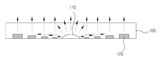
도 1은 본 발명에 따른 직하 방식 백라이트유닛용 도광판(100)의 제1실시예의 사용 상태를 나타낸 단면도이다.1 is a cross-sectional view showing a state of use of a first embodiment of a
도 1을 참조하면, 본 발명에 따른 직하 방식 백라이트유닛용 도광판(100)은 PMMA(Poly Methyl Methacrylate) 또는 PC(Poly Carbonat)로 제작된다.Referring to FIG. 1, the LGP 100 for a direct-type backlight unit according to the present invention is made of PMMA (Poly Methyl Methacrylate) or PC (Poly Carbonate).
바람직하게는, 본 발명에 따른 직하 방식 백라이트유닛용 도광판(100)은 JIS K7361-1 측정법으로 측정한 전광선투과율(Tt) 90% 이상, JIS K7136 측정법으로 측정한 담가(haze) 0.5% 미만의 PMMA(Poly Methyl Methacrylate) 또는 PC(Poly Carbonat)로 제작된다.Preferably, the
본 발명에 따른 직하 방식 백라이트유닛용 도광판(100)은 밑면 중 광 조사영역의 직하 지점에 위치하는 광원(예컨대, LED)과의 사이 부분에 광원(예컨대, LED)과 정해진 거리의 에어갭(Air-gap)을 형성하는 제1 요부(110)가 형성되어 있다.The
본 발명에 따른 직하 방식 백라이트유닛용 도광판(100)은 상기 제1 요부(110)를 중심으로 좌우 양방향으로 멀어질수록 높이가 비례적으로 높아지는 적어도 1개 이상의 제2 요부(120)가 형성되어 있다.The
본 발명에 따른 직하 방식 백라이트유닛용 도광판(100)에 있어서, 상기 제1 요부(110)는 구형 혹은 반구형 혹은 아치형 중 어느 하나로 형성하는 것이 바람직하다.In the
도 1에서는 본 발명에 따른 직하 방식 백라이트유닛용 도광판(100)의 제1실시예로서, 아치형의 제1 요부(110)를 중심으로 삼각추형으로 형성된 다수의 제2 요부(120)를 예시하고 있다.FIG. 1 illustrates a plurality of second recessed
참고로, 도 2에서는 본 발명에 따른 직하 방식 백라이트유닛용 도광판(100)의 제2실시예로서, 아치형의 제1 요부(110)를 중심으로 원추형으로 형성된 다수의 제2 요부(120)를 예시하고 있다.2 illustrates a second embodiment of a
참고로, 도 3에서는 본 발명에 따른 직하 방식 백라이트유닛용 도광판(100)의 제3실시예로서, 아치형의 제1 요부(110)를 중심으로 사각추형으로 형성된 다수의 제2 요부(120)를 예시하고 있다.Referring to FIG. 3, a third embodiment of a
참고로, 도 4에서는 본 발명에 따른 직하 방식 백라이트유닛용 도광판(100)의 제4실시예로서, 아치형의 제1 요부(110)를 중심으로 반구형으로 형성된 다수의 제2 요부(120)를 예시하고 있다.4 shows a fourth embodiment of a
참고로, 도 5에서는 본 발명에 따른 직하 방식 백라이트유닛용 도광판(100)의 제2실시예로서, 아치형의 제1 요부(110)를 중심으로 마킹 도트(marking dot)로 형성된 다수의 제2 요부(120)를 예시하고 있다. 상기 마킹 도트는 레이저방식 도트 마킹기 또는 프린트방식 도트 마킹기를 사용하여 형성하는 것이 바람직하다.5, a second embodiment of a
상기와 같이 구성되는 본 발명에 따른 직하 방식 백라이트유닛용 도광판(100)은 다음과 같이 작동한다.The
도 1에 나타낸 바와 같이, 본 발명에 따른 직하 방식 백라이트유닛용 도광판(100)은 PMMA(Poly Methyl Methacrylate) 또는 PC(Poly Carbonat)를 사용하여 제작된 것으로서, 직하 방식 백라이트유닛의 광원으로 사용되는 다수개의 LED(210)로 구성된 다수개의 LED 어레이가 설치된 기판(예컨대, PCB)(200) 상부에 설치된다.As shown in FIG. 1, the LGP 100 for a direct-type backlight unit according to the present invention is manufactured by using PMMA (Poly Methyl Methacrylate) or PC (Poly Carbonate) (E.g., a PCB) 200 on which a plurality of LED
이 경우, 상기 기판(예컨대, PCB)(200)과 도광판(100) 사이에는 통상 반사시트가 개재되는 것이 바람직하지만, 도 1에서는 본 발명에 따른 직하 방식 백라이트유닛용 도광판(100)의 작동을 자세히 설명하기 위하여 반사시트의 도시를 생략하였다.In this case, it is preferable that a reflective sheet is usually interposed between the substrate (e.g., PCB) 200 and the
도 1의 화살표로 나타낸 바와 같이, 본 발명에 따른 직하 방식 백라이트유닛용 도광판(100)의 밑면 중, 광 조사영역의 직하 지점에 위치하는 LED(210)와의 사이 부분에 LED(210)와 정해진 거리의 에어갭(Air-gap)을 형성하도록 형성된 아치형의 제1 요부(110)는 LED(210)로부터 방출되는 빛을 받아들여 본 발명에 따른 직하 방식 백라이트유닛용 도광판(100)의 표면을 통해 빛을 균일하게 분포시킨다.1, an
이때, 상기 제1 요부(110)는 화살표로 나타낸 바와 같이, 도광판(100)의 표면 방향과 상기 제2 요부(120)가 있는 좌우 양방향으로 분포된다.At this time, the first
또한, 상기 아치형의 제1 요부(120)를 중심으로 좌우 양방향으로 멀어질수록 높이가 비례적으로 높아지도록 삼각추형으로 형성된 다수의 제2 요부(120)는 화살표로 나타낸 바와 같이, 상기 아치형의 제1 요부(110)로부터 분포되는 빛을 삼각추의 경사면을 통해 도광판(100)의 표면 방향으로 반사시켜 균일하게 분포시킨다.A plurality of second
이처럼, 본 발명에 따른 직하 방식 백라이트유닛용 도광판(100)은 제1 요부(110)와 제2 요부(120)를 통해 LED(210)로부터 방출되는 빛을 받아들인 후, 그 표면에 형성된 일정 면적과 모양을 가진 패턴을 통해 액정표시장치(LCD)의 화면 표시 영역에 걸쳐 빛을 균일하게 분포시켜 준다.As described above, the
상기한 바에서 알 수 있듯이, 본 발명에 따른 직하 방식 백라이트유닛용 도광판(100)은 PMMA(Poly Methyl Methacrylate) 또는 PC(Poly Carbonat)를 사용하여 제작되고 밑면에 형성된 아치형의 제1 요부(110)에 LED(210)와 정해진 거리의 에어갭(Air-gap)을 형성하고 상기 아치형의 제1 요부(110)의 좌우 양방향으로 형성된 다수의 삼각추형의 제2 요부(120)가 LED(210)로부터 방출되는 빛을 받아들여 그 표면을 통해 빛을 균일하게 분포시켜 주기 때문에, LED(210)로부터 방출되는 빛이 충분히 균일하게 광 조사영역에 확산하게 하기 위해서 도광판의 두께를 늘릴 필요가 없으며, 이로 인해 직하 방식 백라이트유닛의 두께를 더욱더 슬림화할 수 있다.As can be seen from the above description, the
이상에서 설명한 본 발명에 따른 직하 방식 백라이트유닛용 도광판은 상기한 실시예에 한정되지 않고, 이하의 특허청구범위에서 청구하는 본 발명의 요지를 벗어남이 없이 본 발명이 속하는 분야에서 통상의 지식을 가진 자라면 누구든지 다양하게 변경하여 실시할 수 있는 범위까지 그 기술적 정신이 있다.The light guide plate for a direct-type backlight unit according to the present invention is not limited to the above-described embodiments, and various modifications and changes may be made without departing from the spirit and scope of the present invention, There is a technical spirit to the extent that anyone can make various changes.
100: 도광판
110: 제1 요부
120: 제2 요부
200: 기판
210: LED100: light guide plate 110: first prism
120: second recess 200: substrate
210: LED
Claims (3)
Priority Applications (2)
| Application Number | Priority Date | Filing Date | Title |
|---|---|---|---|
| KR1020160076553A KR20170142681A (en) | 2016-06-20 | 2016-06-20 | Light guide panel for the direct type BLU |
| PCT/KR2017/003757 WO2017222155A1 (en) | 2016-06-20 | 2017-04-06 | Light guide plate for direct type backlight unit |
Applications Claiming Priority (1)
| Application Number | Priority Date | Filing Date | Title |
|---|---|---|---|
| KR1020160076553A KR20170142681A (en) | 2016-06-20 | 2016-06-20 | Light guide panel for the direct type BLU |
Publications (1)
| Publication Number | Publication Date |
|---|---|
| KR20170142681A true KR20170142681A (en) | 2017-12-28 |
Family
ID=60783528
Family Applications (1)
| Application Number | Title | Priority Date | Filing Date |
|---|---|---|---|
| KR1020160076553A KR20170142681A (en) | 2016-06-20 | 2016-06-20 | Light guide panel for the direct type BLU |
Country Status (2)
| Country | Link |
|---|---|
| KR (1) | KR20170142681A (en) |
| WO (1) | WO2017222155A1 (en) |
Cited By (2)
| Publication number | Priority date | Publication date | Assignee | Title |
|---|---|---|---|---|
| CN112639358A (en) * | 2018-09-03 | 2021-04-09 | 昕诺飞控股有限公司 | Reflector and starting sheet for forming reflector |
| US11314013B2 (en) | 2019-06-12 | 2022-04-26 | Samsung Display Co., Ltd. | Backlight unit and display device having the same |
Families Citing this family (1)
| Publication number | Priority date | Publication date | Assignee | Title |
|---|---|---|---|---|
| CN108845461B (en) * | 2018-08-31 | 2023-06-30 | 武汉华星光电技术有限公司 | Backlight module and liquid crystal display device |
Family Cites Families (5)
| Publication number | Priority date | Publication date | Assignee | Title |
|---|---|---|---|---|
| KR20080001775A (en) * | 2006-06-30 | 2008-01-04 | 주식회사 한광옵토 | Light guide panel, back light unit using the same and method for manufacturing the same |
| KR101555340B1 (en) * | 2008-11-05 | 2015-09-30 | 삼성디스플레이 주식회사 | Back light assembly and liquid crystal display having the same |
| KR101597574B1 (en) * | 2009-06-15 | 2016-02-25 | 엘지전자 주식회사 | Module for light guide plate and LED back-light unit using the same |
| KR20120043600A (en) * | 2010-10-26 | 2012-05-04 | 엘지디스플레이 주식회사 | Backlight unit |
| JP2015115128A (en) * | 2013-12-10 | 2015-06-22 | 株式会社Dsコーポレーション | Reflection plate for backlight of flat display device |
-
2016
- 2016-06-20 KR KR1020160076553A patent/KR20170142681A/en not_active Application Discontinuation
-
2017
- 2017-04-06 WO PCT/KR2017/003757 patent/WO2017222155A1/en active Application Filing
Cited By (3)
| Publication number | Priority date | Publication date | Assignee | Title |
|---|---|---|---|---|
| CN112639358A (en) * | 2018-09-03 | 2021-04-09 | 昕诺飞控股有限公司 | Reflector and starting sheet for forming reflector |
| CN112639358B (en) * | 2018-09-03 | 2023-07-14 | 昕诺飞控股有限公司 | Reflector and starting sheet for forming the reflector |
| US11314013B2 (en) | 2019-06-12 | 2022-04-26 | Samsung Display Co., Ltd. | Backlight unit and display device having the same |
Also Published As
| Publication number | Publication date |
|---|---|
| WO2017222155A1 (en) | 2017-12-28 |
Similar Documents
| Publication | Publication Date | Title |
|---|---|---|
| US8300175B2 (en) | Lighting device having reflecting parts and liquid crystal display device using the same | |
| EP2600188A1 (en) | Light guide plate and backlight module | |
| US8550668B2 (en) | Light control member with intersecting groups of parallel prisms, and light-emitting device using such member | |
| KR101426600B1 (en) | A light scattering lens for planar light source device of liquid crystal displays | |
| KR20190021522A (en) | Light guide plate and backlight unit having the same | |
| KR20170142688A (en) | Light guide panel for the direct type BLU and resin composite for the light guide panel | |
| US7766533B2 (en) | Illumination module, and a display and general lighting apparatus using the same | |
| US20070223250A1 (en) | Light guide plate, light deflecting element configuration and surface light source device | |
| KR20170142681A (en) | Light guide panel for the direct type BLU | |
| KR101476002B1 (en) | A light scattering lens for planar light source device of liquid crystal displays | |
| US8908123B2 (en) | Direct-light type backlight module and liquid crystal display | |
| US11175533B2 (en) | Light redirecting film, backlight, and display system | |
| KR101798599B1 (en) | Luminous flux control member and back light unit using the same | |
| KR100918873B1 (en) | Direct lighting type backlight unit using led lamps | |
| JP2010146986A (en) | Lens for illumination, light-emitting device, plane light source, and liquid crystal display | |
| KR20100009827A (en) | Light guide panel using polygon prism diffusing structures for lcd back light unit and lcd backlight unit thereby | |
| KR101039322B1 (en) | Side light-emitting type back light unit | |
| KR20070006364A (en) | The backlight unit of a liquid crystal display device and a light source | |
| KR20070006359A (en) | The backlight unit of a liquid crystal display device and a light source | |
| KR101231714B1 (en) | Direct type backlight unit having improved lamp mura | |
| KR20180087116A (en) | Luminous flux control member and back light unit using the same | |
| KR20060118111A (en) | The backlight unit of a liquid crystal display device and a hologram sheet | |
| KR20150002969A (en) | Light-diffuser unit | |
| KR100625436B1 (en) | The backlight unit of a liquid crystal display device | |
| KR100920810B1 (en) | Scratch-resistant light collecting sheet and back light unit having the same |
Legal Events
| Date | Code | Title | Description |
|---|---|---|---|
| A201 | Request for examination | ||
| E902 | Notification of reason for refusal | ||
| E601 | Decision to refuse application |