JP2010146986A - Lens for illumination, light-emitting device, plane light source, and liquid crystal display - Google Patents
Lens for illumination, light-emitting device, plane light source, and liquid crystal display Download PDFInfo
- Publication number
- JP2010146986A JP2010146986A JP2008326158A JP2008326158A JP2010146986A JP 2010146986 A JP2010146986 A JP 2010146986A JP 2008326158 A JP2008326158 A JP 2008326158A JP 2008326158 A JP2008326158 A JP 2008326158A JP 2010146986 A JP2010146986 A JP 2010146986A
- Authority
- JP
- Japan
- Prior art keywords
- light
- optical axis
- light emitting
- light source
- radiated
- Prior art date
- Legal status (The legal status is an assumption and is not a legal conclusion. Google has not performed a legal analysis and makes no representation as to the accuracy of the status listed.)
- Pending
Links
Images


Landscapes
- Planar Illumination Modules (AREA)
- Led Device Packages (AREA)
- Liquid Crystal (AREA)
Abstract
【課題】光源の指向性をより広くすることのできる照明用レンズを提供する。
【解決手段】照明用レンズ1は、入射面11および出射面12を有している。出射面12は、光軸A上の頂点に向かって凸となる第1出射面121、第1出射面121の周縁部から外側に広がる第2出射面122とを有している。第1出射面121は、光軸A上の光源位置である基点Pから放射されて第1出射面121に到達する放射光のうち光軸Aからの角度が所定角度以上の放射光を、第1回目の到達点で全反射した後に、第2回目の到達点で屈折させて被照射面3に到達させる、形状を有している。第2出射面122は、基点Pから放射されて第2出射面122に到達する放射光をその到達点で屈折させて被照射面3に到達させる形状を有している。第2出射面122は、d/p<0.4の領域では、0.2<cosθ1・cos2θ2<0.98を満足する。
【選択図】図1Provided is an illumination lens capable of further widening the directivity of a light source.
An illumination lens has an entrance surface and an exit surface. The exit surface 12 has a first exit surface 121 that is convex toward the apex on the optical axis A, and a second exit surface 122 that spreads outward from the peripheral edge of the first exit surface 121. The first emission surface 121 emits radiated light whose angle from the optical axis A is greater than or equal to a predetermined angle out of the radiated light radiated from the base point P that is the light source position on the optical axis A and reaches the first emission surface 121. After total reflection at the first arrival point, the shape is refracted at the second arrival point to reach the irradiated surface 3. The second emission surface 122 has a shape in which radiated light radiated from the base point P and reaches the second emission surface 122 is refracted at the arrival point and reaches the irradiated surface 3. The second emission surface 122 satisfies 0.2 <cos θ 1 · cos 2 θ 2 <0.98 in the region of d / p <0.4.
[Selection] Figure 1
Description
本発明は、例えば発光ダイオード等の光源の指向性を広くする照明用レンズ、およびこの照明用レンズを用いた照明装置に関する。さらに、本発明は、複数の照明装置を備える面光源、およびこの面光源がバックライトとして液晶パネル後方に配置された液晶ディスプレイ装置に関する。 The present invention relates to an illumination lens that widens the directivity of a light source such as a light emitting diode, and an illumination device using the illumination lens. Furthermore, the present invention relates to a surface light source including a plurality of illumination devices, and a liquid crystal display device in which the surface light source is disposed behind a liquid crystal panel as a backlight.
従来の大型の液晶ディスプレイ装置のバックライトでは、冷陰極管が液晶パネル直下に多数配置され、これらの冷陰極管が拡散板や反射板等の部材と共に使われていた。近年では、バックライトの光源として発光ダイオードが使用されるようになっている。発光ダイオードは近年効率が向上し、蛍光灯に変わる消費電力の少ない光源として期待されている。また液晶ディスプレイ装置用の光源としては映像に応じて発光ダイオードの明暗を制御することで液晶ディスプレイ装置の消費電力を下げることができる。 In the backlight of a conventional large-sized liquid crystal display device, a large number of cold cathode tubes are arranged directly under the liquid crystal panel, and these cold cathode tubes are used together with members such as a diffusion plate and a reflecting plate. In recent years, a light emitting diode has been used as a light source of a backlight. Light-emitting diodes have been improved in efficiency in recent years, and are expected as light sources with low power consumption instead of fluorescent lights. As a light source for the liquid crystal display device, the power consumption of the liquid crystal display device can be reduced by controlling the brightness of the light emitting diodes according to the image.
液晶ディスプレイ装置の発光ダイオードを光源とするバックライトでは、冷陰極管の代わりに多数の発光ダイオードを配置することとなる。多数の発光ダイオードを用いることでバックライト表面で均一な明るさを得ることができるが、発光ダイオードが多数必要で安価にできない問題があった。1個の発光ダイオードの出力を大きくし、発光ダイオードの使用する個数を減らす取り組みがなされており、例えば特許文献1では、少ない個数の発光ダイオードでも均一な面光源が得られるようにするレンズが提案されている。
少ない個数の発光ダイオードで均一な面光源を得るためには、1個の発光ダイオードが照明する被照明領域を大きくする必要がある。すなわち発光ダイオードからの光を拡張して指向性を広くすることが必要である。このために特許文献1では、チップ状の発光ダイオードの指向性を制御する平面視で円形状のレンズを発光ダイオードの上に配置している。このレンズの形状は、光を出射させる出射面における光軸近傍部分が凹面となっており、その外側部分が凹面と連続する凸面となっている。
In order to obtain a uniform surface light source with a small number of light emitting diodes, it is necessary to enlarge the illuminated area illuminated by one light emitting diode. That is, it is necessary to expand the light from the light emitting diode to widen the directivity. Therefore, in
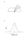
発光ダイオードでは、発光ダイオードのチップの正面方向に最も多くの光が発光しており、特許文献1に開示されたレンズでは、図17(a)に示すように、光軸近傍の凹面でチップからの正面方向に向かう光を屈折により発散させている。これにより、図17(b)に示すように、被照射面における光軸近傍の照度を抑えて広がりのある照度分布にすることができる。
In the light emitting diode, the most light is emitted in the front direction of the chip of the light emitting diode, and in the lens disclosed in
ところで、発光ダイオードの発光は点ではなく、ある程度の発光領域を持っている。発光領域の周辺部より発光した光は、発光領域の中心部より発光した光とは違う経路をとる。図17(a)では、発光領域の中心部より発光した光の経路を実線で示し、発光領域の周辺部より発光した光の経路を波線で示している。 By the way, the light emission of the light emitting diode is not a point but has a certain light emission region. The light emitted from the periphery of the light emitting region takes a different path from the light emitted from the central portion of the light emitting region. In FIG. 17A, the path of light emitted from the central portion of the light emitting region is indicated by a solid line, and the path of light emitted from the peripheral portion of the light emitting region is indicated by a wavy line.
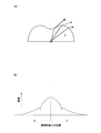
照度分布をより広がりのあるものにするには、光軸近傍の凹面の曲率半径を小さくすることが考えられる。このようにすれば、発光領域中心部からの光の凹面への入射角が大きくなり、この光を図18(a)中に実線で示すように周囲へ大きく屈折させることができる。しかしながら、発光領域周辺部からの光は図18(a)中に波線で示すように凹面への入射角が局所的に大きくなりすぎて全反射を起こすようになる。このため、図18(b)に示すように、被照射面上の照度は局所的に低下し、リング状に暗所が形成される。その結果、面光源としたときに輝度ムラが生じるようになる。このように特許文献1に記載のレンズでは、発光領域周辺部の光の全反射の影響で光源の指向性を広くするには限界がある。
In order to make the illuminance distribution wider, it is conceivable to reduce the radius of curvature of the concave surface near the optical axis. In this way, the incident angle of the light from the central portion of the light emitting region to the concave surface is increased, and this light can be refracted greatly to the surroundings as shown by the solid line in FIG. However, the light from the periphery of the light emitting region causes total reflection because the incident angle to the concave surface is locally increased as shown by the wavy line in FIG. For this reason, as shown in FIG.18 (b), the illumination intensity on a to-be-irradiated surface falls locally, and a dark place is formed in a ring shape. As a result, luminance unevenness occurs when the surface light source is used. As described above, the lens disclosed in
本発明は、光源の指向性をより広くすることのできる照明用レンズを提供するとともに、この照明用レンズを含む発光装置、面光源、および液晶ディスプレイ装置を提供することを目的とする。 It is an object of the present invention to provide an illumination lens capable of further widening the directivity of a light source, and to provide a light emitting device, a surface light source, and a liquid crystal display device including the illumination lens.
前記目的を達成するために、本発明の発明者は、発光ダイオードのチップの正面方向に行く、強い光を如何に周囲に配光するかが指向性をより広くするために重要であると考え、意図的に全反射を使って発光ダイオードのチップの正面方向に行く光を周囲に配光することを思い付いた。本発明はこのような観点からなされたものである。 In order to achieve the above object, the inventor of the present invention considers that how to distribute strong light around the light emitting diode chip in the front direction is important for widening the directivity. I intentionally came up with the idea of using total internal reflection to distribute the light going to the front of the LED chip to the surroundings. The present invention has been made from such a viewpoint.
すなわち、本発明は、所定の光軸間距離pで配置され、光源からの光を拡張して被照射面に照射する照明用レンズであって、光源からの光が入射する入射面と、入射した光を出射させる、光軸に対して軸対称な出射面と、を備え、前記出射面は、前記光軸上の頂点に向かって凸となる第1出射面と、この第1出射面の周縁部から外側に広がりながら凸面を形成する第2出射面と、を有し、前記第1出射面は、前記光軸上の前記光源の位置を基点としたときに、前記基点から放射されて当該第1出射面に到達する放射光のうち前記光軸からの角度が所定角度以上の放射光を、放射光が最初に到達する第1回目の到達点で全反射した後に、全反射された放射光が到達する第2回目の到達点で屈折させて前記被照射面に到達させる、形状を有しており、前記第2出射面は、前記基点から放射されて当該第2出射面に到達する放射光をその到達点で屈折させて前記被照射面に到達させる形状を有しており、前記基点から放射される放射光の光線と前記光軸とのなす角度をθ1、前記基点からθ1の角度で放射され、前記第2出射面で屈折した放射光の光線と前記光軸とのなす角度をθ2、前記基点からθ1の角度で放射され、前記第2出射面で屈折した放射光が前記被照射面に到達する位置から前記光軸までの距離をdとしたときに、前記第2出射面は、d/p<0.4の領域では、以下の式
0.2<cosθ1・cos2θ2<0.98
を満足する、照明用レンズを提供する。
That is, the present invention is an illumination lens that is arranged at a predetermined distance p between optical axes and that irradiates a surface to be irradiated by expanding light from a light source. An output surface that is axially symmetric with respect to the optical axis, and the output surface is convex toward the apex on the optical axis, and the first output surface A second emission surface that forms a convex surface while spreading outward from the periphery, and the first emission surface is emitted from the base point when the position of the light source on the optical axis is the base point. Of the radiated light reaching the first emission surface, the radiated light whose angle from the optical axis is equal to or larger than a predetermined angle is totally reflected after being totally reflected at the first arrival point where the radiated light first arrives. It has a shape that is refracted at the second arrival point where the radiated light reaches and reaches the irradiated surface. The second emission surface has a shape that radiates light from the base point and reaches the second output surface by refracting the radiated light reaching the second output surface and radiates from the base point. The angle formed between the light beam of the emitted light and the optical axis is θ 1 , and the angle formed between the light beam radiated at the angle θ 1 from the base point and refracted at the second exit surface is formed with the optical axis. theta 2, emitted at theta 1 angle from the base point, the distance from the position where radiation refracted by the second exit surface reaches the surface to be illuminated to the optical axis is taken as d, the second In the region where d / p <0.4, the emission surface has the following formula: 0.2 <cos θ 1 · cos 2 θ 2 <0.98
Provide an illumination lens that satisfies the above requirements.
また、本発明は、光を放射する発光ダイオードと、前記発光ダイオードからの光を拡張して被照射面に照射する照明用レンズと、を備える発光装置であって、前記照明用レンズは、上記の照明用レンズである、発光装置を提供する。 Further, the present invention is a light emitting device comprising: a light emitting diode that emits light; and an illumination lens that expands light from the light emitting diode and irradiates a surface to be irradiated. Provided is a light-emitting device that is an illumination lens.
さらに、本発明は、平面的に配置された複数の発光装置と、前記複数の発光装置を覆うように配置され、前記複数の発光装置から一方面に照射された光を他方面から拡散した状態で放射する拡散板と、を備える面光源であって、前記複数の発光装置のそれぞれは、上記の発光装置である、面光源を提供する。 Further, the present invention provides a plurality of light emitting devices arranged in a plane and a state in which light emitted from one surface of the plurality of light emitting devices is diffused from the other surface. A surface light source comprising: a diffuser plate that radiates at a plurality of light emitting devices, wherein each of the plurality of light emitting devices provides the surface light source.
また、本発明は、液晶パネルと、前記液晶パネルの裏側に配置された上記の面光源と、を備える液晶ディスプレイ装置を提供する。 Moreover, this invention provides a liquid crystal display device provided with a liquid crystal panel and said surface light source arrange | positioned at the back side of the said liquid crystal panel.
上記の構成によれば、第1出射面は、光源の発光領域中央部からの光をいったん全反射させた後に出射させる凸面になっている。このため、光源の発光領域周辺部からの光も第1出射面で全反射した後に被照射面に到達するようになる。すなわち、第1出射面によれば、第1出射面に到達する光の略全量を被照射面におけるレンズの光軸を中心とするより広い領域に照射することができる。一方、凸面を形成する第2出射面によれば、第2出射面に到達する光を被照射面におけるレンズの光軸から離れた領域に照射することができる。従って、本発明によれば、従来のような制約を伴うことなく、換言すれば光源から正面方向に行く強い光を有効に配光して、光源の指向性をより広くすることができる。 According to said structure, the 1st output surface is a convex surface which makes it light-emitted, after once totally reflecting the light from the light emission area center part of a light source. For this reason, the light from the periphery of the light emitting region of the light source also reaches the irradiated surface after being totally reflected by the first emission surface. That is, according to the first emission surface, it is possible to irradiate a wider area centering on the optical axis of the lens on the irradiated surface with substantially the entire amount of light reaching the first emission surface. On the other hand, according to the 2nd output surface which forms a convex surface, the light which reaches the 2nd output surface can be irradiated to the field far from the optical axis of the lens in an irradiated surface. Therefore, according to the present invention, the directivity of the light source can be broadened by effectively distributing strong light traveling from the light source in the front direction without any conventional restrictions.
さらに本発明では、第2出射面が特定の条件を満たしているので、光源からの光をより広く配光することができる。従って、照明用レンズを所定の光軸間距離pで被照射面に平行な方向に平面的に複数配置したときには、光軸間距離pを大きくするとともに個々のレンズによる照射範囲を広くしても被照射面を均一に照明することができる。 Furthermore, in this invention, since the 2nd output surface satisfy | fills specific conditions, the light from a light source can be distributed more widely. Therefore, when a plurality of illumination lenses are arranged in a plane in a direction parallel to the irradiated surface with a predetermined optical axis distance p, the optical axis distance p can be increased and the irradiation range of each lens can be increased. The illuminated surface can be illuminated uniformly.
(実施の形態1)
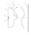
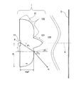
本発明の実施の形態1に係る照明用レンズついて、図面を参照しつつ説明する。図1は、実施の形態1に係る照明用レンズ1の構成図である。照明用レンズ1は、指向性を有する光源(図1では省略)と被照射面3との間に配置され、光源からの光を拡張して被照射面3に照射するものである。すなわち、照明用レンズ1によって光源の指向性が広くされる。被照射面3の照度分布は、照明用レンズ1の設計上の中心線である光軸A上が最大で周囲に行くほど略単調に減少する。なお、光源と照明用レンズ1とは、互いの光軸が合致するように配置される。また、実際には、図13に示すように、複数の照明用レンズ1が所定の光軸間距離pで被照射面3に平行な方向に平面的に配置される。ここで、光軸間距離pとは、最も近接する照明用レンズ1同士の光軸間距離のことであり、例えば、照明用レンズ1がマトリクス状に配置される場合は、照明用レンズ1の縦横のピッチのうち小さい方(それらが同じであってもよい)のピッチが光軸間距離pとなり、照明用レンズ1が千鳥状に配置される場合は、照明用レンズ1が最小間隔で並ぶ列におけるピッチが光軸間距離pとなる。
(Embodiment 1)
The illumination lens according to
具体的に、照明用レンズ1は、光源からの光が入射する入射面11と、入射した光を出射させる出射面12とを有している。出射面12は光軸Aに対して軸対称である。照明用レンズ1の平面視における輪郭は、光軸Aに対して軸対称である必要はない。入射面11は光軸Aに対して軸対称である必要はない。光源からの光は、入射面11から照明用レンズ1内に入射した後に出射面12から出射されて、被照射面3に到達する。光源から放射される光は、出射面12の作用で拡張され、被照射面3の広い範囲に到達するようになる。
Specifically, the
光源としては、例えば発光ダイオードを採用することができる。発光ダイオードは矩形板状のチップであることが多く、照明用レンズ1の入射面11も発光ダイオードに密着可能なように発光ダイオードの形状に合わせた形状とすることが好ましい。発光ダイオードは、照明用レンズ1の入射面11と接合剤を介して接していて、入射面11と光学的に接合されている。発光ダイオードは、通常は空気に触れないように封止樹脂で覆われているが、照明用レンズ1が封止樹脂の役割を果たすため、別途封止樹脂を配置する必要はない。従来の発光ダイオードの封止樹脂としては、エポキシ樹脂またはシリコンゴム等が用いられている。
As the light source, for example, a light emitting diode can be employed. The light-emitting diode is often a rectangular plate-shaped chip, and it is preferable that the
照明用レンズ1は、所定の屈折率を有する透明材料で構成される。透明材料の屈折率は、例えば1.4から1.5程度である。このような透明材料としては、エポキシ樹脂、シリコン樹脂、アクリル樹脂、ポリカーボネイト等の樹脂、またはシリコンゴム等のゴムを用いることができる。中でも、発光ダイオードの封止樹脂として用いられるエポキシ樹脂またはシリコンゴム等を用いることが好ましい。
The
出射面12は、光軸A上の頂点に向かって凸となる第1出射面121と、この第1出射面121の周縁部から外側に広がりながら凸面を形成する第2出射面122とからなる。入射面11から照明用レンズ1の内部に入射する光は大きな角度範囲を持っている。光軸Aからの角度が小さい光は第1出射面121に到達し、光軸Aからの角度が大きい光は第2出射面122に到達する。
The
次に、第1出射面121および第2出射面122の形状について説明する。そのために、まず基点Pを規定し、この基点Pから放射される放射光を観念する。ここで、基点Pとは、光軸A上の光源の位置のことであり、光源として発光ダイオードを採用した場合は光軸Aと発光ダイオードの正面である出射面との交点となる。すなわち、基点Pは、入射面11から上述した接合剤の厚み分だけ離れている。そして、基点Pから放射される放射光は、第1出射面121と第2出射面122の境界と基点Pとを結んだ線と光軸Aとのなす角度θbを境に第1出射面121と第2出射面122のそれぞれに到達する。
Next, the shapes of the
第1出射面121は、基点Pから放射されて第1出射面121に到達する放射光のうち光軸Aからの角度が所定角度θf(図5参照)以上の放射光を、放射光が最初に到達する第1回目の到達点131(図3参照)で全反射した後に、全反射された放射光が到達する第2回目の到達点132(図3参照)で屈折させて被照射面3に到達させる、形状を有している。このように第1出射面121に到達した、光軸Aからの角度が所定角度θf以上の基点Pからの放射光は、1回の全反射と1回の屈折作用を受けて、大きく進路を変更し、被照射面3に照射されるようになる。ここで、第1回目の到達点131と第2回目の到達点132は、光軸Aを挟んで反対側に位置することが好ましい。すなわち、第1回目の到達点131から第2回目の到達点132に至る光線は光軸と交差することが好ましい。
The
第1出射面121が基点Pからの放射光を全反射させる始角である所定角度θfは、第1出射面121に到達する基点Pからの放射光の殆どがいったん全反射されるように、略0度となっていてもよい。ここで、略0度とは、1度未満の角度をいう。これを実現するには、第1出射面121の頂点を鋭く尖らせればよい。このようにすれば、被照射面3における光軸Aの近傍部分に到達する光量を抑えて、光源からの光をより周囲に配光することができる。
The predetermined angle θf, which is the starting angle at which the
ただし、複数の発光ダイオードを用いて面光源を構成する場合は、所定角度θfを3〜7度とすることが好ましい。θfが3度未満だと被照射面3における光軸Aの近傍部分が暗くなりすぎ、θfが7度を超えると被照射面3における光軸Aの近傍部分が明るくなりすぎ、いずれの場合も面光源としたときに均一な照度分布を実現し難くなるからである。
However, when the surface light source is configured by using a plurality of light emitting diodes, the predetermined angle θf is preferably set to 3 to 7 degrees. If θf is less than 3 degrees, the portion near the optical axis A on the
さらに、所定角度θfが3〜7度である場合、第1出射面121は、基点Pから放射されて第1出射面121に到達する放射光のうち光軸Aからの角度が所定角度θf未満の放射光をその到達点133(図5参照)で屈折させて被照射面3に到達させる形状を有していることが好ましい。これを実現するには、第1出射面121の頂点近傍部分の曲率半径を大きくすればよい。このようにすれば、被照射面3における光軸Aの近傍部分を照明することができ、面光源としたときに面内での輝度ムラを少なくすることができる。
Further, when the predetermined angle θf is 3 to 7 degrees, the angle from the optical axis A among the radiated light radiated from the base point P and reaching the
なお、第1出射面121と第2出射面122の境界と基点Pとを結んだ線と光軸Aとのなす角度θb(これは第1出射面121の終角でもあり第2出射面122の始角でもある)は、15〜25度の範囲内にあることが好ましい。θbが15度未満の場合は、第1出射面121による効果が小さくなり、大きな拡散効果が得られない。θbが25度を超える場合は、被照射面3における光軸Aの近傍部分が明るくなりすぎる。
Note that an angle θb formed by a line connecting the boundary between the
一方、第2出射面122は、基点Pから放射されて第2出射面122に到達する放射光をその到達点14(図4参照)で屈折させて被照射面3に到達させる形状を有している。第2出射面122の外側に行くほど基点Pからの放射光と光軸Aとの角度は大きくなるが、放射光が第2出射面122に到達した到達点14での法線に対する放射線の光線の角度(後述するθ1−θ3)は第2出射面122に対する入射角であり、入射角が大きくなりすぎると全反射してしまう。全反射させないためには入射角を大きくさせないことが必要で、第2出射面122の形状は、光軸Aより遠くなるに従って、法線と光軸Aとの角度が大きくなるような形状、すなわち凸面になる。
On the other hand, the
なお、第2出射面122の形状は、次のようにも表すことができる。図1に示すように、基点Pから放射される放射光の光線B1と光軸Aとのなす角度をθ1、基点Pからθ1の角度で放射される放射光の光線B1と出射面12との交点Qにおける出射面12の法線Nと光軸Aとのなす角度をθ3、レンズの屈折率をn1、レンズの周囲の屈折率をn2とする。第2出射面122は、以下の式(1)
n1・sin(θ1−θ3)<n2・・・(1)
を満足する。式(1)は、第2出射面122の範囲を規定した式であり、第2出射面122の範囲を基点Pからの角度(極座標)で定義し、基点Pから放射された放射光が第2出射面122に到達したときに第2出射面122が光軸と平行であると仮定した時の全反射しない範囲を与えている。式(1)の左辺の値が式(1)の右辺の値以上になると、第2出射面122で全反射するようになる。
The shape of the
n 1 · sin (θ 1 −θ 3 ) <n 2 (1)
Satisfied. Expression (1) is an expression that defines the range of the second
さらに、本実施形態の第2出射面122は、基点Pからθ1の角度で放射され、第2出射面122で屈折した放射光の光線B2と光軸Aとのなす角度をθ2、基点Pからθ1の角度で放射され、第2出射面122で屈折した放射光が被照射面3に到達する位置から光軸Aまでの距離をd(図13参照)としたときに、d/p<0.4の領域では、以下の式(2)
0.2<cosθ1・cos2θ2<0.98・・・(2)
を満足する。式(2)は、第2出射面122の部分範囲を規定した式であり、第2出射面122から出射された光の分布範囲を定義している。式(2)中の「cosθ1・cos2θ2」が0.98以上になると、被照射面3における光軸A上の照度が高くなりすぎ、0.2以下になると、被照射面3における光軸A近傍の照度が増し、光源の指向性をあまり広げることができない。よって、式(2)を満足しなければ、光の配光分布に偏りを生じ、光源を光軸間距離pで配置した際に、被照射面3において照度ムラを生じてしまう。
Furthermore, the
0.2 <cos θ 1 · cos 2 θ 2 <0.98 (2)
Satisfied. Expression (2) is an expression that defines a partial range of the
さらに、第2出射面122の局所曲率は、60°<θ1<80°となる範囲で最大の極大値を有することが好ましい。第2出射面122の局所曲率がθ1≦60°となる範囲で最大の極大値を有する場合には、第2出射面122から出射する光を広範囲に配光できなくなり、80°≦θ1となる範囲で最大の極大値を有する場合には、被照射面において照度ムラを少なくする配光分布特性が得られなくなり、照度ムラの原因となるからである。
Furthermore, it is preferable that the local curvature of the
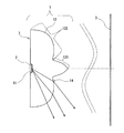
以上説明したように、第1出射面121は、図3中に実線で示すように光源の発光領域中央部からの光をいったん全反射させた後に出射させる凸面になっている。このため、図3中に波線で示すように光源の発光領域周辺部からの光も第1出射面121で全反射した後に被照射面3に到達するようになる。すなわち、第1出射面121によれば、第1出射面121に到達する光の略全量を被照射面3におけるレンズの光軸Aを中心とするより広い領域に照射することができる。一方、凸面を形成する第2出射面122によれば、第2出射面122に到達する光を被照射面3におけるレンズの光軸Aから離れた領域に照射することができる。従って、本実施の形態1の照明用レンズ1によれば、従来のような制約を伴うことなく、換言すれば光源から正面方向に行く強い光を有効に配光して、光源の指向性をより広くすることができる。
As described above, the
さらに、本実施の形態1の照明用レンズ1では、第2出射面122がd/p<0.4の領域で上記の式(2)を満足しているので、光源からの光をより広く配光することができる。従って、照明用レンズ1を所定の光軸間距離pで被照射面3に平行な方向に平面的に複数配置したときには、光軸間距離pを大きくするとともに個々のレンズ1による照射範囲を広くしても被照射面3を均一に照明することができる。
Furthermore, in the
なお、本発明の照明用レンズは、発光ダイオード以外の光源(例えば、レーザーまたは有機EL)にも適用可能である。 The illumination lens of the present invention can also be applied to a light source other than a light emitting diode (for example, a laser or an organic EL).
(実施の形態2)
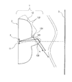
図2は、本発明の実施の形態2に係る発光装置7の構成図である。この発光装置7は、光を放射する発光ダイオード2と、発光ダイオード2からの光を拡張して被照射面3に照射する、実施の形態1で説明した照明用レンズ1とを備えている。
(Embodiment 2)
FIG. 2 is a configuration diagram of the light-emitting
発光ダイオード2は、照明用レンズ1の入射面11に接合剤により密着して配置され、光学的に接合されている。照明用レンズ1の出射面12から出射した光は被照射面3に到達し、被照射面3を照明する。
The
発光ダイオード2内での発光は指向性を持たない発光であるが、発光領域の屈折率は2.0以上であり、屈折率が低い領域に光が侵入すると、界面の屈折の影響で、界面の法線方向に最大の強度を持ち、法線方向から角度が大きくなるほど、光の強度は小さくなる。このように発光ダイオード2は指向性を持っており、広い範囲を照明するためには照明用レンズ1で指向性を広くすることが必要である。
The light emission in the
図3は発光装置7の光路図である。図3では光源からの光のうち小さな角度で出射して、第1出射面121に到達する光線の光路を説明する。発光ダイオード2から出射した光は入射面11を透過し、第1出射面121に到達する。第1の出射面121上で光が到達した位置を第1回目の到達点131とする。第1回目の到達点131では発光ダイオード2からの光は大きな入射角で第1出射面121に入射するため第1出射面121を透過することができず、すべて反射する。反射した光は光軸と交差し、再度第1出射面121に到達する。第1の出射面121上で再度光が到達した位置を第2回目の到達点132とする。第2回目の到達点132では第1回目の到達点131で反射された光は小さな入射角で第1出射面121に入射するため、屈折作用を受けながら第1出射面121を透過する。透過した光は被照射面3に到達する。
FIG. 3 is an optical path diagram of the
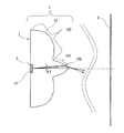
図4は発光装置7の光路図である。図4では光源からの光のうち大きな角度で出射して、第2出射面122に到達する光線の光路を説明する。発光ダイオード2から出射した光は入射面11を透過し、第2出射面122に到達する。第2出射面122では光線は屈折作用を受けて透過し、被照射面3に到達する。
FIG. 4 is an optical path diagram of the
図5は発光装置7の光路図である。図5では光源からの光のうち光軸近傍の小さな角度で出射して、第1出射面121に到達する光線の光路を説明する。発光ダイオード2から出射した光は入射面11を透過し、第1出射面121に到達する。第1出射面121では光線は屈折作用を受けて透過し、被照射面3に到達する。このように、第1出射面121の光軸近傍に入射した光が全反射せず、屈折作用を受けて透過して、被照射面3に到達することで、被照射面3における光軸近傍部分の照度が必要以上に暗くなることを防ぐことができる。
FIG. 5 is an optical path diagram of the
以下、本発明の具体的な数値例として、実施例1を示す。 Hereinafter, Example 1 is shown as a specific numerical example of the present invention.
(実施例1)
図6は、本発明の実施の形態2の実施例1に係る発光装置の構成図である。本実施例1は、0.5mm角の発光ダイオードを光源とし、指向性を広げることを目的とした設計例である。図6中のθ1は、光軸A上の光源位置(基点P)と出射面12上の任意の位置とを結んだ直線と光軸Aとの角度である。また、図6中のθ3は、前記出射面12上の任意の位置での出射面12の法線、換言すれば光軸A上の光源位置(基点P)からθ1の角度方向に放射された光が出射面12に到達する位置での出射面12の法線が、光軸Aとなす角度である。さらに、図6中のθ2は、光軸A上の光源位置(基点P)からθ1の角度方向に放射され、第2出射面122で屈折した光の光線と光軸Aとのなす角度である。また、図6中のsagYは、光軸A上の光源位置(基点P)から前記出射面12上の任意の位置まで光軸方向に測った距離である。
Example 1
FIG. 6 is a configuration diagram of a light-emitting device according to Example 1 of
次に具体的な数値を表1に示す。 Next, specific numerical values are shown in Table 1.
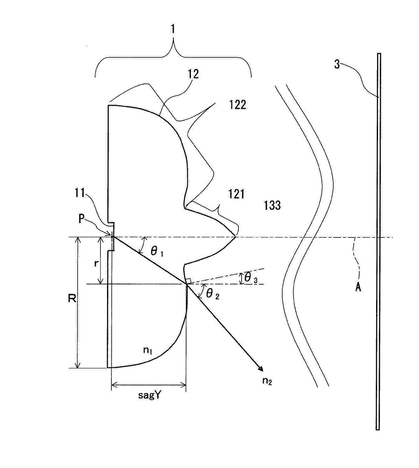
図7は、表1のθ1とsagYについてグラフ化したものである。 FIG. 7 is a graph of θ 1 and sagY in Table 1.
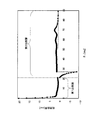
本具体例1では、レンズを屈折率1.41(n1=1.41)の材料で構成しており、出射面12は空気(n2=1)に面している。これを上記式(1)に代入すると、第2出射面122では、θ1−θ3が45.172度未満となる。ここで、図8に、r/Rとθ1−θ3の関係のグラフを示す。r/Rは、光軸Aから前記出射面12上の任意の位置までの入射面11に平行な方向の距離をレンズ最外半径で規格化した値である(r:光軸から前記出射面上の任意の位置までの入射面に平行な方向の距離、R:レンズ最外半径)。図8は、第2出射面122ではθ1−θ3が45.172度未満となっていて式(1)が満たされていることを示している。また、図8は、第1出射面121が光軸A上の光源位置(基点P)から放射された光を光軸A近傍以外で全反射する形状であることをも示している。
In this specific example 1, the lens is made of a material having a refractive index of 1.41 (n 1 = 1.41), and the
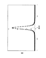
さらに、図9に、d/pとcosθ1・cos2θ2の関係のグラフを示す。上記式(2)は、第2出射面122ではd/p<0.4の領域でcosθ1・cos2θ2が0.2と0.98の範囲内にあることを規定しているが、図9はこれが満たされていることを示している。なお、本実施例1では、pを20mmに設定しており、発光ダイオード2から被照射面3までの距離D(図13参照)を8mmに設定している。
Further, FIG. 9 shows a graph of the relationship between d / p and cos θ 1 · cos 2 θ 2 . The above equation (2) stipulates that cos θ 1 · cos 2 θ 2 is in the range of 0.2 and 0.98 in the region of d / p <0.4 on the
また、図10に、θ1と局所曲率の関係のグラフを示す。図10から、第2出射面122の局所曲率は、θ1が約70度の位置で最大の極大値を有していることが分かる。すなわち、図10は、第2出射面122の局所曲率は、60°<θ1<80°となる範囲で最大の極大値を有することを示している。
FIG. 10 is a graph showing the relationship between θ 1 and local curvature. From FIG. 10, it can be seen that the local curvature of the
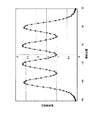
図11は、具体例1の発光装置(実施例1の照明用レンズと発光ダイオード)を配置し、発光ダイオードから8mm離れた位置に被照射面を配置したときの計算で求めた被照射面での照度分布を表す。図12は、図11のときと同じ発光ダイオードのみを配置し、発光ダイオードから8mm離れた位置に被照射面を配置したときの計算で求めた被照射面での照度分布を表す。図11と図12を比較すると、照明用レンズの効果で被照射面を広く照明できていることがわかる。
FIG. 11 shows an irradiated surface obtained by calculation when the light emitting device of Example 1 (illumination lens and light emitting diode of Example 1) is disposed and the irradiated surface is disposed at a
(実施の形態3)
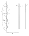
図13は、本発明の実施の形態3に係る面光源8の構成図である。この面光源8は、平面的に配置された、実施の形態2で説明した複数の発光装置7と、これらの発光装置7を覆うように配置された拡散板4とを備えている。なお、発光装置7は、マトリクス状に配置されていてもよいし、千鳥状に配置されていてもよい。
(Embodiment 3)
FIG. 13 is a configuration diagram of the
発光装置7は、拡散板4の一方面4aに光を照射する。すなわち、拡散板4の一方面4aは、実施の形態1および実施の形態2で説明した被照射面3となっている。拡散板4は、一方面4aに照射された光を他方面4bから拡散された状態で放射する。個々の発光装置7からは拡散板4の一方面4aに広い範囲で均一化された照度の光が照射され、この光が拡散板4で拡散されることにより、面内での輝度ムラが少ない面光源ができる。
The
ここで、発光ダイオード2から拡散板4の一方面4aである被照射面3までの距離Dと照明用レンズ1の光軸間距離pの関係については、0.3<D/p<0.5となっていることが好ましい。
Here, regarding the relationship between the distance D from the
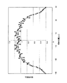
図14は、実施例1の照明用レンズと発光ダイオードからなる発光装置を20mmピッチで一直線上に4つ配置し、発光ダイオードから8mm離れた位置に拡散板を配置したときの計算で求めた拡散板入射面(発光装置側の一方面)での照度分布を表す。照度分布に細かな波が見られるが照度計算を実行する上で、評価する光線数が不足しているためである。図15は、発光ダイオードのみを20mmピッチで一直線に4つ配置し、発光ダイオードから8mm離れた位置に拡散板を配置したときの計算で求めた拡散板入射面での照度分布を表す。図14と図15を比較すると、照明用レンズの効果で拡散板入射面を均一に照明できていることがわかる。
FIG. 14 shows the diffusion obtained by calculation when four light-emitting devices comprising the illumination lens and the light-emitting diode of Example 1 are arranged in a straight line at a pitch of 20 mm and a diffusion plate is arranged at a
(実施の形態4)
図16は、本発明の実施の形態4に係る液晶ディスプレイ装置の構成図である。この液晶ディスプレイ装置は、液晶パネル5と、液晶パネル5の裏側に配置された、実施の形態3で説明した面光源8とを備えている。
(Embodiment 4)
FIG. 16 is a configuration diagram of a liquid crystal display device according to Embodiment 4 of the present invention. This liquid crystal display device includes a
発光ダイオード2と照明用レンズ1で構成される発光装置7が平面的に複数配置され、これらの発光装置7によって拡散板4が照明される。拡散板4の裏面(一方面)は、照度が均一化された光が照射され、この光が拡散板4によって拡散されて液晶パネル5が照明される。
A plurality of light emitting
なお、図16に示すように、液晶パネル5と面光源8との間には拡散シート、プリズムシート等のシート41が配置されているとともに、発光装置7が存在しない部分には拡散反射板6が配置されていることが好ましい。発光装置7からの光は、拡散板4で散乱されて、発光装置側へ戻ったり拡散板4を透過したりする。発光装置側へ戻って拡散反射板6に入射する光は、拡散反射板6で反射されて、拡散板4に再度入射する。拡散板4を透過した光は、シート41でさらに拡散されて、液晶パネル5を照明する。
As shown in FIG. 16, a
1 照明用レンズ
11 入射面
12 出射面
121 第1出射面
122 第2出射面
131 第1回目の到達点
132 第2回目の到達点
133 到達点
14 到達点
2 発光ダイオード(光源)
3 被照射面
4 拡散板
41 拡散シートまたはプリズムシート
5 液晶パネル
6 拡散反射板
7 発光装置
8 面光源
A 光軸
B1,B2 光線
N 法線
P 基点
Q 交点
DESCRIPTION OF
3 Light irradiated surface 4
Claims (7)
光源からの光が入射する入射面と、入射した光を出射させる、光軸に対して軸対称な出射面と、を備え、
前記出射面は、前記光軸上の頂点に向かって凸となる第1出射面と、この第1出射面の周縁部から外側に広がりながら凸面を形成する第2出射面と、を有し、
前記第1出射面は、前記光軸上の前記光源の位置を基点としたときに、前記基点から放射されて当該第1出射面に到達する放射光のうち前記光軸からの角度が所定角度以上の放射光を、放射光が最初に到達する第1回目の到達点で全反射した後に、全反射された放射光が到達する第2回目の到達点で屈折させて前記被照射面に到達させる、形状を有しており、
前記第2出射面は、前記基点から放射されて当該第2出射面に到達する放射光をその到達点で屈折させて前記被照射面に到達させる形状を有しており、
前記基点から放射される放射光の光線と前記光軸とのなす角度をθ1、前記基点からθ1の角度で放射され、前記第2出射面で屈折した放射光の光線と前記光軸とのなす角度をθ2、前記基点からθ1の角度で放射され、前記第2出射面で屈折した放射光が前記被照射面に到達する位置から前記光軸までの距離をdとしたときに、
前記第2出射面は、d/p<0.4の領域では、以下の式
0.2<cosθ1・cos2θ2<0.98
を満足する、照明用レンズ。 An illumination lens that is disposed at a predetermined distance p between the optical axes and irradiates the irradiated surface with light from the light source,
An incident surface on which light from the light source is incident, and an emission surface that is axially symmetric with respect to the optical axis and emits the incident light,
The exit surface has a first exit surface that is convex toward the apex on the optical axis, and a second exit surface that forms a convex surface while spreading outward from the peripheral edge of the first exit surface,
The first emission surface has a predetermined angle from the optical axis among the radiated light radiated from the base point and reaching the first emission surface when the position of the light source on the optical axis is a base point. The above radiated light is totally reflected at the first arrival point where the radiated light first arrives, and then refracted at the second arrival point where the totally reflected radiated light arrives to reach the irradiated surface. Have a shape,
The second exit surface has a shape that refracts radiated light that reaches the second exit surface by being radiated from the base point and reaches the irradiated surface by refracting at the arrival point.
Angle of theta 1 between the optical axis and light rays of the radiation emitted from the base point, the emitted at theta 1 angle from the base point, a ray of radiation refracted by the second exit surface and the optical axis angle of theta 2 of emitted at theta 1 angle from the base point, the distance from the position where radiation refracted by the second exit surface reaches the surface to be illuminated to the optical axis is taken as d ,
In the region where d / p <0.4, the second emission surface has the following formula: 0.2 <cos θ 1 · cos 2 θ 2 <0.98
Satisfying the lens for lighting.
前記第2出射面は、以下の式
n1・sin(θ1−θ3)<n2
を満足する、請求項1に記載の照明用レンズ。 The angle formed by the normal of the exit surface and the optical axis at the intersection of the emitted light beam emitted from the base point at an angle of θ 1 and the exit surface is θ 3 , and the refractive index n 1 of the lens is When the refractive index n 2 around is
The second exit surface has the following formula: n 1 · sin (θ 1 −θ 3 ) <n 2
The illumination lens according to claim 1, wherein:
前記第1出射面は、前記基点から放射されて当該第1出射面に到達する放射光のうち前記光軸からの角度が前記所定角度未満の放射光をその到達点で屈折させて前記被照射面に到達させる形状を有している、請求項1または2に記載の照明用レンズ。 The predetermined angle is 3 to 7 degrees,
The first exit surface refracts the radiated light whose angle from the optical axis is less than the predetermined angle out of the radiated light radiated from the base point and reaches the first exit surface. The illumination lens according to claim 1, wherein the illumination lens has a shape that reaches a surface.
前記照明用レンズは、請求項1〜4のいずれか一項に記載の照明用レンズである、発光装置。 A light emitting device comprising: a light emitting diode that emits light; and an illumination lens that expands the light from the light emitting diode to irradiate the irradiated surface,
The light emitting device, wherein the illumination lens is the illumination lens according to any one of claims 1 to 4.
前記複数の発光装置のそれぞれは、請求項5に記載の発光装置である、面光源。 A plurality of light emitting devices arranged in a plane, and a diffusion plate arranged so as to cover the plurality of light emitting devices and radiating light irradiated on one surface from the plurality of light emitting devices in a state of diffusing from the other surface; A surface light source comprising:
Each of the plurality of light emitting devices is a surface light source, which is the light emitting device according to claim 5.
Priority Applications (1)
| Application Number | Priority Date | Filing Date | Title |
|---|---|---|---|
| JP2008326158A JP2010146986A (en) | 2008-12-22 | 2008-12-22 | Lens for illumination, light-emitting device, plane light source, and liquid crystal display |
Applications Claiming Priority (1)
| Application Number | Priority Date | Filing Date | Title |
|---|---|---|---|
| JP2008326158A JP2010146986A (en) | 2008-12-22 | 2008-12-22 | Lens for illumination, light-emitting device, plane light source, and liquid crystal display |
Publications (1)
| Publication Number | Publication Date |
|---|---|
| JP2010146986A true JP2010146986A (en) | 2010-07-01 |
Family
ID=42567156
Family Applications (1)
| Application Number | Title | Priority Date | Filing Date |
|---|---|---|---|
| JP2008326158A Pending JP2010146986A (en) | 2008-12-22 | 2008-12-22 | Lens for illumination, light-emitting device, plane light source, and liquid crystal display |
Country Status (1)
| Country | Link |
|---|---|
| JP (1) | JP2010146986A (en) |
Cited By (5)
| Publication number | Priority date | Publication date | Assignee | Title |
|---|---|---|---|---|
| WO2012008154A1 (en) * | 2010-07-14 | 2012-01-19 | 株式会社エンプラス | Lighting device |
| CN106051515A (en) * | 2016-05-30 | 2016-10-26 | 众普森科技(株洲)有限公司 | Light distribution unit and light distribution assembly |
| CN109442348A (en) * | 2018-11-28 | 2019-03-08 | 众普森科技(株洲)有限公司 | Optical lens, optical module and panel light |
| CN110126104A (en) * | 2019-03-25 | 2019-08-16 | 苏州芯海半导体科技有限公司 | A kind of gallium arsenide wafer cutting method |
| WO2024235308A1 (en) * | 2023-05-18 | 2024-11-21 | 欧普照明股份有限公司 | Lens structure and light source module |
-
2008
- 2008-12-22 JP JP2008326158A patent/JP2010146986A/en active Pending
Cited By (7)
| Publication number | Priority date | Publication date | Assignee | Title |
|---|---|---|---|---|
| WO2012008154A1 (en) * | 2010-07-14 | 2012-01-19 | 株式会社エンプラス | Lighting device |
| JPWO2012008154A1 (en) * | 2010-07-14 | 2013-09-05 | 株式会社エンプラス | Lighting device |
| US8827491B2 (en) | 2010-07-14 | 2014-09-09 | Enplas Corporation | Lighting device |
| CN106051515A (en) * | 2016-05-30 | 2016-10-26 | 众普森科技(株洲)有限公司 | Light distribution unit and light distribution assembly |
| CN109442348A (en) * | 2018-11-28 | 2019-03-08 | 众普森科技(株洲)有限公司 | Optical lens, optical module and panel light |
| CN110126104A (en) * | 2019-03-25 | 2019-08-16 | 苏州芯海半导体科技有限公司 | A kind of gallium arsenide wafer cutting method |
| WO2024235308A1 (en) * | 2023-05-18 | 2024-11-21 | 欧普照明股份有限公司 | Lens structure and light source module |
Similar Documents
| Publication | Publication Date | Title |
|---|---|---|
| JP4546579B1 (en) | Lighting lens, light emitting device, surface light source, and liquid crystal display device | |
| JP5342939B2 (en) | Lighting lens, light emitting device, surface light source, and liquid crystal display device | |
| JP5118617B2 (en) | Lighting lens, light emitting device, surface light source, and liquid crystal display device | |
| JP4489843B2 (en) | LIGHTING LENS AND LIGHT EMITTING DEVICE, SURFACE LIGHT SOURCE, AND LIQUID CRYSTAL DISPLAY DEVICE USING THE SAME | |
| JP5518881B2 (en) | Light emitting device, surface light source, and liquid crystal display device | |
| JP5849193B2 (en) | Light emitting device, surface light source, liquid crystal display device, and lens | |
| JPWO2011048735A1 (en) | Lighting lens, light emitting device, surface light source, and liquid crystal display device | |
| JPWO2012164790A1 (en) | Surface light source and liquid crystal display device | |
| WO2012132043A1 (en) | Illumination device | |
| JP2011014831A (en) | Light emitting device, surface light source, and liquid crystal display device | |
| JP6629601B2 (en) | Light flux controlling member, light emitting device, surface light source device, and display device | |
| WO2013035788A1 (en) | Illumination device and illumination stand | |
| JP2010186142A (en) | Lens for illumination, light emitter, surface light source, and liquid crystal display device | |
| JP2018181726A (en) | Light flux control member, light emitting device, surface light source device and display device | |
| JP2010146986A (en) | Lens for illumination, light-emitting device, plane light source, and liquid crystal display | |
| JP5342938B2 (en) | Lighting lens, light emitting device, surface light source, and liquid crystal display device | |
| JP5849192B2 (en) | Surface light source and liquid crystal display device | |
| JP6748424B2 (en) | Light emitting device, surface light source device, and display device | |
| JP2010140769A (en) | Lens for illumination, light emitting device, surface light source, and liquid crystal display device | |
| JP5342941B2 (en) | Lighting lens, light emitting device, surface light source, and liquid crystal display device | |
| JP5342940B2 (en) | Lighting lens, light emitting device, surface light source, and liquid crystal display device | |
| KR101798599B1 (en) | Luminous flux control member and back light unit using the same | |
| JP2011228226A (en) | Lens for lighting, light-emitting device, plane light source, and liquid crystal display | |
| JP2010146987A (en) | Lens for illumination, light-emitting device, plane light source, and liquid crystal display | |
| JP2016045306A (en) | Luminous flux control member, surface light source device, and display device |