KR20170136841A - A ventilation hood - Google Patents
A ventilation hood Download PDFInfo
- Publication number
- KR20170136841A KR20170136841A KR1020160068886A KR20160068886A KR20170136841A KR 20170136841 A KR20170136841 A KR 20170136841A KR 1020160068886 A KR1020160068886 A KR 1020160068886A KR 20160068886 A KR20160068886 A KR 20160068886A KR 20170136841 A KR20170136841 A KR 20170136841A
- Authority
- KR
- South Korea
- Prior art keywords
- hood body
- hood
- filter
- hole
- exhaust
- Prior art date
Links
Images


Classifications
-
- F—MECHANICAL ENGINEERING; LIGHTING; HEATING; WEAPONS; BLASTING
- F24—HEATING; RANGES; VENTILATING
- F24F—AIR-CONDITIONING; AIR-HUMIDIFICATION; VENTILATION; USE OF AIR CURRENTS FOR SCREENING
- F24F7/00—Ventilation
- F24F7/04—Ventilation with ducting systems, e.g. by double walls; with natural circulation
- F24F7/06—Ventilation with ducting systems, e.g. by double walls; with natural circulation with forced air circulation, e.g. by fan positioning of a ventilator in or against a conduit
-
- F—MECHANICAL ENGINEERING; LIGHTING; HEATING; WEAPONS; BLASTING
- F24—HEATING; RANGES; VENTILATING
- F24F—AIR-CONDITIONING; AIR-HUMIDIFICATION; VENTILATION; USE OF AIR CURRENTS FOR SCREENING
- F24F13/00—Details common to, or for air-conditioning, air-humidification, ventilation or use of air currents for screening
- F24F13/28—Arrangement or mounting of filters
-
- F—MECHANICAL ENGINEERING; LIGHTING; HEATING; WEAPONS; BLASTING
- F24—HEATING; RANGES; VENTILATING
- F24F—AIR-CONDITIONING; AIR-HUMIDIFICATION; VENTILATION; USE OF AIR CURRENTS FOR SCREENING
- F24F7/00—Ventilation
- F24F7/04—Ventilation with ducting systems, e.g. by double walls; with natural circulation
- F24F7/06—Ventilation with ducting systems, e.g. by double walls; with natural circulation with forced air circulation, e.g. by fan positioning of a ventilator in or against a conduit
- F24F7/08—Ventilation with ducting systems, e.g. by double walls; with natural circulation with forced air circulation, e.g. by fan positioning of a ventilator in or against a conduit with separate ducts for supplied and exhausted air with provisions for reversal of the input and output systems
Abstract
Description
본 발명은 주방에 설치되는 가열기의 상부에 위치하여 음식물이 조리될 때 발생하는 냄새, 연기 또는 유증기 등의 오염된 실내 공기를 실외로 배출하는 배기 후드에 관한 것이다.BACKGROUND OF THE INVENTION 1. Field of the Invention [0001] The present invention relates to an exhaust hood for discharging contaminated indoor air such as odor, smoke or vapor generated when a food is cooked,
일반적으로 배기 후드는 주방에서 가스레인지 또는 오븐레인지 등의 가열기 상측에 설치되어 가열기를 통하여 음식물을 조리하는 과정에서 발생하는 냄새, 연기 또는 유증기 등의 오염된 실내 공기를 흡입하여 실외로 배출하는 장치이다.Generally, the exhaust hood is installed on a heater such as a gas range or an oven range in a kitchen, and sucks contaminated indoor air such as odor, smoke, or vapor generated in the process of cooking food through a heater, and discharges the indoor air to the outside .
도 10은 종래기술의 일반형 배기 후드가 주방에 설치된 도면이다. 도 10을 참고하면, 종래기술의 일반형 배기 후드(A)는 외형을 형성하고 내부가 중공체인 본체(A1)와, 본체(A1)의 하측면에 대하여 분리 가능하게 설치된 필터(A2)와, 본체(A1)의 내부 일측에 설치된 조명램프(A3)와, 필터(A2)의 상방에 위치되는 본체(A1)의 내부 상측에 장착되고 전원을 공급받아 회전되는 팬모터(A4)와, 팬모터(A4)와 연결되어 회전하면서 냄새, 연기 또는 유증기 등을 흡입하는 팬(A5)과, 일단부는 팬모터(A4) 측에 관통되어 입구를 형성하고 타단부는 실외 측을 향하여 관통되는 출구를 형성하는 배기덕트(A6)를 구비한다. 여기서, 팬모터(A4)와 연결되는 팬(A5)으로는 원심팬 또는 축류팬 등이 있다.Fig. 10 is a view showing a conventional general type exhaust hood installed in a kitchen. 10, the general type exhaust hood A of the prior art has an outer shape and includes a hollow main body A1, a filter A2 detachably installed on the lower side of the main body A1, An illumination lamp A3 installed on one side of the interior of the main body A1 and a fan motor A4 mounted on the interior of the main body A1 located above the filter A2 and rotated by power supply, A fan A5 which is connected to the fan motor A4 and sucks odor, smoke or vapor, etc. while rotating, and an outlet formed at one end through the fan motor A4 to form an inlet and the other end to pass through to the outdoor side And an exhaust duct A6. Here, the fan A5 connected to the fan motor A4 includes a centrifugal fan or an axial flow fan.
또한, 배기덕트(A6)는 개별 주택에서는 실외 측을 향하여 그대로 노출된 상태로 설치되고, 아파트나 연립주택 등의 공동주택에서는 세대와 세대 사이에 배치되는 환풍 덕트인 비트(미도시)를 통하여 관통 설치된다.The exhaust duct A6 is installed so as to be exposed as it is directed toward the outdoor side in the individual house, and passes through a bit (not shown), which is a ventilation duct disposed between the household and the household, Respectively.
이러한 배기 후드에서는 가스레인지 등의 가열기(R)에 조리하고자 하는 음식물이 담겨진 냄비나 후라이팬 등을 놓은 후 가열하면, 음식물이 조리되는 과정에서 냄새, 연기 또는 유증기 등이 발생하고, 이렇게 발생한 냄새, 연기 또는 유증기 등은 도 10에 표시된 화살표와 같이 팬(A5)이 회전하면서 발생하는 흡입력에 의하여 내부로 흡입되면서 필터(A2)를 통하여 이물질이 걸러지고, 곧 배기덕트(A6)를 통하여 실외로 배출된다.In such an exhaust hood, when a pot or a frying pan containing food to be cooked is placed in a heater R such as a gas range and then heated, odors, smoke or vapor are generated in the process of cooking the food, Smoke or vapor is sucked in by the suction force generated by the rotation of the fan A5 as shown by an arrow in FIG. 10, so that the foreign matter is filtered through the filter A2 and soon discharged through the exhaust duct A6 do.
이와 같은 종래의 배기 후드는 가정의 주방에서 주로 사용되는 것으로 음식점의 주방과 같이 가열기가 많이 구비되는 곳에서는 용량이 작아 부적합할 뿐 아니라 팬모터와 팬에 쌓이는 기름때를 제거하는데 상당한 어려움이 있었고, 배기 후드와 가열기 사이의 거리로 인하여 오염된 실내 공기를 효과적으로 흡입하여 배출하지 못하는 문제점이 있었다.Such a conventional exhaust hood is mainly used in a kitchen of a home, and it is not suitable because it has a small capacity at a place where a heater is provided a lot like a kitchen of a restaurant, and it is difficult to remove oil mist accumulated in the fan motor and the fan, The contaminated indoor air can not be effectively sucked and discharged due to the distance between the hood and the heater.
그리하여 대한민국 등록특허 제0373925호에는 상하 높이 조절이 가능하도록 이루어진 높이 가변형 배기 후드가 소개된 바 있다.Thus, Korean Patent Registration No. 0373925 discloses a height-adjustable exhaust hood which is adjustable in height up and down.
그러나 상기 등록특허는 구조가 복잡하고, 대용량이 필요한 음식점의 주방에 적합하지 않으며, 배기 후드에 쌓이는 기름때를 간편하게 제거하지 못하여 화재 발생 시에 큰 피해를 남기는 문제점이 있었다.However, the above-mentioned registered patent has a problem in that it is complicated in structure, is not suitable for a kitchen of a restaurant requiring a large capacity, and can not easily remove the grease accumulated in the exhaust hood, thereby causing great damage when a fire occurs.
본 발명은 상기와 같은 문제점을 해결하기 위한 것으로, 후드 몸체의 하부에 개별적으로 분리 가능한 분리판을 형성하고, 분리판에 날개편을 형성하며, 실외 공기를 공급하는 급기구를 형성하고, 서랍식으로 필터를 장착하며, 기름 제거 덕트에 개폐문을 형성함으로써, 큰 음식점의 주방에도 적합할 뿐 아니라 배기 성능이 향상되고, 필터의 교체가 용이하며, 배기 후드에 쌓이는 기름때를 간편하게 제거할 수 있는 배기 후드를 제공하는데 그 목적이 있다.SUMMARY OF THE INVENTION The present invention has been made in order to solve the above-mentioned problems, and it is an object of the present invention to provide an air conditioner in which a separately separable separating plate is formed in a lower part of a hood body, By attaching a filter and forming an opening and closing door in an oil removing duct, it is suitable for a kitchen of a large restaurant, and also has an exhaust hood which improves the exhausting performance, facilitates the replacement of the filter, and easily removes grease accumulated in the exhaust hood The purpose is to provide.
상기와 같은 목적을 달성하기 위한 본 발명에 따른 배기 후드는, 상면에 적어도 하나의 흡입공이 형성되는 후드 몸체; 상기 후드 몸체의 하부에 양측 단부가 볼트로 체결되어 개별적으로 분리 가능한 다수의 분리판; 상기 분리판이 서로 이격되어서 형성되고, 실내의 오염된 공기를 흡입하는 흡입구; 및 상기 분리판의 전단 또는 후단에 형성되고, 상기 흡입구를 통하여 흡입되는 오염된 공기를 안내하는 날개편;을 포함한다.According to an aspect of the present invention, there is provided an exhaust hood comprising: a hood body having at least one suction hole formed on an upper surface thereof; A plurality of separating plates individually fastened to the lower portion of the hood body by bolts at both side ends thereof; A suction port formed by separating the separating plates from each other and sucking contaminated air in the room; And a blade piece formed at a front end or a rear end of the separation plate and guiding the contaminated air sucked through the suction port.
상기 후드 몸체를 전방부와 후방부로 양분하는 분할판이 형성되고, 상기 분할판은 후방으로 경사지게 형성되며, 상기 흡입공은 상기 후드 몸체의 전방부 상면에 형성되고, 상기 후드 몸체의 후방부 상면에 적어도 하나의 공급공이 형성되며, 상기 후드 몸체의 후방부 상면에 상기 공급공으로부터 공급되는 실외 공기를 실내로 공급하는 적어도 하나의 급기구가 형성될 수 있다.A partition plate for dividing the hood body into a front part and a rear part is formed and the partition plate is inclined rearwardly, the suction hole is formed on the upper surface of the front part of the hood body, At least one supply mechanism for supplying outdoor air supplied from the supply hole to the room may be formed on the upper surface of the rear portion of the hood body.
상기 흡입공의 상부에 필터 케이스가 형성되고, 상기 필터 케이스의 전면에 삽입구가 형성되며, 상기 삽입구에 필터가 삽입되는데, 상기 필터는 필터 프레임에 결합되어 상기 삽입구에 삽입될 수 있다.A filter case is formed on the upper part of the suction hole. A filter is inserted into the insertion hole of the filter case. The filter is coupled to the filter frame and inserted into the insertion hole.
또한, 상기 흡입공의 상부에 기름 제거 덕트가 수평으로 연결될 수 있고, 상기 기름 제거 덕트의 전면에는 개폐판이 형성될 수 있다.The oil removal duct may be horizontally connected to the upper portion of the suction hole, and an opening / closing plate may be formed on the front surface of the oil removal duct.
본 발명은 후드 몸체의 하부에 개별적으로 분리 가능한 분리판과 후드 몸체의 후방부 상면에 형성되는 급기구를 구비함으로써, 큰 음식점의 주방에도 적합할 뿐 아니라 배기 성능이 크게 향상되고, 세척을 위한 분해 조립이 아주 간편한 효과가 있다.The present invention is not only suitable for a kitchen of a large restaurant but also has a great improvement in exhaust performance by providing a separately separable separating plate at the lower part of the hood body and a feeding mechanism formed at the upper part of the rear part of the hood body, It is very easy to assemble.
또한, 필터의 교체가 용이하고, 분해 조립이 간단하여 배기 후드에 쌓이는 기름때를 손쉽게 제거할 수 있는 효과도 있다.In addition, there is also an effect that the filter can be easily replaced, and the disassembling and assembling is simple, so that the grease accumulated in the exhaust hood can be easily removed.
도 1은 본 발명에 따른 배기 장치에서 분리판이 개방된 상방 사시도.
도 2는 본 발명에 따른 배기 장치에서 분리판이 개방된 하방 사시도.
도 3은 본 발명에 따른 분리판과 보강편을 나타낸 사시도.
도 4는 본 발명에 따른 배기 장치에서 후드 몸체의 상면을 개방한 사시도.
도 5는 본 발명에 따른 후드 몸체에 필터 케이스를 설치한 상방 사시도.
도 6은 본 발명에 따른 후드 몸체에 필터 케이스를 설치한 하방 사시도.
도 7은 본 발명에 따른 필터 케이스에서 필터 프레임을 개방한 사시도.
도 8은 본 발명에 따른 배기 장치에서 개폐판을 개방한 상방 사시도.
도 9는 본 발명에 따른 배기 장치에서 개폐판을 개방한 하방 사시도.
도 10은 종래의 일반형 배기 후드의 주방에서의 사용 상태도.Brief Description of the Drawings Fig. 1 is an upper perspective view of a separation plate opened in an exhaust system according to the present invention. Fig.
2 is a perspective view of the lower part of the exhaust device according to the present invention in which the separator plate is opened;
3 is a perspective view showing a separating plate and a reinforcing piece according to the present invention.
FIG. 4 is a perspective view showing an upper surface of a hood body opened in an exhaust device according to the present invention. FIG.
5 is a top perspective view of a hood body according to the present invention, in which a filter case is installed.
6 is a bottom perspective view of a hood body according to the present invention in which a filter case is installed.
7 is a perspective view showing a filter frame opened in a filter case according to the present invention;
8 is an upper perspective view of an exhaust device according to the present invention in which an opening and closing plate is opened.
9 is a bottom perspective view showing an open / close plate opened in an exhaust device according to the present invention.
10 is a state of use of a conventional general type exhaust hood in a kitchen.
본 발명의 바람직한 실시예를 상세히 설명함에 있어, 관련된 공지 구성 또는 기능에 대한 구체적인 설명이 본 발명의 요지를 흐릴 수 있다고 판단되는 경우에는 상세한 설명을 생략한다.DETAILED DESCRIPTION OF THE PREFERRED EMBODIMENTS In the following description, a detailed description of known functions and configurations incorporated herein will be omitted when it may make the subject matter of the present invention rather unclear.
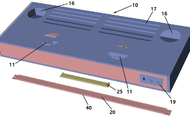
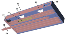
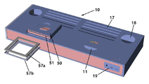
도 1은 본 발명에 따른 배기 장치에서 분리판과 보강편이 분리된 것을 상방에서 바라본 사시도이고, 도 2는 본 발명에 따른 배기 장치에서 분리판과 보강편이 분리된 것을 하방에서 바라본 사시도이며, 도 3은 본 발명에 따른 분리판과 보강편을 나타낸 사시도이다.FIG. 1 is a perspective view of a separating plate and a reinforcing piece separated from an upper part of an exhausting apparatus according to the present invention, FIG. 2 is a perspective view of a separating plate and a reinforcing piece separated from the lower part of the exhausting apparatus according to the present invention, Is a perspective view showing a separator plate and a reinforcing piece according to the present invention.
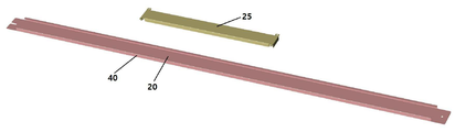
본 발명에 따른 배기 장치는, 상면에 적어도 하나의 흡입공(11)이 형성되는 후드 몸체(10); 후드 몸체(10)의 하부에 양측 단부가 볼트로 체결되어 개별적으로 분리 가능한 다수의 분리판(20); 분리판(20)이 서로 이격되어서 형성되고, 실내의 오염된 공기를 흡입하는 흡입구(30); 및 분리판(20)의 전단 또는 후단에 형성되고, 흡입구(30)를 통하여 흡입되는 오염된 공기를 안내하는 날개편(40);을 포함한다.An exhaust device according to the present invention comprises: a hood body (10) having at least one suction hole (11) formed on an upper surface thereof; A plurality of separating
후드 몸체(10)의 상면에는 적어도 하나의 흡입공(11)이 형성되고, 주방이 커지면 흡입공(11)의 개수도 늘어난다. 후드 몸체(10)의 하부에는 다수의 분리판(20)이 결합되는데, 분리판(20)의 양측 단부가 볼트로 체결되므로 다수의 분리판(20)은 개별적으로 분해 조립이 가능하며, 더 편리한 분해 조립을 위하여 분리판(20)의 좌측 단부에 형성되는 볼트공을 좌측 끝단까지 틔울 수 있다.At least one
이때, 분리판(20)은 소정 간격으로 서로 떨어져 후드 몸체(10)의 하부에 결합되므로 분리판(20)의 이격된 공간이 흡입구(30)가 되고, 흡입구(30)로 음식물이 조리될 때 발생하는 냄새, 연기 또는 유증기 등의 오염된 실내 공기가 흡입된다.At this time, since the
분리판(20)의 전단 및/또는 후단에 형성되는 날개편(40)은 흡입구(30)를 통하여 흡입되는 오염된 실내 공기를 안내하므로 본 발명에 따른 배기 장치는 더욱 효과적으로 오염된 실내 공기를 흡입하여 배출할 수 있다.Since the
또한, 분리판(20)의 길이가 길어지는 경우에 분리판(20)의 강도를 보강하기 위하여 분리판(20)의 상부에 보강편(25)을 볼트로 결합할 수 있다.In addition, when the length of the
도 4는 후드 몸체에서 상면이 개방된 것을 나타내는 사시도이다.4 is a perspective view showing that the upper surface of the hood body is opened.
후드 몸체(10)의 내부에 분할판(15)이 형성되어 후드 몸체(10)를 전방부와 후방부로 양분하고, 분할판(15)은 후방으로 경사지게 형성된다. 이때, 후드 몸체(10)의 전방부 상면에는 흡입공(11)이 형성되고, 후드 몸체(10)의 후방부 상면에는 적어도 하나의 공급공(16)이 형성되며, 후드 몸체(10)의 후방부 상면에는 상기 공급공(16)으로부터 공급되는 신선한 실외 공기를 실내로 공급하는 적어도 하나의 급기구(17)가 형성된다.A
또한, 분할판(15)은 후드 몸체(10)의 내부에서 좌측 또는 우측 하방으로 경사지거나 전방으로 경사지게 형성될 수 있고, 분할판(15)이 후드 몸체(10)의 내부를 나누는 형상에 따라 흡입공(11), 공급공(16) 및 급기구(17)의 형성 위치가 결정된다.The
도 1에서는 후드 몸체(10)의 후방부 상면의 좌측 및 우측에 2개의 공급공(16)이 형성되어 있으나, 주방이 크지 않으면 본 발명에 따른 배기 장치가 가깝게 위치하는 벽면 쪽의 공급공(16) 하나로도 충분하다. 즉, 본 발명에 따른 배기 장치가 좌측 벽에 가깝게 위치하면, 후드 몸체(10)의 후방부 상면의 좌측에 공급공(16)을 개방하고, 우측의 공급공(16)을 폐쇄할 수 있다.In FIG. 1, two
공급공(16)에는 급기 덕트(미도시)가 연결되고, 상기 급기 덕트의 끝단에는 송풍팬(미도시)이 형성된다.An air supply duct (not shown) is connected to the
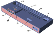
도 5는 후드 몸체의 흡입구에 필터 케이스가 설치된 것을 상방에서 바라본 사시도이고, 도 6은 후드 몸체의 흡입구에 필터 케이스가 설치된 것을 하방에서 바라본 사시도이며, 도 7은 필터 케이스에서 필터 프레임이 분리된 것을 나타내는 사시도이다.FIG. 6 is a perspective view of a filter case installed in a suction port of the hood body from below, and FIG. 7 is a perspective view of a filter case in which a filter frame is separated from the filter case FIG.
흡입공(11)의 상부에 필터 케이스(50)가 형성되고, 필터 케이스(50)의 전면에 삽입구(51)가 형성되며, 삽입구(51)에 필터(미도시)가 삽입된다. 이때, 필터는 필터 프레임(57)에 결합되어 삽입구(51)에 삽입될 수 있고, 필터 프레임(57)은 상부 프레임(57a) 및/또는 하부 프레임(57b)을 포함할 수 있으며, 상부 프레임(57a)의 하부, 하부 프레임(57b)의 상부, 또는 상부 프레임(57a)과 하부 프레임(57b)의 사이에 필터가 끼워질 수 있다. 이때, 상부 프레임(57a)과 하부 프레임(57b)의 사이에 위치하는 필터는 상하 2개가 배치되고, 2개의 필터 사이에 링을 삽입하여 상하로 위치하는 필터를 소정 간격으로 이격시킬 수 있으며, 이격된 2개의 필터는 훨씬 우수한 필터링 효과를 나타낸다. 이와 같이 필터를 서랍식으로 분해 조립할 수 있으므로 필터의 청소와 교체가 아주 편리하다.A
하부 몸체(10)의 하면에는 조명등(미도시)이 설치될 수 있는 적어도 하나의 조명공(12)이 형성되고, 하부 몸체(10)의 전면 우측에는 조명등, 송풍팬(미도시) 및 배기팬(미도시)의 작동 스위치(19)가 형성된다.At least one
도 8은 본 발명에 따른 배기 장치에서 필터 케이스의 상부에 기름 제거 덕트가 설치되고 개폐판이 개방된 것을 상방에서 바라본 사시도이고, 도 9는 본 발명에 따른 배기 장치에서 필터 케이스의 상부에 기름 제거 덕트가 설치되고 개폐판이 개방된 것을 하방에서 바라본 사시도이다.FIG. 8 is a perspective view of an exhaust device according to the present invention, in which an oil removing duct is installed at an upper portion of a filter case and an opening / closing plate is opened. FIG. 9 is a cross- And the open / close plate is opened. Fig.
흡입공(11) 또는 필터 케이스(50)의 상부에 기름 제거 덕트(60)가 수평으로 연결되고, 기름 제거 덕트(60)의 전면에는 개폐판(61)이 형성된다. 기름 제거 덕트(60)의 벽면에 기름때가 많이 끼면, 개폐판(61)을 개방하고, 기름 제거 덕트(60)의 벽면을 깨끗하게 청소할 수 있다.An
또한, 기름 제거 덕트(60)의 좌측면과 우측면에 덕트공(62)이 형성되어 있으나, 본 발명에 따른 배기 장치가 가깝게 위치하는 벽면 쪽의 덕트공(62)이 사용된다. 즉, 본 발명에 따른 배기 장치가 좌측 벽에 가깝게 위치하면, 기름 제거 덕트(60)의 좌측면의 덕트공(62)을 개방하고, 우측면의 덕트공(62)을 폐쇄한다.A
덕트공(62)에는 배기 덕트(미도시)가 연결되고, 상기 배기 덕트의 끝단에는 배기팬(미도시)이 형성된다.An exhaust duct (not shown) is connected to the
본 발명에 따른 배기 장치의 작동 과정을 설명하면, 다음과 같다.The operation of the exhaust system according to the present invention will now be described.
배기팬(미도시)이 작동하면, 음식물이 조리될 때 발생하는 냄새, 연기 또는 유증기 등의 오염된 실내 공기는 분리판(20) 사이의 흡입구(30)로 유입되고, 분리판(20)의 날개편(40)이 오염된 실내 공기를 안내하므로 훨씬 효과적으로 오염된 실내 공기를 흡입할 수 있다. 흡입구(30)로 흡입된 실내 공기는 후드 몸체(10)의 전방부와 흡입공(11)을 통과하고, 필터를 거치면서 기름때 등이 상당히 걸러진다. 필터에 의해 걸러지지 않은 기름때 등은 수평으로 연결되는 기름 제거 덕트(60)에서 유동의 방향이 수직으로 바뀌면서 나머지 기름때 등은 기름 제거 덕트(60)의 벽면에 쌓인다.When the exhaust fan (not shown) is operated, contaminated indoor air such as odor, smoke, or vapor generated when the food is cooked is introduced into the
오랜 사용으로 본 발명에 따른 배기 장치를 청소하여야 하는 경우에 사용자는 분리판(20)을 개별적으로 분리하여 후드 몸체(10)의 내부를 간편하게 청소할 수 있으며, 필터 케이스(50)에서 필터를 제거한 후 손쉽게 필터를 세척하고 필터를 삽입할 수 있고, 기름 제거 덕트(60)에서 개폐판(61)을 개방한 후 기름 제거 덕트(60)의 벽면을 용이하게 청소할 수 있다.When the exhaust system according to the present invention is to be cleaned for a long time, the user can separate the
송풍팬(미도시)이 작동하면, 신선한 실외 공기가 공급공(16)으로 공급되고, 후드 몸체(10)의 후방부를 거쳐 급기구(17)를 통하여 실내의 천장으로 공급되며, 급기구(17)를 통해 공급된 실외 공기는 천장을 타고 배기 장치의 전방으로 유동하면서 실내에 큰 와류(vortex)를 형성하므로, 상기 와류는 음식물이 조리될 때 발생하는 냄새, 연기 또는 유증기 등의 오염된 실내 공기가 흡입구(30)로 더욱 효과적으로 흡입되도록 돕는다.Fresh outside air is supplied to the
이상의 설명은 본 발명의 기술사상을 예시적으로 설명한 것에 불과한 것으로 본 발명이 속하는 기술분야에서 통상의 지식을 가진 자라면 본 발명의 본질적인 특성에서 벗어나지 않는 범위에서 다양한 수정 및 변형이 가능할 것이다. 따라서 본 발명에 개시된 실시예는 본 발명의 기술사상을 한정하기 위한 것이 아니라 설명하기 위한 것이고, 이러한 실시예에 의하여 본 발명의 기술사상의 범위가 한정되는 것은 아니다. 본 발명의 보호범위는 아래의 특허청구범위에 의하여 해석되어야 하며, 그와 동등한 범위 내에 있는 모든 기술사상은 본 발명의 권리범위에 포함되는 것으로 해석되어야 할 것이다.The above description is merely illustrative of the technical idea of the present invention, and various modifications and changes may be made without departing from the essential characteristics of the present invention by those skilled in the art to which the present invention belongs. Therefore, the embodiments disclosed in the present invention are not intended to limit the scope of the present invention but to limit the scope of the technical idea of the present invention. The scope of protection of the present invention should be construed according to the following claims, and all technical ideas within the scope of the claims should be construed as being included in the scope of the present invention.
10: 후드 몸체 11: 흡입공
12: 조명공 15: 분할판
16: 공급공 17: 급기구
19: 작동 스위치 20: 분리판
25: 보강편 30: 흡입구
40: 날개편 50: 필터 케이스
51: 삽입구 57: 필터 프레임
60: 기름 제거 덕트 61: 개폐판
62: 덕트공10: hood body 11: suction hole
12: Lighting ball 15: Partition plate
16: supply hole 17:
19: Operation switch 20: Split plate
25: reinforcement piece 30: inlet
40: Day reorganization 50: Filter case
51: insertion port 57: filter frame
60: Oil removing duct 61: Opening and closing plate
62: Duct ball
Claims (5)
상기 후드 몸체(10)의 하부에 양측 단부가 볼트로 체결되어 개별적으로 분리 가능한 다수의 분리판(20);
상기 분리판(20)이 서로 이격되어서 형성되고, 실내의 오염된 공기를 흡입하는 흡입구(30); 및
상기 분리판(20)의 전단 또는 후단에 형성되고, 상기 흡입구(30)를 통하여 흡입되는 오염된 공기를 안내하는 날개편(40);을 포함하는 것을 특징으로 하는 배기 후드.
A hood body (10) having at least one suction hole (11) formed on an upper surface thereof;
A plurality of separating plates 20 which are fastened to the lower portion of the hood body 10 by bolts at both side ends thereof and can be individually separated;
A suction port 30 formed by separating the separating plates 20 from each other and sucking contaminated air in the room; And
And a blade piece (40) formed at a front end or a rear end of the separator plate (20) and guiding contaminated air sucked through the suction port (30).
상기 후드 몸체(10)를 전방부와 후방부로 양분하는 분할판(15)이 형성되고, 상기 분할판(15)은 후방으로 경사지게 형성되며, 상기 흡입공(11)은 상기 후드 몸체(10)의 전방부 상면에 형성되고, 상기 후드 몸체(10)의 후방부 상면에 적어도 하나의 공급공(16)이 형성되며, 상기 후드 몸체(10)의 후방부 상면에 상기 공급공(16)으로부터 공급되는 실외 공기를 실내로 공급하는 적어도 하나의 급기구(17)가 형성되는 것을 특징으로 하는 배기 후드.
The method according to claim 1,
A partition plate 15 for dividing the hood body 10 into a front part and a rear part is formed and the partition plate 15 is inclined rearwardly and the suction hole 11 is formed in the rear part of the hood body 10 At least one supply hole 16 is formed on the upper surface of the rear portion of the hood body 10 and a supply hole 16 is formed in the upper surface of the rear portion of the hood body 10 Wherein at least one air supply mechanism (17) for supplying outdoor air to the room is formed.
상기 흡입공(11)의 상부에 필터 케이스(50)가 형성되고, 상기 필터 케이스(50)의 전면에 삽입구(51)가 형성되며, 상기 삽입구(51)에 필터가 삽입되는 것을 특징으로 하는 배기 후드.
3. The method according to claim 1 or 2,
A filter case 50 is formed on the upper portion of the suction hole 11 and an insertion port 51 is formed on the front surface of the filter case 50 so that a filter is inserted into the insertion hole 51. [ Hood.
상기 필터는 필터 프레임(57)에 결합되어 상기 삽입구(51)에 삽입되는 것을 특징으로 하는 배기 후드.
The method of claim 3,
Wherein the filter is coupled to the filter frame (57) and inserted into the insertion port (51).
상기 흡입공(11)의 상부에 기름 제거 덕트(60)가 수평으로 연결되고, 상기 기름 제거 덕트(60)의 전면에는 개폐판(61)이 형성되는 것을 특징으로 하는 배기 후드.3. The method according to claim 1 or 2,
Wherein an oil removal duct (60) is horizontally connected to an upper portion of the suction hole (11), and an opening / closing plate (61) is formed on a front surface of the oil removal duct (60).
Priority Applications (1)
| Application Number | Priority Date | Filing Date | Title |
|---|---|---|---|
| KR1020160068886A KR20170136841A (en) | 2016-06-02 | 2016-06-02 | A ventilation hood |
Applications Claiming Priority (1)
| Application Number | Priority Date | Filing Date | Title |
|---|---|---|---|
| KR1020160068886A KR20170136841A (en) | 2016-06-02 | 2016-06-02 | A ventilation hood |
Publications (1)
| Publication Number | Publication Date |
|---|---|
| KR20170136841A true KR20170136841A (en) | 2017-12-12 |
Family
ID=60944018
Family Applications (1)
| Application Number | Title | Priority Date | Filing Date |
|---|---|---|---|
| KR1020160068886A KR20170136841A (en) | 2016-06-02 | 2016-06-02 | A ventilation hood |
Country Status (1)
| Country | Link |
|---|---|
| KR (1) | KR20170136841A (en) |
-
2016
- 2016-06-02 KR KR1020160068886A patent/KR20170136841A/en active Search and Examination
Similar Documents
| Publication | Publication Date | Title |
|---|---|---|
| US9835339B2 (en) | Induction ventilation system for air supply and exhaust | |
| KR101614105B1 (en) | Direct fire roaster having function air purification and circulation | |
| CN1332153C (en) | Multifunctional oven over range | |
| CN111012161B (en) | Electric cooking appliance | |
| JP4451359B2 (en) | Cooking table | |
| JP6790247B2 (en) | Ventilation device with air intake | |
| US20230280045A1 (en) | Combination appliance | |
| CN107940533A (en) | A kind of embedded integration stove | |
| KR20190107385A (en) | The electric precipitation hood | |
| KR20110012038U (en) | Apparatus for rangehood having subsidiary inhale hole in kitchen | |
| KR20170136841A (en) | A ventilation hood | |
| JP5070080B2 (en) | Exhaust system | |
| KR101900036B1 (en) | A dust collector having a spiral oil collecting part and an oil melting part | |
| CN207741166U (en) | A kind of embedded integration stove | |
| KR100577097B1 (en) | A kitchen hood of charging and discharging air | |
| CN218295832U (en) | Integrated kitchen with ground air drying function | |
| CN109915970A (en) | A kind of integrated fresh air purifying unit of kitchen furred ceiling | |
| CN217852514U (en) | Smokeless baking tray | |
| CN211781311U (en) | Oil-removing and odor-removing environment-friendly kitchen range smoke exhausting equipment | |
| KR102624361B1 (en) | Recirculation ventilation system | |
| KR200214878Y1 (en) | An air circulation type of roaster | |
| EP4008966A1 (en) | Combination appliance | |
| CN107435960A (en) | kitchen air purifying system | |
| CN111780181A (en) | Smoke exhaust ventilator | |
| KR200246461Y1 (en) | Island Stand style Range Hood |
Legal Events
| Date | Code | Title | Description |
|---|---|---|---|
| A201 | Request for examination | ||
| E902 | Notification of reason for refusal | ||
| AMND | Amendment | ||
| E902 | Notification of reason for refusal | ||
| AMND | Amendment | ||
| E601 | Decision to refuse application | ||
| AMND | Amendment | ||
| J201 | Request for trial against refusal decision | ||
| J121 | Written withdrawal of request for trial |