KR20170133392A - Injection molding method of thermosetting resin composition - Google Patents
Injection molding method of thermosetting resin composition Download PDFInfo
- Publication number
- KR20170133392A KR20170133392A KR1020177030217A KR20177030217A KR20170133392A KR 20170133392 A KR20170133392 A KR 20170133392A KR 1020177030217 A KR1020177030217 A KR 1020177030217A KR 20177030217 A KR20177030217 A KR 20177030217A KR 20170133392 A KR20170133392 A KR 20170133392A
- Authority
- KR
- South Korea
- Prior art keywords
- resin composition
- thermosetting resin
- temperature
- injection molding
- mold
- Prior art date
Links
Images

Classifications
-
- B—PERFORMING OPERATIONS; TRANSPORTING
- B29—WORKING OF PLASTICS; WORKING OF SUBSTANCES IN A PLASTIC STATE IN GENERAL
- B29C—SHAPING OR JOINING OF PLASTICS; SHAPING OF MATERIAL IN A PLASTIC STATE, NOT OTHERWISE PROVIDED FOR; AFTER-TREATMENT OF THE SHAPED PRODUCTS, e.g. REPAIRING
- B29C45/00—Injection moulding, i.e. forcing the required volume of moulding material through a nozzle into a closed mould; Apparatus therefor
- B29C45/0001—Injection moulding, i.e. forcing the required volume of moulding material through a nozzle into a closed mould; Apparatus therefor characterised by the choice of material
-
- B—PERFORMING OPERATIONS; TRANSPORTING
- B29—WORKING OF PLASTICS; WORKING OF SUBSTANCES IN A PLASTIC STATE IN GENERAL
- B29C—SHAPING OR JOINING OF PLASTICS; SHAPING OF MATERIAL IN A PLASTIC STATE, NOT OTHERWISE PROVIDED FOR; AFTER-TREATMENT OF THE SHAPED PRODUCTS, e.g. REPAIRING
- B29C45/00—Injection moulding, i.e. forcing the required volume of moulding material through a nozzle into a closed mould; Apparatus therefor
- B29C45/17—Component parts, details or accessories; Auxiliary operations
- B29C45/72—Heating or cooling
- B29C45/7207—Heating or cooling of the moulded articles
-
- B—PERFORMING OPERATIONS; TRANSPORTING
- B29—WORKING OF PLASTICS; WORKING OF SUBSTANCES IN A PLASTIC STATE IN GENERAL
- B29C—SHAPING OR JOINING OF PLASTICS; SHAPING OF MATERIAL IN A PLASTIC STATE, NOT OTHERWISE PROVIDED FOR; AFTER-TREATMENT OF THE SHAPED PRODUCTS, e.g. REPAIRING
- B29C45/00—Injection moulding, i.e. forcing the required volume of moulding material through a nozzle into a closed mould; Apparatus therefor
- B29C45/17—Component parts, details or accessories; Auxiliary operations
- B29C45/76—Measuring, controlling or regulating
- B29C45/78—Measuring, controlling or regulating of temperature
-
- C—CHEMISTRY; METALLURGY
- C08—ORGANIC MACROMOLECULAR COMPOUNDS; THEIR PREPARATION OR CHEMICAL WORKING-UP; COMPOSITIONS BASED THEREON
- C08K—Use of inorganic or non-macromolecular organic substances as compounding ingredients
- C08K3/00—Use of inorganic substances as compounding ingredients
- C08K3/34—Silicon-containing compounds
- C08K3/36—Silica
-
- B—PERFORMING OPERATIONS; TRANSPORTING
- B29—WORKING OF PLASTICS; WORKING OF SUBSTANCES IN A PLASTIC STATE IN GENERAL
- B29C—SHAPING OR JOINING OF PLASTICS; SHAPING OF MATERIAL IN A PLASTIC STATE, NOT OTHERWISE PROVIDED FOR; AFTER-TREATMENT OF THE SHAPED PRODUCTS, e.g. REPAIRING
- B29C45/00—Injection moulding, i.e. forcing the required volume of moulding material through a nozzle into a closed mould; Apparatus therefor
- B29C45/0053—Injection moulding, i.e. forcing the required volume of moulding material through a nozzle into a closed mould; Apparatus therefor combined with a final operation, e.g. shaping
- B29C45/0055—Shaping
- B29C2045/0058—Shaping removing material
-
- B—PERFORMING OPERATIONS; TRANSPORTING
- B29—WORKING OF PLASTICS; WORKING OF SUBSTANCES IN A PLASTIC STATE IN GENERAL
- B29C—SHAPING OR JOINING OF PLASTICS; SHAPING OF MATERIAL IN A PLASTIC STATE, NOT OTHERWISE PROVIDED FOR; AFTER-TREATMENT OF THE SHAPED PRODUCTS, e.g. REPAIRING
- B29C45/00—Injection moulding, i.e. forcing the required volume of moulding material through a nozzle into a closed mould; Apparatus therefor
- B29C45/17—Component parts, details or accessories; Auxiliary operations
- B29C45/18—Feeding the material into the injection moulding apparatus, i.e. feeding the non-plastified material into the injection unit
- B29C45/1816—Feeding auxiliary material, e.g. colouring material
- B29C2045/1833—Feeding auxiliary material, e.g. colouring material recycling sprues or runners
-
- B—PERFORMING OPERATIONS; TRANSPORTING
- B29—WORKING OF PLASTICS; WORKING OF SUBSTANCES IN A PLASTIC STATE IN GENERAL
- B29C—SHAPING OR JOINING OF PLASTICS; SHAPING OF MATERIAL IN A PLASTIC STATE, NOT OTHERWISE PROVIDED FOR; AFTER-TREATMENT OF THE SHAPED PRODUCTS, e.g. REPAIRING
- B29C2793/00—Shaping techniques involving a cutting or machining operation
- B29C2793/009—Shaping techniques involving a cutting or machining operation after shaping
-
- B—PERFORMING OPERATIONS; TRANSPORTING
- B29—WORKING OF PLASTICS; WORKING OF SUBSTANCES IN A PLASTIC STATE IN GENERAL
- B29K—INDEXING SCHEME ASSOCIATED WITH SUBCLASSES B29B, B29C OR B29D, RELATING TO MOULDING MATERIALS OR TO MATERIALS FOR MOULDS, REINFORCEMENTS, FILLERS OR PREFORMED PARTS, e.g. INSERTS
- B29K2101/00—Use of unspecified macromolecular compounds as moulding material
- B29K2101/10—Thermosetting resins
-
- C—CHEMISTRY; METALLURGY
- C08—ORGANIC MACROMOLECULAR COMPOUNDS; THEIR PREPARATION OR CHEMICAL WORKING-UP; COMPOSITIONS BASED THEREON
- C08K—Use of inorganic or non-macromolecular organic substances as compounding ingredients
- C08K3/00—Use of inorganic substances as compounding ingredients
- C08K3/18—Oxygen-containing compounds, e.g. metal carbonyls
- C08K3/20—Oxides; Hydroxides
- C08K3/22—Oxides; Hydroxides of metals
- C08K2003/2227—Oxides; Hydroxides of metals of aluminium
-
- C—CHEMISTRY; METALLURGY
- C08—ORGANIC MACROMOLECULAR COMPOUNDS; THEIR PREPARATION OR CHEMICAL WORKING-UP; COMPOSITIONS BASED THEREON
- C08K—Use of inorganic or non-macromolecular organic substances as compounding ingredients
- C08K3/00—Use of inorganic substances as compounding ingredients
- C08K3/18—Oxygen-containing compounds, e.g. metal carbonyls
- C08K3/20—Oxides; Hydroxides
- C08K3/22—Oxides; Hydroxides of metals
- C08K2003/2237—Oxides; Hydroxides of metals of titanium
-
- C—CHEMISTRY; METALLURGY
- C08—ORGANIC MACROMOLECULAR COMPOUNDS; THEIR PREPARATION OR CHEMICAL WORKING-UP; COMPOSITIONS BASED THEREON
- C08K—Use of inorganic or non-macromolecular organic substances as compounding ingredients
- C08K3/00—Use of inorganic substances as compounding ingredients
- C08K3/18—Oxygen-containing compounds, e.g. metal carbonyls
- C08K3/24—Acids; Salts thereof
- C08K3/26—Carbonates; Bicarbonates
- C08K2003/265—Calcium, strontium or barium carbonate
-
- C—CHEMISTRY; METALLURGY
- C08—ORGANIC MACROMOLECULAR COMPOUNDS; THEIR PREPARATION OR CHEMICAL WORKING-UP; COMPOSITIONS BASED THEREON
- C08K—Use of inorganic or non-macromolecular organic substances as compounding ingredients
- C08K2201/00—Specific properties of additives
- C08K2201/01—Magnetic additives
-
- C—CHEMISTRY; METALLURGY
- C08—ORGANIC MACROMOLECULAR COMPOUNDS; THEIR PREPARATION OR CHEMICAL WORKING-UP; COMPOSITIONS BASED THEREON
- C08K—Use of inorganic or non-macromolecular organic substances as compounding ingredients
- C08K3/00—Use of inorganic substances as compounding ingredients
- C08K3/01—Use of inorganic substances as compounding ingredients characterized by their specific function
- C08K3/013—Fillers, pigments or reinforcing additives
-
- C—CHEMISTRY; METALLURGY
- C08—ORGANIC MACROMOLECULAR COMPOUNDS; THEIR PREPARATION OR CHEMICAL WORKING-UP; COMPOSITIONS BASED THEREON
- C08K—Use of inorganic or non-macromolecular organic substances as compounding ingredients
- C08K3/00—Use of inorganic substances as compounding ingredients
- C08K3/40—Glass
Abstract
[과제] 본 발명은 열경화성 수지 조성물을 연속적으로 사출성형할 수 있고, 성형시 발생하는 불필요한 부분을 재사용할 수 있는 방법을 제공한다.
[해결방법] 먼저, 열경화성 수지 조성물을 경화 반응이 완료되지 않은 상태에서 금형으로 사출한다. 이어서, 열경화성 수지 조성물을 금형 내에서 반경화 상태가 될 때까지 냉각한다. 이어서, 열경화성 수지 조성물을 반경화물 상태에서 금형으로부터 분리한다. 그 후, 열경화성 수지 조성물을, 제품이 되는 부분과 불필요한 부분으로 나눈다. 이어서. 제품이 되는 부분을 별도로 가열하고, 열경화성 수지 조성물의 열경화 반응을 진행시킨다. 불필요한 부분은, 재생 원료로서 이용된다. 바람직한 양태에서는, 먼저, 불필요한 부분을 분쇄한다. 이어서, 이 분쇄물을 신품의 열경화성 수지 조성물과 혼합한다. 그리고, 이 혼합물을 이용해 새롭게 사출성형을 실시한다.[PROBLEMS] To provide a method capable of continuous injection molding of a thermosetting resin composition and reusing an unnecessary portion generated during molding.
[Solution] First, the thermosetting resin composition is injected into a mold without completion of the curing reaction. Subsequently, the thermosetting resin composition is cooled in the mold until it becomes semi-hardened. Subsequently, the thermosetting resin composition is separated from the mold in a semi-hardened state. Thereafter, the thermosetting resin composition is divided into a product portion and an unnecessary portion. next. The part to be a product is heated separately to advance the thermosetting reaction of the thermosetting resin composition. An unnecessary portion is used as a raw material for regeneration. In a preferred embodiment, first, an unnecessary portion is crushed. Subsequently, this pulverized product is mixed with a new thermosetting resin composition. Then, injection molding is newly performed using this mixture.
Description
본 발명은, 열경화성 수지 조성물의 사출성형 방법에 관한 것이다.The present invention relates to an injection molding method of a thermosetting resin composition.
열가소성 수지의 사출성형은 통상 연속적으로 이루어지며 생산성이 높은 제법으로 알려져 있다. 그러나, 열가소성 수지용 사출성형기를 사용하여, 열경화성 수지의 사출을 계속하면, 금형 주변 부재를 포함하는 사출성형기 전체의 온도가 상승하고, 수지의 경화 개시 온도를 상회하여 수지가 경화하기 때문에, 연속적으로 성형을 실시하는 것은 곤란하다.Injection molding of a thermoplastic resin is usually carried out continuously and is known as a high productivity method. However, if the injection molding of the thermosetting resin is continued by using the injection molding machine for thermoplastic resin, the temperature of the entire injection molding machine including the peripheral members of the mold increases and the resin hardens due to the temperature exceeding the curing start temperature of the resin. It is difficult to perform molding.
또한, 사출성형을 실시해서 성형품이 분리된 경우에는, 제품이 되지 않는 불필요한 부분 (이른바, 스풀 러너 (Spool runner))가 발생한다. 이 불필요한 부분은, 금형 내에서 수지 조성물의 주입구부터 제품의 형태 사이의 유로 (流路)에서 굳어진 수지 조성물에 유래한다. 수지 조성물이 열가소성 수지 조성물인 경우, 성형 후, 이 불필요한 부분을 성형품에서 분리하여, 새로운 열가소성 수지 조성물과 혼합함으로써, 재사용을 도모할 수 있다.In addition, when the molded product is separated by injection molding, an unnecessary portion (so-called spool runner) which does not become a product is generated. This unnecessary portion is derived from the resin composition hardened in the flow path between the injection port of the resin composition and the form of the product in the mold. When the resin composition is a thermoplastic resin composition, after the molding, the unnecessary portion is separated from the molded article and mixed with the new thermoplastic resin composition, whereby reuse can be achieved.
한편, 수지 조성물이 열경화성 수지 조성물인 경우, 성형시에 수지 조성물이 경화하기 때문에, 불필요한 부분은 재사용되지 않고 폐기된다. 그러나, 불필요한 부분의 수지 조성물을 그대로 폐기해버리는 것은 아깝다. 또한, 제품이 소형인 경우, 불필요한 부분이 상대적으로 크게 된다. 이 때문에, 수지에 고액의 필러를 배합하는 경우에는, 결과적으로 다량의 필러가 폐기되는 형태가 되고 만다. 그리고, 이것이, 일부 소형 제품의 제조 비용을 끌어올리는 원인이 되고 있다.On the other hand, when the resin composition is a thermosetting resin composition, since the resin composition hardens at the time of molding, unnecessary parts are discarded without being reused. However, it is a waste to discard an unnecessary portion of the resin composition as it is. Further, when the product is small, the unnecessary portion becomes relatively large. For this reason, when a high-pliability filler is added to a resin, a large amount of filler is consequently discarded as a result. And this causes the manufacturing cost of some small-sized products to increase.
이에, 본 발명은 열경화성 수지 조성물을 연속적으로 사출성형할 수 있고, 성형시에 생기는 불필요한 부분을 재사용할 수 있는 방법을 제공하는 것을 목적으로 한다.Accordingly, it is an object of the present invention to provide a method capable of continuous injection molding of a thermosetting resin composition, and reusing an unnecessary portion generated at the time of molding.
본 발명의 일 양태에서는, 먼저, 열경화성 수지 조성물을 경화 반응이 완료되지 않은 상태에서 금형으로 사출한다. 이어서, 열경화성 수지 조성물을 금형 내에서 반경화 상태가 될 때까지 냉각한다. 이어서, 열경화성 수지 조성물을 반경화 상태에서 금형으로부터 분리한다. 이어서, 열경화성 수지 조성물을 제품이 되는 부분과 불필요한 부분으로 나눈다. 이어서, 제품이 되는 부분을 별도로 가열하고, 열경화성 수지의 열경화 반응을 진행시킨다. 불필요한 부분은 새로운 사출성형의 원료로서 이용된다. 바람직한 양태에서는, 먼저, 불필요한 부분을 분쇄한다. 이어서, 이 분쇄물을 새로운 열경화성 수지 조성물과 혼합한다. 그리고, 이 혼합물을 사용하여, 새로운 사출성형을 실시한다.In one embodiment of the present invention, first, the thermosetting resin composition is injected into a mold without completion of the curing reaction. Subsequently, the thermosetting resin composition is cooled in the mold until it becomes semi-hardened. Subsequently, the thermosetting resin composition is separated from the mold in a semi-cured state. Subsequently, the thermosetting resin composition is divided into a product portion and an unnecessary portion. Subsequently, the part to be a product is heated separately to advance the thermosetting reaction of the thermosetting resin. Unnecessary parts are used as raw materials for new injection molding. In a preferred embodiment, first, an unnecessary portion is crushed. Then, the pulverized material is mixed with the new thermosetting resin composition. Then, using this mixture, a new injection molding is carried out.
본 발명에 의하면, 열경화성 수지 조성물을 연속적으로 사출성형할 수 있고, 성형시에 생기는 불필요한 부분을 재사용할 수 있다. 이로 인해, 열경화성 수지 조성물의 제조 비용을 절감할 수 있다. According to the present invention, the thermosetting resin composition can be injection-molded continuously, and an unnecessary portion generated at the time of molding can be reused. As a result, the manufacturing cost of the thermosetting resin composition can be reduced.
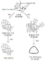
도 1은 본 실시형태의 열경화성 수지 조성물의 사출성형 방법을 설명하기 위한 모식도이다.
도 2는 본 실시형태의 열경화성 수지 조성물의 사출성형 방법을 설명하는 공정도이다.
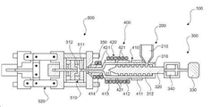
도 3은 본 실시형태의 열경화성 수지 조성물의 사출성형 방법에 사용되는 사출성형기의 실시형태를 나타내는 단면 모식도이다.
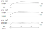
도 4는 각종 사출성형기에서 실린더의 온도 제어를 실시한 경우의, 수지 조성물의 온도 변화를 나타내는 그래프이다.1 is a schematic view for explaining an injection molding method of the thermosetting resin composition of the present embodiment.
Fig. 2 is a process diagram for explaining the injection molding method of the thermosetting resin composition of the present embodiment.
3 is a schematic cross-sectional view showing an embodiment of an injection molding machine used in an injection molding method of the thermosetting resin composition of the present embodiment.
Fig. 4 is a graph showing the temperature change of the resin composition when the temperature of the cylinder is controlled in various injection molding machines.
열경화성 수지 조성물의 사출성형 방법Injection molding method of thermosetting resin composition
도 2는, 본 실시형태의 열경화성 수지 조성물의 사출성형 방법의 각 공정을 나타내는 공정도이다. 도 2에 나타낸 바와 같이, 본 실시형태의 열경화성 수지 조성물의 사출성형 방법은 하기의 공정으로 구성된다.Fig. 2 is a process diagram showing each step of the injection molding method of the thermosetting resin composition of the present embodiment. As shown in Fig. 2, the injection molding method of the thermosetting resin composition of the present embodiment comprises the following steps.
공정 1 - 열경화성 수지 조성물의 공급 : 원료가 되는 열경화성 수지 조성물을 사출성형기의 실린더에 공급한다.Step 1 - Supply of the thermosetting resin composition: The thermosetting resin composition to be the raw material is supplied to the cylinder of the injection molding machine.
공정 2 - 열경화성 수지 조성물의 연화 : 열경화성 수지 조성물을 실린더 내에서 연화 또는 용융시킨다.Step 2 - Softening of the thermosetting resin composition: The thermosetting resin composition is softened or melted in a cylinder.
공정 3 - 열경화성 수지 조성물의 사출 : 열경화성 수지 조성물을 실린더에서 금형으로 사출한다.Step 3 - Injection of thermosetting resin composition: The thermosetting resin composition is injected from a cylinder into a mold.
공정 4 - 열경화성 수지 조성물의 반경화 : 금형 내에서 열경화성 수지 조성물을 냉각하여 반경화시켜, B 단계 상태로 한다.Step 4 - Semi-hardening of the thermosetting resin composition: The thermosetting resin composition is cooled in the mold and semi-cured to obtain a B-step state.
공정 5 - 성형품의 분리 : 금형에서 성형된 열경화성 수지 조성물을 분리한다.Step 5 - Separation of molded article: The molded thermosetting resin composition is separated from the mold.
공정 6 - 제품이 되는 부분과 불필요한 부분의 분리 : 성형된 열경화성 수지 조성물을, 제품이 되는 부분과 불필요한 부분으로 나눈다.Step 6 - Separation of a product part and an unnecessary part: The molded thermosetting resin composition is divided into a product part and an unnecessary part.
공정 7 - 가열 : 제품이 되는 부분을 가열하고 열경화성 수지 조성물의 열경화 반응을 진행시킨다. 이에 의해, 제품을 얻을 수 있다.Step 7 - Heating: The part to be a product is heated to advance the thermosetting reaction of the thermosetting resin composition. Thereby, a product can be obtained.
공정 8 - 분쇄 : 불필요한 부분은 잘게 분쇄된다. 그리고, 얻어진 분쇄물은 새로운 열경화성 수지 조성물과 혼합되고, 이 혼합물은 새롭게 사출성형에 제공된다.Step 8 - Grinding: Unnecessary parts are finely ground. Then, the obtained pulverized product is mixed with the new thermosetting resin composition, and this mixture is newly provided for injection molding.
도 3 및 도 1에 근거하여, 본 실시형태의 사출성형 방법을 보다 상세히 설명한다. 도 3에 나타난 사출성형기 (100)은 열경화성 수지 조성물의 사출성형에 적절히 사용된다. 도 3에 나타난 바와 같이, 사출성형기 100은 호퍼 (210), 실린더 (310), 및 금형 (510)을 구비하고 있다. 먼저, 원료가 되는 열경화성 수지 조성물을 호퍼 (210)에서 실런더 (310) 내로 공급한다 (공정 1). 이어서, 이 열경화성 수지 조성물을 실린더 (310) 내에서 연화 혹은 용융시킨다 (공정 2). 그 후, 연화 혹은 용융된 열경화성 수지 조성물을 실린더 (310)에서 금형 (510) 내로 사출한다 (공정 3). 그리고, 금형 (510) 내에서 사출한 수지 조성물을 냉각하여 반경화 (B 단계) 상태로 한다 (공정 4). 3 and Fig. 1, the injection molding method of the present embodiment will be described in more detail. The
그 후, 반경화 상태의 열경화성 수지 조성물을 금형에서 분리한다 (공정 5). 도 1 상단에 나타난 바와 같이, 분리한 성형품에서는 복수의 제품이 되는 부분과 불필요한 부분이 연결된 상태로 되어 있다. 이 때문에, 도 1 중간단에 나타난 바와 같이 성형품을 분리하고, 제품이 되는 부분과 불필요한 부분으로 나눈다 (공정 6). 그 후, 도 1 하단 왼쪽에 나타난 바와 같이, 제품이 되는 부분을 가열하고 열경화 반응을 진행시켜, 최종 제품을 얻는다 (공정 7). 또한, 도 1 하단 오른쪽에 나타난 바와 같이, 불필요한 부분은 분쇄하고 새로운 원료로서 재사용한다 (공정 8).Thereafter, the semi-cured thermosetting resin composition is separated from the mold (step 5). As shown in the upper part of Fig. 1, in the separated molded article, a plurality of parts to be a product are connected to an unnecessary part. Therefore, the molded article is separated as shown in the middle stage of Fig. 1, and is divided into a product part and an unnecessary part (step 6). Thereafter, as shown in the lower left of Fig. 1, the part to be the product is heated and the thermosetting reaction is advanced to obtain the final product (step 7). Further, as shown in the bottom right of Fig. 1, the unnecessary portion is crushed and reused as a new raw material (Step 8).
이와 같이, 본 실시형태에서는, 불필요한 부분은 새로운 사출성형의 원료로서 이용되기 때문에, 폐기물의 발생이 억제되어 경제적이다. 특히, 수지에 고가의 필러를 혼합하는 경우에는, 제조 비용의 증대를 대폭 억제할 수 있다. 이하, 각 공정을 상세히 설명한다.As described above, in the present embodiment, the unnecessary portion is used as a raw material for a new injection molding, so that generation of waste is suppressed and it is economical. Particularly, when an expensive filler is mixed with the resin, the increase in the manufacturing cost can be greatly suppressed. Hereinafter, each step will be described in detail.
공정 1 - 열경화성 수지 조성물의 공급 Step 1 - Supply of thermosetting resin composition
도 3으로 돌아가, 원료가 되는 열경화성 수지 조성물은 호퍼 (210)에 투입된다. 그리고, 호퍼 (210) 내에 열경화성 수지 조성물은 실린더 (310) 내에 공급된다. 여기서, 열경화성 수지 조성물은 열경화성 수지와 경화제로 이루어진 것이다. 열경화성 수지란, 가열하면 경화제와 중합을 일으켜 고분자의 그물망 구조를 형성하는, 경화하는 성질을 가지는 수지를 지칭한다. 열경화성 수지로는, 예를 들어, 페놀수지, 에폭시 수지, 멜라민 수지, 요소 수지, 폴리에스테르 수지, 알키드 수지, 폴리우레탄, 폴리이미드 등을 들 수 있다. 그 중에서도, 본 발명에는 에폭시 수지가 특히 적절하게 이용된다. 경화제로는, 페놀노볼락 (Phenol novolac), 크레졸 노볼락 (cresol novolac) 등을 들 수 있다. 본 발명자들은, 이들 열경화성 수지와 경화제로 이루어진 반경화 상태의 열경화성 수지 조성물의 재생재료를 신품의 열경화성 수지 조성물에 원료로 혼합한 재료인 경우에도 적절히 성형할 수 있음을 발견하였다.Returning to Fig. 3, the thermosetting resin composition to be a raw material is introduced into the
또한, 용도에 따라, 열경화성 수지 조성물에 필러를 혼합할 수 있다. 이에 의해, 수지 조성물에 요구되는 물성을 개선하거나, 최적화 할 수 있다. 필러로는, 무기 필러나 유기 필러가 예시될 수 있다. 무기 필러로는, 유리, 실리카, 모래, 클레이, 크리스토발라이트 (Cristobalite), 규회석 (Wollastonite), 수산화알루미늄, 산화티타늄, 탈크, 탄산칼슘, 자성분체 (磁性糞體) 등을 들 수 있다. 자성분체로는, 국제공개 공보 제WO2015/008842호에 기재된 재료 등을 사용할 수 있다. 자성분체 중의 자성 입자로는, 예를 들어, 마그네타이트, γ산화철, 망간 페라이트, 코발트 페라이트, 또는 이들과 아연, 니켈과의 복합 페라이트 및 바륨 페라이트 등의 강한 자성 산화물, 또는 철, 코발트, 희토류 등의 강한 자성 금속, 질화금속 등을 들 수 있다.Further, the filler may be mixed with the thermosetting resin composition, depending on the application. Thus, the physical properties required for the resin composition can be improved or optimized. As the filler, an inorganic filler or an organic filler can be exemplified. Examples of the inorganic filler include glass, silica, sand, clay, cristobalite, wollastonite, aluminum hydroxide, titanium oxide, talc, calcium carbonate, and magnetic powder. As the magnetic powder, materials described in WO2015 / 008842 can be used. As the magnetic particles in the magnetic powder, for example, magnetite, gamma iron oxide, manganese ferrite, cobalt ferrite, or a composite ferrite of these with zinc and nickel and a strong magnetic oxide such as barium ferrite, iron, cobalt and rare earth Strong magnetic metals, and metal nitrides.
유기 필러로는, 아크릴산 에스테르 폴리머, 메타크릴산 에스테르 폴리머, 우레탄 폴리머 등을 들 수 있다. 필러의 평균 입자경은 특별히 제한되는 것은 아니나, 예를 들어, 10 nm 내지 100 μm로 할 수 있다. 본 발명에 의하면, 필러가 고가인 것이어도 불필요한 부분이 원료로서 재사용되기 때문에, 불필요한 부분중의 필러도 원료로서 재사용된다. 그 결과, 제품의 제조 비용을 낮출 수 있다.Examples of the organic filler include acrylic acid ester polymer, methacrylic acid ester polymer and urethane polymer. The average particle diameter of the filler is not particularly limited, but may be, for example, 10 nm to 100 탆. According to the present invention, since unnecessary portions are reused as raw materials even if the fillers are expensive, fillers in unnecessary portions are also reused as raw materials. As a result, the manufacturing cost of the product can be reduced.
공정 2 - 열경화성 수지 조성물의 연화Step 2 - Softening of the thermosetting resin composition
실린더 (310) 내의 열경화성 수지 조성물은 실린더 (310) 내에서 연화 혹은 용융된다. 도 3에 나타난 바와 같이, 사출성형기 (100)은 히터 (410)과 냉각기 (420)을 가진다. 열경화성 수지 조성물은 히터 (410)에 의해 가열되어, 연화 혹은 용융된다. The thermosetting resin composition in the
도 3에 나타난 바와 같이, 실린더 (310)는, 본체 (312)와 노즐 (350)을 구비하고 있다. 열경화성 수지 조성물을 연화 또는 용융시키기 위해서는, 실린더 (310)와 노즐 (350)의 설정 온도를 좁은 설정 온도 범위 내로 유지함으로써, 열경화성 수지 조성물을 소정의 온도 범위 내로 컨트롤할 필요가 있다. 보다 구체적으로, 본체 (312)의 온도는, 열경화성 수지 조성물의 경화 반응 개시 온도 보다 20 내지 30℃ 낮게 설정하는 것이 바람직하다. 또한, 노즐 (350)의 온도는, 열경화성 수지 조성물의 경화 반응 개시 온도 보다 10 내지 20℃ 낮게 설정하는 것이 바람직하다. 또한, 노즐 (350)의 온도는 본체 (312)의 설정 온도 보다 10 내지 20℃ 높게 설정하는 것이 바람직하다. 본 발명자들은, 본체 (312) 및 노즐 (350)을 상기와 같은 온도 범위로 설정하면, 금형 (510)에 적절히 사출할 수 있음을 발견하였다. 보다 구체적으로, 열경화성 수지 조성물은 실린더 (310) 내에서는 수지 조성물의 연화 온도 보다 높고, 경화 온도 보다 낮은 온도로 유지할 필요가 있다. 도 3에 나타난 본 실시형태의 사출성형기 (100)에서는, 연화 혹은 용융한 수지 조성물은 냉각기 (420)에 의해 냉각되고, 수지 조성물 온도가 설정 온도 이상으로 상승하는 것이 적절히 방지된다. 이와 같이, 본 실시형태의 사출성형기 (100)에 의하면, 실린더 (310) 내의 열경화성 수지 조성물을 소정 온도 범위 내로 정확히 제어할 수 있다. 이 사출성형기 (100)에 대해서는 후에 상세히 설명한다. 또한, 본 발명은 본 실시형태의 사출성형기 (100) 이외의 사출성형기에서도 실시 가능하다는 것은, 말할 필요도 없다.As shown in Fig. 3, the
공정 3 - 열경화성 수지 조성물의 사출Step 3 - Injection of thermosetting resin composition
공정 2 이후, 실린더 (310) 내에서 연화 혹은 용융된 열경화성 수지 조성물은 실린더 (310)에서 금형 (510) 내로 사출된다.After Step 2, the thermosetting resin composition softened or melted in the
공정 4 - 열경화성 수지 조성물의 반경화Step 4 - Semi-hardening of the thermosetting resin composition
공정 3 이후, 금형 내에서 열경화성 수지 조성물을 냉각하여, 반경화 상태, 이른바, B 단계 상태의 성형품으로 한다. 여기서, B 단계 상태란, 수지 재료의 반응이 어느 정도 진행하여 고분자 상태로는 되어 있으나, 경화 반응은 완료되지 않아 아직 가소성을 유지하고 있는 상태를 지칭한다.After Step 3, the thermosetting resin composition is cooled in the mold to obtain a semi-cured state, that is, a so-called B-shaped molded article. Here, the B-stage state refers to a state in which the reaction of the resin material proceeds to some extent to form a polymer state, but the curing reaction is not completed and the plasticity is still maintained.
공정 5 - 성형품의 분리Step 5 - Separation of molded parts
열경화성 수지 조성물을 반경화 상태에서 금형 (510)으로부터 분리한다. 본 공정에서는, 열경화성 수지 조성물의 온도가 경화 온도 보다 50℃ 이상 낮은 온도가 되고 나서, 열경화성 수지 조성물을 금형 (510)으로부터 분리하는 것이 바람직하고, 75 내지 100℃ 낮은 온도가 되고 나서 분리하는 것이 보다 바람직하다. 본 발명자들은, 열경화성 수지 조성물이 이와 같은 낮은 온도로 냉각되고 나서 열경화성 수지 조성물을 금형 (510)으로부터 분리하면, 열경화성 수지 조성물의 금형 분리가 개선됨을 확인하였다. The thermosetting resin composition is separated from the
공정 6 - 제품과 불필요한 부분의 분리Step 6 - Separation of product and unnecessary parts
도 1 상단에 나타낸 바와 같이, 금형 (510)으로부터 분리된 성형품은 반경화 상태의 열경화성 수지 조성물이다. 이 성형품은 제품이 되는 부분과 불필요한 부분을 포함한다. 불필요한 부분은 이른바, 스풀 러너 (Spool Runner)라고 불리는 부분이며, 이 불필요한 부분은 금형 (510) 내에서 수지의 주입구부터 제품의 형태까지의 사이의 유로 (流路) 내에서 굳은 수지에서 유래한다. 본 공정에서는 성형품을 제품이 되는 부분과 불필요한 부분으로 분리한다. 이 분리는 열 니퍼 등을 사용하여 통상적인 방법으로 실시된다.As shown in the upper part of Fig. 1, the molded article separated from the
공정 7 - 가열Step 7 - Heating
도 1 중간단 왼쪽에 나타낸 바와 같이, 분리된 제품이 되는 부분은 가열된다. 이로 인해, 도 1 하단 왼쪽에 나타낸 바와 같이, 열경화성 수지 조성물은 열경화 반응이 진행되어, 경화물이 된다. 그 결과, 제품이 얻어진다. 열경화성 수지 조성물은 수지 조성물의 경화 온도 보다 높은 온도에서 가열하는 것이 바람직하고, 15 내지 40℃ 높은 온도에서 가열하는 것이 보다 바람직하다. 이 가열은 오븐 등을 이용하여 통상적인 방법으로 실시된다.As shown in the middle stage left of Fig. 1, the part which becomes the separated product is heated. As a result, as shown in the lower left of Fig. 1, the thermosetting resin composition undergoes a thermosetting reaction and becomes a cured product. As a result, a product is obtained. The thermosetting resin composition is preferably heated at a temperature higher than the curing temperature of the resin composition, more preferably at a temperature of 15 to 40 캜. This heating is carried out by an ordinary method using an oven or the like.
공정 8 - 분쇄Step 8 - Crushing
도 1 중간단 오른쪽에 나타낸 바와 같이, 분리된 불필요한 부분은 분쇄된다. 이 분쇄는 커터 믹서 등을 사용하여 통상적인 방법으로 실시된다. 그 후, 도 1 하단 오른쪽에 나타낸 바와 같이, 분쇄된 불필요한 부분은 재생 원료로서 새로운 사출성형에 사용된다. 구체적으로, 분쇄물을 신품의 열경화성 수지 조성물과 혼합하고, 이 혼합물을 사출성형기 (100)의 호퍼 (210)에 투입하여, 새로 사출성형을 실시한다. 신품의 열경화성 수지 조성물에 대한 불필요한 부분, 즉, 재생 재료의 혼합 비율은 중량비 (불필요한 부분 : 신품의 열경화성 수지) 0.1:100 내지 50:100 정도로 하는 것이 바람직하고, 1:100 내지 20:100 정도로 하는 것이 보다 바람직하다. 또한, 불필요한 부분은 분쇄하지 않아도 재사용 가능하다면, 분쇄하지 않고 재생 원료로서 사용할 수 있다.As shown in the right half of FIG. 1, the separated unnecessary portion is crushed. This milling is carried out in a conventional manner using a cutter mixer or the like. Thereafter, as shown in the bottom right of Fig. 1, the crushed unnecessary portion is used as a new raw material for injection molding. Specifically, the pulverized material is mixed with a new thermosetting resin composition, the mixture is injected into the
사출성형기 (100)
이하, 상술한 열경화성 수지 조성물의 사출성형에 적합하게 사용되는 사출성형기에 대해 설명한다. 도 3은, 본 발명의 사출성형기의 일 실시형태를 나타내는 단면 모식도이다. 상기 도에 나타낸 바와 같이, 사출성형기 (100)는 수지 조성물 공급부 (200), 사출부 (300), 온도조절부 (400), 및 금형설치부 (500)가 구비되어 있다. 원료가 되는 열경화성 수지 조성물은 수지 조성물 공급부 (200)로부터 사출부 (300)에 공급된다. 사출부 (300) 내의 열경화성 수지 조성물은 온도조절부 (400)에 의해 가열되어, 연화 또는 용융된다. 연화 또는 용융된 수지 조성물은 사출부 (300)부터 금형설치부 (500)에 구비되어 있는 금형 (510) 에 사출된다. 사출된 열경화성 수지 조성물은, 냉각에 의해 금형 (510) 내에서 반경화 상태가 된다. 그 후, 반경화 상태가 된 열경화성 수지 조성물을 금형 (510)으로부터 분리한다.Hereinafter, an injection molding machine suitably used for injection molding of the above-described thermosetting resin composition will be described. 3 is a schematic cross-sectional view showing an embodiment of the injection molding machine of the present invention. As shown in the drawing, the
수지 조성물 공급부 (200)The resin
열경화성 수지 조성물의 공급부 (200)는, 호퍼 (210)를 가지고 있다. 호퍼 (210)는 원료가 되는 열경화성 수지 조성물을 저장할 수 있고, 원료가 되는 열경화성 수지 조성물을, 사출부 (300)가 제공하는 실린더 (310)에 공급할 수 있다.The
사출부 (300)
사출부 (300)는, 실린더 (310), 스크류 (320), 스크류 회전장치 (330), 스크류 이동장치 (340), 및 노즐 (350)을 가진다. 실린더 (310)는, 원통형 부재이고, 열경화성 수지 조성물이 공급되는 내부공간 (311)을 가진다. 실린더 (310)는, 호퍼 (210)의 하류에 위치한다. 보다 구체적으로, 호퍼 (210)는, 실린더 (310)의 기단측 측면에 접속하고 있다. 실린더 (310)의 선단측에는, 노즐 (350)이 형성되어 있다. 실린더 (310)의 내부공간 (311)에는, 스크류 (320)가 삽입, 설치되어 있다. 이 스크류 (320)의 기단부는, 실린더 (310)로부터 돌출되어 있다. 그리고, 스크류 (320)의 기단부에는, 스크류 회전 장치 (330) 및 스크류 이동장치 (340)가 접속되어 있다. 스크류 (320)는, 스크류 회전장치 (330)에 의해 회전한다. 또한, 스크류 (320)는, 스크류 이동장치 (340)에 의해 실린더 (310)의 세로 방향으로 이동 가능하다. The
온도조절부 (400)The
실린더 (310)의 주부(周部) 근처에는, 온도조절부 (400)가 설치되어 있다. 온도조절부 (400)는, 실린더 (310), 더 나아가 실린더 (310)의 내부공간 (311) 내 수지 조성물의 온도를 조절할 수 있다. 이 온도조절부 (400)는, 히터 (410)와 냉각기 (420)를 가지고 있다.A
히터 (410)는, 실린더 (310)를 가열할 수 있다. 이 히터 (410)는, 상류부 히터 (411), 중류부 히터 (412), 하류부 히터 (413), 및 노즐 히터 (414)를 가지고 있다. 상류부 히터 (411), 중류부 히터 (412) 및 하류부 히터 (413)는, 실린더 (310)를 둘러싸듯 배치되어 있다. 보다 구체적으로는, 상류부 히터 (411), 중류부 히터 (412), 및 하류부 히터 (413)는, 얇은 판 형태의 전열기를 실린더 (310)의 외주(外周)에 감는 구성으로 되어 있다. 이 때문에, 상류부 히터 (411), 중류부 히터 (412), 및 하류부 히터 (413)는, 실린더 (310)의 외주면에 접촉하고 있다. 마찬가지로, 노즐 히터 (414)는, 노즐 (350)을 둘러싸듯 배치되어 있다. 보다 구체적으로는, 노즐 히터 (414)는, 얇은 판 형태의 전열기를 노즐 (350)의 외주에 감는 구성으로 되어 있다. 이 때문에, 노즐 히터 (414)는, 노즐 (350)의 외주면에 접촉하고 있다. 상류부 히터 (411)는, 실린더 (310)의 기단측, 보다 구체적으로는, 호퍼 (210)의 하류 근방에 설치되어 있다. 하류부 히터 (413)는 실린더 (310)의 선단측, 보다 구체적으로는, 노즐 (350)의 상류 근방에 설치되어 있다. 중류부 히터 (412)는, 실린더 (310)의 중앙부 근처, 보다 구체적으로는, 상류부 히터 (411)와 하류부 히터 (413) 사이에 설치되어 있다. 이들 상류부 히터 (411), 중류부 히터 (412), 하류부 히터 (413), 및 노즐 히터 (414)는, 각각 독립적으로 가열온도를 설정할 수 있다.The
냉각기 (420)는, 히터 (410)에 근접하여 설치되어 있다. 보다 구체적으로는, 냉각기 (420)는, 히터 (410)를 둘러싸듯 설치되어 있다. 냉각기 (420)는, 냉각파이프 (421)를 구비하고 있다. 이 냉각파이프 (421)는, 노즐 히터 (414), 하류부 히터 (413), 및 중류부 히터 (412)의 외주상에 코일 형태로 감겨 있다. 이 때문에, 냉각파이프 (421)는, 노즐 히터 (414), 하류부 히터 (413), 및 중류부 히터 (412)의 외주면에 접촉하고 있다. 냉각파이프 (421) 내에는, 냉매, 구체적으로는 물이 흐른다.The cooler 420 is installed close to the
이상 기술한 바와 같이, 사출성형기 (100)에서는, 히터 (410)는 실린더 (310)의 외주면을 둘러싸듯 설치되어 있다. 그리고, 냉각기 (420)는 히터 (410)의 외주면을 둘러싸듯 설치되어 있다. 다시 말하면, 사출성형기 (100)에서는, 히터 (410)의 내주면은 실린더 (310)의 외주면에 접촉하고, 히터 (410)의 외주면은 냉각기 (420)에 접촉하고 있다. 이와 같은 구성으로 하면, 내부공간 (311) 내의 수지의 온도를 실린더 (310)의 상류부부터 하류부까지 넓은 범위에 걸쳐 정확하게 제어할 수 있다.As described above, in the
금형설치부 (500)The mold-
금형설치부 (500)에는, 금형 (510)과 개폐장치 (520)가 설치되어 있다. 금형 (510)은, 노즐 (350)에 접촉하고 있다. 이 금형 (510)은 내부에 수지 조성물이 흐르는 유로 (511)와 수지 조성물이 충진되는 충진부 (512)를 갖고 있다. 유로 (511)는, 노즐 (350)의 출구에 연결되어 통하고 있다. 충진부 (512)는 제품의 형태에 대응하는 형태를 가지고 있다. 개폐장치 (520)는 금형 (510)을 개폐할 수 있다.The
사출성형기 (100)의 작동The operation of the
수지 조성물의 성형을 실시할 때는, 먼저, 히터 (410)를 켠다. 이와 병행하여 냉각기 (420)에 냉매를 공급한다. 냉각기 (420)는 실린더 (310)를 냉각하는 작용을 하지만, 히터 (410)의 작용으로 인해 실린더 (310)의 온도는 상승한다. 실린더 (310)의 온도가 제1 설정 온도에 도달한 후, 히터 (410)를 끈다. 그렇게 하면 냉각기 (420)의 작용에 의해 실린더 (310)의 온도는 내려가기 시작한다. 그리고, 실린더 (310)의 온도가 제2 설정 온도까지 내려가면, 히터 (410)를 다시 켠다. 이와 같이 해서, 히터 (410)를 켜고 끄는 것을 반복한다. 그 결과, 실린더 (310)의 온도는 제1 설정 온도와 제2 설정 온도 사이의 좁은 범위 내에서 유지된다.When the resin composition is molded, first, the
이와 병행하여, 고체 상태의 열경화성 수지 조성물을 호퍼 (210)에서 실린더 (310)의 내부공간 (311) 내로 공급한다. 열경화성 수지 조성물은 스크류 (320)에 의해 분쇄되고, 내부공간 (311)의 하류 방향으로 운송된다. 또한, 실린더 (310)는 가열되어 있기 때문에, 열경화성 수지 조성물은 내부공간 (311) 내를 하류 방향으로 이동하는 사이에 연화 또는 용융된다. 그리고, 연화 또는 용융된 수지 조성물은 스크류 (320)에 의해 압출되어, 노즐 (350)로부터 금형 (510) 내로 사출된다. 금형 (510) 내로 들어간 수지는 유로 (511)를 통해 충진부 (512) 내로 들어간다. 그 결과, 충진부 (512)는 사출된 열경화성 수지 조성물로 충진된다. 그 후, 열경화성 수지 조성물을 냉각하고, 반경화 상태의 성형품을 얻는다. 또한, 이때 냉각에는 방냉(放冷) 도 포함된다. 본 발명에서는, 열경화성 수지의 경화 온도에 따라 온도 관리를 실시하고 사출성형 함으로써, 열경화성 수지를 완전 경화시키지 않고, 반경화 상태로 유지할 수 있다. 더욱이, 필러로서 자성분체를 사용하는 경우에는, 자성분체 표면에 피복되어 있는 올레인산 등의 분산제의 열분해 온도를 고려하여 온도 관리를 실시하여 분산제의 연소를 제어함으로써, 가스화에 의한 외관 불량 발생을 방지할 수 있다. 열경화성 수지 조성물이 반경화 상태인 채로 금형 (510)을 열어 반경화한 수지 조성물을 분리한다. 그 후, 유로 (511)내에서 굳은 열경화성 수지 조성물과 충진부 (512) 내에서 굳은 열경화성 수지 조성물을 떼어내면, 제품이 얻어진다. 그 제품을 오븐 등에서 가열하여 경화시킨다.In parallel therewith, the solid thermosetting resin composition is fed into the inner space 311 of the
사출성형기 (100)의 이점Advantages of the
도 4는, 각종 사출성형기에서 실린더의 온도 제어를 실시한 경우의 실린더 내 수지 조성물의 온도 변화를 나타내는 그래프이다. 도 4 (a)는, 일반적인 열가소성 수지 조성물용의 사출성형기, 즉, 히터만을 갖는 사출성형기에서의 수지 조성물의 온도 변화를 나타낸다. 이와 같은 사출성형기에서는, 히터를 켜면 수지 온도는 빠르게 상승하지만, 공유 열 등에 의해 수지 조성물이 발열하여, 히터를 끈 후에도 수지 온도는 지속적으로 상승한다. 이 때문에, 실제 수지 조성물의 온도는 설정온도 보다 훨씬 높은 온도에 도달할 수 있다. 본 발명자들의 관찰에 의하면, 실제 수지 조성물의 온도는 설정온도 보다도 20 내지 30℃ 높아지는 것도 드물지 않다.Fig. 4 is a graph showing the temperature change of the in-cylinder resin composition when temperature control of the cylinder is performed in various injection molding machines. 4 (a) shows the temperature change of the resin composition in an injection molding machine for general thermoplastic resin composition, that is, an injection molding machine having only a heater. In such an injection molding machine, the resin temperature rises rapidly when the heater is turned on, but the resin composition is heated by the common heat or the like, and the resin temperature continuously rises even after the heater is turned off. Therefore, the temperature of the actual resin composition can reach a temperature much higher than the set temperature. According to the observations made by the present inventors, it is not uncommon that the actual temperature of the resin composition is 20 to 30 DEG C higher than the set temperature.
도 4 (b)는, 특허문헌 1 (등록실용실안 제3008951호)에 나타낸 바와 같이, 사출성형기에서의 수지 조성물의 온도 변화를 나타낸다. 즉, 열매체 관에서 실린더의 온도 조절을 실시한 경우의 실린더 내 수지 조성물의 온도 변화를 나타낸다. 이 사출성형기에서는, 일반적인 열가소성 수지 조성물용의 사출성형기보다도, 수지 조성물의 온도 상승을 억제할 수 있다. 그러나, 그럼에도 열경화성 수지 조성물읠 성형을 실시할 정도의 충분한 온도 제어의 정확성은 얻을 수 없다. 즉, 열경화성 수지 조성물의 성형을 실시하는데는, 보다 높은 정밀도(精度)로 수지 조성물의 온도 제어를 실시할 필요가 있다.Fig. 4 (b) shows the temperature change of the resin composition in the injection molding machine, as shown in Patent Document 1 (Registration Practical Example No. 3008951). That is, this shows the temperature change of the in-cylinder resin composition when the temperature of the cylinder is controlled in the heat medium pipe. In this injection molding machine, the temperature rise of the resin composition can be suppressed as compared with an injection molding machine for a general thermoplastic resin composition. Nevertheless, the accuracy of temperature control sufficient for thermosetting resin composition molding can not be obtained. That is, in order to mold the thermosetting resin composition, it is necessary to control the temperature of the resin composition with higher accuracy (accuracy).
도 4 (c)는, 사출성형기 (100)에 의해 실린더의 온도 조절을 실시하는 경우의 실린더 내 수지 조성물의 온도 변화를 나타낸다. 이 도면에 나타낸 바와 같이, 히터 (410)를 켜면 수지 조성물의 온도는 빠르게 상승한다. 그 후, 히터 (410)를 끄면 수지 조성물은 냉각기 (420)로 인해 냉각되고, 수지 조성물의 온도가 그 이상 상승하는 것이 방지된다. 그리고, 수지 온도는 서서히 저하된다. 수지 조성물의 온도가 제2 설정 온도에 도달하면, 다시 히터 (410)를 켠다. 이로 인해, 수지 조성물의 온도는 다시 제1 설정 온도까지 빠르게 상승한다. 그 후, 다시 히터 (410)를 끈다. 그 결과, 수지 조성물의 온도는 서서히 저하하고, 다시 제2 설정 온도에 도달한다. 이와 같이 하여, 수지 조성물의 온도는 사출성형기 (100)에서는 제1 설정 온도와 제2 설정 온도 사이의 좁은 범위 내에서 유지되게 된다. 이 때문에, 온도의 일정성이 높아지고, 온도 제어의 정밀도(精度)도 상승한다. 그 결과, 사출성형기 (410)는, 열경화성 수지 조성물의 성형도 가능하게 된다.Fig. 4 (c) shows the temperature change of the in-cylinder resin composition when the temperature of the cylinder is controlled by the
도 4 (c)에 나타난 바와 같이, 수지 조성물을 가열할 때에는, 히터 (410)와 냉각기 (420) 양쪽을 동시에 작동시키는 것이 바람직하다. 본 발명자들은, 수지 조성물을 가열하는 동안에도 냉각기 (420)를 연속 운전시키는 경우에 수지 조성물의 온도 변동폭이 작아짐을 확인하였다. 또한, 냉각파이프 (421)에 냉매를 흘리는 경우에는, 냉매는 실린더 (310)의 하류측에서 상류측을 향해 흐르는 것이 바람직하다. 또한, 냉각파이프 (421)에 흐르는 냉매의 온도는, 0 내지 50℃ 정도로 설정하는 것이 바람직하고, 0 내지 15℃ 정도로 설정하는 것이 보다 바람직하다. 또한, 열경화성 수지 조성물의 성형을 실시하는 경우에는, 냉매의 온도는 수지 조성물의 경화 온도보다도 50 내지 120℃ 정도 낮게 설정하는 것이 바람직하고, 80 내지 100℃ 정도 낮게 설정하는 것이 보다 바람직하다. 본 발명자들은, 냉매로 냉수 (실온보다 낮은 온도로 냉각한 물)를 사용하면, 열경화성 수지 조성물의 성형을 적절히 실시할 수 있음을 발견하였다.As shown in Fig. 4 (c), when heating the resin composition, it is preferable to operate both the
[[ 실시예Example ]]
(열경화성 수지 조성물의 구성 성분)(Constituent components of the thermosetting resin composition)
수지 : 에폭시 수지 (미쯔비시 화학 제조 「jER1004」, 경화개시온도 115℃)Resin: Epoxy resin (" jER1004 ", manufactured by Mitsubishi Chemical Corporation, curing start temperature 115 캜)
경화제 : 페놀노볼락 (DIC 제조 「TD2106」)Hardener: phenol novolac (TD2106, manufactured by DIC)
무기필러Inorganic filler
(A) 실리카 : 후지 실리시아 화학 제조 「사일리시아350」, 평균 입자경 3.9μm(A) Silica: "
(B) 자성분체 : 페로테크사 제조의 자성유체 「EXP. 12038」(자성 입자 : 평균 1차 입자경 15 nm의 마그네타이트, 분산제 : 올레인산 나트륨)로부터 후술하는 방법에 의해, 분산매(分散媒)를 제거하여 조제(B) Magnetic powder: A magnetic fluid "EXP. (Dispersion medium) was removed from the dispersion medium (magnetic particles: magnetite having an average primary particle diameter of 15 nm, dispersant: sodium oleate) by the method described later,
[실시예 1 (실시예 1-1 내지 1-7 및 비교예 1-1 내지 1-6)][Example 1 (Examples 1-1 to 1-7 and Comparative Examples 1-1 to 1-6)]
상기 수지 100 질량부 및 상기 경화제 10 질량부를 블렌더 믹서를 이용하여 혼합하였다. 그 후, 무기 필러로서, (A) 실리카를 100 질량부 첨가하고 추가로 부스코니더를 사용하여 혼합하여, 열경화성 수지 조성물을 얻었다. 얻어진 열경화성 수지 조성물을 도 3에 나타난 사출성형기의 호퍼에 넣어, 표 1에 나타난 대로 실린더 본체 및 노즐을 각종 온도로 설정하여, 각각 사출성형을 실시하였다. 각 실시예 및 비교예의 성형 개시시 및 성형 종결시의 금형 온도 (실측치)를 표 1에 나타낸다. 또한, 금형 온도는 수냉식의 온도 조정기를 사용하여 제어하였다.100 parts by mass of the resin and 10 parts by mass of the curing agent were mixed using a blender mixer. Thereafter, as the inorganic filler, 100 parts by mass of (A) silica was added and further mixed using a bus coniderer to obtain a thermosetting resin composition. The obtained thermosetting resin composition was placed in a hopper of the injection molding machine shown in Fig. 3, and the cylinder body and the nozzle were set at various temperatures as shown in Table 1, and injection molding was carried out, respectively. Table 1 shows the mold temperature (measured value) at the start of molding and at the end of molding in each of the examples and comparative examples. The mold temperature was controlled using a water-cooled temperature regulator.
(℃)Mold temperature
(° C)
각각의 설정 온도에서, 연속으로 열경화성 수지 조성물을 사출할 수 있는 횟수를 이하의 방법으로 평가한 결과를 각각 표 2 (실시예 1-1 내지 1-7 및 비교예 1-1 내지 1-6)에 나타낸다. 연속 사출성형할 수 있는 실시예 1-1 내지 1-7에 대해, 얻어진 성형품의 성형 상태를 이하와 같이 육안으로 평가하였다. 그 결과를, 마찬가지로 표 2에 나타낸다.Table 2 (Examples 1-1 to 1-7 and Comparative Examples 1-1 to 1-6) shows the results of evaluating the number of times that the thermosetting resin composition can be continuously injected at each set temperature by the following method. Respectively. For Examples 1-1 to 1-7 capable of continuous injection molding, the molding conditions of the obtained molded article were visually evaluated as follows. The results are also shown in Table 2.
(연속 사출성형 횟수)(Number of continuous injection molding)
표 1에 기재된 온도 조건에서 사출성형을 연속적으로 실시하여, 노즐이 막힐때까지 사출성형할 수 있는 횟수를 연속 사출 가능 횟수로 하였다.The injection molding was continuously carried out under the temperature conditions shown in Table 1, and the number of times that the injection molding could be performed until the nozzle was clogged was determined as the number of times of continuous injection.
표 중, "연속 사출 불가"란, 연속 사출 가능 횟수가 50회 미만인 것을 나타낸다. "연속 사출 가능"이란, 50회 이상 연속으로 사출가능 하지만, 300회 이상 연속으로 사출할 수 없는 것을 나타낸다. "고연속 사출 가능"이란, 열경화성 수지 조성물을 300회 이상 연속으로 사출할 수 있는 것을 나타낸다.In the table, "continuous injection is impossible" means that the number of times of successive injection is less than 50 times. "Continuously injectable" means that it can be injected continuously 50 times or more, but can not be injected continuously 300 times or more. Means that the thermosetting resin composition can be continuously injected more than 300 times.
(양품율)(Good product rate)
50회 이상 사출성형할 수 있었던 실시예에서 얻은 성형품을 육안 관찰하여, 빈공간 (void) 발생, 크랙 발생 등의 외관 불량의 유무를 평가하였다. 이와 같은 외관 불량이 나타나지 않은 시료를 양품으로 판정하였다. 각 실시예에 대해, 500개 성형품의 양품율을 산출하였다. 결과를 이하의 표기 방법으로 표시한다.The molded article obtained in the Examples in which injection molding was performed 50 times or more was visually observed to evaluate whether or not appearance defects such as occurrence of voids and cracks occurred. The sample without such appearance defects was judged to be good. For each of the Examples, the yield of 500 molded articles was calculated. The results are displayed in the following notation.
[△] : 양품율이 70% 이상 90% 미만[?]: Yield rate is 70% or more and less than 90%
[○] : 양품율이 90% 이상 99% 미만[○]: Yield rate is 90% or more and less than 99%
[◎] : 양품율이 99% 이상[◎]: Yield of over 99%
[실시예 2 (실시예 2-1 내지 2-7 및 비교예 2-1 내지 2-6)][Example 2 (Examples 2-1 to 2-7 and Comparative Examples 2-1 to 2-6)]
무기 필러로서는, (A) 실리카로 바꾸고, (B) 자성분체를 사용한 것 이외에는 실시예 1과 같이 열경화성 수지 조성물을 조제하고, 사출성형을 실시하였다. 또한, 자성분체는 이하의 방법으로 조제하였다. 상술한 자성분체는, 동량 (체적)의 에탄올 (85% 수용액)을 첨가하여 교반 후, 24시간 응집 침강시켰다. 이 침강물로부터 에탄올을 여과 분리하고, 자성 입자의 응집 침강물을 얻었다. 수득한 응집 침강물을 평평하게 고르고, 115℃로 상승한 대류식 오븐에서 8시간 가열 건조하고, 그 후, 2시간 방치 냉각하여 자성분체를 얻었다.As the inorganic filler, a thermosetting resin composition was prepared in the same manner as in Example 1 except that (A) silica was used and (B) magnetic powder was used, and injection molding was carried out. The magnetic powder was prepared by the following method. To the above-mentioned magnetic powder, ethanol (85% aqueous solution) of the same amount (volume) was added and stirred, followed by coagulation sedimentation for 24 hours. Ethanol was separated from the precipitate by filtration to obtain coagulated sediment of magnetic particles. The obtained coagulated precipitate was evenly picked up, heated and dried in a convection oven at 115 ° C for 8 hours, and then allowed to stand for 2 hours to obtain a magnetic powder.
실시예 1과 같은 방법으로, 연속하여 열경화성 수지 조성물을 사출할 수 있는 횟수를 평가한 결과를 각각 표 3 (실시예 2-1 내지 2-7 및 비교예 2-1 내지 2-6)에 나타낸다. 또한, 실시예 1과 같은 방법으로 얻어진 성형품의 성형 상태를 평가한 결과도 표 3에 나타낸다.The results of evaluating the number of times that the thermosetting resin composition can be continuously injected in the same manner as in Example 1 are shown in Table 3 (Examples 2-1 to 2-7 and Comparative Examples 2-1 to 2-6) . Table 3 also shows the results of evaluating the molding conditions of the molded articles obtained by the same method as in Example 1. [
비교예 1-1 내지 1-6에서는, 5회 정도의 사출로 인해, 노즐이 경화한 수지로 막혀, 그 이상 연속해서 사출성형을 실시할 수 없었다. 이는, 비교예 1 내지 6의 성형 조건에서는 노즐의 설정온도가 열경화성 수지 조성물의 경화 개시 온도보다 15℃ 이상 높기 때문에, 열경화성 수지 조성물의 경화 반응에 의해 적어도 일부가 C 단계 (완전 경화) 상태가 되었기 때문으로 생각된다. 이에 반해, 실시예 1-1 내지 1-7의 온도 조건에서는 50회 이상 연속 사출이 가능하였다. 실린더 본체 및 노즐의 설정 온도가 열경화성 수지 조성물의 경화 개시 온도 이하였기 때문에, 열경화성 수지 조성물은 경화 반응이 일어나도 B 단계 상태로 유지되는 것으로 생각된다.In Comparative Examples 1-1 to 1-6, due to injection about five times, the nozzles were clogged with the hardened resin, and injection molding could not be carried out continuously more than that. This is because, in the molding conditions of Comparative Examples 1 to 6, since the set temperature of the nozzle is higher than the curing initiation temperature of the thermosetting resin composition by 15 ° C or more, at least a part of the nozzle has been brought to the C stage (fully cured) by the curing reaction of the thermosetting resin composition . On the contrary, continuous injection was possible 50 times or more under the temperature conditions of Examples 1-1 to 1-7. It is considered that the set temperature of the cylinder body and the nozzle is not higher than the curing start temperature of the thermosetting resin composition so that the thermosetting resin composition is maintained in the B stage state even if the curing reaction occurs.
실시예 1-1 부터 1-7에서, 실린더 본체의 설정 온도, 노즐의 설정 온도 및 금형 온도를 제어함으로써, 보다 양품율이 향상됨이 확인되었다. 여기서, 성형 종료시의 금형 온도가 40℃인 실시예 1-2에서는, 흐름 불량이 조금 나타난 데 반해 성형 종료시의 금형 온도가 20℃였던 실시예 1-3에서는, 이와 같은 불량이 나타나지 않았다. 또한, 본 실시예에 있어서는, 금형 온도가 35℃를 초과하면 수지가 금형에 붙는 현상이 생기기 때문에, 금형 온도는 35℃ 이하가 바람직하다고 생각된다.In Examples 1-1 to 1-7, it was confirmed that by controlling the set temperature of the cylinder body, the set temperature of the nozzle, and the mold temperature, the yield was further improved. Here, in Example 1-2 in which the mold temperature at the end of molding was 40 占 폚, poor defects were not observed in Example 1-3 where the mold temperature at the end of molding was 20 占 폚, while the flow defects were slightly observed. Further, in this embodiment, when the mold temperature exceeds 35 DEG C, the resin adheres to the mold, so that the mold temperature is preferably 35 DEG C or less.
또한, 실린더 본체 하류부의 설정 온도를 95℃로 한 실시예 1-6에서는, 양품율이 99% 미만으로 크랙 발생이 조금 보였다. 한편, 실린더 본체 하류부의 설정 온도를 90℃로 한 실시예 1-7에서는, 양품율이 거의 100이였고, 크랙 발생도 나타나지 않았다. 이 때문에, 실린더 본체의 설정 온도는 열경화성 수지 조성물의 경화 개시 온도 보다 20℃ 이상 낮게 하는 것이 바람직하다고 생각된다.In Example 1-6 in which the set temperature at the downstream portion of the cylinder body was set at 95 캜, a yield of less than 99% showed a slight crack occurrence. On the other hand, in Example 1-7 in which the set temperature of the downstream portion of the cylinder was set at 90 캜, the yield was almost 100, and cracks did not occur. Therefore, it is considered that the set temperature of the cylinder body is preferably lower than the curing initiation temperature of the thermosetting resin composition by 20 ° C or more.
또한, 노즐온도는, 열경화성 수지 조성물의 경화 개시 온도 보다도 10℃ 이상 낮게 하면, 보다 좋은 성형품을 얻을 수 있는 것으로 밝혀졌다.It has also been found that when the nozzle temperature is lower than the curing start temperature of the thermosetting resin composition by 10 DEG C or more, a better molded article can be obtained.
다음으로, 실시예 1-6 및 1-7에서 얻은 성형품을 각각 열니퍼를 사용하여 제품이 되는 부분과 불필요한 부분으로 나누었다. 그리고, 불필요한 부분을 커터 믹서를 사용하여 분쇄하였다. 이를 상술한 열경화성 수지 조성물 (신품)에 중량비 (재사용 수지:신품 수지) 10:100이 되도록 혼합하였다. 그리고, 이 혼합물을 실시예 1-6 및 1-7과 같은 조건에서 사출성형하였다. 그 결과, 어느 혼합물에서도 50회 이상 연속 사출성형이 가능하였다. 게다가, 수득한 성형품의 양품율은 모두 90% 이상이였다. 이상의 결과, 본 발명의 사출성형 방법에 의해 열경화성 수지를 연속적으로 사출성형할 수 있고, 성형시 생기는 불필요한 부분은 재사용 가능함을 확인하였다.Next, the molded articles obtained in Examples 1-6 and 1-7 were each divided into a product part and an unnecessary part by using a thermal nipper. Then, unnecessary portions were crushed using a cutter mixer. This was mixed with the above-mentioned thermosetting resin composition (new) so that the weight ratio (reusable resin: new resin) was 10: 100. Then, this mixture was injection molded under the same conditions as in Examples 1-6 and 1-7. As a result, continuous injection molding was possible for 50 times or more in any mixture. In addition, the yield rate of the obtained molded article was more than 90%. As a result, it has been confirmed that the thermosetting resin can be continuously injection-molded by the injection molding method of the present invention, and the unnecessary portions generated during molding can be reused.
표 3에 무기 필러로서 자성분체를 사용한 실시예 2-1 내지 2-7 및 비교예 2-1 내지 2-6의 결과를 나타낸다. 무기 필러로서 실리카를 이용한 실시예 1-1 내지 1-7 및 비교예 1-1 내지 1-6과 전체적으로 거의 같은 경향을 나타내었다.Table 3 shows the results of Examples 2-1 to 2-7 and Comparative Examples 2-1 to 2-6 using magnetic powder as an inorganic filler. And almost the same tendencies as in Examples 1-1 to 1-7 and Comparative Examples 1-1 to 1-6 in which silica was used as an inorganic filler.
또한, 실시예 2-7과 실시예 2-1의 시료를 X선 CT로 단면 촬영해 보니, 실시예 2-1에서는, 크랙이 발생했지만, 실시예 2-7에서는 발생하지 않았다. 이는, 실시예 2-7에서는 실린더 본체 및 노즐 온도가 보다 저온에서 제어 되었기 때문에, 무기 필러의 자성분체 표면에 피복된 분산제의 기화가 더욱 유효하게 제어되었기 때문으로 생각된다. 본 발명의 사출성형 방법에서는, 최적의 온도 설정을 실시함으로써, 휘발성 성분을 포함하는 무기 필러를 함유하는 열경화성 수지 조성물에서도 우수한 성형품을 연속적으로 성형할 수 있음을 확인하였다.In addition, the samples of Examples 2-7 and 2-1 were photographed by X-ray CT. In Example 2-1, cracks occurred, but they did not occur in Examples 2-7. This is considered to be because the vaporization of the dispersant coated on the magnetic powder surface of the inorganic filler was more effectively controlled because the cylinder body and the nozzle temperature were controlled at a lower temperature in Example 2-7. In the injection molding method of the present invention, it has been confirmed that an excellent molded article can be continuously formed even in a thermosetting resin composition containing an inorganic filler containing a volatile component by setting an optimum temperature.
100 사출성형기
200 수지 조성물 공급부
210 호퍼
300 사출부
310 실린더
311 내부공간
312 본체
320 스크류
330 스크류 회전장치
340 스크류 이동장치
350 노즐
400 온도조절부
410 히터
411 상류부 히터
412 중류부 히터
413 하류부 히터
414 노즐 히터
420 냉각기
421 냉각파이프
500 금형설치부
510 금형
511 유로(流路)
512 충진부
520 개폐장치 100 injection molding machine
200 Resin composition supply part
210 hopper
300 injection part
310 cylinders
311 interior space
312 body
320 screw
330 Screw rotation device
340 Screw moving device
350 nozzle
400 temperature control unit
410 Heater
411 Upstream heater
412 Heater in the middle section
413 Downstream heater
414 Nozzle heater
420 cooler
421 Cooling pipe
500 mold installation part
510 mold
511 Euro (flow path)
512 filling part
520 Switchgear
Claims (11)
열경화성 수지 조성물을 경화 반응이 완료되지 않은 상태에서 금형으로 사출하고,
사출한 상기 열경화성 수지 조성물을 반경화물 상태에서, 상기 금형으로부터 분리하는 것을 특징으로 하는, 열경화성 수지 조성물의 사출성형 방법. In the injection molding method of a thermosetting resin composition,
The thermosetting resin composition is injected into a mold without the curing reaction being completed,
And the thermosetting resin composition thus injected is separated from the mold in a semi-cargo state.
당해 본체의 온도가, 상기 열경화성 수지 조성물의 경화 반응 개시 온도 보다 20 내지 30℃ 낮게 설정되어 있는 것인, 열경화성 수지 조성물의 사출성형 방법.9. The apparatus according to claim 8, wherein the cylinder has a main body and a nozzle provided at a distal end portion of the main body,
Wherein the temperature of the main body is set to be 20 to 30 DEG C lower than the curing reaction initiation temperature of the thermosetting resin composition.
Applications Claiming Priority (3)
| Application Number | Priority Date | Filing Date | Title |
|---|---|---|---|
| JPJP-P-2015-087029 | 2015-04-21 | ||
| JP2015087029 | 2015-04-21 | ||
| PCT/JP2016/062237 WO2016171099A1 (en) | 2015-04-21 | 2016-04-18 | Method for injection-molding thermosetting resin composition |
Publications (2)
| Publication Number | Publication Date |
|---|---|
| KR20170133392A true KR20170133392A (en) | 2017-12-05 |
| KR102414093B1 KR102414093B1 (en) | 2022-06-28 |
Family
ID=57143943
Family Applications (1)
| Application Number | Title | Priority Date | Filing Date |
|---|---|---|---|
| KR1020177030217A KR102414093B1 (en) | 2015-04-21 | 2016-04-18 | Injection molding method of thermosetting resin composition |
Country Status (6)
| Country | Link |
|---|---|
| US (1) | US11407159B2 (en) |
| JP (1) | JP6513188B2 (en) |
| KR (1) | KR102414093B1 (en) |
| CN (1) | CN107530928B (en) |
| TW (1) | TWI732756B (en) |
| WO (1) | WO2016171099A1 (en) |
Families Citing this family (2)
| Publication number | Priority date | Publication date | Assignee | Title |
|---|---|---|---|---|
| JP7345298B2 (en) * | 2019-07-08 | 2023-09-15 | ソマール株式会社 | Molded product removal device, molded product removal method, molded product manufacturing method using this molded product removal device, and attached part removal device |
| JP2023066494A (en) * | 2021-10-29 | 2023-05-16 | セイコーエプソン株式会社 | injection molding system |
Citations (5)
| Publication number | Priority date | Publication date | Assignee | Title |
|---|---|---|---|---|
| JPH10511323A (en) * | 1994-12-23 | 1998-11-04 | アモコ・コーポレイション | Improved method for making preforms useful for encapsulating semiconductors |
| JP2002240094A (en) * | 2001-02-20 | 2002-08-28 | Denso Corp | Injection molding apparatus |
| JP2006233141A (en) * | 2005-02-28 | 2006-09-07 | Sumitomo Bakelite Co Ltd | Phenolic resin molding material |
| JP2009208307A (en) * | 2008-03-03 | 2009-09-17 | Dainippon Printing Co Ltd | Release paper for prepreg |
| JP2014173063A (en) * | 2013-03-12 | 2014-09-22 | Kyocera Chemical Corp | Method for producing electric/electronic component and electric/electronic component |
Family Cites Families (20)
| Publication number | Priority date | Publication date | Assignee | Title |
|---|---|---|---|---|
| US3859406A (en) * | 1968-04-11 | 1975-01-07 | Shell Oil Co | Production of cellular articles by injection molding |
| GB1202102A (en) * | 1968-04-11 | 1970-08-12 | Shell Int Research | The manufacture of cellular plastics articles, and machinery therefor |
| GB9501108D0 (en) * | 1995-01-20 | 1995-03-08 | Evans Rowland F | Mould heating method and heated mould |
| US5885514A (en) * | 1996-12-09 | 1999-03-23 | Dana Corporation | Ambient UVL-curable elastomer mold apparatus |
| JP3914129B2 (en) * | 2002-10-11 | 2007-05-16 | 住友重機械工業株式会社 | Semi-cured flat resin molding apparatus and molding method thereof |
| JP2005324483A (en) * | 2004-05-17 | 2005-11-24 | Nok Corp | Injection molding nozzle |
| JP2006019912A (en) * | 2004-06-30 | 2006-01-19 | Kyocera Kinseki Corp | Method for manufacturing surface acoustic wave element and photomask therefor |
| JP2006199812A (en) * | 2005-01-20 | 2006-08-03 | Nichias Corp | Conductive epoxy resin composition and separator for fuel cell |
| KR100978378B1 (en) * | 2005-08-04 | 2010-08-30 | 야마토카코 가부시키카이샤 | Process and equipment for the production of thermosetting resin moldings |
| TW200718478A (en) | 2005-09-28 | 2007-05-16 | Sipix Imaging Inc | In mold manufacturing of an object comprising a functional element |
| WO2007143646A2 (en) * | 2006-06-07 | 2007-12-13 | Henkel Kommanditgesellschaft Auf Aktien | Foamable compositions based on epoxy resins and polyesters |
| US8268956B2 (en) * | 2006-12-08 | 2012-09-18 | Ems-Chemie Ag | Transparent mold made of a polyamide molding material |
| JP5077640B2 (en) * | 2006-12-28 | 2012-11-21 | コニカミノルタアドバンストレイヤー株式会社 | Optical element manufacturing method, intermediate member, and optical element |
| WO2008081660A1 (en) * | 2006-12-28 | 2008-07-10 | Konica Minolta Opto, Inc. | Process for manufacturing optical element, intermediate member and optical element |
| JP5379743B2 (en) * | 2010-05-19 | 2013-12-25 | 大成プラス株式会社 | Laminate and manufacturing method thereof |
| US20120277900A1 (en) * | 2011-04-29 | 2012-11-01 | Mold-Masters (2007) Limited | Injection molding assembly having processing circuit |
| JP5830327B2 (en) | 2011-09-22 | 2015-12-09 | 株式会社キーエンス | 3D modeling apparatus, 3D modeling method, setting data creation apparatus for 3D modeling apparatus, setting data creation program for 3D modeling apparatus, and computer-readable recording medium |
| JP2015523926A (en) * | 2012-06-11 | 2015-08-20 | モーメンテイブ・パーフオーマンス・マテリアルズ・ゲゼルシヤフト・ミツト・ベシユレンクテル・ハフツング | Method for producing plastic composite molded body |
| JP2016020452A (en) * | 2014-07-15 | 2016-02-04 | 富士ゼロックス株式会社 | Resin composition and resin molding |
| US10457806B2 (en) * | 2014-07-18 | 2019-10-29 | Sabic Global Technologies B.V. | Methods of forming dynamic cross-linked polymer compositions |
-
2016
- 2016-04-18 JP JP2017514110A patent/JP6513188B2/en active Active
- 2016-04-18 US US15/568,403 patent/US11407159B2/en active Active
- 2016-04-18 CN CN201680022945.0A patent/CN107530928B/en active Active
- 2016-04-18 KR KR1020177030217A patent/KR102414093B1/en active IP Right Grant
- 2016-04-18 WO PCT/JP2016/062237 patent/WO2016171099A1/en active Application Filing
- 2016-04-20 TW TW105112268A patent/TWI732756B/en active
Patent Citations (5)
| Publication number | Priority date | Publication date | Assignee | Title |
|---|---|---|---|---|
| JPH10511323A (en) * | 1994-12-23 | 1998-11-04 | アモコ・コーポレイション | Improved method for making preforms useful for encapsulating semiconductors |
| JP2002240094A (en) * | 2001-02-20 | 2002-08-28 | Denso Corp | Injection molding apparatus |
| JP2006233141A (en) * | 2005-02-28 | 2006-09-07 | Sumitomo Bakelite Co Ltd | Phenolic resin molding material |
| JP2009208307A (en) * | 2008-03-03 | 2009-09-17 | Dainippon Printing Co Ltd | Release paper for prepreg |
| JP2014173063A (en) * | 2013-03-12 | 2014-09-22 | Kyocera Chemical Corp | Method for producing electric/electronic component and electric/electronic component |
Also Published As
| Publication number | Publication date |
|---|---|
| JP6513188B2 (en) | 2019-05-15 |
| KR102414093B1 (en) | 2022-06-28 |
| WO2016171099A1 (en) | 2016-10-27 |
| CN107530928B (en) | 2020-09-04 |
| JPWO2016171099A1 (en) | 2018-03-29 |
| US20180099445A1 (en) | 2018-04-12 |
| TW201641253A (en) | 2016-12-01 |
| US11407159B2 (en) | 2022-08-09 |
| CN107530928A (en) | 2018-01-02 |
| TWI732756B (en) | 2021-07-11 |
Similar Documents
| Publication | Publication Date | Title |
|---|---|---|
| CN105860424A (en) | Regular granular phenolic moulding plastic and preparation method thereof | |
| CN104369255B (en) | Injection molding method for epoxy resin thermoset composite material | |
| KR20170133392A (en) | Injection molding method of thermosetting resin composition | |
| CN104260301A (en) | Plastic injection moulding technology | |
| US5698152A (en) | Resin tablet for sealing semiconductor | |
| JPH0337494B2 (en) | ||
| US7704438B2 (en) | Process for producing a permanently magnetic molding | |
| US20060226393A1 (en) | Plastic magnet precursor, production method for the same, and plastic magnet | |
| US2770842A (en) | Injection molding of polytetrafluoroethylene | |
| CN1066672C (en) | Improved process for making preforms useful for encapsulating semiconductors | |
| JPS588625A (en) | Runner-less injection compression molding device for thermocuring material | |
| KR100790800B1 (en) | Method of protecting blocking and flow-ability drop for epoxy molding compound | |
| US5645787A (en) | Process for producing semiconductor devices using resin tablets | |
| KR20150142661A (en) | Body weight and the manufacturing device using the synthetic resin and the weight body | |
| CN105658402A (en) | Method for controlling temperature in injection molding machine | |
| CA2459283C (en) | Method and apparatus for stabilizing material physical properties of recyclable bumpers | |
| JP6958206B2 (en) | Method for manufacturing a molded product of a thermosetting resin composition | |
| JP6888509B2 (en) | Molding equipment | |
| CN104552782A (en) | Multi-head nozzle for injection molding machine | |
| CN104164074B (en) | A kind of flame-retardant injection material | |
| KR101651670B1 (en) | Method of producing a balance weight | |
| CN104164094B (en) | A kind of flame-retardant injection material | |
| KR20180046489A (en) | Casting manufacturing device for elevator using the waste synthetic resine, method using the same and the product manufactured by the device | |
| KR101697182B1 (en) | Insulator for cable | |
| KR0185119B1 (en) | Method of manufacturing step nut |
Legal Events
| Date | Code | Title | Description |
|---|---|---|---|
| E902 | Notification of reason for refusal | ||
| E902 | Notification of reason for refusal | ||
| E701 | Decision to grant or registration of patent right | ||
| GRNT | Written decision to grant |