KR20170120574A - Output device and output system - Google Patents
Output device and output system Download PDFInfo
- Publication number
- KR20170120574A KR20170120574A KR1020177020696A KR20177020696A KR20170120574A KR 20170120574 A KR20170120574 A KR 20170120574A KR 1020177020696 A KR1020177020696 A KR 1020177020696A KR 20177020696 A KR20177020696 A KR 20177020696A KR 20170120574 A KR20170120574 A KR 20170120574A
- Authority
- KR
- South Korea
- Prior art keywords
- rod
- operating rod
- guide
- output
- axial direction
- Prior art date
Links
Images


Classifications
-
- B—PERFORMING OPERATIONS; TRANSPORTING
- B25—HAND TOOLS; PORTABLE POWER-DRIVEN TOOLS; MANIPULATORS
- B25J—MANIPULATORS; CHAMBERS PROVIDED WITH MANIPULATION DEVICES
- B25J15/00—Gripping heads and other end effectors
- B25J15/04—Gripping heads and other end effectors with provision for the remote detachment or exchange of the head or parts thereof
- B25J15/0408—Connections means
-
- B—PERFORMING OPERATIONS; TRANSPORTING
- B25—HAND TOOLS; PORTABLE POWER-DRIVEN TOOLS; MANIPULATORS
- B25J—MANIPULATORS; CHAMBERS PROVIDED WITH MANIPULATION DEVICES
- B25J18/00—Arms
- B25J18/007—Arms the end effector rotating around a fixed point
-
- B—PERFORMING OPERATIONS; TRANSPORTING
- B25—HAND TOOLS; PORTABLE POWER-DRIVEN TOOLS; MANIPULATORS
- B25J—MANIPULATORS; CHAMBERS PROVIDED WITH MANIPULATION DEVICES
- B25J15/00—Gripping heads and other end effectors
- B25J15/04—Gripping heads and other end effectors with provision for the remote detachment or exchange of the head or parts thereof
- B25J15/0408—Connections means
- B25J15/0416—Connections means having balls
-
- B—PERFORMING OPERATIONS; TRANSPORTING
- B25—HAND TOOLS; PORTABLE POWER-DRIVEN TOOLS; MANIPULATORS
- B25J—MANIPULATORS; CHAMBERS PROVIDED WITH MANIPULATION DEVICES
- B25J15/00—Gripping heads and other end effectors
- B25J15/04—Gripping heads and other end effectors with provision for the remote detachment or exchange of the head or parts thereof
- B25J15/0408—Connections means
- B25J15/0425—Connections means having cams
-
- B—PERFORMING OPERATIONS; TRANSPORTING
- B25—HAND TOOLS; PORTABLE POWER-DRIVEN TOOLS; MANIPULATORS
- B25J—MANIPULATORS; CHAMBERS PROVIDED WITH MANIPULATION DEVICES
- B25J15/00—Gripping heads and other end effectors
- B25J15/04—Gripping heads and other end effectors with provision for the remote detachment or exchange of the head or parts thereof
- B25J15/0491—Gripping heads and other end effectors with provision for the remote detachment or exchange of the head or parts thereof comprising end-effector racks
-
- B—PERFORMING OPERATIONS; TRANSPORTING
- B25—HAND TOOLS; PORTABLE POWER-DRIVEN TOOLS; MANIPULATORS
- B25J—MANIPULATORS; CHAMBERS PROVIDED WITH MANIPULATION DEVICES
- B25J18/00—Arms
- B25J18/02—Arms extensible
- B25J18/04—Arms extensible rotatable
Abstract
조작 로드(22)의 축심 방향으로의 이동을 도와주는 배력 기구(5)가 설치된다. 조작 로드(22)의 외주에 형성된 결합 오목부(52)는, 결합 볼(51)이 결합하는 캠면(52a)을 가진다. 조작 로드(22)의 반경 방향으로의 결합 볼(51)의 이동을 허용하지만 조작 로드(22)의 축심 방향으로의 결합 볼(51)의 이동을 제한하는 지지 구멍(53)이 마련된다. 결합 볼(51)을 압압하는 압압 부재(54)가 설치되어 있으며, 이 압압 부재(54)는 배력면(54a)을 가진다.There is provided a power mechanism (5) for helping the operation rod (22) to move in the axial direction. The engaging concave portion 52 formed on the outer periphery of the operating rod 22 has a cam surface 52a to which the engaging ball 51 engages. A support hole 53 is provided which limits the movement of the engagement ball 51 in the axial direction of the operation rod 22 while allowing the movement of the engagement ball 51 in the radial direction of the operation rod 22. There is provided a pressing member 54 for pressing the engaging ball 51. The pressing member 54 has a force surface 54a.

Description
본 발명은, 로봇 암의 선단에 장착하여 사용하는 데에 알맞은 출력 장치에 관한 것이다.BACKGROUND OF THE
1대의 로봇으로 다양한 작업을 실시할 수 있도록 로봇 암의 선단에는 출력 장치가 장착되며, 각종 공구가 장착된 어댑터가 이 출력 장치에 체결된다. 로봇 암의 선단에 장착하여 사용한다고 하는 용도는 아니지만, 체결 장치라고 하는 광의의 해석에서 기능이 공통되는 장치로서, 종래에는, 하기의 특허문헌 1에 기재된 것이 있다. 그 종래 기술은, 다음과 같이 구성되어 있다.An output device is attached to the tip of the robot arm and an adapter equipped with various tools is fastened to the output device so that a single robot can perform various operations. The present invention is not intended to be used by being attached to the tip of a robot arm, but is a device common in functions of light analysis as a fastening device, and has been described in
특허문헌 1에 기재된 체결 장치는, 출력 로드(체결 이탈 수동 쐐기)와 직교하도록 조작 로드(구동 스핀들)를 배치하고, 조작 로드의 단부에 마련한 육각 구멍에 육각 렌치를 삽입하여 회동시킴으로써 조작 로드를 그 축심 방향으로 이동시키고, 이에 의해, 2개의 쐐기(체결 구동 쐐기와 이탈 구동 쐐기)를 통해서 출력 로드가 이동하도록 구성된 것이다.In the fastening apparatus described in
상기 종래 기술은, 조작 로드를 그 축심 방향으로 이동시키기 위해, 육각 렌치 등의 공구를 사용하여 큰 힘을 조작 로드에 작용시켜야 한다는 문제가 있다.There is a problem that a large force is required to be applied to the operating rod by using a tool such as a hexagonal wrench in order to move the operating rod in the axial direction.
본 발명의 목적은, 상기 문제점을 개선하기 위한 출력 장치를 제안하는 것에 있다.An object of the present invention is to propose an output apparatus for improving the above problems.
상기 목적을 달성하기 위해, 본 발명은, 예를 들면, 도 1 내지 도 2B에 나타내는 바와 같이, 출력 장치를 다음과 같이 구성했다.In order to achieve the above object, the present invention is configured as follows, for example, as shown in Fig. 1 to Fig. 2B.
하우징(1) 내에 축심 방향으로 이동 가능하게 삽입되는 조작 로드(22)는, 해당 조작 로드(22)의 단부(端部)에 가해지는 상기 축심 방향으로의 외력으로, 축심 방향으로 이동한다. 조작 로드(22)의 축심 방향으로의 이동을 도와주는 배력(倍力) 기구(5)가 하우징(1)과 조작 로드(22) 사이에 설치된다. 조작 로드(22)의 축심 방향 또는 해당 축심 방향과 교차하는 방향으로 조작 로드(22)에 의해 출력 로드(21)는 이동하게 된다. 배력 기구(5)는 결합 부재(51)를 갖고, 이 결합 부재(51)는, 조작 로드(22)의 외주(外周)에 형성된 결합 오목부(52)에 끼워진다. 이 결합 오목부(52)는, 결합 부재(51)가 결합하는 캠면(52a)을 가진다. 조작 로드(22)의 반경 방향으로의 결합 부재(51)의 이동을 허용하지만 조작 로드(22)의 축심 방향으로의 결합 부재(51)의 이동을 제한하는 결합 부재 지지부(53)가 설치되어 있다. 또한, 스프링(55)에 의해 부세(付勢)됨으로써 결합 부재(51)를 압압하는 압압(押壓) 부재(54)가 설치되어 있으며, 이 압압 부재(54)는 결합 부재(51)가 결합하는 배력면(倍力面)(54a)을 가진다.The
본 발명의 출력 장치는, 다음의 작용 효과를 나타낸다.The output device of the present invention exhibits the following operational effects.
본 발명의 출력 장치에서는, 조작 로드의 이동을 상기 배력 기구에 의해 도와준다. 그 때문에, 작은 힘으로 조작 로드를 이동시킬 수 있으므로, 큰 힘으로 조작 로드를 이동시키는 공구·전동기 등의 구동 수단을 이용할 필요는 없다.In the output apparatus of the present invention, the movement of the operating rod is assisted by the above-mentioned power accumulating mechanism. Therefore, since the operating rod can be moved with a small force, it is not necessary to use driving means such as a tool or an electric motor for moving the operating rod with a large force.
본 발명의 출력 장치는, 다음의 구성을 더 구비하는 것이 바람직하다.The output apparatus of the present invention preferably further comprises the following configuration.
출력 로드(21)의 기단(基端)측 부분에 안내 부재(35)가 설치된다. 그 안내 부재(35)에 직접 또는 간접적으로 결합되도록 조작 로드(22)에 캠홈(38)이 마련된다. 그 캠홈(38)의 구동홈 부분(40)은, 조작 로드(22)의 축심 방향의 양단 중 어느 하나의 일단으로 향함에 따라 해당 축심으로부터 멀어지도록 구성된다.A
이 구성에 따르면, 종래 장치(특허문헌 1에 기재된 체결 장치)와 비교하여, 조작 로드와 출력 로드 사이의 힘 전달 기구의 구성이 간소하게 되므로, 제작 비용이 싸지는 데다 콤팩트하게 만들어진다는 작용 효과를 나타낸다.According to this configuration, since the structure of the force transmission mechanism between the operating rod and the output rod is simplified compared with the conventional device (the fastening device described in Patent Document 1), the effect of making the production cost compact and compact is obtained .
또한, 제2 발명에 관계되는 출력 시스템은, 상기 출력 장치와, 그 조작 로드(22)를 축심 방향으로 이동시키기 위한 가이드면(90b, 91a)을 가지는 스토커(100)를 구비하는 출력 시스템으로서, 예를 들면, 도 3A 내지 도 5에 나타내는 바와 같이, 다음과 같이 구성된 것이다.The output system according to the second invention is an output system having the output device and a stocker (100) having guide surfaces (90b, 91a) for moving the operating rod (22) For example, as shown in FIG. 3A to FIG. 5, it is configured as follows.
스토커(100)는, 출력 장치로 클램프되는 클램프 대상물(70)이 재치(載置)되는 재치대부(86, 87)와, 조작 로드(22)의 단부의 안내부가 되는 가이드홈(90, 91)을 갖고 있다. 가이드홈(90, 91)에는 테이퍼 형상의 상기 가이드면(90b, 91a)이 내면에 마련되어 있다. 하우징(1)으로부터 돌출하는 조작 로드(22)의 단부를 가이드홈(90, 91)에 통과시킴으로써 테이퍼 형상의 상기 가이드면(90b, 91a)에 접촉시켜 조작 로드(22)가 축심 방향으로 이동하도록 스토커(100)는 구성되어 있다.The
이 구성에 따르면, 간단하고 쉬운 조작으로 출력 장치의 조작 로드를 그 축심 방향으로 이동시킬 수 있다.According to this configuration, the operation rod of the output device can be moved in the direction of the axis center by a simple and easy operation.
또한, 본 발명의 출력 시스템에서는, 출력 장치의 조작 로드(22)의 한쪽 단부인 고정 조작부(23a)와, 다른쪽 단부인 해제 조작부(24a)의 크기가 다르고, 또, 스토커(100)의 가이드홈(90, 91)은, 상기 고정 조작부(23a)에 대응하는 고정 가이드홈(90)과, 상기 해제 조작부(24a)에 대응하는 해제 가이드홈(91)으로 구성되는 것이 바람직하다. 이 구성에 따르면 오조작을 방지할 수 있다.In the output system of the present invention, the size of the fixed
본 발명에 따르면, 작은 힘으로 조작 로드를 이동시켜 출력 로드를 동작시킬 수 있다.According to the present invention, the output rod can be operated by moving the operating rod with a small force.
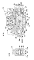
[도 1] 도 1A는, 본 발명의 제1 실시 형태의 출력 장치를 적용한 로봇 핸드 체인저(changer)의 해제 상태의 입면(立面)에서 본 단면도이다. 도 1B는, 도 1A 중의 1B-1B선의 단면도에 상당하는 도면이다. 도 1C는, 도 1A 중의 1C-1C선의 단면도에 상당하는 도면이다.
[도 2] 도 2A는, 상기 로봇 핸드 체인저의 고정 상태를 나타내며, 도 1A에 유사한 도면이다. 도 2B는, 도 1B에 유사한 도면이다.
[도 3] 도 3A 및 도 3B는, 각각, 클램프 대상물(툴 어댑터)이 재치된 본 발명의 일 실시 형태에 관계되는 스토커에, 도 1에 나타내는 출력 장치를 삽입한 상태를 나타내는 평면도 및 정면도이다.
[도 4] 도 4A는, 도 3A 중의 4A-4A선의 단면도에 상당하는 도면이고, 도 4B는, 도 3A 중의 4B-4B선의 단면도에 상당하는 도면이다. 어느 도면에 있어서도 출력 장치 및 클램프 대상물(툴 어댑터)의 도시를 생략하고 있다.
[도 5] 도 5는, 도 3에 나타내는 해제 상태로부터 출력 장치를 슬라이드 이동시키고 있었던 도중 상태를 나타내는 평면도이다.
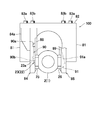
[도 6] 도 6은, 본 발명의 제2 실시 형태의 출력 장치를 적용한 로봇 핸드 체인저를 나타내며, 도 1A에 유사한 도면이다.BRIEF DESCRIPTION OF DRAWINGS FIG. 1A is a cross-sectional view of a robot hand changer to which an output device according to a first embodiment of the present invention is applied, viewed from an elevation of a released state; FIG. Fig. 1B is a view corresponding to a cross-sectional view taken along
[Fig. 2] Fig. 2A shows a fixed state of the robot hand changer, similar to Fig. 1A. Figure 2B is a similar view to Figure 1B.
Fig. 3A and 3B are a plan view and a front view, respectively, showing a state in which the output device shown in Fig. 1 is inserted into a stocker according to an embodiment of the present invention in which a clamp object (tool adapter) is placed .
4A is a cross-sectional view taken along
[Fig. 5] Fig. 5 is a plan view showing an intermediate state in which the output device is slid and moved from the released state shown in Fig. 3;
[Fig. 6] Fig. 6 shows a robot hand changer to which the output device of the second embodiment of the present invention is applied, similar to Fig. 1A.
도 1A 내지 도 2B는, 본 발명의 제1 실시 형태의 출력 장치를 적용한 로봇 핸드 체인저를 예시하고 있다. 우선, 도 1A 내지 도 1C에 기초하여 상기 로봇 핸드 체인저의 구조를 설명한다.1A and 2B illustrate a robot hand changer to which the output apparatus of the first embodiment of the present invention is applied. First, the structure of the robot hand changer will be described with reference to Figs. 1A to 1C.
또한, 이하의 설명에서 사용하는 「상부」, 「상방」, 「상하 방향」, 「수평 방향」이라는 방향을 나타내는 문언은, 도 1에 나타내는 방향으로 출력 장치가 있는 경우의 것으로서, 출력 장치 및 이를 구성하는 각 부품의 방향은, 이하의 설명에서 사용하는 방향을 나타내는 문언으로 한정되는 것은 아니다. 로봇 암의 선단은 다양한 방향으로 향하는 것이므로, 로봇 암의 선단에 장착된 출력 장치도 다양한 방향을 향하기 때문이다.The words indicating the directions of "top", "upward", "vertical direction", and "horizontal direction" used in the following description are those in the case where there is an output device in the direction shown in FIG. 1, The direction of each constituent component is not limited to a wording indicating a direction used in the following description. Since the tip of the robot arm is oriented in various directions, the output device mounted at the tip of the robot arm also faces various directions.
(출력 장치)(Output device)
상기 출력 장치의 하우징(1)은, 본체 부분으로서의 하우징 본체(2)와, 그 하우징 본체(2)의 상부로부터 상방으로 일체로 돌출된 통상(筒狀)의 플러그 부분(3)을 구비한다. 상기 하우징 본체(2) 내에 출력 장치의 구성 부재가 배치되며, 상기 플러그 부분(3)에 후술하는 클램프 기구(4)의 구성 부재가 설치된다. 하우징(1)(출력 장치)은, 도시를 생략하는 로봇 암의 선단에 장착된다.The
상기 하우징 본체(2)에 제1 가이드구멍(11)이 상하 방향으로 형성된다. 또한, 그 하우징 본체(2)에 제2 가이드구멍(12)이 수평 방향으로 형성되고, 그 제2 가이드구멍(12)이 제1 가이드구멍(11)에 교차되고 있다.A first guide hole (11) is formed in the housing main body (2) in a vertical direction. A
상기 제1 가이드구멍(11)과 상기 플러그 부분(3)의 통공(筒孔)(3a)에, 출력 로드(21)가 상하 방향(축심 방향)으로 이동 가능하게 삽입된다. 또한, 상기 제2 가이드구멍(12)에 구동용 조작 로드(22)가 수평 방향(축심 방향)으로 이동 가능하게 삽입된다. 이 조작 로드(22)는, 동축(同軸) 배치되는 고정측 조작 로드(23)와 해제측 조작 로드(24)로 구성된다. 고정측 조작 로드(23)의 단부인 고정 조작부(23a)는, 해제측 조작 로드(24)의 단부인 해제 조작부(24a)보다 작다. 고정측 조작 로드(23)는, 제2 가이드구멍(12)에 삽입됨과 아울러 하우징 본체(2)의 측방단(側方端)에 고정된 가이드통(25)에도 삽입된다. 또한, 고정측 조작 로드(23)의 중도부(中途部)에는 원판 형상의 플랜지부(23b)가 마련된다. 해제측 조작 로드(24)는, 제2 가이드구멍(12)에 삽입됨과 아울러 하우징 본체(2)의 상기 측방단과는 반대측의 측방단에 고정된 가이드통(26)에도 삽입된다. 또한, 가이드통(25, 26)은 하우징(1)을 구성하는 일 부품이다.An
출력 로드(21)의 하반 부분(기단측 부분)에는, 수평 방향 또한 상하 방향으로 뻗는 수용홈(31)이 형성된다. 그 수용홈(31)에는, 고정측 조작 로드(23)에 마련한 삽입부(32)가 끼워진다.At the lower half portion (base end side portion) of the
또한, 수용홈(31)의 양측벽(31a, 31a)에는, 안내 부재로서의 핀 부재(35)의 길이 방향의 양단부가, 래디얼 베어링(36)을 통해 회전 가능하게 지지된다. 상기 핀 부재(35)에 대응시켜서, 고정측 조작 로드(23)의 상기 삽입부(32)에 캠홈(38)이 형성된다. 그 캠홈(38)은, 수평홈 부분(39)과, 우하 방향으로 경사진 구동홈 부분(40)을 갖고, 이 구동홈 부분(40)은, 고정측 조작 로드(23)의 축심 방향에 대한 경사 각도가 서로 다른 제1 구동홈 부분(40a)과 제2 구동홈 부분(40b)으로 구성된다. 제2 구동홈 부분(4Ob)의 경사 각도(예를 들면, 30°)는, 제1 구동홈 부분(40a)의 경사 각도(예를 들면, 45°)보다 작다. 상기 캠홈(38)이 핀 부재(35)의 길이 방향의 중앙부에 끼워져(결합되어) 있다. 또한, 상기 플러그 부분(3)의 도중(途中) 높이부에 설치한 스프링 시트(43)와 출력 로드(21)의 도중 높이부 사이에 고정 스프링(44)이 장착된다.Both end portions of the
하우징 본체(2) 내의 우측방 부분에는, 고정측 조작 로드(23)의 축심 방향으로의 이동을 도와주는 배력 기구(5)가 설치된다. 이 배력 기구(5)는, 다음과 같이 구성된다.In the right side portion in the housing
고정측 조작 로드(23)의 외주에는, 결합 부재로서의 결합 볼(51)이 끼워지는 복수의 결합 오목부(52)가, 둘레 방향으로 소정의 간격을 두고 형성된다. 그 결합 오목부(52) 중의 하우징 본체(2) 중심측에 형성된 캠면(52a)은, 고정측 조작 로드(23)의 단부로 향함에 따라 축심에 가까워지도록 형성된다. 또한, 상기 가이드통(25)의 반경 방향 내측의 통벽(筒壁)(25a)에는, 고정측 조작 로드(23)의 반경 방향으로의 결합 볼(51)의 이동을 허용하지만, 고정측 조작 로드(23)의 축심 방향으로의 결합 볼(51)의 이동을 제한하는 결합 부재 지지부로서의 지지 구멍(53)이, 상기 결합 오목부(52)에 대응시켜 복수 형성된다.A plurality of engaging
또한, 상기 가이드통(25)의 공동(hollow)(27) 부분에는, 결합 볼(51)을 압압하는 통상의 압압 부재(54)가 배치된다. 압압 부재(54)의 내주(內周)에 형성된 배력면(54a)은, 고정측 조작 로드(23)의 단부로 향함에 따라 축심에 가까워지도록 형성되어 있으며, 그 수평 방향(축심 방향)에 대한 경사 각도는, 상기 캠면(52a)의 수평 방향(축심 방향)에 대한 경사 각도보다 작다. 압압 부재(54)와 가이드통(25)의 공동(27) 부분의 저면 사이에는 하우징 본체(2)의 중앙측으로 압압 부재(54)를 부세하는 스프링(55)이 들어 있다. 또한, 고정측 조작 로드(23)의 외주의, 결합 오목부(52)보다 약간 하우징 본체(2) 중심측에 가까운 부분에는, 환상(環狀)의 결합홈(56)이 마련되어 있다.A common pressing
상기 클램프 기구(4)는, 다음과 같이 구성되어 있다.The
상기 플러그 부분(3)의 주벽(周壁)의 상부에, 횡 방향의 관통 구멍(61)이 둘레 방향으로 소정의 간격을 두고 형성되며, 각 관통 구멍(61)에 결합 볼(62)이 삽입된다. 출력 로드(21)의 상부에는, 아래 방향으로 좁아지는 테이퍼 외주면(63)과 퇴피(退避)홈(64)이 상하로 형성된다. 플러그 부분(3)의 주벽의 하반부에 콜릿(65)이 끼워진다. 그 콜릿(65)은, 상하 방향으로 형성된 슬릿(66)을 갖고, 반경 방향으로 축소 가능하며 그것의 탄성 복원력에 의해 반경 방향으로 확대 가능하게 구성되어 있다. 상기 콜릿(65)이 진출(進出) 스프링(67)에 의해 상방으로 부세된다. 또한, 상기 진출 스프링(67)은, 둘레 방향으로 소정의 간격을 두고 복수 배치되어 있다.A transverse through
(클램프 대상물(툴 어댑터))(Clamp object (tool adapter))
또한, 출력 장치로 클램프되는 클램프 대상물로서의 툴 어댑터(70)의 하면에 삽입 구멍(71)이 개구(開口)된다. 그 삽입 구멍(71)의 내주면에 결합 구멍(72)과 테이퍼 위치결정 구멍(73)이 상하로 형성된다. 이 툴 어댑터(70)에는, 도시를 생략하는 각종 공구가 장착된다.Further, the
(스토커)(stalker)
도 3A 내지 도 5는, 본 발명의 출력 시스템을 구성하는 스토커(100)의 일 실시 형태를 나타내고 있다. 도 3A 내지 도 4B에 기초하여 스토커(100)의 구조를 설명한다.3A to 5 show an embodiment of the
테이블 상에 고정되는 한 쌍의 다리부(81, 81)의 이면에 지지 벽(82)이 볼트(83a)로 입설(立設) 고정된다. 이 지지 벽(82)에는, 수평 방향으로 뻗도록 한 쌍의 받침 부재(84, 85)가 볼트(83b)로 고정된다. 이들 받침 부재(84, 85)의 지지 벽(82)으로의 고정은 리브(84a, 85a)로 보강되어 있다.The
한쪽 받침 부재(84) 하부의 받침 부재(85)와의 대향면에는 수평 방향으로 뻗는 홈 형상의 재치대부(86)가 형성된다. 마찬가지로, 다른쪽 받침 부재(85) 하부의 받침 부재(84)와의 대향면에도 수평 방향으로 뻗는 홈 형상의 재치대부(87)가 형성된다. 상기 툴 어댑터(70)는, 이들 재치대부(86, 87)의 개방단(開放端)으로부터 삽입되어 재치대부(86, 87) 상에 놓인다. 또한, 도 3B에 나타내는 툴 어댑터(70)의 상하 방향의 방향은, 도 1A에 나타내는 툴 어댑터(70)의 방향과 상하 반대이다.A groove-shaped
또한, 툴 어댑터(70)는, 수평 방향으로 뻗는 홈 형상으로 형성되는 재치대부(86)와 재치대부(87)에 걸쳐 재치되는 것에 대신하여, 평면 모양으로 형성된 재치대부 상에 재치되어도 된다.The
또한, 받침 부재(84) 상부의 받침 부재(85)와의 대향면에는 수평 방향으로 뻗는 홈 형상의 가이드홈(88)이 형성되고, 마찬가지로, 받침 부재(85) 상부의 받침 부재(84)와의 대향면에도 수평 방향으로 뻗는 홈 형상의 가이드홈(89)이 형성된다. 상기 가이드홈(88) 내에는 수평 방향으로 뻗는 고정 가이드홈(90)이 더 마련되며, 그 단부는 상하 방향으로 뻗는 홈(90a)으로 되어 있다. 고정 가이드홈(90)의 홈(90a)과는 반대측의 단부에는, 상기 고정측 조작 로드(23)의 단부(고정 조작부(23a))가 접촉하는 테이퍼 형상의 테이퍼면(90b)이 형성된다. 또한, 상기 가이드홈(89) 내에는 수평 방향으로 뻗는 해제 가이드홈(91)이 더 마련되며, 그 일부에는 상기 해제측 조작 로드(24)의 단부(해제 조작부(24a))가 접촉하는 테이퍼 형상의 테이퍼면(91a)이 형성된다. 고정 가이드홈(90)의 폭은, 상기 해제측 조작 로드(24)의 단부는 통과 불가이고 상기 고정측 조작 로드(23)의 단부가 통과 가능한 치수로 되며, 해제 가이드홈(91)의 폭은, 상기 해제측 조작 로드(24)의 단부가 통과 가능한 치수로 되는, 즉, 고정 가이드홈(90)과 해제 가이드홈(91)은 크기가 다르다.A groove-shaped
(고정·해제 조작)(Fixing / releasing operation)
상기 스토커(100)를 이용한 툴 어댑터(70)의 고정·해제 조작에 대해 설명한다. 또한, 도 1A, 도 2A에 나타내는 출력 장치 및 툴 어댑터(70)의 상하 방향의 방향은, 도 3A 내지 도 5에 나타내는 출력 장치 및 툴 어댑터(70)의 방향과 상하 반대인 것을 먼저 언급해 둔다.The fixing and releasing operation of the
우선, 도 1A의 해제 상태에서는, 고정측 조작 로드(23)의 단부가 가이드통(25)으로부터 돌출되고(오른쪽으로 후퇴되고), 이에 의해, 출력 로드(21)가 고정 스프링(44)에 대항하여 상승되며(도 3B에서는 하강되어 있다), 결합 볼(62)이 퇴피홈(64)을 향하여 반경 방향의 안쪽으로 이동 가능하게 되어 있다(도 1A에서는, 상기 결합 볼(62)이 이미 이동된 상태를 나타내고 있다). 배력 기구(5)를 구성하는 결합 볼(51)은, 압압 부재(54)로 눌려져, 고정측 조작 로드(23)의 외주에 형성된 결합홈(56)에 끼워져 있다.1A, the end of the fixed-
도 1A의 해제 상태로부터 도 2A의 고정 상태로 전환할 때에는, 로봇 암을 움직여서, 우선, 도 3A, 도 3B에 나타내는 바와 같이, 스토커(100)의 상방으로부터 그 받침 부재(84)에 형성된 홈(90a)에, 출력 장치의 고정측 조작 로드(23)의 단부(고정 조작부(23a))를 삽입하면서, 스토커(100)의 재치대부(86, 87) 상에 재치된 툴 어댑터(70)의 삽입 구멍(71)에 출력 장치의 플러그 부분(3)을 삽입해 두고, 상기 콜릿(65)의 테이퍼 형상의 외주면을 툴 어댑터(70)의 테이퍼 위치결정 구멍(73)에 끼워 맞춘다.3A to 3B, the robot arm is moved so that a groove (not shown) formed in the
이어서, 도 5에 나타내는 바와 같이, 스토커(100)의 가이드홈(88, 89)을 따라 지지 벽(82)으로부터 멀어지는 방향으로 출력 장치를 슬라이드시켜 간다. 출력 장치의 고정측 조작 로드(23)의 단부가 고정 가이드홈(90)의 테이퍼면(가이드면)(9Ob) 부분에 도달하면, 그 단부는 곧 테이퍼면(90b)에 접촉하고, 더 슬라이드시켜 가면 테이퍼면(90b)으로부터의 반력(反力)으로 결합 볼(51)이 결합홈(56)으로부터 빠지며, 고정측 조작 로드(23)는 가이드통(25) 안으로 밀려 들어간다. 고정측 조작 로드(23)가 소정 스트로크만큼 압입되면, 스프링(55)으로 부세되어 있는 압압 부재(54)의 확경(擴徑) 선단 부분에서 결합 볼(51)은 결합 오목부(52)의 캠면(52a)으로 밀려 나가, 배력 구동(증력 구동)이 개시된다. 압압 부재(54)의 배력면(54a)이 결합 볼(51)과 캠면(52a)을 통해 고정측 조작 로드(23)를 강력하게 가이드통(25) 안으로 압입해 간다.5, the output device is slid along the
이에 의해, 고정측 조작 로드(23)의 구동홈 부분(40)이 핀 부재(35)를 통해 출력 로드(21)를 상승시킨다(도 1A에서는 하강). 그리하면, 그 상승력과 고정 스프링(44)의 합력에 의해, 출력 로드(21)의 테이퍼 외주면(63)이 결합 볼(6)과 결합 구멍(72)을 통해 툴 어댑터(70)를 인상한다(도 1A에서는 인하). 이에 의해, 툴 어댑터(70)의 테이퍼 위치결정 구멍(73)이, 콜릿(65)을 축경(縮徑)시켜서 해당 콜릿(65)의 내주면을 플러그 부분(3)의 외주면에 밀착시킴과 아울러, 콜릿(65)을 진출 스프링(67)에 대항하여 상승시키고, 툴 어댑터(70)의 상면이 하우징 본체(2)의 하면에 압압된다.Thus, the
구동홈 부분(40) 중의 제2 구동홈 부분(40b)의 상기 경사 각도는, 제1 구동홈 부분(40a)의 상기 경사 각도보다 작으므로, 핀 부재(35)가 제2 구동홈 부분(40b)의 위치에 이르면, 제1 구동홈 부분(40a)을 통과해 있을 때보다 큰 힘으로 출력 로드(21)가 결합 볼(62)을 압압한다. 또한, 핀 부재(35)가 제2 구동홈 부분(40b)에 위치하는 것과, 결합 볼(51)이 배력면(54a)에 위치하는 것이 겹쳐 있기 때문에, 상기 배력 기구(5)에 의해 배력 구동된 고정측 조작 로드(23)가, 핀 부재(35)와 제2 구동홈 부분(40b)을 통해 출력 로드(21)를 결합 볼(62)로 강력하게 압압시킨다.The inclination angle of the second
또한, 상기 고정 상태에서, 스프링(55)의 부세력이 배력 기구(5)의 쐐기 작용을 통해 고정 상태를 기계적으로 유지하므로, 그 고정 상태가 확실히 유지된다.Further, in the fixed state, the biasing force of the
도 2A의 고정 상태로부터 도 1A의 해제 상태로 전환할 때에는, 툴 어댑터(70)를 고정한 출력 장치를, 해제 상태로부터 고정 상태로 전환하는 경우와는 반대로, 스토커(100)의 받침 부재(84, 85)의 개방단으로부터 스토커(100) 내로 상기 가이드홈(88, 89)을 따라 들어간다. 출력 장치의 해제측 조작 로드(24)의 단부가 해제 가이드홈(91)의 테이퍼면(9a) 부분에 도달하면, 그 단부는 곧 테이퍼면(가이드면)(91a)에 접촉하고, 더 슬라이드시켜 가면 테이퍼면(91a)으로부터의 반력으로 결합 볼(51)이 결합 오목부(52)로부터 빠지며, 고정측 조작 로드(23)와 일체적으로 이동하는 해제측 조작 로드(24)는 가이드통(26) 안으로 압입되어 간다. 가이드통(26) 안으로 해제측 조작 로드(24)가 완전히 압입되면, 도 1A에 나타내는 해제 상태가 된다. 그 후, 출력 장치를 상방으로 이동시킴으로써 스토커(100)로부터 출력 장치를 빼낸다.2A to the release state shown in Fig. 1A, as opposed to the case where the output device to which the
또한, 상기 반력에 의한 해제측 조작 로드(24)의 가이드통(26) 내로의 압입력은, 출력 장치의 슬라이드 방향에 대한 상기 테이퍼면(91a)의 경사 각도를 크게 하거나 작게 하거나 함으로써 변화한다. 테이퍼면(91a)의 경사 각도를 작게 하면, 출력 장치를 슬라이드시키는 방향으로 부여하는 힘이 작아도, 충분한 상기 압입력을 얻을 수 있다.The pressure input of the releasing-
(작용·효과)(Action / effect)
상기 구성의 출력 장치에서는, 조작 로드(22)의 축심 방향으로의 이동을 배력 기구(5)에 의해 도와준다. 그 때문에, 작은 힘으로 조작 로드(22)를 이동시킬 수 있으므로, 공구·전동기 등의 큰 힘을 발생시키는 구동 수단을 이용하는 일 없이, 출력 장치와 툴 어댑터(70)의 고정 조작을 행할 수 있다. 또한, 탄성력이 큰 상기 스프링(55)을 이용하면, 배력 구동이 시작되면 외력이 없어도 조작 로드(22)는 이동한다. 「조작 로드(22)의 축심 방향으로의 이동을 배력 기구(5)에 의해 도와준다」란, 반력 등의 외력과 배력 기구에 의한 배력을 조작 로드(22)에 대해 동시에 작용시키는 경우뿐만 아니라, 반력 등의 외력을 조작 로드(22)에 부여함으로써 조작 로드(22)가 조금 이동을 한 후는 배력 기구에 의한 배력만으로 조작 로드(22)를 이동시키는 경우도 포함한다.In the output apparatus having the above-described configuration, the operation mechanism (5) helps the operation rod (22) to move in the axial direction. Therefore, since the operating
또한, 구동홈 부분(40) 중의 제2 구동홈 부분(40b)의 경사 각도가, 제1 구동홈 부분(40a)의 경사 각도보다 작게 되어 있으므로, 핀 부재(35)가 제2 구동홈 부분(40b)의 위치에 이르면, 제1 구동홈 부분(40a)을 통과해 있을 때보다 큰 힘으로 출력 로드(21)가 결합 볼(62)을 압압한다.Since the inclination angle of the second
나아가, 고정 조작 시의, 핀 부재(35)가 제2 구동홈 부분(40b)에 위치하는 것과, 결합 볼(51)이 배력면(54a)에 위치하는 것이 겹쳐 있다. 이 때문에, 상기 배력 기구(5)에 의해 배력 구동된 조작 로드(23)가, 핀 부재(35)와 제2 구동홈 부분(40b)을 통해 출력 로드(21)를 결합 볼(62)로 강력하게 압압시킨다.Further, the
또한, 상기 고정 상태에서, 스프링(55)의 부세력이 배력 기구(5)의 쐐기 작용을 통해 고정 상태를 기계적으로 유지하므로, 그 고정 상태가 확실히 유지된다.Further, in the fixed state, the biasing force of the
또한, 조작 로드(22)를 구성하는 고정측 조작 로드(23)는, 하우징 본체(2)에 형성된 제2 가이드구멍(12)에 더하여 가이드통(25)의 통벽(25a)의 내주면에서도 지지되므로, 가이드 특성이 뛰어나다. 마찬가지로, 해제측 조작 로드(24)는, 하우징 본체(2)에 형성된 제2 가이드구멍(12)에 더하여 가이드통(26)의 내주면에서도 지지되므로, 가이드 특성이 뛰어나다. 고정측 조작 로드(23)의 중도부에 마련된 상기 플랜지부(23b)는, 제2 가이드구멍(12)에 의한 가이드 특성을 더 향상시킨다.The fixed
(제2 실시 형태)(Second Embodiment)
도 6은, 본 발명의 제2 실시 형태의 출력 장치를 적용한 로봇 핸드 체인저를 나타내고 있다. 이 실시 형태에서는, 상기 제1 실시 형태의 구성 부재와 같은 부재(또는 유사한 부재)에는 원칙적으로 동일한 참조 숫자를 붙여 설명한다.Fig. 6 shows a robot hand changer to which the output device of the second embodiment of the present invention is applied. In this embodiment, members (or similar members) that are the same as the constituent members of the first embodiment will be described with the same reference numerals in principle.
도 6의 제2 실시 형태는, 상기 제1 실시 형태와는 다음의 점에서 다르다.The second embodiment of Fig. 6 is different from the first embodiment in the following points.
제1 실시 형태의 상기 도 1A에서는, 가이드통(25)의 반경 방향 내측의 통벽(25a)에 상기 결합 부재 지지부로서의 지지 구멍(53)이 마련되어 있었지만, 제2 실시 형태의 도 6에서는, 가이드통(28)의 축심 방향에 있어서의 결합 볼(51)과 대향하는 면에 상기 결합 부재 지지부로서의 볼록부(28a)가 형성되어 있고, 해당 가이드통(28)은, 상기 제1 실시 형태의 상기 통벽(25)이나 지지 구멍(53)을 갖지 않는다.1A of the first embodiment, the
또한, 제2 실시 형태에서는, 결합 볼(51)과 고정측 조작 로드(23)의 삽입부(32) 사이에 압압 부재(54)가 배치되고, 압압 부재(54)를 부세하는 스프링(55)은, 압압 부재(54)를 출력 장치의 바깥쪽으로 부세하도록 하우징 본체(2) 안에 배치되어 있다.In the second embodiment, a pressing
(변형 예)(Modified example)
상기 각 실시 형태는, 다음과 같이 변경 가능하다.The above-described embodiments can be modified as follows.
출력 장치의 상태를 고정 상태 또는 해제 상태로 전환하는 것에, 즉, 조작 로드(22)를 축심 방향으로 이동시키는 것에, 스토커(100)를 이용하는 대신에 조작 로드(22)의 단부를 적당한 임의 물체의 물체면에 닿게 하거나(접촉시키거나), 유체압 실린더나 전동기 등의 액츄에이터를 이용하거나, 손으로 밀거나 당기거나 함으로써 조작 로드(22)를 축심 방향으로 이동시켜도 된다.The end of the
상기 조작 로드(22)는, 고정측 조작 로드(23)와 해제측 조작 로드(24)로 나뉘어 있지만, 고정측 조작 로드(23)와 해제측 조작 로드(24)가 일체이어도 된다. 이 경우, 일체로 형성된 조작 로드(22)의 양단부 중 어느 한쪽 단부에만 플랜지 형상이나 구멍 형상 등의 걸림부를 마련해서, 이 걸림부에 물체를 걸어 조작 로드(22)를 밀고 당김으로써, 고정 조작, 해제 조작을 행해도 된다.The operating
상기 배력 기구(5)는 고정 조작부(23a)측에 설치되어 있지만, 고정 조작부(23a)측에 설치하는 것에 대신하여 해제 조작부(24a)측의 하우징 본체(2) 내에 배력 기구를 설치해도 된다. 또한, 배력 기구(5)를 구성하는 스프링(55)이 결합 볼(51)을 부세하는 방향을, 조작 로드(22)의 축심 방향으로 하는 것에 대신하여, 이 축심 방향에 직교하는 방향 등에 교차하는 방향으로 해도 된다.The
출력 로드(21)의 축심 방향과 조작 로드(22)의 축심 방향은, 직교시키는 것에 대신하여, 그 직교 상태보다도 소정 각도로 경사진 상태로 교차시켜도 된다. 나아가, 출력 로드(21)의 클램프 기구(4)와는 반대측의 단부에 상기 배력 기구(5)와 같은 기구를 설치함과 아울러 그 끝을 제1 가이드구멍(11)으로부터 돌출시킴으로써, 출력 로드(21)의 단부를 조작 로드로 해도 된다. 즉, 출력 로드와 조작 로드를 일체적으로 해도 된다. 이 경우, 출력 로드의 축심 방향과 조작 로드의 축심 방향은 같은 방향이 된다.The axial center direction of the
출력 로드(21) 및 제1 가이드구멍(11)을 하방(도 1A에 있어서의 방향)으로 연장하고, 연장한 단부에도 상기 클램프 기구(4)를 설치해도 된다. 즉, 2개의 클램프 기구를 조작 로드(22)를 사이에 두도록 해서 대향 배치해도 된다.The
상기 핀 부재(35)는, 수용홈(31)의 양측벽(31a, 31a)에 회전 가능하게 지지되는 것에 대신하여, 상기 양측벽(31a, 31a)에 고정되어도 된다. 나아가, 이 경우, 핀 부재(35)의 길이 방향 중앙부에 래디얼 베어링을 끼워, 이 길이 방향 중앙부가 해당 래디얼 베어링을 통해 상기 캠홈(38)에 끼워 맞춤(결합)되어도 된다. 또한, 상기 안내 부재로서, 예시한 핀 부재(35)를 대신하여, 볼이나 키 등을 사용해도 된다. 래디얼 베어링(36)은, 롤러 등으로 변경 가능하다.The
출력 로드(11)에 수용홈(31)을 형성함과 아울러 조작 로드(22)(고정측 조작 로드(23))에 삽입부(32)를 마련하는 것에 대신하여, 출력 로드(11)에 삽입부를 마련함과 아울러 조작 로드(22)(고정측 조작 로드(23))에 수용홈을 형성해도 된다.In place of forming the receiving
캠홈(38)의 상기 수평홈 부분(39)은 왼쪽 방향으로 개구되어 있지만, 수평홈 부분(39)의 왼쪽 부분(단부)이 막혀 있어도 된다.Although the
출력 로드(11)는, 하방(도 1A에 있어서의 방향)으로 고정 구동되는 것에 대신하여, 상방(도 1A에 있어서의 방향)으로 고정 구동되도록 구성되어도 된다. 이 경우, 캠홈(38)의 구동홈 부분(40)의 경사 방향을 변경하면 된다. 또한, 구동홈 부분(40)의 경사 각도는 끝에서부터 끝까지 일정해도 된다.The
상기 클램프 기구(4)는, 결합 볼(62)을 이용한 기구이지만, 클램프 기구로서, 일본 특개 2014-030892호 공보에 기재된 바와 같은 클램프 기구를 사용해도 된다.Although the
로봇 핸드 체인저에 출력 장치를 적용하는 것에 대신하여, 다양한 종류의 클램프에 출력 장치를 적용해도 된다.Instead of applying an output device to the robot hand changer, the output device may be applied to various types of clamps.
그 외에, 당업자가 상정할 수 있는 범위에서 여러 가지 변경을 행할 수 있는 것은 물론이다.It goes without saying that various changes can be made within the range that can be assumed by those skilled in the art.
1:하우징
5:배력 기구
21:출력 로드
22:조작 로드
23a:고정 조작부
24a:해제 조작부
35:안내 부재(핀 부재)
38:캠홈
40:구동홈 부분
51:결합 부재(결합 볼)
52:결합 오목부
52a:캠면
53:결합 부재 지지부(지지 구멍)
54:압압 부재
54a:배력면
55:스프링
70:툴 어댑터(클램프 대상물)
86, 87:재치대부
90, 91:가이드홈
90b, 91a:가이드면(테이퍼면)
100:스토커1: housing 5:
21: Output load 22: Operation load
23a: Fixed operating
35: guide member (pin member) 38: cam groove
40: driving groove portion 51: engaging member (engaging ball)
52: engaging
53: coupling member supporting portion (supporting hole) 54:
54a: an energizing surface 55: a spring
70: tool adapter (clamp object) 86, 87:
90, 91:
100: Stocker
Claims (4)
상기 하우징(1)과 상기 조작 로드(22) 사이에 설치되는 배력(倍力) 기구(5)로서, 상기 조작 로드(22)의 상기 축심 방향으로의 이동을 도와주는 배력(倍力) 기구(5)와,
상기 조작 로드(22)에 의해 상기 축심 방향 또는 상기 축심 방향과 교차하는 방향으로 이동하게 되는 출력 로드(21)를 구비하며,
상기 배력 기구(5)는,
결합 부재(51)와,
상기 조작 로드(22)의 외주(外周)에 형성된, 상기 결합 부재(51)가 끼워지는 결합 오목부(52)로서, 상기 결합 부재(51)가 결합하는 캠면(52a)을 가지는 결합 오목부(52)와,
상기 조작 로드(22)의 반경 방향으로의 상기 결합 부재(51)의 이동을 허용하지만 상기 조작 로드(22)의 축심 방향으로의 상기 결합 부재(51)의 이동을 제한하는 결합 부재 지지부(53)와,
스프링(55)에 의해 부세(付勢)됨으로써 상기 결합 부재(51)를 압압하는 압압(押壓) 부재(54)로서, 상기 결합 부재(51)가 결합하는 배력면(倍力面)(54a)을 가지는 압압 부재(54)를 가지는 것을 특징으로 하는, 출력 장치.An operation rod 22 inserted in the housing 1 so as to be movable in the axial direction so as to be movable in the axial direction by an external force applied to an end portion of the operation rod 22 in the axial direction, A rod 22,
A boosting mechanism 5 installed between the housing 1 and the operating rod 22 is provided with a boost mechanism for assisting movement of the operating rod 22 in the axial direction 5)
And an output rod (21) which is moved by the operating rod (22) in a direction intersecting the axis direction or the axis direction,
The power mechanism (5)
A coupling member 51,
A coupling concave portion 52 in which the coupling member 51 is fitted and which is formed on an outer periphery of the operation rod 22 is formed as a coupling concave portion 52 having a cam surface 52a to which the coupling member 51 is coupled 52,
A coupling member supporting portion 53 for permitting the movement of the coupling member 51 in the radial direction of the operating rod 22 but restricting the movement of the coupling member 51 in the axial direction of the operating rod 22, Wow,
(Pushing member) 54 that pushes the engaging member 51 by being biased by the spring 55. The pressing surface 54a of the engaging member 51 And a pressing member (54) having a pressing member (54).
상기 출력 로드(21)의 기단(基端)측 부분에 설치된 안내 부재(35)와,
상기 안내 부재(35)에 직접 또는 간접적으로 결합되도록 상기 조작 로드(22)에 마련된 캠홈(38)으로서, 상기 조작 로드(22)의 축심 방향의 양단 중 어느 하나의 일단으로 향함에 따라 해당 축심으로부터 멀어지는 구동홈 부분(40)을 가지는 캠홈(38)을 구비하는 것을 특징으로 하는, 출력 장치.The method according to claim 1,
A guide member 35 provided at a proximal end side portion of the output rod 21,
A cam groove (38) provided in the operating rod (22) so as to be directly or indirectly coupled to the guide member (35) And a cam groove (38) having a drive groove portion (40) that is away from the cam groove (38).
상기 조작 로드(22)를 상기 축심 방향으로 이동시키기 위한 가이드면(90b, 91a)을 가지는 스토커(100)를 구비하며,
상기 스토커(100)는,
상기 출력 장치로 클램프되는 클램프 대상물(70)이 재치(載置)되는 재치대부(86, 87)와,
테이퍼 형상의 상기 가이드면(90b, 91a)이 내면에 마련된 가이드홈(90, 91)으로서, 상기 조작 로드(22)의 단부의 안내부가 되는 가이드홈(90, 91)을 갖고 있으며,
상기 하우징(1)으로부터 돌출하는 상기 조작 로드(22)의 단부를 상기 가이드홈(90, 91)에 통과시킴으로써 테이퍼 형상의 상기 가이드면(90b, 91a)에 접촉시켜 상기 조작 로드(22)를 상기 축심 방향으로 이동시키는 것을 특징으로 하는, 출력 시스템.An output device according to claim 1 or 2,
And a stocker (100) having guide surfaces (90b, 91a) for moving the operating rod (22) in the axial direction,
The stocker (100)
(86, 87) on which the clamp object (70) clamped by the output device is placed,
The tapered guide surfaces 90b and 91a have guide grooves 90 and 91 provided on the inner surface thereof and guide grooves 90 and 91 for guiding the end portions of the operation rod 22,
The end of the operating rod 22 protruding from the housing 1 is passed through the guide grooves 90 and 91 so as to contact the tapered guide surfaces 90b and 91a, Axis direction of the output shaft.
상기 조작 로드(22)의 한쪽 단부인 고정 조작부(23a)와, 다른쪽 단부인 해제 조작부(24a)의 크기가 다르고,
상기 가이드홈(90, 91)은, 상기 고정 조작부(23a)에 대응하는 고정 가이드홈(90)과, 상기 해제 조작부(24a)에 대응하는 해제 가이드홈(91)으로 구성되는 것을 특징으로 하는, 출력 시스템.The method of claim 3,
The fixing operation portion 23a at one end of the operating rod 22 and the releasing operation portion 24a at the other end are different in size,
Wherein the guide grooves 90 and 91 are constituted by a fixed guide groove 90 corresponding to the fixed operation portion 23a and a release guide groove 91 corresponding to the release operation portion 24a. Output system.
Applications Claiming Priority (3)
| Application Number | Priority Date | Filing Date | Title |
|---|---|---|---|
| JP2015038069A JP6353796B2 (en) | 2015-02-27 | 2015-02-27 | Output device and output system |
| JPJP-P-2015-038069 | 2015-02-27 | ||
| PCT/JP2016/055475 WO2016136821A1 (en) | 2015-02-27 | 2016-02-24 | Output device and output system |
Publications (2)
| Publication Number | Publication Date |
|---|---|
| KR20170120574A true KR20170120574A (en) | 2017-10-31 |
| KR102282819B1 KR102282819B1 (en) | 2021-07-27 |
Family
ID=56788755
Family Applications (1)
| Application Number | Title | Priority Date | Filing Date |
|---|---|---|---|
| KR1020177020696A KR102282819B1 (en) | 2015-02-27 | 2016-02-24 | Output device and output system |
Country Status (6)
| Country | Link |
|---|---|
| US (1) | US10166685B2 (en) |
| EP (1) | EP3263294B1 (en) |
| JP (1) | JP6353796B2 (en) |
| KR (1) | KR102282819B1 (en) |
| CN (1) | CN107405773B (en) |
| WO (1) | WO2016136821A1 (en) |
Families Citing this family (8)
| Publication number | Priority date | Publication date | Assignee | Title |
|---|---|---|---|---|
| ITUB20155846A1 (en) * | 2015-11-24 | 2017-05-24 | Gimatic S R L | TOOL CHANGE DEVICE |
| US11568920B2 (en) | 2017-08-02 | 2023-01-31 | Samsung Electronics Co., Ltd. | Dual row-column major dram |
| US11584023B2 (en) * | 2018-08-21 | 2023-02-21 | William George Bolton | Separable robotic interface |
| JP7127836B2 (en) * | 2019-02-13 | 2022-08-30 | 株式会社コスメック | tool changer |
| JP7217946B2 (en) * | 2019-05-08 | 2023-02-06 | 株式会社コスメック | Material changer |
| CN111940820B (en) * | 2020-08-07 | 2021-08-24 | 国网江苏省电力有限公司常州供电分公司 | Universal communication interface convenient for replacing and locking |
| JP2022167131A (en) * | 2021-04-22 | 2022-11-04 | Smc株式会社 | End effector exchanger |
| EP4215319A1 (en) * | 2022-01-19 | 2023-07-26 | Schunk GmbH & Co. KG Spann- und Greiftechnik | Automatically and manually operated jaw change system |
Citations (2)
| Publication number | Priority date | Publication date | Assignee | Title |
|---|---|---|---|---|
| KR20030040104A (en) * | 2001-11-13 | 2003-05-22 | 가부시키가이샤 코스멕 | Rotary clamp |
| JP2010105111A (en) | 2008-10-29 | 2010-05-13 | Nabeya Co Ltd | Fastening device |
Family Cites Families (19)
| Publication number | Priority date | Publication date | Assignee | Title |
|---|---|---|---|---|
| JPH05169383A (en) * | 1991-12-24 | 1993-07-09 | Nitta Ind Corp | Falling preventive device of automatic tool changing coupler |
| US5649956A (en) * | 1995-06-07 | 1997-07-22 | Sri International | System and method for releasably holding a surgical instrument |
| US5814038A (en) * | 1995-06-07 | 1998-09-29 | Sri International | Surgical manipulator for a telerobotic system |
| CN1139458C (en) * | 1996-12-02 | 2004-02-25 | 3R系统国际有限公司 | Tension system |
| JP2000108092A (en) * | 1998-10-05 | 2000-04-18 | Press Center:Kk | Punch retainer device for press |
| JP2000317541A (en) * | 1999-05-13 | 2000-11-21 | Amada Co Ltd | Center locationg pin device of working machine |
| CN1486403A (en) * | 2001-12-14 | 2004-03-31 | ������������ʽ���� | Propulsion converting device |
| JP3868873B2 (en) * | 2002-09-18 | 2007-01-17 | ニッタ株式会社 | Detachable mechanism |
| US20090160106A1 (en) * | 2004-10-12 | 2009-06-25 | Efficient Manufacturing System Integration | Apparatus and method for simultaneous usage of multiple die casting tools |
| CN2778444Y (en) * | 2004-10-14 | 2006-05-10 | 陈月辉 | Quick safety connecting mechanism |
| US8366592B2 (en) * | 2007-11-30 | 2013-02-05 | Cinetic Automation Corp. | Quick change spindle |
| JP5593866B2 (en) * | 2010-06-11 | 2014-09-24 | 富士通株式会社 | Tool change mechanism |
| JP4945681B1 (en) * | 2010-11-24 | 2012-06-06 | 株式会社コスメック | Cylinder device with booster mechanism |
| JP5238845B2 (en) * | 2011-03-31 | 2013-07-17 | 通則 竹元 | Slide core device |
| JP5631816B2 (en) * | 2011-07-06 | 2014-11-26 | 株式会社神戸製鋼所 | Welding tip change device, welding tip change system and welding tip change method |
| US9541194B2 (en) * | 2012-02-16 | 2017-01-10 | Kosmek Ltd. | Cylinder device with force multiplier |
| TWI508831B (en) * | 2013-01-28 | 2015-11-21 | Prec Machinery Res & Dev Ct | A joint device for a parallel robot |
| US9981391B2 (en) * | 2015-02-16 | 2018-05-29 | Norgren Automation Solutions, Llc | Quick disconnect apparatus for modular tooling |
| MX2016011260A (en) * | 2015-02-16 | 2016-11-30 | Norgren Automation Solutions Llc | Quick disconnect apparatus for modular tooling. |
-
2015
- 2015-02-27 JP JP2015038069A patent/JP6353796B2/en active Active
-
2016
- 2016-02-24 WO PCT/JP2016/055475 patent/WO2016136821A1/en active Application Filing
- 2016-02-24 EP EP16755565.5A patent/EP3263294B1/en active Active
- 2016-02-24 CN CN201680011815.7A patent/CN107405773B/en active Active
- 2016-02-24 KR KR1020177020696A patent/KR102282819B1/en active IP Right Grant
- 2016-02-24 US US15/544,137 patent/US10166685B2/en active Active
Patent Citations (2)
| Publication number | Priority date | Publication date | Assignee | Title |
|---|---|---|---|---|
| KR20030040104A (en) * | 2001-11-13 | 2003-05-22 | 가부시키가이샤 코스멕 | Rotary clamp |
| JP2010105111A (en) | 2008-10-29 | 2010-05-13 | Nabeya Co Ltd | Fastening device |
Also Published As
| Publication number | Publication date |
|---|---|
| EP3263294A1 (en) | 2018-01-03 |
| JP2016159377A (en) | 2016-09-05 |
| WO2016136821A1 (en) | 2016-09-01 |
| CN107405773A (en) | 2017-11-28 |
| US10166685B2 (en) | 2019-01-01 |
| US20170348860A1 (en) | 2017-12-07 |
| KR102282819B1 (en) | 2021-07-27 |
| CN107405773B (en) | 2020-04-07 |
| JP6353796B2 (en) | 2018-07-04 |
| EP3263294A4 (en) | 2018-10-17 |
| EP3263294B1 (en) | 2019-04-24 |
Similar Documents
| Publication | Publication Date | Title |
|---|---|---|
| KR20170120574A (en) | Output device and output system | |
| JP5276519B2 (en) | Clamping device | |
| US9908219B2 (en) | Clamp apparatus | |
| JP2922328B2 (en) | Locking device for linear moving unit | |
| EP3171041B1 (en) | Output device | |
| US4135848A (en) | Toolholder clamp for machine tools | |
| KR20190039938A (en) | A device for releasably securing a module | |
| JP2000263350A (en) | Bush press fitting device | |
| KR101083486B1 (en) | Positioning Device And Clamping System With The Device | |
| US20190329327A1 (en) | Chuck device | |
| JP6060042B2 (en) | Multiple workpiece clamping structure | |
| JP4951406B2 (en) | Positioning clamp device | |
| US20150352692A1 (en) | Clamp apparatus | |
| JP5127634B2 (en) | Positioning unit holding device and work positioning method using the same | |
| KR101948787B1 (en) | Structure Clamping Device of Pull Down Chuck | |
| JP3662740B2 (en) | Piston pin clip mounting device | |
| KR101598554B1 (en) | Tension clamp assembly | |
| US20190247965A1 (en) | Flexible ring fitting device | |
| US11117230B2 (en) | Flexible ring fitting device | |
| CN218363333U (en) | Pre-clamping device, tool clamp and machining center | |
| JPH0448896Y2 (en) | ||
| JP6897963B2 (en) | Fixing device | |
| TWI444252B (en) | Assembly mechanism and assembly method thereof | |
| JP5497869B2 (en) | Clip mounting device | |
| JPH0735691Y2 (en) | Holding device for crankshaft machining |
Legal Events
| Date | Code | Title | Description |
|---|---|---|---|
| E701 | Decision to grant or registration of patent right | ||
| GRNT | Written decision to grant |