KR20170104818A - Laser welding apparatus - Google Patents
Laser welding apparatus Download PDFInfo
- Publication number
- KR20170104818A KR20170104818A KR1020160027703A KR20160027703A KR20170104818A KR 20170104818 A KR20170104818 A KR 20170104818A KR 1020160027703 A KR1020160027703 A KR 1020160027703A KR 20160027703 A KR20160027703 A KR 20160027703A KR 20170104818 A KR20170104818 A KR 20170104818A
- Authority
- KR
- South Korea
- Prior art keywords
- laser
- laser beam
- optical fibers
- optical fiber
- transmission
- Prior art date
Links
Images


Classifications
-
- B—PERFORMING OPERATIONS; TRANSPORTING
- B23—MACHINE TOOLS; METAL-WORKING NOT OTHERWISE PROVIDED FOR
- B23K—SOLDERING OR UNSOLDERING; WELDING; CLADDING OR PLATING BY SOLDERING OR WELDING; CUTTING BY APPLYING HEAT LOCALLY, e.g. FLAME CUTTING; WORKING BY LASER BEAM
- B23K26/00—Working by laser beam, e.g. welding, cutting or boring
- B23K26/02—Positioning or observing the workpiece, e.g. with respect to the point of impact; Aligning, aiming or focusing the laser beam
- B23K26/06—Shaping the laser beam, e.g. by masks or multi-focusing
- B23K26/0604—Shaping the laser beam, e.g. by masks or multi-focusing by a combination of beams
- B23K26/0608—Shaping the laser beam, e.g. by masks or multi-focusing by a combination of beams in the same heat affected zone [HAZ]
-
- B—PERFORMING OPERATIONS; TRANSPORTING
- B23—MACHINE TOOLS; METAL-WORKING NOT OTHERWISE PROVIDED FOR
- B23K—SOLDERING OR UNSOLDERING; WELDING; CLADDING OR PLATING BY SOLDERING OR WELDING; CUTTING BY APPLYING HEAT LOCALLY, e.g. FLAME CUTTING; WORKING BY LASER BEAM
- B23K26/00—Working by laser beam, e.g. welding, cutting or boring
- B23K26/20—Bonding
- B23K26/21—Bonding by welding
- B23K26/24—Seam welding
- B23K26/28—Seam welding of curved planar seams
- B23K26/282—Seam welding of curved planar seams of tube sections
-
- B—PERFORMING OPERATIONS; TRANSPORTING
- B23—MACHINE TOOLS; METAL-WORKING NOT OTHERWISE PROVIDED FOR
- B23K—SOLDERING OR UNSOLDERING; WELDING; CLADDING OR PLATING BY SOLDERING OR WELDING; CUTTING BY APPLYING HEAT LOCALLY, e.g. FLAME CUTTING; WORKING BY LASER BEAM
- B23K26/00—Working by laser beam, e.g. welding, cutting or boring
- B23K26/0006—Working by laser beam, e.g. welding, cutting or boring taking account of the properties of the material involved
-
- B—PERFORMING OPERATIONS; TRANSPORTING
- B23—MACHINE TOOLS; METAL-WORKING NOT OTHERWISE PROVIDED FOR
- B23K—SOLDERING OR UNSOLDERING; WELDING; CLADDING OR PLATING BY SOLDERING OR WELDING; CUTTING BY APPLYING HEAT LOCALLY, e.g. FLAME CUTTING; WORKING BY LASER BEAM
- B23K26/00—Working by laser beam, e.g. welding, cutting or boring
- B23K26/02—Positioning or observing the workpiece, e.g. with respect to the point of impact; Aligning, aiming or focusing the laser beam
- B23K26/04—Automatically aligning, aiming or focusing the laser beam, e.g. using the back-scattered light
-
- B—PERFORMING OPERATIONS; TRANSPORTING
- B23—MACHINE TOOLS; METAL-WORKING NOT OTHERWISE PROVIDED FOR
- B23K—SOLDERING OR UNSOLDERING; WELDING; CLADDING OR PLATING BY SOLDERING OR WELDING; CUTTING BY APPLYING HEAT LOCALLY, e.g. FLAME CUTTING; WORKING BY LASER BEAM
- B23K26/00—Working by laser beam, e.g. welding, cutting or boring
- B23K26/02—Positioning or observing the workpiece, e.g. with respect to the point of impact; Aligning, aiming or focusing the laser beam
- B23K26/06—Shaping the laser beam, e.g. by masks or multi-focusing
- B23K26/0604—Shaping the laser beam, e.g. by masks or multi-focusing by a combination of beams
-
- B—PERFORMING OPERATIONS; TRANSPORTING
- B23—MACHINE TOOLS; METAL-WORKING NOT OTHERWISE PROVIDED FOR
- B23K—SOLDERING OR UNSOLDERING; WELDING; CLADDING OR PLATING BY SOLDERING OR WELDING; CUTTING BY APPLYING HEAT LOCALLY, e.g. FLAME CUTTING; WORKING BY LASER BEAM
- B23K26/00—Working by laser beam, e.g. welding, cutting or boring
- B23K26/02—Positioning or observing the workpiece, e.g. with respect to the point of impact; Aligning, aiming or focusing the laser beam
- B23K26/06—Shaping the laser beam, e.g. by masks or multi-focusing
- B23K26/073—Shaping the laser spot
- B23K26/0738—Shaping the laser spot into a linear shape
-
- B—PERFORMING OPERATIONS; TRANSPORTING
- B23—MACHINE TOOLS; METAL-WORKING NOT OTHERWISE PROVIDED FOR
- B23K—SOLDERING OR UNSOLDERING; WELDING; CLADDING OR PLATING BY SOLDERING OR WELDING; CUTTING BY APPLYING HEAT LOCALLY, e.g. FLAME CUTTING; WORKING BY LASER BEAM
- B23K26/00—Working by laser beam, e.g. welding, cutting or boring
- B23K26/08—Devices involving relative movement between laser beam and workpiece
- B23K26/0823—Devices involving rotation of the workpiece
-
- B—PERFORMING OPERATIONS; TRANSPORTING
- B23—MACHINE TOOLS; METAL-WORKING NOT OTHERWISE PROVIDED FOR
- B23K—SOLDERING OR UNSOLDERING; WELDING; CLADDING OR PLATING BY SOLDERING OR WELDING; CUTTING BY APPLYING HEAT LOCALLY, e.g. FLAME CUTTING; WORKING BY LASER BEAM
- B23K26/00—Working by laser beam, e.g. welding, cutting or boring
- B23K26/70—Auxiliary operations or equipment
- B23K26/702—Auxiliary equipment
- B23K26/704—Beam dispersers, e.g. beam wells
-
- G—PHYSICS
- G02—OPTICS
- G02B—OPTICAL ELEMENTS, SYSTEMS OR APPARATUS
- G02B6/00—Light guides; Structural details of arrangements comprising light guides and other optical elements, e.g. couplings
- G02B6/0001—Light guides; Structural details of arrangements comprising light guides and other optical elements, e.g. couplings specially adapted for lighting devices or systems
- G02B6/0005—Light guides; Structural details of arrangements comprising light guides and other optical elements, e.g. couplings specially adapted for lighting devices or systems the light guides being of the fibre type
- G02B6/0006—Coupling light into the fibre
-
- G—PHYSICS
- G02—OPTICS
- G02B—OPTICAL ELEMENTS, SYSTEMS OR APPARATUS
- G02B6/00—Light guides; Structural details of arrangements comprising light guides and other optical elements, e.g. couplings
- G02B6/0001—Light guides; Structural details of arrangements comprising light guides and other optical elements, e.g. couplings specially adapted for lighting devices or systems
- G02B6/0011—Light guides; Structural details of arrangements comprising light guides and other optical elements, e.g. couplings specially adapted for lighting devices or systems the light guides being planar or of plate-like form
- G02B6/0066—Light guides; Structural details of arrangements comprising light guides and other optical elements, e.g. couplings specially adapted for lighting devices or systems the light guides being planar or of plate-like form characterised by the light source being coupled to the light guide
- G02B6/0073—Light emitting diode [LED]
-
- G—PHYSICS
- G02—OPTICS
- G02B—OPTICAL ELEMENTS, SYSTEMS OR APPARATUS
- G02B6/00—Light guides; Structural details of arrangements comprising light guides and other optical elements, e.g. couplings
- G02B6/24—Coupling light guides
- G02B6/26—Optical coupling means
- G02B6/32—Optical coupling means having lens focusing means positioned between opposed fibre ends
-
- G—PHYSICS
- G02—OPTICS
- G02B—OPTICAL ELEMENTS, SYSTEMS OR APPARATUS
- G02B6/00—Light guides; Structural details of arrangements comprising light guides and other optical elements, e.g. couplings
- G02B6/24—Coupling light guides
- G02B6/36—Mechanical coupling means
- G02B6/3616—Holders, macro size fixtures for mechanically holding or positioning fibres, e.g. on an optical bench
- G02B6/3624—Fibre head, e.g. fibre probe termination
-
- G—PHYSICS
- G02—OPTICS
- G02B—OPTICAL ELEMENTS, SYSTEMS OR APPARATUS
- G02B6/00—Light guides; Structural details of arrangements comprising light guides and other optical elements, e.g. couplings
- G02B6/24—Coupling light guides
- G02B6/36—Mechanical coupling means
- G02B6/3628—Mechanical coupling means for mounting fibres to supporting carriers
- G02B6/3664—2D cross sectional arrangements of the fibres
- G02B6/3672—2D cross sectional arrangements of the fibres with fibres arranged in a regular matrix array
-
- H01S5/02284—
-
- G—PHYSICS
- G02—OPTICS
- G02B—OPTICAL ELEMENTS, SYSTEMS OR APPARATUS
- G02B6/00—Light guides; Structural details of arrangements comprising light guides and other optical elements, e.g. couplings
- G02B6/24—Coupling light guides
- G02B6/42—Coupling light guides with opto-electronic elements
- G02B6/4296—Coupling light guides with opto-electronic elements coupling with sources of high radiant energy, e.g. high power lasers, high temperature light sources
Abstract
Description
본 발명은 벨로우즈 용접이 가능한 레이저 용접 장치에 관한 것이다. The present invention relates to a laser welding apparatus capable of bellows welding.
벨로우즈(bellows)는 주름진 파이프 형상을 가지며, 외력이 가해질 때 수축되거나 확장되는 부품이다. 이러한 벨로우즈는 제작 방법에 따라, 성형 벨로우즈, 용접 벨로우즈 등으로 구분될 수 있다.Bellows have a corrugated pipe shape and are parts that contract or expand when an external force is applied. Such a bellows can be classified into a forming bellows, a welding bellows, and the like depending on the manufacturing method.
성형 벨로우즈는 성형 방식에 의해 성형하는 것이기 때문에, 상대적으로 가격이 저렴하지만 형상이 제한되며 기밀성이 떨어진다. 반면, 용접 벨로우즈는 복수 개의 다이어프램을 용접에 의해 연결하는 것이기 때문에, 상대적으로 가격이 높지만, 그 형상이 제한되지 않으며 기밀성이 우수하다.Since the molded bellows is molded by the molding method, the mold is relatively inexpensive, but the shape is limited and the airtightness is poor. On the other hand, since the welding bellows is to connect a plurality of diaphragms by welding, the welding bellows is relatively expensive, but its shape is not limited and the airtightness is excellent.
이러한 용접 벨로우즈의 용접 방식의 예로써, 텅스텐 불활성 가스(Tungsten Inert Gas)를 이용한 방식, 플라즈마를 이용한 방식, 전자빔을 이용한 방식이 사용될 수 있다. 그러나, 이러한 용접 방식들은 에너지 집적도가 떨어져 정밀한 가공이 어려울 뿐만 아니라 가공 부위의 열손상이 나타나고 가공 속도가 느린 문제가 있었다.As an example of the welding method of the welding bellows, a method using a tungsten inert gas, a method using plasma, or a method using an electron beam can be used. However, these welding methods have a problem in that the energy density is so low that precise machining is difficult, as well as heat damage at the machining portion and slow processing speed.
이러한 용접 방식들의 문제를 해결하기 위한 시도로써, 용접 벨로우즈의 용접 방식으로 레이저 빔을 이용한 레이저 용접 방식을 이용할 수 있다. 예를 들어, 광섬유 레이저를 이용하여 레이저 용접을 수행할 수 있다.As an attempt to solve the problem of these welding methods, a laser welding method using a laser beam can be used as a welding method of a welding bellows. For example, laser welding can be performed using a fiber laser.
그러나, 광섬유 레이저를 이용한 레이저 용접의 경우, 가공 대상물에 조사되는 레이저 빔은 직경 0.1 mm ~ 0.2 mm인 원형이며, 출력 500W에서 단위면적당 에너지 밀도가 약 4 MW/cm2일 수 있다. 이러한 레이저 빔이 벨로우즈의 매우 얇은 외부 테두리 또는 내부 테두리에 조사되는 과정에서, 가공 부위(또는 용접 부위)의 온도가 급격하게 상승할 수 있다. 그에 따라, 용접 과정에서 가공 부위의 손상이 발생할 수 있으며, 균일한 가공 품질을 얻기 힘들 수 있다. 또한, 용접 과정에서 가공 부위가 시커멓게 그을리는 현상이 나타날 수 있으며, 용접 과정에서 의도치 않은 유해 기체나 금속 비산물이 발생될 수 있다. 더불어, 작업 환경의 청정도와 최종 제품의 상품성에도 문제가 발생할 수 있다.However, in the case of laser welding using a fiber laser, the laser beam irradiated on the workpiece is circular with a diameter of 0.1 mm to 0.2 mm, and the energy density per unit area at an output of 500 W may be about 4 MW / cm 2 . In a process in which such a laser beam is irradiated on a very thin outer rim or an inner rim of the bellows, the temperature of the machining portion (or welding portion) may rise sharply. As a result, damage to the machined portion may occur during the welding process, and it may be difficult to obtain a uniform machining quality. In addition, there may be a phenomenon in which the machining area sees off during the welding process, and unintended harmful gas or metal scattering may occur during the welding process. In addition, problems may arise in the cleanliness of the working environment and in the merchantability of the final product.
또한, 레이저 빔이 가공 대상물의 가공 부위에 반사되거나 산란됨에 따라, 레이저 빔이 레이저 헤드 내부에 재입사될 수 있다. 재입사된 레이저 빔에 의해, 레이저 헤드 내부의 광섬유가 손상될 수 있다.Further, as the laser beam is reflected or scattered on the machining portion of the object to be processed, the laser beam can be re-incident into the laser head. By the re-incident laser beam, the optical fiber inside the laser head can be damaged.
실시예에 따르면, 가공 대상물이 벨로우즈와 같이 용접 부위가 매우 얇은 경우에도, 가공성 및 생산성을 향상시키기 위하여, 레이저 빔의 조사 범위를 수평 방향으로 확장하고 단위 면적당 에너지 밀도를 분산시킬 수 있는 레이저 용접 장치를 제공한다.According to the embodiment, in order to improve the workability and the productivity, even when the object to be processed is a very thin welded area such as a bellows, the laser welding apparatus capable of expanding the irradiation range of the laser beam in the horizontal direction and dispersing the energy density per unit area Lt; / RTI >
또한, 실시예에 따르면, 레이저 빔이 가공 대상물에 반사되거나 산란되어 레이저 헤드의 내부로 입사하더라도, 레이저 헤드 내부에 배치된 전송용 광섬유의 손상을 방지할 수 있는 레이저 용접 장치를 제공한다.According to the embodiment, there is provided a laser welding apparatus capable of preventing damage to a transmission optical fiber disposed inside a laser head even if the laser beam is reflected or scattered by an object to be processed and enters into the laser head.
본 발명의 일 측면에 따른 레이저 용접 장치는, A laser welding apparatus according to an aspect of the present invention includes:
복수의 레이저 다이오드;A plurality of laser diodes;
상기 복수의 레이저 다이오드에 연결되며, 상기 복수의 레이저 다이오드에서 발생된 각각의 레이저 빔을 전송하는 복수의 전송용 광섬유; 및A plurality of transmission optical fibers connected to the plurality of laser diodes for transmitting the respective laser beams generated by the plurality of laser diodes; And
레이저 빔을 가공 대상물에 조사하는 레이저 헤드; 및A laser head for irradiating a laser beam onto an object to be processed; And
상기 복수의 전송용 광섬유를 상기 레이저 헤드에 연결하며, 상기 복수의 전송용 광섬유에 의해 전송된 레이저 빔을 상기 레이저 헤드에 보내는 광 커넥터;를 포함하며,And an optical connector for connecting the plurality of transmission optical fibers to the laser head and for transmitting a laser beam transmitted by the plurality of transmission optical fibers to the laser head,
상기 광 커넥터는 상기 복수의 전송용 광섬유 각각의 일 단부가 제1 방향을 따라 배치되도록 상기 복수의 전송용 광섬유를 수용하는 수용 공간을 가지는 광섬유 블록;을 포함하며,And the optical connector includes an optical fiber block having an accommodation space for accommodating the plurality of transmission optical fibers so that one end of each of the plurality of transmission optical fibers is disposed along a first direction,
상기 레이저 헤드는 상기 광 커넥터에서 전송되는 레이저 빔을 가공 대상물에 조사하는 광학계를 포함할 수 있다. The laser head may include an optical system for irradiating the object to be processed with the laser beam transmitted from the optical connector.
상기 가공 대상물에 조사된 각각의 레이저 빔은 상기 레이저 헤드와 상기 가공 대상물 사이의 간격을 조정해서 대상 가공물에 초점을 맺히게 하거나, 촛점을 흐리게 하여 각각의 레이저 빔이 뭉쳐서 라인 빔 형상을 가질 수 있다.Each of the laser beams irradiated on the object to be processed may focus on the object to be processed by adjusting the distance between the laser head and the object to be processed, or each laser beam may have a line beam shape by focussing the laser beam.
상기 광섬유 블록의 수용 공간에 수용된 상기 복수의 전송용 광섬유는, 적어도 하나의 행과 복수의 열을 가지도록 배열될 수 있다.The plurality of transmission optical fibers accommodated in the accommodating space of the optical fiber block may be arranged to have at least one row and a plurality of columns.
상기 광섬유 블록의 상기 레이저 헤드에 대향하는 표면은 레이저 빔에 대한 반사도가 80 % 이상일 수 있다.The surface of the optical fiber block facing the laser head may have a reflectance of 80% or more with respect to the laser beam.
상기 광섬유 블록은 열 전도도가 200 W/mK ~ 430 W/mK 일 수 있다.The optical fiber block may have a thermal conductivity of 200 W / mK to 430 W / mK.
상기 광섬유 블록의 재질은, 알루미늄(Al), 구리(Cu), 은(Ag), 금(Au) 중 적어도 하나를 포함할 수 있다.The material of the optical fiber block may include at least one of aluminum (Al), copper (Cu), silver (Ag), and gold (Au).
상기 광 커넥터는, 상기 복수의 전송용 광섬유 각각의 일 단부가 접함된 석영 블록을 더 포함할 수 있다.The optical connector may further include a quartz block having one end of each of the plurality of transmission optical fibers in contact with each other.
상기 레이저 다이오드의 출력은 1 W ~ 10kW 일 수 있다.The output of the laser diode may be 1 W to 10 kW.
실시예에 따른 레이저 용접 장치는, 가공 대상물에 조사되는 레이저 빔의 조사 범위를 확장하고 단위 면적당 에너지 밀도를 분산시킴으로써, 가공성 및 생산성을 향상시킬 수 있다.The laser welding apparatus according to the embodiment can improve workability and productivity by extending the irradiation range of the laser beam irradiated to the object and dispersing the energy density per unit area.
또한, 실시예에 따른 레이저 용접 장치는, 레이저 헤드의 내부로 가공면에서 반사된 레이저 빔이 입사되더라도, 광섬유 블록의 재질을 열전도가 우수하고 레이저 빔을 반사할 수 있는 재질로 구성함으로써, 레이저 헤드에 연결된 커넥터의 전송용 광섬유 손상을 방지할 수 있다.In the laser welding apparatus according to the embodiment of the present invention, the material of the optical fiber block is made of a material excellent in thermal conductivity and capable of reflecting the laser beam even if the laser beam reflected from the processing surface enters into the laser head, It is possible to prevent damage to the optical fiber for transmission of the connector connected to the connector.
또한, 실시예에 따른 레이저 용접장치는, 일반적으로 광섬유의 단부의 표면의 코팅이 약한 것을 극복하기 위해서 복수의 전송용 광섬유들의 단부와 무반사 코팅된 석영블록을 융착 접합하여서 코팅 손상에 대한 영향을 줄이며, 광섬유보다 경도가 우수한 석영 블록을 이용하여 밀폐된 구조의 커넥터 구성을 가능하게 하여 수냉으로 냉각 가능하게 함으로써, 전송용 광섬유의 손상을 방지할 수 있다.Further, in order to overcome the weak coating on the surface of the end portion of the optical fiber, the laser welding apparatus according to the embodiment generally fuses the end portions of the plurality of transmission optical fibers and the quartz block coated with the antireflection to reduce the influence on coating damage , It is possible to construct a connector having a closed structure by using a quartz block having a hardness higher than that of the optical fiber, thereby making it possible to cool the optical fiber by water cooling.
도 1a 및 도 1b는 실시예에 따른 레이저 용접 장치에 의해 용접되는 가공 대상물을 개략적으로 나타낸 사시도 및 단면도이다.
도 2는 도 1a의 다이어프램의 일 예를 나타낸 도면이다.
도 3은 실시예에 따른 레이저 용접 장치를 나타낸 도면이며,
도 4a 및 도4b는 도 3의 광 커넥터 내의 광섬유 블록의 일 예를 나타낸 도면이다.
도 5는 다른 실시예에 따른 수용 공간을 나타낸 도면이다.
도 6은 가공 대상물에 레이저 빔이 조사된 상태를 개념적으로 나타낸 도면이다.
도 7a 및 도 7b는 실시예에 따른 레이저 용접 장치에서 조사되는 레이저 빔의 빔 프로파일을 나타낸 것으로써, 도 7a는 포커싱 렌즈(332)의 초점 거리에서의 레이저(L)의 빔 프로파일을 나타내고, 도 7b는 포커싱 렌즈(332)의 초점 거리에서 벗어난 지점의 레이저(L)의 빔 프로파일을 나타낸다.
도 8은 레이저 헤드에서 가공 대상물에 조사된 레이저 빔이 반사되어 레이저 헤드 내부로 입사되는 과정을 개념적으로 나타낸다.
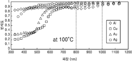
도 9a 및 도 9b는 알루미늄(Al), 구리(Cu), 은(Ag), 금(Au)이 레이저 빔의 파장에 따른 반사도를 나타낸 것으로써, 도 9a는 상온(25℃)에서의 반사도를 측정한 것이며, 도 9b는 100℃에서의 반사도를 측정한 것이다.
도 10은 다른 실시예에 따른 레이저 헤드를 나타낸 사시도이다. 1A and 1B are a perspective view and a cross-sectional view schematically showing an object to be welded by a laser welding apparatus according to an embodiment.
Fig. 2 is a view showing an example of the diaphragm of Fig. 1a.
3 is a view showing a laser welding apparatus according to an embodiment,
4A and 4B are views showing an example of an optical fiber block in the optical connector of FIG.
5 is a view showing a receiving space according to another embodiment.
6 is a diagram conceptually showing a state in which a laser beam is irradiated on an object to be processed.
7A and 7B show the beam profile of the laser beam irradiated by the laser welding apparatus according to the embodiment. Fig. 7A shows the beam profile of the laser L at the focal length of the focusing
FIG. 8 conceptually shows a process in which a laser beam irradiated to an object in a laser head is reflected and incident into the laser head.
9A and 9B show the reflectivity of aluminum (Al), copper (Cu), silver (Ag) and gold (Au) according to the wavelength of the laser beam. FIG. 9A shows the reflectivity at room temperature And FIG. 9B shows the reflectance at 100 ° C.
10 is a perspective view showing a laser head according to another embodiment.
이하, 첨부된 도면을 참조하여 본 발명의 실시예를 상세히 설명한다. 도면에서 동일한 참조부호는 동일한 구성요소를 지칭하며, 각 구성요소의 크기나 두께는 설명의 명료성을 위하여 과장되어 있을 수 있다. Hereinafter, embodiments of the present invention will be described in detail with reference to the accompanying drawings. In the drawings, like reference numerals refer to like elements, and the size and thickness of each element may be exaggerated for clarity of explanation.
“제1”, “제2” 등과 같이 서수를 포함하는 용어는 다양한 구성 요소들을 설명하는데 사용될 수 있지만, 구성 요소들은 용어들에 의해 한정되지는 않는다. 용어들은 하나의 구성요소를 다른 구성요소로부터 구별하는 목적으로만 사용된다. 예를 들어, 본 발명의 권리 범위를 벗어나지 않으면서 제1 구성요소는 제2 구성요소로 명명될 수 있고, 유사하게 제2 구성요소도 제1 구성요소로 명명될 수 있다. “및/또는” 이라는 용어는 복수의 관련된 항목들의 조합 또는 복수의 관련된 항목들 중의 어느 하나의 항목을 포함한다. Terms including ordinals such as " first, " " second, " and the like can be used to describe various elements, but the elements are not limited by terms. Terms are used only for the purpose of distinguishing one component from another. For example, without departing from the scope of the present invention, the first component may be referred to as a second component, and similarly, the second component may also be referred to as a first component. The term " and / or " includes any combination of a plurality of related items or any of a plurality of related items.
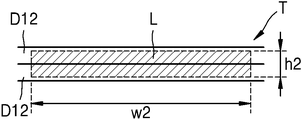
도 1a 및 도 1b는 실시예에 따른 레이저 용접 장치에 의해 용접되는 가공 대상물(T)을 개략적으로 나타낸 사시도 및 단면도이다. 도 2는 도 1a의 다이어프램(D)의 일 예를 나타낸 도면이다.Figs. 1A and 1B are a perspective view and a cross-sectional view schematically showing a workpiece T to be welded by a laser welding apparatus according to an embodiment. Fig. 2 is a view showing an example of the diaphragm D of Fig. 1a.
도 1a, 도 1b 및 도 2를 참조하면, 가공 대상물(T)은 신축성 있는 파이프 형태를 가지는 금속 벨로우즈(bellows)일 수 있다. 금속 벨로우즈는 밸브, 자동차 부품, 반도체 진공 장비 등 다양한 장치 또는 기계의 부품으로 사용될 수 있다.1A, 1B and 2, the object to be processed T may be a metal bellows having a stretchable pipe shape. Metal bellows can be used as a part of various devices or machines, such as valves, automotive parts, semiconductor vacuum equipment.
가공 대상물(T)은 복수 개의 다이어프램(D)을 상하 방향으로 중첩하도록 배치하고 이들을 연결하여 여러 개의 파형(convolution)을 갖는 유연한 쉘(flexible shell) 구조를 가질 수 있다. 다이어프램(D)은 금속 재질의 링 형상을 가지며, 내경에 대응하는 내측 테두리(D11)와 외경에 대응하는 외측 테두리(D12)를 가진다. 다이어프램(D)의 두께(t)는 2 mm 이하, 보다 바람직하게는, 0.1 mm 이하일 수 있다. The object to be processed T may have a flexible shell structure in which a plurality of diaphragms D are arranged so as to overlap each other in the vertical direction and are connected to each other to have a plurality of convolutions. The diaphragm D has a metal ring shape and has an inner frame D11 corresponding to the inner diameter and an outer frame D12 corresponding to the outer diameter. The thickness t of the diaphragm D may be 2 mm or less, more preferably 0.1 mm or less.
이러한 가공 대상물(T)을 제작하기 위하여, 인접한 다이어프램들(D)의 연결 부위에 레이저 빔(L)을 조사함으로써, 인접한 다이어프램들(D)을 레이저 용접에 의해 연결할 수 있다. 예를 들어, 인접한 다이어프램들(D)의 내측 테두리들(D11)을 레이저 용접하여 파형의 단위 셀을 만든 후, 다시 이러한 단위 셀들을 중첩시켜 단위 셀들의 다이어프램(D)의 외측 테두리들(D12)을 용접하여, 가공 대상물(T)을 제작할 수 있다. In order to manufacture such a workpiece T, the adjacent diaphragms D can be connected by laser welding by irradiating the laser beam L to the connecting portion of the adjacent diaphragms D. [ For example, the inner edges D11 of the adjacent diaphragms D are laser welded to form a unit cell of a waveform, and then the unit cells are superimposed to form outer edges D12 of the diaphragm D of the unit cells. The object to be processed T can be manufactured.
상기와 같이, 가공 대상물(T)에 대한 용접이 복수의 다이어프램들(D)의 내측 테두리들(D11) 또는 외측 테두리들(D12)에 대해 이루어지기 때문에, 용접이 필요한 용접 부위는 매우 얇을 수 있다. 예를 들어, 용접 부위의 두께는 0.1 mm 이하일 수 있다. As described above, since the welding to the object T is performed with respect to the inner rim D11 or the outer rim D12 of the plurality of diaphragms D, the welding portion requiring welding may be very thin . For example, the thickness of the welded portion may be 0.1 mm or less.
이러한 두께가 매우 얇은 용접 부위에 일반적인 레이저 빔을 조사하여 용접을 진행할 경우, 용접 부위에 레이저 빔의 단위 면적당 에너지 밀도가 집중되어 가공물이 손상되는 등 용접 품질이 나빠져 가공성이 저하될 수 있으며, 가공 중 발생할 수 있는 연기나 그을음 등을 세척 하는 공정이 필요해서 생산성 역시 저하되는 현상이 발생할 수 있다.When welding is performed by irradiating a general laser beam to such a very thin welding spot, the energy density per unit area of the laser beam is concentrated at the welding spot, thereby damaging the workpiece, resulting in deteriorated welding quality. It is necessary to clean the smoke or soot which may be generated, and the productivity may be lowered.
실시예에 따른 레이저 용접 장치(1)는, 상기와 같이 용접 부위가 매우 얇은 경우에도, 가공성 및 생산성을 향상시키기 위하여, 용접 부위를 확장해서 단위 면적당 에너지 밀도를 분산시킬 수 있는 구조를 제공한다.The
도 3은 실시예에 따른 레이저 용접 장치(1)를 나타낸 도면이며, 도 4a 및 도4b는 도 3의 광 커넥터(21) 내의 광섬유 블록(211)의 일 예를 나타낸 도면이다. Fig. 3 is a view showing a
도 3을 참조하면, 실시예에 따른 레이저 용접 장치(1)는 복수의 레이저 다이오드(10)와, 복수의 레이저 다이오드(10)에서 나오는 레이저 빔을 전송하는 복수의 전송용 광섬유(20)와, 복수의 전송용 광섬유(20) 각각의 일 단부를 정렬하는 광섬유 블록(211)을 포함하는 광 커넥터(21), 광 커넥터(21)를 통해 나오는 레이저 빔을 가공물에 조사시킬 수 있는 레이저 헤드(30)를 포함할 수 있다. 3, the
복수의 레이저 다이오드(10) 각각은 소정 파장의 레이저 빔을 발생시킬 수 있다. 복수의 레이저 다이오드(10)는 필요에 따라 서로 유사한 파장의 레이저 빔을 발생시키거나 다른 파장의 레이저 빔을 발생시킬 수 있다. 예를 들어, 복수의 레이저 다이오드(10)는 800 nm ~ 1000 nm의 파장을 가지는 레이저 빔을 발생시킬 수 있다. 여기서, 파장이 유사하다는 의미는 동일하거나, 동일하지 않더라도 그 차이가 10 nm 이내인 것을 의미하며, 파장이 다르다는 의미는 그 차이가 10 nm를 초과한 것을 의미할 수 있다.Each of the plurality of
복수의 레이저 다이오드(10)의 출력은 1 W ~ 10 kW일 수 있고 필요에 따라서 각각의 레이저 다이오드 출력이 유사하거나 다를 수 있다. 여기서, 출력이 유사하다는 의미는 동일하거나, 동일하지 않더라도 그 차이가 10 W 이내인 것을 의미하며, 출력이 다르다는 의미는 그 차이가 10 W를 초과한 것을 의미할 수 있다.The output of the plurality of
복수의 전송용 광섬유(20)는 복수의 레이저 다이오드(10)에 연결되며, 복수의 레이저 다이오드(10)에서 발생한 레이저 빔을 광 커넥터(21)를 통해 레이저 헤드(30)로 전송할 수 있다. 복수의 전송용 광섬유(20)의 개수는 복수의 레이저 다이오드(10)의 개수와 동일하다. A plurality of transmission
복수의 전송용 광섬유(20)의 일 단부의 표면(201, 이하 '단면(201)' 이라 한다)은 무반사 코팅될 수 있다. 그에 따라, 복수의 전송용 광섬유(20)를 통해 전송된 레이저 빔이 전송용 광섬유(20)의 일 단부에서 반사되어 레이저 다이오드 방향으로 되돌아가는 것을 방지할 수 있다.The surface 201 (hereinafter referred to as "
레이저 헤드(30)는 광 커넥터(21)에 의해 복수의 전송용 광섬유(20)와 연결되며, 복수의 전송용 광섬유(20)에 의해 전송된 레이저 빔을 가공 대상물(T)에 조사한다.The
광 커넥터는(21)는 복수의 전송용 광섬유(20)가 소정 형태로 배열되도록 지지하는 광섬유 블록(211)을 레이저 헤드(30)와 연결할 수 있게 하는 커넥터 기구부(212)로 구성된다. 레이저 헤드(30)는 복수의 전송용 광섬유(20)에 의해 전송된 레이저 빔을 집광하여 가공 대상물(T)에 조사하는 광학계(33)를 포함한다.The
도 4a 및 도 4b를 참조하면, 광섬유 블록(211)은 복수의 전송용 광섬유(20)를 수용하는 수용 공간(S)을 가질 수 있다. 광섬유 블록(211)은 수용 공간(S)을 형성하는 내부 블록(220)과, 내부 블록(220)을 둘러싸는 외부 블록(230) 을 포함할 수 있다. 내부 블록(220)은 상부 블록(221)과 하부 블록(222)을 포함할 수 있다.Referring to FIGS. 4A and 4B, the
상부 블록(221) 및 하부 블록(222) 중 적어도 하나에 수용 공간(S)을 형성하기 위한 수용 홈(221g)이 형성될 수 있다. 예를 들어, 상부 블록(221)에 수용 공간(S)을 형성하기 위한 수용 홈(221g)이 형성될 수 있다.A receiving groove 221g for forming a receiving space S may be formed in at least one of the
수용 공간(S)에 배치된 전송용 광섬유(20)의 단면(201)은 내부 블록(220)보다 1mm 정도 앞으로 나오도록 배치될 수 있다. 각각의 전송용 광섬유의 단면(201)은 내부 블럭(220)과 유사한 거리로 떨어져서 배치될 수 있다. 여기서, 유사하다는 의미는 동일하거나, 동일하지 않더라도 그 차이가 1% 이내일 수 있다.The
수용 공간(S)의 형상에 따라, 수용 공간(S)에 배열된 복수의 전송용 광섬유(20)의 배치는 달라질 수 있다. 예를 들어, 수용 공간(S)은 수평 방향(또는 제1 방향)으로 폭(w1)이 수직 방향(또는 제2 방향)으로의 높이(h1)보다 클 수 있다. 예를 들어, 수용 공간(S)의 수평 방향으로의 폭(w1)은 수직 방향으로의 높이(h1)보다 3배 이상, 보다 바람직하게는 5배 이상 클 수 있다. Depending on the shape of the accommodation space S, the arrangement of the plurality of transmission
이와 같이 수용 공간(S)이 수평 방향으로의 폭(w1)이 수직 방향으로의 높이(h1)보다 크기 때문에, 이러한 수용 공간(S)에 배치된 복수의 전송용 광섬유(20)는 수평 방향으로 배치될 수 있다. 복수의 전송용 광섬유(20)는 적어도 하나의 행과 복수의 열을 가지도록 배치될 있다. 예를 들어, 5개의 전송용 광섬유(20)는 1 행과 5열을 가지도록 배치될 수 있다. 다만, 복수의 전송용 광섬유(20)의 배열은 이에 한정되지 아니하며, 복수의 전송용 광섬유(20)의 직경, 개수 및 수용 공간(S)의 형태에 따라 달라질 수 있다. 예를 들어, 복수의 전송용 광섬유(20)는 도 5와 같이 두 줄로 배열되거나, 그 이상으로 배열될 수 있다.Since the width w1 of the accommodating space S in the horizontal direction is larger than the height h1 in the vertical direction as described above, the plurality of transmission
수용 공간(S)은, 그 내부에 삽입된 복수의 전송용 광섬유(20)들을 지지하도록, 복수의 전송용 광섬유(20)들의 높이 또는 폭의 합에 대응하는 높이 또 폭을 가질 수 있다. 예를 들어, 수용 공간(S)의 내부에 5개의 전송용 광섬유들(20)이 수용되는 경우, 수용 공간(S)의 높이(h1)는 하나의 전송용 광섬유(20)의 높이와 유사하며, 수용 공간(S)의 폭(w1)은 전송용 광섬유(20) 5개의 폭의 합과 유사할 수 있다. 여기서, 유사하다는 의미는 동일하거나, 동일하지 않더라도 그 차이가 10% 이하일 수 있다. 다시 말하면, 수용 공간(S)의 높이(h1)는 전송용 광섬유(20)의 외경과 동일하거나 크더라도 그 차이가 10% 이하일 수 있으며, 수용 공간(S)의 폭(w1)은 폭 방향으로 배열된 복수의 전송용 광섬유(20)의 외경의 합과 동일하거나 크더라도 그 차이가 10% 이하일 수 있다.The accommodation space S may have a height or a width corresponding to the sum of the heights or the widths of the plurality of transmission
다시 도 3을 참조하면, 광학계(33)는 이러한 수용 공간(S)에 수용된 복수의 전송용 광섬유 단면(201)들의 전방에 배치된다. 광학계(33)는 평행화 렌즈(331)와 포커싱 렌즈(332)를 포함한다. Referring again to FIG. 3, the
복수의 전송용 광섬유(20)에 의해 전송된 레이저 빔은 평행화 렌즈(331)와 포커싱 렌즈(332)를 거쳐 가공 대상물(T)에 조사된다. 상술한 것처럼, 복수의 전송용 광섬유(20)는 광섬유 블록(21)의 수용 공간(S)에 의해 수평 방향으로 배열된 상태이기 때문에, 가공 대상물(T)과 포커싱 렌즈(332)의 떨어진 거리가 포커싱 렌즈(332)의 초점 거리인 경우에는 전송된 각각의 전송용 광섬유 단면(201)의 레이저 빔이 각각 집속되어 조사되고, 가공 대상물(T)과 포커싱 렌즈(332)의 떨어진 거리가 초점 거리를 벗어난 경우에는 각각의 레이저 빔은 초점을 이탈되어 서로 겹쳐지게 되어서 라인 빔 형상을 가질 수 있다. 예를 들어, 가공 대상물(T)에 조사된 라인 빔 형상의 레이저 빔(L)은 수직 방향으로의 높이(h2)는 소정의 높이, 예를 들어, 0.5 mm 이하의 높이를 가지며, 수평 방향으로의 폭(w2)은 수직 방향으로의 높이(h2)보다 길게 연장된 형상을 가질 수 있다.The laser beam transmitted by the plurality of transmission
가공 대상물(T)과 포커싱 렌즈(332)의 떨어진 거리는, 가공 대상물(T)과 레이저 헤드(30) 중 적어도 하나를 이동시킴에 따라, 조절될 수 있다. 예를 들어, 레이저 헤드(30)를 이동시켜, 가공 대상물(T)과 포커싱 렌즈(332)의 떨어진 거리를 조절할 수 있다.The distance between the object to be processed T and the focusing
도 6은 가공 대상물(T)에 레이저 빔(L)이 조사된 상태를 개념적으로 나타낸 도면이다. 도 6을 참조하면, 가공 대상물(T)에 조사된 레이저 빔(L)은 수직 방향으로의 높이(h2)에 비해 수평 방향으로의 폭(w2)이 크다. 6 is a diagram conceptually showing a state in which the laser beam L is irradiated on the object to be processed T. Fig. Referring to Fig. 6, the width w2 of the laser beam L irradiated on the object T in the horizontal direction is larger than the height h2 in the vertical direction.
이러한 라인 형상의 레이저 빔(L)은, 원형의 레이저 빔에 비해, 수평 방향으로 레이저 빔(L)의 조사 범위가 확장되기 때문에, 두께가 얇은 용접 부위를 신속하게 용접할 수 있다. Since such a line-shaped laser beam L expands the irradiation range of the laser beam L in the horizontal direction as compared with the circular laser beam, it is possible to quickly weld a thin welded portion.
도 7a 및 도 7b는 실시예에 따른 레이저 용접 장치(1)에서 조사되는 레이저 빔(L)의 빔 프로파일을 나타낸 것으로써, 도 7a는 포커싱 렌즈(332)의 초점 거리에서의 레이저(L)의 빔 프로파일을 나타내고, 도 7b는 포커싱 렌즈(332)의 초점 거리에서 벗어난 지점의 레이저(L)의 빔 프로파일을 나타낸다.7A and 7B show the beam profile of the laser beam L irradiated from the
도 7a를 참조하면, 가공 대상물(T)과 포커싱 렌즈(332)의 떨어진 거리가 포커싱 렌즈(332)의 초점 거리일 경우에는, 모든 전송용 광섬유(20)에서 나오는 레이저 빔(L)이 가공 대상물(T)에 각각 초점을 맺히기 때문에 가공 대상물(T)에 조사된 레이저 빔(L)은 각 레이저 다이오드(10)별로 에너지 밀도 차이가 구분된다. 반면, 도 7b를 참조하면, 가공 대상물(T)과 포커싱 렌즈(332)의 떨어진 거리가 초점 거리보다 짧거나 긴 경우에는, 가공 대상물(T)에 조사된 레이저 빔(L)의 에너지 밀도가 균일하게 나타냄을 확인할 수 있었다. 가공 대상물(T)의 위치는 가공 대상물(T)의 재질, 형상 등에 의해서 가공되는 정도로 결정되어지며, 바람직하게는 포커싱 렌즈(332)의 초점 거리의 ±10% 이내에서 결정된다. 7A, when the distance between the object to be processed T and the focusing
또한, 다시 도 3을 참조하면, 실시예에 따른 레이저 용접 장치(1)에서는, 가공 대상물(T)에 조사되는 레이저 빔(L)이 레이저 다이오드(10)에서 발생한 레이저 빔이 전송용 광섬유(20)에 의해 전달되는 구조이다. 실시예에 따른 레이저 용접 장치(1)에서는, 광섬유 레이저를 이용하는 방식과 같이 별도의 광 펌핑을 위한 액티브 광섬유를 포함하지 않기 때문에 가공 대상물(T)에 조사되는 레이저 빔(L)의 파장은 레이저 다이오드(10)에서 발생한 레이저 빔의 파장과 동일하다. 예를 들어, 레이저 다이오드(10)에서 발생한 레이저 빔의 파장이 800 nm ~ 1000 nm일 경우, 가공 대상물(T)에 조사되는 레이저 빔(L)의 파장 역시 800 nm ~ 1000 nm일 수 있다. 3, in the
또한, 실시예에 따른 레이저 용접 장치(1)에서는, 광섬유 레이저와 같이 별도의 광 펌핑을 위한 액티브 광섬유를 포함하지 않기 때문에, 광섬유 레이저를 이용한 방식에 비해, 동일 출력에서 가공 대상물(T)에 조사되는 레이저 빔의 에너지 밀도가 상대적으로 작을 수 있다.In addition, since the
이와 같이, 가공 대상물(T)에 조사되는 레이저 빔(L)의 단위 면적당 에너지 밀도를 낮춤으로써, 가공 대상물(T)의 용접 부위의 온도가 급격하게 상승하는 것을 방지하고, 그에 따라 용접 부위가 시커멓게 그을리는 현상을 방지할 수 있다. 그리하여, 가공 대상물(T)의 용접 품질을 향상시킬 수 있다.By thus lowering the energy density per unit area of the laser beam L irradiated on the object to be processed T, the temperature of the welding spot of the object T is prevented from rising sharply, It is possible to prevent the phenomenon of cutting. Thus, the welding quality of the object to be processed T can be improved.
각각의 레이저 다이오드의 파장은 필요에 따라 동일한 파장으로 구성하거나 달리 구성해서 가공 대상물(T)에 조사할 수 있다.The wavelengths of the respective laser diodes can be constituted by the same wavelength as necessary or can be irradiated onto the object to be processed T otherwise.
한편, 레이저 용접 장치(1)는 가공 대상물(T)이 탑재되는 작업 테이블(40)과, 가공 대상물(T)의 용접 부위를 촬영하는 비전 카메라(50)와, 용접 부위를 표시하는 디스플레이부(60)를 더 포함할 수 있다.On the other hand, the
작업 테이블(40)은 회전 가능할 수 있다. 그에 따라, 레이저 헤드(30)에 의해 조사된 레이저 빔(L)이 가공 대상물(T)의 외부 테두리(D12) 또는 내부 테두리(D11)에 연속적으로 조사될 수 있다. The work table 40 may be rotatable. The laser beam L irradiated by the
비전 카메라(50)는 레이저 헤드(30)에 배치되며, 디스플레이부(60)는 비전 카메라(50)에 연결될 수 있다. 그에 따라, 작업자는 디스플레이부(60)를 통해 표시된 정보에 기초하여, 가공 대상물(T)의 용접 부위에 대한 용접이 제대로 이루어지고 있는지 모니터링할 수 있다.The
레이저 용접 장치(1)는 산화 방지 노즐(70)을 더 포함할 수 있다. 산화 방지 노즐(70)은 용접 부위에 불활성 기체를 분사할 수 있다. 불활성 기체는 질소 가스 등일 수 있다. 이러한 산화 방지 노즐(70)을 통해, 용접 부위의 산화를 방지할 수 있다.The
한편, 금속 벨로우즈와 같은 용접 부위가 얇은 가공 대상물(T)에 레이저 빔(L)을 조사하는 과정에서, 가공 대상물(T)에 의해 레이저 빔(L)이 반사되거나 산란되는 현상이 발생할 수 있다.On the other hand, the laser beam L may be reflected or scattered by the object T in the process of irradiating the laser beam L onto the object T having a thin welding portion such as a metal bellows.
도 8은 레이저 헤드(30)에서 가공 대상물(T)에 조사된 레이저 빔이 반사되어 레이저 헤드(30) 내부로 재입사되는 과정을 개념적으로 나타낸다. 도 8을 참조하면, 레이저 헤드(30)에서는 전송용 광섬유(20)에 의해 전송된 레이저 빔이 평행화 렌즈(331) 및 포커싱 렌즈(332)를 거쳐 가공 대상물(T)로 조사된다. 조사된 레이저 빔(L)의 일부는 가공 대상물(T)에 흡수되어 용접에 이용되지만, 다른 일부는 가공 대상물(T)에 의해 반사 또는 산란될 수 있다. 가공 대상물(T)에 의해 반사 또는 산란된 레이저 빔(RL)은 레이저 헤드(30)의 내부로 입사될 수 있다. 레이저 헤드(30)의 내부로 입사된 레이저 빔(RL)은 포커싱 렌즈(332) 및 평행화 렌즈(331)를 거쳐 광섬유 블록(31)으로 전달될 수 있다. 8 conceptually shows a process in which the laser beam irradiated on the object T in the
레이저 헤드(30)의 내부로 입사된 레이저 빔(RL)이 광섬유 블록(31)에 흡수될 경우 광섬유 블록(31)이 가열될 수 있으며, 심할 경우 수용 공간(S)에 수용된 전송용 광섬유(20)의 손상이 발생할 수 있다.The
이러한 점을 고려하여, 실시예에 따른 레이저 용접 장치(1)에서는, 레이저 헤드(30)의 내부로 레이저 빔(RL)이 입사되더라도, 레이저 헤드(30) 내부에 배치된 전송용 광섬유(20)의 손상을 방지할 수 있는 구조를 제공할 수 있다. In consideration of this point, in the
다시 도 4a를 참조하면 광섬유 블록(220)의 재질을 알루미늄(Al), 구리(Cu), 은(Ag), 금(Au)으로 구성하면, 반사된 레이저 빔(RL)에 대한 반사도를 높일 수 있다. 이러한 재질로 구성된 광섬유 블록(220)은 가공 대상물(T)에서 반사되어 레이저 헤드(30)의 광학계(33)를 통해 광섬유 블록(220)으로 되돌아오는 레이저 빔(RL)에 대한 반사도가 80% 이상일 수 있다. 그에 따라, 광섬유 블록(31a)이 레이저 헤드(30a)의 내부로 입사된 레이저 빔(RL)에 의해 가열되는 것을 방지할 수 있다.4A, if the
도 9a 및 도 9b는 알루미늄(Al), 구리(Cu), 은(Ag), 금(Au)이 레이저 빔의 파장에 따른 반사도를 나타낸 것으로써, 도 9a는 상온(25℃)에서의 반사도를 측정한 것이며, 도 9b는 100℃에서의 반사도를 측정한 것이다.9A and 9B show the reflectivity of aluminum (Al), copper (Cu), silver (Ag) and gold (Au) according to the wavelength of the laser beam. FIG. 9A shows the reflectivity at room temperature And FIG. 9B shows the reflectance at 100 ° C.
도 9a 및 도 9b를 참조하면, 알루미늄(Al), 구리(Cu), 은(Ag) 또는 금(Au)은, 소정의 온도 범위, 예를 들어, 25℃ ~ 100 ℃에서 파장 800 nm ~ 1000 nm의 레이저 빔에 대한 반사도가 80% 이상으로 나타남을 알 수 있다.9A and 9B, aluminum (Al), copper (Cu), silver (Ag) or gold (Au) is irradiated at a predetermined temperature range, for example, nm reflectance of the laser beam is more than 80%.
이러한 점을 고려하여, 광섬유 블록(220)의 재질은 알루미늄(Al), 구리(Cu), 은(Ag), 금(Au) 중 적어도 하나를 포함할 수 있다. 그에 따라, 레이저 헤드(30)의 내부로 입사된 레이저 빔(RL)의 파장이 800 nm ~ 1000 nm인 경우, 광섬유 블록(30)에 입사된 레이저 빔(RL)을 80% 이상 반사시킬 수 있다. 그에 따라, 광섬유 블록(220)이 레이저 헤드(30)의 내부로 입사된 레이저 빔(RL)에 의해 가열되는 것을 방지할 수 있다.In consideration of this point, the material of the
한편, 광섬유 블록(220)은 열전도도가 200 W/mK ~ 430 W/mK 일 수 있다. 예를 들어, 광섬유 블록(220)의 재질은 알루미늄(Al), 구리(Cu), 은(Ag), 금(Au) 중 적어도 하나를 포함할 수 있다. Meanwhile, the
이와 같이, 광섬유 블록(220)은 열전도도가 우수하고 레이저 빔에 대한 반사가 우수한 재질을 선택함으로써, 전송용 광섬유(20)에서 발생된 열이 외부로 용이하게 방출되면서도, 레이저 헤드(30)로 입사된 레이저 빔(RL)에 의해 가열되는 것을 방지할 수 있다.As described above, the
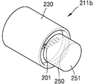
도 10은 다른 실시예에 따른 광섬유 블록(30b)를 나타낸 사시도이다. 도 10을 참조하면, 광섬유 블록(30b)은 전송용 광섬유(20)의 단면(201)과 석영 블록(250)을 융착 접합해서 붙인 구조를 더 포함할 수 있다. 석영 블록(250)의 지름은 광섬유 수용 공간(S)의 폭(w1)과 동일하거나 그보다 클 수 있고, 두께는 석영 블록(25)과 융착 접합 된 전송용 광섬유(20)의 단면(201)에서의 레이저 발산각을 고려해서 석영 블록(25)의 단면(251)에 레이저 빔(L)이 지나갈 수 있도록 고려해서 결정된다. 이 경우, 광섬유 단면(201)에는 무반사 코팅을 하지 않고, 석영 블록(25)의 단면(251)에 무반사 코팅을 한다. 석영 블록(25)의 단면(251)을 투과하는 레이저 빔은 전송용 광섬유(20)의 단면(201)을 투과하는 레이저 빔보다 크기 때문에 먼지 및 외부 충격에 대한 영향이 작아지며, 레이저 빔의 단위면적 당 에너지 밀도가 낮아지기 때문에 레이저 빔에 의한 코팅 손상을 최소화 시킬 수 있다. 또한, 전송용 광섬유(20)를 둘러싸는 수냉식 구조(미도시)의 단부를 석영 블록(250)에 의해 밀폐할 수 있기 때문에, 레이저 헤드(30)의 내부로 입사된 빔(RL)에 의해서 발생한 열을 수냉으로 식힐 수 있어서 전송용 광섬유 (20)의 손상을 방지할 수 있다. 10 is a perspective view showing an optical fiber block 30b according to another embodiment. 10, the optical fiber block 30b may further include a structure in which the
한편, 상술한 실시예에서는, 도면을 기준으로 수평 방향, 수직 방향을 구분하였으나, 레이저 용접 장치(1) 및 가공 대상물(T)의 배치에 따라 수평 방향 및 수직 방향이 서로 바뀔 수 있음은 물론이다.Although the horizontal direction and the vertical direction are defined on the basis of the drawings in the above embodiment, it is needless to say that the horizontal direction and the vertical direction may be changed depending on the arrangement of the
이상에서 본 발명의 실시예가 설명되었으나, 이는 예시적인 것에 불과하며, 당해 분야에서 통상적 지식을 가진 자라면 이로부터 다양한 변형 및 균등한 타 실시예가 가능하다는 점을 이해할 것이다. While the invention has been shown and described with reference to certain preferred embodiments thereof, it will be understood by those skilled in the art that various changes and modifications may be made without departing from the scope of the invention as defined by the appended claims.
1 : 레이저 용접 장치
10 : 레이저 다이오드
20 : 전송용 광섬유
21 : 커넥터
211 :
광섬유 블록
212 : 커넥터 기구부
220 : 내부 블록
221 : 상부 블록
221g: 수용 홈
222 : 하부 블록
230 : 외부 블록
250 : 석영 블록
251 : 석영 블록 단면
30 : 레이저 헤드
33 : 광학계
331 : 평행화 렌즈
332 : 포커싱 렌즈
40 : 작업 테이블
50 : 비전 카메라
60 : 디스플레이부
70 : 산화 방지 노즐
T : 가공 대상물
D : 다이어프램
D11 : 내측 테두리
D12 : 외측 테두리
S : 수용 공간1: laser welding device 10: laser diode
20: Optical fiber for transmission 21: Connector
211: Optical fiber block 212: Connector mechanism
220: inner block 221: upper block
221g: receiving groove 222: bottom block
230: outer block 250: quartz block
251: quartz block cross section 30: laser head
33: Optical system 331: Parallelizing lens
332: focusing lens 40: work table
50: vision camera 60: display unit
70: anti-oxidation nozzle T: object to be processed
D: Diaphragm D11: Inner rim
D12: outer frame S: accommodation space
Claims (20)
상기 복수의 레이저 다이오드에 연결되며, 상기 복수의 레이저 다이오드에서 발생된 레이저 빔을 전송하는 복수의 전송용 광섬유;
레이저 빔을 가공 대상물에 조사하는 레이저 헤드; 및
상기 복수의 전송용 광섬유을 상기 레이저 헤드에 연결하며, 상기 복수의 전송용 광섬유에 의해 전송된 레이저 빔을 상기 레이저 헤드에 보내는 광 커넥터;를 포함하며,
상기 광 커넥터는 상기 복수의 전송용 광섬유 각각의 일 단부가 제 1방향을 따라 배치되도록, 상기 복수의 전송용 광섬유를 수용하는 수용 공간을 가지는 광섬유 블록;을 포함하며
상기 레이저 헤드는 상기 광 커넥터에서 전송되는 레이저 빔을 가공 대상물에 조사하는 광학계를 포함하는, 레이저 용접 장치.A plurality of laser diodes;
A plurality of transmission optical fibers connected to the plurality of laser diodes and transmitting a laser beam generated from the plurality of laser diodes;
A laser head for irradiating a laser beam onto an object to be processed; And
And an optical connector for connecting the plurality of transmission optical fibers to the laser head and for transmitting a laser beam transmitted by the plurality of transmission optical fibers to the laser head,
And the optical connector includes an optical fiber block having an accommodation space for accommodating the plurality of transmission optical fibers so that one end of each of the plurality of transmission optical fibers is disposed along a first direction
Wherein the laser head includes an optical system for irradiating the object to be processed with the laser beam transmitted from the optical connector.
상기 수용 공간의 형상은, 상기 제1 방향으로의 폭이 상기 제1 방향과 수직인 제2 방향으로의 높이보다 큰, 레이저 용접 장치.The method according to claim 1,
Wherein the shape of the accommodating space is larger than a height in a second direction in which the width in the first direction is perpendicular to the first direction.
상기 복수의 전송용 광섬유의 상기 일 단부의 표면은 무반사 코팅된, 레이저 용접 장치.The method according to claim 1,
Wherein the surface of said one end of said plurality of transmission optical fibers is anti-reflective coating.
상기 복수의 전송용 광섬유의 상기 일 단부의 표면의 반사율은 1% 이하인, 레이저 용접 장치.The method of claim 3,
Wherein the reflectance of the surface of the one end of the plurality of transmission optical fibers is 1% or less.
상기 가공 대상물에 조사된 레이저 빔은 포커싱 렌즈의 초점 거리에서 각각의 레이저 빔의 초점이 맺히는, 레이저 용접 장치.The method according to claim 1,
Wherein the laser beam irradiated on the object to be processed focuses the respective laser beams at a focal length of the focusing lens.
상기 가공 대상물에 조사된 레이저 빔은 포커싱 렌즈의 초점 거리를 벗어난 지점에서 라인 빔 형상을 가지는, 레이저 용접 장치.The method according to claim 1,
Wherein the laser beam irradiated on the object has a line beam shape at a point out of the focal distance of the focusing lens.
상기 가공 대상물에 조사된 레이저 빔의 파장은, 상기 레이저 다이오드에서 발생된 레이저 빔의 파장과 동일한, 레이저 용접 장치. The method according to claim 1,
Wherein the wavelength of the laser beam irradiated on the object to be processed is equal to the wavelength of the laser beam generated by the laser diode.
상기 복수의 레이저 다이오드에서 발생된 각각의 레이저 빔의 파장이 동일하거나 다른, 레이저 용접 장치.The method according to claim 1,
Wherein the wavelengths of the respective laser beams generated in the plurality of laser diodes are the same or different.
상기 레이저 다이오드의 출력은 1 W ~ 10kW 인, 레이저 용접 장치.The method according to claim 1,
Wherein an output of the laser diode is 1 W to 10 kW.
상기 복수의 레이저 다이오드에서 발생된 각각의 레이저 빔의 파워가 동일하거나 다른, 레이저 용접 장치. The method according to claim 1,
Wherein the powers of the respective laser beams generated in the plurality of laser diodes are the same or different.
상기 가공 대상물에 조사된 레이저 빔의 파장은 800 nm ~ 1000 nm인, 레이저 용접 장치.9. The method of claim 8,
Wherein a wavelength of the laser beam irradiated on the object to be processed is 800 nm to 1000 nm.
상기 수용 공간에 수용된 상기 복수의 전송용 광섬유는, 적어도 하나의 행과 복수의 열을 가지도록 배열된, 레이저 용접 장치.The method according to claim 1,
Wherein the plurality of transmission optical fibers housed in the accommodation space are arranged to have at least one row and a plurality of rows.
상기 광섬유 블록의 상기 레이저 헤드에 대향하는 표면은 레이저 빔에 대한 반사도가 80 % 이상인 물질로 구성한, 레이저 용접 장치.The method according to claim 1,
Wherein the surface of the optical fiber block facing the laser head is made of a material having a reflectance of 80% or more with respect to the laser beam.
상기 광섬유 블록은 열 전도도가 200 W/mK ~ 430 W/mK 인, 레이저 용접 장치.The method according to claim 1,
Wherein the optical fiber block has a thermal conductivity of 200 W / mK to 430 W / mK.
상기 광섬유 블록의 재질은, 알루미늄(Al), 구리(Cu), 은(Ag), 금(Au) 중 적어도 하나를 포함하는, 레이저 용접 장치.The method according to claim 13 or 14,
Wherein the material of the optical fiber block includes at least one of aluminum (Al), copper (Cu), silver (Ag), and gold (Au).
상기 광 커넥터는,
상기 복수의 전송용 광섬유의 상기 일 단부에 융착 접합된 석영 블록을 더 포함하는, 레이저 용접 장치.The method according to claim 1,
The optical connector includes:
And a quartz block fused and bonded to the one end of the plurality of transmission optical fibers.
상기 석영 블록의 상기 레이저 헤드에 대향하는 표면은 무반사 코팅된, 레이저 용접 장치.17. The method of claim 16,
Wherein the surface of the quartz block facing the laser head is anti-reflective coating.
상기 복수의 레이저 다이오드에 연결되며, 상기 복수의 레이저 다이오드에서 발생된 레이저 빔을 전송하는 복수의 전송용 광섬유;
레이저 빔을 가공 대상물에 조사하는 레이저 헤드; 및
상기 복수의 전송용 광섬유에 연결되며, 상기 복수의 전송용 광섬유에 의해 전송된 레이저 빔을 레이저 헤드로 보내는 광 커넥터;를 포함하며,
상기 광 커넥터는, 상기 복수의 전송용 광섬유를 수용하는 수용 공간을 가지는 광섬유 블록을 포함하며,
상기 레이저 헤드는 상기 복수의 광섬유 블록의 전방에 배치되며, 상기 복수의 전송용 광섬유에 의해 전송된 레이저 빔을 상기 가공 대상물로 조사하는 광학계를 포함하며,
상기 광섬유 블록의 상기 레이저 헤드에 대향하는 표면은, 레이저 빔에 대한 반사도가 80% 이상인, 레이저 용접 장치.A plurality of laser diodes;
A plurality of transmission optical fibers connected to the plurality of laser diodes and transmitting a laser beam generated from the plurality of laser diodes;
A laser head for irradiating a laser beam onto an object to be processed; And
And an optical connector connected to the plurality of transmission optical fibers for transmitting the laser beam transmitted by the plurality of transmission optical fibers to the laser head,
Wherein the optical connector includes an optical fiber block having an accommodation space for accommodating the plurality of transmission optical fibers,
Wherein the laser head is disposed in front of the plurality of optical fiber blocks and includes an optical system for irradiating the object with a laser beam transmitted by the plurality of transmission optical fibers,
Wherein a surface of the optical fiber block facing the laser head has a reflectance of 80% or more with respect to the laser beam.
상기 광섬유 블록은 열 전도도가 200 W/mK ~ 430 W/mK 인, 레이저 용접 장치.19. The method of claim 18,
Wherein the optical fiber block has a thermal conductivity of 200 W / mK to 430 W / mK.
상기 광섬유 블록의 재질은, 알루미늄(Al), 구리(Cu), 은(Ag), 금(Au) 중 적어도 하나를 포함하는, 레이저 용접 장치.20. The method according to claim 18 or 19,
Wherein the material of the optical fiber block includes at least one of aluminum (Al), copper (Cu), silver (Ag), and gold (Au).
Priority Applications (2)
| Application Number | Priority Date | Filing Date | Title |
|---|---|---|---|
| KR1020160027703A KR20170104818A (en) | 2016-03-08 | 2016-03-08 | Laser welding apparatus |
| US15/357,284 US20170259372A1 (en) | 2016-03-08 | 2016-11-21 | Laser welding apparatus capable of performing bellows welding |
Applications Claiming Priority (1)
| Application Number | Priority Date | Filing Date | Title |
|---|---|---|---|
| KR1020160027703A KR20170104818A (en) | 2016-03-08 | 2016-03-08 | Laser welding apparatus |
Publications (1)
| Publication Number | Publication Date |
|---|---|
| KR20170104818A true KR20170104818A (en) | 2017-09-18 |
Family
ID=59786278
Family Applications (1)
| Application Number | Title | Priority Date | Filing Date |
|---|---|---|---|
| KR1020160027703A KR20170104818A (en) | 2016-03-08 | 2016-03-08 | Laser welding apparatus |
Country Status (2)
| Country | Link |
|---|---|
| US (1) | US20170259372A1 (en) |
| KR (1) | KR20170104818A (en) |
Cited By (1)
| Publication number | Priority date | Publication date | Assignee | Title |
|---|---|---|---|---|
| KR20200103027A (en) * | 2017-12-29 | 2020-09-01 | 코렐라스 오와이 | Laser processing apparatus and method |
Family Cites Families (7)
| Publication number | Priority date | Publication date | Assignee | Title |
|---|---|---|---|---|
| US6799897B2 (en) * | 2000-11-16 | 2004-10-05 | Shipley Company, L.L.C. | Optical connector system |
| JP3898486B2 (en) * | 2001-10-22 | 2007-03-28 | 三菱電線工業株式会社 | Laser optical connector and laser guide |
| MXPA05005658A (en) * | 2002-12-02 | 2005-08-16 | 3M Innovative Properties Co | Illumination system using a plurality of light sources. |
| US7538295B2 (en) * | 2005-04-21 | 2009-05-26 | Hewlett-Packard Development Company, L.P. | Laser welding system |
| JP5499403B2 (en) * | 2010-04-20 | 2014-05-21 | 株式会社村谷機械製作所 | Laser processing apparatus and laser processing method |
| JP5931141B2 (en) * | 2014-08-26 | 2016-06-08 | ファナック株式会社 | Laser processing equipment with switchable fiber core |
| US10305252B2 (en) * | 2014-10-15 | 2019-05-28 | Lumentum Operations Llc | Laser system and method of tuning the output power of the laser system |
-
2016
- 2016-03-08 KR KR1020160027703A patent/KR20170104818A/en active Search and Examination
- 2016-11-21 US US15/357,284 patent/US20170259372A1/en not_active Abandoned
Cited By (2)
| Publication number | Priority date | Publication date | Assignee | Title |
|---|---|---|---|---|
| KR20200103027A (en) * | 2017-12-29 | 2020-09-01 | 코렐라스 오와이 | Laser processing apparatus and method |
| US11850679B2 (en) | 2017-12-29 | 2023-12-26 | Corelase Oy | Laser processing apparatus and method |
Also Published As
| Publication number | Publication date |
|---|---|
| US20170259372A1 (en) | 2017-09-14 |
Similar Documents
| Publication | Publication Date | Title |
|---|---|---|
| CN100450755C (en) | Method and device for connecting three-D shaped plastic workpiece by laser beam | |
| JP5580129B2 (en) | Solid state laser processing equipment | |
| JP3292294B2 (en) | Marking method and marking device using laser | |
| CN102481665A (en) | Laser-focusing head with ZnS lenses having a peripheral thickness of at least 5 mm and laser cutting unit and method using one such focusing head | |
| US20090071947A1 (en) | Laser beam machine | |
| KR20110098672A (en) | Method and arrangement for a firm bonding of materials | |
| JP5364039B2 (en) | Manufacturing method of resin molded products | |
| JP2008036639A (en) | Laser beam machining method and laser beam machining apparatus | |
| JP3514129B2 (en) | Laser processing equipment | |
| US10264660B2 (en) | Beam trap, beam guide device, EUV radiation generating apparatus, and method for absorbing a beam | |
| KR101455800B1 (en) | Laser diode module and optical structure for use therein | |
| JP5642493B2 (en) | Laser cutting apparatus and laser cutting method | |
| CN214768946U (en) | Three-beam wire powder mixed laser cladding system | |
| JP2019098374A (en) | Laser laminating/molding device and laser laminating method | |
| KR20210016411A (en) | Laser processing equipment for difficult-to-access workpieces | |
| KR101195602B1 (en) | Laser cutting apparatus capable of cutting workpiece having multi layer | |
| KR20170104818A (en) | Laser welding apparatus | |
| CN113102781A (en) | Three-beam wire powder mixed laser cladding system | |
| CN115846871B (en) | System and method for welding middle frame assembly of aluminum alloy mobile phone | |
| CN106425096A (en) | Laser welding device | |
| US11646228B2 (en) | Stealth dicing method including filamentation and apparatus thereof | |
| CN106536122B (en) | Laser processing system and laser processing method | |
| JP6981818B2 (en) | Laser photosynthesis device | |
| JP2020104144A (en) | Welding equipment | |
| CN110549012A (en) | Multicolor ultrashort pulse light silk recessing method and device |
Legal Events
| Date | Code | Title | Description |
|---|---|---|---|
| A201 | Request for examination | ||
| E902 | Notification of reason for refusal | ||
| AMND | Amendment | ||
| E601 | Decision to refuse application | ||
| AMND | Amendment |