KR20170104364A - Outdoor unit of air conditioner and its control method - Google Patents
Outdoor unit of air conditioner and its control method Download PDFInfo
- Publication number
- KR20170104364A KR20170104364A KR1020160175323A KR20160175323A KR20170104364A KR 20170104364 A KR20170104364 A KR 20170104364A KR 1020160175323 A KR1020160175323 A KR 1020160175323A KR 20160175323 A KR20160175323 A KR 20160175323A KR 20170104364 A KR20170104364 A KR 20170104364A
- Authority
- KR
- South Korea
- Prior art keywords
- compressor
- heat exchanger
- outdoor heat
- outdoor
- unit
- Prior art date
Links
- 238000000034 method Methods 0.000 title claims description 8
- 238000001816 cooling Methods 0.000 claims abstract description 73
- 239000007788 liquid Substances 0.000 claims abstract description 45
- 239000003507 refrigerant Substances 0.000 claims description 158
- 238000010257 thawing Methods 0.000 claims description 8
- 238000004891 communication Methods 0.000 claims description 7
- 238000007599 discharging Methods 0.000 claims description 3
- 239000003570 air Substances 0.000 description 64
- 239000003921 oil Substances 0.000 description 37
- 238000010438 heat treatment Methods 0.000 description 30
- 238000005496 tempering Methods 0.000 description 14
- 239000010725 compressor oil Substances 0.000 description 9
- 238000005057 refrigeration Methods 0.000 description 7
- 230000001276 controlling effect Effects 0.000 description 6
- 230000006837 decompression Effects 0.000 description 6
- 238000010586 diagram Methods 0.000 description 6
- 238000007664 blowing Methods 0.000 description 5
- 238000006073 displacement reaction Methods 0.000 description 5
- 239000010726 refrigerant oil Substances 0.000 description 5
- 239000000498 cooling water Substances 0.000 description 4
- 238000005461 lubrication Methods 0.000 description 4
- 238000005265 energy consumption Methods 0.000 description 3
- 230000001105 regulatory effect Effects 0.000 description 3
- 238000004378 air conditioning Methods 0.000 description 2
- 230000005494 condensation Effects 0.000 description 2
- 238000009833 condensation Methods 0.000 description 2
- 230000007423 decrease Effects 0.000 description 2
- 230000000694 effects Effects 0.000 description 2
- 239000010687 lubricating oil Substances 0.000 description 2
- 239000000155 melt Substances 0.000 description 2
- 238000004781 supercooling Methods 0.000 description 2
- 239000012080 ambient air Substances 0.000 description 1
- 239000000470 constituent Substances 0.000 description 1
- 238000010276 construction Methods 0.000 description 1
- 230000003247 decreasing effect Effects 0.000 description 1
- 230000008020 evaporation Effects 0.000 description 1
- 238000001704 evaporation Methods 0.000 description 1
- 238000002844 melting Methods 0.000 description 1
- 230000008018 melting Effects 0.000 description 1
Images


Classifications
-
- F—MECHANICAL ENGINEERING; LIGHTING; HEATING; WEAPONS; BLASTING
- F25—REFRIGERATION OR COOLING; COMBINED HEATING AND REFRIGERATION SYSTEMS; HEAT PUMP SYSTEMS; MANUFACTURE OR STORAGE OF ICE; LIQUEFACTION SOLIDIFICATION OF GASES
- F25B—REFRIGERATION MACHINES, PLANTS OR SYSTEMS; COMBINED HEATING AND REFRIGERATION SYSTEMS; HEAT PUMP SYSTEMS
- F25B49/00—Arrangement or mounting of control or safety devices
- F25B49/02—Arrangement or mounting of control or safety devices for compression type machines, plants or systems
-
- F—MECHANICAL ENGINEERING; LIGHTING; HEATING; WEAPONS; BLASTING
- F25—REFRIGERATION OR COOLING; COMBINED HEATING AND REFRIGERATION SYSTEMS; HEAT PUMP SYSTEMS; MANUFACTURE OR STORAGE OF ICE; LIQUEFACTION SOLIDIFICATION OF GASES
- F25B—REFRIGERATION MACHINES, PLANTS OR SYSTEMS; COMBINED HEATING AND REFRIGERATION SYSTEMS; HEAT PUMP SYSTEMS
- F25B1/00—Compression machines, plants or systems with non-reversible cycle
- F25B1/10—Compression machines, plants or systems with non-reversible cycle with multi-stage compression
-
- F—MECHANICAL ENGINEERING; LIGHTING; HEATING; WEAPONS; BLASTING
- F24—HEATING; RANGES; VENTILATING
- F24F—AIR-CONDITIONING; AIR-HUMIDIFICATION; VENTILATION; USE OF AIR CURRENTS FOR SCREENING
- F24F1/00—Room units for air-conditioning, e.g. separate or self-contained units or units receiving primary air from a central station
- F24F1/06—Separate outdoor units, e.g. outdoor unit to be linked to a separate room comprising a compressor and a heat exchanger
- F24F1/08—Compressors specially adapted for separate outdoor units
- F24F1/10—Arrangement or mounting thereof
-
- F—MECHANICAL ENGINEERING; LIGHTING; HEATING; WEAPONS; BLASTING
- F24—HEATING; RANGES; VENTILATING
- F24F—AIR-CONDITIONING; AIR-HUMIDIFICATION; VENTILATION; USE OF AIR CURRENTS FOR SCREENING
- F24F1/00—Room units for air-conditioning, e.g. separate or self-contained units or units receiving primary air from a central station
- F24F1/06—Separate outdoor units, e.g. outdoor unit to be linked to a separate room comprising a compressor and a heat exchanger
- F24F1/14—Heat exchangers specially adapted for separate outdoor units
- F24F1/16—Arrangement or mounting thereof
-
- F—MECHANICAL ENGINEERING; LIGHTING; HEATING; WEAPONS; BLASTING
- F25—REFRIGERATION OR COOLING; COMBINED HEATING AND REFRIGERATION SYSTEMS; HEAT PUMP SYSTEMS; MANUFACTURE OR STORAGE OF ICE; LIQUEFACTION SOLIDIFICATION OF GASES
- F25B—REFRIGERATION MACHINES, PLANTS OR SYSTEMS; COMBINED HEATING AND REFRIGERATION SYSTEMS; HEAT PUMP SYSTEMS
- F25B27/00—Machines, plants or systems, using particular sources of energy
- F25B27/02—Machines, plants or systems, using particular sources of energy using waste heat, e.g. from internal-combustion engines
-
- F—MECHANICAL ENGINEERING; LIGHTING; HEATING; WEAPONS; BLASTING
- F25—REFRIGERATION OR COOLING; COMBINED HEATING AND REFRIGERATION SYSTEMS; HEAT PUMP SYSTEMS; MANUFACTURE OR STORAGE OF ICE; LIQUEFACTION SOLIDIFICATION OF GASES
- F25B—REFRIGERATION MACHINES, PLANTS OR SYSTEMS; COMBINED HEATING AND REFRIGERATION SYSTEMS; HEAT PUMP SYSTEMS
- F25B29/00—Combined heating and refrigeration systems, e.g. operating alternately or simultaneously
- F25B29/003—Combined heating and refrigeration systems, e.g. operating alternately or simultaneously of the compression type system
-
- F—MECHANICAL ENGINEERING; LIGHTING; HEATING; WEAPONS; BLASTING
- F25—REFRIGERATION OR COOLING; COMBINED HEATING AND REFRIGERATION SYSTEMS; HEAT PUMP SYSTEMS; MANUFACTURE OR STORAGE OF ICE; LIQUEFACTION SOLIDIFICATION OF GASES
- F25B—REFRIGERATION MACHINES, PLANTS OR SYSTEMS; COMBINED HEATING AND REFRIGERATION SYSTEMS; HEAT PUMP SYSTEMS
- F25B31/00—Compressor arrangements
- F25B31/002—Lubrication
- F25B31/004—Lubrication oil recirculating arrangements
-
- F25B41/003—
-
- F25B41/04—
-
- F—MECHANICAL ENGINEERING; LIGHTING; HEATING; WEAPONS; BLASTING
- F25—REFRIGERATION OR COOLING; COMBINED HEATING AND REFRIGERATION SYSTEMS; HEAT PUMP SYSTEMS; MANUFACTURE OR STORAGE OF ICE; LIQUEFACTION SOLIDIFICATION OF GASES
- F25B—REFRIGERATION MACHINES, PLANTS OR SYSTEMS; COMBINED HEATING AND REFRIGERATION SYSTEMS; HEAT PUMP SYSTEMS
- F25B41/00—Fluid-circulation arrangements
- F25B41/30—Expansion means; Dispositions thereof
- F25B41/31—Expansion valves
- F25B41/34—Expansion valves with the valve member being actuated by electric means, e.g. by piezoelectric actuators
-
- F—MECHANICAL ENGINEERING; LIGHTING; HEATING; WEAPONS; BLASTING
- F25—REFRIGERATION OR COOLING; COMBINED HEATING AND REFRIGERATION SYSTEMS; HEAT PUMP SYSTEMS; MANUFACTURE OR STORAGE OF ICE; LIQUEFACTION SOLIDIFICATION OF GASES
- F25B—REFRIGERATION MACHINES, PLANTS OR SYSTEMS; COMBINED HEATING AND REFRIGERATION SYSTEMS; HEAT PUMP SYSTEMS
- F25B47/00—Arrangements for preventing or removing deposits or corrosion, not provided for in another subclass
- F25B47/02—Defrosting cycles
- F25B47/022—Defrosting cycles hot gas defrosting
-
- F—MECHANICAL ENGINEERING; LIGHTING; HEATING; WEAPONS; BLASTING
- F25—REFRIGERATION OR COOLING; COMBINED HEATING AND REFRIGERATION SYSTEMS; HEAT PUMP SYSTEMS; MANUFACTURE OR STORAGE OF ICE; LIQUEFACTION SOLIDIFICATION OF GASES
- F25B—REFRIGERATION MACHINES, PLANTS OR SYSTEMS; COMBINED HEATING AND REFRIGERATION SYSTEMS; HEAT PUMP SYSTEMS
- F25B13/00—Compression machines, plants or systems, with reversible cycle
-
- F—MECHANICAL ENGINEERING; LIGHTING; HEATING; WEAPONS; BLASTING
- F25—REFRIGERATION OR COOLING; COMBINED HEATING AND REFRIGERATION SYSTEMS; HEAT PUMP SYSTEMS; MANUFACTURE OR STORAGE OF ICE; LIQUEFACTION SOLIDIFICATION OF GASES
- F25B—REFRIGERATION MACHINES, PLANTS OR SYSTEMS; COMBINED HEATING AND REFRIGERATION SYSTEMS; HEAT PUMP SYSTEMS
- F25B2313/00—Compression machines, plants or systems with reversible cycle not otherwise provided for
- F25B2313/023—Compression machines, plants or systems with reversible cycle not otherwise provided for using multiple indoor units
- F25B2313/0233—Compression machines, plants or systems with reversible cycle not otherwise provided for using multiple indoor units in parallel arrangements
-
- F—MECHANICAL ENGINEERING; LIGHTING; HEATING; WEAPONS; BLASTING
- F25—REFRIGERATION OR COOLING; COMBINED HEATING AND REFRIGERATION SYSTEMS; HEAT PUMP SYSTEMS; MANUFACTURE OR STORAGE OF ICE; LIQUEFACTION SOLIDIFICATION OF GASES
- F25B—REFRIGERATION MACHINES, PLANTS OR SYSTEMS; COMBINED HEATING AND REFRIGERATION SYSTEMS; HEAT PUMP SYSTEMS
- F25B2313/00—Compression machines, plants or systems with reversible cycle not otherwise provided for
- F25B2313/025—Compression machines, plants or systems with reversible cycle not otherwise provided for using multiple outdoor units
- F25B2313/0252—Compression machines, plants or systems with reversible cycle not otherwise provided for using multiple outdoor units with bypasses
- F25B2313/02521—Compression machines, plants or systems with reversible cycle not otherwise provided for using multiple outdoor units with bypasses during cooling
-
- F—MECHANICAL ENGINEERING; LIGHTING; HEATING; WEAPONS; BLASTING
- F25—REFRIGERATION OR COOLING; COMBINED HEATING AND REFRIGERATION SYSTEMS; HEAT PUMP SYSTEMS; MANUFACTURE OR STORAGE OF ICE; LIQUEFACTION SOLIDIFICATION OF GASES
- F25B—REFRIGERATION MACHINES, PLANTS OR SYSTEMS; COMBINED HEATING AND REFRIGERATION SYSTEMS; HEAT PUMP SYSTEMS
- F25B2313/00—Compression machines, plants or systems with reversible cycle not otherwise provided for
- F25B2313/025—Compression machines, plants or systems with reversible cycle not otherwise provided for using multiple outdoor units
- F25B2313/0253—Compression machines, plants or systems with reversible cycle not otherwise provided for using multiple outdoor units in parallel arrangements
-
- F—MECHANICAL ENGINEERING; LIGHTING; HEATING; WEAPONS; BLASTING
- F25—REFRIGERATION OR COOLING; COMBINED HEATING AND REFRIGERATION SYSTEMS; HEAT PUMP SYSTEMS; MANUFACTURE OR STORAGE OF ICE; LIQUEFACTION SOLIDIFICATION OF GASES
- F25B—REFRIGERATION MACHINES, PLANTS OR SYSTEMS; COMBINED HEATING AND REFRIGERATION SYSTEMS; HEAT PUMP SYSTEMS
- F25B2313/00—Compression machines, plants or systems with reversible cycle not otherwise provided for
- F25B2313/027—Compression machines, plants or systems with reversible cycle not otherwise provided for characterised by the reversing means
- F25B2313/02741—Compression machines, plants or systems with reversible cycle not otherwise provided for characterised by the reversing means using one four-way valve
-
- F—MECHANICAL ENGINEERING; LIGHTING; HEATING; WEAPONS; BLASTING
- F25—REFRIGERATION OR COOLING; COMBINED HEATING AND REFRIGERATION SYSTEMS; HEAT PUMP SYSTEMS; MANUFACTURE OR STORAGE OF ICE; LIQUEFACTION SOLIDIFICATION OF GASES
- F25B—REFRIGERATION MACHINES, PLANTS OR SYSTEMS; COMBINED HEATING AND REFRIGERATION SYSTEMS; HEAT PUMP SYSTEMS
- F25B2313/00—Compression machines, plants or systems with reversible cycle not otherwise provided for
- F25B2313/027—Compression machines, plants or systems with reversible cycle not otherwise provided for characterised by the reversing means
- F25B2313/02742—Compression machines, plants or systems with reversible cycle not otherwise provided for characterised by the reversing means using two four-way valves
-
- F—MECHANICAL ENGINEERING; LIGHTING; HEATING; WEAPONS; BLASTING
- F25—REFRIGERATION OR COOLING; COMBINED HEATING AND REFRIGERATION SYSTEMS; HEAT PUMP SYSTEMS; MANUFACTURE OR STORAGE OF ICE; LIQUEFACTION SOLIDIFICATION OF GASES
- F25B—REFRIGERATION MACHINES, PLANTS OR SYSTEMS; COMBINED HEATING AND REFRIGERATION SYSTEMS; HEAT PUMP SYSTEMS
- F25B2327/00—Refrigeration system using an engine for driving a compressor
- F25B2327/001—Refrigeration system using an engine for driving a compressor of the internal combustion type
-
- F—MECHANICAL ENGINEERING; LIGHTING; HEATING; WEAPONS; BLASTING
- F25—REFRIGERATION OR COOLING; COMBINED HEATING AND REFRIGERATION SYSTEMS; HEAT PUMP SYSTEMS; MANUFACTURE OR STORAGE OF ICE; LIQUEFACTION SOLIDIFICATION OF GASES
- F25B—REFRIGERATION MACHINES, PLANTS OR SYSTEMS; COMBINED HEATING AND REFRIGERATION SYSTEMS; HEAT PUMP SYSTEMS
- F25B2400/00—General features or devices for refrigeration machines, plants or systems, combined heating and refrigeration systems or heat-pump systems, i.e. not limited to a particular subgroup of F25B
- F25B2400/07—Details of compressors or related parts
- F25B2400/075—Details of compressors or related parts with parallel compressors
- F25B2400/0751—Details of compressors or related parts with parallel compressors the compressors having different capacities
-
- F—MECHANICAL ENGINEERING; LIGHTING; HEATING; WEAPONS; BLASTING
- F25—REFRIGERATION OR COOLING; COMBINED HEATING AND REFRIGERATION SYSTEMS; HEAT PUMP SYSTEMS; MANUFACTURE OR STORAGE OF ICE; LIQUEFACTION SOLIDIFICATION OF GASES
- F25B—REFRIGERATION MACHINES, PLANTS OR SYSTEMS; COMBINED HEATING AND REFRIGERATION SYSTEMS; HEAT PUMP SYSTEMS
- F25B2500/00—Problems to be solved
- F25B2500/16—Lubrication
-
- F—MECHANICAL ENGINEERING; LIGHTING; HEATING; WEAPONS; BLASTING
- F25—REFRIGERATION OR COOLING; COMBINED HEATING AND REFRIGERATION SYSTEMS; HEAT PUMP SYSTEMS; MANUFACTURE OR STORAGE OF ICE; LIQUEFACTION SOLIDIFICATION OF GASES
- F25B—REFRIGERATION MACHINES, PLANTS OR SYSTEMS; COMBINED HEATING AND REFRIGERATION SYSTEMS; HEAT PUMP SYSTEMS
- F25B2600/00—Control issues
- F25B2600/02—Compressor control
- F25B2600/025—Compressor control by controlling speed
- F25B2600/0251—Compressor control by controlling speed with on-off operation
-
- F—MECHANICAL ENGINEERING; LIGHTING; HEATING; WEAPONS; BLASTING
- F25—REFRIGERATION OR COOLING; COMBINED HEATING AND REFRIGERATION SYSTEMS; HEAT PUMP SYSTEMS; MANUFACTURE OR STORAGE OF ICE; LIQUEFACTION SOLIDIFICATION OF GASES
- F25B—REFRIGERATION MACHINES, PLANTS OR SYSTEMS; COMBINED HEATING AND REFRIGERATION SYSTEMS; HEAT PUMP SYSTEMS
- F25B2600/00—Control issues
- F25B2600/02—Compressor control
- F25B2600/025—Compressor control by controlling speed
- F25B2600/0253—Compressor control by controlling speed with variable speed
-
- F—MECHANICAL ENGINEERING; LIGHTING; HEATING; WEAPONS; BLASTING
- F25—REFRIGERATION OR COOLING; COMBINED HEATING AND REFRIGERATION SYSTEMS; HEAT PUMP SYSTEMS; MANUFACTURE OR STORAGE OF ICE; LIQUEFACTION SOLIDIFICATION OF GASES
- F25B—REFRIGERATION MACHINES, PLANTS OR SYSTEMS; COMBINED HEATING AND REFRIGERATION SYSTEMS; HEAT PUMP SYSTEMS
- F25B2600/00—Control issues
- F25B2600/25—Control of valves
- F25B2600/2501—Bypass valves
-
- F—MECHANICAL ENGINEERING; LIGHTING; HEATING; WEAPONS; BLASTING
- F25—REFRIGERATION OR COOLING; COMBINED HEATING AND REFRIGERATION SYSTEMS; HEAT PUMP SYSTEMS; MANUFACTURE OR STORAGE OF ICE; LIQUEFACTION SOLIDIFICATION OF GASES
- F25B—REFRIGERATION MACHINES, PLANTS OR SYSTEMS; COMBINED HEATING AND REFRIGERATION SYSTEMS; HEAT PUMP SYSTEMS
- F25B2600/00—Control issues
- F25B2600/25—Control of valves
- F25B2600/2507—Flow-diverting valves
-
- F—MECHANICAL ENGINEERING; LIGHTING; HEATING; WEAPONS; BLASTING
- F25—REFRIGERATION OR COOLING; COMBINED HEATING AND REFRIGERATION SYSTEMS; HEAT PUMP SYSTEMS; MANUFACTURE OR STORAGE OF ICE; LIQUEFACTION SOLIDIFICATION OF GASES
- F25B—REFRIGERATION MACHINES, PLANTS OR SYSTEMS; COMBINED HEATING AND REFRIGERATION SYSTEMS; HEAT PUMP SYSTEMS
- F25B2600/00—Control issues
- F25B2600/25—Control of valves
- F25B2600/2513—Expansion valves
-
- Y—GENERAL TAGGING OF NEW TECHNOLOGICAL DEVELOPMENTS; GENERAL TAGGING OF CROSS-SECTIONAL TECHNOLOGIES SPANNING OVER SEVERAL SECTIONS OF THE IPC; TECHNICAL SUBJECTS COVERED BY FORMER USPC CROSS-REFERENCE ART COLLECTIONS [XRACs] AND DIGESTS
- Y02—TECHNOLOGIES OR APPLICATIONS FOR MITIGATION OR ADAPTATION AGAINST CLIMATE CHANGE
- Y02A—TECHNOLOGIES FOR ADAPTATION TO CLIMATE CHANGE
- Y02A30/00—Adapting or protecting infrastructure or their operation
- Y02A30/27—Relating to heating, ventilation or air conditioning [HVAC] technologies
- Y02A30/274—Relating to heating, ventilation or air conditioning [HVAC] technologies using waste energy, e.g. from internal combustion engine
-
- Y—GENERAL TAGGING OF NEW TECHNOLOGICAL DEVELOPMENTS; GENERAL TAGGING OF CROSS-SECTIONAL TECHNOLOGIES SPANNING OVER SEVERAL SECTIONS OF THE IPC; TECHNICAL SUBJECTS COVERED BY FORMER USPC CROSS-REFERENCE ART COLLECTIONS [XRACs] AND DIGESTS
- Y02—TECHNOLOGIES OR APPLICATIONS FOR MITIGATION OR ADAPTATION AGAINST CLIMATE CHANGE
- Y02B—CLIMATE CHANGE MITIGATION TECHNOLOGIES RELATED TO BUILDINGS, e.g. HOUSING, HOUSE APPLIANCES OR RELATED END-USER APPLICATIONS
- Y02B30/00—Energy efficient heating, ventilation or air conditioning [HVAC]
- Y02B30/52—Heat recovery pumps, i.e. heat pump based systems or units able to transfer the thermal energy from one area of the premises or part of the facilities to a different one, improving the overall efficiency
-
- Y—GENERAL TAGGING OF NEW TECHNOLOGICAL DEVELOPMENTS; GENERAL TAGGING OF CROSS-SECTIONAL TECHNOLOGIES SPANNING OVER SEVERAL SECTIONS OF THE IPC; TECHNICAL SUBJECTS COVERED BY FORMER USPC CROSS-REFERENCE ART COLLECTIONS [XRACs] AND DIGESTS
- Y02—TECHNOLOGIES OR APPLICATIONS FOR MITIGATION OR ADAPTATION AGAINST CLIMATE CHANGE
- Y02B—CLIMATE CHANGE MITIGATION TECHNOLOGIES RELATED TO BUILDINGS, e.g. HOUSING, HOUSE APPLIANCES OR RELATED END-USER APPLICATIONS
- Y02B30/00—Energy efficient heating, ventilation or air conditioning [HVAC]
- Y02B30/70—Efficient control or regulation technologies, e.g. for control of refrigerant flow, motor or heating
Landscapes
- Engineering & Computer Science (AREA)
- Mechanical Engineering (AREA)
- General Engineering & Computer Science (AREA)
- Physics & Mathematics (AREA)
- Thermal Sciences (AREA)
- Chemical & Material Sciences (AREA)
- Combustion & Propulsion (AREA)
- Air Conditioning Control Device (AREA)
- Compression-Type Refrigeration Machines With Reversible Cycles (AREA)
Abstract
Description
본 개시는, 엔진에 의해 구동되는 엔진 구동 압축기와, 전력에 의해 구동되는 전원 구동 압축기를 병설한 공기 조화기의 실외 유닛 및 제어 방법에 관한 것이다.The present disclosure relates to an outdoor unit and a control method of an air conditioner in which an engine-driven compressor driven by an engine and a power-driven compressor driven by electric power are juxtaposed.
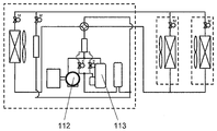
가스 히트 펌프는, 부분 부하시에는, 가스 엔진의 열효율이 저하하고, 공기 조화기로서의 운전 효율이 저하한다. 이것을 회피하기 위해, 가스 엔진에 의해 구동되는 엔진 구동 압축기보다 배제 용적이 작은 전원 구동 압축기를 병설하고, 부분 부하시는 전원 구동 압축기를 주체로 운전하고, 고부하시에는 가스 엔진을 주체로 운전하는, 이른바, 전원 구동 압축기와 엔진 구동 압축기의 하이브리드 실외 유닛이 제안되어 있다(예를 들면, 특허 문헌 1 참조, 도 5).When the gas heat pump is partially loaded, the thermal efficiency of the gas engine is lowered and the operation efficiency of the air conditioner is lowered. In order to avoid this, a power-driven compressor having a smaller displacement than an engine-driven compressor driven by a gas engine is installed in parallel, a power-driven compressor is mainly used for a partial load, and a gas engine is used as a main body , A power-driven compressor and a hybrid outdoor unit of an engine-driven compressor have been proposed (see, for example,
특허 문헌 1에 의하면, 공조 부하에 따라, 엔진 구동 압축기(112)만을 운전시킬지, 전원 구동 압축기(113)만을 운전시킬지, 혹은 엔진 구동 압축기(112)와 전원 구동 압축기(113)의 쌍방을 운전시킬지를 선택한다. 이로 인해, 구해지는 공조 부하에 따라, 가장 효율이 좋은 운전을 행할 수 있는 압축기를 선택하게 되고, 공조 부하의 크기에 관계없이 높은 효율을 얻을 수 있다고 하고 있다.According to the
그러나, 특허 문헌 1에 기재된 구성에 있어서, 배제 용적, 즉, 정격 능력이 다른 압축기를 동시에 구동하여 운전한 경우, 배제 용적이 작고 정격 능력이 낮은 압축기의 운전 신뢰성이 악화된다는 과제가 있다.However, in the structure described in
일반적으로, 정격 능력이 높은 압축기를 단독으로 운전한 경우, 정격 능력이 낮은 압축기를 단독으로 운전하는 경우에 비해, 고압(토출 압력)은 보다 높고, 저압(흡입 압력)은 보다 낮아지고, 고저 압력차가 커지는 경향이 있다. 냉방 운전시에서는, 실내기에 있어서의 냉매의 증발 온도로 거의 정해지는 흡입 압력에 대해서는, 압축기의 정격 능력의 차이에 의한 차는 작지만, 토출 압력에 대해서는 이 차가 커진다.In general, when a compressor having a high rated capacity is operated alone, a high pressure (discharge pressure) is higher, a low pressure (suction pressure) is lower, and a low pressure The car tends to get bigger. At the time of cooling operation, the suction pressure substantially determined by the evaporation temperature of the refrigerant in the indoor unit is small with respect to the difference in the rated capacity of the compressor, but this difference becomes large with respect to the discharge pressure.
예를 들면, 정격 능력 20HP의 엔진 구동 압축기와, 정격 능력 10HP의 전원 구동 압축기를 탑재한 하이브리드 실외 유닛에 있어서, 정격 능력 20HP의 엔진 구동 압축기를 단독으로 냉방 운전한 경우의 토출 압력은, 정격 능력 10HP의 전원 구동 압축기를 단독으로 냉방 운전한 경우보다 높아지는 경향이 있다. 그리고, 이 토출 압력의 차는, 단독으로 운전하는 엔진 구동 압축기의 운전 주파수와 전원 구동 압축기의 운전 주파수의 차, 즉, 엔진 구동 압축기가 토출하는 냉매 유량과 전원 구동 압축기가 토출하는 냉매 유량의 차가 클수록 현저해진다. For example, in a hybrid outdoor unit equipped with an engine-driven compressor having a rated capacity of 20HP and a power-driven compressor having a rated capacity of 10HP, the discharge pressure when the engine-driven compressor having a rated capacity of 20HP is solely operated for cooling, It tends to be higher than when the power-driven compressor of 10 HP is solely operated in the cooling mode. The difference between the discharge pressures becomes larger as the difference between the operating frequency of the engine-driven compressor operating alone and the operating frequency of the power-driven compressor becomes larger, that is, the difference between the refrigerant flow rate discharged by the engine drive compressor and the refrigerant flow rate discharged by the power- It becomes remarkable.
따라서, 상기 하이브리드 실외 유닛에 있어서, 양쪽의 압축기를 동시에 구동하고, 전원 구동 압축기의 운전 주파수를 줄이면, 전원 구동 압축기의 토출 압력은, 엔진 구동 압축기의 토출 압력에 끌려 현저하게 상승해 버리고, 전원 구동 압축기는 단독 운전하는 경우보다 큰 고저 압력차하에서 구동해야한다.Therefore, in the hybrid outdoor unit, when both the compressors are driven simultaneously and the operating frequency of the power-driven compressor is reduced, the discharge pressure of the power-driven compressor is significantly increased by the discharge pressure of the engine-driven compressor, The compressor must be driven at a higher and lower pressure differential than when operated alone.
압축기의 운전 주파수가 낮은 경우, 압축기 내에 있어서의 각 슬라이딩부에의 윤활유 공급이 막히고, 베어링에 있어서의 유막 형성이 곤란해진다. 따라서, 이와 같이 고저 압력차가 큰 상태에서의 구동은, 압축기 각 슬라이딩부에 있어서의 윤활이 곤란한 상태에서, 과대한 부하를 걸게 되고, 전원 구동 압축기의 운전 신뢰성을 저하시켜 버린다.When the operating frequency of the compressor is low, the supply of lubricating oil to each sliding portion in the compressor is blocked, and it becomes difficult to form an oil film in the bearing. Therefore, driving in a state in which the high and low pressure differences are large causes an excessive load in a state in which lubrication in each sliding portion of the compressor is difficult, and the reliability of operation of the power source driving compressor is lowered.
본 개시는, 상기 과제를 해결하는 것이며, 제1 압축기와, 제1 압축기보다 용량이 작은 제2 압축기를 병설한 공기 조화기의 실외 유닛에 있어서, 제2 압축기의 토출 압력이 제1 압축기의 토출 압력까지 끌어 올려지는 것을 막고, 제2 압축기의 운전 신뢰성을 향상시킨, 공기 조화기의 실외 유닛 및 제어 방법을 제공하는 것을 목적으로 한다.The present invention solves the problems described above and provides an outdoor unit of an air conditioner having a first compressor and a second compressor having a capacity smaller than that of the first compressor, And an object of the present invention is to provide an outdoor unit of an air conditioner and a control method thereof that prevent the compressor from being pulled up to a pressure and improve the operation reliability of the second compressor.
상기 과제를 해결하기 위해서, 본 개시의 공기 조화기의 실외 유닛에서는,In order to solve the above problem, in the outdoor unit of the air conditioner of the present disclosure,
제1 압축기와,A first compressor,
상기 제1 압축기보다 용량이 작은 제2 압축기와,A second compressor having a smaller capacity than the first compressor,
상기 제1 압축기로부터 토출된 냉매의 유통 방향을 전환하는 제1 전환부와,A first switch for switching the flow direction of the refrigerant discharged from the first compressor,
상기 제2 압축기로부터 토출된 냉매의 유통 방향을 전환하는 제2 전환부와,A second switching unit for switching the flow direction of the refrigerant discharged from the second compressor,
제1 실외 열교환기와,A first outdoor heat exchanger,
제2 실외 열교환기와,A second outdoor heat exchanger,
가스관 접속구와,A gas pipe connection port,
액관 접속구와,Liquid-
제어부를 구비하고,And a control unit,
상기 제어부는, 냉방 운전시에,Wherein the control unit, during a cooling operation,
상기 가스관 접속구를, 상기 제1 압축기의 흡입관과 상기 제2 압축기의 흡입관에 접속하고, 또한, The gas pipe connection port is connected to the suction pipe of the first compressor and the suction pipe of the second compressor,
상기 액관 접속구를, 상기 제1 실외 열교환기와 제1 전환부를 개재하여 상기 제1 압축기의 토출관에 접속하고, 또한, 상기 제2 실외 열교환기와 제2 전환부를 개재하여 상기 제2 압축기의 토출관에 접속하도록, 상기 제1 전환부 및 상기 제2 전환부를 전환한다. And the liquid pipe connection port is connected to the discharge pipe of the first compressor through the first outdoor heat exchanger and the first switching unit and is connected to the discharge pipe of the second compressor through the second outdoor heat exchanger and the second switching unit The first switching unit and the second switching unit are switched.
또, 제1 전환부와 제1 실외 열교환기 사이의 배관과, 제2 전환부와 제2 실외 열교환기 사이의 배관을 연결하는 바이패스 회로와, 바이패스 회로의 연통을 제어하는 개폐 밸브를 더 구비하다.A bypass circuit for connecting a pipe between the first switching unit and the first outdoor heat exchanger, a pipe between the second switching unit and the second outdoor heat exchanger, and an open / close valve for controlling the communication of the bypass circuit Be equipped.
이로 인해, 제1 압축기와, 제1 압축기보다 용량이 작은 제2 압축기가 동시에 구동하는 냉방 운전시에 있어서, 제2 압축기가 토출하는 냉매 유량이, 제1 압축기가 토출하는 냉매 유량보다 극단적으로 적은 경우라도, 제1 팽창 밸브의 개구도를 조정함으로써, 제2 압축기의 토출 압력을 제1 압축기의 토출 압력보다 낮은 상태로 유지한다. 따라서, 용량이 작은 제2 압축기의 토출 압력이, 제1 압축기의 토출 압력으로까지 끌어 올려지는 일은 없다.As a result, in the cooling operation in which the first compressor and the second compressor having a capacity smaller than that of the first compressor are simultaneously driven, the flow rate of the refrigerant discharged from the second compressor is extremely smaller than the flow rate of refrigerant discharged from the first compressor The discharge pressure of the second compressor is maintained lower than the discharge pressure of the first compressor by adjusting the opening degree of the first expansion valve. Therefore, the discharge pressure of the second compressor having a small capacity is not lifted up to the discharge pressure of the first compressor.
또, 공기 조화기의 실외 유닛이, 상부에 송풍 팬, 측면에 제1 실외 열교환기와 제2 실외 열교환기가 일체로 성형된 상취 유닛에서, 또한 제1 실외 열교환기를 제2 실외 열교환기 위에 배치하는 구성일 때, 제1 압축기와, 제2 압축기가 토출하는 각각의 냉매 유량이 최소이고, 또한, 제1 압축기의 토출 압력과 제2 압축기의 토출 압력이 거의 같은 냉방 운전시에 있어서, 개폐 밸브를 개방, 제2 팽창 밸브를 폐쇄로 함으로써, 제1 압축기의 토출 냉매와 제2 압축기의 토출 냉매를, 모두 공기 유속이 빠르고 열교환 효율이 높은 제1 실외 열교환기에서 공기와 열교환시킨다.The outdoor unit of the air conditioner includes a blowing fan at an upper portion thereof, an outlet unit in which a first outdoor heat exchanger and a second outdoor heat exchanger are integrally formed on a side surface thereof, and a first outdoor heat exchanger disposed on the second outdoor heat exchanger In the cooling operation in which the flow rates of the respective refrigerants discharged from the first compressor and the second compressor are minimum and the discharge pressure of the first compressor and the discharge pressure of the second compressor are substantially equal to each other, And the second expansion valve is closed so that the discharge refrigerant of the first compressor and the discharge refrigerant of the second compressor exchange heat with the air in the first outdoor heat exchanger having a high air flow rate and a high heat exchange efficiency.
또한, 제1 압축기만이 가동하는 경우, 개폐 밸브를 폐쇄로 함으로써, 제1 압축기의 토출 냉매를, 공기 유속이 빠르고 열교환 효율이 높은 제1 실외 열교환기로 공기와 열교환시킨다. 또, 제2 압축기만이 가동하는 경우라도, 개폐 밸브를 개방, 제2 팽창 밸브를 폐쇄로 함으로써, 제2 압축기의 토출 냉매를, 제1 실외 열교환기에서 공기와 열교환시킨다.Further, when only the first compressor is operated, the discharge refrigerant of the first compressor is heat-exchanged with the air by the first outdoor heat exchanger which has a high air flow rate and a high heat exchange efficiency by closing the open / close valve. Further, even when only the second compressor is operated, the discharge refrigerant of the second compressor is heat-exchanged with air in the first outdoor heat exchanger by opening the on-off valve and closing the second expansion valve.
또, 본 개시의 공기 조화기의 실외 유닛에서는, 제1 압축기와, 제1 압축기보다 용량이 작은 제2 압축기와, 제1 압축기의 토출 냉매의 유통 방향을 전환하는 제1 전환부와, 제2 압축기의 토출 냉매의 유통 방향을 전환하는 제2 전환부와, 제1 실외 열교환기와, 제2 실외 열교환기와, 엔진 배열과 냉매를 열교환시키는 제3 실외 열교환기와, 가스관 접속구와, 액관 접속구와, 제어부와, 제1 전환부와 제1 실외 열교환기 사이의 배관과, 제2 전환부와 제2 실외 열교환기 사이의 배관을 연결하는 바이패스 회로와, 바이패스 회로의 연통을 제어하는 개폐 밸브를 구비하고, 상기 제1 전환부와 상기 제1 실외 열교환기의 사이에 설치한, 상기 제1 실외 열교환기의 방향으로만 유통시키고, 역방향으로는 유통시키지 않는 제1 역지 밸브와, 상기 제1 전환부와 상기 가스관 접속구의 사이에 설치한, 상기 가스관 접속구의 방향으로만 유통시키고, 역방향으로는 유통시키지 않는 제2 역지 밸브와, 상기 제2 전환부와 상기 제2 실외 열교환기의 사이에 설치한, 상기 제2 실외 열교환기의 방향으로만 유통시키고, 역방향으로는 유통시키지 않는 제3 역지 밸브와, 상기 제2 전환부와 상기 가스관 접속구의 사이에 설치한, 상기 가스관 접속구의 방향으로만 유통시키고, 역방향으로는 유통시키지 않는 제4 역지 밸브를 구비하고, 제어부는, 제상(除霜) 운전시에, 가스관 접속구를, 제2 압축기의 토출관에 접속하고, 액관 접속구를, 제3 실외 열교환기를 개재하여 제1 압축기 및 제2 압축기의 흡입관에 접속하고, 또한, 액관 접속구를 제2 실외 열교환기와 제1 전환부를 개재하여, 또는, 제1 실외 열교환기와 제1 전환부를 개재하여, 제1 압축기의 토출관에 선택적으로 접속하도록, 제1 전환부 및 제2 전환부를 전환하고, 개폐 밸브를 개폐한다.In the outdoor unit of the present air conditioner, the first compressor, the second compressor having a capacity smaller than that of the first compressor, the first switching portion switching the flow direction of the discharge refrigerant of the first compressor, A first outdoor heat exchanger, a second outdoor heat exchanger, a third outdoor heat exchanger for exchanging heat between the engine arrangement and the refrigerant, a gas pipe connection port, a liquid pipe connection port, A bypass circuit for connecting the piping between the first switching unit and the first outdoor heat exchanger, the piping between the second switching unit and the second outdoor heat exchanger, and an opening / closing valve for controlling the communication of the bypass circuit A first check valve which is provided between the first switching unit and the first outdoor heat exchanger and flows only in the direction of the first outdoor heat exchanger and does not flow in the reverse direction; And the gas- A second check valve provided between the second switching unit and the second outdoor heat exchanger, the second check valve being provided between the second switching unit and the second outdoor heat exchanger, the second check valve being provided between the second switching unit and the second outdoor heat exchanger, A third check valve which circulates only in the direction of the heat exchanger and does not circulate in the reverse direction and a second check valve which is provided between the second switching portion and the gas pipe connection port only in the direction of the gas pipe connection port, Wherein the control unit is configured to connect the gas pipe connection port to the discharge pipe of the second compressor and to connect the liquid pipe connection port to the first compressor through the third outdoor heat exchanger when the defrosting operation is performed, And the liquid pipe connection port is connected to the suction pipe of the second compressor through the second outdoor heat exchanger and the first switching unit or via the first outdoor heat exchanger and the first switching unit, The first switching unit and the second switching unit are switched to selectively connect to the discharge pipe, and the opening / closing valve is opened / closed.
이로 인해, 난방 운전을 계속하면서, 제상 운전을 행할 수 있다.As a result, the defrosting operation can be performed while continuing the heating operation.
제1 압축기와 제1 압축기보다 용량이 작은 제2 압축기를 동시에 구동하는 냉방 운전시에 있어서, 제2 압축기가 토출하는 냉매 유량이 제2 압축기보다 극단적으로 적은 경우라도, 제2 압축기의 토출 압력의 과승(過昇)을 방지하고, 제2 압축기의 운전 신뢰성을 향상시킬 수 있다.Even when the refrigerant flow rate discharged by the second compressor is extremely smaller than that of the second compressor during the cooling operation for simultaneously driving the first compressor and the second compressor having a capacity smaller than that of the first compressor, It is possible to prevent excessive increase and improve the operation reliability of the second compressor.
또, 제1 압축기와 제2 압축기를 동시에 구동하는 냉방 운전시에 있어서, 제2 압축기가 토출하는 냉매 유량에 관계없이, 제2 압축기의 토출 압력이 제1 압축기의 토출 압력까지 끌어 올려지는 일은 없기 때문에, 제2 압축기의 운전 효율 저하를 방지할 수 있다.In the cooling operation for simultaneously driving the first compressor and the second compressor, the discharge pressure of the second compressor does not rise up to the discharge pressure of the first compressor regardless of the flow rate of the refrigerant discharged from the second compressor Therefore, the operating efficiency of the second compressor can be prevented from lowering.
또, 공기 조화기의 실외 유닛이 상취 유닛에서, 제1 압축기와 제2 압축기가 모두 최저 주파수로 구동하는 냉방 운전시에 있어서, 제1 압축기와 제2 압축기의 토출 압력을 모두 저하시키고, 압축기 각 슬라이딩부에 있어서의 윤활이 곤란한 운전 상태라도, 제1 압축기 및 제2 압축기의 운전 신뢰성을 향상시킬 수 있다.In the cooling operation in which the outdoor unit of the air conditioner is driven by the first compressor and the second compressor both at the lowest frequency in the compressor unit, both the discharge pressures of the first compressor and the second compressor are lowered, The operation reliability of the first compressor and the second compressor can be improved even in an operating state in which lubrication in the sliding portion is difficult.
또한, 제1 압축기, 혹은, 제2 압축기가 단독으로 가동하는 경우라도, 제1 실외 열교환기와 제2 실외 열교환기 중, 열교환 효율이 높은 열교환기에서 외기와 열교환시키므로, 공기 조화기의 운전 효율을 향상시킬 수 있다.Further, even when the first compressor or the second compressor alone operates, heat exchange is performed between the first outdoor heat exchanger and the second outdoor heat exchanger in the heat exchanger having a high heat exchange efficiency, so that the operation efficiency of the air conditioner is improved Can be improved.
도 1은, 본 개시의 실시의 형태 1에 있어서의 공기 조화기의 냉동 사이클도
도 2는, 본 개시의 실시의 형태 2에 있어서의 공기 조화기의 냉동 사이클도
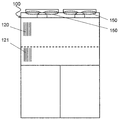
도 3은, 실외 유닛의 외관도
도 4는, 본 개시의 실시의 형태 3에 있어서의 공기 조화기의 냉동 사이클도
도 5는, 종래 기술에 있어서의 공기 조화기의 냉동 사이클도1 is a diagram showing a refrigeration cycle diagram of an air conditioner according to a first embodiment of the present disclosure
Fig. 2 is a diagram showing the refrigeration cycle of the air conditioner according to the second embodiment of the present disclosure
Fig. 3 is a view showing the appearance of the outdoor unit
4 is a diagram showing the refrigeration cycle of the air conditioner according to the third embodiment of the present disclosure
Fig. 5 is a view showing the refrigeration cycle of the air conditioner in the prior art
제1 개시는,In the first disclosure,
제1 압축기와, A first compressor,
상기 제1 압축기보다 용량이 작은 제2 압축기와,A second compressor having a smaller capacity than the first compressor,
상기 제1 압축기로부터 토출된 냉매의 유통 방향을 전환하는 제1 전환부와,A first switch for switching the flow direction of the refrigerant discharged from the first compressor,
상기 제2 압축기로부터 토출된 냉매의 유통 방향을 전환하는 제2 전환부와,A second switching unit for switching the flow direction of the refrigerant discharged from the second compressor,
제1 실외 열교환기와,A first outdoor heat exchanger,
제2 실외 열교환기와,A second outdoor heat exchanger,
가스관 접속구와,A gas pipe connection port,
액관 접속구와,Liquid-
제어부를 구비하고,And a control unit,
상기 제어부는, 냉방 운전시에,Wherein the control unit, during a cooling operation,
상기 가스관 접속구를, 상기 제1 압축기의 흡입관과 상기 제2 압축기의 흡입관에 접속하고, 또한, The gas pipe connection port is connected to the suction pipe of the first compressor and the suction pipe of the second compressor,
상기 액관 접속구를, 상기 제1 실외 열교환기와 제1 전환부를 개재하여 상기 제1 압축기의 토출관에 접속하고, 또한, 상기 제2 실외 열교환기와 제2 전환부를 개재하여 상기 제2 압축기의 토출관에 접속하도록, 상기 제1 전환부 및 상기 제2 전환부를 전환하는, 공기 조화기의 실외 유닛이다.And the liquid pipe connection port is connected to the discharge pipe of the first compressor through the first outdoor heat exchanger and the first switching unit and is connected to the discharge pipe of the second compressor through the second outdoor heat exchanger and the second switching unit And switches between the first switching portion and the second switching portion so as to be connected to the outdoor unit.
제1 개시에 기재된 공기 조화기의 실외 유닛은, 상기 제1 실외 열교환기를 흐르는 냉매의 유량을 조정하는 제1 팽창 밸브를 더 구비하고 있어도 된다. 또, 상기 제어부는, 상기 냉방 운전시에, 상기 액관 접속구를, 상기 제1 팽창 밸브, 상기 제1 실외 열교환기, 및 제1 전환부를 개재하여 상기 제1 압축기의 토출관에 접속하고, 또한, 상기 제2 실외 열교환기와 제2 전환부를 개재하여 상기 제2 압축기의 토출관에 접속하도록, 상기 제1 전환부 및 상기 제2 전환부를 전환해도 된다. The outdoor unit of the air conditioner according to the first aspect may further include a first expansion valve for adjusting the flow rate of the refrigerant flowing through the first outdoor heat exchanger. The control unit may connect the liquid pipe connection port to the discharge pipe of the first compressor through the first expansion valve, the first outdoor heat exchanger, and the first switching unit at the time of the cooling operation, The first switching unit and the second switching unit may be switched so as to be connected to the discharge pipe of the second compressor through the second outdoor heat exchanger and the second switching unit.
이로 인해, 냉방 운전시에 있어서, 제1 압축기와, 제1 압축기보다 용량이 작은 제2 압축기가 동시에 구동하고, 제2 압축기가 토출하는 냉매 유량이, 제1 압축기가 토출하는 냉매 유량보다 극단적으로 적은 경우라도, 제1 팽창 밸브(제1 실외 유닛 감압 밸브(130))의 개구도를 조정함으로써, 제2 압축기의 토출 압력을 제1 압축기의 토출 압력보다 낮은 상태로 유지한다. 따라서, 용량이 작은 제2 압축기의 토출 압력이, 제1 압축기의 토출 압력으로까지 끌어 올려지는 일은 없다.As a result, during the cooling operation, the first compressor and the second compressor having a capacity smaller than that of the first compressor are driven at the same time, and the refrigerant flow rate discharged from the second compressor is extremely lower than the refrigerant flow rate discharged from the first compressor The discharge pressure of the second compressor is kept lower than the discharge pressure of the first compressor by adjusting the opening degree of the first expansion valve (first outdoor unit pressure reducing valve 130). Therefore, the discharge pressure of the second compressor having a small capacity is not lifted up to the discharge pressure of the first compressor.
따라서, 본 개시에서는, 냉방 운전시에 있어서, 제1 압축기보다 용량이 작은 제2 압축기의 토출 압력의 과승을 방지하고, 제2 압축기의 운전 신뢰성을 향상시킬 수 있다.Therefore, in the present disclosure, it is possible to prevent over-discharge of the discharge pressure of the second compressor having a capacity smaller than that of the first compressor during the cooling operation and improve the operation reliability of the second compressor.
제2 개시는, 제1 개시에 있어서, 제1 전환 밸브와 제1 실외 열교환기 사이의 배관과, 제2 전환 밸브와 제2 실외 열교환기 사이의 배관을 연결하는 바이패스 회로와, 바이패스 회로의 연통을 제어하는 개폐 밸브를 구비하는 공기 조화기의 실외 유닛이다.The second invention is characterized in that, in the first disclosure, a bypass circuit for connecting a pipe between the first switching valve and the first outdoor heat exchanger, a pipe between the second switching valve and the second outdoor heat exchanger, And an opening / closing valve for controlling communication of the outdoor unit.
이로 인해, 예를 들면 공기 조화기의 실외 유닛이 상취 유닛이고, 제1 압축기와, 제1 압축기보다 용량이 작은 제2 압축기가 토출하는 각각의 냉매 유량이 최소이고(제1 압축기와 제2 압축기가 모두 최저 운전 주파수로 구동), 또한, 제1 압축기의 토출 압력과 제2 압축기의 토출 압력이 거의 같은 냉방 운전시에 있어서, 개폐 밸브를 개방, 제2 팽창 밸브를 폐쇄로 함으로써, 제1 압축기의 토출 냉매와 제2 압축기의 토출 냉매를, 모두 공기 유속이 빠르고 열교환 능력이 높은 제1 실외 열교환기에서 공기와 열교환시킨다.Therefore, for example, when the outdoor unit of the air conditioner is the rechargeable unit and the flow rate of each refrigerant discharged from the first compressor and the second compressor having a capacity smaller than that of the first compressor is minimum (the first compressor and the second compressor Closing valve is opened and the second expansion valve is closed at the time of cooling operation in which the discharge pressure of the first compressor and the discharge pressure of the second compressor are substantially equal to each other, And the discharge refrigerant of the second compressor exchange heat with air in the first outdoor heat exchanger which has a high air flow rate and a high heat exchange capacity.
이러한 운전 조건하에서 제1 실외 열교환기만을 이용한 경우, 제1 실외 열교환기와 제2 실외 열교환기를 이용한 경우에 비해, 전열면적 저감의 영향보다, 제1 실외 열교환기 내부에 있어서의 냉매 유속 상승에 의한 열전달율 향상 효과가 크고, 냉매로부터 공기에의 방열량은 증대하고, 제1 압축기 및 제2 압축기의 토출 압력은 저하한다.In the case where only the first outdoor heat exchanger is used under these operating conditions, the heat transfer rate due to the rise of the refrigerant flow rate in the first outdoor heat exchanger is smaller than the influence of the reduction of the heat transfer area, as compared with the case of using the first outdoor heat exchanger and the second outdoor heat exchanger. The improvement effect is large, the amount of heat released from the refrigerant to the air increases, and the discharge pressure of the first compressor and the second compressor decreases.
따라서, 본 개시에서는, 제1 압축기와 제2 압축기가 모두 최저 주파수로 구동하는 냉방 운전시에 있어서, 제1 압축기와 제2 압축기의 토출 압력을 모두 저하시키고, 압축기 각 슬라이딩부에 있어서의 윤활이 곤란한 운전 상태라도, 제1 압축기 및 제2 압축기의 운전 신뢰성을 향상시킬 수 있다.Therefore, in the present disclosure, in the cooling operation in which both of the first compressor and the second compressor are driven at the lowest frequency, the discharge pressures of both the first compressor and the second compressor are lowered, The operational reliability of the first compressor and the second compressor can be improved even in a difficult operating condition.
또, 제1 압축기만이 가동하는 경우, 개폐 밸브를 폐쇄로 함으로써, 제1 압축기의 토출 냉매를, 공기 유속이 빠르고 열교환 효율이 높은 제1 실외 열교환기에서 공기와 열교환시키고, 제2 압축기만이 가동하는 경우라도, 개폐 밸브를 개방, 제2 팽창 밸브를 폐쇄로 함으로써, 제2 압축기의 토출 냉매를, 제1 실외 열교환기에서 공기와 열교환시킨다.In the case where only the first compressor is operated, the discharge refrigerant of the first compressor is heat-exchanged with air in the first outdoor heat exchanger having a high air flow rate and high heat exchange efficiency by closing the open / close valve, The first outdoor heat exchanger exchanges heat with the refrigerant discharged from the second compressor by opening the on-off valve and closing the second expansion valve.
따라서, 본 개시에서는, 제1 압축기, 혹은, 제2 압축기가 단독으로 가동하는 경우라도, 제1 실외 열교환기와 제2 실외 열교환기 중, 열교환 능력이 높은 열교환기에서 외기와 열교환시키므로, 공기 조화기의 운전 효율을 향상시킬 수 있다.Therefore, in the present disclosure, even when the first compressor or the second compressor alone operates, the heat exchanger exchanges heat with the outside air in the heat exchanger having a high heat exchange capacity, among the first outdoor heat exchanger and the second outdoor heat exchanger, Can be improved.
제3 개시는, 제2 개시에 있어서, 제1 실외 열교환기의 단위면적당 열교환 능력을 제2 실외 열교환기보다 높게 설정하고, 냉방 운전의 제어부는, 제1 압축기와 제2 압축기의 양쪽을 저운전 주파수로 냉방 운전하는 경우에, 개폐 밸브를 개방으로 하고, 제2 실외 열교환기의 출구의 제2 팽창 밸브(제2 실외 유닛 감압 밸브(131))를 폐쇄로 함으로써, 제1 압축기와 제2 압축기의 양쪽의 토출 냉매를, 제1 실외 열교환기로 열교환시키는 공기 조화기의 실외 유닛이다.In the third disclosure, in the second disclosure, the heat exchange capacity per unit area of the first outdoor heat exchanger is set to be higher than that of the second outdoor heat exchanger, and the control section of the cooling operation places both the first compressor and the second compressor in a low- And the second expansion valve (the second outdoor unit pressure reducing valve 131) at the outlet of the second outdoor heat exchanger is closed, the first compressor and the second compressor Out refrigerant from the first outdoor heat exchanger to the first outdoor heat exchanger.
이로 인해, 제1 압축기와 제2 압축기가 모두 저주파수로 구동하는 냉방 운전시에 있어서, 제1 압축기와 제2 압축기의 토출 압력을 모두 저하시키고, 압축기 각 슬라이딩부에 있어서의 윤활이 곤란한 운전 상태라도, 제1 압축기 및 제2 압축기의 운전 신뢰성을 향상시킬 수 있다.As a result, even in a driving state in which both the first compressor and the second compressor are driven at a low frequency and the discharge pressures of the first compressor and the second compressor are both lowered and lubrication in each sliding portion of the compressor is difficult , The operation reliability of the first compressor and the second compressor can be improved.
제4 개시는, 제2 개시 또는 제3 개시에 있어서, 냉방 운전의 제어부는, 제1 압축기가 단독으로 가동할 때, 개폐 밸브를 폐쇄로 함으로써, 제1 압축기의 토출 냉매를, 제1 실외 열교환기로 열교환시키는 공기 조화기의 실외 유닛이다.The fourth aspect of the present invention is the refrigerating operation control device according to the second or third aspect, wherein when the first compressor is operated alone, the open / close valve is closed so that the discharged refrigerant of the first compressor is discharged to the first outdoor heat exchange The outdoor unit of the air conditioner exchanges heat with the air.
이로 인해, 제1 압축기를 단독으로 구동하는 냉방 운전시에 있어서, 열교환 능력이 높은 제1 열교환기에서 외기와 열교환시키므로, 공기 조화기의 운전 효율을 향상시킬 수 있다.As a result, in the cooling operation for independently driving the first compressor, the first heat exchanger having high heat exchange ability performs heat exchange with the outside air, so that the operation efficiency of the air conditioner can be improved.
제5 개시는, 제2 개시 또는 제3 개시에 있어서, 냉방 운전의 제어부는, 제2 압축기가 단독으로 가동할 때, 개폐 밸브를 개방으로 하고, 제2 실외 열교환기의 출구의 제2 팽창 밸브를 폐쇄로 함으로써, 제2 압축기의 토출 냉매를, 제1 실외 열교환기에서 열교환시키는 공기 조화기의 실외 유닛이다.The fifth aspect of the present invention is the refrigerator according to the second or third aspect, wherein the control unit of the cooling operation is such that when the second compressor is operated alone, the opening / closing valve is opened and the second expansion valve Is an outdoor unit of the air conditioner that exchanges heat with refrigerant discharged from the second compressor in the first outdoor heat exchanger.
이로 인해, 제2 압축기를 단독으로 구동하는 냉방 운전시에 있어서, 열교환 능력이 높은 제1 열교환기에서 외기와 열교환시키므로, 공기 조화기의 운전 효율을 향상시킬 수 있다.As a result, in the cooling operation for independently driving the second compressor, the first heat exchanger having a high heat exchange ability performs heat exchange with the outside air, thereby improving the operation efficiency of the air conditioner.
제6 개시는, 제1 개시에 있어서, 또한, 엔진 배열과 냉매를 열교환시키는 제3 실외 열교환기와, 상기 제1 전환부와 상기 제1 실외 열교환기 사이의 배관과, 상기 제2 전환부와 상기 제2 실외 열교환기 사이의 배관을 연결하는 바이패스 회로와, 상기 바이패스 회로의 연통을 제어하는 개폐 밸브와, 상기 제1 전환부와 상기 제1 실외 열교환기의 사이에 설치한, 상기 제1 실외 열교환기의 방향으로만 유통시키고, 역방향으로는 유통시키지 않는 제1 역지 밸브와, 상기 제1 전환부와 상기 가스관 접속구의 사이에 설치한, 상기 가스관 접속구의 방향으로만 유통시키고, 역방향으로는 유통시키지 않는 제2 역지 밸브와, 상기 제2 전환부와 상기 제2 실외 열교환기의 사이에 설치한, 상기 제2 실외 열교환기의 방향으로만 유통시키고, 역방향으로는 유통시키지 않는 제3 역지 밸브와, 상기 제2 전환부와 상기 가스관 접속구의 사이에 설치한, 상기 가스관 접속구의 방향으로만 유통시키고, 역방향으로는 유통시키지 않는 제4 역지 밸브를 구비하고, 상기 제어부는, 제상 운전시에, 상기 가스관 접속구를, 상기 제2 압축기의 토출관에 접속하고, 상기 액관 접속구를, 상기 제3 실외 열교환기를 개재하여 상기 제1 압축기 및 상기 제2 압축기의 흡입관에 접속하고, 또한, 상기 액관 접속구를, 상기 제2 실외 열교환기와 제1 전환부를 개재하여, 또는, 상기 제1 실외 열교환기와 제1 전환부를 개재하여, 상기 제1 압축기의 토출관에 선택적으로 접속하도록, 상기 제1 전환부 및 상기 제2 전환부를 전환하고, 상기 개폐 밸브를 개폐하는 공기 조화기의 실외 유닛이다.A sixth aspect of the present invention is the refrigerating machine according to the first aspect, further comprising: a third outdoor heat exchanger for exchanging heat between the engine arrangement and the refrigerant; a pipe between the first switching unit and the first outdoor heat exchanger; A bypass circuit for connecting the piping between the first outdoor heat exchanger and the second outdoor heat exchanger, an opening / closing valve for controlling the communication of the bypass circuit, and a second switching valve provided between the first switching unit and the first outdoor heat exchanger, A first check valve which communicates only in the direction of the outdoor heat exchanger and does not flow in the reverse direction and a second check valve which communicates only in the direction of the gas pipe connection port provided between the first switching portion and the gas pipe connection port, A second check valve which does not circulate in the direction of the first outdoor heat exchanger and a second check valve which does not circulate in the direction of the second outdoor heat exchanger provided between the second switching unit and the second outdoor heat exchanger, And a fourth check valve which is provided between the second switching portion and the gas pipe connection port and flows only in the direction of the gas pipe connection port and does not flow in the reverse direction, , The gas pipe connection port is connected to the discharge pipe of the second compressor and the liquid pipe connection port is connected to the suction pipe of the first compressor and the second compressor through the third outdoor heat exchanger, The liquid pipe connection port is selectively connected to the discharge pipe of the first compressor through the second outdoor heat exchanger and the first switching unit or via the first outdoor heat exchanger and the first switching unit, And an outdoor unit of the air conditioner which switches the second switching portion and opens and closes the opening / closing valve.
이로 인해, 난방 운전을 계속하면서, 제상 운전을 행할 수 있다.As a result, the defrosting operation can be performed while continuing the heating operation.
제7 개시는, 제1 압축기와, 제1 압축기보다 용량이 작은 제2 압축기와, 제1 압축기의 토출 냉매의 유통 방향을 전환하는 제1 전환부와, 제2 압축기의 토출 냉매의 유통 방향을 전환하는 제2 전환부와, 제1 실외 열교환기와, 제2 실외 열교환기와, 가스관 접속구와, 액관 접속구를 구비하고, 냉방 운전시에, 가스관 접속구를, 제1 압축기의 흡입관과 제2 압축기의 흡입관에 접속하고, 액관 접속구를, 제1 실외 열교환기와 제1 전환부를 개재하여 제1 압축기의 토출관에 접속하고, 또한, 제2 실외 열교환기와 제2 전환부를 개재하여 제2 압축기의 토출관에 접속하도록, 제1 전환부 및 상기 제2 전환부를 전환하는 공기 조화기의 제어 방법이다.A seventh aspect of the present invention is a refrigerant compressor comprising a first compressor, a second compressor having a capacity smaller than that of the first compressor, a first switching portion for switching the flow direction of the refrigerant discharged from the first compressor, A second outdoor heat exchanger, a gas pipe connection port, and a liquid pipe connection port, wherein the gas pipe connection port is connected to the suction pipe of the first compressor and the suction pipe of the second compressor, And the liquid pipe connection port is connected to the discharge pipe of the first compressor through the first outdoor heat exchanger and the first switching section and connected to the discharge pipe of the second compressor through the second outdoor heat exchanger and the second switching section , The first switching unit and the second switching unit are switched.
이로 인해, 냉방 운전시에 있어서, 제1 압축기와, 제1 압축기보다 용량이 작은 제2 압축기가 동시에 구동하고, 제2 압축기가 토출하는 냉매 유량이, 제1 압축기가 토출하는 냉매 유량보다 극단적으로 적은 경우라도, 제1 팽창 밸브의 개구도를 조정함으로써, 제2 압축기의 토출 압력을 제1 압축기의 토출 압력보다 낮은 상태로 유지한다. 따라서, 용량이 작은 제2 압축기의 토출 압력이, 제1 압축기의 토출 압력으로까지 끌어 올려지는 일은 없다.As a result, during the cooling operation, the first compressor and the second compressor having a capacity smaller than that of the first compressor are driven at the same time, and the refrigerant flow rate discharged from the second compressor is extremely lower than the refrigerant flow rate discharged from the first compressor The discharge pressure of the second compressor is maintained lower than the discharge pressure of the first compressor by adjusting the degree of opening of the first expansion valve. Therefore, the discharge pressure of the second compressor having a small capacity is not lifted up to the discharge pressure of the first compressor.
따라서, 본 개시에서는, 냉방 운전시에 있어서, 제1 압축기보다 용량이 작은 제2 압축기의 토출 압력의 과승을 방지하고, 제2 압축기의 운전 신뢰성을 향상시킬 수 있다.Therefore, in the present disclosure, it is possible to prevent over-discharge of the discharge pressure of the second compressor having a capacity smaller than that of the first compressor during the cooling operation and improve the operation reliability of the second compressor.
이하, 본 개시의 실시의 형태에 대해서, 도면을 참조하면서 설명한다. 또한, 이 실시 형태에 의해, 본 개시가 한정되는 것은 아니다.Hereinafter, embodiments of the present disclosure will be described with reference to the drawings. In addition, the present disclosure is not limited by this embodiment.
(실시의 형태 1)(Embodiment Mode 1)
본 실시의 형태의 공기 조화기의 냉동 사이클 구성을 도 1에 나타낸다. 도 1의 공기 조화기는, 실외 유닛 1대에 대해서, 실내기가 2대 접속한, 이른바 트윈 구성으로 되어 있다. 또한, 냉동 사이클 구성에 관해서는, 도 1에 나타낸 것으로 한정되지 않는다. 예를 들면, 실외 유닛은 2대 이상, 실내기도 3대 이상, 병렬로 접속 가능하다.Fig. 1 shows a refrigerating cycle configuration of the air conditioner of the present embodiment. The air conditioner of Fig. 1 has a so-called twin configuration in which two indoor units are connected to one outdoor unit. The configuration of the refrigeration cycle is not limited to that shown in Fig. For example, two or more out-room units and three or more indoor units can be connected in parallel.
100은 실외 유닛이며, 실외 유닛(100)과 실내기(200, 210)는, 냉매가 유통하는 배관으로 연결되어 있다. 300은 냉난방 운전의 제어부이다. 실외 유닛(100)에 있어서, 111은 예를 들면 가스를 구동원으로 하는 엔진, 112는 엔진(111)으로부터 구동력을 얻어 냉매를 압축하는 제1 압축기(엔진 구동 압축기), 113은 상용 전원 등 전력에 의해 구동하는 제2 압축기(전원 구동 압축기)이다. 제1 압축기(112)의 배제 용적은, 제2 압축기(113)의 배제 용적보다 크다. 또, 제1 압축기(112), 제2 압축기(113)의 윤활유는 같은 냉동기유로 한다.
114는 어큐뮬레이터이며, 제1 압축기(112)의 흡입 배관과 제2 압축기(113)의 흡입 배관의 합류점으로부터, 양 압축기와는 반대측의 냉매 배관에 접속되고, 양 압축기에 가스 냉매를 공급한다.
115는 제1 압축기용 유분리기이며, 제1 압축기(112)의 토출 배관에 설치되고, 제1 압축기(112)의 토출 가스에 포함되는 냉동기유를 분리한다. 제1 압축기용 유분리기(115)에서 분리된 냉동기유는, 제1 압축기(112)의 흡입 배관에 제1 압축기용 오일 템퍼링관(115a)에 의해 되돌려진다. 제1 압축기용 오일 템퍼링관(115a)의 연통은, 제1 압축기용 오일 템퍼링관 개폐 밸브(115b)의 개폐에 의해 제어된다.
116은 제2 압축기용 유분리기이며, 제2 압축기(113)의 토출 배관에 설치되고, 제2 압축기(113)의 토출 가스에 포함되는 냉동기유를 분리한다. 제2 압축기용 유분리기(116)에서 분리된 냉동기유는, 제2 압축기(113)의 흡입 배관에 제2 압축기용 오일 템퍼링관(116a)에 의해 되돌려진다. 제2 압축기용 오일 템퍼링관(116a)의 연통은, 제2 압축기용 오일 템퍼링관 개폐 밸브(116b)의 개폐에 의해 제어된다.
또한, 제1 압축기용 오일 템퍼링관(115a)과 제2 압축기용 오일 템퍼링관(116a)은 합류시키고, 제1 압축기용 유분리기(115)에서 분리된 냉동기유와 제2 압축기용 유분리기(116)에서 분리된 냉동기유를 정리하여, 제1 압축기(112)와 제2 압축기(113)로 되돌리는 구성으로 해도 된다. 이때, 냉동기유의 반환처는, 어큐뮬레이터(114)와, 제1 압축기(112)의 흡입 배관과 제2 압축기(113)의 흡입 배관의 합류점의 사이로 한다.Further, the
117은, 냉방 운전과 난방 운전에서, 제1 압축기(112)의 토출 냉매를 흘리는 경로를 전환하는 제1 사방 밸브이다. 또, 118은, 냉방 운전과 난방 운전에서, 제2 압축기(113)의 토출 냉매를 흘리는 경로를 전환하는 제2 사방 밸브이다. 도 1에 있어서, 실선에 냉매를 흘리는 경우는 냉방 운전, 점선에 냉매를 흘리는 경우는 난방 운전이 된다.
120은, 그 일단이 제1 사방 밸브와 접속하는 제1 실외 열교환기, 121은, 그 일단이 제2 사방 밸브와 접속하는 제2 실외 열교환기이다. 제1 실외 열교환기(120), 제2 실외 열교환기(121)에는, 핀 & 튜브 열교환기, 마이크로 튜브 열교환기 등이 이용된다. 실외 송풍 팬(150)에 의해 실외 유닛(100)의 주위의 공기가 공급되고, 제1 실외 열교환기(120) 및 제2 실외 열교환기(121)의 튜브 내부를 흐르는 냉매와 핀을 통과하는 공기가 열교환을 행한다.120 is a first outdoor heat exchanger whose one end is connected to the first four-way valve, and 121 is a second outdoor heat exchanger whose one end is connected to the second four-way valve. For the first
122는, 엔진(111)의 냉각에 이용한 고온의 냉각수와 냉매의 열교환을 행하는 엔진 배열 열교환기이며, 난방시에 이용한다. 엔진 배열 열교환기에는 플레이트식 열교환기가 이용된다.122 is an engine arrangement heat exchanger for performing heat exchange between high temperature cooling water used for cooling the
130은, 제1 실외 열교환기와 접속하고, 냉매를 감압, 팽창시키는 제1 실외 유닛 감압 밸브이다. 또, 131은, 제2 실외 열교환기와 접속하고, 냉매를 감압, 팽창시키는 제2 실외 유닛 감압 밸브이다. 또한, 132는, 엔진 배열 열교환기(122)에 유입하는 냉매 유량을 조정하는 엔진 배열 열교환기용 냉매 유량 조정 밸브이다.
실외 유닛(100)에는, 2개의 배관 접속구가 있다. 180은 주로 가스 냉매가 유통하는 가스관과 접속하는 가스관 접속구, 190은 주로 액 냉매가 유통하는 액관과 접속하는 액관 접속구이다.In the
실내기(200)에 있어서, 201은 실내 열교환기, 202는 실내 열교환기(201)에 실내기(200) 주위의 공기를 공급하는 실내 송풍 팬, 203은 냉매를 감압, 팽창시키는 실내기 감압 장치이다. 마찬가지로, 실내기(210)에 있어서, 211은 실내 열교환기, 212는 실내 열교환기(211)에 실내기(210) 주위의 공기를 공급하는 실내 송풍 팬, 213은 냉매를 감압, 팽창시키는 실내기 감압 장치이다.In the
다음에, 실외 유닛(100), 실내기(200, 210)의 동작을 설명한다.Next, the operation of the
제어부(300)에 의해, 냉방 운전을 행할 때, 제1 사방 밸브(117)와 제2 사방 밸브(118)은 실선에 냉매를 흘리도록 설정된다(도 1 참조). 또, 엔진 배열 열교환기용 냉매 유량 조정 밸브(132)는 폐쇄이고, 엔진 배열 열교환기(122)에는 냉매는 흐르지 않는다.The first four-
제1 압축기(112)에서 압축된 고온 고압의 냉매는, 제1 압축기용 유분리기(115)에 유입한다. 제1 압축기용 유분리기(115)에서, 냉동기유가 분리된 순도가 높은 가스 냉매는 제1 사방 밸브(117)를 통과하고, 제1 실외 열교환기(120)에 들어간다. 가스 냉매는, 제1 실외 열교환기(120)에서, 외기와 열교환하여 방열한 후 응축하고, 고압의 액 냉매가 되어 제1 실외 유닛 감압 밸브(130)를 통과하고, 제2 실외 유닛 감압 밸브(131)를 통과한 냉매와 합류한 후, 실내기(200, 210)에 공급된다.The high-temperature and high-pressure refrigerant compressed by the
한편, 제2 압축기(113)에서 압축된 고온 고압의 냉매는, 제2 압축기용 유분리기(116)에 유입한다. 제2 압축기용 유분리기(116)에서, 냉동기유가 분리된 순도가 높은 가스 냉매는 제2 사방 밸브(118)를 통과하고, 제2 실외 열교환기(121)에 들어간다. 가스 냉매는, 제2 실외 열교환기(121)에서, 외기와 열교환하여 방열한 후 응축하고, 고압의 액 냉매가 되어 제2 실외 유닛 감압 밸브(131)를 통과하고, 제1 실외 유닛 감압 밸브(130)를 통과한 냉매와 합류한 후, 실내기(200, 210)에 공급된다.On the other hand, the high-temperature and high-pressure refrigerant compressed by the
제1 압축기(112)와 제2 압축기(113)를 동시에 구동하고, 제2 압축기(113)가 토출하는 냉매 유량이, 제1 압축기(112)보다 극단적으로 적은 경우는, 예를 들면, 제2 실외 유닛 감압 밸브(131)를 전체 개방으로 하고, 제1 실외 유닛 감압 밸브(130)의 개구도를 줄임으로써, 제2 압축기(113)의 토출 압력을, 제1 압축기(112)의 토출 압력보다 낮은 상태로 유지한다. 즉, 제2 압축기(113)의 토출 압력이, 제1 압축기(112)의 토출 압력으로까지 끌어 올려지지 않도록 한다.When the
제1 실외 유닛 감압 밸브(130)의 제어는 예를 들면, 하기와 같이 행한다. 제1 압축기(112)의 토출 압력과, 제1 실외 열교환기(120)와 제1 실외 유닛 감압 밸브(130)의 사이에 있어서의 냉매 온도(제1 실외 열교환기 출구 온도)를 측정하고, 제1 압축기(112)의 토출 압력으로부터 계산한 제1 실외 열교환기(120)에 있어서의 냉매 응축 온도와, 제1 실외 열교환기 출구 온도의 차, 즉, 제1 실외 열교환기(120)를 유출하는 냉매의 과냉각도를 계산하고, 이 과냉각도가 소정치가 되도록 제1 실외 유닛 감압 밸브(130)를 제어한다.The control of the first outdoor unit
또한, 제1 압축기용 유분리기(115)에서 분리된 냉동기유는, 제1 압축기(112)가 구동하고 있는 경우는 제1 압축기용 오일 템퍼링관 개폐 밸브(115b)를 개방으로 함으로써, 제1 압축기용 오일 템퍼링관(115a)에 의해 제1 압축기(112)의 흡입 배관으로 되돌려진다. 제1 압축기(112)가 구동하고 있지 않는 경우는 제1 압축기용 오일 템퍼링관 개폐 밸브(115b)는 폐쇄가 된다.When the
또, 제2 압축기용 유분리기(116)에서 분리된 냉동기유는, 제2 압축기(113)가 구동하고 있는 경우는 제2 압축기용 오일 템퍼링관 개폐 밸브(116b)를 개방으로 함으로써, 제2 압축기용 오일 템퍼링관(116a)에 의해 제2 압축기(113)의 흡입 배관으로 되돌려진다. 제2 압축기(113)가 구동하고 있지 않는 경우는 제2 압축기용 오일 템퍼링관 개폐 밸브(116b)는 폐쇄가 된다.When the
실내기(200)에 들어간 고압의 액 냉매는, 실내기 감압 장치(203)에서 감압되고, 기액 2상 상태가 되어, 실내 열교환기(201)에 유입한다. 기액 2상 상태의 냉매는, 실내 열교환기(201)에서, 공조 대상으로 되어 있는 공간의 공기와 열교환하여 흡열한 후 증발하고, 가스 냉매가 되어 실내기(200)로부터 유출한다.The high-pressure liquid refrigerant entering the
실내기(210)에 있어서도, 실내기(200)와 마찬가지로, 우선, 고압의 액 냉매는, 실내기 감압 장치(213)에서 감압되고, 기액 2상 상태가 되어, 실내 열교환기(211)에 유입한다. 기액 2상 상태의 냉매는, 실내 열교환기(211)에서, 공조 대상으로 되어 있는 공간의 공기와 열교환하여 흡열한 후 증발하고, 가스 냉매가 되어 실내기(210)로부터 유출한다.In the
또한, 실내기(200)만 냉방 운전을 행하는 경우는, 실내기 감압 장치(213)를 닫고, 실내기(210)의 실내 열교환기(211)에는 냉매의 공급을 행하지 않는다. 한편, 실내기(210)만 냉방 운전을 행하는 경우는, 실내기 감압 장치(203)를 닫고, 실내기(200)의 실내 열교환기(201)에는 냉매의 공급을 행하지 않는다. When only the
실내기(200, 210)로부터 유출한 가스 냉매는, 재차 실외 유닛(100)으로 되돌아간다. 실외 유닛(100)에 유입한 가스 냉매는, 실외 유닛(100)의 내부에서 분기하고, 한쪽은 제1 사방 밸브(117), 다른쪽은 제2 사방 밸브를 통과하고, 재차 합류한다. 합류한 냉매는 어큐뮬레이터(114)를 통과하여, 제1 압축기(112), 및, 제2 압축기(113)로 되돌아간다.The gas refrigerant flowing out from the indoor units (200, 210) is returned to the outdoor unit (100) again. The gas refrigerant flowing into the
냉방 운전시에 있어서의, 제1 압축기(112)와 제2 압축기(113)의 운전 방법은, 제어부(300)에 의해, 예를 들면 하기와 같이 한다.The operation of the
냉방 부하가, 제1 압축기(112)가 최저 운전 주파수로 운전했을 때의 냉방 능력(제1 압축기(112)의 최소 냉방 능력)보다 작은 경우에는, 제1 압축기(112)만으로는 단속 운전에 빠지기 때문에, 제2 압축기(113)만을 운전한다.When the cooling load is smaller than the cooling capacity (the minimum cooling capacity of the first compressor 112) when the
냉방 부하가, 제1 압축기(112)의 최소 냉방 부하보다 크고, 또한, 제1 압축기(112)와 제2 압축기(113)가 모두 최저 운전 주파수로 운전한 경우의 냉방 능력(양 압축기 운전시의 최소 냉방 능력)보다 작은 경우는, 제1 압축기(112)와 제2 압축기(113) 중 어느 한쪽, 예를 들면, 운전 코스트가 싼, 혹은, 소비 에너지가 작은 쪽을 선택하여 운전한다.The cooling capacity of the
냉방 부하가, 양 압축기 운전시의 최소 냉방 능력보다 큰 경우는, 제1 압축기(112)와 제2 압축기(113)의 양쪽을, 예를 들면, 운전 코스트, 혹은, 소비 에너지가 최소가 되도록 운전한다. 이 경우, 운전 코스트트, 혹은, 소비 에너지를 최소로 하기 위한 제1 압축기(112)와 제2 압축기(113)의 운전 주파수의 결정에는, 각 압축기의 운전 주파수와 운전 코스트트, 혹은, 소비 에너지와의 관계를 이용한다.When the cooling load is larger than the minimum cooling capacity at the time of operation of both compressors, both the
실제로는, 냉방 부하 전체에 대해서 제1 압축기(112)가 맡는 냉방 부하의 비율은, 양 압축기를 모두 최고 운전 주파수로 운전한 경우의 최대 냉방 능력(양 압축기 운전시의 최대 냉방 능력)에 대한, 제1 압축기(112)만을 최고 운전 주파수로 운전했을 때의 냉방 능력의 비율 ±15% 정도이다.Actually, the ratio of the cooling load of the
제어부(300)에 의해, 난방 운전을 행할 때, 제1 사방 밸브(117)와 제2 사방 밸브(118)는 점선으로 나타내는 바와 같이 냉매를 흘리도록 설정된다(도 1 참조).When performing the heating operation by the
제1 압축기(112)에서 압축된 고온 고압의 냉매는, 제1 압축기용 유분리기(115)에 유입한다. 제1 압축기용 유분리기(115)에서, 냉동기유가 분리된 순도가 높은 가스 냉매는 제1 사방 밸브(117)를 통과하고, 제2 사방 밸브(118)를 통과한 냉매와 합류한 후, 실내기(200, 210)에 공급된다.The high-temperature and high-pressure refrigerant compressed by the
한편, 제2 압축기(113)에서 압축된 고온 고압의 냉매는, 제2 압축기용 유분리기(116)에 유입한다. 제2 압축기용 유분리기(116)에서, 냉동기유가 분리된 순도가 높은 가스 냉매는 제2 사방 밸브(118)를 통과하고, 제1 사방 밸브(117)를 통과한 냉매와 합류한 후, 실내기(200, 210)에 공급된다.On the other hand, the high-temperature and high-pressure refrigerant compressed by the
실내기(200)에 들어간 고온 고압의 가스 냉매는, 실내 열교환기(201)에 유입한다. 고온 고압의 가스 냉매는, 실내 열교환기(201)에서, 공조 대상으로 되어 있는 공간의 공기와 열교환하여 방열한 후 응축하고, 고압의 액 냉매가 되어, 실내기 감압 장치(203)를 통과하고, 실내기(200)로부터 유출한다.The high-temperature, high-pressure gas refrigerant entering the
실내기(210)에 있어서도, 실내기(200)와 마찬가지로, 우선, 고온 고압의 가스 냉매는, 실내 열교환기(211)에 유입한다. 고온 고압의 가스 냉매는, 실내 열교환기(211)에서, 공조 대상으로 되어 있는 공간의 공기와 열교환하여 방열한 후 응축하고, 고압의 액 냉매가 되고, 실내기 감압 장치(213)를 통과하고, 실내기(210)로부터 유출한다.In the
또한, 냉방시와 마찬가지로, 실내기(200)만 난방 운전을 행하는 경우는, 실내기 감압 장치(213)를 닫고, 실내기(210)의 실내 열교환기(211)에는 냉매의 공급을 행하지 않는다. 한편, 실내기(210)만 난방 운전을 행하는 경우는, 실내기 감압 장치(203)를 닫고, 실내기(200)의 실내 열교환기(201)에는 냉매의 공급을 행하지 않는다.When the
실내기(200, 210)로부터 유출한 고압의 액 냉매는, 재차 실외 유닛(100)으로 되돌아간다. 실외 유닛(100)에 유입한 고압의 액 냉매는, 제1 실외 유닛 감압 밸브(130), 제2 실외 유닛 감압 밸브(131), 및 엔진 배열 열교환기용 냉매 유량 조정 밸브(132)의 앞에서 분기한 후, 제1 실외 유닛 감압 밸브(130), 제2 실외 유닛 감압 밸브(131), 및 엔진 배열 열교환기용 냉매 유량 조정 밸브(132)에서 감압되고, 각각 기액 2상 상태가 되어, 제1 실외 열교환기(120), 제2 실외 열교환기(121), 및 엔진 배열 열교환기(122)에 유입한다.The high-pressure liquid refrigerant flowing out from the indoor units (200, 210) is returned to the outdoor unit (100) again. The high-pressure liquid refrigerant flowing into the
제1 실외 열교환기(120), 제2 실외 열교환기(121), 및 엔진 배열 열교환기(122)에 유입하는 냉매 유량은, 각각, 제1 실외 유닛 감압 밸브(130), 제2 실외 유닛 감압 밸브(131), 및 엔진 배열 열교환기용 냉매 유량 조정 밸브(132)의 개구도에 의해 제어한다. 제1 실외 유닛 감압 밸브(130)의 개구도는, 예를 들면, 제1 실외 열교환기의 전후의 온도를 검출하고, 그 온도차가 소정치가 되도록 제어한다. 제2 실외 유닛 감압 밸브(131), 및 엔진 배열 열교환기용 냉매 유량 조정 밸브(132)의 개구도도 같은 제어를 행한다.The refrigerant flow rates flowing into the first
제1 실외 열교환기(120)와 제2 실외 열교환기(121)에 유입한 기액 2상 상태의 냉매는 외기와 열교환하여 흡열한 후 증발한다. 제1 실외 열교환기(120)에서 증발한 냉매는 제1 사방 밸브(117)를 통과하고, 제2 실외 열교환기(121)에서 증발한 후 제2 사방 밸브(118)를 통과한 가스 냉매와 합류한다.The refrigerant in the gas-liquid two-phase state flowing into the first
한편, 엔진 배열 열교환기(122)에 유입한 기액 2상 상태의 냉매는, 엔진(111)의 냉각에 이용한 고온의 냉각수와 열교환하여 흡열한 후 증발한다. 엔진 배열 열교환기(122)를 나온 가스 냉매는, 제1 사방 밸브(117)와 제2 사방 밸브(118)를 유출한 가스 냉매와 합류한 후, 어큐뮬레이터(114)에 유입한다. 어큐뮬레이터(114)로부터 유출한 가스 냉매는, 제1 압축기(112), 및, 제2 압축기(113)로 되돌아간다.On the other hand, the gas-liquid two-phase refrigerant flowing into the engine
난방 운전시에 있어서의, 제1 압축기(112)와 제2 압축기(113)의 운전 방법은, 제어부(300)에 의해, 예를 들면 하기와 같이 한다.The operation of the
난방 부하가, 제1 압축기(112)가 최저 운전 주파수로 운전했을 때의 난방 능력(제1 압축기(112)의 최소 난방 능력)보다 작은 경우에는, 제1 압축기(112)만으로는 단속 운전에 빠지기 때문에, 제2 압축기(113)만을 운전한다.When the heating load is smaller than the heating capacity (the minimum heating capacity of the first compressor 112) when the
난방 부하가, 제1 압축기(112)의 최소 난방 부하보다 크고, 또한, 제1 압축기(112)와 제2 압축기(113)가 모두 최저 운전 주파수로 운전한 경우의 난방 능력( 양 압축기 운전시의 최소 난방 능력)보다 작은 경우는, 제1 압축기(112)와 제2 압축기(113) 중 어느 한 쪽, 예를 들면, 운전 코스트가 싼, 혹은, 소비 에너지가 작은 쪽을 선택하여 운전한다.The heating capacity when the heating load is larger than the minimum heating load of the
난방 부하가, 양 압축기 운전시의 최소 난방 능력보다 큰 경우는, 제1 압축기(112)와 제2 압축기(113)의 양쪽을, 예를 들면, 운전 코스트, 혹은, 소비 에너지가 최소가 되도록 운전한다. 이 경우, 운전 코스트, 혹은, 소비 에너지를 최소로 하기 위한 제1 압축기(112)와 제2 압축기(113)의 운전 주파수의 결정에는, 각 압축기의 운전 주파수와 운전 코스트, 혹은, 소비 에너지와의 관계를 이용한다.When the heating load is larger than the minimum heating capacity at the time of operation of both compressors, both the
실제로는, 난방 부하 전체에 대해서 제1 압축기(112)가 맡는 난방 부하의 비율은, 양 압축기를 모두 최고 운전 주파수로 운전한 경우의 최대 난방 능력(양 압축기 운전시의 최대 난방 능력)에 대한, 제1 압축기(112)만을 최고 운전 주파수로 운전했을 때의 난방 능력의 비율 ±15% 정도이다.Actually, the ratio of the heating load occupied by the
단, 난방 운전시는, 상시 제1 실외 열교환기(120) 및 제2 실외 열교환기(121)의 착상(着霜) 상태를 감시하고 있고, 착상의 위험성이 있는 경우는, 운전 코스트, 혹은, 소비 에너지가 최소가 되도록 각 압축기의 운전 주파수를 설정하고 있어도, 이 설정에 관계없이, 제1 압축기(112)의 운전 주파수를 올리고, 제2 압축기(113)의 운전 주파수를 내리는 제어를 행한다.However, at the time of the heating operation, the frosting state of the first
제1 압축기(112)의 운전 주파수를 올리면, 엔진(111)의 배열량이 증가하고, 엔진 배열 열교환기(122)에 공급되는 냉각수 열량도 증가한다. 즉, 엔진 배열 열교환기(122)에서, 보다 많은 냉매를 증발시킬 수 있고, 제1 실외 열교환기(120)와 제2 실외 열교환기(121)에 흘리는 냉매량을 줄여, 착상의 위험성을 저감한다.When the operating frequency of the
이상의 설명으로부터 분명하듯이, 본 실시의 형태에 있어서는, 제1 압축기(112)와 제2 압축기(113)를 동시에 구동하여 냉방 운전하는 경우, 제2 압축기(113)가 토출하는 냉매 유량이, 제1 압축기(112)보다 극단적으로 적을 때라도, 예를 들면, 제2 실외 유닛 감압 밸브(131)를 전체 개방으로 하고, 제1 실외 유닛 감압 밸브(130)의 개구도를 줄임으로써, 제2 압축기(113)의 토출 압력을, 제1 압축기(112)의 토출 압력보다 낮은 상태로 유지한다. 즉, 제2 압축기(113)의 토출 압력이, 제1 압축기(112)의 토출 압력으로까지 끌어 올려지는 일은 없다.As is apparent from the above description, in the present embodiment, when the
따라서, 제2 압축기(113)의 운전 주파수가 낮은 상태에서의 냉방 운전시에 있어서, 제2 압축기(113)의 토출 압력의 과승을 방지하고, 제2 압축기(113)의 운전 신뢰성의 저하를 억제할 수 있다.Therefore, during the cooling operation in the state where the operating frequency of the
또, 제2 압축기(113)의 운전 주파수에 관계없이, 제2 압축기(113)의 토출 압력이 제1 압축기(112)의 토출 압력으로까지 끌어 올려지는 일은 없기 때문에, 제2 압축기(113)의 운전 효율 저하를 방지할 수 있다.Since the discharge pressure of the
제1 실시 형태에 따른 공기 조화기의 실외 유닛의 다른 표현은, 냉매가 흐름과 더불어, 경로를 구성하는 배관과, 제1 압축기와, 제2 압축기와, 제1 실외 열교환기와, 제2 실외 열교환기와, 상기 배관에 접속되어 있는 전환부, 및 상기 전환부를 제어하여, 냉방 운전시에 상기 경로 중에서 제1 경로를 선택하는 제어기를 구비한 공기 조화기의 실외 유닛으로서, 상기 제1 경로는, 제1 부분(151) 및 제2 부분(152)을 포함하고, 상기 제1 부분에 있어서 제1 분기 경로와 제2 분기 경로로 분기하고, 상기 제2 부분에서 상기 제1 분기 경로와 상기 제2 분기 경로가 합류하고, 상기 제1 부분, 상기 제1 압축기, 제1 실외 열교환기, 상기 제2 부분은, 상기 제1 분기 경로 상에 있어서 이 순서로 나타나고, 상기 제1 부분, 상기 제2 압축기, 상기 제2 실외 열교환기, 상기 제2 부분은, 상기 제2 분기 경로 상에 있어서 이 순서로 나타나고, 상기 공기 조화기의 실외 유닛은, 또한, 상기 제1 분기 경로 상에 나타나는, 상기 제1 분기로를 흐르는 냉매의 유량을 제한하는 제1 팽창 밸브를 구비하고 있는, 공기 조화기의 실외 유닛이다.Another expression of the outdoor unit of the air conditioner according to the first embodiment is that the refrigerant flows along with the piping constituting the path, the first compressor, the second compressor, the first outdoor heat exchanger and the second outdoor heat exchange And a controller for controlling the switching unit to select the first path in the cooling operation mode by controlling the switching unit connected to the pipe and the switching unit, 1 part (151) and a second part (152), wherein in the first part the first branching path and the second branching path are branched, and in the second part the first branching path and the second branching Wherein the first portion, the first compressor, the first outdoor heat exchanger, and the second portion are shown in this order on the first branch path, and the first portion, the second compressor, Wherein the second outdoor heat exchanger, the second portion, And the outdoor unit of the air conditioner further includes a first expansion valve which restricts the flow rate of the refrigerant flowing through the first branch passage and which is present on the first branch path, And an outdoor unit of the air conditioner.
(실시의 형태 2)(Embodiment 2)
본 실시의 형태에 있어서의 공기 조화기의 냉동 사이클도를 도 2에 나타낸다. 도 2는 도 1과 비교하여, 제1 사방 밸브(117)와 제1 실외 열교환기(120) 사이의 배관과, 제2 사방 밸브(118)와 제2 실외 열교환기 사이의 배관을 연결하는 바이패스관(140)이 있고, 바이패스관(140)에는 바이패스관 개폐 밸브(141)가 존재한다. 그 외의 구성은, 도 1과 같으므로, 도 1과 동일 부호를 부여하여 나타내고, 구성 요소의 설명은 생략한다.Fig. 2 shows a refrigeration cycle diagram of the air conditioner in the present embodiment. 2 is a sectional view showing the construction of a pipe for connecting a pipe between the first four-
도 3에, 실외 유닛(100)의 외관도를 나타낸다. 실외 유닛(100)은, 이른바 상취의 실외 유닛이다. 유닛 상부에 설치된 실외 송풍 팬(150)이 회전함으로써, 실외 유닛(100)의 내부가 부압이 되고, 실외 유닛(100)의 주위 공기를, 제1 실외 열교환기(120)와 제2 실외 열교환기(121)를 통해 빨아들인다. 그리고, 양 열교환기에서 열교환한 후의 공기는, 실외 송풍 팬(150)에 의해 상방으로 분출하는 구성으로 되어 있다.Fig. 3 shows an external view of the
도 3에 나타내는 바와 같이, 제1 실외 열교환기(120)는, 제2 실외 열교환기(121)보다 개구 면적이 크고, 또한, 실외 송풍 팬(150)에 가까운 위치에 설치된다. 일반적으로, 상취의 실외 유닛의 측면에 열교환기를 배치한 경우, 열교환기를 통과하는 공기의 유속은, 팬에 가까운 상부일 수록 빨라진다. 따라서, 제1 실외 열교환기(120)의 단위면적당 열교환 능력은, 제2 실외 열교환기(121)에 비해 크다.3, the first
실외 유닛(100)의 냉방, 난방시의 운전 동작은, 기본적으로 실시의 형태 1과 같다. 여기에서는, 냉방 운전시에 있어서의 바이패스관 개폐 밸브(141)의 동작을 설명한다.The operation of the
실시의 형태 1에도 기재한 바와 같이, 냉방 부하가, 양 압축기 운전시의 최소 냉방 능력보다 큰 경우는, 제1 압축기(112)와 제2 압축기(113)의 양쪽을, 예를 들면, 운전 코스트, 혹은, 소비 에너지가 최소가 되도록 운전한다. 냉방 부하가, 양 압축기 운전시의 최소 냉방 능력과 동등하고, 제1 압축기(112)와 제2 압축기(113)의 양쪽을 최저 운전 주파수로 운전했을 때에 운전 코스트가 최소가 되는 경우가 있다.As described in
본 실시의 형태에서는, 이와 같이, 제1 압축기(112)와 제2 압축기(113)의 양쪽을 최저 운전 주파수로 운전하는 경우에, 바이패스관 개폐 밸브(141)를 개방으로 하고, 또한, 제2 실외 유닛 감압 밸브(131)를 전체 폐쇄로 한다. 그러면, 제2 압축기(113)의 토출 냉매는, 제2 압축기용 유분리기(116), 제2 사방 밸브(118)를 통과한 후, 바이패스관(140)을 통과하고, 제1 압축기(112)의 토출 냉매와 함께, 제2 실외 열교환기(121)보다 단위면적당 열교환 능력이 높은 제1 실외 열교환기(120)에 유입하고, 열교환하게 된다.In this embodiment, when both the
이러한 운전 조건하에서 제1 실외 열교환기(120)만을 이용한 경우, 제1 실외 열교환기(120)와 제2 실외 열교환기(121)를 이용한 경우에 비해, 전열면적의 저감 효과보다, 제1 실외 열교환기(120) 내부에 있어서의 냉매 유속 상승에 의한 열전달률 향상 효과가 크고, 냉매로부터 공기에의 방열량은 증대하고, 제1 압축기(112) 및 제2 압축기(113)의 토출 압력은 저하한다.The use of only the first
또, 냉방 부하가, 제1 압축기(112)가 최저 운전 주파수로 운전했을 때의 냉방 능력(제1 압축기(112)의 최소 냉방 능력)보다 작은 경우에는, 제1 압축기(112)만으로는 단속 운전에 빠지기 때문에, 제2 압축기(113)만을 구동하게 된다.When the cooling load is smaller than the cooling capacity (the minimum cooling capacity of the first compressor 112) when the
이때, 바이패스관 개폐 밸브(141)를 개방으로 하고, 또한, 제2 실외 유닛 감압 밸브(131)를 전체 폐쇄로 한다. 그러면, 제2 압축기(113)의 토출 냉매는, 제2 압축기용 유분리기(116), 제2 사방 밸브(118)를 통과한 후, 바이패스관(140)을 통과하고, 제1 실외 열교환기(120)에 유입하여 응축한다.At this time, the bypass pipe opening /
제1 실외 열교환기(120)의 단위면적당 열교환 능력은, 제2 실외 열교환기(121)에 비해 크기 때문에, 제2 압축기(113)의 토출 냉매를 제2 실외 열교환기(121)에서 열교환시키는 경우에 비해, 공기 조화기로서의 운전 효율은 향상한다.Since the heat exchange capacity per unit area of the first
한편, 냉방 부하가, 제1 압축기(112)의 최소 냉방 능력보다 크고, 제1 압축기(112)만을 구동하는 경우는, 바이패스관 개폐 밸브(141)는 폐쇄로 한다. 그러면, 제1 압축기(112)의 토출 냉매는, 제1 압축기용 유분리기(115), 제1 사방 밸브(117)를 통과한 후, 열교환 능력이 높은 제1 실외 열교환기(120)에 유입하여 응축한다.On the other hand, when the cooling load is larger than the minimum cooling capacity of the
또한, 제1 압축기(112)와 제2 압축기(113)를 동시에 구동하여 냉방 운전하는 경우는, 바이패스관 개폐 밸브(141)는 폐쇄로 한다. 또, 난방 운전시도 바이패스관 개폐 밸브(141)는 폐쇄로 한다.When the
이상의 설명으로부터 분명하듯이, 본 실시의 형태에 있어서는, 제1 압축기(112)와 제2 압축기(113)의 양쪽을 최저 운전 주파수로 냉방 운전하는 경우에, 제1 압축기(112)와 제2 압축기(113)의 양쪽의 토출 냉매를, 제2 실외 열교환기(121)보다 단위면적당 열교환 능력이 높은 제1 실외 열교환기(120)만으로 열교환시키고, 제1 압축기(112) 및 제2 압축기(113)의 토출 압력을 저하시킨다. As is apparent from the above description, in the present embodiment, when both the
따라서, 제1 압축기(112)와 제2 압축기(113)가 모두 최저 주파수로 구동하고, 압축기 각 슬라이딩부에 있어서의 윤활이 곤란한 냉방 운전시라도, 제1 압축기 및 제2 압축기의 운전 신뢰성을 향상시킬 수 있다.Therefore, even when the
또, 냉방 부하가 작고, 제1 압축기(112), 혹은, 제2 압축기(113)만이 가동하는 경우는, 제1 압축기(112), 혹은, 제2 압축기(113)의 토출 냉매를, 공기 유속이 빠르고 열교환 효율이 높은 제1 실외 열교환기(120)에서 공기와 열교환시킨다.When only the
따라서, 냉방 운전시에 있어서, 제2 압축기(113)만이 가동하는 경우라도, 공기 조화기의 운전 효율을 향상시킬 수 있다.Therefore, even when only the
(실시의 형태 3)(Embodiment 3)
본 실시의 형태에 있어서의 공기 조화기의 냉동 사이클도를 도 4에 나타낸다. 도 4는, 실시의 형태에서 설명한 도 2와 비교하여, 제1 역지 밸브(171), 제2 역지 밸브(172), 제3 역지 밸브(173), 제4 역지 밸브(174)가 존재한다. 제1 역지 밸브(171)는 제1 사방 밸브(117)와 제1 실외 열교환기(120)의 사이, 제2 역지 밸브(172)는 제1 사방 밸브(117)와 가스관 접속구(180)의 사이, 제3 역지 밸브(173)는 제2 사방 밸브(118)와 제2 실외 열교환기(121)의 사이, 제4 역지 밸브(174)는 제2 사방 밸브(118)와 가스관 접속구(180)의 사이에, 각각 설치한다.Fig. 4 shows a refrigeration cycle diagram of the air conditioner in the present embodiment. 4, there is a
제1 역지 밸브(171)는, 제1 압축기용 유분리기(115) 및 제1 사방 밸브(117)를 통과한 제1 압축기(112)의 토출 냉매를, 제1 실외 열교환기(120)의 방향으로만 유통시키고, 그 역방향으로는 유통시키지 않는다. 제2 역지 밸브(172)는, 제1 압축기용 유분리기(115) 및 제1 사방 밸브(117)를 통과한 제1 압축기(112)의 토출 냉매를, 가스관 접속구(180)의 방향으로만 유통시키고, 그 역방향으로는 유통시키지 않는다.The
또, 제3 역지 밸브(173)는, 제2 압축기용 유분리기(116) 및 제2 사방 밸브(118)를 통과한 제2 압축기(113)의 토출 냉매를, 제2 실외 열교환기(121)의 방향으로만 유통시키고, 그 역방향으로는 유통시키지 않는다. 제4 역지 밸브(174)는, 제2 압축기용 유분리기(116) 및 제2 사방 밸브(118)를 통과한 제2 압축기(113)의 토출 냉매를, 가스관 접속구(180)의 방향으로만 유통시키고, 그 역방향으로는 유통시키지 않는다.The
그 외의 구성은, 도 2와 같으므로, 도 2와 동일 부호를 부여하여 나타내고, 구성 요소의 설명은 생략한다.Other configurations are the same as those in Fig. 2, and thus are denoted by the same reference numerals as those in Fig. 2, and a description of the components is omitted.
다음에, 실외 유닛(100), 실내기(200, 210)의 동작을 설명한다. 제어부(300)에 의해, 냉방 운전할 때의 동작은, 실시의 형태 1, 2와 같으므로, 그 설명은 생략한다.Next, the operation of the
제어부(300)에 의해, 난방 운전할 때는, 실시의 형태 1과 마찬가지로, 제1 사방 밸브(117)와 제2 사방 밸브(118)는 점선에 냉매를 흘리도록 설정된다(도 1 참조). When the heating operation is performed by the
제1 실외 열교환기(120) 및 제2 실외 열교환기(121)의 착상 상태에 의해, 제1 실외 열교환기(120) 및 제2 실외 열교환기(121)의 서리를 녹이는 제상 운전이 필요하다고 판단한 경우는, 제어부(300)에 의해, 제상 운전이 행해진다. 제어부(300)에 의해, 우선, 엔진(111) 및 제1 압축기(112)와, 제2 압축기(113)를 정지하고, 제1 사방 밸브(117)만, 실선에 냉매를 흘리도록 전환한다. It is determined that the defrosting operation for melting the frosts of the first
다음에, 제1 실외 유닛 감압 밸브(130)를 개방, 제2 실외 유닛 감압 밸브(131)를 폐쇄, 엔진 배열 열교환기용 냉매 유량 조정 밸브(132)를 개방, 바이패스관 개폐 밸브(141)를 폐쇄로 하고, 엔진(111) 및 제1 압축기(112)와, 제2 압축기(113)를 기동한다.Next, the first outdoor unit
제1 압축기(112)가 토출한 고온 고압의 가스 냉매는, 제1 압축기용 유분리기(115), 제1 사방 밸브(117), 제1 역지 밸브(171)를 통과한 후, 제1 실외 열교환기(120)에 유입하고, 제1 실외 열교환기(120)의 부착된 서리를 녹인다. 가스 냉매는 냉각되어 고압의 액 냉매가 되고, 제1 실외 유닛 감압 밸브(130)와 엔진 배열 열교환기용 냉매 유량 조정 밸브(132)를 통과하고, 엔진 배열 열교환기(제3 실외 열교환기)(122)에 유입한다.The high-temperature and high-pressure gas refrigerant discharged from the
한편, 제2 압축기(113)가 토출한 고온, 고압의 토출 냉매는, 제2 압축기용 유분리기(116), 제2 사방 밸브(118), 제4 역지 밸브(174)를 통과한 후, 실내기(200, 210)에 공급된다.On the other hand, the high-temperature, high-pressure discharge refrigerant discharged from the
실내기(200), 실내기(210)에 들어간 고온 고압의 가스 냉매는, 각각, 실내 열교환기(201, 211)에 유입한다. 고온 고압의 가스 냉매는, 실내 열교환기(201, 211)에서, 공조 대상으로 되어 있는 공간의 공기와 열교환하여 방열한 후 응축하고, 고압의 액 냉매가 되어, 각각, 실내기 감압 장치(203, 213)를 통과하고, 실내기(200, 210)로부터 유출한다. 실내기(200, 210)로부터 유출한 고압의 액 냉매는, 액관 접속구(190)를 통과하여, 제1 실외 유닛 감압 밸브(130)를 유출한 액 냉매와 합류하고, 엔진 배열 열교환기용 냉매 유량 조정 밸브(132)를 통과하고, 엔진 배열 열교환기(122)에 유입한다.The high-temperature and high-pressure gas refrigerant entering the
엔진 배열 열교환기(122)에 유입한 액 냉매는, 엔진(111)의 냉각에 이용한 고온의 냉각수와 열교환하여 흡열한 후 증발한다. 엔진 배열 열교환기(122)를 나온 가스 냉매는, 어큐뮬레이터(114)에 유입한다. 어큐뮬레이터(114)로부터 유출한 가스 냉매는, 제1 압축기(112), 및, 제2 압축기(113)로 되돌아간다.The liquid refrigerant flowing into the engine
제1 실외 열교환기(120)의 제상이 종료하면, 제2 실외 유닛 감압 밸브(131)를 개방으로 하고, 제1 실외 유닛 감압 밸브(130)를 폐쇄로 하여, 제2 실외 열교환기(121)의 제상을 개시한다. 또, 바이패스관 개폐 밸브(141)는 개방으로 한다.When the defrosting of the first
제1 압축기(112)가 토출한 고온 고압의 가스 냉매는, 제1 압축기용 유분리기(115), 제1 사방 밸브(117), 제1 역지 밸브(171), 바이패스관 개폐 밸브(141)를 통과한 후, 제2 실외 열교환기(121)에 유입하고, 제2 실외 열교환기(121)의 부착된 서리를 녹인다. 가스 냉매는 냉각되어 고압의 액 냉매가 되고, 제2 실외 유닛 감압 밸브(131)와 엔진 배열 열교환기용 냉매 유량 조정 밸브(132)를 통과하고, 엔진 배열 열교환기(122)에 유입한다. 그 후의 냉매의 흐름은, 제1 실외 열교환기(120)의 제상 운전시와 같다.The high-temperature and high-pressure gas refrigerant discharged from the
이상의 설명으로부터 분명하듯이, 본 실시의 형태에 있어서는, 실시의 형태 2(도 2)의 구성에, 예를 들면 제1 역지 밸브(171), 제2 역지 밸브(172), 제3 역지 밸브(173), 제4 역지 밸브(174)를 설치하고, 제1 실외 열교환기(120)와 제2 실외 열교환기(121)를 제상할 때는, 제1 사방 밸브(117)만을 실선에 냉매를 흘리도록 전환함으로써, 실내기(200, 210)의 난방 운전을 행하면서, 제1 실외 열교환기(120)와 제2 실외 열교환기(121)의 제상을 행할 수 있다. As apparent from the above description, in the present embodiment, the
본 개시는, 냉방 운전시에, 신뢰성이 높은 운전을 하는 공기 조화기로서 적합하게 이용할 수 있다.The present disclosure can be suitably used as an air conditioner that performs highly reliable operation during cooling operation.
100:실외 유닛
112:제1 압축기(엔진 구동 압축기)
113:제2 압축기(전원 구동 압축기)
117:제1 사방 밸브
118:제2 사방 밸브
120:제1 실외 열교환기
121:제2 실외 열교환기
122:엔진 배열 열교환기(제3 실외 열교환기)
140:바이패스관(바이패스 회로)
141:바이패스관 개폐 밸브(개폐 밸브)
180:가스관 접속구
190:액관 접속구
200, 210:실내기
300:제어부100: outdoor unit 112: first compressor (engine-driven compressor)
113: second compressor (power source drive compressor) 117: first four-way valve
118: second four-way valve 120: first outdoor heat exchanger
121: second outdoor heat exchanger
122: engine arrangement heat exchanger (third outdoor heat exchanger)
140: bypass pipe (bypass circuit) 141: bypass pipe open / close valve (open / close valve)
180: gas pipe connection port 190: liquid pipe connection port
200, 210: indoor unit 300:
Claims (7)
상기 제1 압축기보다 용량이 작은 제2 압축기와,
상기 제1 압축기로부터 토출된 냉매의 유통 방향을 전환하는 제1 전환부와,
상기 제2 압축기로부터 토출된 냉매의 유통 방향을 전환하는 제2 전환부와,
제1 실외 열교환기와,
제2 실외 열교환기와,
가스관 접속구와,
액관 접속구와,
제어부를 구비하고,
상기 제어부는, 냉방 운전시에,
상기 가스관 접속구를, 상기 제1 압축기의 흡입관과 상기 제2 압축기의 흡입관에 접속하고, 또한,
상기 액관 접속구를, 상기 제1 실외 열교환기와 제1 전환부를 개재하여 상기 제1 압축기의 토출관에 접속하고, 또한, 상기 제2 실외 열교환기와 제2 전환부를 개재하여 상기 제2 압축기의 토출관에 접속하도록, 상기 제1 전환부 및 상기 제2 전환부를 전환하는, 공기 조화기의 실외 유닛.A first compressor,
A second compressor having a smaller capacity than the first compressor,
A first switch for switching the flow direction of the refrigerant discharged from the first compressor,
A second switching unit for switching the flow direction of the refrigerant discharged from the second compressor,
A first outdoor heat exchanger,
A second outdoor heat exchanger,
A gas pipe connection port,
Liquid-
And a control unit,
Wherein the control unit, during a cooling operation,
The gas pipe connection port is connected to the suction pipe of the first compressor and the suction pipe of the second compressor,
And the liquid pipe connection port is connected to the discharge pipe of the first compressor through the first outdoor heat exchanger and the first switching unit and is connected to the discharge pipe of the second compressor through the second outdoor heat exchanger and the second switching unit And switches between the first switching unit and the second switching unit to connect the outdoor unit to the outdoor unit.
상기 제1 전환부와 상기 제1 실외 열교환기 사이의 배관과, 상기 제2 전환부와 상기 제2 실외 열교환기 사이의 배관을 연결하는 바이패스 회로와, 상기 바이패스 회로의 연통을 제어하는 개폐 밸브를 더 구비하는, 공기 조화기의 실외 유닛.The method according to claim 1,
A bypass circuit for connecting the piping between the first switching unit and the first outdoor heat exchanger and the piping between the second switching unit and the second outdoor heat exchanger; The outdoor unit of the air conditioner further comprises a valve.
상기 제1 실외 열교환기의 단위면적당 열교환 능력을 상기 제2 실외 열교환기보다 높게 설정하고,
상기 제어부는,
상기 제1 압축기와 상기 제2 압축기의 양쪽을 저운전 주파수로 냉방 운전하는 경우에, 상기 개폐 밸브를 개방으로 하고, 상기 제2 실외 열교환기의 출구의 제2 팽창 밸브를 폐쇄로 함으로써, 상기 제1 압축기와 상기 제2 압축기의 양쪽의 토출 냉매를, 상기 제1 실외 열교환기로 열교환시키는, 공기 조화기의 실외 유닛.The method of claim 2,
The heat exchange capacity per unit area of the first outdoor heat exchanger is set higher than that of the second outdoor heat exchanger,
Wherein,
By opening the on-off valve and closing the second expansion valve at the outlet of the second outdoor heat exchanger when both the first compressor and the second compressor are cooling operation at a low operation frequency, 1 compressor and the second compressor to heat the refrigerant discharged from both the first compressor and the second compressor to the first outdoor heat exchanger.
상기 제어부는,
상기 제1 압축기가 단독으로 가동할 때, 상기 개폐 밸브를 폐쇄로 함으로써, 상기 제1 압축기의 토출 냉매를, 상기 제1 실외 열교환기로 열교환시키는, 공기 조화기의 실외 유닛.The method according to claim 2 or 3,
Wherein,
And closes the on-off valve when the first compressor is operated alone, thereby exchanging heat with the refrigerant discharged from the first compressor to the first outdoor heat exchanger.
상기 제어부는,
상기 제2 압축기가 단독으로 가동할 때, 상기 개폐 밸브를 개방으로 하고, 상기 제2 실외 열교환기의 출구의 제2 팽창 밸브를 폐쇄로 함으로써, 상기 제2 압축기의 토출 냉매를, 상기 제1 실외 열교환기로 열교환시키는, 공기 조화기의 실외 유닛.The method according to claim 2 or 3,
Wherein,
Wherein when the second compressor is operated solely, the open / close valve is opened and the second expansion valve at the outlet of the second outdoor heat exchanger is closed, thereby discharging the refrigerant discharged from the second compressor to the first outdoor The outdoor unit of the air conditioner exchanges heat with a heat exchanger.
엔진 배열과 냉매를 열교환시키는 제3 실외 열교환기와,
상기 제1 전환부와 상기 제1 실외 열교환기 사이의 배관과, 상기 제2 전환부와 상기 제2 실외 열교환기 사이의 배관을 연결하는 바이패스 회로와,
상기 바이패스 회로의 연통을 제어하는 개폐 밸브와,
상기 제1 전환부와 상기 제1 실외 열교환기의 사이에 설치한, 상기 제1 실외 열교환기의 방향으로만 유통시키고, 역방향으로는 유통시키지 않는 제1 역지 밸브와,
상기 제1 전환부와 상기 가스관 접속구의 사이에 설치한, 상기 가스관 접속구의 방향으로만 유통시키고, 역방향으로는 유통시키지 않는 제2 역지 밸브와,
상기 제2 전환부와 상기 제2 실외 열교환기의 사이에 설치한, 상기 제2 실외 열교환기의 방향으로만 유통시키고, 역방향으로는 유통시키지 않는 제3 역지 밸브와,
상기 제2 전환부와 상기 가스관 접속구의 사이에 설치한, 상기 가스관 접속구의 방향으로만 유통시키고, 역방향으로는 유통시키지 않는 제4 역지 밸브를 더 구비하고,
상기 제어부는, 제상(除霜) 운전시에,
상기 가스관 접속구를, 상기 제2 압축기의 토출관에 접속하고,
상기 액관 접속구를, 상기 제3 실외 열교환기를 개재하여 상기 제1 압축기 및 상기 제2 압축기의 흡입관에 접속하고, 또한,
상기 액관 접속구를, 상기 제2 실외 열교환기와 제1 전환부를 개재하여, 또는, 상기 제1 실외 열교환기와 제1 전환부를 개재하여, 상기 제1 압축기의 토출관에 선택적으로 접속하도록, 상기 제1 전환부 및 상기 제2 전환부를 전환하고, 상기 개폐 밸브를 개폐하는, 공기 조화기의 실외 유닛.The method according to claim 1,
A third outdoor heat exchanger for exchanging heat between the engine arrangement and the refrigerant,
A bypass circuit connecting the piping between the first switching unit and the first outdoor heat exchanger and the piping between the second switching unit and the second outdoor heat exchanger,
An on-off valve for controlling the communication of the bypass circuit,
A first check valve which is provided between the first switching unit and the first outdoor heat exchanger and flows only in the direction of the first outdoor heat exchanger and does not flow in the reverse direction,
A second check valve which is provided between the first switching portion and the gas pipe connection port and flows only in the direction of the gas pipe connection port and does not flow in the reverse direction,
A third non-return valve disposed between the second switching unit and the second outdoor heat exchanger, the third non-return valve circulating only in the direction of the second outdoor heat exchanger and not in the reverse direction;
Further comprising a fourth check valve which is provided between the second switching portion and the gas pipe connection port and flows only in the direction of the gas pipe connection port and does not flow in the reverse direction,
Wherein the control unit, during a defrosting operation,
The gas pipe connection port is connected to the discharge pipe of the second compressor,
The liquid pipe connection port is connected to the suction pipe of the first compressor and the second compressor through the third outdoor heat exchanger,
The liquid pipe connection port is selectively connected to the discharge pipe of the first compressor via the second outdoor heat exchanger and the first switching unit or via the first outdoor heat exchanger and the first switching unit, And the second switching unit, and opens and closes the opening / closing valve.
상기 제1 압축기보다 용량이 작은 제2 압축기와,
상기 제1 압축기로부터 토출된 냉매의 유통 방향을 전환하는 제1 전환부와,
상기 제2 압축기로부터 토출된 냉매의 유통 방향을 전환하는 제2 전환부와,
제1 실외 열교환기와, 제2 실외 열교환기와, 가스관 접속구와, 액관 접속구를 구비하고,
냉방 운전시에, 상기 가스관 접속구를, 상기 제1 압축기의 흡입관과 상기 제2 압축기의 흡입관에 접속하고, 또한,
상기 액관 접속구를, 상기 제1 실외 열교환기와 제1 전환부를 개재하여 상기 제1 압축기의 토출관에 접속하고, 또한, 상기 제2 실외 열교환기와 제2 전환부를 개재하여 상기 제2 압축기의 토출관에 접속하도록,
상기 제1 전환부 및 상기 제2 전환부를 전환하는, 공기 조화기의 제어 방법.A first compressor,
A second compressor having a smaller capacity than the first compressor,
A first switch for switching the flow direction of the refrigerant discharged from the first compressor,
A second switching unit for switching the flow direction of the refrigerant discharged from the second compressor,
A first outdoor heat exchanger, a second outdoor heat exchanger, a gas pipe connection port, and a liquid pipe connection port,
The gas pipe connection port is connected to the suction pipe of the first compressor and the suction pipe of the second compressor at the time of cooling operation,
And the liquid pipe connection port is connected to the discharge pipe of the first compressor through the first outdoor heat exchanger and the first switching unit and is connected to the discharge pipe of the second compressor through the second outdoor heat exchanger and the second switching unit To connect,
And switches the first switching unit and the second switching unit.
Applications Claiming Priority (2)
| Application Number | Priority Date | Filing Date | Title |
|---|---|---|---|
| JP2016043153A JP6678332B2 (en) | 2016-03-07 | 2016-03-07 | Outdoor unit and control method for air conditioner |
| JPJP-P-2016-043153 | 2016-03-07 |
Publications (1)
| Publication Number | Publication Date |
|---|---|
| KR20170104364A true KR20170104364A (en) | 2017-09-15 |
Family
ID=57965718
Family Applications (1)
| Application Number | Title | Priority Date | Filing Date |
|---|---|---|---|
| KR1020160175323A KR20170104364A (en) | 2016-03-07 | 2016-12-21 | Outdoor unit of air conditioner and its control method |
Country Status (4)
| Country | Link |
|---|---|
| EP (1) | EP3217121B1 (en) |
| JP (1) | JP6678332B2 (en) |
| KR (1) | KR20170104364A (en) |
| CN (1) | CN107166791A (en) |
Families Citing this family (10)
| Publication number | Priority date | Publication date | Assignee | Title |
|---|---|---|---|---|
| CN108224837A (en) * | 2017-12-19 | 2018-06-29 | 青岛海尔空调电子有限公司 | Air-conditioner system |
| JP7142314B2 (en) * | 2018-07-30 | 2022-09-27 | パナソニックIpマネジメント株式会社 | Hybrid chiller system |
| US11920841B2 (en) * | 2019-03-25 | 2024-03-05 | Mitsubishi Electric Corporation | Air-conditioning apparatus |
| CN110030757A (en) * | 2019-03-26 | 2019-07-19 | 青岛海尔空调电子有限公司 | Multi-gang air-conditioner and its control method |
| CN110173917B (en) * | 2019-06-21 | 2023-07-18 | 珠海格力电器股份有限公司 | Air conditioning system and control method thereof |
| CN110762642B (en) * | 2019-10-09 | 2022-05-20 | 青岛海尔空调电子有限公司 | Outdoor heat exchanger, air conditioning system and control method of air conditioning system |
| CN110848850B (en) * | 2019-11-28 | 2021-10-01 | 广东美的暖通设备有限公司 | Air conditioner, control method of air conditioner, and storage medium |
| CN112066585A (en) * | 2020-09-16 | 2020-12-11 | 珠海格力电器股份有限公司 | Temperature control device, dual-temperature refrigeration method, electronic device, and computer-readable medium |
| CN113339943B (en) * | 2021-05-10 | 2023-01-20 | 广东Tcl智能暖通设备有限公司 | Air conditioner control method, air conditioner control device, air conditioner system and computer readable storage medium |
| CN113834140B (en) * | 2021-08-31 | 2023-03-31 | 青岛海尔空调电子有限公司 | Control method and system of air conditioner |
Family Cites Families (7)
| Publication number | Priority date | Publication date | Assignee | Title |
|---|---|---|---|---|
| JP3060770B2 (en) * | 1993-02-26 | 2000-07-10 | ダイキン工業株式会社 | Refrigeration equipment |
| JP3075915B2 (en) * | 1994-04-21 | 2000-08-14 | 三洋電機株式会社 | Air conditioner |
| JP2003056931A (en) | 2001-08-20 | 2003-02-26 | Mitsubishi Heavy Ind Ltd | Air conditioner |
| KR101282565B1 (en) * | 2006-07-29 | 2013-07-04 | 엘지전자 주식회사 | Multi-type air conditioner for cooling/heating the same time |
| JP4285583B2 (en) * | 2007-05-30 | 2009-06-24 | ダイキン工業株式会社 | Air conditioner |
| KR20150070894A (en) * | 2013-12-17 | 2015-06-25 | 엘지전자 주식회사 | Control method for air conditioner |
| KR101550549B1 (en) * | 2014-08-01 | 2015-09-04 | 엘지전자 주식회사 | An air conditioner |
-
2016
- 2016-03-07 JP JP2016043153A patent/JP6678332B2/en active Active
- 2016-12-21 KR KR1020160175323A patent/KR20170104364A/en unknown
-
2017
- 2017-02-01 EP EP17154179.0A patent/EP3217121B1/en active Active
- 2017-02-08 CN CN201710068561.9A patent/CN107166791A/en active Pending
Also Published As
| Publication number | Publication date |
|---|---|
| JP6678332B2 (en) | 2020-04-08 |
| CN107166791A (en) | 2017-09-15 |
| EP3217121B1 (en) | 2021-04-07 |
| JP2017161093A (en) | 2017-09-14 |
| EP3217121A1 (en) | 2017-09-13 |
Similar Documents
| Publication | Publication Date | Title |
|---|---|---|
| KR20170104364A (en) | Outdoor unit of air conditioner and its control method | |
| KR100833441B1 (en) | Freezing apparatus | |
| WO2013111177A1 (en) | Air-conditioning unit | |
| KR101214310B1 (en) | Refrigeration device | |
| KR20070001078A (en) | Refrigeration unit | |
| WO2015140951A1 (en) | Air conditioner | |
| JP4123257B2 (en) | Refrigeration equipment | |
| WO2007102345A1 (en) | Refrigeration device | |
| CN106440434B (en) | Air conditioning system and control method thereof | |
| JP4720641B2 (en) | Refrigeration equipment | |
| KR20170105400A (en) | Outdoor unit of air conditioner | |
| JP2010133584A (en) | Refrigerating cycle device and air conditioner mounted with the same | |
| KR100743753B1 (en) | Refrigerator and controlling method thereof | |
| KR100821729B1 (en) | Air conditioning system | |
| EP3686515B1 (en) | Air conditioner | |
| JP5033337B2 (en) | Refrigeration system and control method thereof | |
| JP4614642B2 (en) | Refrigeration system | |
| KR20180065310A (en) | Heat pump | |
| JP2006300507A (en) | Refrigeration device | |
| KR101100009B1 (en) | Air conditioning system | |
| JP2009115336A (en) | Refrigeration system | |
| JP4108003B2 (en) | Refrigeration system | |
| JP4104519B2 (en) | Refrigeration system | |
| JP2004271123A (en) | Temperature control device for heat exchanger | |
| JP4618313B2 (en) | Refrigeration equipment |