KR20170103718A - Flow Control Devices Using Hinge - Google Patents
Flow Control Devices Using Hinge Download PDFInfo
- Publication number
- KR20170103718A KR20170103718A KR1020170105738A KR20170105738A KR20170103718A KR 20170103718 A KR20170103718 A KR 20170103718A KR 1020170105738 A KR1020170105738 A KR 1020170105738A KR 20170105738 A KR20170105738 A KR 20170105738A KR 20170103718 A KR20170103718 A KR 20170103718A
- Authority
- KR
- South Korea
- Prior art keywords
- opening
- frame
- closing plate
- reinforcing frame
- plate
- Prior art date
Links
Images


Classifications
-
- E—FIXED CONSTRUCTIONS
- E03—WATER SUPPLY; SEWERAGE
- E03F—SEWERS; CESSPOOLS
- E03F5/00—Sewerage structures
- E03F5/04—Gullies inlets, road sinks, floor drains with or without odour seals or sediment traps
- E03F5/041—Accessories therefor
-
- E—FIXED CONSTRUCTIONS
- E03—WATER SUPPLY; SEWERAGE
- E03F—SEWERS; CESSPOOLS
- E03F5/00—Sewerage structures
- E03F5/04—Gullies inlets, road sinks, floor drains with or without odour seals or sediment traps
- E03F5/042—Arrangements of means against overflow of water, backing-up from the drain
-
- E—FIXED CONSTRUCTIONS
- E03—WATER SUPPLY; SEWERAGE
- E03F—SEWERS; CESSPOOLS
- E03F5/00—Sewerage structures
- E03F5/10—Collecting-tanks; Equalising-tanks for regulating the run-off; Laying-up basins
- E03F5/105—Accessories, e.g. flow regulators or cleaning devices
- E03F5/107—Active flow control devices, i.e. moving during flow regulation
Landscapes
- Health & Medical Sciences (AREA)
- Life Sciences & Earth Sciences (AREA)
- Engineering & Computer Science (AREA)
- Hydrology & Water Resources (AREA)
- Public Health (AREA)
- Water Supply & Treatment (AREA)
- Sewage (AREA)
Abstract
Description
BACKGROUND OF THE INVENTION 1. Field of the Invention [0001] The present invention relates to a flow rate adjusting device using a hinge capable of opening and closing a door up to 90 [deg.] By setting a hinge as a rotation axis, more specifically, The present invention relates to a flow rate adjusting device using a hinge capable of setting a shortest distance between a rotary shaft and an opening /
Generally, a sewer or a sewer pipe refers to a sewer water generated from a household, a factory wastewater coming from a factory or a workplace, and a passage through which rainwater drains sewage collected through a drainage passage of a road.
In particular, sewage is connected to the river at the discharge side, so sewage flows into the river.
That is, a commonly known sewer pipe includes an excellent toilet provided at the discharge side to purify the inflow sewage, and includes a sub-pipe leading to a sewage treatment plant associated with the superior toil.
The flow rate control device is used to introduce sewage and sewage into an excellent toilet, and is used in various names such as a soil inflow prevention device, an opening / closing device, a storm inflow prevention device, or a flow rate control and backflow prevention device.
On the other hand, since the conventional flow rate regulating device (patent registration No. 1369130) or the flow rate regulating device (patent registration No. 1453668) of the subcontractor are all constructed by compiling the bottom surface of the opening / The distance can not be set to the shortest distance.
Accordingly, it is difficult to precisely operate the opening and closing plate, and the construction of the apparatus is difficult, which causes a problem of cost increase.
SUMMARY OF THE INVENTION The present invention has been made in view of the above problems, and it is a first object of the present invention to provide a hinge for a portable electronic device which can open / close a door up to 90 degrees by setting a hinge as a rotation axis, And it is also an object of the present invention to provide a flow rate adjusting device using a hinge capable of setting a shortest distance between a rotary shaft and an opening / closing plate through a hinge, thereby enabling precise operation of the opening / closing plate.
A second object of the present invention is to provide a flow rate regulating device using a hinge wherein the rotational center of the opening / closing plate is movable so that the inlet cross-section of the inlet port through which water flows is changed.
According to an aspect of the present invention, there is provided a flow rate adjusting apparatus using a hinge, comprising: a frame installed in an excellent chamber; a reinforcing frame extending in a direction perpendicular to the frame; And an opening / closing plate coupled to the reinforcing frame via a plurality of hinges, wherein each of the hinges is coupled to a vertical surface of the reinforcing frame and a bottom surface of the opening / closing plate, And a fixing plate for forming an inlet is interposed between the frame and the opening / closing plate at one side of the frame.
A second invention is characterized in that, in the first invention, a position of the reinforcing frame is varied along the longitudinal direction of the frame so that the center of the open / close board can be moved.
According to a third aspect of the present invention, in the second aspect of the present invention, the frame further includes a horizontal fixing angle of "a ", and both vertical ends of the reinforcing frame have vertical fixing angles of" I " And the frame and the reinforcing frame are bolted to each other through a vertical fixed angle which is in close contact with the horizontal fixed angle.
A fourth invention is characterized in that, in the first invention, a backflow preventing plate for preventing reverse flow of rainwater is further incorporated between the other side of the frame and the reinforcing frame, and the backflow preventing plate forms a storage space.
The fifth invention is characterized in that, in the fourth invention, the backflow prevention plate is formed by expanding the storage space by molding into a container form for sand dredging or tool storage.
In a sixth aspect of the present invention, in the fourth aspect of the present invention, the reinforcing frame further includes a plurality of opening angle adjusting means capable of adjusting an opening angle of the opening and closing plate, the opening angle adjusting means being coupled to the reinforcing frame And a knob bolt.
According to a seventh aspect of the present invention, in the first aspect of the present invention, the impregnating means for preventing the inflow of the contaminants is integrally connected to the upper portion of the fixing plate, the other side of the contaminant- So that the opening angle of the opening / closing plate can be adjusted.
According to the flow rate adjusting apparatus using the hinge of the present invention, the hinge can be set as the rotation axis, and the opening / closing plate can be opened and closed up to 90 degrees at maximum.
In addition, although the conventional opening / closing plate is a bearing coupled to the bottom surface, the distance between the rotating shaft and the opening / closing plate can not be set to the shortest distance. However, in the first embodiment, the distance between the rotating shaft and the opening / closing plate can be set to the shortest distance There is an effect that the opening and closing plate can be precisely operated.
In addition, the first embodiment can eliminate the conventional rotary shaft and bearing, thereby reducing the installation value of the device and increasing the durability of the device.
In addition, the knob bolt is exposed to the storage space to more easily adjust the opening angle of the opening / closing plate, and the opening angle adjusting means formed of the conventional "bar" or "wire" The cost can be reduced and the unit price can be lowered and the durability of the apparatus can be increased.
In addition, the second embodiment has an effect that the rotation center of the opening / closing plate can be easily moved so that the inlet cross-section of the inlet port into which the water flows is changed.
Further, the impurity engaging means is capable of controlling the opening angle of the opening / closing plate by means of the obstacle-engaging means without the need of a separate opening angle adjusting means while preventing the inflow of the contaminants contained in the wastewater and sewage, thereby simplifying the apparatus have.
In addition, by increasing the opening angle, the flow rate of the sewage and sewage can be increased to increase the capacity, and the length of the opening and closing plate and the overall length of the apparatus can be reduced, thereby enabling efficient installation in a narrow space. Can be saved.
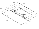
1 is a perspective view showing a configuration of a flow rate adjusting apparatus using a hinge according to a first embodiment of the present invention,
2 is a bottom perspective view showing the configuration of the first embodiment according to the present invention,
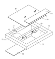
3 is an exploded perspective view showing a disassembled state of the first embodiment according to the present invention,
4 is an operational view showing the operating state of the open / close board of the first embodiment according to the present invention,
FIG. 5 is a sectional view showing a backflow prevention plate having a storage space expanded according to the first embodiment of the present invention, FIG.
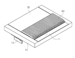
6 is a perspective view showing the configuration of a flow rate adjusting apparatus using a hinge according to the second embodiment of the present invention,
7 is a bottom perspective view showing a configuration of a second embodiment according to the present invention,
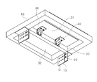
8 is an exploded perspective view showing a disassembled state of the second embodiment according to the present invention,
9 is an operational view showing a moving state of a reinforcing frame of a second embodiment according to the present invention,
10 is an operation diagram showing the operating state of the open / close board of the second embodiment according to the present invention.
While the present invention has been described in connection with certain exemplary embodiments, it is to be understood that the invention is not limited to the disclosed embodiments, but, on the contrary, is intended to cover various modifications and similarities. It should be understood, however, that the invention is not intended to be limited to the particular embodiments, but includes all modifications, equivalents, and alternatives falling within the spirit and scope of the invention.
In the following description of the present invention, detailed description of known related arts will be omitted when it is determined that the gist of the present invention may be unnecessarily obscured. In addition, numerals (e.g., first, second, etc.) used in the description of the present invention are merely an identifier for distinguishing one component from another.
Also, in this specification, when an element is referred to as being "coupled "," connected ", or "connected" with another element, the element is directly connected to the other element, Or may be directly bonded, but it should be understood that, unless otherwise specifically contradictory, there may be intervening, interlinked, or connected via another element in the middle.
Hereinafter, a flow rate adjusting apparatus using a hinge according to the present invention will be described in detail with reference to the accompanying drawings.
2 is a bottom perspective view showing a configuration of a first embodiment according to the present invention, and FIG. 3 is a cross-sectional view taken along the line II-II of FIG. FIG. 4 is a cross-sectional view of a check valve according to a first embodiment of the present invention, and FIG. 5 is a cross-sectional view of the expanded space of the first embodiment according to the present invention, Sectional view showing the backflow preventing plate.
As shown in FIGS. 1 to 4, the first embodiment relates to a flow rate adjusting device using a hinge capable of opening and closing the opening /
The first embodiment can increase the durability of the apparatus through the reinforcing
The flow control device using the hinge is mainly composed of three parts, that is, a
The frame 19 is installed at the upper end of the sewer well, and the sewer well is connected to the sewer pipe through a connecting pipe. The sewer pipe is connected to the sewage water treatment plant and is collected into the sewer.
The reinforcing
The reinforcing
Here, the opening /
Each of the
However, in the first embodiment, the distance between the rotary shaft and the opening and
In addition, the first embodiment can eliminate the rotation shaft and the bearing coupled to the conventional open / close plate, thereby reducing the installation value of the device and increasing the durability of the device.
A
The
Here, the
The
At this time, since the
In addition, the
The opening angle adjusting means is coupled to the reinforcing
4, when the
Also, since the
Accordingly, the opening angle adjusting means configured in the conventional "bar" or "wire" shape is simply formed in a bolt shape, so that the construction is convenient and the cost is reduced, so that the unit price can be decreased and the durability of the apparatus can be increased.
As shown in FIG. 5, the
In this embodiment, a partition wall (not shown) may be formed in the
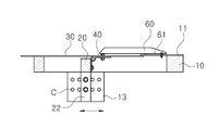
FIG. 6 is a perspective view showing a configuration of a flow rate adjusting apparatus using a hinge according to a second embodiment of the present invention, FIG. 7 is a bottom perspective view showing a configuration of a second embodiment according to the present invention, 9 is an explanatory view showing a moving state of the reinforcing frame of the second embodiment according to the present invention, and Fig. 10 is an exploded perspective view showing the opening and closing of the second embodiment according to the present invention Fig. 3 is an operation diagram showing the operating state of the plate.
As shown in FIGS. 6 to 10, in the flow rate control apparatus using the hinge of the second embodiment, the rotational center of the opening /
This is possible by obtaining the position of the reinforcing
To this end, the
At this time, the
The movement distance of the open /
Further, the
Here, the vertical fixing
The opening and closing
9 and 10, since the fixing
On the other hand, the upper surface of the fixing
The other side of the obstacle catching means 60 extends to the central region of the open /
10, by moving the position of the obstacle catching means 60 so that the other end of the obstacle catching means 60 is brought into contact with one surface of the opening and closing
This obstacle catching means 60 can control the opening angle of the opening and closing
It will be apparent to those skilled in the art that various modifications and variations can be made in the present invention without departing from the spirit or scope of the invention as defined by the appended claims. It's obvious that you can
10: frame 11: fixed plate 12: inlet
13: Horizontal fixed angle
20: reinforcing frame 21: knob bolt 22: vertical fixed angle
30: opening / closing plate 31: buoyancy cylinder 32: weight
40: HINGE
50: backflow prevention plate 51: storage space
60: Clogging means 61: Groove
D: water passage cross section C: joint ball
Claims (7)
A reinforcing frame (20) transversely to the frame (10); And
And an opening / closing plate (30) coupled to the reinforcing frame (20) through a plurality of hinges (40)
Each of the hinges 40 is coupled to a vertical surface of the reinforcing frame 20 and a bottom surface of the opening / closing plate so that the opening angle of the opening / closing plate can be opened /
Wherein a fixing plate (11) for forming an inlet (12) is connected to an upper portion of one side of the frame (10) with the opening / closing plate (30).
Characterized in that the reinforcing frame (20) is displaced in the longitudinal direction of the frame (10) so as to enable the central movement of the associated opening / closing plate (30).
Further comprising a horizontal fixed angle (13) in the form of "a" at the bottom of the frame (10)
The reinforcing frame 20 further includes vertical fixing angles 22 in the form of "I"
Wherein the frame (10) and the reinforcing frame (20) are bolted to each other through a vertical fixing angle (22) closely attached to the horizontal fixing angle (13).
A backflow prevention plate 50 for preventing reverse flow of rainwater is further provided between the other side of the frame 10 and the reinforcing frame 20,
Wherein the backflow prevention plate (50) forms a storage space (51).
Wherein the backflow prevention plate (50) is formed by expanding the storage space (51) by molding into a container form for sand dredging or tool storage.
The reinforcing frame 20 is further provided with a plurality of opening angle adjusting means for adjusting the opening angle of the opening / closing plate 30,
Wherein the opening angle adjusting means comprises a knob bolt (21) coupled to the reinforcing frame (20) so as to be exposed in the storage space (51).
A clogging means (60) is integrally coupled to the upper portion of the fixing plate (11)
The other side of the obstacle catching means 60 extends to a central region of the opening and closing plate 30 and is configured to adjust the opening angle of the opening and closing plate 30 by forming a groove 61 A flow control device using a hinge.
Priority Applications (1)
| Application Number | Priority Date | Filing Date | Title |
|---|---|---|---|
| KR1020170105738A KR102035387B1 (en) | 2017-08-21 | 2017-08-21 | Flow Control Devices Using Hinge |
Applications Claiming Priority (1)
| Application Number | Priority Date | Filing Date | Title |
|---|---|---|---|
| KR1020170105738A KR102035387B1 (en) | 2017-08-21 | 2017-08-21 | Flow Control Devices Using Hinge |
Publications (2)
| Publication Number | Publication Date |
|---|---|
| KR20170103718A true KR20170103718A (en) | 2017-09-13 |
| KR102035387B1 KR102035387B1 (en) | 2019-10-22 |
Family
ID=59968123
Family Applications (1)
| Application Number | Title | Priority Date | Filing Date |
|---|---|---|---|
| KR1020170105738A KR102035387B1 (en) | 2017-08-21 | 2017-08-21 | Flow Control Devices Using Hinge |
Country Status (1)
| Country | Link |
|---|---|
| KR (1) | KR102035387B1 (en) |
Citations (6)
| Publication number | Priority date | Publication date | Assignee | Title |
|---|---|---|---|---|
| KR20070026704A (en) * | 2007-01-18 | 2007-03-08 | 이경우 | Sewage in-draft control device having storm overflow chamber |
| KR101356852B1 (en) * | 2012-06-01 | 2014-01-28 | 진두남 | Apparatus for preventing from the inflow of sand and rain |
| KR101369130B1 (en) | 2013-03-29 | 2014-03-25 | 진두남 | Flow control device of sewage gathering duct with integrated checking hole |
| KR101453668B1 (en) | 2013-05-03 | 2014-10-22 | 전상훈 | Flow Control Device Of Sewage Gathering Duct |
| KR101533943B1 (en) * | 2015-01-15 | 2015-07-09 | 최지영 | A nonpower sand chamber Equipment adjusted rain of sewer pipe |
| KR101558325B1 (en) * | 2014-11-04 | 2015-10-13 | 광진구청 | Manhole for odor Blocker |
-
2017
- 2017-08-21 KR KR1020170105738A patent/KR102035387B1/en active IP Right Grant
Patent Citations (6)
| Publication number | Priority date | Publication date | Assignee | Title |
|---|---|---|---|---|
| KR20070026704A (en) * | 2007-01-18 | 2007-03-08 | 이경우 | Sewage in-draft control device having storm overflow chamber |
| KR101356852B1 (en) * | 2012-06-01 | 2014-01-28 | 진두남 | Apparatus for preventing from the inflow of sand and rain |
| KR101369130B1 (en) | 2013-03-29 | 2014-03-25 | 진두남 | Flow control device of sewage gathering duct with integrated checking hole |
| KR101453668B1 (en) | 2013-05-03 | 2014-10-22 | 전상훈 | Flow Control Device Of Sewage Gathering Duct |
| KR101558325B1 (en) * | 2014-11-04 | 2015-10-13 | 광진구청 | Manhole for odor Blocker |
| KR101533943B1 (en) * | 2015-01-15 | 2015-07-09 | 최지영 | A nonpower sand chamber Equipment adjusted rain of sewer pipe |
Also Published As
| Publication number | Publication date |
|---|---|
| KR102035387B1 (en) | 2019-10-22 |
Similar Documents
| Publication | Publication Date | Title |
|---|---|---|
| KR101146131B1 (en) | Using buoyancy for automatic closing pide door devices and method of control | |
| KR101106890B1 (en) | a Prevention apparatus of rain inflow for storm overflow chamber | |
| KR20170103718A (en) | Flow Control Devices Using Hinge | |
| KR20140022353A (en) | Opening and closing apparatus for storm overflow chamber | |
| KR100614912B1 (en) | Cover for drain | |
| JP4163246B2 (en) | Drainage | |
| KR100564921B1 (en) | Hume pipe connect manhole | |
| KR101356852B1 (en) | Apparatus for preventing from the inflow of sand and rain | |
| KR101132847B1 (en) | a Prevention apparatus of rain and sand inflow with a buoyancy chamber | |
| JP2016079661A (en) | Backflow prevention device for sewage basin | |
| KR100711853B1 (en) | Gathering drainage box of Earth and sand inflow Prevention apparatus | |
| KR100654402B1 (en) | Manhole having multitude structure | |
| KR200166989Y1 (en) | Auto opening and closing device of a room for exhaust rain water in a drainpipe | |
| KR101950599B1 (en) | A Device For Sewer Backflow Prevention | |
| JP5016665B2 (en) | Deodorizer for sewer pipes | |
| KR20170081374A (en) | floodgate apparatus for draining ground water | |
| JP6245699B2 (en) | Drainage equipment | |
| KR20110085088A (en) | A prevention apparatus of rain and sand inflow for a storm overflow chamber | |
| KR101564206B1 (en) | A flow control device with non-power eco-friendly | |
| KR20150124161A (en) | Flow control device of storm overflow chamber using buoyancy | |
| KR102143144B1 (en) | Water pipe changing device for sewer pipes | |
| CN215518887U (en) | Municipal drainage ditch inspection shaft lid with filter effect | |
| CN208685759U (en) | Prefabricated gutter | |
| KR200168154Y1 (en) | A backward flow preventing device for a drain-pipe | |
| KR200429801Y1 (en) | A stink trap for manholes |
Legal Events
| Date | Code | Title | Description |
|---|---|---|---|
| A201 | Request for examination | ||
| G15R | Request for early opening | ||
| E902 | Notification of reason for refusal | ||
| E701 | Decision to grant or registration of patent right | ||
| GRNT | Written decision to grant |