KR20170097302A - The structure of metal panel roof-truss supported by double purlin of assembling type - Google Patents
The structure of metal panel roof-truss supported by double purlin of assembling type Download PDFInfo
- Publication number
- KR20170097302A KR20170097302A KR1020160018877A KR20160018877A KR20170097302A KR 20170097302 A KR20170097302 A KR 20170097302A KR 1020160018877 A KR1020160018877 A KR 1020160018877A KR 20160018877 A KR20160018877 A KR 20160018877A KR 20170097302 A KR20170097302 A KR 20170097302A
- Authority
- KR
- South Korea
- Prior art keywords
- fastening
- plate
- support plate
- close contact
- shaped steel
- Prior art date
Links
Images


Classifications
-
- E—FIXED CONSTRUCTIONS
- E04—BUILDING
- E04D—ROOF COVERINGS; SKY-LIGHTS; GUTTERS; ROOF-WORKING TOOLS
- E04D3/00—Roof covering by making use of flat or curved slabs or stiff sheets
- E04D3/35—Roofing slabs or stiff sheets comprising two or more layers, e.g. for insulation
- E04D3/351—Roofing slabs or stiff sheets comprising two or more layers, e.g. for insulation at least one of the layers being composed of insulating material, e.g. fibre or foam material
-
- E—FIXED CONSTRUCTIONS
- E04—BUILDING
- E04B—GENERAL BUILDING CONSTRUCTIONS; WALLS, e.g. PARTITIONS; ROOFS; FLOORS; CEILINGS; INSULATION OR OTHER PROTECTION OF BUILDINGS
- E04B7/00—Roofs; Roof construction with regard to insulation
- E04B7/02—Roofs; Roof construction with regard to insulation with plane sloping surfaces, e.g. saddle roofs
- E04B7/022—Roofs; Roof construction with regard to insulation with plane sloping surfaces, e.g. saddle roofs consisting of a plurality of parallel similar trusses or portal frames
-
- E—FIXED CONSTRUCTIONS
- E04—BUILDING
- E04D—ROOF COVERINGS; SKY-LIGHTS; GUTTERS; ROOF-WORKING TOOLS
- E04D3/00—Roof covering by making use of flat or curved slabs or stiff sheets
- E04D3/36—Connecting; Fastening
- E04D3/3605—Connecting; Fastening of roof covering supported directly by the roof structure
Abstract
The present invention relates to a C-shaped section (10) having a plurality of C-shaped sections (10) spaced apart from each other and fixedly connected to a lower surface of a perforated panel (1) A second C-shaped steel (20) formed of a plurality of spaced-apart first and second C-shaped steels (10) and intersecting at right angles with each of the first C-shaped steels (10) A first coupling support plate 30 inserted into the first section steel 10; A second fastening support plate 40 inserted and positioned within the second C-shaped steel 20; A first through hole 52 corresponding to the second fastening hole 42 is formed on the upper side and a second through hole 56 is formed on the lower bent end 55 of the second fastening supporting plate 40, A ball support plate 50 which is in close contact with the support plate 50; The first fastening plate 61 is in close contact with one surface of the first fastening supporting plate 30 and is fastened to the second fastening plate 65 by a first fastening plate 61 and a second fastening plate 65 bent at right angles, (60) which is in close contact with one surface of the ball supporting plate (50); A first fastening bolt 72 for fastening the first fastening support plate 30 and the first fastening plate 61 and a second fastening bolt 72 for fastening the second fastening support plate 40, the ball support plate 50, And a second fastening bolt (76) for fastening the fastening bolt The present invention provides a metal panel roof-truss structure supported by an assembled dual purine comprising a plurality of metallic roof panels.
Description
The present invention relates to a metal panel roof-truss structure, and more particularly, to a metal panel roof-truss structure, which is easy to assemble and construct, and which is supported by a dual-purlin assembly capable of increasing the span width between purins while ensuring the structural stability of the roof. To a structure of a metal panel roof-truss.
A structure such as a ball truss roof in which a ball is placed in a plurality of defects in a truss roof or truss structure configured to distribute a load by connecting linear members can be easily constructed with a large space without an intermediate column The structure can be reduced in weight, and furthermore, since the minimum grid of the structure is small, the secondary member can be omitted.
Conventionally, a ball truss metal panel roof is constructed by installing a ball truss as shown in FIG. 5 on a metal panel roof having a structure as shown in FIG. As shown in the drawings, the conventional metal panel roof comprises a C-
The ball truss includes a
That is, in the conventional ball truss metal panel roof, the Z bar provided on the upper part of the perforated panel supports the roof panel, and the C-shaped steel located below the perforated panel supports the metal panel roof and supports the ball truss. Therefore, when the overall size of the roof structure or the size of the supported ball truss is increased, it is necessary to use a thicker C-shaped steel or to narrow the span width between the C-shaped steel. However, in the former case, there is a problem of increasing the total construction cost, and the latter is a problem of increasing the construction cost and the construction period.
In order to solve these various problems, C-shaped steel having a predetermined thickness is vertically cross-disposed, and the C-shaped cross-shaped upper and lower C-shaped steel are combined with each other by welding. However, in the case of joining the C-shaped steel beams crossing the upper and lower portions by welding, there is a problem that the bonding strength of the welded portion is significantly reduced as the welded portion naturally corrodes when a predetermined time has elapsed after completion of the construction. In addition, if rainwater penetrates through the roof panel, the corrosion of the welded part becomes worse and there is a structural problem that the rust caused by the corrosion falls into the building.
It is an object of the present invention to provide a metal panel roof-truss structure which is simple in construction and excellent in structural stability, and is capable of expanding a span width between perlin.
In order to achieve the above object, the present invention provides a heat exchanger comprising a perforated panel (1), a heat insulating material (2) positioned on the upper surface of the perforated panel (1), a metal panel roof (4) A metal panel roof-truss structure comprising a plurality of balls (6) spaced a certain distance below a panel (1) and members (7) connecting adjacent balls (6) A plurality of C-shaped sections (10) spaced apart from each other and fixedly coupled to the lower surface of the perforated panel (1); A second C-shaped steel (20) formed of a plurality of spaced-apart first and second C-shaped steels (10) and intersecting at right angles with each of the first C-shaped steels (10) A first
The first
At this time, each of the first and second
The present invention proposes a construction for assembling a fastening plate by using fastening bolts in a state where first and second C-shaped steel bars as purlin which support a roof panel and a truss are arranged in an alternately arranged upper and lower double, It is possible to provide a structurally very stable metal panel roof-truss structure even when the span width is extended as well as the assembly and the construction are very convenient as compared with the conventional art.
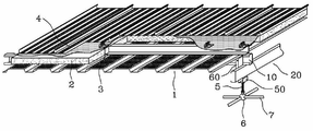
BRIEF DESCRIPTION OF THE DRAWINGS Figure 1 is a schematic overall configuration of a metal panel roof-truss structure according to the present invention;
Figure 2 is a schematic coupling configuration of a furlin in a metal panel roof-truss structure according to the present invention;
3 is a schematic other schematic view of a furnace in a metal panel roof-truss structure according to the present invention.
Fig. 4 is a schematic coupling configuration of a conventional metal panel roof; Fig.
Fig. 5 is a schematic view showing a coupling structure between a purlin and a ball truss.
DETAILED DESCRIPTION OF THE PREFERRED EMBODIMENTS Preferred embodiments of the present invention will now be described in detail with reference to the accompanying drawings. However, the present invention is not limited to the technical features of the present invention, A detailed description thereof will be omitted.
Fig. 1 shows a schematic overall configuration of a metal panel roof-truss structure as an example according to the present invention, and Fig. 2 shows a schematic coupling configuration diagram of a furnace in Fig. As shown in the drawing, the present invention is characterized by comprising a
The perforated
The
The
Purine is a means for supporting a roof and a ball truss, and the present invention proposes a purine structure having first and second C shapes as shown in the drawing. The first C-shaped steel (10) as the first purlin is made of a plurality of spaced apart mutually spaced apart and positioned on the lower surface of the perforated panel (1). The first C-shaped steel is tightly fixedly coupled to the
The second C-
The first fastening supporting
On the other hand, the present invention does not exclude the case where the first
The second
It is not excluded that the second fastening supporting
On the other hand, the present invention does not exclude the case where the first and second
The
If the first and second
The
If the first and second
The fastening bolts are means for integrating the first and second
The
One end portion of the
On the other hand, the present invention does not exclude the case where a simple truss structure is provided, unlike the case where the above-described ball truss structure is provided under the first and second C-shaped sections as purlin. The simple truss structure is a structure in which the linear members are coupled with each other at an angle without mediating the ball. When the simple truss structure is provided, the other end portion of the adjustment bolt can be coupled to the defect portion where the linear members in the truss structure are interconnected. Such a coupling structure is widely known in the related art, and a detailed description thereof will be omitted.
As described above, the present invention is capable of supporting the roof and the ball truss structure by vertically crossing the first and second C-shaped steel pipes as the purlin, and thus the structural stability of the building can be secured even if the span width is expanded. In which the first and second C-shaped sections are integrally assembled as a fastening bolt without performing a separate welding operation, there is an advantage that the work on the site can be greatly simplified.
While the present invention has been particularly shown and described with reference to exemplary embodiments thereof, it is to be understood that the invention is not limited to the disclosed embodiments, but, on the contrary, is intended to cover various modifications and equivalent arrangements included within the spirit and scope of the appended claims. It will be apparent that the present invention can be practiced with added features.
10: first C-shaped steel 20: second C-shaped steel
30: first fastening supporting plate 40: second fastening supporting plate
50: ball support plate 60: fastening plate
72, 76: first and second fastening bolts
Claims (3)
A plurality of C-shaped sections (10) spaced apart from each other by a predetermined distance and fixedly connected to the lower surface of the perforated panel (1);
A second C-shaped steel (20) formed of a plurality of spaced-apart first and second C-shaped steels (10) and intersecting at right angles with each of the first C-shaped steels (10)
A first clamping support plate 30 inserted into the first section 10 of the first and second C-shaped sections 10 and 20 formed by the first clamping holes 32 and intersecting at right angles;
A second fastening support plate 40 inserted and positioned in the second C-shaped steel 20 among the first and second C-shaped steels 10 and 20 formed with the second fastening holes 42 and intersecting at right angles;
A first through hole 52 corresponding to the second fastening hole 42 is formed on the upper side and an adjusting bolt 52 connected to the ball 6 on the lower bent end 55 for adjusting the position of the ball 6, (50) formed with a second through hole (56) through which one end portion of the second fastening support plate (5) is inserted and fixed, and is in close contact with one surface of the second fastening support plate (40);
The first and second fastening plates 61 and 65 are provided with a first fastening plate 61 and a second fastening plate 65 bent at right angles, The first fastening plate 61 is brought into close contact with one surface of the first fastening supporting plate 30 and the second fastening plate 65 is brought into close contact with the one surface of the first fastening supporting plate 30, (60) which is in close contact with one surface of the base (50);
A first fastening bolt 72 for fastening the first fastening support plate 30 and the first fastening plate 61 and a second fastening bolt 72 for fastening the second fastening support plate 40, the ball support plate 50, And a second fastening bolt (76) for fastening the fastening bolt
A metal panel roof-truss structure supported by an assembled duplex furnace comprising:
The first fastening support plate 30 includes a first fastening plate 31 whose upper and lower portions are in close contact with the step 12 of the opening of the first C-shaped steel 10 and a second fastening plate 31 whose edge is formed on the inner surface of the first C- And the first fastening support plate 30 has a second fastening plate 41 which is in close contact with the step 22 of the opening of the second C-shaped steel 20, And a second bent end (45) whose edge portion is in close contact with the inner surface of the second C-shaped steel (10).
A metal panel roof-truss structure supported by a double purlin in an assembled manner, characterized in that each of the first and second fastening support plates (30, 40) is divided into a plurality of pieces.
Priority Applications (1)
| Application Number | Priority Date | Filing Date | Title |
|---|---|---|---|
| KR1020160018877A KR101864681B1 (en) | 2016-02-18 | 2016-02-18 | The structure of metal panel roof-truss supported by double purlin of assembling type |
Applications Claiming Priority (1)
| Application Number | Priority Date | Filing Date | Title |
|---|---|---|---|
| KR1020160018877A KR101864681B1 (en) | 2016-02-18 | 2016-02-18 | The structure of metal panel roof-truss supported by double purlin of assembling type |
Publications (2)
| Publication Number | Publication Date |
|---|---|
| KR20170097302A true KR20170097302A (en) | 2017-08-28 |
| KR101864681B1 KR101864681B1 (en) | 2018-06-05 |
Family
ID=59759905
Family Applications (1)
| Application Number | Title | Priority Date | Filing Date |
|---|---|---|---|
| KR1020160018877A KR101864681B1 (en) | 2016-02-18 | 2016-02-18 | The structure of metal panel roof-truss supported by double purlin of assembling type |
Country Status (1)
| Country | Link |
|---|---|
| KR (1) | KR101864681B1 (en) |
Cited By (2)
| Publication number | Priority date | Publication date | Assignee | Title |
|---|---|---|---|---|
| CN114396124A (en) * | 2022-01-21 | 2022-04-26 | 陈智利 | Connecting method for roof beam of sunlight room |
| KR102448360B1 (en) | 2021-11-25 | 2022-09-28 | 주식회사 디자인기린 | Purlin with earthquake resistant of sliding type |
Families Citing this family (1)
| Publication number | Priority date | Publication date | Assignee | Title |
|---|---|---|---|---|
| KR102502043B1 (en) * | 2020-02-11 | 2023-02-21 | 주식회사 광스틸 | Building structure using bracket module and construction method using thereof |
Citations (6)
| Publication number | Priority date | Publication date | Assignee | Title |
|---|---|---|---|---|
| KR820000582Y1 (en) | 1977-11-01 | 1982-04-09 | 요시다 다다오 | Slope-changeable roof construction |
| JPH0657867A (en) * | 1993-06-29 | 1994-03-01 | Y K K Architect Prod Kk | Coupling device |
| JP3044896U (en) * | 1997-06-30 | 1998-01-16 | 文男 川阪 | Connection structure of C-shaped steel |
| KR101399375B1 (en) | 2013-09-16 | 2014-05-27 | 주식회사 케이에스테크 | Space frame with virtical bracket |
| KR101414521B1 (en) * | 2013-11-18 | 2014-07-04 | 한국아치스판 주식회사 | Panel assembly of roof |
| KR101444454B1 (en) | 2014-04-02 | 2014-10-02 | 스카이패널 주식회사 | Panel assembly of roof having a reinforcement bracket |
-
2016
- 2016-02-18 KR KR1020160018877A patent/KR101864681B1/en active IP Right Grant
Patent Citations (6)
| Publication number | Priority date | Publication date | Assignee | Title |
|---|---|---|---|---|
| KR820000582Y1 (en) | 1977-11-01 | 1982-04-09 | 요시다 다다오 | Slope-changeable roof construction |
| JPH0657867A (en) * | 1993-06-29 | 1994-03-01 | Y K K Architect Prod Kk | Coupling device |
| JP3044896U (en) * | 1997-06-30 | 1998-01-16 | 文男 川阪 | Connection structure of C-shaped steel |
| KR101399375B1 (en) | 2013-09-16 | 2014-05-27 | 주식회사 케이에스테크 | Space frame with virtical bracket |
| KR101414521B1 (en) * | 2013-11-18 | 2014-07-04 | 한국아치스판 주식회사 | Panel assembly of roof |
| KR101444454B1 (en) | 2014-04-02 | 2014-10-02 | 스카이패널 주식회사 | Panel assembly of roof having a reinforcement bracket |
Cited By (3)
| Publication number | Priority date | Publication date | Assignee | Title |
|---|---|---|---|---|
| KR102448360B1 (en) | 2021-11-25 | 2022-09-28 | 주식회사 디자인기린 | Purlin with earthquake resistant of sliding type |
| CN114396124A (en) * | 2022-01-21 | 2022-04-26 | 陈智利 | Connecting method for roof beam of sunlight room |
| CN114396124B (en) * | 2022-01-21 | 2023-07-11 | 陈智利 | Connection method for roof beam of sunlight house |
Also Published As
| Publication number | Publication date |
|---|---|
| KR101864681B1 (en) | 2018-06-05 |
Similar Documents
| Publication | Publication Date | Title |
|---|---|---|
| KR101864681B1 (en) | The structure of metal panel roof-truss supported by double purlin of assembling type | |
| JP2011518265A (en) | BUILDING STRUCTURE COMPONENT AND MANUFACTURING METHOD THEREOF | |
| KR101601913B1 (en) | Z-bar assembly for roof panel | |
| KR101465013B1 (en) | Truss type roof structure and installation method thereof | |
| JP6150640B2 (en) | Solar panel mount | |
| KR100732562B1 (en) | Panel structure of roof | |
| KR200390559Y1 (en) | purlin, clip for purlin and roof structure using these | |
| KR100910163B1 (en) | Bracket for fixing curtain wall | |
| JP6079464B2 (en) | Bearing walls and houses | |
| JP2015055038A (en) | Rigid-frame of building | |
| KR101738244B1 (en) | Built-up beam having truss reinforcement | |
| CN211447287U (en) | Building steel structure convenient to assembly | |
| CN104695598A (en) | Horizontal frame and vertical frame connection structure of T-shaped steel joist | |
| JP3156192U (en) | Ceiling board support structure | |
| KR100912552B1 (en) | Construction triangular pipe of prefabricated connecting structure | |
| KR200430415Y1 (en) | Partition wall | |
| JP2002021242A (en) | Staging installing structure | |
| KR20180086640A (en) | Structure of metallic roof panel | |
| JP5953213B2 (en) | Building with balcony | |
| KR200468935Y1 (en) | Roof structure with solar cell module panel | |
| CN219471313U (en) | Plate beam connecting structure for mutually overlapping assembled integral concrete sandwich plates | |
| KR101371198B1 (en) | Square pipe type assembling structural member | |
| KR100766301B1 (en) | Structure for connecting horizontal beam to h type beam | |
| RU67125U1 (en) | FRAMELESS FRAME BUILDING | |
| JP2019049169A (en) | Building unit and unit type building |
Legal Events
| Date | Code | Title | Description |
|---|---|---|---|
| A201 | Request for examination | ||
| E701 | Decision to grant or registration of patent right | ||
| GRNT | Written decision to grant |