KR20170089634A - Industrial washer - Google Patents
Industrial washer Download PDFInfo
- Publication number
- KR20170089634A KR20170089634A KR1020160010081A KR20160010081A KR20170089634A KR 20170089634 A KR20170089634 A KR 20170089634A KR 1020160010081 A KR1020160010081 A KR 1020160010081A KR 20160010081 A KR20160010081 A KR 20160010081A KR 20170089634 A KR20170089634 A KR 20170089634A
- Authority
- KR
- South Korea
- Prior art keywords
- cleaning
- workpiece
- tank
- washing tank
- cleaning chamber
- Prior art date
Links
Images

Classifications
-
- B—PERFORMING OPERATIONS; TRANSPORTING
- B08—CLEANING
- B08B—CLEANING IN GENERAL; PREVENTION OF FOULING IN GENERAL
- B08B1/00—Cleaning by methods involving the use of tools, brushes, or analogous members
- B08B1/02—Cleaning travelling work, e.g. a web, articles on a conveyor
-
- B—PERFORMING OPERATIONS; TRANSPORTING
- B08—CLEANING
- B08B—CLEANING IN GENERAL; PREVENTION OF FOULING IN GENERAL
- B08B3/00—Cleaning by methods involving the use or presence of liquid or steam
- B08B3/02—Cleaning by the force of jets or sprays
-
- B—PERFORMING OPERATIONS; TRANSPORTING
- B08—CLEANING
- B08B—CLEANING IN GENERAL; PREVENTION OF FOULING IN GENERAL
- B08B3/00—Cleaning by methods involving the use or presence of liquid or steam
- B08B3/04—Cleaning involving contact with liquid
- B08B3/041—Cleaning travelling work
-
- B—PERFORMING OPERATIONS; TRANSPORTING
- B08—CLEANING
- B08B—CLEANING IN GENERAL; PREVENTION OF FOULING IN GENERAL
- B08B3/00—Cleaning by methods involving the use or presence of liquid or steam
- B08B3/04—Cleaning involving contact with liquid
- B08B3/10—Cleaning involving contact with liquid with additional treatment of the liquid or of the object being cleaned, e.g. by heat, by electricity or by vibration
- B08B3/102—Cleaning involving contact with liquid with additional treatment of the liquid or of the object being cleaned, e.g. by heat, by electricity or by vibration with means for agitating the liquid
-
- B—PERFORMING OPERATIONS; TRANSPORTING
- B08—CLEANING
- B08B—CLEANING IN GENERAL; PREVENTION OF FOULING IN GENERAL
- B08B5/00—Cleaning by methods involving the use of air flow or gas flow
- B08B5/02—Cleaning by the force of jets, e.g. blowing-out cavities
-
- B—PERFORMING OPERATIONS; TRANSPORTING
- B22—CASTING; POWDER METALLURGY
- B22D—CASTING OF METALS; CASTING OF OTHER SUBSTANCES BY THE SAME PROCESSES OR DEVICES
- B22D31/00—Cutting-off surplus material, e.g. gates; Cleaning and working on castings
- B22D31/002—Cleaning, working on castings
Abstract
The present invention relates to an industrial cleaning apparatus, and is characterized in that it is possible to improve the efficiency of cleaning by washing the cleaning liquid twice.
The cleaning apparatus includes: a cleaning tank having an open top and a cleaner outlet at a bottom; A motor for rotating the washing tank at a lower portion of the washing tank; A jet cleaning chamber having an open top and a plurality of nozzles on an inner surface thereof; And a hanger rod for hanging the workpiece, and conveying means for conveying the workpiece into the washing tank and the spray cleaning chamber.
Description
BACKGROUND OF THE
Since the surface of the workpiece after the casting is precision machined is adhered with foreign materials such as machining oil and machined chips, it is necessary to carry out a cleaning process on the workpiece in order to remove it.
In order to improve the efficiency of the cleaning of the workpiece, the cleaning agent must be sprayed at a high pressure on the surface of the workpiece. In the past, since the workpiece cleaning work was manually performed by the operator, the fine cleaning oil generated by spraying the cleaning agent lowers the safety of the worker there was.
For this reason, techniques have been developed for automatic cleaning of workpieces, and the 'chalk cleaner' of Publication No. 20-1997-0004467 is one such technique. The 'chalk cleaner' can automatically clean the workpiece through the
However, it is not easy to clean the workpiece to the corner of the workpiece through the
It is an object of the present invention to provide an industrial cleaning device capable of cleaning a workpiece in a second manner by different methods, thereby improving the cleaning power.
According to a preferred embodiment of the present invention, there is provided a cleaning apparatus for removing foreign matter on a surface of a workpiece, the cleaning apparatus comprising: a cleaning tank having an upper opening and a lower opening; A motor for rotating the washing tank at a lower portion of the washing tank; A jet cleaning chamber having an open top and a plurality of nozzles on an inner surface thereof; And a hanger rod for suspending the workpiece, and conveying means for conveying the workpiece into the washing tank and the spray cleaning chamber.
According to another embodiment of the present invention, there is provided an industrial cleaning apparatus characterized in that a plurality of projections are formed along the inner surface of the cleaning tank.
According to another embodiment of the present invention, an industrial cleaning apparatus is provided, wherein the lower end of the cleaning tank is of a hopper type.
According to still another embodiment of the present invention, the lid is formed on the upper surface of the washing tank, the lid being divided into a plurality of pieces, the through-hole passing through the hanger rod of the transfer means, Is provided.
According to another embodiment of the present invention, the conveying means is provided with a cushioning member for cushioning an impact applied to the hanger rod.
According to another embodiment of the present invention, there is provided an industrial cleaning apparatus characterized by further comprising a second motor for rotating the jet cleaning chamber at a lower portion of the jet cleaning chamber.
Industrial cleaning apparatuses according to the present invention clean a workpiece twice in a cleaning tank capable of being cleaned to every corner of the workpiece and in a spray cleaning chamber capable of removing foreign materials stuck firmly to the surface of the workpiece, Excellent cleaning effect.
When the lower end of the washing tank is of the hopper type, only the foreign substances contained in the washing agent in the washing tank can be removed at any time, so that the amount of the washing agent used can be reduced.
When the conveying means constituting the cleaning apparatus is provided with the buffer member, it is possible to prevent the workpiece or the conveying means from being damaged by the pressure of the cleaning agent.
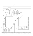
1 is a schematic cross-sectional view of an industrial cleaning apparatus according to the present invention.
2 is an explanatory view of a process of cleaning a workpiece using the cleaning apparatus.
Hereinafter, specific embodiments of the present invention will be described in detail with reference to the drawings.
BACKGROUND OF THE
An
The
The
The
The transfer means 40 serves to transfer the workpiece W into the
The
The process of washing the workpiece W through the
When the workpiece is firstly cleaned in the
In the step b), the
Since the secondary cleaning process in the
The cleaning
A plurality of
The cleaning agent in the
The lower end of the
As described above, when the cleaning operation is repeated for the workpiece in the
When the lower end of the
A
The
The
The conveying means (40) may further comprise a buffer member (42) for buffering an impact applied to the hanger rod (41).
In order for the cleaning agent sprayed in the
The
The
The
Since the
The
The
While the invention has been shown and described with reference to certain preferred embodiments thereof, it will be understood by those skilled in the art that various changes in form and details may be made therein without departing from the spirit and scope of the invention as defined by the appended claims. And thus fall within the scope of the present invention.
1: Industrial cleaning device 10: Cleaning tank
11: Cleanser outlet port 12:
13:
20: motor 30: injection cleaning chamber
31: Nozzle 40: Feeding means
41: hanger rod 42: buffer member
50: second motor
Claims (6)
A cleaning tank (10) having an open top and a cleanser outlet (11) at its bottom end;
A motor 20 for rotating the washing tank 10 at a lower portion of the washing tank 10;
An injection cleaning chamber 30 having a top open box shape and having a plurality of nozzles 31 on its inner side; And
And a transfer means (40) having a hanger rod (41) for suspending the workpiece and carrying the workpiece into the cleaning tank (10) and the spray cleaning chamber (30).
And a plurality of protrusions (12) are formed along the inner surface of the washing tank (10).
Characterized in that the lower end of the washing tank (10) is of the hopper type.
A lid 13 having a through hole 13a through which the hanger rod 41 of the conveying means 40 passes is disposed in the center of the washing tank 10, .
Characterized in that the conveying means (40) comprises a buffer member (42) for buffering an impact applied to the hanger rod (41).
Further comprising a second motor (50) for rotating the spray cleaning chamber (30) at a lower portion of the spray cleaning chamber (30).
Priority Applications (1)
| Application Number | Priority Date | Filing Date | Title |
|---|---|---|---|
| KR1020160010081A KR20170089634A (en) | 2016-01-27 | 2016-01-27 | Industrial washer |
Applications Claiming Priority (1)
| Application Number | Priority Date | Filing Date | Title |
|---|---|---|---|
| KR1020160010081A KR20170089634A (en) | 2016-01-27 | 2016-01-27 | Industrial washer |
Publications (1)
| Publication Number | Publication Date |
|---|---|
| KR20170089634A true KR20170089634A (en) | 2017-08-04 |
Family
ID=59654612
Family Applications (1)
| Application Number | Title | Priority Date | Filing Date |
|---|---|---|---|
| KR1020160010081A KR20170089634A (en) | 2016-01-27 | 2016-01-27 | Industrial washer |
Country Status (1)
| Country | Link |
|---|---|
| KR (1) | KR20170089634A (en) |
Cited By (2)
| Publication number | Priority date | Publication date | Assignee | Title |
|---|---|---|---|---|
| CN112846155A (en) * | 2021-01-08 | 2021-05-28 | 南京琮咀科技发展有限公司 | Casting forming process for aluminum alloy end cover of pump body |
| CN114192762A (en) * | 2021-12-06 | 2022-03-18 | 贵溪骏达特种铜材有限公司 | A belt cleaning device for special type copper product foundry goods |
-
2016
- 2016-01-27 KR KR1020160010081A patent/KR20170089634A/en not_active Application Discontinuation
Cited By (2)
| Publication number | Priority date | Publication date | Assignee | Title |
|---|---|---|---|---|
| CN112846155A (en) * | 2021-01-08 | 2021-05-28 | 南京琮咀科技发展有限公司 | Casting forming process for aluminum alloy end cover of pump body |
| CN114192762A (en) * | 2021-12-06 | 2022-03-18 | 贵溪骏达特种铜材有限公司 | A belt cleaning device for special type copper product foundry goods |
Similar Documents
| Publication | Publication Date | Title |
|---|---|---|
| KR101299659B1 (en) | Turret-type cleaning apparatus | |
| CN110788091B (en) | Device and method for cleaning inner wall of food-grade steel pipe | |
| KR101215193B1 (en) | Rotary washing device for automotive v type engine cylinder block using coolant spray and air blow | |
| CN204035145U (en) | A kind of bottle washer for veterinary drug bottle | |
| KR20170089634A (en) | Industrial washer | |
| CN205032430U (en) | Spare part washs device and it should to use device for refabrication | |
| JP2011078929A (en) | Cleaning device for bucket or the like | |
| JP5588768B2 (en) | Shock absorber cleaning device, cleaning method and manufacturing method | |
| JP5175971B1 (en) | Cutting parts cleaning equipment | |
| KR101700510B1 (en) | Wet sandblasting cleaning device and method | |
| CA2112455A1 (en) | Method and Apparatus for Washing and Cleaning a Workpiece | |
| JP2010274245A (en) | Washing apparatus, drying apparatus, and washing system | |
| KR101113272B1 (en) | Filter cleaner | |
| KR101904645B1 (en) | Industrial cleaner apparatus | |
| JP5744428B2 (en) | Cleaning device | |
| IE86311B1 (en) | A cylinder handling and cleaning system | |
| CN210333502U (en) | Screw surface greasy dirt remove device | |
| KR20170115673A (en) | a apparatus polishing surface of machine part processing and method using the apparatus | |
| KR101434650B1 (en) | Cleaning device using sand-jet | |
| JP3188438B2 (en) | Cleaning equipment for cylindrical workpieces | |
| CN219646842U (en) | Filter equipment is used in cleaner filling | |
| JP4117410B2 (en) | Cleaning device | |
| CN212824416U (en) | Engine balancer housing cleaning equipment | |
| CN220049343U (en) | Bottle flushing machine | |
| CN213386433U (en) | Belt cleaning device for pneumatic ash conveying |
Legal Events
| Date | Code | Title | Description |
|---|---|---|---|
| A201 | Request for examination | ||
| E902 | Notification of reason for refusal | ||
| E902 | Notification of reason for refusal | ||
| E601 | Decision to refuse application |