KR20170088621A - Explosion-proof tunnel using corrugated steel plate - Google Patents
Explosion-proof tunnel using corrugated steel plate Download PDFInfo
- Publication number
- KR20170088621A KR20170088621A KR1020160008730A KR20160008730A KR20170088621A KR 20170088621 A KR20170088621 A KR 20170088621A KR 1020160008730 A KR1020160008730 A KR 1020160008730A KR 20160008730 A KR20160008730 A KR 20160008730A KR 20170088621 A KR20170088621 A KR 20170088621A
- Authority
- KR
- South Korea
- Prior art keywords
- plate
- steel plate
- wall
- corrugated steel
- cover
- Prior art date
Links
- 229910000831 Steel Inorganic materials 0.000 title claims abstract description 50
- 239000010959 steel Substances 0.000 title claims abstract description 50
- 238000004880 explosion Methods 0.000 claims abstract description 11
- 230000003014 reinforcing effect Effects 0.000 claims description 13
- 238000000034 method Methods 0.000 claims description 9
- 239000004567 concrete Substances 0.000 claims description 7
- 230000008878 coupling Effects 0.000 claims description 5
- 238000010168 coupling process Methods 0.000 claims description 5
- 238000005859 coupling reaction Methods 0.000 claims description 5
- 239000002184 metal Substances 0.000 claims 4
- 238000010276 construction Methods 0.000 abstract description 6
- 230000000694 effects Effects 0.000 description 3
- 239000002360 explosive Substances 0.000 description 3
- 238000009434 installation Methods 0.000 description 3
- 230000009467 reduction Effects 0.000 description 3
- 238000011161 development Methods 0.000 description 2
- 238000013461 design Methods 0.000 description 1
- 230000006872 improvement Effects 0.000 description 1
- 239000000463 material Substances 0.000 description 1
- 238000012986 modification Methods 0.000 description 1
- 230000004048 modification Effects 0.000 description 1
- 239000011150 reinforced concrete Substances 0.000 description 1
- 238000011160 research Methods 0.000 description 1
Images


Classifications
-
- F—MECHANICAL ENGINEERING; LIGHTING; HEATING; WEAPONS; BLASTING
- F42—AMMUNITION; BLASTING
- F42D—BLASTING
- F42D5/00—Safety arrangements
-
- E—FIXED CONSTRUCTIONS
- E02—HYDRAULIC ENGINEERING; FOUNDATIONS; SOIL SHIFTING
- E02D—FOUNDATIONS; EXCAVATIONS; EMBANKMENTS; UNDERGROUND OR UNDERWATER STRUCTURES
- E02D27/00—Foundations as substructures
- E02D27/01—Flat foundations
- E02D27/016—Flat foundations made mainly from prefabricated concrete elements
-
- E—FIXED CONSTRUCTIONS
- E02—HYDRAULIC ENGINEERING; FOUNDATIONS; SOIL SHIFTING
- E02D—FOUNDATIONS; EXCAVATIONS; EMBANKMENTS; UNDERGROUND OR UNDERWATER STRUCTURES
- E02D27/00—Foundations as substructures
- E02D27/32—Foundations for special purposes
Landscapes
- Engineering & Computer Science (AREA)
- General Engineering & Computer Science (AREA)
- Life Sciences & Earth Sciences (AREA)
- General Life Sciences & Earth Sciences (AREA)
- Mining & Mineral Resources (AREA)
- Paleontology (AREA)
- Civil Engineering (AREA)
- Structural Engineering (AREA)
- Lining And Supports For Tunnels (AREA)
- Refuge Islands, Traffic Blockers, Or Guard Fence (AREA)
Abstract
Description
본 발명은 건설 분야에 관한 것으로서, 상세하게는 파형강판을 이용한 방폭터널에 관한 것이다.Field of the Invention [0002] The present invention relates to a construction field, and more particularly, to an explosion-proof tunnel using a corrugated steel plate.
방폭터널이란, 탄약고와 같이 폭발사고의 우려가 있는 위험시설의 주위를 운행하는 차량을 보호하기 위하여, 도로의 외부를 덮어 보호하도록 설치되는 지상터널 구조물을 말한다.An explosion-proof tunnel is a ground tunnel structure that is installed to cover the outside of a road to protect a vehicle that runs around a dangerous facility such as an ammunition.
종래에는 철근 콘크리트 구조로서 이러한 방폭터널을 시공하였는데, 이는 시공기간 및 비용이 과도하게 소요된다는 점, 폭발사고로부터 내부 차량을 보호하는 목적에 비추어 과도한 방호구조이므로 효율적이지 못하다는 점 등의 문제가 지적되어 왔다.Conventionally, this type of explosion-proof tunnel was constructed as a reinforced concrete structure because it is inefficient due to an excessive protection structure in view of an excessive construction time and cost, and an object of protecting an internal vehicle from an explosion accident Has come.
폭발물 저장에 따른 안전성 중에서 가장 중요한 내용은 저장 폭약량에 따른 ‘안전거리(Safety Quantity-Distance)’의 확보에 관한 사항으로 이는 각종 규정에 의해 엄격하게 관리되고 있어 탄약저장 안전성을 확보하고 있다.The most important aspect of the safety due to the storage of explosives is the securing of the "Safety Quantity-Distance" according to the amount of storage explosive, which is strictly controlled by various regulations, thus ensuring ammunition storage safety.
그러나 최근 들어 이 기준내용의 경직성 문제나 우리 현실에 맞는 탄약 저장방안, 안전거리 감소방안 요구 등의 적용성 개선문제가 대두되어 저장시설(탄약고)의 개선, 폭약량 제한, 저장방식의 개선, 폭발에 의한 폭발효과 저감시설 개발 및 공로거리 감소방안 등, 한국 실정에 맞는 폭발물 및 탄약 저장시설 개발 및 그에 따른 안전거리 감소를 위한 연구가 필요한 실정이다.In recent years, however, there has been a problem of improving the applicability of the amendment of the standard contents, the ammunition storage method and the reduction of the safety distance according to our reality. As a result, improvement of storage facilities (ammunition) The development of facilities to reduce the explosion effect and the reduction of the distance of merit are required for the development of explosives and ammunition storage facilities in Korea.
본 발명은 상기와 같은 문제점을 해결하기 위하여 도출된 것으로서, 시공기간 및 비용을 줄이면서도, 효율적으로 폭발사고로부터 내부 차량을 보호하도록 하는 파형강판을 이용한 방폭터널을 제시하는 것을 그 목적으로 한다.It is an object of the present invention to provide an explosion-proof tunnel using a corrugated steel plate for efficiently protecting an internal vehicle from an explosion accident while reducing construction time and cost.
즉, 기존의 공로안전거리(500,000lbs-800m)를 대폭 감소시켜 주요한 신설도로의 계획 및 설치를 용이하게 하고자 한다.In other words, the existing safety clearance distance (500,000 lbs-800 m) is greatly reduced to facilitate the planning and installation of major new roads.
안전거리 중에서 공로거리의 제한을 받는 경우에 불가피한 도로설치를 위한 안전거리 감소시설로 기존의 방음벽 또는 방음터널과 비슷한 개념으로 방음시설의 경우 설계하중은 풍압이 되나, 방폭시설의 경우에는 폭발압력이 된다.It is a safety distance reduction facility for road installation which is inevitable when the distance of safety is restricted in case of limitation of the safety distance. In a similar concept to the existing soundproof wall or soundproof tunnel, the design load becomes wind pressure in the case of soundproofing. do.
현재 방음의 목적으로 도로에 설치되고 있는 방음벽 및 방음터널의 구조를 이용하여 공로에 도달하는 폭발압력 저감의 용도로 활용이 가능한 파형강판을 이용한 터널형태 방폭시설을 제시하는 것을 목적으로 한다.It is an object of the present invention to provide a tunnel type explosion proofing facility using a corrugated steel sheet which can be utilized for the purpose of reducing the explosion pressure reaching the merit by using the structure of the soundproof wall and the soundproof tunnel installed on the road for the purpose of soundproofing.
상기 과제의 해결을 위하여, 본 발명은 내부의 도로를 통해 운행하는 차량을 주위의 폭발사고로부터 보호하기 위한 방폭터널에 있어서, 다수가 상호 간격을 두고 상하방향을 따라 이열로 설치된 지주부(100); 종단면이 파형을 이루도록, 다수의 파형강판(10)의 조립에 의해 벽체 구조로 형성됨과 아울러, 상기 지주부(100) 사이에 설치된 벽체부(200); 횡단면이 파형을 이루도록, 다수의 파형강판(10)의 조립에 의해 아치형 구조로 형성됨과 아울러, 상기 이열의 벽체부(200)의 상부를 덮도록 설치된 천정부(300);를 포함하는 것을 특징으로 하는 파형강판을 이용한 방폭터널을 제시한다.In order to solve the above problems, the present invention provides an explosion-proof tunnel for protecting a vehicle running through an internal road from an explosion in the surrounding, ; A
상기 지주부(100)는, 길이방향을 따라 지반에 콘크리트 구조로 설치된 기초부(110); 앵커(20)에 의해 상기 기초부(110) 상부에 설치된 베이스 플레이트(120); 상기 베이스 플레이트(120)의 상부에 설치된 H 파일(130); 상기 H 파일(130)의 하부와 상기 베이스 플레이트(120)에 결합한 보강 플레이트(140);를 포함하는 것이 바람직하다.The support part (100) comprises: a base part (110) installed in a concrete structure on the ground along the longitudinal direction; A base plate (120) installed on the base (110) by an anchor (20); An H file (130) installed on the base plate (120); And a reinforcing
상기 벽체부(200)는, 길이방향을 따라 지반에 콘크리트 구조로 설치된 기초부(110); 트임부가 상측을 향하는 "ㄷ"자형 단면 구조로 형성되고, 앵커(20)에 의해 상기 기초부(110) 상부에 설치된 베이스 채널(210); 상기 베이스 채널(210)에 하단이 삽입됨과 아울러, 볼트결합하도록 설치된 상기 파형강판(10);을 포함하는 것이 바람직하다.The
상기 벽체부(200)는, 상기 H 파일(130)의 웹의 측면에 결합하는 결합판(221); 상기 결합판(221)에서 외측으로 연장된 연장판(222);을 구비한 "ㄱ"자형 단면구조의 접합 앵글(220)을 더 포함하고, 상기 파형강판(10)의 돌출부(11)는 상기 연장판(222)의 내면에 볼트결합하는 것이 바람직하다.The
상기 벽체부(200)는, 상기 파형강판(10)의 상부를 덮도록, 상기 H 파일(130)과 인접하여 설치되는 또 다른 상기 H 파일(130)의 상부를 덮도록 설치되는 덮개부재(230); 상기 천정부(300)의 파형강판(10)의 하단이 결합하도록, 트임부가 상측을 향하는 "ㄷ"자형 단면 구조로 형성되고, 상기 덮개부재(230)의 상부에 설치된 벽체 채널(240);을 포함하는 것이 바람직하다.The
상기 덮개부재(230)는, 상기 벽체부(200)의 파형강판(10)을 덮도록 형성된 덮개판(231); 상기 H 파일(130)의 내외 플랜지(131)와 각각 볼트결합하도록, 상기 덮개판(231)의 양단에서 하측으로 연장형성된 내외 연장판(232);을 포함하는 것이 바람직하다.The
상기 벽체부(200)는, 상기 벽체 채널(240)이 내측을 향하여 경사지도록, 상기 벽체 채널(240)과 상기 덮개부재(230) 사이에 설치된 경사부재(250);를 포함하는 것이 바람직하다.The
상기 경사부재(250)는 삼각형 단면 구조의 다수의 조각부재(251);를 포함하는 것이 바람직하다.The inclined member 250 preferably includes a plurality of engraved members 251 having a triangular cross-sectional structure.
상기 천정부(300)는, 중앙부(310); 상기 중앙부(310)에 비해 곡률반경이 작도록, 양단에 형성된 양단부(320);를 포함하는 것이 바람직하다.The
본 발명은 시공기간 및 비용을 줄이면서도, 효율적으로 폭발사고로부터 내부 차량을 보호하도록 하는 파형강판을 이용한 방폭터널을 제시한다.The present invention proposes an explosion-proof tunnel using a corrugated steel plate that effectively protects an internal vehicle from an explosion accident while reducing construction time and costs.
도 1 이하는 본 발명에 의한 파형강판 보강구조물의 실시예를 도시한 것으로서,
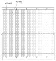
도 1은 정단면도.
도 2는 평면도.
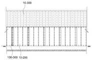
도 3은 측단면도.
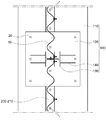
도 4는 지주부의 측단면도(도 1의 A부분의 확대도).
도 5는 지주부의 종단면도(도 4의 A-A 단면도).
도 6은 벽체부의 하부의 측단면도(도 4의 B부분의 확대도).
도 7은 벽체부의 종단면도(도 4의 B-B 단면도).
도 8은 도 7의 C부분의 확대도.
도 9는 벽체부의 상부의 측단면도.
도 10은 벽체부의 분해사시도.
도 11은 천정부의 단면도.1 is a perspective view of a corrugated steel plate reinforcing structure according to an embodiment of the present invention.
1 is a front sectional view.
2 is a plan view.
3 is a side sectional view.
4 is a side cross-sectional view of the holding portion (an enlarged view of a portion A in Fig. 1).
5 is a longitudinal sectional view of the support portion (AA sectional view in Fig. 4).
6 is a side sectional view of the lower portion of the wall portion (an enlarged view of a portion B in Fig. 4).
7 is a longitudinal sectional view of the wall portion (sectional view taken along line BB in Fig. 4).
8 is an enlarged view of a portion C in Fig.
9 is a side sectional view of an upper portion of the wall portion;
10 is an exploded perspective view of the wall portion;
11 is a sectional view of a ceiling portion.
이하, 첨부도면을 참조하여 본 발명의 실시예에 관하여 상세히 설명한다.Hereinafter, embodiments of the present invention will be described in detail with reference to the accompanying drawings.
도 1 이하에 도시된 바와 같이, 본 발명은 기본적으로 내부의 도로를 통해 운행하는 차량을 주위의 폭발사고로부터 보호하기 위한 방폭터널에 관한 것이다.DETAILED DESCRIPTION OF THE PREFERRED EMBODIMENTS As shown in FIG. 1 and below, the present invention basically relates to an explosion-proof tunnel for protecting a vehicle traveling on an inner road from an explosion in the surroundings.
이는 다수가 상호 간격을 두고 상하방향을 따라 이열(2열)로 설치된 지주부(100); 종단면이 파형을 이루도록, 다수의 파형강판(10)의 조립에 의해 벽체 구조로 형성됨과 아울러, 지주부(100) 사이에 설치된 벽체부(200); 횡단면이 파형을 이루도록, 다수의 파형강판(10)의 조립에 의해 아치형 구조로 형성됨과 아울러, 이열의 벽체부(200)의 상부를 덮도록 설치된 천정부(300);를 포함하여 구성된다.(100) in which a plurality of rows are arranged in a row (two rows) along the vertical direction at mutually spaced intervals; A
파형강판을 이용한 건설 구조물은 콘크리트 구조물에 비해, 자중이 작고 시공성이 우수하며 공기, 비용을 절감할 수 있다는 장점이 있으므로, 그 적용에 관한 연구가 활발히 진행되고 있다.As compared with a concrete structure, a construction structure using a corrugated steel sheet has advantages of being small in weight, excellent in workability, and capable of reducing air and cost, and therefore research on its application has been actively conducted.
다만 이러한 파형강판은 그 강도를 발휘함에 있어서 방향성이 중요하므로, 그 방향을 어떻게 배치할 것인가가 주된 이슈가 된다.However, since such corrugated steel sheet is important for its strength in exerting its strength, how to orient the corrugated steel sheet is a major issue.
본 발명은 이러한 파형강판을 이용하여 방폭터널을 형성한 것으로서, 벽체부(200)는 종단면이 파형을 이루도록 벽체 구조로 설치하고, 천정부(300)는 횡단면(길이방향 단면)이 파형을 이루도록 아치형 구조로 형성한 것이다.The
따라서 벽체부의 파형강판은 천정부의 하중 및 기타 자중에 대하여 효율적으로 저항할 수 있고, 위와 같이 설치되는 경우 약한 방향인 길이 방향에 대하여는 지주부(100)가 견고하게 지지하므로, 폭발에 의한 외력이 발생하더라도 파형강판과 지주부의 조합구조에 의해 효율적으로 저항할 수 있다는 효과가 있다.Therefore, the corrugated steel plate of the wall portion can efficiently resist the load of the ceiling portion and other self weight, and when the above-described installation is performed, the
지주부(100)는 구체적으로, 길이방향을 따라 지반에 콘크리트 구조로 설치된 기초부(110); 앵커(20)에 의해 기초부(110) 상부에 설치된 베이스 플레이트(120); 베이스 플레이트(120)의 상부에 설치된 H 파일(130); H 파일(130)의 하부와 베이스 플레이트(120)에 결합한 보강 플레이트(140);를 포함하여 구성된다(도 4,5).Specifically, the
이는 파형강판(10)의 약한 방향인 길이 방향을 지지하는 구조이므로 위와 같이 견고한 지지구조를 취한다.Since this structure supports the longitudinal direction of the
벽체부(200)는, 길이방향을 따라 지반에 콘크리트 구조로 설치된 기초부(110); 트임부가 상측을 향하는 "ㄷ"자형 단면 구조로 형성되고, 앵커(20)에 의해 기초부(110) 상부에 설치된 베이스 채널(210); 베이스 채널(210)에 하단이 삽입됨과 아울러, 볼트결합하도록 설치된 상기 파형강판(10);을 포함하여 구성된다(도 5 내지 7).The
이는 기초부(110)에 고정된 베이스 채널(210)에 대하여 파형강판(10)을 삽입하고 볼트결합하는 구조이므로, 시공성 및 구조적 안정성이 모두 우수하다.This is because the
H 파일(130)의 웹의 측면에 결합하는 결합판(221); 결합판(221)에서 외측으로 연장된 연장판(222);을 구비한 "ㄱ"자형 단면구조의 접합 앵글(220)을 H 파일(130)에 설치하고, 파형강판(10)의 돌출부(11)가 연장판(222)의 내면에 볼트결합하는 구조를 취하므로, H 파일(130)과 파형강판(10)의 견고한 결합을 쉽게 이룰 수 있다는 장점이 있다(도 8).A
벽체부(200)는, 파형강판(10)의 상부를 덮도록, H 파일(130)과 인접하여 설치되는 또 다른 H 파일(130)의 상부를 덮도록 설치되는 덮개부재(230); 천정부(300)의 파형강판(10)의 하단이 결합하도록, 트임부가 상측을 향하는 "ㄷ"자형 단면 구조로 형성되고, 덮개부재(230)의 상부에 설치된 벽체 채널(240);을 포함하여 구성된다(도 9,10).The
덮개부재(230)는 그 하부의 파형강판(10)을 보호함과 아울러, 양측의 H 파일(130)에 지지되어 천정부(300) 및 벽체 채널(240)의 하중을 하부로 전달하는 역할을 한다.The
구체적으로, 덮개부재(230)는, 벽체부(200)의 파형강판(10)을 덮도록 형성된 덮개판(231); H 파일(130)의 내외 플랜지(131)와 각각 볼트결합하도록, 덮개판(231)의 양단에서 하측으로 연장형성된 내외 연장판(232);을 포함하는 구조를 취하므로, H 파일(130)과의 결합시공이 용이하면서도 견고한 지지가 가능하다는 효과가 있다.Specifically, the
벽체 채널(240)의 트임부가 연직방향 상부를 향하는 구조를 취하는 경우, 이에 설치되는 천정부(300)의 단부가 연직방향으로 인입되어야 하므로, 천정부(300)의 상측이 상부로 많이 돌출되어야 한다는 문제가 있다.When the top portion of the
본 발명은 벽체 채널(240)이 내측을 향하여 경사지도록, 벽체 채널(240)과 덮개부재(230) 사이에 경사부재(250)를 설치하므로, 벽체 채널(240)에 설치되는 천정부(300)의 단부가 경사지게 인입할 수 있어 위 문제를 해소할 수 있다.Since the inclined member 250 is installed between the
위 경사부재(250)는 삼각형 단면 구조의 다수의 조각부재(251)를 포함하는 구조 등에 의해 구현될 수 있다.The upper inclined member 250 may be realized by a structure including a plurality of engraved members 251 having a triangular cross-sectional structure.
천정부(300)는, 중앙부(310); 중앙부(310)에 비해 곡률반경이 작도록, 양단에 형성된 양단부(320);를 포함하는 구조를 취하므로, 자재의 소요량을 최소화하면서 구조적 안정성을 극대화할 수 있다는 효과가 있다(도 11).The
이상은 본 발명에 의해 구현될 수 있는 바람직한 실시예의 일부에 관하여 설명한 것에 불과하므로, 주지된 바와 같이 본 발명의 범위는 위의 실시예에 한정되어 해석되어서는 안 될 것이며, 위에서 설명된 본 발명의 기술적 사상과 그 근본을 함께 하는 기술적 사상은 모두 본 발명의 범위에 포함된다고 할 것이다.It will be apparent to those skilled in the art that various modifications and variations can be made in the present invention without departing from the spirit or scope of the invention as defined in the appended claims. It is to be understood that both the technical idea and the technical spirit of the invention are included in the scope of the present invention.
10 : 파형강판
20 : 앵커
100 : 지주부
110 : 기초부
120 : 베이스 플레이트
130 : H 파일
140 : 보강 플레이트
200 : 벽체부
210 : 베이스 채널
220 : 접합 앵글
221 : 결합판
222 : 연장판
230 : 덮개부재
231 : 덮개판
232 : 내외 연장판
240 : 벽체 채널
250 : 경사부재
251 : 조각부재
300 : 천정부
310 : 중앙부
320 : 양단부10: corrugated steel plate 20: anchor
100: support part 110: base part
120: base plate 130: H file
140: reinforcing plate 200: wall part
210: base channel 220: joint angle
221: engaging plate 222: extended plate
230: lid member 231: lid plate
232: inner and outer extension plate 240: wall channel
250: slant member 251: piece member
300: Ceiling 310: Center
320: Both ends
Claims (9)
다수가 상호 간격을 두고 상하방향을 따라 이열로 설치된 지주부(100);
종단면이 파형을 이루도록, 다수의 파형강판(10)의 조립에 의해 벽체 구조로 형성됨과 아울러, 상기 지주부(100) 사이에 설치된 벽체부(200);
횡단면이 파형을 이루도록, 다수의 파형강판(10)의 조립에 의해 아치형 구조로 형성됨과 아울러, 상기 이열의 벽체부(200)의 상부를 덮도록 설치된 천정부(300);를
포함하는 것을 특징으로 하는 파형강판을 이용한 방폭터널.An explosion-proof tunnel for protecting a vehicle traveling on an internal road from an explosion in the vicinity,
A plurality of circumferentially spaced apart circumferentially spaced apart circumferential portions (100);
A wall part 200 formed as a wall structure by assembling a plurality of corrugated steel plates 10 so as to form a waveform in a longitudinal section, and a wall part 200 provided between the support parts 100;
A ceiling portion 300 formed to have an arcuate structure by assembling a plurality of corrugated steel plates 10 so as to form a waveform in a transverse section and to cover the upper portion of the wall portion 200 of the heat;
Wherein the reinforcing plate is formed of a steel plate.
상기 지주부(100)는,
길이방향을 따라 지반에 콘크리트 구조로 설치된 기초부(110);
앵커(20)에 의해 상기 기초부(110) 상부에 설치된 베이스 플레이트(120);
상기 베이스 플레이트(120)의 상부에 설치된 H 파일(130);
상기 H 파일(130)의 하부와 상기 베이스 플레이트(120)에 결합한 보강 플레이트(140);를
포함하는 것을 특징으로 하는 파형강판을 이용한 방폭터널.The method according to claim 1,
The support portion (100)
A foundation 110 installed in a concrete structure on the ground along the longitudinal direction;
A base plate (120) installed on the base (110) by an anchor (20);
An H file (130) installed on the base plate (120);
A reinforcing plate 140 coupled to a lower portion of the H file 130 and the base plate 120;
Wherein the reinforcing plate is formed of a steel plate.
상기 벽체부(200)는,
길이방향을 따라 지반에 콘크리트 구조로 설치된 기초부(110);
트임부가 상측을 향하는 "ㄷ"자형 단면 구조로 형성되고, 앵커(20)에 의해 상기 기초부(110) 상부에 설치된 베이스 채널(210);
상기 베이스 채널(210)에 하단이 삽입됨과 아울러, 볼트결합하도록 설치된 상기 파형강판(10);을
포함하는 것을 특징으로 하는 파형강판을 이용한 방폭터널.The method according to claim 1,
The wall portion 200 is formed of a metal,
A foundation 110 installed in a concrete structure on the ground along the longitudinal direction;
A base channel 210 formed on the upper portion of the base portion 110 by an anchor 20 and formed in a " C "
The corrugated steel plate 10 having the lower end inserted into the base channel 210 and bolted thereto;
Wherein the reinforcing plate is formed of a steel plate.
상기 벽체부(200)는,
상기 H 파일(130)의 웹의 측면에 결합하는 결합판(221);
상기 결합판(221)에서 외측으로 연장된 연장판(222);을 구비한 "ㄱ"자형 단면구조의 접합 앵글(220)을 더 포함하고,
상기 파형강판(10)의 돌출부(11)는 상기 연장판(222)의 내면에 볼트결합하는 것을 특징으로 하는 파형강판을 이용한 방폭터널.The method of claim 3,
The wall portion 200 is formed of a metal,
A coupling plate 221 coupled to a side surface of the web of the H file 130;
Further comprising a joining angle (220) of an "a" -shaped cross-sectional structure having an extension plate (222) extending outwardly from the coupling plate (221)
Wherein the projecting portion (11) of the corrugated steel plate (10) is bolted to the inner surface of the extending plate (222).
상기 벽체부(200)는,
상기 파형강판(10)의 상부를 덮도록, 상기 H 파일(130)과 인접하여 설치되는 또 다른 상기 H 파일(130)의 상부를 덮도록 설치되는 덮개부재(230);
상기 천정부(300)의 파형강판(10)의 하단이 결합하도록, 트임부가 상측을 향하는 "ㄷ"자형 단면 구조로 형성되고, 상기 덮개부재(230)의 상부에 설치된 벽체 채널(240);을
포함하는 것을 특징으로 하는 파형강판을 이용한 방폭터널.The method of claim 3,
The wall portion 200 is formed of a metal,
A lid member 230 installed to cover an upper portion of another H file 130 installed adjacent to the H file 130 so as to cover the upper portion of the corrugated steel plate 10;
A wall channel 240 formed on the upper part of the lid member 230 and having a "C" -shaped cross-sectional structure in which the ceiling portion faces upward so that the lower end of the corrugated steel plate 10 of the ceiling portion 300 is engaged;
Wherein the reinforcing plate is formed of a steel plate.
상기 덮개부재(230)는,
상기 벽체부(200)의 파형강판(10)을 덮도록 형성된 덮개판(231);
상기 H 파일(130)의 내외 플랜지(131)와 각각 볼트결합하도록, 상기 덮개판(231)의 양단에서 하측으로 연장형성된 내외 연장판(232);을
포함하는 것을 특징으로 하는 파형강판을 이용한 방폭터널.6. The method of claim 5,
The cover member (230)
A cover plate 231 formed to cover the corrugated steel plate 10 of the wall unit 200;
An inner and outer extension plate 232 extending downward from both ends of the cover plate 231 so as to be bolted to the inner and outer flanges 131 of the H file 130,
Wherein the reinforcing plate is formed of a steel plate.
상기 벽체부(200)는,
상기 벽체 채널(240)이 내측을 향하여 경사지도록, 상기 벽체 채널(240)과 상기 덮개부재(230) 사이에 설치된 경사부재(250);를
포함하는 것을 특징으로 하는 파형강판을 이용한 방폭터널.6. The method of claim 5,
The wall portion 200 is formed of a metal,
An inclined member 250 installed between the wall channel 240 and the lid member 230 such that the wall channel 240 is inclined inward;
Wherein the reinforcing plate is formed of a steel plate.
상기 경사부재(250)는 삼각형 단면 구조의 다수의 조각부재(251);를
포함하는 것을 특징으로 하는 파형강판을 이용한 방폭터널.8. The method of claim 7,
The inclined member 250 includes a plurality of engraving members 251 having a triangular cross-sectional structure
Wherein the reinforcing plate is formed of a steel plate.
상기 천정부(300)는,
중앙부(310);
상기 중앙부(310)에 비해 곡률반경이 작도록, 양단에 형성된 양단부(320);를
포함하는 것을 특징으로 하는 파형강판을 이용한 방폭터널.The method according to claim 1,
The ceiling portion (300)
A central portion 310;
Both ends 320 formed at both ends so that the radius of curvature is smaller than that of the center part 310
Wherein the reinforcing plate is formed of a steel plate.
Priority Applications (1)
| Application Number | Priority Date | Filing Date | Title |
|---|---|---|---|
| KR1020160008730A KR101861807B1 (en) | 2016-01-25 | 2016-01-25 | Explosion-proof tunnel using corrugated steel plate |
Applications Claiming Priority (1)
| Application Number | Priority Date | Filing Date | Title |
|---|---|---|---|
| KR1020160008730A KR101861807B1 (en) | 2016-01-25 | 2016-01-25 | Explosion-proof tunnel using corrugated steel plate |
Publications (2)
| Publication Number | Publication Date |
|---|---|
| KR20170088621A true KR20170088621A (en) | 2017-08-02 |
| KR101861807B1 KR101861807B1 (en) | 2018-05-28 |
Family
ID=59651928
Family Applications (1)
| Application Number | Title | Priority Date | Filing Date |
|---|---|---|---|
| KR1020160008730A KR101861807B1 (en) | 2016-01-25 | 2016-01-25 | Explosion-proof tunnel using corrugated steel plate |
Country Status (1)
| Country | Link |
|---|---|
| KR (1) | KR101861807B1 (en) |
Cited By (4)
| Publication number | Priority date | Publication date | Assignee | Title |
|---|---|---|---|---|
| JP2019108761A (en) * | 2017-12-20 | 2019-07-04 | Jfe建材株式会社 | Arch-shaped structure |
| CN110230416A (en) * | 2019-07-17 | 2019-09-13 | 黑龙江大千环保科技有限公司 | It is a kind of to have explosion-proof, shellproof storeroom structure |
| KR102274910B1 (en) * | 2021-03-08 | 2021-07-12 | 대한강관 주식회사 | Corrugated steel plate structure reinforcement structure combined with corrugated steel pipe filling concrete |
| CN114215599A (en) * | 2022-02-22 | 2022-03-22 | 中国矿业大学(北京) | Outburst prevention, dust fall and extraction integrated device for underground tunneling working face |
-
2016
- 2016-01-25 KR KR1020160008730A patent/KR101861807B1/en active IP Right Grant
Cited By (4)
| Publication number | Priority date | Publication date | Assignee | Title |
|---|---|---|---|---|
| JP2019108761A (en) * | 2017-12-20 | 2019-07-04 | Jfe建材株式会社 | Arch-shaped structure |
| CN110230416A (en) * | 2019-07-17 | 2019-09-13 | 黑龙江大千环保科技有限公司 | It is a kind of to have explosion-proof, shellproof storeroom structure |
| KR102274910B1 (en) * | 2021-03-08 | 2021-07-12 | 대한강관 주식회사 | Corrugated steel plate structure reinforcement structure combined with corrugated steel pipe filling concrete |
| CN114215599A (en) * | 2022-02-22 | 2022-03-22 | 中国矿业大学(北京) | Outburst prevention, dust fall and extraction integrated device for underground tunneling working face |
Also Published As
| Publication number | Publication date |
|---|---|
| KR101861807B1 (en) | 2018-05-28 |
Similar Documents
| Publication | Publication Date | Title |
|---|---|---|
| KR101861807B1 (en) | Explosion-proof tunnel using corrugated steel plate | |
| KR101969127B1 (en) | Corrugated metal plate and overhead structure incorporating same | |
| US20140123842A1 (en) | Blast shield | |
| US20160145819A1 (en) | Roadway barrier | |
| KR101414578B1 (en) | Underground tunnel having space for escaping emergency and constructing method thereof | |
| KR101736575B1 (en) | Assembled Reinforced Cap for Head of Pile | |
| JPWO2015108103A1 (en) | Metal deck of road bridge | |
| KR102057202B1 (en) | Device for connecting road barrier block | |
| CN211142809U (en) | Prefabricated assembled light-duty crashproof guardrail that excels in of bridge | |
| US11708679B2 (en) | CLT structure | |
| JP2014211076A (en) | Side gutter | |
| CN102852384A (en) | Fence upright | |
| JP5783278B2 (en) | Attaching structure of exterior panel to road side of rigid protective fence | |
| KR101355843B1 (en) | Guard fence reinforcing structure and method of installing thereof | |
| KR20090105123A (en) | Structure for protecting impact | |
| CN104358190A (en) | Hidden type exchangeable shearing joint | |
| JP3166369U (en) | Snow protection shelter | |
| JP6832696B2 (en) | Widening structure of the tunnel | |
| JP5880591B2 (en) | Attaching structure of exterior plate to the outer surface of rigid protective fence | |
| JP7042607B2 (en) | Beam material for vehicle guard rails and vehicle guard fences | |
| JP6588721B2 (en) | Bulk storage tank | |
| JP2005248636A (en) | Shaft structure | |
| JP3882009B2 (en) | Reinforcing material and method of reinforcing structure | |
| JP7037782B2 (en) | Arched structure | |
| KR101091544B1 (en) | Guardrail |
Legal Events
| Date | Code | Title | Description |
|---|---|---|---|
| A201 | Request for examination | ||
| E902 | Notification of reason for refusal | ||
| E701 | Decision to grant or registration of patent right | ||
| GRNT | Written decision to grant | ||
| R401 | Registration of restoration |