KR20170084207A - Glass-Polymer Laminates and Processes for Forming the Same - Google Patents
Glass-Polymer Laminates and Processes for Forming the Same Download PDFInfo
- Publication number
- KR20170084207A KR20170084207A KR1020177015835A KR20177015835A KR20170084207A KR 20170084207 A KR20170084207 A KR 20170084207A KR 1020177015835 A KR1020177015835 A KR 1020177015835A KR 20177015835 A KR20177015835 A KR 20177015835A KR 20170084207 A KR20170084207 A KR 20170084207A
- Authority
- KR
- South Korea
- Prior art keywords
- glass
- polymer
- polymer laminate
- layer
- temperature
- Prior art date
Links
Images


Classifications
-
- B—PERFORMING OPERATIONS; TRANSPORTING
- B32—LAYERED PRODUCTS
- B32B—LAYERED PRODUCTS, i.e. PRODUCTS BUILT-UP OF STRATA OF FLAT OR NON-FLAT, e.g. CELLULAR OR HONEYCOMB, FORM
- B32B17/00—Layered products essentially comprising sheet glass, or glass, slag, or like fibres
- B32B17/06—Layered products essentially comprising sheet glass, or glass, slag, or like fibres comprising glass as the main or only constituent of a layer, next to another layer of a specific material
- B32B17/10—Layered products essentially comprising sheet glass, or glass, slag, or like fibres comprising glass as the main or only constituent of a layer, next to another layer of a specific material of synthetic resin
-
- B32B17/064—
-
- B—PERFORMING OPERATIONS; TRANSPORTING
- B32—LAYERED PRODUCTS
- B32B—LAYERED PRODUCTS, i.e. PRODUCTS BUILT-UP OF STRATA OF FLAT OR NON-FLAT, e.g. CELLULAR OR HONEYCOMB, FORM
- B32B17/00—Layered products essentially comprising sheet glass, or glass, slag, or like fibres
- B32B17/06—Layered products essentially comprising sheet glass, or glass, slag, or like fibres comprising glass as the main or only constituent of a layer, next to another layer of a specific material
- B32B17/10—Layered products essentially comprising sheet glass, or glass, slag, or like fibres comprising glass as the main or only constituent of a layer, next to another layer of a specific material of synthetic resin
- B32B17/10005—Layered products essentially comprising sheet glass, or glass, slag, or like fibres comprising glass as the main or only constituent of a layer, next to another layer of a specific material of synthetic resin laminated safety glass or glazing
- B32B17/10009—Layered products essentially comprising sheet glass, or glass, slag, or like fibres comprising glass as the main or only constituent of a layer, next to another layer of a specific material of synthetic resin laminated safety glass or glazing characterized by the number, the constitution or treatment of glass sheets
- B32B17/10018—Layered products essentially comprising sheet glass, or glass, slag, or like fibres comprising glass as the main or only constituent of a layer, next to another layer of a specific material of synthetic resin laminated safety glass or glazing characterized by the number, the constitution or treatment of glass sheets comprising only one glass sheet
-
- B—PERFORMING OPERATIONS; TRANSPORTING
- B32—LAYERED PRODUCTS
- B32B—LAYERED PRODUCTS, i.e. PRODUCTS BUILT-UP OF STRATA OF FLAT OR NON-FLAT, e.g. CELLULAR OR HONEYCOMB, FORM
- B32B17/00—Layered products essentially comprising sheet glass, or glass, slag, or like fibres
- B32B17/06—Layered products essentially comprising sheet glass, or glass, slag, or like fibres comprising glass as the main or only constituent of a layer, next to another layer of a specific material
- B32B17/10—Layered products essentially comprising sheet glass, or glass, slag, or like fibres comprising glass as the main or only constituent of a layer, next to another layer of a specific material of synthetic resin
- B32B17/10005—Layered products essentially comprising sheet glass, or glass, slag, or like fibres comprising glass as the main or only constituent of a layer, next to another layer of a specific material of synthetic resin laminated safety glass or glazing
- B32B17/1055—Layered products essentially comprising sheet glass, or glass, slag, or like fibres comprising glass as the main or only constituent of a layer, next to another layer of a specific material of synthetic resin laminated safety glass or glazing characterized by the resin layer, i.e. interlayer
- B32B17/10743—Layered products essentially comprising sheet glass, or glass, slag, or like fibres comprising glass as the main or only constituent of a layer, next to another layer of a specific material of synthetic resin laminated safety glass or glazing characterized by the resin layer, i.e. interlayer containing acrylate (co)polymers or salts thereof
-
- B—PERFORMING OPERATIONS; TRANSPORTING
- B32—LAYERED PRODUCTS
- B32B—LAYERED PRODUCTS, i.e. PRODUCTS BUILT-UP OF STRATA OF FLAT OR NON-FLAT, e.g. CELLULAR OR HONEYCOMB, FORM
- B32B17/00—Layered products essentially comprising sheet glass, or glass, slag, or like fibres
- B32B17/06—Layered products essentially comprising sheet glass, or glass, slag, or like fibres comprising glass as the main or only constituent of a layer, next to another layer of a specific material
- B32B17/10—Layered products essentially comprising sheet glass, or glass, slag, or like fibres comprising glass as the main or only constituent of a layer, next to another layer of a specific material of synthetic resin
- B32B17/10005—Layered products essentially comprising sheet glass, or glass, slag, or like fibres comprising glass as the main or only constituent of a layer, next to another layer of a specific material of synthetic resin laminated safety glass or glazing
- B32B17/10807—Making laminated safety glass or glazing; Apparatus therefor
- B32B17/1099—After-treatment of the layered product, e.g. cooling
-
- B—PERFORMING OPERATIONS; TRANSPORTING
- B32—LAYERED PRODUCTS
- B32B—LAYERED PRODUCTS, i.e. PRODUCTS BUILT-UP OF STRATA OF FLAT OR NON-FLAT, e.g. CELLULAR OR HONEYCOMB, FORM
- B32B27/00—Layered products comprising a layer of synthetic resin
- B32B27/30—Layered products comprising a layer of synthetic resin comprising vinyl (co)polymers; comprising acrylic (co)polymers
- B32B27/308—Layered products comprising a layer of synthetic resin comprising vinyl (co)polymers; comprising acrylic (co)polymers comprising acrylic (co)polymers
-
- B—PERFORMING OPERATIONS; TRANSPORTING
- B32—LAYERED PRODUCTS
- B32B—LAYERED PRODUCTS, i.e. PRODUCTS BUILT-UP OF STRATA OF FLAT OR NON-FLAT, e.g. CELLULAR OR HONEYCOMB, FORM
- B32B37/00—Methods or apparatus for laminating, e.g. by curing or by ultrasonic bonding
-
- B—PERFORMING OPERATIONS; TRANSPORTING
- B32—LAYERED PRODUCTS
- B32B—LAYERED PRODUCTS, i.e. PRODUCTS BUILT-UP OF STRATA OF FLAT OR NON-FLAT, e.g. CELLULAR OR HONEYCOMB, FORM
- B32B37/00—Methods or apparatus for laminating, e.g. by curing or by ultrasonic bonding
- B32B37/12—Methods or apparatus for laminating, e.g. by curing or by ultrasonic bonding characterised by using adhesives
-
- B—PERFORMING OPERATIONS; TRANSPORTING
- B32—LAYERED PRODUCTS
- B32B—LAYERED PRODUCTS, i.e. PRODUCTS BUILT-UP OF STRATA OF FLAT OR NON-FLAT, e.g. CELLULAR OR HONEYCOMB, FORM
- B32B7/00—Layered products characterised by the relation between layers; Layered products characterised by the relative orientation of features between layers, or by the relative values of a measurable parameter between layers, i.e. products comprising layers having different physical, chemical or physicochemical properties; Layered products characterised by the interconnection of layers
- B32B7/04—Interconnection of layers
- B32B7/12—Interconnection of layers using interposed adhesives or interposed materials with bonding properties
-
- B—PERFORMING OPERATIONS; TRANSPORTING
- B32—LAYERED PRODUCTS
- B32B—LAYERED PRODUCTS, i.e. PRODUCTS BUILT-UP OF STRATA OF FLAT OR NON-FLAT, e.g. CELLULAR OR HONEYCOMB, FORM
- B32B2307/00—Properties of the layers or laminate
- B32B2307/50—Properties of the layers or laminate having particular mechanical properties
- B32B2307/58—Cuttability
- B32B2307/581—Resistant to cut
-
- B—PERFORMING OPERATIONS; TRANSPORTING
- B32—LAYERED PRODUCTS
- B32B—LAYERED PRODUCTS, i.e. PRODUCTS BUILT-UP OF STRATA OF FLAT OR NON-FLAT, e.g. CELLULAR OR HONEYCOMB, FORM
- B32B2309/00—Parameters for the laminating or treatment process; Apparatus details
- B32B2309/08—Dimensions, e.g. volume
- B32B2309/10—Dimensions, e.g. volume linear, e.g. length, distance, width
- B32B2309/105—Thickness
-
- B—PERFORMING OPERATIONS; TRANSPORTING
- B32—LAYERED PRODUCTS
- B32B—LAYERED PRODUCTS, i.e. PRODUCTS BUILT-UP OF STRATA OF FLAT OR NON-FLAT, e.g. CELLULAR OR HONEYCOMB, FORM
- B32B2333/00—Polymers of unsaturated acids or derivatives thereof
- B32B2333/04—Polymers of esters
- B32B2333/12—Polymers of methacrylic acid esters, e.g. PMMA, i.e. polymethylmethacrylate
Abstract
유리-중합체 적층은 최대 약 300㎛의 두께를 갖는 유리 층 및 상기 유리 층에 적층된 중합체 층을 포함한다. 약 16℃ 내지 약 32℃의 온도 범위 내에 모든 온도에서, 상기 유리 층은 압축 응력을 가지며, 상기 유리-중합체 적층은 최대 약 150N의 보우 평탄화 힘을 갖는다. 방법은 유리 층을 중합체 층에 적층 온도에서 접착제로 적층시켜 유리-중합체 적층을 형성하는 적층 단계를 포함한다. 상기 유리 층은 최대 약 300㎛의 두께를 갖는다. 상기 적층 온도는 약 16℃ 내지 약 32℃의 온도 범위 내에 모든 온도에서, 유리 층이 압축 응력을 갖도록 충분히 높다. 상기 적층 온도는, 상기 온도 범위 내의 모든 온도에서, 유리-중합체 적층이 최대 약 150N의 보우 평탄화 힘을 갖도록 충분히 낮다. The glass-polymer laminate comprises a glass layer having a thickness of up to about 300 [mu] m and a polymer layer laminated to the glass layer. At all temperatures within a temperature range of about 16 ° C to about 32 ° C, the glass layer has a compressive stress and the free-polymer laminate has a bow planarizing force of up to about 150N. The method includes a laminating step of laminating the glass layer to the polymer layer with an adhesive at the laminating temperature to form a glass-polymer laminate. The glass layer has a thickness of up to about 300 mu m. The lamination temperature is sufficiently high so that the glass layer has a compressive stress at all temperatures within a temperature range of about 16 캜 to about 32 캜. The lamination temperature is low enough at all temperatures within the temperature range that the free-polymer laminate has a bow flattening force of up to about 150N.
Description
본 출원은 2014년 11월 17일자로 출원된 미국 가 특허출원 제62/080,764호의 우선권을 주장하며, 이의 전체적인 내용은 여기에 참조로서 혼입된다.This application claims priority of U.S. Provisional Patent Application No. 62 / 080,764, filed November 17, 2014, the entire contents of which are incorporated herein by reference.
본 개시는 유리-중합체 적층 (glass-polymer laminate)에 관한 것으로서, 좀 더 상세하게는, 이러한 유리-중합체 적층이 파괴 없이 절단되고 설치 가능하도록, 결정된 응력 및 보우 특성 (bowing characteristics)을 갖는 유리-중합체 적층 및 이러한 유리-중합체 적층을 형성하기 위한 공정 및 장치에 관한 것이다. This disclosure relates to glass-polymer laminates and more particularly to glass-polymer laminates having determined stress and bowing characteristics such that such glass-polymer laminates can be cut and installed without breaking, Polymer laminate and processes and apparatus for forming such a glass-polymer laminate.
적층 유리 구조물 (Laminated glass structures)은 다양한 가전제품, 자동차 부품, 건축 구조물, 또는 전자 장치의 제조에 구성요소로 사용될 수 있다. 예를 들어, 적층 유리 구조물은 냉장고, 백스플래시 (backsplashes), 장식용 그레이징 (decorative glazing) 또는 텔레비전과 같은 다양한 최종 제품에 대한 커버유리로서 혼입될 수 있다. 그러나, 유리 층을 파괴하지 않고 현장에서 (예를 들어, 설치 장소에서) 적층 유리 구조물을 절단 및 설치하는 것이 어려울 수 있다. 예를 들어, 넓은 온도 범위에 대해 적층 유리 구조물의 절단 및 설치를 가능하게 하는 것이 바람직할 것이다. Laminated glass structures can be used as components in the manufacture of various consumer products, automotive components, building structures, or electronic devices. For example, laminated glass structures can be incorporated as cover glasses for a variety of end products such as refrigerators, backsplashes, decorative glazing, or televisions. However, it may be difficult to cut and install the laminated glass structure in situ (e.g., at the installation site) without destroying the glass layer. For example, it would be desirable to be able to cut and install a laminated glass structure over a wide temperature range.
유리-중합체 적층 및 이를 형성하는 방법은 여기에 개시된다. Glass-polymer laminates and methods for forming them are disclosed herein.
본 발명은 최대 약 300㎛의 두께를 포함하는 유리 층 및 상기 유리 층에 적층된 중합체 층을 포함하는 유리-중합체 적층은 여기에 개시된다. 약 16℃ 내지 약 32℃의 온도 범위 내에 모든 온도에서, 상기 유리 층은 압축 응력을 포함하고, 및 상기 유리-중합체 적층은 최대 약 150N의 보우 평탄화 힘 (bow flattening force)을 포함한다. The present invention discloses here a glass-polymer laminate comprising a glass layer comprising a thickness of up to about 300 탆 and a polymer layer laminated to said glass layer. At all temperatures within a temperature range of about 16 ° C to about 32 ° C, the glass layer comprises compressive stresses and the glass-polymer laminate comprises a bow flattening force of up to about 150N.
적층 온도 (lamination temperature)에서 접착제로 중합체 층에 유리 층을 적층시켜 유리-중합체 적층을 형성하는, 적층 단계를 포함하는 방법은 여기에 개시된다. 상기 유리 층은 최대 약 300㎛의 두께를 포함한다. 상기 적층 온도는, 약 16℃ 내지 약 32℃의 온도 범위 내에 모든 온도에서, 유리 층이 압축 응력을 포함하도록 충분히 높다. 상기 적층 온도는, 약 16℃ 내지 약 32℃의 온도 범위 내에 모든 온도에서, 유리-중합체 적층이 최대 약 150N의 보우 평탄화 힘을 포함하도록 충분히 낮다. A method involving a lamination step of laminating a glass layer to a polymer layer with an adhesive at a lamination temperature to form a glass-polymer laminate is disclosed herein. The glass layer comprises a thickness of up to about 300 [mu] m. The lamination temperature is sufficiently high such that, at all temperatures within a temperature range of from about 16 DEG C to about 32 DEG C, the glass layer comprises compressive stress. The lamination temperature is sufficiently low such that at all temperatures within the temperature range of about 16 [deg.] C to about 32 [deg.] C, the free-polymer laminate comprises a bow planarizing force of up to about 150N.
부가적인 특색들 및 장점들은 하기 상세한 설명에서 서술될 것이고, 부분적으로는 그 상세한 설명으로부터 당업자에게 쉽게 명백할 것이며, 또는 하기 상세한 설명, 청구 범위뿐만 아니라 첨부된 도면을 포함하는, 여기에 기재된 구체 예들을 실행하여 인지될 것이다. Additional features and advantages will be set forth in the description which follows, and in part will be readily apparent to those skilled in the art from the detailed description, or may be learned by those skilled in the art from the detailed description herein, including the appended drawings, Will be recognized.
전술한 배경 기술 및 하기 상세한 설명 모두는 단지 대표적인 것이며, 청구 범위의 본질 및 특성을 이해하기 위한 개요 또는 틀거리를 제공하도록 의도된 것으로 이해될 것이다. 첨부 도면은 또 다른 이해를 제공하기 위해 포함되며, 본 명세서에 통합되어 본 명세서의 일부를 구성한다. 도면은 하나 이상의 구체 예(들)를 예시하고, 상세한 설명과 함께 다양한 구체 예의 원리 및 작동을 설명하는 역할을 한다. It is to be understood that both the foregoing background and the following detailed description are exemplary only and are intended to provide an overview or framework for understanding the nature and character of the claims. The accompanying drawings are included to provide further understanding and are incorporated in and constitute a part of this specification. The drawings illustrate one or more embodiments (s) and serve to explain the principles and operation of the various embodiments, along with the detailed description.
도 1은 유리-중합체 적층의 하나의 대표적인 구체 예의 단면도이다.
도 2는 다수의 온도에서 유리-중합체 적층의 짧은 중심선을 따른 위치의 함수에 따라 단축의 방향으로 대표적인 유리-중합체 적층의 유리 층에서 응력의 그래프적 예시이다.
도 3은 다수의 온도에서 유리-중합체 적층의 짧은 중심선을 따른 위치의 함수에 따라 장축의 방향으로 대표적인 유리-중합체 적층의 유리 층에서의 응력의 그래프적 예시이다.
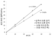
도 4는 적층 온도로부터의 ΔT의 함수에 따라 대표적인 유리-중합체 적층에서 보우 (bow)의 그래픽적 예시이다.
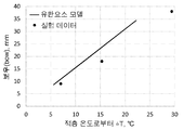
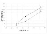
도 5는 적층 온도로부터의 ΔT의 함수에 따라 대표적인 유리-중합체 적층의 보우 평탄화 힘의 그래프적 예시이다.
도 6은 대표적인 유리-중합체 적층의 온도 한계 및 온도 한계와 응력 및 보우 한계 사이에 관계의 그래프적 예시이다.
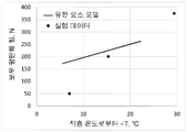
도 7은 적층 온도로부터의 ΔT의 함수에 따라 각각의 장축 및 단축에 따른 대표적인 유리-중합체 적층의 유리 층에서 최대 압축 응력의 그래프적 예시이다.
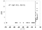
도 8은 적층 온도로부터 ΔT의 함수에 따라 대표적인 유리-중합체 적층을 절단하는 동안 부품당 균열의 수의 그래프적 예시이다.
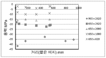
도 9는 다른 크기의 유리-중합체 적층에서 유리-중합체 적층의 짧은 중심선에 따른 위치의 함수에 따라 단축의 방향으로 대표적인 유리-중합체 적층의 유리 층에서 응력의 그래프적 예시이다.
도 10은 다른 크기의 유리-중합체 적층에서 유리-중합체 적층의 짧은 중심선을 따른 위치의 함수에 따라 장축의 방향에서 대표적인 유리-중합체 적층의 유리 층에서의 응력의 그래프적 예시이다.
도 11은 유리-중합체 적층의 2개의 다른 크기에 대한 적층 온도의 함수에 따라 22℃에서 측정된 대표적인 유리-중합체 적층의 보우를 비교하는 그래프적 예시이다.
도 12는 유리-중합체 적층의 2개의 다른 크기에 대한 적층 온도로부터의 ΔT의 함수에 따라 유리-중합체 적층의 모델링된 보우를 비교한 그래프적 예시이다.
도 13은 유리-중합체 적층의 2개의 다른 크기에 대한 적층 온도의 함수에 따라 22℃에서 측정된 모델링된 보우 평탄화 힘을 비교한 그래프적 예시이다.
도 14는 유리-중합체 적층의 2개의 다른 크기에 대한 적층 온도로부터 ΔT의 함수에 따라 유리-중합체 적층의 모델링된 보우 평탄화 힘을 비교한 그래프적 예시이다.
도 15는 2개의 다른 두께의 중합체 층에 대한 적층 온도로부터 ΔT의 함수에 따라 유리-중합체 적층의 모델링된 보우를 비교한 그래프적 예시이다.
도 16은 2개의 다른 두께의 중합체 층에 대한 적층 온도로부터의 ΔT의 함수에 따라 유리-중합체 적층의 유리 층의 모델링된 최대 응력을 비교한 그래프적 예시이다.
도 17은 대표적인 절단 공정 및 최종 출구 균열 (resulting exit cracking)에 의해 형성된 마감 절단을 나타내는 사진의 선화 복제 (line drawing drawing reproduction)이다.
도 18은 유리-중합체 적층에 형성된 대표적인 노치 (notch)를 나타내는 사진의 선화 복제이다. Figure 1 is a cross-sectional view of one exemplary embodiment of a glass-polymer laminate.
Figure 2 is a graphical example of stress in a glass layer of a representative glass-polymer laminate in the direction of the minor axis according to a function of position along the short centerline of the glass-polymer laminate at multiple temperatures.
Figure 3 is a graphical illustration of the stresses in the glass layer of a typical glass-polymer laminate in the direction of the major axis according to a function of position along the short centerline of the glass-polymer laminate at multiple temperatures.
Figure 4 is a graphical illustration of a bow in a representative glass-polymer laminate according to a function of [Delta] T from the lamination temperature.
Figure 5 is a graphical illustration of a bow planarizing force of a representative glass-polymer laminate according to a function of [Delta] T from the lamination temperature.
Figure 6 is a graphical example of the relationship between temperature and temperature limits and stress and bow limits of a representative glass-polymer laminate.
Figure 7 is a graphical illustration of the maximum compressive stresses in a glass layer of a representative free-polymer laminate according to their respective long and short axes as a function of [Delta] T from the lamination temperature.
Figure 8 is a graphical illustration of the number of cracks per component during cutting a representative free-polymer laminate according to a function of [Delta] T from the lamination temperature.
Figure 9 is a graphical example of stress in a glass layer of a representative glass-polymer laminate in the direction of the minor axis as a function of position along the short centerline of the glass-polymer laminate in the glass-polymer laminate of another size.
10 is a graphical illustration of the stresses in the glass layer of a representative glass-polymer laminate in the direction of the major axis according to a function of position along the short centerline of the glass-polymer laminate in different sizes of glass-polymer laminate.
Figure 11 is a graphical example comparing the bow of a representative glass-polymer laminate measured at 22 占 폚 according to a function of the lamination temperature for two different sizes of glass-polymer laminate.
Figure 12 is a graphical example comparing the modeled bow of a free-polymer stack according to a function of DELTA T from the lamination temperature for two different sizes of the free-polymer laminate.
13 is a graphical example comparing the modeled bow planarization forces measured at 22 DEG C as a function of lamination temperature for two different sizes of glass-polymer laminates.
14 is a graphical example comparing the modeled bow planarization forces of a free-polymer stack according to a function of DELTA T from the lamination temperature for two different sizes of the free-polymer laminate.
FIG. 15 is a graphical example comparing the modeled bow of a free-polymer laminate according to a function of? T from the lamination temperature for two different thickness polymer layers.
Figure 16 is a graphical example comparing the modeled maximum stresses of the glass layer of a free-polymer laminate according to a function of [Delta] T from the lamination temperature for two different thickness polymer layers.
Figure 17 is a line drawing drawing reproduction of a photograph showing a finish cut formed by a typical cutting process and resulting exit cracking.
Figure 18 is a phylogenetic reproduction of a photograph representing a representative notch formed in a glass-polymer laminate.
이하 첨부된 도면에 예시된 대표적인 구체 예들에 대해 상세하게 언급될 것이다. 가능한 한, 동일한 참조 번호는 동일하거나 유사한 부분을 나타내기 위해 도면 전체에 걸쳐 사용될 것이다. 도면의 구성요소는 반드시 스케일이 아니며, 대신에 대표적인 구체 예의 원리를 예시할 때 강조된다. Reference will now be made in detail to representative embodiments illustrated in the accompanying drawings. Wherever possible, the same reference numbers will be used throughout the drawings to refer to the same or like parts. The components of the figures are not necessarily to scale, emphasis instead being placed upon illustrating the principles of the exemplary embodiments.
다양한 구체 예에서, 유리-중합체 적층은 최대 약 300㎛의 두께를 갖는 유리 층 및 상기 유리 층에 적층된 중합체 층을 포함한다. 상기 유리 층, 중합체 층 및/또는 적층 공정의 특성은, 약 16℃ 내지 약 32℃의 온도 범위 내에 모든 온도에서, 상기 유리 층이 압축 응력을 포함하고 및 상기 유리-중합체 적층은 최대 약 150N의 보우 평탄화 힘을 포함하도록 조절된다. In various embodiments, the free-polymer laminate comprises a glass layer having a thickness of up to about 300 [mu] m and a polymer layer laminated to the glass layer. The properties of the glass layer, polymer layer and / or laminating process are such that at all temperatures within a temperature range of about 16 ° C to about 32 ° C, the glass layer comprises compressive stresses and the glass- And is adjusted to include a bow planarizing force.
여기서 사용된 바와 같은, 그리고 별도의 언급이 없는 한, 용어 "열팽창계수"는 유리 물질 또는 층에 대해 20℃ 내지 300℃ 및 중합체 물질 또는 층에 대해 0℃ 내지 40℃의 온도 범위에서 걸쳐 물질 또는 층의 평균 열팽창계수 (CTE)를 나타낸다. The term "coefficient of thermal expansion ", as used herein and unless otherwise indicated, refers to the temperature of a material or layer over a temperature range of from 20 캜 to 300 캜 and from 0 캜 to 40 캜 over the polymeric material or layer, (CTE) of the layer.
여기에 사용된 바와 같은, 용어 "보우 (bow)"는 굽은 유리-중합체 적층에 의해 나타나는 곡률의 양을 나타낸다. 상기 보우는 굽은 유리-중합체 적층을 평면에 놓고, 평면과 상기 평면으로부터 유리-중합체 적층의 최대 변위 사이에 최대 거리를 측정하여 결정된다. As used herein, the term "bow" refers to the amount of curvature exhibited by a curved glass-polymer laminate. The bow is determined by placing the curved glass-polymer laminate in a plane and measuring the maximum distance between the plane and the maximum displacement of the glass-polymer laminate from the plane.
여기에 사용된 바와 같은, 용어 "보우 평탄화 힘"은, 굽은 유리-중합체 적층을 실질적으로 평면 형상으로 압력을 가하기에 충분한 최소 힘을 의미한다. 상기 보우 평탄화 힘은 유리-중합체 적층이 실질적으로 평면 형상일 때까지 굽은 유리-중합체 적층에 증가하는 힘을 가하여 (예를 들어, 유리-중합체 적층 상에 중량을 가하여) 결정된다. 힘은 보우를 결정할 때 평면에서 가장 먼 유리-중합체 적층의 에지에 적용된다. 예를 들어, 유리-중합체 적층이 장축을 중심으로 굽어진 경우, 상기 힘은 유리-중합체 적층의 긴 에지에 적용된다. 선택적으로, 유리-중합체 적층이 단축을 중심으로 굽어진다면, 상기 힘은 유리-중합체 적층의 짧은 에지에 적용된다. 상기 힘은 유리-중합체 적층의 마주보는 에지에 대칭적으로 적용된다. 예를 들어, 대칭적으로 힘을 가하기 위해 유리-중합체 적층의 마주보는 긴 에지 또는 마주보는 짧은 에지에 동일한 양의 중량을 놓을 수 있다. As used herein, the term "bow planarizing force" means a minimum force sufficient to apply pressure to a curved glass-polymer laminate in a substantially planar configuration. The bow planarizing force is determined by applying an increasing force (e. G., By weighting on the glass-polymer laminate) to the curved glass-polymer laminate until the glass-polymer laminate is substantially planar. The force is applied to the edge of the glass-polymer laminate farthest from the plane when determining the bow. For example, when the glass-polymer laminate is curved about a long axis, the force is applied to the long edge of the glass-polymer laminate. Optionally, if the glass-polymer laminate is curved around a minor axis, the force is applied to the short edge of the glass-polymer laminate. The force is applied symmetrically to the opposing edges of the glass-polymer laminate. For example, the same amount of weight can be placed on opposing long or facing short edges of the glass-polymer laminate to apply a force symmetrically.
여기에 기재된 유리-중합체 적층은 건축 적용으로 사용될 수 있다. 예를 들어, 유리-중합체 적층은 장식용 패널 (예를 들어, 백스플래시 또는 벽 패널) 및/또는 기능성 패널 (예를 들어, 화이트 보드 또는 프로젝션 스크린)로 사용될 수 있다. 이러한 적용에서, 유리-중합체 적층을 생산 장소에서 생산한 다음 유리-중합체 적층을 절단하여 설치 위치의 현지 (즉, 현장)에서 크기를 정하는 것이 유리할 수 있다. 또한, 광범위한 온도에서 유리-중합체 적층을 절단하고 설치할 수 있는 것이 유리할 수 있다. 예를 들어, 설치 위치의 현장 온도는, 년 중 다른 시간대 (예를 들어, 여름 대 겨울) 또는 다른 지리적 위치에 따라 상당히 다를 수 있으며, 유리-중합체 적층 또는 이의 일부 (예를 들어, 유리 층)를 파괴하지 않고 다양한 지리적 위치에서 및 년 중 다른 시간대에서 유리-중합체 적층을 절단 및 설치할 수 있는 것이 유리할 수 있다. The glass-polymer laminates described herein can be used in architectural applications. For example, the glass-polymer laminate can be used as a decorative panel (e.g., a backs flash or a wall panel) and / or a functional panel (e.g., a whiteboard or projection screen). In such an application, it may be advantageous to produce the glass-polymer laminate at the production site and then cut the glass-polymer laminate to size at the site (i.e., site) of the installation location. It may also be advantageous to be able to cut and install the glass-polymer laminate at a wide range of temperatures. For example, the site temperature of the installation location can vary considerably depending on different time zones (e.g., summer versus winter) or other geographic locations of the year, and may be a glass-polymer laminate or a portion thereof (e.g., It may be advantageous to be able to cut and install glass-polymer laminates at various geographic locations and at different times of the year.
일반적으로, 유리 층의 CTE 및 중합체 층의 CTE는 실질적으로 다르다. 예를 들어, 유리 층의 CTE는 여기에 기재된 바와 같이 중합체 층의 CTE보다 실질적으로 작다. 유리 층과 중합체 층 사이에 CTE 불일치는, 유리-중합체 적층의 절단 및 설치 및/또는 유리-중합체 적층의 작동 수명에 대한 온도 범위를 제한할 수 있는 두 가지 영향을 결과할 수 있다. Generally, the CTE of the glass layer and the CTE of the polymer layer are substantially different. For example, the CTE of the glass layer is substantially less than the CTE of the polymer layer as described herein. The CTE mismatch between the glass layer and the polymer layer may result in two effects that may limit the temperature range for cutting and installation of the glass-polymer laminate and / or operating life of the glass-polymer laminate.
CTE 불일치의 제1 영향은 유리 층의 응력이다. 적층 온도에서, 유리 층 및 중합체 층의 응력은 0이다. 유리-중합체 적층의 온도가 적층 온도 이상으로 증가함에 따라, 유리 층에서의 인장 응력은 유리가 파단될 때까지 증가한다. 이는 유리-중합체 적층이 절단될 수 있는 최대 온도 및 마감 후 유리-중합체 적층의 수명 동안의 최대 온도를 제한한다. The first effect of the CTE mismatch is the stress in the glass layer. At the lamination temperature, the stresses of the glass layer and the polymer layer are zero. As the temperature of the glass-polymer laminate increases above the lamination temperature, the tensile stress in the glass layer increases until the glass breaks. This limits the maximum temperature at which the glass-polymer laminate can be cut and the maximum temperature during the lifetime of the glass-polymer laminate after finishing.
CTE 불일치의 제2 영향은 유리-중합체 적층의 보우이다. 보우는, 유리가 압축된 경우, 적층 온도 이하의 온도에서 가장 분명하다. 유리-중합체 적층의 온도가 적층 온도 이하로 감소함에 따라, 증가하는 힘의 양은 유리-중합체 적층을 평평하게 하기 위해 요구된다. 다시 말하면, 유리-중합체 적층의 온도가 적층 온도 이하로 감소함에 따라, 유리-중합체 적층의 보우 평탄화 힘은 증가한다. 영구 접착제가 (예를 들어, 설치 동안) 경화되면서 평면에 대해 그 자리에 유리-중합체 적층을 유지하는데 감압 접착제 (pressure sensitive adhesive)가 사용되는 경우, 유리-중합체 적층의 보잉 (bowing)은 평면으로부터 임시 접착제를 당길 수 있고, 및 영구 접착제의 적절한 부착을 방지한다. 더 낮은 온도는 감압 접착제의 접착력을 제한할 수 있으며, 이는 설치 공정을 더욱 제한하며 및 더 낮은 보잉 유도 평탄화 힘에 유리한다. The second effect of the CTE mismatch is the bow of the glass-polymer laminate. The bow is most evident at temperatures below the lamination temperature when the glass is compressed. As the temperature of the glass-polymer laminate decreases below the lamination temperature, the amount of increasing force is required to flatten the glass-polymer laminate. In other words, as the temperature of the free-polymer laminate decreases below the lamination temperature, the bow planarizing force of the free-polymer laminate increases. If a pressure sensitive adhesive is used to hold the glass-polymer laminate in place against the plane while the permanent adhesive is cured (e.g., during installation), the bowing of the glass-polymer laminate will be from plane Pull the temporary adhesive, and prevent proper attachment of the permanent adhesive. Lower temperatures can limit the adhesion of the pressure sensitive adhesive, which further limits the installation process and benefits the lower Boeing induced planarization forces.
더 높은 절단 온도 (cutting temperatures)에서 유리 층에서 허용할 수 없는 높은 인장 응력을 피하기 위해 적층 온도를 증가시키는 것이 유리할 수 있다. 더 낮은 설치 온도 (installation temperatures)에서 허용할 수 없는 높은 보우 평탄화 힘을 피하기 위해 적층 온도를 감소시키는 것이 또한 유리할 수 있다. 따라서, 고온 절단 한계 및 저온 설치 한계는 반대 방향으로 적층 온도를 조정하도록 하는 경쟁 목표이다.It may be advantageous to increase the lamination temperature to avoid unacceptably high tensile stresses in the glass layer at higher cutting temperatures. It may also be advantageous to reduce the lamination temperature to avoid unacceptably high bow flattening forces at lower installation temperatures. Thus, the high temperature cutting limit and the low temperature setting limit are competing targets to adjust the lamination temperature in the opposite direction.
유리 층 및 중합체 층의 특성 및 적층 공정은 결정된 온도 범위에 걸쳐 유리-중합체 적층의 절단 및 설치를 가능하도록 여기에 기재된 바와 같이 조절될 수 있다. 예를 들어, 몇몇 구체 예에서, 유리-중합체 적층은, 여기에 기재된 바와 같이 적어도 35℃의 고온 절단 및 설치 한계, 최대 16℃의 저온 설치 한계, 및/또는 최대 0℃의 저온 수명 한계를 갖는다. The properties of the glass and polymer layers and the lamination process can be adjusted as described herein to enable the cutting and installation of the glass-polymer laminate over the determined temperature range. For example, in some embodiments, the free-polymer laminate has a high temperature cutting and installation limit of at least 35 占 폚 as described herein, a low temperature installation limit of up to 16 占 폚, and / or a low temperature lifetime limit of up to 0 占.
도 1은 유리-중합체 적층 (100)의 하나의 대표적인 구체 예의 단면도이다. 유리-중합체 적층 (100)은 유리 층 (110), 중합체 층 (120), 및 유리 층 (110)과 중합체 층 (120) 사이에 배치된 접착제 층 (130)을 포함한다. 따라서, 중합체 층 (120)은 접착제 층 (130)으로 유리 층 (110)에 적층된다. 몇몇 구체 예에서, 유리-중합체 적층 (100)은, 도 1에 나타낸 바와 같은, 적층 시트를 포함한다. 적층 시트는 길이, 폭, 및 두께를 갖는다. 길이는 가장 긴 치수이고, 두께가 가장 작은 치수이다. 각각의 길이 및 폭은 두께보다 실질적으로 더 크다 (예를 들어, 적어도 10배 더 크다). 적층 시트는 실질적으로 평면 (즉, 평평한) 또는 비-평면 (즉, 만곡)일 수 있다. 다른 구체 예에서, 유리-중합체 적층은 3-차원 (3D) 형상을 포함한다. 예를 들어, 3D 형상은 성형 장치에서 적층 시트를 성형하여 형성될 수 있다. Figure 1 is a cross-sectional view of one exemplary embodiment of a glass-
몇몇 구체 예에서, 유리 층 (110)은 유연한 유리 층을 포함한다. 따라서, 유리 층 (110)은 최대 약 300㎛, 최대 약 200㎛, 최대 약 150㎛, 또는 최대 약 100㎛의 두께를 포함한다. 부가적으로 또는 선택적으로, 유리 층 (110)은 적어도 약 50㎛의 두께를 포함한다. 예를 들어, 유리 층 (110)은 약 150㎛ 내지 약 250㎛의 두께를 포함한다. 유리 층 (110)은 유리 물질, 세라믹 물질, 유리-세라믹 물질, 또는 이들의 조합을 포함한다. In some embodiments, the
유리 층 (110)은 적절한 형성 공정을 사용하여 형성될 수 있다. 예를 들어, 유리 층 (110)은 퓨전 공정 (fusion process)과 같은 다운인발 공정을 사용하여 형성될 수 있다. 퓨전 공정을 사용하여 유리 층 (110)을 형성하는 것은 다른 방법에 의해 생산된 유리 시트와 비교하여 유리 층이 우수한 평탄도 및 평활도를 갖는 표면을 갖는 것이 가능할 수 있다. 퓨전 공정은 미국 특허 제3,338,696호 및 제3,682,609호에 기재되어 있다. 다른 적절한 유리 형성 공정은 플로우트 공정, 업인발 공정, 또는 슬롯 인발 공정을 포함할 수 있다. 몇몇 구체 예에서, 유리 층 ((110)은 항균 특성을 포함한다. 예를 들어, 유리 층 (110)은, 미국 공개 특허출원 제2012/0034435호에 기재된 바와 같이, 0 ㎍/㎠ 초과 내지 0.047 ㎍/㎠의 범위에서 유리 층 표면에 은 이온농도를 포함한다. 부가적으로 또는 선택적으로, 유리 층 (110)은, 미국 공개 특허출원 제2011/0081542호에 기재된 바와 같은 원하는 항균 특성을 얻기 위해, 은을 포함하는 유약 (glaze)으로 코팅되거나, 또는 은 이온으로 도핑된다. 부가적으로 또는 선택적으로, 유리 층 (110)은 원하는 항-균 효과를 달성하기 위해 50% SiO2, 25% CaO, 및 25% Na2O의 몰 조성물을 포함한다. The
몇몇 구체 예에서, 중합체 층 (120)은 적어도 약 2mm, 적어도 약 3mm, 적어도 약 4mm, 또는 적어도 약 5mm의 두께를 포함한다. 부가적으로 또는 선택적으로, 중합체 층 (120)은 최대 약 10mm, 최대 약 9mm, 최대 약 8mm, 최대 약 7mm 또는 최대 약 6mm의 두께를 포함한다. 예를 들어, 중합체 층 (120)은 약 2.9 mm 내지 약 6.1 mm, 약 3.9 mm 내지 약 6.1 mm 또는 약 5.1 mm 내지 약 6.1 mm의 두께를 포함한다. 중합체 층 (120)은, 예를 들어, 폴리에틸렌 테레프탈레이트 (PET), 폴리에틸렌 나프탈레이트 (PEN), 에틸렌 테트라플루오로에틸렌 (ETFE), 열중합체 (thermopolymer) 폴리올레핀 (폴리에틸렌, 폴리프로필렌, 블럭 공중합체 폴리프로필렌 (BCPP), 또는 고무의 TPO™-중합체/충진제 블랜드), 폴리에스테르, 폴리카보네이트, 폴리비닐부테레이트, 폴리염화비닐 (PVC), 폴리에틸렌 또는 치환된 폴리티에닐렌, 폴리하이드록시부티레이트, 폴리하이드록시비닐부티레이트, 폴리비닐아세틸렌, 투명한 열가소성 수지, 투명한 폴리부타디엔, 폴리시아노알릴레이트, 셀룰로오스-계 중합체, 폴리아크릴레이트, 폴리메타아크릴레이트, 폴리비닐알코올 (PVA), 폴리설파이드, 폴리비닐 부티랄 (PVB), 폴리(메틸 메타아크릴레이트) (PMMA), 폴리실록산, 또는 이의 조합과 같은 중합체 물질을 포함한다. 중합체 층 (120)은 투명, 반투명 또는 불투명일 수 있다. 몇몇 구체 예에서, 중합체 층 (120)은, 유리 층 (110)을 통해 보이는 색상, 장식 패턴, 또는 디자인을 포함한다. 중합체 층 (120)은 중합체 층을 형성하기 위해 함께 적층된 단일 층 또는 다중 층을 포함할 수 있다. 예를 들어, 중합체 층 (120)은 장식 필름의 장식 색상 또는 패턴이 유리 층 (110)을 통해 보이도록 중합체 기판 층 및 상기 중합체 기판 층의 표면상에 배치된 장식 필름을 포함할 수 있다. In some embodiments, the
몇몇 구체 예에서, 접착제 층 (130)은 적어도 약 10 ㎛, 적어도 약 20 ㎛, 적어도 약 30 ㎛, 또는 적어도 약 40 ㎛의 두께를 포함한다. 부가적으로 또는 선택적으로, 접착제 층 (130)은 최대 약 100㎛, 최대 약 90㎛, 최대 약 70㎛, 또는 최대 약 60㎛의 두께를 포함한다. 예를 들어, 접착제 층 (130)은 약 25㎛ 내지 약 75㎛의 두께를 포함한다. 접착제 층 (130)은 비-접착성 중간층, 접착제의 시트 또는 필름, 액체 접착제, 분말 접착제, 감압 접착제, 자외선 (UV) 경화성 접착제, 열경화성 접착제, 다른 적절한 접착제 또는 이들의 조합을 포함한다. 예를 들어, 접착제 층 (130)은, 예를 들어, (UV에 의해 경화되는) Norland 68, (실온에서 가압에 의해 결합되는) 3M OCA 8211 또는 8212, 3M 4905, OptiClear® 접착제, 실리콘, 아크릴레이트, 광학적으로 투명한 접착제, 앤캡슐런트 (encaptulant) 물질, 폴리우레탄, 또는 나무 아교 (wood glue)와 같은 저온 접착제를 포함한다. 부가적으로 또는 선택적으로, 접착제 층 (130)은, 예를 들어, DuPont SentryGlas, DuPont PV 5411, Japan World Corporation material FAS, 또는 폴리비닐 부티랄 수지와 같은 고온 접착제를 포함한다. 몇몇 구체 예에서, 접착제 층 (130)은, 예를 들어, 착색제, 장식, 열 또는 UV 저항제 (resistance agent) 또는 AR 여과제 (filtration agent)와 같은 하나 이상의 기능성 성분을 포함한다. 접착제 층 (130)은 경화시 광학적으로 투명 또는 불투명할 수 있다. 몇몇 구체 예에서, 접착제 층 (130)은 유리 층 (110)을 통해 보이는 색상, 장식 패턴, 또는 디자인을 갖거나 또는 갖지 않는 시트 또는 필름을 포함한다. In some embodiments, the
중합체 층 (120)은 유리-중합체 적층 (100)을 형성하기 위해 적절한 적층 공정을 사용하여 유리 층 (110)에 적층될 수 있다. 예를 들어, 중합체 층 (120)은 시트-대-시트 (S2S) 적층 공정을 사용하여 유리 층 (110)에 적층될 수 있고, 여기서 압력 및/또는 열은 접착제 층 (130)을 사용하여 중합체 층에 유리 층을 결합하는데 사용된다. 선택적으로, 중합체 층 (120)은 롤-대-시트 (R2S) 또는 롤-대-롤 (R2R) 적층 공정을 사용하여 유리 층 (110)에 적층될 수 있고, 여기서 압력은 공급 롤 (supply roll) 또는 복수의 개별 시트로부터의 연속적 리본으로 중합체 층에 공급 롤로부터 유리 층의 연속적 리본을 결합하는데 사용된다. 적층 공정은 여기에 기재된 바와 같이 유리-중합체 적층에 원하는 특성을 부여하도록 조절될 수 있다. 적층 후에, 유리-중합체 적층 (110)은, 여기에 기재된 바와 같이, 또한 절단 및/또는 설치될 수 있다.The
몇몇 구체 예에서, 유리 층 (110) 및/또는 중합체 층 (120)의 특성 (예를 들어, CTE 또는 탄성 계수); 유리 층, 중합체 층, 및/또는 유리-중합체 적층 (100)의 치수; 및/또는 적층 조건 (예를 들어, 적층 온도)은, 약 16℃ 내지 약 32℃의 온도 범위에 걸쳐 유리-중합체 적층의 절단 및 설치를 가능하도록 조절된다. 예를 들어, 약 16℃ 내지 약 32℃의 온도 범위 내에 모든 온도에서, 유리 층 (110)은 압축 응력을 포함하고, 및 유리-중합체 적층 (100)은 최대 약 150N의 보우 평탄화 힘을 포함한다. 부가적으로, 또는 선택적으로, 유리-중합체 적층 (100)은 약 32.2℃의 절단 온도에서 휴대용 전동 공구로 절단을 견딜 수 있다. In some embodiments, properties (e.g., CTE or modulus of elasticity) of the
몇몇 구체 예에서, 유리 층 (110)은 적어도 약 0.5x10⁻⁶℃-1, 적어도 약 1x10⁻⁶℃-1, 적어도 약 1.5x10⁻⁶℃-1, 적어도 약 2x10⁻⁶℃-1, 또는 적어도 약 2.5x10⁻⁶℃-1의 CTE를 포함한다. 부가적으로 또는 선택적으로, 유리 층 (110)은 최대 약 9x10⁻⁶℃-1, 최대 약 8x10⁻⁶℃-1, 최대 약 7x10⁻⁶℃-1, 최대 약 6x10⁻⁶℃-1, 최대 약 5x10⁻⁶℃-1, 또는 최대 약 4x10⁻⁶℃-1의 CTE를 포함한다. 예를 들어, 유리 층 (110)은 약 2.7x10⁻⁶℃-1 내지 약 3.7x10⁻⁶℃-1의 CTE를 포함한다.In some embodiments, the
몇몇 구체 예에서, 중합체 층 (120)은 적어도 약 20x10-6℃-1, 적어도 약 30x10-6℃-1, 적어도 약 40x10-6℃-1, 적어도 약 50x10-6℃-1, 적어도 약 60x10-6℃-1, 또는 적어도 약 70x10-6℃-1의 CTE를 포함한다. 부가적으로 또는 선택적으로, 중합체 층 (120)은 최대 약 130x10-6℃-1, 최대 약 120x10-6℃-1, 최대 약 110x10-6℃-1, 최대 약 100x10-6℃-1, 최대 약 90x10-6℃-1, 또는 최대 약 80x10-6℃-1의 CTE를 포함한다. 예를 들어, 중합체 층 (120)은 약 74.5x10⁻⁶℃-1 내지 약 75.5x10⁻⁶℃-1의 CTE를 포함한다.In some embodiments, the
몇몇 구체 예에서, 유리 층 (110)과 중합체 층 (120) 사이에 CTE 또는 CTE 불일치의 차이는, 적어도 약 10x10-6℃-1, 적어도 약 20x10-6℃-1, 적어도 약 30x10-6℃-1, 적어도 약 40x10-6℃-1, 적어도 약 50x10-6℃-1, 적어도 약 60x10-6℃-1, 또는 적어도 약 70x10-6℃-1이다. In some embodiments, the difference in CTE or CTE mismatch between the
몇몇 구체 예에서, 유리 층 (110) 및 중합체 층 (120)은 도 1을 참조하여 여기서 기재된 바와 같은 두께를 포함한다. 이러한 구체 예에서, 유리-중합체 적층 (100)은 적어도 약 100mm, 적어도 약 200mm, 적어도 약 300mm, 적어도 약 400mm, 적어도 약 500mm 또는 적어도 약 600mm의 폭을 포함한다. 부가적으로 또는 선택적으로, 유리-중합체 적층은 최대 약 1300 mm, 최대 약 1200 mm, 최대 약 1100 mm, 최대 약 1000 mm, 최대 약 900 mm, 또는 최대 약 800 mm의 폭을 포함한다. 예를 들어, 유리-중합체 적층은 약 640mm 내지 약 740mm의 폭을 포함한다. 이러한 구체 예에서, 유리-중합체 적층 (100)은 적어도 약 2000mm, 적어도 약 2100mm, 적어도 약 2200mm, 적어도 약 2300mm, 적어도 약 2400mm 또는 적어도 약 2500mm의 길이를 포함한다. 부가적으로 또는 선택적으로, 유리-중합체 적층은 최대 약 3200 mm, 최대 약 3100 mm, 최대 약 3000 mm, 최대 약 2900 mm, 최대 약 2800 mm, 또는 최대 약 2700 mm의 길이를 포함한다. 예를 들어, 유리-중합체 적층은 약 2570 mm 내지 약 2670 mm의 길이를 포함한다. In some embodiments, the
몇몇 구체 예에서, 유리 층 (110)은 유리-중합체 적층 (100)을 형성하기 위해 적층 온도에서 접착제 층 (130)으로 중합체 층 (120)에 적층된다. 적층 온도는, 약 16℃ 내지 약 32℃의 온도 범위 내에 모든 온도에서, 유리 층 (110)이 압축 응력을 포함하도록 충분히 높다. 적층 온도는, 약 16℃ 내지 약 32℃의 온도 범위 내에 모든 온도에서, 유리-중합체 적층 (100)이 최대 약 150 N의 보우 평탄화 힘을 포함하도록 충분히 낮다. 몇몇 구체 예에서, 적층 온도는, 적어도 약 30℃ 또는 적어도 약 33℃이다. 부가적으로, 또는 선택적으로, 적층 온도는 최대 약 45℃, 최대 약 40℃, 또는 최대 약 37℃이다. 예를 들어, 적층 온도는 약 30℃ 내지 약 45℃, 약 30℃ 내지 약 40℃, 또는 약 33℃ 내지 약 37℃이다. In some embodiments, the
몇몇 구체 예에서, 유리-중합체 적층 (100)은 적층 온도보다 낮은 절단 온도에서 휴대용 전동 공구로 절단된다. 예를 들어, 휴대용 전동 공구는 라우터 (router) 또는 톱 (예를 들어, 테이블 톱)을 포함한다. 적층 온도 이하의 절단 온도에서 유리-중합체 적층 (100)을 절단하는 것은, 절단 동안 유리 층 (110)이 압축하에 있고 유리 층의 파괴를 피하는데 도움이 될 수 있다. 몇몇 구체 예에서, 유리-중합체 적층(100)을 절단하는 단계는, 유리-중합체 적층의 제1 에지에 노치 (notch)를 형성하는 단계 및 제1 에지의 반대편의 제2 에지로부터 노치를 향하여 유리 중합체 적층을 절단하는 단계를 포함한다. In some embodiments, the free-
몇몇 구체 예에서, 유리-중합체 적층 (100)은 적층 온도보다 낮은 또는 적층 온도보다 최대 약 5℃ 초과하는 설치 온도에서 실질적으로 평면에 결합된다. 예를 들어, 실질적으로 평면은 벽, 천장, 바닥, 조리대 또는 벤치탑 (benchtop), 테이블 탑 또는 다른 적절한 표면을 포함한다. 몇몇 구체 예에서, 설치 온도는 적어도 약 16℃이다. 예를 들어, 설치 온도는 약 16℃ 내지 약 40℃ 또는 약 16℃ 내지 약 35℃이다. 약 16℃ 내지 적층 온도의 설치 온도에서 유리-중합체 적층을 설치하는 것은, 보우 평탄화 힘이 설치 동안 충분히 낮고 (예를 들어, 최대 약 150 N), 유리 층 (110)이 설치 동안 유리 층의 파괴를 피하는 압축하에 있는 것을 보장하는데 도움을 줄 수 있다. 몇몇 구체 예에서, 유리-중합체 적층 (100)을 실질적으로 평면에 결합시키는 단계는, 유리-중합체 적층과 실질적으로 평면 사이에 제1 접착제 및 제2 접착제를 적용하는 단계 및 제2 접착제가 경화되는 동안 제1 접착제로 실질적으로 평면상의 위치에 유리-중합체 적층을 유지하는 단계를 포함한다. 예를 들어, 제1 접착제는 감압 접착제를 포함한다. 부가적으로 또는 선택적으로, 제2 접착제는 실리콘-계 접착제를 포함한다. 감압 접착제로 제 위치에 유리-중합체 적층 (100)을 유지하는 것은, 실리콘-계 접착제가 경화되는 것을 가능하게 하여 실질적으로 평면상의 제자리에 유리-중합체 적층을 고정시킬 수 있다. In some embodiments, the free-
실시 예Example
비교 예Comparative Example
도 1에 나타낸 일반적인 구조를 갖는 유리-중합체 적층은 S2S 적층 공정 및 약 22℃의 적층 온도를 사용하여 접착제 층으로 유리 층에 중합체 층을 적층시켜 형성된다. 유리 층은 3.2x10⁻⁶℃-1의 CTE 및 74 GPa의 탄성 계수를 갖는 알칼리토 보로알루미노실리케이트 유리로부터 형성된다. 중합체 층은 약 75x10-6℃-1의 CTE 및 3 GPa의 탄성 계수를 갖는 PMMA로 형성된다. 접착제 층은 중합체 층보다 낮은 탄성 계수를 갖는 광학적으로 투명한 감압 접착제로 형성된다. 유리 층은 200㎛의 두께를 갖는다. 중합체 층은 5.6 mm의 두께를 갖는다. 접착제 층은 50㎛의 두께를 갖는다. 유리-중합체 적층은 직사각형의 형상이며, 및 920 mm의 폭 및 2620 mm의 길이를 갖는다. A glass-polymer laminate having the general structure shown in Fig. 1 is formed by laminating a polymer layer on a glass layer with an adhesive layer using an S2S lamination process and a lamination temperature of about 22 < 0 > C. The glass layer is formed from an alkali toboro aluminosilicate glass having a CTE of 3.2 x 10 < -6 > C < -1 > and an elastic modulus of 74 GPa. The polymer layer is formed of PMMA having a CTE of about 75x10 < -6 > C < -1 > and an elastic modulus of 3 GPa. The adhesive layer is formed of an optically transparent pressure-sensitive adhesive having a lower modulus of elasticity than the polymer layer. The glass layer has a thickness of 200 mu m. The polymer layer has a thickness of 5.6 mm. The adhesive layer has a thickness of 50 mu m. The glass-polymer laminate is rectangular in shape, and has a width of 920 mm and a length of 2620 mm.
유리-중합체 적층은 휴대용 전동 공구로 절단되어, 이의 사전-적층 조건으로부터 유리 층의 강도에서 상당한 변화를 결과한다. 라우터 또는 테이블 톱으로의 절단은, 100mm x 50mm 4-점 굽힘 표본 (four-point bend specimen)을 사용하여 측정된 약 20MPa의 B10 유리 에지 강도를 결과한다. 크기 통계 (size statistics) 및 유리 피로 (fatigue)에 대하여 이 강도의 조정은, B10 유리 에지 강도를 약 5MPa로 감소시킨다. 절단 에지에 마감 단계의 부가는, B10 에지 강도를 약 70MPa로 개선시킨다. 크기 통계 및 유리 피로에 대하여 이 강도의 조정은, B10 유리 에지 강도를 약 12MPa로 감소시킨다. The glass-polymer laminate is cut into a portable power tool resulting in a significant change in the strength of the glass layer from its pre-lamination conditions. Cutting to a router or tabletop results in a B 10 glass edge strength of about 20 MPa, measured using a 100 mm x 50 mm four-point bend specimen. Adjustment of this intensity for size statistics and free fatigue reduces the B 10 glass edge strength to about 5 MPa. The addition of the finishing step to the cutting edge improves the B 10 edge strength to about 70 MPa. Adjustment of this strength against size statistics and free fatigue reduces the B 10 glass edge strength to about 12 MPa.
유리 층의 응력은 유리-중합체 적층의 짧은 중심선을 따라 다수의 지점에서 2개의 직교 방향으로 측정된다. 각 방향에서 최대 응력 값은 적층의 중심에 있는 것으로 밝혀졌다. 도 2는 다수의 온도에서 유리-중합체 적층의 짧은 중심선을 따른 위치의 함수에 따라 단축의 방향에서 유리 층의 응력의 그래프적 예시이다. 도 3은 다수의 온도에서 유리-중합체 적층의 짧은 중심선을 따른 위치의 함수에 따라 장축 방향에서 유리 층의 응력의 그래프적 예시이다. 도 2-3에서, 음의 값은 압축 응력을 나타내고, 및 양의 값은 인장 응력을 나타낸다. The stress in the glass layer is measured in two orthogonal directions at multiple points along the short centerline of the glass-polymer laminate. The maximum stress values in each direction were found to be at the center of the stack. Figure 2 is a graphical illustration of the stresses in the glass layer in the direction of the minor axis according to a function of position along the short centerline of the glass-polymer laminate at multiple temperatures. Figure 3 is a graphical example of the stresses in the glass layer in the major axis direction as a function of position along the short centerline of the glass-polymer laminate at multiple temperatures. In Fig. 2-3, negative values represent compressive stresses, and positive values represent tensile stresses.
도 2에 나타낸 바와 같이, 중심선을 따른 위치가 에지에 접근함에 따라, 그 에지에 수직인 방향의 응력은 0에 접근한다. 도 3에 나타낸 바와 같이, 에지에 평행한 방향에서 응력은, 중심선을 따른 위치가 그 에지에 접근함에 따라, 감소할 가능성이 더 적다. 도 2는 약 2.4MPa/℃의 온도에 대한 응력 민감도 (stress sensitivity)를 나타내고, 및 도 3은 약 3.3MPa/℃의 응력 민감도를 나타낸다. 실험값은 2 MPa/℃ 내지 4 MPa/℃의 범위이다. 분석 모델링 및 유한 요소 모델링 (finite element modeling)은, 약 3 MPa/℃의 민감도를 나타내는, 실험값과 잘 일치하며, 및 PMMA의 CTE 및 탄성 계수와 같은 입력 특성에 크게 의존한다. As shown in Fig. 2, as the position along the centerline approaches the edge, the stress in the direction perpendicular to that edge approaches zero. As shown in Fig. 3, the stress in the direction parallel to the edge is less likely to decrease as the position along the centerline approaches the edge. Figure 2 shows the stress sensitivity for a temperature of about 2.4 MPa / 占 폚, and Figure 3 shows a stress sensitivity of about 3.3 MPa / 占 폚. The experimental value is in the range of 2 MPa / 占 폚 to 4 MPa / 占 폚. Analytical modeling and finite element modeling are in good agreement with experimental data showing a sensitivity of about 3 MPa / ° C and are highly dependent on input properties such as CTE and modulus of elasticity of PMMA.
온도에 대한 이러한 응력 민감도의 잠재적인 문제점은, 적층 온도 이상으로 유리-중합체 적층의 온도에서 2℃ 증가가 유리 층 파괴에 충분한 응력을 발생시킬 수 있고, 및 적층 온도 이상으로 유리-중합체 적층의 온도에서 4℃ 증가가 이의 수명 동안 어느 지점에서 마감된 에지를 갖는 유리 층을 파괴하기에 충분한 응력을 발생시킬 수 있다는 점이다. A potential problem with this stress sensitivity to temperature is that a 2 [deg.] C increase in the temperature of the glass-polymer laminate above the lamination temperature can produce sufficient stress for the glass laminate failure and that the temperature of the glass- Lt; RTI ID = 0.0 > 4 C < / RTI > may generate enough stress to break the glass layer with the edges closed at some point during its lifetime.
유리-중합체 적층의 온도는 적층 온도 이하로 감소되어, PMMA가 유리보다 더 많이 수축되고 상기 적층의 보잉을 결과한다. 예상외로, 상기 보잉은 단축이 아니라 적층의 장축에 대해 일어난다. 상기 보잉은 유한 요소 모델을 사용하여 모델링된다. 이 모델은 보잉이 실험적으로 관찰된 것과 같은 방향으로 발생하도록 강제된다. 도 4는 적층 온도로부터 ΔT, 또는 적층 온도와 보우가 측정되는 유리-중합체 적층의 온도 사이에 차이의 함수에 따라 유리-중합체 적층에서 보우의 그래프적 예시이다. 선 (line)은, 3000MPa의 실험값과 대조적으로, PMMA의 탄성 계수에 대해 1300MPa의 값을 사용하여 보우를 예측하는 유한 요소 모델의 결과를 나타낸다. 탄성 계수가 높을수록 더 딱딱한 유리-중합체 적층, 및 도 4에 나타낸 데이터 점에 의해 나타낸 바와 같이 더 작은 양의 보잉을 결과한다. 이 모델은 약 1.6mm/℃의 ΔT에 대한 보우 민감도를 나타내고, 및 실험 데이터는 약 1.3mm/℃의 ΔT에 대한 보우 민감도를 나타낸다. The temperature of the glass-polymer laminate is reduced below the lamination temperature, so that the PMMA shrinks more than glass and results in a bowing of the laminate. Unexpectedly, the Boeing occurs not on the short axis but on the long axis of the laminate. The Boeing is modeled using a finite element model. This model is forced to occur in the same direction that Boeing experimentally observed. 4 is a graphical illustration of a bow in a glass-polymer laminate according to a function of the difference from the lamination temperature, [Delta] T, or the difference between the lamination temperature and the temperature of the free-polymer laminate from which the bow is measured. The line shows the result of a finite element model that predicts the bow using a value of 1300 MPa for the modulus of elasticity of the PMMA, as opposed to an experimental value of 3000 MPa. The higher the modulus of elasticity results, the stiffer glass-polymer lamination, and a smaller amount of bowing as shown by the data points shown in Fig. This model represents the bow sensitivity to DELTA T of about 1.6 mm / DEG C, and the experimental data show Bow Sensitivity to DELTA T of about 1.3 mm / DEG C.
도 5는 적층 온도로부터의 ΔT의 함수에 따라 유리-중합체 적층의 보우 평탄화 힘의 그래프적 예시이다. 실험 데이터는 유리-중합체 적층을 평탄하게 하기 위해 유리-중합체 적층상에 중량 (weights)을 놓아 결정된다. 그래프의 상부 우측 코너에 있는 데이터 점은 가능한 최대 힘이 적용될 때 보우가 완전히 제거되지 않았음을 나타낸다. 선은 보우 평탄화 힘을 예측하는 유한 요소 모델의 결과를 나타낸다. 이 모델은 약 5.4 N/℃의 ΔT에 대한 보우 평탄화 힘 민감도를 나타내며, 및 실험 데이터는 >14 N/℃의 ΔT에 대한 보우 평탄화 힘 민감도를 나타낸다. 보우 평탄화 힘이 150N 이상으로 증가함에 따라, 유리-중합체 적층을 접착테이프로 벽에 장착하는 것은 대단히 어렵게 된다. Figure 5 is a graphical illustration of the bow planarizing force of a free-polymer laminate according to a function of [Delta] T from the lamination temperature. The experimental data is determined by placing weights on the glass-polymer laminate to level the glass-polymer laminate. The data points at the upper right corner of the graph indicate that the bow has not been completely removed when the maximum possible force is applied. The line shows the result of a finite element model predicting the bow planarization force. This model represents the bow planarization force sensitivity for? T of about 5.4 N / 占 폚, and the experimental data represents the bow planarization force sensitivity for? T of > 14 N / 占 폚. As the bow planarization force increases to over 150 N, it becomes very difficult to mount the glass-polymer laminate to the wall with adhesive tape.
유리-중합체 적층은, 여기에 기재된 바와 같이, 적어도 35℃의 고온 절단 및 설치 한계, 최대 16℃의 저온 설치 한계, 및/또는 최대 0℃의 저온 수명 한계를 갖는 것이 유리할 수 있다. The glass-polymer laminate may advantageously have a high temperature cutting and installation limit of at least 35 占 폚, a low temperature installation limit of up to 16 占 폚, and / or a low temperature service life limit of 0 占 폚, as described herein.
22℃에서 적층된, 비교 예의 유리-중합체 적층은, 고온 절단 및 설치 한계에서 유리 층에 65 MPa의 인장 응력을 가지게 되어, 절단 동안 또는 절단 전에 유리 층이 파괴될 가능성이 있다. 비교 예의 유리-중합체 적층은 저온 설치 한계에서 250N 이상의 보우 평탄화 힘을 가질 것이어서, 유리-중합체 적층의 설치를 어렵게 할 가능성 있다. The glass-polymer laminate of the comparative example, laminated at 22 占 폚, has a tensile stress of 65 MPa in the glass layer at the high temperature cutting and installation limits, and there is a possibility that the glass layer is broken during cutting or before cutting. The glass-polymer laminates of the comparative examples will have a bow planarization force of at least 250 N at low temperature installation limits, which may make it difficult to install glass-polymer laminates.
실시 예 1Example 1
도 6은 유리-중합체 적층의 온도 한계 및 상기 온도 한계와 응력과 보우 한계 사이에 관계를 나타내는 그래프적 예시이다. 유리 층 및/또는 중합체 층의 특성 (예를 들어, CTE 또는 탄성 계수); 유리 층, 중합체 층, 및/또는 유리-중합체 적층의 치수; 및/또는 적층 조건 (예를 들어, 적층 온도)은, 보잉 및 응력 선의 기울기를 변화시키고 및 원하는 절단, 설치, 및/또는 수명 온도 창 (life temperature windows)을 달성하도록 조정될 수 있다.Figure 6 is a graphical example showing the temperature limit of a glass-polymer laminate and the relationship between the temperature limit and the stress and bow limits. (E.g., CTE or modulus of elasticity) of the glass layer and / or the polymer layer; The dimensions of the glass layer, the polymer layer, and / or the glass-polymer laminate; And / or lamination conditions (e. G., Lamination temperatures) can be adjusted to change the slope of the bowing and stress lines and achieve desired cutting, installation, and / or life temperature windows.
도 1에 나타낸 일반적인 구조를 갖는 유리-중합체 적층은, S2S 적층 공정 및 약 35℃의 적층 온도를 사용하여 접착제 층으로 유리 층에 중합체 층을 적층하여 형성된다. 유리 층은 3.2x10⁻⁶℃-1의 CTE 및 74 GPa의 탄성 계수를 갖는 알칼리토 보로알루미노실리케이트 유리로부터 형성된다. 중합체 층은 약 75x10-6℃-1의 CTE 및 3 GPa의 탄성 계수를 갖는 PMMA로 형성된다. 접착제 층은 중합체 층보다 낮은 탄성 계수를 갖는 광학적으로 투명한 감압 접착제로 형성된다. 유리 층은 200㎛의 두께를 갖는다. 중합체 층은 5.6 mm의 두께를 갖는다. 접착제 층은 50㎛의 두께를 갖는다. 유리-중합체 적층은 직사각형의 형상이며 및 690 mm의 폭 및 2620 mm의 길이를 갖는다. 따라서, 실시 예 1의 유리-중합체 적층은, 적층 온도가 22℃가 아닌 35℃이고, 폭이 920 mm가 아닌, 690 mm인 점에서, 비교 예의 유리-중합체 적층과 다르다. A glass-polymer laminate having the general structure shown in Fig. 1 is formed by laminating a polymer layer on a glass layer with an adhesive layer using an S2S lamination process and a lamination temperature of about 35 캜. The glass layer is formed from an alkali toboro aluminosilicate glass having a CTE of 3.2 x 10 < -6 > C < -1 > and an elastic modulus of 74 GPa. The polymer layer is formed of PMMA having a CTE of about 75x10 < -6 > C < -1 > and an elastic modulus of 3 GPa. The adhesive layer is formed of an optically transparent pressure-sensitive adhesive having a lower modulus of elasticity than the polymer layer. The glass layer has a thickness of 200 mu m. The polymer layer has a thickness of 5.6 mm. The adhesive layer has a thickness of 50 mu m. The glass-polymer laminate is rectangular in shape and has a width of 690 mm and a length of 2620 mm. Thus, the free-polymer laminate of Example 1 differs from the glass-polymer laminate of the comparative example in that the lamination temperature is 35 ° C instead of 22 ° C, and the width is 690 mm rather than 920 mm.
적층 온도는 유리 층에 적층하는 동안 중합체 층을 가열하도록 구성된 적층 장치를 사용하여 조절된다. 중합체 층 및 유리 층은, 중합체 층과 유리 층 사이의 접착제 층과 함께 교차 경로를 따라 적층 방향으로 중합체 층 및 유리 층을 제공하도록 진행된다. 중합체 층이 진행되는 운반 장치는, 중합체 층을 향하는 적외선 (IR) 히터 및 대류 히터를 포함하여 상기 중합체 층을 유리 층과의 적층 전에 적층 온도로 가열한다. The lamination temperature is controlled using a lamination apparatus configured to heat the polymer layer during lamination to the glass layer. The polymer layer and the glass layer proceed with the adhesive layer between the polymer layer and the glass layer to provide a polymer layer and a glass layer in the lamination direction along a crossing path. The conveyor apparatus in which the polymer layer proceeds includes an infrared (IR) heater and a convective heater directed toward the polymer layer to heat the polymer layer to the lamination temperature prior to lamination with the glass layer.
표 1은 유리 층에서 최대 압축 응력, 유리-중합체 적층의 보우, 및 35℃, 22℃, 16℃ 및 0℃의 온도에서 유리-중합체 적층의 보우 평탄화 힘을 나타낸다. 도 7은 적층 온도로부터 ΔT의 함수에 따라 각각의 장축 및 단축에 따른 유리-중합체 적층의 유리 층에서의 최대 압축 응력의 그래프적 예시이다. 표 1 및 도 7에 나타낸 바와 같이, 16℃ 내지 35℃의 모든 온도에서, 유리 층은 압축 응력 (또는 35℃에서의 0 응력)을 포함한다. 또한, 표 1에 나타낸 바와 같이, 16℃ 내지 35℃의 모든 온도에서, 유리-중합체 적층은 최대 140N의 보우 평탄화 힘을 포함한다.Table 1 shows the maximum compressive stress in the glass layer, the bow of the glass-polymer laminate, and the bow planarization force of the free-polymer laminate at temperatures of 35 캜, 22 캜, 16 캜 and 0 캜. 7 is a graphical illustration of the maximum compressive stresses in the glass layer of a glass-polymer laminate according to their respective long and short axes as a function of DELTA T from the lamination temperature. As shown in Table 1 and Fig. 7, at all temperatures of 16 DEG C to 35 DEG C, the glass layer contains compressive stress (or zero stress at 35 DEG C). In addition, as shown in Table 1, at all temperatures of 16 ° C to 35 ° C, the free-polymer laminate comprises a bow planarization force of up to 140N.
도 8은 적층 온도로부터 ΔT의 함수에 따라 실시 예 1의 유리-중합체 적층을 절단하는 동안 부품당 균열의 수의 그래프적 예시이다. 각 지점은 하나의 유리-중합체 적층 부품을 나타낸다. 도 8에 나타낸 바와 같이, 절단 동안에 압축 응력하에 유리를 유지하는 것은, 유리-중합체 적층의 유리 층의 균열을 피하는 것을 돕는다. Figure 8 is a graphical illustration of the number of cracks per component during cutting of the free-polymer laminate of Example 1 according to a function of DELTA T from the lamination temperature. Each point represents one glass-polymer laminate part. As shown in Fig. 8, maintaining the glass under compressive stress during cutting helps to avoid cracking of the glass layer of the glass-polymer laminate.
실시 예 1의 유리-중합체 적층과 비교 예의 유리-중합체 적층과 비교하면, 적층 온도의 증가는, 16℃ 내지 35℃의 목표 범위를 포괄하는, 35℃ 아래의 모든 온도에서 압축하에 있는 실시 예 1의 유리 층을 결과한다. 적층 온도를 더욱 증가시키는 것이 가능하지만, 이렇게 하면 증가된 보우를 결과하여, 유리-중합체 적층의 설치가 더 어려워질 수 있다. 놀랍게도, 유리-중합체 적층의 폭을 감소시키는 것은, 온도에 대한 응력 민감도를 비교 예에서 약 3MPa/℃로부터 실시 예 1에서 약 1.9MPa/℃로 감소시키고, 및 보우 민감도를 비교 예에서 약 1.4mm/℃로부터 실시 예 1에서 약 0.9mm/℃로 감소시킨다. 이러한 감소된 민감도는 비교 예의 유리-중합체 적층과 비교하여 넓은 온도 범위에 걸쳐 실시 예 1의 유리-중합체 적층의 절단 및 설치를 가능하게 할 수 있다. Compared to the free-polymer laminate of Example 1 and the free-polymer laminate of the comparative example, the increase in the lamination temperature was less than that of Example 1, which was under compression at all temperatures below 35 ° C, covering the target range of 16 ° C to 35 ° C Of the glass layer. It is possible to further increase the lamination temperature, but this can result in an increased bow resulting in a more difficult installation of the glass-polymer laminate. Surprisingly, reducing the width of the free-polymer stack reduces the stress sensitivity to temperature from about 3 MPa / 占 폚 in the comparative example to about 1.9 MPa / 占 폚 in Example 1, and increases the bow sensitivity to about 1.4 mm / [Deg.] C to about 0.9 mm / [deg.] C in Example 1. This reduced sensitivity can enable cutting and installation of the glass-polymer laminate of Example 1 over a wide temperature range as compared to the glass-polymer laminate of the comparative example.
실시 예 2Example 2
도 1에 나타낸 일반적인 구조를 갖는 유리-중합체 적층은 S2S 적층 공정 및 약 22℃의 적층 온도를 사용하여 접착제 층으로 유리 층에 중합체 층을 적층시켜 형성된다. 유리 층은 3.2x10⁻⁶℃-1의 CTE 및 74 GPa의 탄성 계수를 갖는 알칼리토 보로알루미노실리케이트 유리로부터 형성된다. 중합체 층은 약 75x10-6℃-1의 CTE 및 3 GPa의 탄성 계수를 갖는 PMMA로부터 형성된다. 접착제 층은 중합체 층보다 낮은 탄성 계수를 갖는 광학적으로 투명한 감압 접착제로 형성된다. 유리 층은 200㎛의 두께를 갖는다. 중합체 층은 5.6 mm의 두께를 갖는다. 접착제 층은 50㎛의 두께를 갖는다. 유리-중합체 적층은 직사각형의 형태이며, 초기에는 965mm의 폭 및 2620mm의 길이를 갖는다. 유리-중합체 적층은 650mm x 2620mm, 650mm x 2000mm, 650mm x 1000mm, 및 650mm x 620mm 크기로 점진적으로 절단된다. A glass-polymer laminate having the general structure shown in Fig. 1 is formed by laminating a polymer layer on a glass layer with an adhesive layer using an S2S lamination process and a lamination temperature of about 22 < 0 > C. The glass layer is formed from an alkali toboro aluminosilicate glass having a CTE of 3.2 x 10 < -6 > C < -1 > and an elastic modulus of 74 GPa. The polymer layer is formed from PMMA having a CTE of about 75x10 < -6 > C < -1 > and an elastic modulus of 3 GPa. The adhesive layer is formed of an optically transparent pressure-sensitive adhesive having a lower modulus of elasticity than the polymer layer. The glass layer has a thickness of 200 mu m. The polymer layer has a thickness of 5.6 mm. The adhesive layer has a thickness of 50 mu m. The glass-polymer laminate is in the form of a rectangle, initially having a width of 965 mm and a length of 2620 mm. The glass-polymer laminate is progressively cut to a size of 650 mm x 2620 mm, 650 mm x 2000 mm, 650 mm x 1000 mm, and 650 mm x 620 mm.
도 9는 다른 크기의 유리-중합체 적층에서 유리-중합체 적층의 짧은 중심선에 따른 위치의 함수에 따라 단축의 방향에서 유리 층에서 응력의 그래프적 예시이다. 도 10은 다른 크기의 유리-중합체 적층에서 유리-중합체 적층의 짧은 중심선에 따른 위치의 함수에 따라 장축의 방향으로 유리 층에서 응력의 그래프적 예시이다. 도 9-10에서, 음의 값은 압축 응력을 나타내고, 및 양의 값은 인장 응력을 나타낸다. 도 9-10에 나타낸 바와 같이, 유리-중합체 적층의 폭을 965mm로부터 650mm로 감소시키는 것은, 응력, 따라서 약 45% 만큼 양 방향으로, 응력 민감도를 감소시킨다. Figure 9 is a graphical example of the stress in the glass layer in the direction of the minor axis as a function of position along the short centerline of the glass-polymer laminate in the glass-polymer laminate of different sizes. 10 is a graphical illustration of the stresses in the glass layer in the direction of the major axis as a function of position along the short centerline of the glass-polymer laminate in different sizes of glass-polymer laminate. In Figures 9-10, negative values represent compressive stresses, and positive values represent tensile stresses. As shown in FIGS. 9-10, reducing the width of the glass-polymer laminate from 965 mm to 650 mm reduces stress sensitivity, thus, in both directions by about 45%.
도 11은 두 가지 다른 크기의 유리-중합체 적층에 대하여 적층 온도의 함수에 따라 22℃에서 측정된 유리-중합체 적층의 보우를 비교하는 그래프적 예시이다. 흑색 원은 비교 예와 동일한 치수 (920 ㎜ × 2620 ㎜)를 갖는 더 큰 유리-중합체 적층을 나타내고, 및 흰색 원은 실시 예 1과 동일한 치수 (650 ㎜ × 2620 ㎜)를 갖는 더 작은 유리-중합체 적층을 나타낸다. 유리-중합체 적층은, 적층 온도를 변화시킨 것을 제외하고는, 각각 비교 예 및 실시 예 1에 기재된 바와 같이 일반적으로 형성된다. 도 11에 예시된 바와 같이, 유리-중합체 적층의 폭을 감소시키는 것은, 적층 온도에 대한 보우의 민감도를 감소시킨다. FIG. 11 is a graphical illustration comparing bow of a glass-polymer laminate measured at 22 ° C as a function of lamination temperature for two different sizes of glass-polymer laminates. The black circle represents a larger glass-polymer laminate having the same dimensions (920 mm x 2620 mm) as the comparative example, and the white circle represents the smaller glass-polymer with the same dimensions (650 mm x 2620 mm) Lt; / RTI > The glass-polymer laminates are generally formed as described in Comparative Examples and Example 1, respectively, except that the laminating temperature is varied. As illustrated in Figure 11, reducing the width of the glass-polymer laminate reduces the sensitivity of the bow to the lamination temperature.
도 12는 2개의 다른 크기의 유리-중합체 적층에 대하여 적층 온도로부터 ΔT의 함수에 따라 유리-중합체 적층의 모델링된 보우를 비교하는 그래프적 예시이다. 실선은 비교 예와 동일한 치수 (920 ㎜ × 2620 ㎜)를 갖는 더 큰 유리-중합체 적층을 나타내고, 점선은 실시 예 1과 동일한 치수 (650 mm x 2620 mm)를 갖는 더 작은 유리-중합체 적층을 나타낸다. 도 12에 예시된 바와 같이, 유리-중합체 적층의 폭을 감소시키는 것은, 적층 온도로부터 ΔT에 대한 보우의 민감도를 감소시킨다. Figure 12 is a graphical example comparing the modeled bow of a free-polymer laminate according to a function of DELTA T from the lamination temperature for two different sizes of free-polymer laminate. The solid line represents a larger glass-polymer laminate having the same dimensions (920 mm x 2620 mm) as the comparative example and the dotted line represents a smaller glass-polymer laminate with the same dimensions (650 mm x 2620 mm) as in Example 1 . As illustrated in Figure 12, reducing the width of the free-polymer laminate reduces the sensitivity of the bow to DELTA T from the lamination temperature.
도 13은 2개의 다른 크기의 유리-중합체 적층에 대하여 적층 온도의 함수에 따라 22℃에서 측정된 모델링된 보우 평탄화 힘을 비교하는 그래프적 예시이다. 실선은 비교 예와 동일한 치수 (920 ㎜ × 2620 ㎜)를 갖는 더 큰 유리-중합체 적층을 나타내고, 점선은 실시 예 1과 동일한 치수 (650 ㎜ × 2620 ㎜)를 갖는 더 작은 유리-중합체 적층을 나타낸다. 도 13에 예시된 바와 같이, 유리-중합체 적층의 폭을 감소시키는 것은, 적층 온도에 대한 보우 평탄화 힘의 민감도를 감소시킨다. Figure 13 is a graphical example comparing the modeled bow planarization forces measured at 22 ° C as a function of lamination temperature for two different sizes of glass-polymer laminates. The solid line represents a larger glass-polymer laminate having the same dimensions (920 mm x 2620 mm) as the comparative example and the dotted line represents a smaller glass-polymer laminate having the same dimensions (650 mm x 2620 mm) as in Example 1 . As illustrated in Figure 13, reducing the width of the free-polymer laminate reduces the sensitivity of the bow planarizing force to the lamination temperature.
도 14는 2개의 다른 크기의 유리-중합체 적층에 대하여 적층 온도로부터 ΔT의 함수에 따라 유리-중합체 적층의 모델링된 보우 평탄화 힘을 비교하는 그래프적 예시이다. 실선은 비교 예와 동일한 치수 (920 ㎜ × 2620 ㎜)를 갖는 더 큰 유리-중합체 적층을 나타내고, 점선은 실시 예 1과 동일한 치수 (650 ㎜ × 2620 ㎜)를 갖는 더 작은 유리-중합체 적층을 나타낸다. 도 14에 예시된 바와 같이, 유리-중합체 적층의 폭을 감소시키는 것은, 적층 온도로부터 ΔT에 대한 보우 평탄화 힘의 민감도를 감소시킨다. Figure 14 is a graphical example comparing the modeled bow planarization forces of a free-polymer stack according to a function of [Delta] T from the lamination temperature for two different sizes of glass-polymer laminates. The solid line represents a larger glass-polymer laminate having the same dimensions (920 mm x 2620 mm) as the comparative example and the dotted line represents a smaller glass-polymer laminate having the same dimensions (650 mm x 2620 mm) as in Example 1 . As illustrated in FIG. 14, reducing the width of the free-polymer laminate reduces the sensitivity of the bow planarization force to? T from the lamination temperature.
유리-중합체 적층의 특성을 조정함으로써, 16℃ 내지 35℃의 온도 범위에 걸쳐 더 큰 적층 (예를 들어, 1.5m x 3.0m)의 절단 및 설치는 가능할 수 있다. 예를 들어, 중합체 층의 두께를 감소시키거나, 유리 층의 두께를 증가시키거나, 중합체 층의 CTE를 감소시키거나, 및/또는 유리층의 CTE를 증가시키면, 온도에 대한 유리 응력 및 보우 평탄화 힘의 민감도를 감소시킬 수 있어, 35℃의 고온 한계에서 절단 및/또는 16℃의 저온 한계에서 설치를 가능하게 하는 주요 효과를 갖는다. By adjusting the properties of the glass-polymer laminates, cutting and installation of larger laminates (e.g. 1.5 m x 3.0 m) over a temperature range of 16 ° C to 35 ° C may be possible. For example, by reducing the thickness of the polymer layer, increasing the thickness of the glass layer, decreasing the CTE of the polymer layer, and / or increasing the CTE of the glass layer, the glass stress and bow planarization The sensitivity of the force can be reduced so that it has the main effect of enabling cutting at a high temperature limit of 35 占 폚 and / or installation at a low temperature limit of 16 占 폚.
모델링은 690mm x 2620mm 제품에 대해 유리-중합체 적층의 PMMA 두께를 5.6mm에서 3.0mm로의 감소가 유리 응력, 보우의 크기 (bow magnitude), 및 보우 평탄화 힘에 상당한 영향을 가질 것으로 예측된다. 온도에 대한 유리 응력의 민감도는 약 25% 만큼 떨어지고, 온도에 대한 보우의 민감도는 약 67% 만큼 증가하며, 및 보우 평탄화 힘은 약 55% 만큼 감소한다. 특히, 이러한 보우 평탄화 힘의 감소는, 작동 창 (operational window)을 넓히고 더 큰 크기의 유리-중합체 적층을 가능하게 하는데 상당한 영향을 미친다. The modeling is predicted to have a significant impact on glass stress, bow magnitude, and bow planarization forces for a 690mm x 2620mm product for a PMMA thickness of glass-polymer laminate from 5.6mm to 3.0mm. The sensitivity of the glass stress to temperature drops by about 25%, the sensitivity of the bow to temperature increases by about 67%, and the bow planarization force decreases by about 55%. In particular, this reduction in bow planarization forces has a significant impact on widening the operational window and enabling larger size glass-polymer laminates.
도 15는 2개의 다른 두께의 중합체 층에 대한 적층 온도로부터 ΔT의 함수에 따라 유리-중합체 적층의 모델링된 보우를 비교하는 그래프적 예시이다. 점선은 비교 예 및 실시 예 1 (5.6 mm)의 유리-중합체 적층에서 기재된 바와 같이 더 두꺼운 PMMA 층을 나타내며, 및 실선은 3 mm의 두께를 갖는 더 얇은 PMMA를 나타낸다. 도 15에 나타낸 바와 같이, 더 얇은 PMMA 층을 갖는 유리-중합체 적층의 보우는 적층 온도로부터 ΔT가 증가함에 따라 더 두꺼운 PMMA 층을 갖는 유리-중합체 적층의 보우보다 실질적으로 증가한다. Figure 15 is a graphical example comparing the modeled bow of a free-polymer laminate according to a function of [Delta] T from the lamination temperature for two different thickness polymer layers. The dashed line represents a thicker PMMA layer as described in the Comparative Example and the free-polymer laminate of Example 1 (5.6 mm), and the solid line represents thinner PMMA with a thickness of 3 mm. As shown in FIG. 15, the bow of the free-polymer laminate having a thinner PMMA layer is substantially increased as compared to the bow of a free-polymer laminate having a thicker PMMA layer as ΔT increases from the lamination temperature.
도 16은 2개의 다른 두께의 중합체 층에 대한 적층 온도로부터 ΔT의 함수에 따라 유리-중합체 적층의 유리 층의 모델링된 최대 응력을 비교하는 그래프적 예시이다. 실선은 비교 예 및 실시 예 1 (5.6 mm)의 유리-중합체 적층에서 기재된 바와 같이 더 두꺼운 PMMA 층을 나타내며, 및 점선은 3 mm의 두께를 갖는 더 얇은 PMMA를 나타낸다. 도 16에 예시된 바와 같이, 더 두꺼운 PMMA 층을 갖는 유리-중합체 적층과 비교하여 더 얇은 PMMA 층을 갖는 유리-중합체 적층에서 유리 층의 압축 응력은 실질적으로 더 적다 (예를 들어, 약 23% 내지 약 27% 더 적음). Figure 16 is a graphical example comparing the modeled maximum stresses of the glass layer of a free-polymer laminate according to a function of [Delta] T from the lamination temperature for two different thickness polymer layers. The solid line represents the thicker PMMA layer as described in the Comparative Example and the free-polymer laminate of Example 1 (5.6 mm), and the dotted line represents the thinner PMMA with a thickness of 3 mm. As illustrated in FIG. 16, the compressive stress of the glass layer in a free-polymer laminate having a thinner PMMA layer compared to a free-polymer laminate having a thicker PMMA layer is substantially less (for example, about 23% To about 27% less).
실시 예 1에 기재된 대로 형성된 유리-중합체 적층은, 라우터를 사용하여 제1 에지로부터 단축의 방향으로 절단된다. 절단이 제1 에지 반대편의 제2 에지에 접근함에 따라, 절단 근처에서 출구 균열 (exit cracking)은 일어난다. 도 17은 마감 절단 및 출구 균열을 나타내는 사진이다. 어떤 이론에 구속되는 것을 원하지는 않지만, 라우터가 유리-중합체 적층의 제2 에지에 접근하여, 출구 균열을 결과함에 따라, 인장 응력이 유리 층에 형성되는 것으로 믿어진다. 출구 균열은 유리-중합체 적층의 중심에서 측정된, 압축 응력이 20 MPa를 초과하는 경우, 일어난다. The glass-polymer laminate formed as described in Example 1 is cut in the direction of the minor axis from the first edge using a router. As the cut approaches the second edge opposite the first edge, exit cracking occurs near the cut. 17 is a photograph showing a finish cut and an exit crack. While not wishing to be bound by any theory, it is believed that as the router approaches the second edge of the glass-polymer stack and results in exit cracking, tensile stress is formed in the glass layer. The exit crack occurs when the compressive stress measured at the center of the glass-polymer laminate exceeds 20 MPa.
실시 예 1에 기재된 대로 형성된 또 다른 유리-중합체 적층은 라우터를 사용하여 단축 방향으로 절단된다. 노치는 제1 에지에 형성된다. 노치는 유리-중합체 적층이 절단될 것으로 의도된 절단선을 따라 제1 에지로부터 연장된다. 노치는 유리-중합체 적층의 두께를 통해 전체적으로 연장된다. 노치는 약 5mm의 절단선을 따라 제1 에지로부터 측정된 길이를 갖는다. 도 18은 유리-중합체 적층에 노치를 나타내는 사진이다. 유리-중합체 적층은 절단이 노치에서 끝나도록 노치를 향하여 제2 에지로부터 절단 선을 따라 절단된다. 절단 근처에서 출구 균열은 관찰되지 않는다. 어떤 이론에 구속되기를 원하지는 않지만, 라우터가 유리-중합체 적층의 제1 에지에 접근함에 따라 노치가 유리 층에 압축 응력의 형성을 도와, 출구 균열을 피하도록 돕는 것으로 믿어진다. Another glass-polymer laminate formed as described in Example 1 is cut in the uniaxial direction using a router. A notch is formed at the first edge. The notch extends from the first edge along a cut line intended to cut the glass-polymer laminate. The notch extends entirely through the thickness of the glass-polymer laminate. The notch has a length measured from the first edge along a cut line of about 5 mm. 18 is a photograph showing a notch in a glass-polymer laminate. The glass-polymer laminate is cut along the cut line from the second edge toward the notch so that the cut ends at the notch. No exit cracks are observed near the cut. While not wishing to be bound by any theory, it is believed that as the router approaches the first edge of the glass-polymer laminate, the notch helps the formation of compressive stress in the glass layer and helps avoid exit cracking.
몇몇 구체 예에서, 절단 동안 중합체 층이 파괴되는 것이 가능하도록 절단 온도는 충분히 낮을 수 있고 및 적층 온도는 충분히 높을 수 있다. 예를 들어, 적층 온도가 약 40℃ 이상이고, 16℃의 절단온도인 몇몇 구체 예에서, 중합체 층이 절단 동안에 파괴되는 충분한 인장 응력하에 있는 것으로 관찰된다. In some embodiments, the cutting temperature may be sufficiently low and the lamination temperature may be high enough to allow the polymer layer to break during the cutting. For example, in some embodiments where the lamination temperature is greater than or equal to about 40 캜 and the cut temperature is 16 캜, it is observed that the polymer layer is under sufficient tensile stress to break during the cutting.
본 발명의 사상 및 범주를 벗어나지 않고 다양한 변경 및 변화가 이루어질 수 있음은 당업자에게 명백할 것이다. 따라서, 본 발명은 첨부된 청구 범위 및 그 균등물을 고려한 것을 제외하고는 제한되지 않는다. It will be apparent to those skilled in the art that various changes and modifications can be made therein without departing from the spirit and scope of the invention. Accordingly, the invention is not limited except as to the appended claims and equivalents thereof.
Claims (22)
최대 약 300㎛의 두께를 포함하는 유리 층; 및
상기 유리 층에 적층된 중합체 층을 포함하고;
여기서, 약 16℃ 내지 약 32℃의 온도 범위 내에 모든 온도에서, 상기 유리 층은 압축 응력을 포함하고, 상기 유리-중합체 적층은 최대 약 150N의 보우 평탄화 힘을 포함하는, 유리-중합체 적층. As a free-polymer laminate,
A glass layer comprising a thickness of up to about 300 mu m; And
A polymer layer laminated to the glass layer;
Wherein the glass layer comprises compressive stresses at all temperatures within a temperature range of from about 16 ° C to about 32 ° C, and wherein the glass-polymer laminate comprises a bow planarization force of up to about 150N.
상기 유리-중합체 적층은 약 32.2℃의 절단 온도에서 휴대용 전동 공구로 절단을 견딜 수 있는, 유리-중합체 적층. The method according to claim 1,
The glass-polymer laminate is capable of withstanding cutting with a portable power tool at a cutting temperature of about 32.2 占 폚.
약 640mm 내지 약 740mm의 폭 및 약 2570mm 내지 약 2670mm의 길이를 더욱 포함하는, 유리-중합체 적층. The method according to claim 1 or 2,
Further comprising a width of about 640 mm to about 740 mm and a length of about 2570 mm to about 2670 mm.
상기 중합체 층은 약 2.9 mm 내지 약 6.1 mm의 두께를 포함하는, 유리-중합체 적층. The method according to any one of the preceding claims,
Wherein the polymer layer comprises a thickness of from about 2.9 mm to about 6.1 mm.
상기 중합체 층은 약 3.9 mm 내지 약 6.1 mm의 두께를 포함하는, 유리-중합체 적층. The method according to any one of the preceding claims,
Wherein the polymer layer comprises a thickness of from about 3.9 mm to about 6.1 mm.
상기 중합체 층은 약 5.1mm 내지 약 6.1mm의 두께를 포함하는, 유리-중합체 적층. The method according to any one of the preceding claims,
Wherein the polymer layer comprises a thickness of about 5.1 mm to about 6.1 mm.
상기 유리 층은 약 2.7x10⁻⁶℃-1 내지 약 3.7x10⁻⁶℃-1의 평균 열팽창계수를 포함하는, 유리-중합체 적층. The method according to any one of the preceding claims,
Wherein the glass layer comprises an average coefficient of thermal expansion of about 2.7 x 10⁻⁶ C- 1 to about 3.7 x 10⁻⁶ C- 1 .
상기 중합체 층은 약 74.5x10⁻⁶℃-1 내지 약 75.5x10⁻⁶℃-1의 평균 열팽창계수를 포함하는, 유리-중합체 적층. The method according to any one of the preceding claims,
Wherein said polymer layer comprises an average coefficient of thermal expansion of about 74.5 x 10 -6 C- 1 to about 75.5 x 10 -6 C- 1 .
상기 유리 층의 평균 열팽창계수와 상기 중합체 층의 평균 열팽창계수는 적어도 약 10x10-6℃-1 만큼 차이가 있는, 유리-중합체 적층. The method according to any one of the preceding claims,
The average thermal expansion coefficient of the polymer layer and the average coefficient of thermal expansion of the glass layer is a glass with a difference of at least about 10x10 -6 ℃ -1 - polymer laminate.
상기 중합체 층은 폴리(메틸 메타크릴레이트) (PMMA)를 포함하는, 유리-중합체 적층. The method according to any one of the preceding claims,
Wherein the polymer layer comprises poly (methyl methacrylate) (PMMA).
여기서, 상기 적층 온도는, 약 16℃ 내지 약 32℃의 온도 범위 내에 모든 온도에서, 상기 유리 층이 압축 응력을 포함하도록, 충분히 높으며; 및
여기서 상기 적층 온도는, 약 16℃ 내지 약 32℃의 온도 범위 내에 모든 온도에서, 유리-중합체 적층이 최대 약 150N의 보우 평탄화 힘을 포함하도록 충분히 낮은, 유리-중합체 적층을 형성하는 방법. Laminating a glass layer comprising a thickness of up to about 300 [mu] m to the polymer layer with an adhesive at a lamination temperature to form a glass-polymer laminate;
Wherein the lamination temperature is sufficiently high such that the glass layer comprises compressive stress at all temperatures within a temperature range of from about 16 DEG C to about 32 DEG C; And
Wherein the lamination temperature is low enough to cause the free-polymer laminate to contain a bow planarizing force of up to about 150 N at all temperatures within a temperature range of about 16 캜 to about 32 캜.
상기 적층 온도보다 낮은 절단 온도에서 휴대용 전동 공구로 상기 유리-중합체 적층을 절단하는 단계를 더욱 포함하는, 유리-중합체 적층을 형성하는 방법. The method of claim 11,
Further comprising the step of cutting said glass-polymer laminate with a portable power tool at a cutting temperature lower than said lamination temperature.
상기 절단 단계는, 상기 유리-중합체 적층의 제1 에지에 노치를 형성하는 단계 및 상기 노치를 향하여 상기 제1 에지에 대립하는 제2 에지로부터 상기 유리-중합체 적층을 절단하는 단계를 포함하는, 유리-중합체 적층을 형성하는 방법. The method of claim 12,
The cutting step includes forming a notch in a first edge of the glass-polymer laminate, and cutting the glass-polymer laminate from a second edge facing the first edge toward the notch. A method for forming a polymer laminate.
상기 적층 온도보다 낮은 또는 상기 적층 온도보다 최대 약 5℃ 높은, 설치 온도에서 상기 유리-중합체 적층을 표면에 결합시키는 단계를 더욱 포함하는, 유리-중합체 적층을 형성하는 방법. The method according to any one of claims 11 to 13,
Further comprising the step of bonding the free-polymer laminate to a surface at an installation temperature that is less than or greater than the lamination temperature by at least about 5 degrees Celsius higher than the lamination temperature.
상기 표면은 실질적으로 편평한 표면을 포함하는, 유리-중합체 적층을 형성하는 방법. 15. The method of claim 14,
Wherein the surface comprises a substantially flat surface.
상기 결합 단계는, 상기 유리-중합체 적층과 상기 실질적으로 편평한 표면 사이에 제1 접착제 및 제2 접착제를 적용하는 단계 및 상기 유리-중합체 적층을 제1 접착제로 상기 실질적으로 편평한 표면상의 제자리에 유지하면서 제2 접착제를 경화시키는 유지 단계를 포함하는, 유리-중합체 적층을 형성하는 방법. 15. The method according to claim 14 or 15,
Wherein the bonding step comprises applying a first adhesive and a second adhesive between the glass-polymer laminate and the substantially flat surface and maintaining the glass-polymer laminate in place on the substantially flat surface with the first adhesive And a holding step of curing the second adhesive.
상기 제1 접착제는 감압 접착제를 포함하는, 유리-중합체 적층을 형성하는 방법. 18. The method of claim 16,
Wherein the first adhesive comprises a pressure sensitive adhesive.
상기 제2 접착제는 실리콘-계 접착제를 포함하는, 유리-중합체 적층을 형성하는 방법. The method according to claim 16 or 17,
Wherein the second adhesive comprises a silicone-based adhesive.
상기 설치 온도는 약 16℃ 내지 약 40℃인, 유리-중합체 적층을 형성하는 방법. The method according to any one of claims 14 to 18,
Lt; RTI ID = 0.0 > 40 C < / RTI >
상기 설치 온도는 약 16℃ 내지 약 35℃인, 유리-중합체 적층을 형성하는 방법. The method according to any one of claims 14 to 19,
Lt; RTI ID = 0.0 > 35 C < / RTI >
상기 적층 온도는 30℃ 내지 45℃인, 유리-중합체 적층을 형성하는 방법. The method according to any one of claims 11 to 20,
Lt; RTI ID = 0.0 > 45 C, < / RTI >
상기 적층 온도는 30℃ 내지 40℃인, 유리-중합체 적층을 형성하는 방법. The method according to any one of claims 11 to 21,
Lt; RTI ID = 0.0 > 40 C, < / RTI >
Applications Claiming Priority (3)
| Application Number | Priority Date | Filing Date | Title |
|---|---|---|---|
| US201462080764P | 2014-11-17 | 2014-11-17 | |
| US62/080,764 | 2014-11-17 | ||
| PCT/US2015/061012 WO2016081422A1 (en) | 2014-11-17 | 2015-11-17 | Glass-polymer laminates and processes for forming the same |
Publications (1)
| Publication Number | Publication Date |
|---|---|
| KR20170084207A true KR20170084207A (en) | 2017-07-19 |
Family
ID=54849693
Family Applications (1)
| Application Number | Title | Priority Date | Filing Date |
|---|---|---|---|
| KR1020177015835A KR20170084207A (en) | 2014-11-17 | 2015-11-17 | Glass-Polymer Laminates and Processes for Forming the Same |
Country Status (6)
| Country | Link |
|---|---|
| US (1) | US20170355176A1 (en) |
| EP (1) | EP3221143A1 (en) |
| KR (1) | KR20170084207A (en) |
| CN (1) | CN107107563B (en) |
| CA (1) | CA2968232A1 (en) |
| WO (1) | WO2016081422A1 (en) |
Families Citing this family (7)
| Publication number | Priority date | Publication date | Assignee | Title |
|---|---|---|---|---|
| WO2017044521A1 (en) * | 2015-09-10 | 2017-03-16 | Sabic Global Technologies B.V. | Composite materials and machines and methods to produce same |
| CN107632020B (en) * | 2017-09-22 | 2019-11-12 | 山东孟友玻璃科技有限公司 | A kind of method and its application detecting tempered glass tableware automatic detonation hidden danger |
| KR102515679B1 (en) * | 2017-10-20 | 2023-03-29 | 코닝 인코포레이티드 | Laminated Glass Structures with Improved Waviness |
| JP2022508212A (en) * | 2018-11-29 | 2022-01-19 | コーニング インコーポレイテッド | Laminated glass and windows formed using it |
| DE102020111384A1 (en) | 2020-04-27 | 2021-10-28 | GuS glass + safety GmbH & Co. KG | Plastic glass pane |
| DE102020111383A1 (en) | 2020-04-27 | 2021-10-28 | GuS glass + safety GmbH & Co. KG | Light safety disc |
| DE102020111381A1 (en) | 2020-04-27 | 2021-10-28 | GuS glass + safety GmbH & Co. KG | Glass structure of a bulletproof glass composite pane |
Family Cites Families (16)
| Publication number | Priority date | Publication date | Assignee | Title |
|---|---|---|---|---|
| US3338696A (en) | 1964-05-06 | 1967-08-29 | Corning Glass Works | Sheet forming apparatus |
| US3539412A (en) * | 1967-02-20 | 1970-11-10 | Sierracin Corp | Selective temperature lamination of dissimilar composite panels |
| BE757057A (en) | 1969-10-06 | 1971-04-05 | Corning Glass Works | METHOD AND APPARATUS FOR CHECKING THE THICKNESS OF A NEWLY STRETCHED SHEET OF GLASS |
| SE414007B (en) * | 1977-09-29 | 1980-07-07 | Kemanobel Ab | GLASS AND PLASTIC LAMINATE AND SET FOR ITS PREPARATION |
| US4596622A (en) * | 1979-10-05 | 1986-06-24 | Amerace Corporation | Method for making an abrasion-resistant reflective marker |
| EP0654344A1 (en) * | 1993-11-24 | 1995-05-24 | Sierracin Corporation | Thin laminated heated glass face ply for aircraft windshields |
| DE10019355A1 (en) * | 2000-04-18 | 2001-10-31 | Schott Glas | Vitreous body with increased strength |
| EP1828071B1 (en) | 2004-12-16 | 2011-02-09 | AGC Glass Europe | Process for the production of antimicrobial glass type substrate |
| JP4506785B2 (en) * | 2007-06-14 | 2010-07-21 | エプソンイメージングデバイス株式会社 | Capacitive input device |
| WO2011030716A1 (en) * | 2009-09-08 | 2011-03-17 | 旭硝子株式会社 | Glass/resin laminate, and electronic device using same |
| JP5416546B2 (en) * | 2009-10-23 | 2014-02-12 | 日東電工株式会社 | Transparent substrate |
| JP5679177B2 (en) * | 2009-12-25 | 2015-03-04 | 三菱レイヨン株式会社 | LAMINATED PLATE, METHOD FOR PRODUCING LAMINATED PLATE, AND SOLAR CELL MODULE |
| WO2011114335A1 (en) * | 2010-03-17 | 2011-09-22 | Hanita Coatings R.C.A. Ltd | Polymeric substrate with laminated glass layer |
| US8973401B2 (en) | 2010-08-06 | 2015-03-10 | Corning Incorporated | Coated, antimicrobial, chemically strengthened glass and method of making |
| JP2013037207A (en) * | 2011-08-09 | 2013-02-21 | Nitto Denko Corp | Protective substrate for display unit |
| EP3527363A1 (en) * | 2013-01-07 | 2019-08-21 | Corning Incorporated | Strengthened laminated glass structures |
-
2015
- 2015-11-17 CN CN201580073524.6A patent/CN107107563B/en not_active Expired - Fee Related
- 2015-11-17 CA CA2968232A patent/CA2968232A1/en not_active Abandoned
- 2015-11-17 WO PCT/US2015/061012 patent/WO2016081422A1/en active Application Filing
- 2015-11-17 EP EP15808488.9A patent/EP3221143A1/en not_active Withdrawn
- 2015-11-17 US US15/527,508 patent/US20170355176A1/en not_active Abandoned
- 2015-11-17 KR KR1020177015835A patent/KR20170084207A/en unknown
Also Published As
| Publication number | Publication date |
|---|---|
| CA2968232A1 (en) | 2016-05-26 |
| US20170355176A1 (en) | 2017-12-14 |
| CN107107563A (en) | 2017-08-29 |
| CN107107563B (en) | 2020-01-03 |
| EP3221143A1 (en) | 2017-09-27 |
| WO2016081422A1 (en) | 2016-05-26 |
Similar Documents
| Publication | Publication Date | Title |
|---|---|---|
| KR20170084207A (en) | Glass-Polymer Laminates and Processes for Forming the Same | |
| EP2890560B1 (en) | Strengthened thin glass-polymer laminates | |
| TWI624360B (en) | Methods of forming shape-retaining flexible glass-polymer laminates | |
| KR102232841B1 (en) | Methods and structures for reducing biaxial bending and/or twisting of flexible glass substrates | |
| JP6186675B2 (en) | Glass resin laminate | |
| TWI712834B (en) | Device for the regulation of light transmission, its use and method for producing the same | |
| WO2011152380A1 (en) | Glass film laminate | |
| CN104204920A (en) | Opto-electronic frontplane substrate | |
| KR20150104180A (en) | Strengthened laminated glass structures | |
| EP3328638B1 (en) | Laminate including panels and a fill material between the panels and a process of forming the laminate | |
| KR100964028B1 (en) | Metal-laminated glass of adhesive sheet type, and manufacturing method thereof | |
| KR20210073783A (en) | Method for laminating method of safety glass with improved impact resistance and safety strength | |
| KR102294637B1 (en) | A curved composite glass panel having a built-in curved coherent display and a manufacturing method therefor | |
| JP2004122701A (en) | Polysiloxane thin film transfer sheet | |
| CN105128481A (en) | Recyclable self-adhesive nanoceramics heat insulation film | |
| CN116490475A (en) | Glass laminate comprising low expansion glass | |
| CN113518711A (en) | Laminated glass | |
| JP5224116B2 (en) | Laminated glass and laminated glass member | |
| CA3158947A1 (en) | Asymmetrical glass laminates having composite interlayer and related methods | |
| CN115003501A (en) | Asymmetric glass laminates with TPU interlayers and related methods |