KR20170076464A - Ozone Water Treatment System Using Lower Energy - Google Patents
Ozone Water Treatment System Using Lower Energy Download PDFInfo
- Publication number
- KR20170076464A KR20170076464A KR1020150186751A KR20150186751A KR20170076464A KR 20170076464 A KR20170076464 A KR 20170076464A KR 1020150186751 A KR1020150186751 A KR 1020150186751A KR 20150186751 A KR20150186751 A KR 20150186751A KR 20170076464 A KR20170076464 A KR 20170076464A
- Authority
- KR
- South Korea
- Prior art keywords
- water
- ozone
- gas
- reactor
- pipe
- Prior art date
Links
Images


Classifications
-
- C—CHEMISTRY; METALLURGY
- C02—TREATMENT OF WATER, WASTE WATER, SEWAGE, OR SLUDGE
- C02F—TREATMENT OF WATER, WASTE WATER, SEWAGE, OR SLUDGE
- C02F1/00—Treatment of water, waste water, or sewage
- C02F1/72—Treatment of water, waste water, or sewage by oxidation
- C02F1/78—Treatment of water, waste water, or sewage by oxidation with ozone
-
- B—PERFORMING OPERATIONS; TRANSPORTING
- B01—PHYSICAL OR CHEMICAL PROCESSES OR APPARATUS IN GENERAL
- B01F—MIXING, e.g. DISSOLVING, EMULSIFYING OR DISPERSING
- B01F23/00—Mixing according to the phases to be mixed, e.g. dispersing or emulsifying
- B01F23/20—Mixing gases with liquids
-
- B—PERFORMING OPERATIONS; TRANSPORTING
- B01—PHYSICAL OR CHEMICAL PROCESSES OR APPARATUS IN GENERAL
- B01F—MIXING, e.g. DISSOLVING, EMULSIFYING OR DISPERSING
- B01F23/00—Mixing according to the phases to be mixed, e.g. dispersing or emulsifying
- B01F23/20—Mixing gases with liquids
- B01F23/23—Mixing gases with liquids by introducing gases into liquid media, e.g. for producing aerated liquids
- B01F23/231—Mixing gases with liquids by introducing gases into liquid media, e.g. for producing aerated liquids by bubbling
- B01F23/23105—Arrangement or manipulation of the gas bubbling devices
- B01F23/2312—Diffusers
- B01F23/23121—Diffusers having injection means, e.g. nozzles with circumferential outlet
-
- B—PERFORMING OPERATIONS; TRANSPORTING
- B01—PHYSICAL OR CHEMICAL PROCESSES OR APPARATUS IN GENERAL
- B01F—MIXING, e.g. DISSOLVING, EMULSIFYING OR DISPERSING
- B01F23/00—Mixing according to the phases to be mixed, e.g. dispersing or emulsifying
- B01F23/20—Mixing gases with liquids
- B01F23/23—Mixing gases with liquids by introducing gases into liquid media, e.g. for producing aerated liquids
- B01F23/232—Mixing gases with liquids by introducing gases into liquid media, e.g. for producing aerated liquids using flow-mixing means for introducing the gases, e.g. baffles
- B01F23/2323—Mixing gases with liquids by introducing gases into liquid media, e.g. for producing aerated liquids using flow-mixing means for introducing the gases, e.g. baffles by circulating the flow in guiding constructions or conduits
-
- B—PERFORMING OPERATIONS; TRANSPORTING
- B01—PHYSICAL OR CHEMICAL PROCESSES OR APPARATUS IN GENERAL
- B01F—MIXING, e.g. DISSOLVING, EMULSIFYING OR DISPERSING
- B01F25/00—Flow mixers; Mixers for falling materials, e.g. solid particles
-
- B—PERFORMING OPERATIONS; TRANSPORTING
- B01—PHYSICAL OR CHEMICAL PROCESSES OR APPARATUS IN GENERAL
- B01F—MIXING, e.g. DISSOLVING, EMULSIFYING OR DISPERSING
- B01F25/00—Flow mixers; Mixers for falling materials, e.g. solid particles
- B01F25/30—Injector mixers
-
- B—PERFORMING OPERATIONS; TRANSPORTING
- B01—PHYSICAL OR CHEMICAL PROCESSES OR APPARATUS IN GENERAL
- B01F—MIXING, e.g. DISSOLVING, EMULSIFYING OR DISPERSING
- B01F25/00—Flow mixers; Mixers for falling materials, e.g. solid particles
- B01F25/40—Static mixers
-
- B01F3/04248—
-
- B—PERFORMING OPERATIONS; TRANSPORTING
- B01—PHYSICAL OR CHEMICAL PROCESSES OR APPARATUS IN GENERAL
- B01F—MIXING, e.g. DISSOLVING, EMULSIFYING OR DISPERSING
- B01F31/00—Mixers with shaking, oscillating, or vibrating mechanisms
- B01F31/80—Mixing by means of high-frequency vibrations above one kHz, e.g. ultrasonic vibrations
- B01F31/84—Mixing by means of high-frequency vibrations above one kHz, e.g. ultrasonic vibrations for material continuously moving through a tube, e.g. by deforming the tube
-
- B—PERFORMING OPERATIONS; TRANSPORTING
- B01—PHYSICAL OR CHEMICAL PROCESSES OR APPARATUS IN GENERAL
- B01F—MIXING, e.g. DISSOLVING, EMULSIFYING OR DISPERSING
- B01F33/00—Other mixers; Mixing plants; Combinations of mixers
- B01F33/80—Mixing plants; Combinations of mixers
- B01F33/82—Combinations of dissimilar mixers
- B01F33/821—Combinations of dissimilar mixers with consecutive receptacles
-
- B01F5/0057—
-
- B01F5/04—
-
- B01F5/0602—
-
- C—CHEMISTRY; METALLURGY
- C01—INORGANIC CHEMISTRY
- C01B—NON-METALLIC ELEMENTS; COMPOUNDS THEREOF; METALLOIDS OR COMPOUNDS THEREOF NOT COVERED BY SUBCLASS C01C
- C01B13/00—Oxygen; Ozone; Oxides or hydroxides in general
- C01B13/10—Preparation of ozone
-
- C—CHEMISTRY; METALLURGY
- C02—TREATMENT OF WATER, WASTE WATER, SEWAGE, OR SLUDGE
- C02F—TREATMENT OF WATER, WASTE WATER, SEWAGE, OR SLUDGE
- C02F1/00—Treatment of water, waste water, or sewage
- C02F1/34—Treatment of water, waste water, or sewage with mechanical oscillations
- C02F1/36—Treatment of water, waste water, or sewage with mechanical oscillations ultrasonic vibrations
-
- C—CHEMISTRY; METALLURGY
- C02—TREATMENT OF WATER, WASTE WATER, SEWAGE, OR SLUDGE
- C02F—TREATMENT OF WATER, WASTE WATER, SEWAGE, OR SLUDGE
- C02F1/00—Treatment of water, waste water, or sewage
- C02F1/72—Treatment of water, waste water, or sewage by oxidation
- C02F1/727—Treatment of water, waste water, or sewage by oxidation using pure oxygen or oxygen rich gas
-
- C—CHEMISTRY; METALLURGY
- C02—TREATMENT OF WATER, WASTE WATER, SEWAGE, OR SLUDGE
- C02F—TREATMENT OF WATER, WASTE WATER, SEWAGE, OR SLUDGE
- C02F1/00—Treatment of water, waste water, or sewage
- C02F1/72—Treatment of water, waste water, or sewage by oxidation
- C02F1/76—Treatment of water, waste water, or sewage by oxidation with halogens or compounds of halogens
-
- B01F2003/04886—
-
- B—PERFORMING OPERATIONS; TRANSPORTING
- B01—PHYSICAL OR CHEMICAL PROCESSES OR APPARATUS IN GENERAL
- B01F—MIXING, e.g. DISSOLVING, EMULSIFYING OR DISPERSING
- B01F2101/00—Mixing characterised by the nature of the mixed materials or by the application field
- B01F2101/305—Treatment of water, waste water or sewage
-
- B01F2215/0052—
-
- B—PERFORMING OPERATIONS; TRANSPORTING
- B01—PHYSICAL OR CHEMICAL PROCESSES OR APPARATUS IN GENERAL
- B01F—MIXING, e.g. DISSOLVING, EMULSIFYING OR DISPERSING
- B01F23/00—Mixing according to the phases to be mixed, e.g. dispersing or emulsifying
- B01F23/20—Mixing gases with liquids
- B01F23/23—Mixing gases with liquids by introducing gases into liquid media, e.g. for producing aerated liquids
- B01F23/237—Mixing gases with liquids by introducing gases into liquid media, e.g. for producing aerated liquids characterised by the physical or chemical properties of gases or vapours introduced in the liquid media
- B01F23/2376—Mixing gases with liquids by introducing gases into liquid media, e.g. for producing aerated liquids characterised by the physical or chemical properties of gases or vapours introduced in the liquid media characterised by the gas being introduced
- B01F23/23761—Aerating, i.e. introducing oxygen containing gas in liquids
- B01F23/237613—Ozone
-
- C—CHEMISTRY; METALLURGY
- C02—TREATMENT OF WATER, WASTE WATER, SEWAGE, OR SLUDGE
- C02F—TREATMENT OF WATER, WASTE WATER, SEWAGE, OR SLUDGE
- C02F2201/00—Apparatus for treatment of water, waste water or sewage
- C02F2201/78—Details relating to ozone treatment devices
- C02F2201/784—Diffusers or nozzles for ozonation
-
- C—CHEMISTRY; METALLURGY
- C02—TREATMENT OF WATER, WASTE WATER, SEWAGE, OR SLUDGE
- C02F—TREATMENT OF WATER, WASTE WATER, SEWAGE, OR SLUDGE
- C02F2301/00—General aspects of water treatment
- C02F2301/02—Fluid flow conditions
- C02F2301/024—Turbulent
-
- C—CHEMISTRY; METALLURGY
- C02—TREATMENT OF WATER, WASTE WATER, SEWAGE, OR SLUDGE
- C02F—TREATMENT OF WATER, WASTE WATER, SEWAGE, OR SLUDGE
- C02F2301/00—General aspects of water treatment
- C02F2301/02—Fluid flow conditions
- C02F2301/026—Spiral, helicoidal, radial
Abstract
본 발명은 저에너지를 사용하는 오존 수처리 시스템에 관한 것이다.
본 발명은, 처리 대상의 원수가 에너지를 갖고 이송 공급되는 송수관, 상기 송수관으로부터 공급되어 이송되는 원수에 오존 가스를 초미세 기포 형태로 분산 주입하는 기체 주입기, 상기 기체 주입기로부터 공급되어 이송되는 오존 혼합수 내의 상기 원수와 상기 오존 가스의 접촉 반응을 촉진시키는 저에너지 사용형 기액 접촉 반응기, 및 반응 처리된 처리수를 계속 이송하여 방류하는 방류관을 포함한다.
따라서, 오존 가스 주입 시 및 접촉 반응 시의 에너지 사용을 대폭 줄일 수 있음에 따라 처리 비용을 절감시킬 수 있는 효과가 있다.The present invention relates to an ozone water treatment system using low energy.
The present invention relates to an ozone mixing apparatus, which comprises a water feed pipe to which raw water to be treated is transported and supplied with energy, a gas injector for dispersively injecting ozone gas in the form of ultrafine bubbles into raw water fed from the water pipe, A low-energy-use gas-liquid contact reactor for promoting the contact reaction between the raw water in the water and the ozone gas, and a discharge pipe for continuously transferring and discharging the treated water subjected to the reaction treatment.
Therefore, the use of energy at the time of ozone gas injection and at the time of contact reaction can be greatly reduced, thereby reducing the processing cost.

Description
본 발명은 저에너지를 사용하는 오존 수처리 시스템에 관한 것으로서, 더욱 상세하게는 저에너지를 소비하여 처리 비용을 절감할 수 있고, 처리 효율도 우수한 저에너지를 사용하는 오존 수처리 시스템에 관한 것이다.The present invention relates to an ozone water treatment system using low energy, and more particularly, to an ozone water treatment system using low energy which can reduce processing cost by consuming low energy and has excellent process efficiency.
일반적으로, 오존(O3)을 이용하는 수처리 방법은 오존의 강력한 산화력, 분해력, 살균력, 탈색력 및 탈취력을 이용하여 고도 정수 처리, 상하수도 처리, 오ㆍ폐수 처리, 침출수 처리 등을 실시하는 것이다.Generally, a water treatment method using ozone (O 3 ) is to perform advanced water purification treatment, water supply and drainage treatment, ozone and wastewater treatment, and leachate treatment using ozone's powerful oxidizing power, decomposition power, sterilizing power, decolorizing power and deodorizing power.
이러한 오존 가스를 이용하는 수처리 분야에서는 오존 가스의 주입, 접촉, 용해와 같은 반응을 통해 오염수를 정화하며, 구체적으로 산기(散氣) 방식, 인젝터(injector) 방식, 가압 펌프 방식, 터빈 믹서 방식, 유(U) 튜브방식 등이 있다.In the field of water treatment using ozone gas, purified water is purified through reactions such as injection, contact, and dissolution of ozone gas. Specifically, the polluted water is purified by a method such as diffuser, injector, pressurizing pump, turbine mixer, (U) tube system.
이 중, 산기 방식은 오존 가스를 오염수의 수중에 디퓨져(diffuser)를 이용하여 미세 기포로 산기하는 방식으로, 깊은 산기 수심에서 미세 기포를 발생하여 수처리가 이루어진다.Among them, the acid type system generates minute bubbles at a deep acidic water depth in a way that the ozone gas is produced in the water of the contaminated water by the diffuser in the minute bubble, and the water treatment is performed.
그러나, 산기 방식은 미세 기포구의 막힘, 기포 크기의 조절 곤란, 단로(斷路) 현상 발생, 채널링(channeling) 현상 발생 등의 단점이 있을 뿐만 아니라, 미세 기포의 부력으로 인한 수직 상승을 통해서만 기액 접촉이 일어나므로 접촉 및 용해 반응이 잘 되지 않고, 오존 흡수율 저하 및 자체 분해 확대 등으로 오존 이용률이 매우 낮으며, 배기 오존 농도도 높아 환경 오염을 유발하는 등의 여러 문제점이 있어, 최근에는 상수도 처리 이외에는 거의 이용하지 않는다.However, there is a disadvantage in that the air diffusing method has disadvantages such as clogging of the microbubbles, difficulty in controlling the bubble size, occurrence of a choke phenomenon, occurrence of channeling phenomenon, There is a problem that the contact and dissolution reaction is not performed well and the ozone utilization rate is very low owing to the decrease of the ozone absorption rate and the self-decomposition expansion, and the exhaust ozone concentration is also high so as to cause environmental pollution. Recently, I rarely use it.
또한, 최근에는 인젝터 방식을 다용하는 경향이 있는데, 인젝터 방식은 인젝터에서 오존 가스를 흡입할 때 에너지 손실이 과다하게 발생되고, 소정량 이상의 오존 가스를 흡입하지 못하며, 또한 인젝터에서 흡입 후 후속 공정으로 접촉 반응을 위해 스태틱 믹서(static mixer)를 이용하는데, 스태틱 믹서는 큰 에너지 손실을 야기하므로 수처리에 많은 에너지를 소비하여 에너지 효율 및 처리 효율이 낮은 문제점이 있다.In addition, in recent years, the injector system tends to use a large amount of the injector system. In the injector system, energy loss is excessively generated when the ozone gas is sucked in the injector and the ozone gas is not sucked in a predetermined amount. A static mixer is used for the contact reaction. Since the static mixer causes a large energy loss, it consumes a lot of energy in the water treatment, resulting in low energy efficiency and low processing efficiency.
본 발명은 상기와 같은 제반 문제점을 해결하기 위하여 창안된 것으로서, 처리 대상의 원수에 오존 가스를 주입하는 때와 주입 후 원수와 오존 가스를 반응시키는 때의 에너지 사용을 줄여 처리 비용을 절감하고 실용성을 향상시킬 수 있는 저에너지를 사용하는 오존 수처리 시스템을 제공하는데 그 목적이 있다.Disclosure of Invention Technical Problem [8] Accordingly, the present invention has been made keeping in mind the above problems occurring in the prior art, and it is an object of the present invention to provide a method and apparatus for reducing ozone gas in raw water to be treated, And an object thereof is to provide an ozone water treatment system using low energy that can be improved.
또한, 원수와 오존 가스 간의 접촉 반응을 극대화시켜 오존 이용 효율을 제고시키고 완벽한 수처리를 기할 수 있는 저에너지를 사용하는 오존 수처리 시스템을 제공하는데 그 목적이 있다.It is also an object of the present invention to provide an ozone water treatment system using low energy that maximizes the contact reaction between raw water and ozone gas to enhance the efficiency of ozone utilization and achieve complete water treatment.
본 발명의 상기 목적과 여러 가지 장점은 이 기술분야에 숙련된 사람들에 의해 본 발명의 바람직한 실시예로부터 더욱 명확하게 될 것이다.The above objects and various advantages of the present invention will become more apparent from the preferred embodiments of the present invention by those skilled in the art.
상술한 목적을 달성하기 위한 본 발명의 저에너지를 사용하는 오존 수처리 시스템은, 처리 대상의 원수가 에너지를 갖고 이송 공급되는 송수관, 상기 송수관으로부터 공급되어 이송되는 원수에 오존 가스를 초미세 기포 형태로 분산 주입하는 기체 주입기, 상기 기체 주입기로부터 공급되어 이송되는 오존 혼합수 내의 상기 원수와 상기 오존 가스의 접촉 반응을 촉진시키는 저에너지 사용형 기액 접촉 반응기, 및 반응 처리된 처리수를 계속 이송하여 반응 촉진을 시키는 관수로형 체류조와 방류하는 방류관을 포함하고, 상기 관수로형 체류조는, 반응을 촉진시키기 위해 와류를 형성할 수 있는 상하 좌우 또는 상하 도류벽을 포함하는 것을 특징으로 한다.In order to achieve the above-mentioned object, the ozone water treatment system using low energy of the present invention is characterized by comprising: a water pipe to which raw water to be treated is transported and supplied with energy; an ozone gas dispersed in ultrafine bubbles in raw water fed from the water pipe; A low energy use gas-liquid contact reactor for promoting a contact reaction between the raw water in the ozone mixed water supplied from the gas injector and the ozone gas supplied from the gas injector, and a gas- And an outlet pipe for discharging the water, wherein the water-ring type bath comprises upper, lower, left, right, and upper and lower cooling walls capable of forming a vortex for promoting the reaction.
바람직하게, 상기 저에너지 사용형 기액 접촉 반응기는, 판형 혼합 반응기, 다중 분사 반응기, 분할 전단 반응기 중에서 선택되는 어느 하나 이상의 조합으로 이루어질 수 있다.Preferably, the low-energy-use gas-liquid contact reactor may be a combination of any one or more selected from a plate-type mixing reactor, a multi-injection reactor, and a divided shear reactor.
또한 바람직하게, 상기 송수관을 통해 공급되는 상기 원수는, 낙차에 의한 위치 에너지에 의해 가압 이송될 수 있다.Also, preferably, the raw water supplied through the water pipe can be pressurized and transported by potential energy due to a drop.
또한 바람직하게, 상기 원수에 에너지를 부여하고 송수되도록 하는 송수 펌프를 더 포함할 수 있다.Further preferably, the water supply pump may further include a water supply pump for supplying energy to the raw water and sending and receiving the raw water.
또한 바람직하게, 상기 원수를 저수하고 상기 송수관으로 공급하는 원수 수조를 더 포함할 수 있다.Preferably, the apparatus further comprises a raw water tank for storing the raw water and supplying the raw water to the water pipe.
또한 바람직하게, 상기 기체 주입기로 공급될 상기 오존 가스를 발생하여 공급하는 오존 발생기, 및 상기 오존 발생기로부터 공급되는 상기 오존 가스를 상기 기체 주입기로 이송하여 공급하는 오존 공급관을 더 포함할 수 있다.Preferably, the apparatus further comprises an ozone generator for generating and supplying the ozone gas to be supplied to the gas injector, and an ozone supply pipe for transferring the ozone gas supplied from the ozone generator to the gas injector.
또한 바람직하게, 상기 기체 주입기로 공급될 오존 가스 이외에 산소가스, 염소가스 또한 발생하여 공급하는 가스 공급관을 더 포함할 수 있다.The gas injector may further include a gas supply pipe for generating and supplying oxygen gas and chlorine gas in addition to the ozone gas to be supplied to the gas injector.
또한 바람직하게, 상기 기체 주입기의 종류는 멤브레인형 기체 주입기, 마이크로버블형 기체 주입기, 타공형 주입기 등의 주관로 내부 관로 면적 전체에 균일하게 직접 주입할 수 있는 STS304, STS316, STS316L, 아스텔루이, PP, PE 등의 재질의 기체 주입기를 포함할 수 있다.Also, preferably, the gas injector is selected from the group consisting of STS304, STS316, STS316L, Astelloux, and STS316, which can be uniformly injected directly into the entire main channel area of the main pipe such as the membrane type gas injector, the micro bubble type gas injector, PP, PE, or the like.
또한 바람직하게, 미세기포로 주입된 오존가스가 판형 혼합 반응기, 다중 분사 반응기를 복합적으로 이용하는 것에 의해 접촉 반응을 촉진시킨 후, 초음파 발생장치를 통해 초음파 공동현상이 일어나고, 더욱 접촉반응이 촉진되어져, 오존과 원수의 2차 촉진 반응 및 초음파에 의한 수처리 효과를 동시에 얻을 수 있다.Further, preferably, the ozone gas injected into the micropores is used in combination with the plate-type mixing reactor and the multiple jetting reactor to accelerate the contact reaction, and ultrasonic cavitation occurs through the ultrasonic generator to further promote the contact reaction, And the secondary acceleration reaction of the raw water and the water treatment effect by the ultrasonic wave can be obtained at the same time.
또한 바람직하게, 상기 방류관에서 방류되는 상기 처리수를 저수하는 방류 수조, 및 상기 방류관의 끝단에 구비되어 상기 방류 수조 내의 수중으로 상기 처리수를 분사하는 분사 수단을 더 포함할 수 있다.Preferably, the apparatus further includes a discharge water tank for storing the treated water discharged from the discharge pipe, and a spraying means provided at an end of the discharge pipe for spraying the treated water into the discharge water.
또한 바람직하게, 상기 저에너지 사용형 기액 접촉 반응기로부터 공급되는 상기 오존 혼합수 내의 상기 원수와 상기 오존 가스의 접촉 반응을 촉진하며 반응 처리된 상기 처리수를 상기 방류관으로 공급하는 주반응기를 더 포함할 수 있다.Preferably, the apparatus further comprises a main reactor for supplying the treated water subjected to the reaction treatment, which promotes a contact reaction between the raw water in the ozone mixed water supplied from the low-energy-use gas-liquid contact reactor and the ozone gas .
또한 바람직하게, 상기 저에너지 사용형 기액 접촉 반응기는, 상기 판형 혼합 반응기, 상기 다중 분사 반응기, 상기 분할 전단 반응기, 상기 다중 분사 반응기의 순서로 구비될 수 있다.Also, preferably, the low-energy-use gas-liquid contact reactor may be provided in the order of the plate-type mixing reactor, the multiple-injection reactor, the divided shear reactor, and the multiple-injection reactor.
또한 바람직하게, 상기 주반응기 후단과, 방류관 전단에 선택적으로 초음파 발생장치를 설치하여, 전처리 과정에서 반응되지 않은 오존의 반응을 극대화 및 잔류 오존을 제로화하여, 오존에 의한 냄새피해를 최소화할 수 있다.Also, it is preferable to provide an ultrasonic generator selectively at the downstream end of the main reactor and at the upstream end of the discharge tube to maximize the reaction of unreacted ozone and zero the residual ozone in the pretreatment process, thereby minimizing the odor damage due to ozone have.
또한 바람직하게, 상기 관수로형 체류조는, 기체의 외부 유출 없이, 유체와의 반응을 지속적으로 시킬 수 있는 밀폐된 관수로형으로 할 수 있다.Also, preferably, the water-flow type retention tank can be of a closed water supply type which can continuously react with the fluid without externally flowing the gas.
또한 바람직하게, 상기 주반응기는, 상기 오존 혼합수를 분사 및 역류 혼합하여 접촉 반응을 일으키는 분사 역방향 혼합 반응기, 및 상기 분사 역방향 혼합 반응기를 내장하며 상기 분사 역방향 혼합 반응기로부터 배출되는 상기 처리수를 수용한 다음 배출하는 반응 탱크로 이루어질 수 있다.Preferably, the main reactor further comprises: a spray backward mixing reactor for spraying and backwashing the ozone mixed water to cause a contact reaction; and a sprayer for spraying the treated water discharged from the spray backward mixing reactor, And then discharge the reaction tank.
또한 바람직하게, 상기 반응 탱크에 내장되며 상기 오존 혼합수를 접촉 반응시킨 다음 상기 분사 역방향 혼합 반응기로 배출하는 저에너지 사용형 기액 접촉 반응기를 더 포함할 수 있다.Preferably, the apparatus further comprises a low-energy-use gas-liquid contact reactor built in the reaction tank, which is contact-reacted with the ozone mixed water, and then discharges the mixed gas to the spray backward mixing reactor.
또한 바람직하게, 상기 분사 역방향 혼합 반응기는, 상기 오존 혼합수가 유입되는 선단은 개방되고 유출되는 후단은 단면이 축소되어 중심부에 분사공이 형성되는 분사 배관, 및 상기 분사 배관에서 분사되는 상기 오존 혼합수를 부딪혀 역류시키도록 후단에 오목 반사판이 형성되고 일측에 상기 처리수를 배출하는 배출구를 갖는 후방 배관으로 이루어질 수 있다.Preferably, the spray back-flow mixing reactor further comprises: an injection pipe in which the tip through which the ozone mixed water flows is opened and the rear end through which the ozone mixed water flows is reduced in cross section to form a spray hole at the center; And a rear pipe having a concave reflection plate formed at the rear end thereof to collide with the rear end thereof and having a discharge port for discharging the treated water to one side thereof.
또한 바람직하게, 상기 기체 주입기는, 상기 송수관으로부터 공급되는 상기 원수를 내부 이송하는 메인 배관, 및 상기 메인 배관 내에 구비되며 다수개의 분사공을 통해 공급되는 상기 오존 가스를 초미세 기포 형태로 상기 원수의 수중으로 분사하는 다공관으로 이루어질 수 있다.Preferably, the gas injector further comprises: a main pipe for internally transferring the raw water supplied from the water pipe; and an ozone gas supply unit for supplying the ozone gas, which is provided in the main pipe, through a plurality of spray holes, And can be made of a porous tube which is sprayed into water.
또한 바람직하게, 상기 판형 혼합 반응기는, 상기 기체 주입기로부터 공급되는 상기 오존 혼합수의 유로 및 유속을 변경시키도록 직경이 점차 축소되는 형태로 구비되는 유입 축소관, 상기 유입 축소관으로부터 공급되는 상기 오존 혼합수를 내부 이송하는 후방 배관, 및 상기 후방 배관의 내측면 상에 돌출되도록 다수개 구비되어 상기 오존 혼합수의 방향 및 유속을 변경시키고 분할 및 전단하여 접촉시키는 돌출 부재로 이루어질 수 있다.Preferably, the plate-type mixing reactor further comprises an inlet reducing pipe provided in such a manner that the diameter thereof is gradually reduced so as to change the flow path and the flow rate of the ozone mixed water supplied from the gas injector, And a plurality of protruding members protruding on the inner surface of the rear pipe for changing the direction and flow velocity of the ozone mixed water and dividing and shearing and contacting the ozone mixed water.
또한 바람직하게, 상기 다중 분사 반응기는, 상기 오존 혼합수를 내부 이송하는 메인 배관, 및 상기 메인 배관 내에 상기 오존 혼합수의 흐름 방향과 직교되는 방향으로 구비되며 상기 오존 혼합수가 통과되는 다수개의 관통공을 갖는 차단 다공판으로 이루어질 수 있다.Preferably, the multi-injection reactor further comprises: a main pipe for internally transferring the ozone mixed water; and a plurality of through-holes provided in the main pipe in a direction perpendicular to the flow direction of the ozone mixed water, And a barrier plate having a plurality of openings.
또한 바람직하게, 상기 분할 전단 반응기는, 상기 오존 혼합수를 내부 이송하는 메인 배관, 및 상기 메인 배관 내에 길이 방향을 따라 반복되게 구비되는 만곡된 판 형태의 나선형 블레이드로 이루어질 수 있다.Also, preferably, the split shear reactor may comprise a main pipe for internally transferring the ozone mixed water, and a helical blade in the form of a curved plate repeatedly provided along the longitudinal direction in the main pipe.
또한 바람직하게, 상기 방류관의 도중에서 분기되어 상기 처리수의 일부를 재처리를 위해 상기 원수 수조 측으로 이송하는 순환관, 및 상기 순환관을 통해 공급되는 상기 처리수와 상기 원수 수조로부터 공급되는 상기 원수를 혼합하여 상기 송수관으로 공급하는 혼합 공급기를 더 포함할 수 있다.Preferably, the circulation pipe is branched from the middle of the discharge pipe and transfers a part of the treated water to the raw water tank for reprocessing, and a circulation pipe branched from the treated water supplied from the raw water tank, And a mixed feeder for mixing the raw water and supplying the raw water to the water pipe.
또한 바람직하게, 상기 혼합 공급기는, 상기 처리수와 상기 원수를 내부 이송하면서 혼합하는 혼합 배관, 및 상기 혼합 배관 내에 구비되어 이물질을 걸러내는 스트레이너로 이루어질 수 있다.Preferably, the mixing feeder may include a mixing pipe for mixing the treated water and the raw water while transferring the raw water, and a strainer disposed in the mixing pipe to filter out foreign matter.
본 발명에 따르면, 오존 가스 주입 시 및 접촉 반응 시의 에너지 사용을 대폭 줄일 수 있음에 따라 처리 비용을 절감시킬 수 있는 효과가 달성될 수 있다.According to the present invention, since the use of energy at the time of injecting ozone gas and during the contact reaction can be greatly reduced, the effect of reducing the processing cost can be achieved.
또한, 저에너지 사용형이면서 효율이 우수한 반응기들을 복합적으로 사용하고 반응 처리된 처리수의 일부를 재처리시킴에 따라 적은 양의 오존을 사용하여 완벽한 수처리를 기할 수 있는 효과가 달성될 수 있다.Also, by using a combination of reactors having low energy consumption and excellent efficiency and reprocessing a part of the treated water, the effect of achieving a perfect water treatment can be achieved by using a small amount of ozone.
그리고, 신속한 처리도 가능함에 따라 처리 생산성도 향상시킬 수 있는 효과가 달성될 수 있다.Further, since the processing can be performed promptly, the effect of improving the processing productivity can be achieved.
도 1은 본 발명의 바람직한 실시예에 따른 저에너지를 사용하는 오존 수처리 시스템에 대한 구성도이다.
도 2는 본 발명의 바람직한 실시예에 따른 저에너지를 사용하는 오존 수처리 시스템에 대한 구성도이다.
도 3은 본 발명의 바람직한 실시예에 따른 저에너지를 사용하는 오존 수처리 시스템에 대한 구성도이다.
도 4은 본 발명의 바람직한 실시예에 따른 저에너지를 사용하는 오존 수처리 시스템에 대한 구성도이다.
도 5는 본 발명의 바람직한 실시예에 따른 저에너지를 사용하는 오존 수처리 시스템의 기체 주입기에 대한 개략 단면도이다.
도 6은 본 발명의 바람직한 실시예에 따른 저에너지를 사용하는 오존 수처리 시스템의 판형 혼합 반응기에 대한 일부 절개 단면도이다.
도 7은 본 발명의 바람직한 실시예에 따른 저에너지를 사용하는 오존 수처리 시스템의 다중 분사 반응기에 대한 단면도이다.
도 8은 본 발명의 바람직한 실시예에 따른 저에너지를 사용하는 오존 수처리 시스템의 분할 전단 반응기에 대한 개략 단면도이다.
도 9는 본 발명의 바람직한 실시예에 따른 저에너지를 사용하는 오존 수처리 시스템의 분사 역방향 혼합 반응기에 대한 단면도이다.
도 10은 본 발명의 다른 실시예에 따른 저에너지를 사용하는 오존 수처리 시스템에 대한 구성도이다.
도 11은 본 발명의 다른 실시예에 따른 저에너지를 사용하는 오존 수처리 시스템의 혼합 공급기에 대한 개략 단면도이다.1 is a configuration diagram of an ozone water treatment system using low energy according to a preferred embodiment of the present invention.
2 is a configuration diagram of an ozone water treatment system using low energy according to a preferred embodiment of the present invention.
3 is a configuration diagram of an ozone water treatment system using low energy according to a preferred embodiment of the present invention.
4 is a configuration diagram of an ozone water treatment system using low energy according to a preferred embodiment of the present invention.
5 is a schematic cross-sectional view of a gas injector of an ozone water treatment system using low energy according to a preferred embodiment of the present invention.
6 is a partial cross-sectional view of a plate-type mixing reactor of an ozone water treatment system using low energy according to a preferred embodiment of the present invention.
7 is a cross-sectional view of a multi-injection reactor of an ozone water treatment system using low energy according to a preferred embodiment of the present invention.
8 is a schematic cross-sectional view of a split shear reactor of an ozone water treatment system using low energy according to a preferred embodiment of the present invention.
9 is a cross-sectional view of a spray-reverse mixing reactor of an ozone water treatment system using low energy according to a preferred embodiment of the present invention.
10 is a configuration diagram of an ozone water treatment system using low energy according to another embodiment of the present invention.
11 is a schematic cross-sectional view of a mixed feeder of an ozone water treatment system using low energy according to another embodiment of the present invention.
이하, 첨부된 도면을 참조로 본 발명의 바람직한 실시예를 상세히 설명하기로 한다.Hereinafter, preferred embodiments of the present invention will be described in detail with reference to the accompanying drawings.
도 1은 본 발명의 바람직한 실시예에 따른 저에너지를 사용하는 오존 수처리 시스템에 대한 구성도이다.1 is a configuration diagram of an ozone water treatment system using low energy according to a preferred embodiment of the present invention.
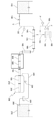
본 발명에 따르면, 처리 대상의 원수에 대한 오존 가스의 주입을 위해 기체 주입기(140)를 사용함으로써 오존 가스 주입 시의 에너지 사용을 줄임과 아울러, 판형 혼합 반응기(170), 다중 분사 반응기(180), 분할 전단 반응기(190), 분사 역방향 혼합 반응기(200)와 같은 저에너지 사용형 기액 접촉 반응기들을 복합적으로 이용하는 것에 의해 접촉 반응 시의 에너지 사용도 줄임으로써, 종래의 인젝터, 스태틱 믹서 조합 방식에 비해 에너지 사용을 50~60% 정도 줄이게 된다.In accordance with the present invention, the use of the
그에 따라, 최소한의 에너지만을 사용하므로, 원수에 에너지를 부여하는 송수 펌프(130)를 생략하거나 저용량의 것으로 이용할 수 있고, 굳이 송수 펌프(130)를 사용하지 않고 원수의 보유 위치 에너지만을 이용하여 수처리를 실시할 수도 있다.Therefore, the
또한, 기체 주입기(140)에서 일부 접촉 반응이 이루어진 후, 저에너지 사용형이면서 효율이 우수한 판형 혼합 반응기(170), 다중 분사 반응기(180), 분할 전단 반응기(190), 분사 역방향 혼합 반응기(200)를 복합적으로 사용하여 접촉 반응을 촉진시키므로, 오존 이용 효율을 99% 이상으로 향상시킬 수 있고 완벽한 정화 처리가 가능함으로써, 종래 방법으로 잘 처리되지 않던 난분해성 물질이 포함된 원수도 처리할 수 있음과 더불어, 잔류 오존량을 줄일 수 있고, 오존 사용량도 종전에 비해 20~30% 감소시켜 오존 발생 비용을 줄일 수 있다.After a partial contact reaction is performed in the
본 발명에 따른 오존 수처리 시스템은, 처리 대상의 원수를 저수하여 공급하는 원수 수조(110)와, 원수 수조(110)로부터 공급되는 원수를 이송하는 송수관(120)과, 수처리에 필요한 에너지를 원수에 부여하여 원수가 가압 이송되도록 하는 송수 펌프(130)와, 이송되는 원수에 주입될 적정 농도의 오존 가스를 발생하여 공급하는 오존 발생기(160)와, 오존 발생기(160)로부터 공급되는 오존 가스를 이송하여 공급하는 오존 공급관(165)과, 오존 공급관(165)을 통해 공급되는 오존 가스를 내부 이송되는 원수에 초미세 기포 형태로 분산 주입하는 기체 주입기(140)와, 기체 주입기(140)로부터 공급되어 이송되는 오존 혼합수 내의 원수와 오존 가스 간의 기액 접촉 반응을 촉진시키는 저에너지 사용형 기액 접촉 반응기와, 후속하여 원수와 오존 가스의 접촉 반응을 촉진하여 반응을 거의 완료하는 주반응기(230)와, 주반응기(230)로부터 배출되는 반응 처리된 처리수를 이송하여 방류하는 방류관(240)을 포함한다.The ozone water treatment system according to the present invention comprises a
원수 수조(110)는 처리 대상의 원수를 유입하여 일시적으로 저수했다가 공급하는 것으로, 원수의 유입량 변동을 극복하고 시스템이 안정적으로 운전될 수 있는 용량으로 선정한다.The
이러한 원수 수조(110)의 일측에는 원수가 배출되는 배출구가 구비되며, 해당 배출구는 송수관(120)의 일단과 연통되게 연결된다.One end of the
여기서, 원수 수조(110) 없이 바로 송수관(120)을 통해 원수가 공급되도록 할 수도 있으나, 원수의 안정적인 공급을 위해서는 원수 수조(110)가 구비되는 것이 바람직하다.Although it is possible to supply the raw water directly through the
송수관(120)은 원수 수조(110)로부터 공급되는 원수를 내부 이송하여 공급하는 배관으로, 일단은 원수 수조(110)의 배출구에 연결되고 타단은 기체 주입기(140)의 선단에 연결되어 원수를 기체 주입기(140)로 공급한다.The
이러한 송수관(120)은 송수되는 원수의 에너지 손실이 최소화될 수 있도록 설계되어 구비된다.The
송수 펌프(130)는 원수에 수처리에 필요한 에너지를 부여하여 원수가 일정 압력 및 유량으로 흡인, 가압 송수되도록 하는 것으로, 유량과 양정에서 운전 효율이 우수한 것을 선정하여 사용한다.The
본 발명에 따르면, 원수에 적은 에너지만을 부여하여도 원활히 수처리 가능하므로, 원수에 에너지를 부여하는 송수 펌프(130)를 생략하거나 작은 용량의 것으로 이용할 수 있으며, 굳이 송수 펌프(130)를 사용하지 않고 원수가 낙차에 의한 위치 에너지만을 갖고 공급되도록 할 수도 있고, 이때 낙차 에너지의 부여는 송수관(120)을 수직되도록 구비시키는 것 등에 의해 구현할 수 있다.According to the present invention, even if only a small amount of energy is applied to the raw water, the water can be smoothly processed. Therefore, the
오존 발생기(160)는 이송되는 원수에 주입될 적정 농도 및 용량의 오존 가스를 발생하여 공급하는 것으로, 별도의 원료 가스 탱크(150)로부터 원료 가스를 공급받아 오존을 발생시킨다.The
이러한 오존 발생기(160)는 원료 가스가 산소 또는 건조 공기인 경우 소정의 압력 상태로 공급되는 원료 가스를 전장(電場)에 통과시켜 산소 분자의 일부가 산소 원자로 분리된 후 분리된 산소 원자가 다른 산소 분자와 결합되도록 하는 것에 의해 오존을 발생시킬 수 있다.When the source gas is oxygen or dry air, the
원료 가스 탱크(150)는 오존 발생에 필요한 원료 가스를 오존 발생기(160)로 공급하는 것으로, 해당 원료 가스는 산소 또는 건조 공기일 수 있다.The raw
오존 공급관(165)은 오존 발생기(160)로부터 공급되는 오존 가스를 내부 이송하여 기체 주입기(140)로 공급하며, 일단은 오존 발생기(160)에 연결되고 타단은 기체 주입기(140)에 연결된다.The
이러한 오존 공급관(165)은 원수 송수압의 일시적인 부조화에 따른 기체 주입기(140)로부터의 원수의 역류를 방지하여 오존 발생기(160)를 보호할 수 있도록 적절히 설계될 수 있다.The
물론, 원수의 역류를 보다 완벽하게 차단하기 위해 오존 공급관(165) 상에는 체크 밸브와 같은 별도의 역류 방지 수단(미도시)이 구비될 수도 있다.Of course, a separate backflow prevention means (not shown) such as a check valve may be provided on the
또한, 상기 기체 주입기(140)로 공급될 오존 가스 이외에 산소가스, 염소가스 또한 발생하여 공급하는 가스 공급관(미도시)을 더 포함하여 구성될 수 있다.Further, the
한편, 원료 가스 탱크(150)와 오존 공급관(165) 간을 직접적으로 연결하여 필요 시점에서 고압 상태의 원료 가스를 바로 기체 주입기(140)로 공급하여 기체 주입기(140)의 오염, 막힘 등을 해결하고 정비하기 위한 원료 가스 공급관(155)이 구비된다.Meanwhile, the raw
도 2는 본 발명의 실시예에 따른 오존 수처리 시스템에 대한 다른 구성도를 나타낸 것으로서, 상기 도 1의 설명에서 나타낸 기체 주입기(140), 판형 혼합 반응기(170), 다중 분사 반응기(180)로 이루어지는 부분에 사이드 스트림(Side stream)의 구성을 추가한 것이다.FIG. 2 shows another configuration of an ozone water treatment system according to an embodiment of the present invention. As shown in FIG. 1, the
이는 기체 주입 방식의 다양한 방법을 추가하기 위하여 이루어진 것이며, 기체 주입기(140)의 종류에 의해 주입 방식이 달라지기도 하지만, 배관의 구성에 의해서도 주입 방식이 달라지기 때문에, 도 1과 같은 풀 스트림 인젝션(Full stream injection) 방식 이외에도 도 2와 같이 사이드 스트림 인젝션(Side stream injection) 방식을 추가하여 나타낸 것이다.Although the injection method is changed depending on the type of the
사이드 스트림 인젝션의 경우 기존 방식과는 다르게 사이드 스트림 비율을 최소화하여 동력비를 최소화하고, 혼합이 잘 이루어지는 특징이 있다.In the case of the side stream injection, unlike the conventional method, the side stream ratio is minimized to minimize the power ratio and mix well.
사이드 스트림은 상기 기체 주입기(140)에 보조 관로(300)를 추가하고, 유입 유량의 일부를 펌프를 이용하여 보조 관로(300)로 흘려 보내고, 이젝터(310)를 이용하여 기체를 주입하는 방식이다.The sidestream is a method in which an
보조 관로(300)의 후단에는 판형 혼합 반응기(170), 다중 분사 반응기(180)를 하나 이상 복합적으로 이용하는 것에 의해 접촉 반응을 촉진시킬 수 있으며, 촉진된 기액수는 다시 기체 주입기(140) 내로 이동되어 혼합되도록 이루어져 있다.The catalytic reaction can be promoted by using at least one of the plate-
도 3 및 도 4는 본 발명의 실시예에 따른 오존 수처리 시스템에 대한 또 다른 구성도를 나타낸 것이다.FIG. 3 and FIG. 4 show another configuration diagram of the ozone water treatment system according to the embodiment of the present invention.
도 3 및 도 4에 도시된 구성 또한 상기 도 1의 설명에서 나타낸 구성과 유사하며, 분할 전단 반응기(190) 후단에 초음파 발생장치(330) 및 초음파 진동장치(320)를 하나 이상 추가하여 나타내었고, 도 4는 도 3의 구성에 덧붙여 방류관(240) 전단에 초음파 발생장치(330)를 연결하고, 방류 수조(270) 전단에 관수로형 체류조(340)를 부가하여 나타낸 것이다.3 and 4 are also similar to those shown in FIG. 1, and one or more
상기 설치되는 초음파 발생장치(330)는 반응기의 촉진반응을 좀 더 촉진시킨다. 또한, 상기 초음파 발생장치(330) 후단에 초음파 진동장치(320)를 설치하여, 잔류 오존의 반응을 극대화하여 후단 오존 냄새에 의한 피해를 최소화할 수 있다.The installed
도 4의 관수로형 체류조(340)는 기체주입, 접촉 반응중인 처리수를 기체와의 반응을 더욱 촉진시키기 위해 필요하다.4 is required to further promote the reaction of the treated water in the gas injection and contact reaction with the gas.
기존 방류 수조(270) 전단에 전체 구조물이 밀폐된 관수로형 체류조(340)를 설치하고, 상기 관수로형 체류조(340) 내부에는 반응을 촉진시키기 위한 와류를 형성할 수 있는 상하, 좌우 도류벽을 설치한다. 관수로형 체류조(340)는 기체의 외부 유출 없이, 유체와의 반응을 지속적으로 시킬 수 있도록 밀폐되는 것을 특징으로 한다.A water tank (340) in which an entire structure is sealed is provided at a front end of a conventional water discharge tank (270). In the water storage tank (340) Install a flow-through wall. The water tub
도 3 및 도 4의 구성에는 공통적으로, 풀 스트림 인젝션(Full stream injection) 방식 및 사이드 스트림 인젝션(Side stream injection) 방식의 후단에 초음파 발생장치(330) 및 초음파 진동장치(320)를 설치하여, 미세 기포로 주입된 오존이 판형 혼합 반응기(170), 다중 분사 반응기(180)를 복합적으로 이용하는 것에 의해 접촉 반응을 촉진시킨 후, 초음파 발생장치(330) 및 초음파 진동장치(320)를 통해 초음파 공동 현상이 일어나고, 더욱 접촉 반응이 촉진되어져, 오존과의 반응 촉진 및 초음파에 의한 수처리 효과를 얻을 수 있다.3 and 4, an ultrasonic
또한, 방류관(240) 전단에 초음파 발생장치(330)를 추가 설치하여, 전단에서 반응되지 않은 오존의 반응을 극대화하여, 방류 수조(270) 처리 후에도 오존에 의한 냄새 피해를 최소화할 수 있다.In addition, the
기체 주입기(140)는 오존 공급관(165)을 통해 공급되는 오존 가스의 자체 압력을 이용하여 내부 이송되는 원수의 수중으로 오존 가스를 분산되게 주입한다.The
상기 기체 주입기의 종류는 멤브레인형 기체 주입기, 마이크로버블형 기체 주입기, 타공형 주입기 등의 주관로 내부 관로 면적 전체에 균일하게 직접 주입할 수 있는 STS304, STS316, 아스텔루이, PP, PE 등의 재질의 기체 주입기를 포함할 수 있다.Examples of the gas injector include materials such as STS304, STS316, Austelite, PP, and PE which can be uniformly injected directly into the main channel of the main pipe such as a membrane type gas injector, a micro bubble type gas injector, Of the gas injector.
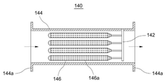
구체적으로, 기체 주입기(140)는 도 5에 나타낸 바와 같이, 송수관(120)으로부터 공급되는 원수를 내부 이송하는 메인 배관(144)과, 메인 배관(144) 내에 소 직경의 관 형태로 구비되고 그 외측면 상에 전반적으로 형성된 수많은 초미세 분사공(146a)을 통해 오존 가스를 초미세 기포 형태로 수중 분사하는 다공관(146) 및 외부의 오존 공급관(165)과 내부의 다공관(146)을 연결하여 오존 가스를 공급하는 가스 연결관(142)으로 이루어진다.5, the
여기서, 메인 배관(144)은 양단이 개방되며, 그 양단에는 배관 연결을 위한 플랜지부(144a)가 형성된다.Here, both ends of the
그리고, 다공관(146)은 오존 가스를 초미세 기포 형태로 만들어 분산되게 분사하는 것으로, 도시된 바와 같이 길이 방향을 따라 길게 구비되며, 다수개가 균등하게 배치되도록 구비될 수 있다.In addition, the
이러한 다공관(146)은 가스 연결관(142)과 연결되는 부분을 제외하고는 폐쇄되도록 구비되며, 그 외측면 상에 초미세 분사공(146a)들이 전반적으로 균일하게 배치되도록 구비된다.The
따라서, 수많은 초미세 분사공(146a)을 통해 오존 가스를 초미세 기포 형태로 분산되게 주입하므로, 오존 가스의 초미세 기포가 내부 이송되는 원수 내에 신속하면서 균일하게 혼합, 용해될 수 있고, 그 결과 원수와 오존 가스 간의 접촉 반응을 극대화시킬 수 있다.Therefore, since the ozone gas is dispersedly injected in the form of ultrafine bubbles through the numerous
이러한 기체 주입기(140)를 이용하면, 주입되는 오존 가스의 압력 손실을 200mbar 이하로 실현할 수 있음과 더불어, 무엇보다도 오존 가스 주입에 따른 원수의 에너지 사용을 최소화할 수 있고, 즉 기존의 인젝터를 이용하는 경우와 비교하여 원수의 에너지 사용을 1/20 정도로 감소시킬 수 있다.The use of such a
바람직하게, 에너지 사용을 최소화시키고 혼합 및 접촉 반응을 최대화시키기 위해 다공관(146) 상에 형성되는 각 초미세 분사공(146a)의 크기는 10㎛ 이하로 구현될 수 있다.Preferably, the size of each
저에너지 사용형 기액 접촉 반응기는 이송되는 오존 혼합수의 에너지 사용을 최소화하면서 원수와 오존 가스 간의 접촉 반응을 촉진시키는 것으로, 구체적으로 판형 혼합 반응기(170), 다중 분사 반응기(180) 및 분할 전단 반응기(190)를 사용한다.The low-energy-use gas-liquid contact reactor promotes the contact reaction between the raw water and the ozone gas while minimizing the energy use of the ozone mixed water to be transferred. Specifically, the
판형 혼합 반응기(170)는 오존 혼합수의 유로를 변경시키고 유속을 가속시키며, 오존 혼합수를 분할 및 전단시켜 접촉 반응을 촉진시킨다.The plate
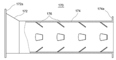
이러한 판형 혼합 반응기(170)는 도 6에 나타낸 바와 같이, 점차 직경이 축소되는 관 형태로 구비되어 기체 주입기(140)로부터 공급되어 이송되는 오존 혼합수의 유로를 변경시키고 유속을 가속시키는 유입 축소관(172)과, 유입 축소관(172) 다음에서 오존 혼합수를 계속하여 이송시키는 후방 배관(174)과, 후방 배관(174)의 내측면 상에 돌출되도록 다수개 구비되어 오존 혼합수의 방향 및 유속을 변경시켜 난류 현상을 일으키고 오존 혼합수를 일부 분할 및 전단시키는 돌출 부재(176)로 이루어진다.As shown in FIG. 6, the plate-
여기서, 판형 혼합 반응기(170)의 양단을 이루는 유입 축소관(172)의 선단과 후방 배관(174)의 후단에는 배관 연결을 위한 플랜지부(172a, 174a)가 형성된다.
유입 축소관(172)은 선단으로부터 후단으로 갈수록 점차 직경이 축소되도록 형성되어 이송되는 오존 혼합수의 유속을 가속시키고 유로를 변경시켜 원수와 오존 가스 간의 접촉 반응을 촉진시킨다.The
돌출 부재(176)는 후방 배관(174)의 내측면 상에 다수개가 균등하게 배치되도록 구비되는 것으로, 이송되는 오존 혼합수가 다수개의 돌출 부재(176)에 충돌되어 그 방향 및 유속이 변경되고 난류 현상이 발생되도록 함과 아울러, 그 일부가 분할 및 전단되도록 함으로써, 원수와 오존 가스 간의 접촉 반응이 재차 촉진되도록 한다.A plurality of projecting
이러한 돌출 부재(176)는 도시된 바와 같이, 경사진 작은 판 형태로 구현될 수 있다.This protruding
다중 분사 반응기(180)는 판형 혼합 반응기(170)에서 반응 처리된 오존 혼합수를 계속 이송하면서 가속, 분할, 전단, 와류, 난류 및 역류시켜 접촉 반응을 재차 촉진시킨다.The
이러한 다중 분사 반응기(180)는 도 7에 나타낸 바와 같이, 판형 혼합 반응기(170)로부터 공급되는 오존 혼합수를 내부 이송하는 메인 배관(182)과, 메인 배관(182) 내에 오존 혼합수의 흐름 방향과 직교되는 방향으로 반복되게 구비되는 판 형태의 것으로 다수개의 관통공(184a)을 갖는 차단 다공판(184)으로 이루어진다.7, the
여기서, 메인 배관(182)의 양단은 개방되며, 그 양단에는 배관 연결을 위한 플랜지부(182a)가 형성된다.Both ends of the
차단 다공판(184)은 메인 배관(182)의 길이 방향을 따라 이격되도록 다수개가 반복되게 구비된다.The cut-off
따라서, 이송되는 오존 혼합수는 차단 다공판(184)에 순차적으로 부딪혀 흐름이 변경 또는 역류되거나 유속이 변화되고, 관통공(184a)을 통과하면서 유속이 가속됨과 아울러 일부 분할되며, 그에 따른 강력한 전단 작용 및 와류, 난류, 역류 작용에 의해 원수와 오존 가스 간의 접촉 반응이 촉진될 수 있다.Therefore, the ozone mixed water being conveyed is sequentially hit against the blocking
이러한 다중 분사 반응기(180)는 기존의 스태틱 믹서 등에 비해 10배 정도 반응 효율이 우수한 반면, 에너지 소비는 83% 수준으로 매우 낮아 에너지 사용을 대폭 줄일 수 있다.The
정리하면, 기체 주입기(140)와 판형 혼합 반응기(170)를 통과하면서 원수 내의 오존 가스의 분포가 매우 균일해지며, 다중 분사 반응기(180)를 통과하면서 원수와 오존 가스 간의 접촉 반응이 본격화된다.In summary, the distribution of the ozone gas in the raw water becomes very uniform by passing through the
분할 전단 반응기(190)는 다중 분사 반응기(180)에서 반응 처리된 오존 혼합수를 계속 이송하면서 분할, 전단, 반전, 난류화시켜 접촉 반응을 재차 촉진시킨다.The
이러한 분할 전단 반응기(190)는 도 8에 나타낸 바와 같이, 다중 분사 반응기(180)로부터 공급되는 오존 혼합수를 내부 이송하는 메인 배관(192)과, 메인 배관(192) 내에 길이 방향을 따라 수직 방향의 것과 수평 방향의 것이 반복되도록 구비되어 오존 혼합수를 계속 양분하여 분할하는 만곡된 판 형태의 나선형 블레이드(194)로 이루어진다.8, the divided
여기서, 메인 배관(192)의 양단은 개방되며, 그 양단에는 배관 연결을 위한 플랜지부(192a)가 형성된다.Here, both ends of the
따라서, 내부 이송되는 오존 혼합수는 각 나선형 블레이드(194)를 통과할 때마다 양분되도록 계속 분할되며, 나선형 블레이드(194)의 만곡된 형태에 따라 그 방향 및 유속이 가변되고, 각 나선형 블레이드(194)의 방향이 순차적으로 변경됨에 따라 반전 및 변환되어, 강력한 전단 및 난류 작용에 의해 원수와 오존 가스의 접촉 반응이 촉진될 수 있다.Accordingly, the internally transported ozone mixed water is continually divided so that it is bisected each time it passes through each
여기서, 나선형 블레이드(194)의 개수를 n이라고 하면, 오존 혼합수가 분할되는 수는 2ⁿ이 된다.Here, when the number of the
이러한 분할 전단 반응기(190)는 다소 큰 에너지 사용을 유발하나 반응 효율 면에서 양호하다.This split
이상과 같은 판형 혼합 반응기(170), 다중 분사 반응기(180) 및 분할 전단 반응기(190)는 모두 기존의 스태틱 믹서 등과 비교하여 오존 혼합수의 에너지 사용을 대폭 줄일 수 있는 저에너지 사용형 기액 접촉 반응기로서, 세 종류 반응기(170, 180, 190)의 채택 여부, 배치 순서 및 구비 대수는 선택적일 수 있다.The plate-
주반응기(230)는 판형 혼합 반응기(170), 다중 분사 반응기(180) 및 분할 전단 반응기(190)를 거치면서도 아직 미처 반응되지 않은 원수와 오존 가스 간의 접촉 반응을 촉진시켜 반응을 거의 완료시킨다.The
이러한 주반응기(230)는 분사 역방향 혼합 반응기(200)를 필수적으로 내장하며, 해당 분사 역방향 혼합 반응기(200)의 전방에 상기한 저에너지 사용형 기액 접촉 반응기를 선택적으로 내장한다.The
도면 상에는 내장되는 저에너지 사용형 기액 접촉 반응기로서 분할 전단 반응기(190)를 채택한 경우를 나타낸다.The figure shows a case in which a divided
주반응기(230)는 상대적으로 큰 직경을 가지며 분사 역방향 혼합 반응기(200)로부터 배출되는 처리수를 내부 수용한 다음 배출하는 반응 탱크(210)와, 반응 탱크(210) 내에 내장되는 분할 전단 반응기(190) 및 분사 역방향 혼합 반응기(200)와, 반응 탱크(210) 내에 수용된 오존 혼합수 내에 잔존하는 산소 가스와 같은 배가스를 분리하여 배출하는 기액 분리 수단(220)으로 이루어진다.The
여기서, 분사 역방향 혼합 반응기(200)는 분사 및 역류 혼합을 통해 접촉 반응을 재차 촉진시킨다.Here, the spray backward mixing
이러한 분사 역방향 혼합 반응기(200)는 도 9에 나타낸 바와 같이, 오존 혼합수가 유입되는 선단 측이 개방되고 유출되는 후단 측은 단면이 점차 축소되어 중심부에 분사공(222b)이 형성되는 분사 배관(222)과, 분사 배관(222)으로부터 분사되는 오존 혼합수를 역류시키는 오목 형태의 오목 반사판(224a)이 후단 측에 구비되고 일측 측벽에 반응 처리된 처리수의 배출을 위한 배출구(224b)를 갖는 후방 배관(224)으로 이루어진다.As shown in FIG. 9, the injection backward mixing
여기서, 분사 배관(222)의 선단은 개방되며, 그 선단에는 배관 연결을 위한 플랜지부(222a)가 형성된다.Here, the tip of the
따라서, 분할 전단 반응기(190)로부터 공급되는 오존 혼합수는 분사 배관(222) 내부를 통과하여 분사공(222b)에서 분사되는 때에 오존 혼합수의 방향 및 유속이 변경되어 난류 작용이 발생되고, 또한 분사된 오존 혼합수가 후방 배관(224)의 내부를 통과하여 오목 반사판(224a)에 부딪히는 때에 난류, 와류 및 역류 작용이 발생되어 접촉 반응이 촉진된 다음, 접촉 반응이 거의 완료된 처리수는 후방 배관(224)의 일측 측벽에 형성된 배출구(224b)를 통해 배출되어 반응 탱크(210) 내로 수용된다.Therefore, when the ozone mixed water supplied from the divided
이와 같은 분사 역방향 혼합 반응기(200)도 기존의 스태틱 믹서 등과 비교하여 오존 혼합수의 에너지 손실을 줄일 수 있는 저에너지 사용형 기액 접촉 반응기이다.The spray backward mixing
기액 분리 수단(220)은 기액 접촉 반응에 따라 발생되어 처리수 내에 잔존하는 산소 가스와 같은 배가스를 반응 탱크(210) 내의 처리수로부터 분리하여 배출시키는 것으로, 반응 탱크(210) 내의 압력을 유지시킨다.The gas-liquid separating means 220 separates and discharges exhaust gas such as oxygen gas generated in the gas-liquid contact reaction and remaining in the treated water from the treated water in the
이러한 기액 분리 수단(220)으로는 반응 탱크(210) 내의 상부 공간에 모이는 배가스를 선택적으로 방출시킬 수 있는 체크 밸브로 구현될 수 있다.The gas-liquid separating means 220 may be implemented as a check valve capable of selectively discharging exhaust gas collected in an upper space of the
방류관(240)은 주반응기(230)의 반응 탱크(210)로부터 배출되는 처리수를 계속 이송하여 방류시키는 것으로, 반응 탱크(210)로부터 길게 연장된다.The
이러한 방류관(240)은 이송되는 처리수의 에너지 손실이 최소화될 수 있도록 설계되어 구비된다.The
나아가, 본 발명에 따르면, 처리수가 방류관(240)을 통해 목적하는 개소까지 이송되어 방류될 수 있으나, 바람직하게는 방류관(240)을 통해 방류되는 처리수를 최종적으로 수집하여 저수하도록 방류 수조(270)가 더 구비될 수 있다.Further, according to the present invention, the treated water can be transferred to and discharged to a desired location through the
방류 수조(270)는 처리수를 최종 수집하여 안전하게 배출되도록 하는 것으로, 처리수의 유입량 및 유출량 변동을 극복하고 시스템이 안정적으로 운전될 수 있는 용량으로 선정된다.The
그리고, 방류관(240)을 통한 처리수의 방류에 따라 주반응기(230) 내의 압력이 저하되는 것을 최소화시키기 위해 방류관(240) 상에는 압력 유지 수단(250)이 구비될 수 있다.A pressure holding means 250 may be provided on the
이러한 압력 유지 수단(250)은 방류관(240)의 내부 유로를 축소시키는 구조를 통해 구현될 수 있다.The pressure maintaining means 250 may be implemented through a structure for reducing the internal flow path of the
또한, 방류 수조(270) 내의 수중으로 처리수를 분사하여 방류함으로써 처리수가 잔류 에너지 및 오존을 이용하여 방류 수조(270) 내부에서 마무리 반응될 수 있도록 하기 위해 방류관(240)의 끝단에는 분사 수단(260)이 구비될 수 있다.In order to allow the treated water to be finely reacted in the
이상, 상술한 바와 같이 원수 수조(110)로부터 방류 수조(270)까지 하나의 라인 형태로 이어지는 구성은 원수를 계속적으로 이송하면서 1회 처리하는 방식에 대한 것이다.As described above, the configuration in which the raw water from the
한편, 본 발명에 따르면, 원수 수질 및 처리 목표 등에 따라 2회 이상 반복 처리하는 방식을 구현할 수도 있으며, 이러한 반복 처리 방식의 구성을 도 10에 나타낸다.On the other hand, according to the present invention, it is also possible to implement a method of performing repetitive processing twice or more in accordance with raw water quality and processing target, and the configuration of such a repetitive processing method is shown in Fig.
반복 처리 방식에서는 주반응기(230)로부터 방류 수조(270)로 처리수를 이송하는 방류관(240)의 도중에서 분기되어 처리수의 일부를 원수 수조(110) 측으로 순환시키기 위한 순환관(280)이 더 구비된다.The
즉, 주반응기(230)에서 반응 처리된 후 이송되는 처리수는 도중에서 방류관(240)과 순환관(280)으로 나누어져 각각 방류 수조(270)와 원수 수조(110) 측으로 공급된다.That is, the treated water after being subjected to the reaction treatment in the
그리고, 재처리를 위해 순환관(280)을 통해 공급되는 처리수와 원수 수조(110)로부터 공급되는 원수를 함께 흡입, 혼합하여 송수관(120)으로 공급할 수 있도록 원수 수조(110) 내에는 혼합 공급기(290)가 더 구비된다.The
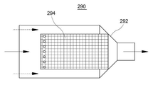
혼합 공급기(290)는 도 11에 나타낸 바와 같이, 유입되는 선단 측이 직경이 큰 대경부로 형성되고 유출되는 측이 상대적으로 직경이 작은 소경부로 일체화되게 형성되는 혼합 배관(292)과, 소경부의 입구 측을 덮도록 대경부 내에 중심부에 구비되어 내부 이송되는 처리수와 원수에 함유된 이물질을 걸러내는 스트레이너(294)로 이루어진다.As shown in FIG. 11, the
따라서, 순환관(280)의 끝단은 혼합 배관(292)의 대경부 내로 삽입되어 스트레이너(294)에 접촉됨으로써 스트레이너(294)로 직접 처리수를 공급하며, 혼합 배관(292)의 대경부와 스트레이너(294)의 사이 공간을 통해 원수 수조(110) 내의 원수가 공급되어 처리수와 원수가 혼합된 다음 송수관(120)으로 공급된다.The end of the
덧붙여, 미도시하였으나, 본 발명에 따른 오존 수처리 시스템은 자동 운전이 가능하도록 전반적인 작동 제어를 실시하는 제어 패널을 더 구비할 수 있고, 상기한 송수관(120), 오존 공급관(165), 원료 가스 공급관(155), 방류관(240) 및 순환관(280) 상에는 유체의 공급을 개폐하기 위한 밸브 수단(V)과, 유체의 압력 및 유량을 측정하기 위한 유압계(P) 및 유량계(F)들이 구비될 수 있다.In addition, although not shown, the ozone water treatment system according to the present invention may further include a control panel for performing overall operation control so as to enable automatic operation. The
또한 덧붙여, 각 엘레먼트 및 그에 부속되는 부속 엘레먼트의 크기, 개수, 구조 등은 처리 대상의 원수 수질 및 수량, 목표 수질, 오존 가스 주입량 등을 고려하여 적절히 결정될 수 있다.In addition, the size, number and structure of each element and the attached elements attached thereto can be appropriately determined in consideration of the raw water quality and quantity to be treated, the target water quality, the amount of ozone gas injected, and the like.
이상과 같은 구성을 가지는 본 발명에 따른 저에너지를 사용하는 오존 수처리 시스템의 작용에 대해 이하 설명한다.The operation of the ozone water treatment system using the low energy according to the present invention having the above-described structure will be described below.
먼저, 송수 펌프(130)가 작동되면, 원수 수조(110) 내에 저수된 처리 대상의 원수가 흡입되어 송수관(120)을 통해 이송된 다음 기체 주입기(140)로 공급된다.First, when the
이때, 원수는 송수 펌프(130)에 의해 수처리에 필요한 에너지를 부여받는다.At this time, raw water is supplied with energy necessary for water treatment by the
물론, 송수 펌프(130)를 사용하지 않고 원수가 낙차에 의한 위치 에너지를 부여받고 송수관(120)을 통해 공급되도록 할 수도 있다.Of course, it is also possible that the raw water is supplied with the potential energy due to the drop and supplied through the
이어서, 기체 주입기(140)로 공급된 원수는 기체 주입기(140)의 내부를 흐르며, 이때 오존 발생기(160)에서 발생된 다음 적정 압력을 갖은 상태로 오존 공급관(165)을 통해 공급되는 오존 가스가 해당 기체 주입기(140) 내의 다공관(146)을 통해 초미세 기포 형태로 분산되게 분사되어 내부를 흐르는 원수에 주입되어 혼합된다.The raw water supplied to the
그 후, 오존 혼합수는 계속하여 판형 혼합 반응기(170)로 공급되어 판형 혼합 반응기(170)에서 가속, 난류, 분할, 전단되어 원수와 오존 가스 간의 접촉 반응이 이루어진다.Thereafter, the ozone mixed water is continuously supplied to the plate-
그 다음, 계속하여 오존 혼합수는 다중 분사 반응기(180)로 공급되어 다중 분사 반응기(180)에서 가속, 분할, 전단, 와류, 난류, 역류되어 원수와 오존 가스 간의 접촉 반응이 재차 이루어진다.Subsequently, the ozone mixed water is supplied to the
이어서, 오존 혼합수는 계속하여 분할 전단 반응기(190)로 공급되어 분할 전단 반응기(190)에서 분할, 전단, 반전, 난류화되어 접촉 반응이 재차 이루어진다.Then, the ozone mixed water is continuously supplied to the divided
그 후, 오존 혼합수는 다시 한번 다중 분사 반응기(180)를 통과하면서 반응이 촉진된 다음, 주반응기(230)로 공급된다.Thereafter, the ozone mixed water is once again passed through the
주반응기(230)로 공급된 오존 혼합수는 해당 주반응기(230)에 내장된 분할 전단 반응기(190)를 통과하여 재차 반응이 촉진된 후, 분사 역방향 혼합 반응기(200)로 공급되어 분사 역방향 혼합 반응기(200)에서 가속, 난류, 와류, 역류되어 재차 반응이 이루어진다.The ozone mixed water supplied to the
그 다음, 분사 역방향 혼합 반응기(200)로부터 배출되는 오존 혼합수는 주반응기(230)의 반응 탱크(210) 내로 배출되어 수용되며, 반응 탱크(210) 내에서 체재하는 동안 처리수 내에 잔존하는 배가스가 기액 분리 수단(220)에 의해 분리 배출되어 제거된다.The mixed ozone water discharged from the spray backward mixing
그 후, 주반응기(230)까지 거쳐 거의 수처리가 완료된 처리수는 이후 주반응기(230)의 반응 탱크(210)로부터 배출되어 방류관(240)을 통해 이송된 다음, 해당 방류관(240)의 끝단에 구비되어 있는 분사 수단(260)을 통해 방류 수조(270) 내의 수중으로 방류되며, 이어서 방류 수조(270) 내에서 잔류 에너지 및 잔류 오존을 이용하여 마무리 반응된다.The treated water which has been almost completely treated through the
그리고, 반복 처리 방식의 경우에는 방류관(240)을 통해 이송되는 처리수 중의 일부가 도중에서 분기되는 순환관(280)으로 나뉘어져 원수 수조(110) 측으로 공급되며, 재처리를 위해 순환된 처리수는 혼합 공급기(290)에서 원수와 함께 흡입, 혼합된 다음 다시 송수관(120)을 통해 송수된다.In the case of the repetitive processing method, a part of the treated water fed through the
이로써, 본 발명에 의하면, 기체 주입기(140)를 이용하여 오존 가스 주입 시의 에너지 사용을 대폭 줄일 수 있고, 또한 저에너지 사용형 기액 접촉 반응기들을 사용하여 접촉 반응 시의 에너지 사용도 대폭 줄일 수 있으므로, 결과적으로 처리 비용을 절감시킬 수 있다.Thus, according to the present invention, it is possible to greatly reduce the energy consumption at the time of injecting ozone gas using the
또한, 판형 혼합 반응기(170), 다중 분사 반응기(180), 분할 전단 반응기(190) 및 분사 역방향 혼합 반응기(200)와 같은 저에너지 손실형 반응기들을 복합적으로 사용하고, 필요에 따라 처리수의 일부를 순환시켜 재처리하므로, 완벽한 수처리를 기할 수 있다.It is also possible to use a combination of low energy loss type reactors such as a plate
그리고, 전 과정을 거치는데 소요되는 처리 시간도 종래의 산기 방식에 비해 약 1/10 정도로 단축될 수 있어, 처리 생산성도 우수할 수 있다.In addition, the processing time required to pass the entire process can be shortened to about 1/10 of that in the conventional generation system, and the processing productivity can be also excellent.
이상, 상기 내용은 본 발명의 바람직한 일 실시예를 단지 예시한 것으로 본 발명의 당업자는 본 발명의 요지를 변경시킴이 없이 본 발명에 대한 수정과 변경을 가할 수 있음을 인지해야 한다.It will be appreciated by those skilled in the art that changes may be made to the present invention without departing from the spirit and scope of the invention as defined by the appended claims.
110 : 원수 수조 120 : 송수관
130 : 송수 펌프 140 : 기체 주입기
142 : 가스 연결관 144 : 메인 배관
144a : 플랜지부 146 : 다공관
146a : 분사공 150 : 원료 가스 탱크
155 : 원료 가스 공급관 160 : 오존 발생기
165 : 오존 공급관 170 : 판형 혼합 반응기
172 : 유입 축소관 172a : 플랜지부
174 : 후방 배관 174a : 플랜지부
176 : 돌출 부재 180 : 다중 분사 반응기
182 : 메인 배관 182a : 플랜지부
184 : 차단 다공판 184a : 관통공
190 : 분할 전단 반응기 192 : 메인 배관
192a : 플랜지부 194 : 나선형 블레이드
200 : 분사 역방향 혼합 반응기 222 : 분사 배관
222a : 플랜지부 222b : 분사공
224 : 후방 배관 224a : 오목 반사판
224b : 배출구 210 : 반응 탱크
220 : 기액 분리 수단 230 : 주반응기
240 : 방류관 250 : 압력 유지 수단
260 : 분사 수단 270 : 방류 수조
280 : 순환관 290 : 혼합 공급기
292 : 혼합 배관 294 : 스트레이너
300 : 보조 관로 310 : 이젝터
320 : 초음파 진동장치 330 : 초음파 발생장치
340 : 관수로형 체류조
F : 유량계 P : 압력계
V : 밸브 수단110: raw water tank 120: water pipe
130: water pump 140: gas injector
142: gas connection pipe 144: main pipe
144a: flange portion 146:
146a: Spout hole 150: Raw material gas tank
155: source gas supply pipe 160: ozone generator
165: ozone supply pipe 170: plate type mixing reactor
172:
174:
176: projecting member 180: multi-injection reactor
182:
184:
190: Split shear reactor 192: Main piping
192a: flange portion 194: helical blade
200: injection reverse mixing reactor 222: injection piping
222a:
224:
224b: Outlet 210: Reaction tank
220: gas-liquid separating means 230: main reactor
240: discharge pipe 250: pressure holding means
260: injection means 270: discharge water tank
280: Circulation tube 290: Mixing feeder
292: Mix piping 294: Strainer
300: auxiliary conduit 310: ejector
320: ultrasonic vibrator 330: ultrasonic generator
340: Irrigation type residence tank
F: Flow meter P: Pressure gauge
V: valve means
Claims (25)
상기 송수관으로부터 공급되어 이송되는 원수에 오존 가스를 초미세 기포 형태로 분산 주입하는 기체 주입기와,
상기 기체 주입기로부터 공급되어 이송되는 오존 혼합수 내의 상기 원수와 상기 오존 가스의 접촉 반응을 촉진시키는 저에너지 사용형 기액 접촉 반응기, 및 반응 처리된 처리수를 계속 이송하여 반응촉진을 시키는 관수로형 체류조와, 방류하는 방류관을 포함하고,
상기 관수로형 체류조는, 반응을 촉진시키기 위해 와류를 형성할 수 있는 상하 좌우 또는 상하 도류벽을 포함하는 것을 특징으로 하는 저에너지를 사용하는 오존 수처리 시스템.A feed water pipe through which raw water to be treated is fed and supplied with energy,
A gas injector for dispersively injecting ozone gas in the form of ultrafine bubbles into the raw water supplied from the water pipe,
A low-energy-use gas-liquid contact reactor for promoting the contact reaction between the raw water and the ozone gas supplied from the gas injector and transported in the ozone mixed water, and a water- , And a discharge pipe for discharge,
Wherein the water-in-oil-type bath comprises upper, lower, right, left, and upper cooling walls capable of forming a vortex for promoting the reaction.
상기 저에너지 사용형 기액 접촉 반응기는,
판형 혼합 반응기, 다중 분사 반응기, 분할 전단 반응기 중에서 선택되는 어느 하나 이상의 조합으로 이루어지는 것을 특징으로 하는 저에너지를 사용하는 오존 수처리 시스템.The method according to claim 1,
The low-energy-use gas-liquid contacting reactor comprises:
A plate-type mixing reactor, a multi-injection reactor, and a divided shear reactor. The ozone water treatment system using low energy.
상기 송수관을 통해 공급되는 상기 원수는,
낙차에 의한 위치 에너지에 의해 가압 이송되는 것을 특징으로 하는 저에너지를 사용하는 오존 수처리 시스템.3. The method according to claim 1 or 2,
Wherein the raw water supplied through the water pipe comprises:
And is pressurized and transported by the potential energy caused by the drop.
상기 원수에 에너지를 부여하고 송수되도록 하는 송수 펌프를 더 포함하는 저에너지를 사용하는 오존 수처리 시스템.3. The method according to claim 1 or 2,
Further comprising a water supply pump for supplying energy to the raw water and for sending and receiving water to the ozone water treatment system.
상기 원수를 저수하고 상기 송수관으로 공급하는 원수 수조를 더 포함하는 저에너지를 사용하는 오존 수처리 시스템.3. The method according to claim 1 or 2,
And a raw water tank for storing the raw water and supplying the raw water to the water pipe.
상기 기체 주입기로 공급될 상기 오존 가스를 발생하여 공급하는 오존 발생기, 및 상기 오존 발생기로부터 공급되는 상기 오존 가스를 상기 기체 주입기로 이송하여 공급하는 오존 공급관을 더 포함하는 저에너지를 사용하는 오존 수처리 시스템.3. The method according to claim 1 or 2,
An ozone generator for generating and supplying the ozone gas to be supplied to the gas injector, and an ozone supply pipe for transferring and supplying the ozone gas supplied from the ozone generator to the gas injector.
상기 기체 주입기로 공급될 오존 가스 이외에 산소가스, 염소가스 또한 발생하여 공급하는 가스 공급관을 더 포함하는 저에너지를 사용하는 오존 수처리 시스템.3. The method according to claim 1 or 2,
Further comprising a gas supply pipe for generating and supplying oxygen gas and chlorine gas in addition to ozone gas to be supplied to the gas injector.
상기 기체 주입기의 종류는 멤브레인형 기체 주입기, 마이크로버블형 기체 주입기, 타공형 주입기의 주관로 내부 관로 면적 전체에 균일하게 직접 주입할 수 있는 STS304, STS316, STS316L, 아스텔루이, PP, PE 재질의 기체 주입기를 포함하는 저에너지를 사용하는 오존 수처리 시스템.3. The method according to claim 1 or 2,
The type of the gas injector is STS304, STS316, STS316L, Astelouis, PP, PE which can be uniformly injected directly into the main channel of the main pipe of the membrane type gas injector, micro bubble type gas injector, An ozone water treatment system using low energy including a gas injector.
미세기포로 주입된 오존가스가 판형 혼합 반응기, 다중 분사 반응기를 복합적으로 이용하는 것에 의해 접촉 반응을 촉진시킨 후, 초음파 발생장치를 통해 초음파 공동현상이 일어나고, 더욱 접촉반응이 촉진되어져, 오존과 원수의 2차 촉진 반응 및 초음파에 의한 수처리 효과를 동시에 얻을 수 있는 저에너지를 사용하는 오존 수처리 시스템.3. The method according to claim 1 or 2,
The ozone gas injected into the micropores accelerates the contact reaction by using the plate-type mixing reactor and the multi-jet reactor in combination, the ultrasonic cavitation occurs through the ultrasonic generator, and further the contact reaction is promoted. Ozone water treatment system using low energy which can simultaneously obtain tea-promoting reaction and water treatment effect by ultrasonic wave.
상기 기체 주입기에 보조 관로를 추가하고, 유입 유량의 일부를 펌프를 이용하여 보조 관로로 흘려 보내고, 이젝터를 이용하여 기체를 주입시키는 사이드 스트림 구성을 더 포함하고,
보조 관로의 후단에는 판형 혼합 반응기, 다중 분사 반응기를 하나 이상 복합적으로 이용하는 것에 의해 접촉 반응을 촉진시킬 수 있으며, 촉진된 기액수는 다시 기체 주입기 내로 이동되어 혼합되도록 하는 것을 특징으로 하는 오존 수처리 시스템.3. The method according to claim 1 or 2,
Further comprising a side stream arrangement for adding an auxiliary conduit to the gas injector, flowing a portion of the inlet flow rate to the auxiliary conduit using a pump, and injecting the gas using the ejector,
Wherein a contact reaction can be promoted by using at least one of a plate type mixing reactor and a multipurpose reactor in a rear stage of the auxiliary pipeline, and the promoted base liquid is moved into the gas injector again for mixing.
상기 방류관에서 방류되는 상기 처리수를 저수하는 방류 수조, 및 상기 방류관의 끝단에 구비되어 상기 방류 수조 내의 수중으로 상기 처리수를 분사하는 분사 수단을 더 포함하는 저에너지를 사용하는 오존 수처리 시스템.3. The method according to claim 1 or 2,
A discharge water tank for storing the treated water discharged from the discharge pipe, and a spraying means provided at an end of the discharge pipe for spraying the treated water into the water in the discharge water tank.
상기 저에너지 사용형 기액 접촉 반응기로부터 공급되는 상기 오존 혼합수 내의 상기 원수와 상기 오존 가스의 접촉 반응을 촉진하며 반응 처리된 상기 처리수를 상기 방류관으로 공급하는 주반응기를 더 포함하는 저에너지를 사용하는 오존 수처리 시스템.3. The method according to claim 1 or 2,
Further comprising a main reactor for promoting a contact reaction between the raw water in the ozone mixed water supplied from the low-energy-use gas-liquid contact reactor and the ozone gas and supplying the treated water subjected to the reaction treatment to the discharge tube Ozone water treatment system.
상기 주반응기 후단과 방류관 전단에 선택적으로 초음파 발생장치를 설치하여, 전처리 과정에서 반응되지 않은 오존의 반응을 극대화 및 잔류 오존을 제로화하여, 오존에 의한 냄새피해를 최소화할 수 있도록 하는 저에너지를 사용하는 오존 수처리 시스템.13. The method of claim 12,
An ultrasonic generator is selectively installed at the downstream end of the main reactor and at the upstream end of the discharge pipe to maximize the reaction of unreacted ozone and zero residual ozone in the pretreatment process and to use low energy to minimize odor damage caused by ozone Ozone water treatment system.
상기 저에너지 사용형 기액 접촉 반응기는,
상기 판형 혼합 반응기, 상기 다중 분사 반응기, 상기 분할 전단 반응기, 상기 다중 분사 반응기의 순서로 구비되는 것을 특징으로 하는 저에너지를 사용하는 오존 수처리 시스템.3. The method of claim 2,
The low-energy-use gas-liquid contacting reactor comprises:
Wherein the apparatus is provided in the order of the plate-type mixing reactor, the multi-injection reactor, the divided shear reactor, and the multi-injection reactor.
상기 관수로형 체류조는, 기체의 외부 유출 없이, 유체와의 반응을 지속적으로 시킬 수 있는 밀폐된 관수로형으로 하는 것을 특징으로 하는 저에너지를 사용하는 오존 수처리 시스템.The method according to claim 1,
Wherein the water-in-oil type retention tank is of a closed watertight type which can continuously react with the fluid without the outflow of the gas.
상기 주반응기는,
상기 오존 혼합수를 분사 및 역류 혼합하여 접촉 반응을 일으키는 분사 역방향 혼합 반응기, 및 상기 분사 역방향 혼합 반응기를 내장하며 상기 분사 역방향 혼합 반응기로부터 배출되는 상기 처리수를 수용한 다음 배출하는 반응 탱크로 이루어지는 것을 특징으로 하는 저에너지를 사용하는 오존 수처리 시스템.13. The method of claim 12,
Wherein the main reactor comprises:
And a reaction tank for containing the treated water discharged from the spray backward mixing reactor and discharging the treated water discharged from the spray backward mixed reactor, Features ozone water treatment system using low energy.
상기 반응 탱크에 내장되며 상기 오존 혼합수를 접촉 반응시킨 다음 상기 분사 역방향 혼합 반응기로 배출하는 저에너지 사용형 기액 접촉 반응기를 더 포함하는 저에너지를 사용하는 오존 수처리 시스템.17. The method of claim 16,
And a low-energy-use gas-liquid contact reactor which is built in the reaction tank and performs the contact reaction with the ozone mixed water, and discharges the mixed gas to the spray backward mixing reactor.
상기 저에너지 사용형 기액 접촉 반응기는,
판형 혼합 반응기, 다중 분사 반응기, 분할 전단 반응기 중에서 선택되는 어느 하나 이상인 것을 특징으로 하는 저에너지를 사용하는 오존 수처리 시스템.18. The method of claim 17,
The low-energy-use gas-liquid contacting reactor comprises:
A plate-type mixing reactor, a multi-injection reactor, and a split shear reactor. The ozone water treatment system using low energy.
상기 분사 역방향 혼합 반응기는,
상기 오존 혼합수가 유입되는 선단은 개방되고 유출되는 후단은 단면이 축소되어 중심부에 분사공이 형성되는 분사 배관, 및 상기 분사 배관에서 분사되는 상기 오존 혼합수를 부딪혀 역류시키도록 후단에 오목 반사판이 형성되고 일측에 상기 처리수를 배출하는 배출구를 갖는 후방 배관으로 이루어지는 것을 특징으로 하는 저에너지를 사용하는 오존 수처리 시스템.17. The method of claim 16,
Wherein said injection back mixing reactor comprises:
The ozone mixing water is injected from the injection pipe and the ozone mixed water is injected into the ozone mixed water. The ozone mixed water is injected from the injection pipe, And a rear pipe having an outlet for discharging the treated water to one side thereof.
상기 기체 주입기는,
상기 송수관으로부터 공급되는 상기 원수를 내부 이송하는 메인 배관, 및 상기 메인 배관 내에 구비되며 다수개의 분사공을 통해 공급되는 상기 오존 가스를 초미세 기포 형태로 상기 원수의 수중으로 분사하는 다공관으로 이루어지는 것을 특징으로 하는 저에너지를 사용하는 오존 수처리 시스템.The method according to claim 1,
The gas injector includes:
A main pipe for internally transferring the raw water supplied from the water pipe and a pore tube provided in the main pipe and for spraying the ozone gas supplied through a plurality of spray holes into the water of the raw water in an ultrafine bubble form Features ozone water treatment system using low energy.
상기 판형 혼합 반응기는,
상기 기체 주입기로부터 공급되는 상기 오존 혼합수의 유로 및 유속을 변경시키도록 직경이 점차 축소되는 형태로 구비되는 유입 축소관,
상기 유입 축소관으로부터 공급되는 상기 오존 혼합수를 내부 이송하는 후방 배관, 및 상기 후방 배관의 내측면 상에 돌출되도록 다수개 구비되어 상기 오존 혼합수의 방향 및 유속을 변경시키고 분할 및 전단하여 접촉시키는 돌출 부재로 이루어지는 것을 특징으로 하는 저에너지를 사용하는 오존 수처리 시스템.3. The method of claim 2,
In the plate type mixing reactor,
An inlet shrink tube having a diameter gradually reduced to change a flow path and a flow rate of the ozone mixed water supplied from the gas injector,
A rear pipe for internally transferring the ozone mixed water supplied from the inlet reducing pipe and a plurality of water pipes for protruding on the inner side of the rear pipe to change the direction and flow rate of the ozone mixed water, And a protruding member that protrudes outward from the surface of the ozone layer.
상기 다중 분사 반응기는,
상기 오존 혼합수를 내부 이송하는 메인 배관, 및 상기 메인 배관 내에 상기 오존 혼합수의 흐름 방향과 직교되는 방향으로 구비되며 상기 오존 혼합수가 통과되는 다수개의 관통공을 갖는 차단 다공판으로 이루어지는 것을 특징으로 하는 저에너지를 사용하는 오존 수처리 시스템.3. The method of claim 2,
In the multi-injection reactor,
A main pipe for internally transferring the ozone mixed water and a blocking porous plate provided in the main pipe in a direction orthogonal to a flow direction of the ozone mixed water and having a plurality of through holes through which the ozone mixed water passes, Ozone water treatment system using low energy.
상기 분할 전단 반응기는,
상기 오존 혼합수를 내부 이송하는 메인 배관, 및 상기 메인 배관 내에 길이 방향을 따라 반복되게 구비되는 만곡된 판 형태의 나선형 블레이드로 이루어지는 것을 특징으로 하는 저에너지를 사용하는 오존 수처리 시스템.3. The method of claim 2,
Wherein the split shear reactor comprises:
A main pipe for internally transferring the ozone mixed water, and a helical blade in the form of a curved plate repeatedly provided along the longitudinal direction in the main pipe.
상기 방류관의 도중에서 분기되어 상기 처리수의 일부를 재처리를 위해 상기 원수 수조 측으로 이송하는 순환관, 및 상기 순환관을 통해 공급되는 상기 처리수와 상기 원수 수조로부터 공급되는 상기 원수를 혼합하여 상기 송수관으로 공급하는 혼합 공급기를 더 포함하는 저에너지를 사용하는 오존 수처리 시스템.The method according to claim 1,
A circulation pipe branching in the middle of the discharge pipe and transferring a part of the treated water to the raw water tank for reprocessing and the raw water supplied from the raw water tank and the treated water supplied through the circulation pipe are mixed And a mixed feeder for feeding the water to the water pipe.
상기 혼합 공급기는,
상기 처리수와 상기 원수를 내부 이송하면서 혼합하는 혼합 배관, 및 상기 혼합 배관 내에 구비되어 이물질을 걸러내는 스트레이너로 이루어지는 것을 특징으로 하는 저에너지를 사용하는 오존 수처리 시스템.25. The method of claim 24,
The mixer /
A mixed pipe for mixing the treated water and the raw water while transferring the treated water, and a strainer provided in the mixed pipe for filtering out foreign matter.
Priority Applications (6)
| Application Number | Priority Date | Filing Date | Title |
|---|---|---|---|
| KR1020150186751A KR101834909B1 (en) | 2015-12-24 | 2015-12-24 | Ozone Water Treatment System Using Lower Energy |
| EP16879181.2A EP3385231A4 (en) | 2015-12-24 | 2016-11-16 | Ozone water treatment system using low energy |
| CN201680075706.1A CN108602702A (en) | 2015-12-24 | 2016-11-16 | Use the ozone water treatment system of low energy |
| JP2018553034A JP2019505380A (en) | 2015-12-24 | 2016-11-16 | Ozone water treatment system using low energy |
| US16/063,791 US20200172417A1 (en) | 2015-12-24 | 2016-11-16 | Ozone water treatment system using low energy |
| PCT/KR2016/013180 WO2017111314A1 (en) | 2015-12-24 | 2016-11-16 | Ozone water treatment system using low energy |
Applications Claiming Priority (1)
| Application Number | Priority Date | Filing Date | Title |
|---|---|---|---|
| KR1020150186751A KR101834909B1 (en) | 2015-12-24 | 2015-12-24 | Ozone Water Treatment System Using Lower Energy |
Publications (2)
| Publication Number | Publication Date |
|---|---|
| KR20170076464A true KR20170076464A (en) | 2017-07-04 |
| KR101834909B1 KR101834909B1 (en) | 2018-04-19 |
Family
ID=59090763
Family Applications (1)
| Application Number | Title | Priority Date | Filing Date |
|---|---|---|---|
| KR1020150186751A KR101834909B1 (en) | 2015-12-24 | 2015-12-24 | Ozone Water Treatment System Using Lower Energy |
Country Status (6)
| Country | Link |
|---|---|
| US (1) | US20200172417A1 (en) |
| EP (1) | EP3385231A4 (en) |
| JP (1) | JP2019505380A (en) |
| KR (1) | KR101834909B1 (en) |
| CN (1) | CN108602702A (en) |
| WO (1) | WO2017111314A1 (en) |
Families Citing this family (6)
| Publication number | Priority date | Publication date | Assignee | Title |
|---|---|---|---|---|
| CN110527008B (en) * | 2019-08-12 | 2020-10-30 | 浙江大学 | Method for preparing ethylene polymer by using microbubbles |
| CN110538626B (en) * | 2019-08-28 | 2023-10-13 | 迈安德集团有限公司 | Variable controllable cavitation device |
| CN111470610B (en) * | 2020-03-18 | 2021-02-26 | 深圳信息职业技术学院 | Ozone water treatment technology evaluation system and method |
| US20220098067A1 (en) * | 2020-09-25 | 2022-03-31 | Ovivo Inc. | Enhanced Membrane Performance Using Ozone |
| CN114307564A (en) * | 2021-12-17 | 2022-04-12 | 苏州晶拓半导体科技有限公司 | Ozone water tail gas treatment system |
| SE2250274A1 (en) * | 2022-02-28 | 2023-02-21 | Ecomb Ocean Recycle Ab | Microbubble releasing arrangement for oxygenating a body of water, a method and a system |
Family Cites Families (19)
| Publication number | Priority date | Publication date | Assignee | Title |
|---|---|---|---|---|
| US4003832A (en) * | 1974-01-07 | 1977-01-18 | Tii Corporation | Method of applying ozone and sonic energy to sterilize and oxidize waste water |
| US5130032A (en) * | 1989-10-10 | 1992-07-14 | Sartori Helfred E | Method for treating a liquid medium |
| US20030044332A1 (en) * | 1997-10-09 | 2003-03-06 | Conrad Wayne E. | Fluid contact chamber |
| JPH08299971A (en) * | 1995-03-06 | 1996-11-19 | Fuji Electric Co Ltd | Separating injection type ozone contact method |
| US6881331B1 (en) * | 1999-09-10 | 2005-04-19 | Ronald L. Barnes | Assembly for purifying water |
| KR100460385B1 (en) * | 2001-02-12 | 2004-12-14 | 최영규 | Method and apparatus for processing of ozone water treatment |
| JP2003190995A (en) * | 2001-10-17 | 2003-07-08 | Ntt Auto Leasing Co Ltd | Movable sewage treatment method, apparatus therefor and managing system therefor |
| US6730214B2 (en) * | 2001-10-26 | 2004-05-04 | Angelo L. Mazzei | System and apparatus for accelerating mass transfer of a gas into a liquid |
| KR100509813B1 (en) * | 2002-11-05 | 2005-08-24 | 조통래 | Apparatus of Dissolving Ozone in Water with High Degree of Efficiency and Method thereof |
| KR100554109B1 (en) * | 2003-12-11 | 2006-02-22 | 박재광 | ozone injection and contact systems for water and wastewater treatment |
| CA2595065A1 (en) * | 2004-11-30 | 2006-06-08 | The Administrators Of The Tulane Educational Fund | Nebulizing treatment method |
| US9266752B2 (en) * | 2007-08-02 | 2016-02-23 | Ecosphere Technologies, Inc. | Apparatus for treating fluids |
| KR100951578B1 (en) * | 2008-03-10 | 2010-04-09 | 최영규 | Ozone water treatment system using lower energy |
| CA2719089A1 (en) * | 2008-03-21 | 2009-09-24 | Aptwater, Inc. | Apparatus, systems, and methods for water treatment |
| KR101117158B1 (en) * | 2009-03-30 | 2012-03-07 | 한국건설기술연구원 | Model Predictive Control Method of Sequential Disinfection System using Ozone and Chlorine |
| EP2583694A1 (en) * | 2010-06-18 | 2013-04-24 | ACP Japan Co. Ltd. | Washing/sterilisation device |
| US20140027388A1 (en) * | 2010-09-07 | 2014-01-30 | Jim Constant | Water purification system |
| CN102674528B (en) * | 2012-05-28 | 2014-02-26 | 中国石油天然气股份有限公司 | Method for treating low-concentration methanol wastewater under synergistic action of ultrasonic waves and ozone |
| WO2016037149A1 (en) * | 2014-09-04 | 2016-03-10 | Clean Chemistry, Inc. | Method of water treatment utilizing a peracetate oxidant solution |
-
2015
- 2015-12-24 KR KR1020150186751A patent/KR101834909B1/en active IP Right Grant
-
2016
- 2016-11-16 EP EP16879181.2A patent/EP3385231A4/en not_active Withdrawn
- 2016-11-16 US US16/063,791 patent/US20200172417A1/en not_active Abandoned
- 2016-11-16 CN CN201680075706.1A patent/CN108602702A/en active Pending
- 2016-11-16 WO PCT/KR2016/013180 patent/WO2017111314A1/en active Application Filing
- 2016-11-16 JP JP2018553034A patent/JP2019505380A/en active Pending
Also Published As
| Publication number | Publication date |
|---|---|
| US20200172417A1 (en) | 2020-06-04 |
| JP2019505380A (en) | 2019-02-28 |
| KR101834909B1 (en) | 2018-04-19 |
| EP3385231A1 (en) | 2018-10-10 |
| WO2017111314A1 (en) | 2017-06-29 |
| EP3385231A4 (en) | 2019-06-12 |
| CN108602702A (en) | 2018-09-28 |
Similar Documents
| Publication | Publication Date | Title |
|---|---|---|
| KR101834909B1 (en) | Ozone Water Treatment System Using Lower Energy | |
| KR100951578B1 (en) | Ozone water treatment system using lower energy | |
| TW201313623A (en) | Gas dispersion apparatus for improved gas-liquid mass transfer | |
| US10478755B2 (en) | System for providing homogeneous polymer-sludge composition to dewatering equipment | |
| KR200396134Y1 (en) | air spout mixer | |
| KR100908866B1 (en) | Recirculating ozone water treatment device and recirculating ozone water treatment method using the same | |
| KR100437971B1 (en) | Mixer for mixing fluids and electrolytic water treatment system having the same | |
| JP2007330894A (en) | Activated sludge treatment apparatus | |
| CN105948376A (en) | Advanced wastewater treatment device | |
| KR101024323B1 (en) | Apparatus for gas dissolution and reaction | |
| KR20150019682A (en) | Ozone contact water purification device | |
| JP3582036B2 (en) | Gas-liquid contact device | |
| US10207944B2 (en) | Biosludge treatment system | |
| JP5899101B2 (en) | Alkaline water neutralizer | |
| CN205187968U (en) | Ozone catalytic unit | |
| JP4247106B2 (en) | Turbid sewage purification equipment | |
| KR100309199B1 (en) | A Device For Mixing Watertreatment Agent in Water Flowing Conduit | |
| JP2008149270A (en) | Ozone reaction apparatus | |
| KR100960371B1 (en) | Apparatus of mixing water and disinfection agents within pipe having powerless propeller and comb | |
| RU2287490C1 (en) | System of desalination of water | |
| KR101838395B1 (en) | Chemical rapid blending device for waste water treatment system | |
| CN210815140U (en) | Chemical liquid mixing device and water treatment facility | |
| KR100408552B1 (en) | Pressure water generator of pressurized flotation separator | |
| KR101163627B1 (en) | Flash mixer | |
| KR100661635B1 (en) | Wastewater treatment apparatus comprising aeration tank with dispersion nozzles |
Legal Events
| Date | Code | Title | Description |
|---|---|---|---|
| A201 | Request for examination | ||
| E902 | Notification of reason for refusal | ||
| AMND | Amendment | ||
| E601 | Decision to refuse application | ||
| AMND | Amendment | ||
| E902 | Notification of reason for refusal | ||
| AMND | Amendment | ||
| X701 | Decision to grant (after re-examination) |