KR20170072305A - Foaming die and method of use - Google Patents
Foaming die and method of use Download PDFInfo
- Publication number
- KR20170072305A KR20170072305A KR1020177013757A KR20177013757A KR20170072305A KR 20170072305 A KR20170072305 A KR 20170072305A KR 1020177013757 A KR1020177013757 A KR 1020177013757A KR 20177013757 A KR20177013757 A KR 20177013757A KR 20170072305 A KR20170072305 A KR 20170072305A
- Authority
- KR
- South Korea
- Prior art keywords
- die
- foam
- molten
- flow stream
- layer
- Prior art date
Links
Images

Classifications
-
- B29C47/30—
-
- B—PERFORMING OPERATIONS; TRANSPORTING
- B29—WORKING OF PLASTICS; WORKING OF SUBSTANCES IN A PLASTIC STATE IN GENERAL
- B29C—SHAPING OR JOINING OF PLASTICS; SHAPING OF MATERIAL IN A PLASTIC STATE, NOT OTHERWISE PROVIDED FOR; AFTER-TREATMENT OF THE SHAPED PRODUCTS, e.g. REPAIRING
- B29C44/00—Shaping by internal pressure generated in the material, e.g. swelling or foaming ; Producing porous or cellular expanded plastics articles
- B29C44/34—Auxiliary operations
- B29C44/36—Feeding the material to be shaped
- B29C44/46—Feeding the material to be shaped into an open space or onto moving surfaces, i.e. to make articles of indefinite length
- B29C44/468—Feeding the material to be shaped into an open space or onto moving surfaces, i.e. to make articles of indefinite length in a plurality of parallel streams which unite during the foaming
-
- B—PERFORMING OPERATIONS; TRANSPORTING
- B29—WORKING OF PLASTICS; WORKING OF SUBSTANCES IN A PLASTIC STATE IN GENERAL
- B29C—SHAPING OR JOINING OF PLASTICS; SHAPING OF MATERIAL IN A PLASTIC STATE, NOT OTHERWISE PROVIDED FOR; AFTER-TREATMENT OF THE SHAPED PRODUCTS, e.g. REPAIRING
- B29C48/00—Extrusion moulding, i.e. expressing the moulding material through a die or nozzle which imparts the desired form; Apparatus therefor
- B29C48/16—Articles comprising two or more components, e.g. co-extruded layers
- B29C48/18—Articles comprising two or more components, e.g. co-extruded layers the components being layers
- B29C48/21—Articles comprising two or more components, e.g. co-extruded layers the components being layers the layers being joined at their surfaces
-
- B—PERFORMING OPERATIONS; TRANSPORTING
- B29—WORKING OF PLASTICS; WORKING OF SUBSTANCES IN A PLASTIC STATE IN GENERAL
- B29C—SHAPING OR JOINING OF PLASTICS; SHAPING OF MATERIAL IN A PLASTIC STATE, NOT OTHERWISE PROVIDED FOR; AFTER-TREATMENT OF THE SHAPED PRODUCTS, e.g. REPAIRING
- B29C48/00—Extrusion moulding, i.e. expressing the moulding material through a die or nozzle which imparts the desired form; Apparatus therefor
- B29C48/25—Component parts, details or accessories; Auxiliary operations
- B29C48/30—Extrusion nozzles or dies
- B29C48/345—Extrusion nozzles comprising two or more adjacently arranged ports, for simultaneously extruding multiple strands, e.g. for pelletising
-
- B—PERFORMING OPERATIONS; TRANSPORTING
- B29—WORKING OF PLASTICS; WORKING OF SUBSTANCES IN A PLASTIC STATE IN GENERAL
- B29C—SHAPING OR JOINING OF PLASTICS; SHAPING OF MATERIAL IN A PLASTIC STATE, NOT OTHERWISE PROVIDED FOR; AFTER-TREATMENT OF THE SHAPED PRODUCTS, e.g. REPAIRING
- B29C48/00—Extrusion moulding, i.e. expressing the moulding material through a die or nozzle which imparts the desired form; Apparatus therefor
- B29C48/25—Component parts, details or accessories; Auxiliary operations
- B29C48/36—Means for plasticising or homogenising the moulding material or forcing it through the nozzle or die
- B29C48/375—Plasticisers, homogenisers or feeders comprising two or more stages
- B29C48/385—Plasticisers, homogenisers or feeders comprising two or more stages using two or more serially arranged screws in separate barrels
-
- B—PERFORMING OPERATIONS; TRANSPORTING
- B29—WORKING OF PLASTICS; WORKING OF SUBSTANCES IN A PLASTIC STATE IN GENERAL
- B29C—SHAPING OR JOINING OF PLASTICS; SHAPING OF MATERIAL IN A PLASTIC STATE, NOT OTHERWISE PROVIDED FOR; AFTER-TREATMENT OF THE SHAPED PRODUCTS, e.g. REPAIRING
- B29C48/00—Extrusion moulding, i.e. expressing the moulding material through a die or nozzle which imparts the desired form; Apparatus therefor
- B29C48/25—Component parts, details or accessories; Auxiliary operations
- B29C48/36—Means for plasticising or homogenising the moulding material or forcing it through the nozzle or die
- B29C48/49—Means for plasticising or homogenising the moulding material or forcing it through the nozzle or die using two or more extruders to feed one die or nozzle
- B29C48/495—Feed-blocks
-
- B—PERFORMING OPERATIONS; TRANSPORTING
- B29—WORKING OF PLASTICS; WORKING OF SUBSTANCES IN A PLASTIC STATE IN GENERAL
- B29C—SHAPING OR JOINING OF PLASTICS; SHAPING OF MATERIAL IN A PLASTIC STATE, NOT OTHERWISE PROVIDED FOR; AFTER-TREATMENT OF THE SHAPED PRODUCTS, e.g. REPAIRING
- B29C44/00—Shaping by internal pressure generated in the material, e.g. swelling or foaming ; Producing porous or cellular expanded plastics articles
- B29C44/34—Auxiliary operations
- B29C44/56—After-treatment of articles, e.g. for altering the shape
- B29C44/569—Shaping and joining components with different densities or hardness
-
- B—PERFORMING OPERATIONS; TRANSPORTING
- B29—WORKING OF PLASTICS; WORKING OF SUBSTANCES IN A PLASTIC STATE IN GENERAL
- B29C—SHAPING OR JOINING OF PLASTICS; SHAPING OF MATERIAL IN A PLASTIC STATE, NOT OTHERWISE PROVIDED FOR; AFTER-TREATMENT OF THE SHAPED PRODUCTS, e.g. REPAIRING
- B29C48/00—Extrusion moulding, i.e. expressing the moulding material through a die or nozzle which imparts the desired form; Apparatus therefor
- B29C48/001—Combinations of extrusion moulding with other shaping operations
- B29C48/0013—Extrusion moulding in several steps, i.e. components merging outside the die
-
- B—PERFORMING OPERATIONS; TRANSPORTING
- B29—WORKING OF PLASTICS; WORKING OF SUBSTANCES IN A PLASTIC STATE IN GENERAL
- B29C—SHAPING OR JOINING OF PLASTICS; SHAPING OF MATERIAL IN A PLASTIC STATE, NOT OTHERWISE PROVIDED FOR; AFTER-TREATMENT OF THE SHAPED PRODUCTS, e.g. REPAIRING
- B29C48/00—Extrusion moulding, i.e. expressing the moulding material through a die or nozzle which imparts the desired form; Apparatus therefor
- B29C48/03—Extrusion moulding, i.e. expressing the moulding material through a die or nozzle which imparts the desired form; Apparatus therefor characterised by the shape of the extruded material at extrusion
- B29C48/07—Flat, e.g. panels
-
- B—PERFORMING OPERATIONS; TRANSPORTING
- B29—WORKING OF PLASTICS; WORKING OF SUBSTANCES IN A PLASTIC STATE IN GENERAL
- B29C—SHAPING OR JOINING OF PLASTICS; SHAPING OF MATERIAL IN A PLASTIC STATE, NOT OTHERWISE PROVIDED FOR; AFTER-TREATMENT OF THE SHAPED PRODUCTS, e.g. REPAIRING
- B29C48/00—Extrusion moulding, i.e. expressing the moulding material through a die or nozzle which imparts the desired form; Apparatus therefor
- B29C48/25—Component parts, details or accessories; Auxiliary operations
- B29C48/30—Extrusion nozzles or dies
- B29C48/305—Extrusion nozzles or dies having a wide opening, e.g. for forming sheets
-
- B—PERFORMING OPERATIONS; TRANSPORTING
- B29—WORKING OF PLASTICS; WORKING OF SUBSTANCES IN A PLASTIC STATE IN GENERAL
- B29C—SHAPING OR JOINING OF PLASTICS; SHAPING OF MATERIAL IN A PLASTIC STATE, NOT OTHERWISE PROVIDED FOR; AFTER-TREATMENT OF THE SHAPED PRODUCTS, e.g. REPAIRING
- B29C48/00—Extrusion moulding, i.e. expressing the moulding material through a die or nozzle which imparts the desired form; Apparatus therefor
- B29C48/25—Component parts, details or accessories; Auxiliary operations
- B29C48/36—Means for plasticising or homogenising the moulding material or forcing it through the nozzle or die
- B29C48/49—Means for plasticising or homogenising the moulding material or forcing it through the nozzle or die using two or more extruders to feed one die or nozzle
-
- B—PERFORMING OPERATIONS; TRANSPORTING
- B29—WORKING OF PLASTICS; WORKING OF SUBSTANCES IN A PLASTIC STATE IN GENERAL
- B29K—INDEXING SCHEME ASSOCIATED WITH SUBCLASSES B29B, B29C OR B29D, RELATING TO MOULDING MATERIALS OR TO MATERIALS FOR MOULDS, REINFORCEMENTS, FILLERS OR PREFORMED PARTS, e.g. INSERTS
- B29K2105/00—Condition, form or state of moulded material or of the material to be shaped
- B29K2105/04—Condition, form or state of moulded material or of the material to be shaped cellular or porous
-
- B—PERFORMING OPERATIONS; TRANSPORTING
- B29—WORKING OF PLASTICS; WORKING OF SUBSTANCES IN A PLASTIC STATE IN GENERAL
- B29K—INDEXING SCHEME ASSOCIATED WITH SUBCLASSES B29B, B29C OR B29D, RELATING TO MOULDING MATERIALS OR TO MATERIALS FOR MOULDS, REINFORCEMENTS, FILLERS OR PREFORMED PARTS, e.g. INSERTS
- B29K2995/00—Properties of moulding materials, reinforcements, fillers, preformed parts or moulds
- B29K2995/0001—Properties of moulding materials, reinforcements, fillers, preformed parts or moulds having particular acoustical properties
- B29K2995/0002—Properties of moulding materials, reinforcements, fillers, preformed parts or moulds having particular acoustical properties insulating
-
- B—PERFORMING OPERATIONS; TRANSPORTING
- B29—WORKING OF PLASTICS; WORKING OF SUBSTANCES IN A PLASTIC STATE IN GENERAL
- B29K—INDEXING SCHEME ASSOCIATED WITH SUBCLASSES B29B, B29C OR B29D, RELATING TO MOULDING MATERIALS OR TO MATERIALS FOR MOULDS, REINFORCEMENTS, FILLERS OR PREFORMED PARTS, e.g. INSERTS
- B29K2995/00—Properties of moulding materials, reinforcements, fillers, preformed parts or moulds
- B29K2995/0037—Other properties
- B29K2995/0063—Density
Landscapes
- Engineering & Computer Science (AREA)
- Mechanical Engineering (AREA)
- Manufacturing & Machinery (AREA)
- Extrusion Moulding Of Plastics Or The Like (AREA)
Abstract
발포 슬래브 및 발포 슬래브를 제조하고 사용하기 위한, 발포 다이를 포함하는 장치 및 방법.Apparatus and method for making and using foamed slabs and foamed slabs, comprising a foamed die.
Description
발포된 물품이 다양한 응용, 즉 단열 또는 방음, 보강 층 및/또는 공간-충전 층 등에 널리 사용되고 있다.BACKGROUND OF THE INVENTION [0002] Foamed articles are widely used in a variety of applications, such as insulation or soundproofing, reinforcing and / or space-filling layers.
대략적인 요약으로, 발포 슬래브(foam slab) 및 발포 슬래브를 제조하고 사용하기 위한, 발포 다이(foaming die)를 포함하는 장치 및 방법이 본 명세서에 개시된다. 이들 및 다른 태양이 아래의 상세한 설명으로부터 명백할 것이다. 그러나, 어떠한 경우에도, 청구가능한 발명 요지가 최초 출원된 출원의 청구범위에 제시되든 또는 보정되거나 달리 절차 진행 중에 제시되는 청구범위에 제시되든 간에, 이러한 대략적인 요약이 그러한 청구가능한 발명 요지를 제한하는 것으로 해석되어서는 안 된다.As a rough summary, an apparatus and method including a foaming die for making and using a foam slab and a foam slab is disclosed herein. These and other aspects will become apparent from the following detailed description. However, in any event, whether or not the claimed subject matter is presented in the claims of the application for which it was originally filed, or whether it is amended or otherwise presented in the proceedings presented in the course of proceedings, this approximate summary shall not limit such claimable subject matter Should not be construed as being.
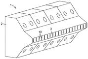
도 1은 예시적인 발포 다이의 전방-측면 사시도.
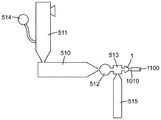
도 2는 발포 다이가 함께 사용될 수 있는 예시적인 압출 장치(extrusion apparatus)의 개략도.
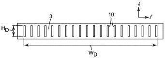
도 3은 예시적인 발포 다이의 예시적인 작업 면(working face)의 정면도.
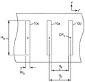
도 4는 도 3의 예시적인 발포 다이의 수개의 다이 오리피스(die orifice)의 확대 정면도.
도 5는 예시적인 발포 다이로부터 생성되는 예시적인 발포 슬래브의 전방-측면 사시도.
도 6은 2개의 행(row)의 오리피스를 보유한, 예시적인 발포 다이의 다른 예시적인 작업 면의 정면도.
도 7은 도그본(dogbone)-형상의 다이 오리피스를 보유한, 예시적인 발포 다이의 다른 예시적인 작업 면의 정면도.
도 8은 제1 세트의 다이 오리피스 및 제2 세트의 다이 오리피스를 보유한, 예시적인 발포 다이의 다른 예시적인 작업 면의 정면도.
도 9는 예시적인 일 세트의 다이 오리피스로부터 방출되는 예시적인 다층 용융된 유동스트림(multilayer molten flowstream)의 정면도.
다양한 도면의 유사한 도면 부호는 유사한 요소를 지시한다. 일부 요소는 동일하거나 동등한 다수로 존재할 수 있으며; 그러한 경우에 단지 하나 이상의 대표적인 요소가 도면 부호에 의해 지정될 수 있지만, 그러한 도면 부호는 모든 그러한 동일한 요소에 적용되는 것이 이해될 것이다. 달리 지시되지 않는 한, 본 명세서의 모든 도면은 축척대로 그려진 것은 아니며, 본 발명의 상이한 실시예를 예시하는 목적을 위해 선택된다. 특히, 다양한 구성요소의 치수는 단지 예시적인 관점에서 도시되며, 다양한 구성요소의 치수들 사이의 관계는 그렇게 지시되지 않는 한 도면으로부터 추론되어서는 안된다.
특성 또는 속성에 대한 수식어로서 본 명세서에 사용되는 바와 같이, 용어 "대체로"는 달리 구체적으로 정의되지 않는 한, 특성 또는 속성이 높은 정도의 근사를 요구함이 없이(예컨대, 정량화할 수 있는 특성에 대해 +/- 20% 이내) 당업자에 의해 용이하게 인식가능할 것임을 의미한다. 각도 배향의 경우, 용어 "대체로"는 시계방향 또는 반시계방향 30도 이내를 의미한다. 용어 "실질적으로"는 달리 구체적으로 정의되지 않는 한, 높은 정도의 근사(예컨대, 정량화할 수 있는 특성에 대해 +/- 10% 이내)를 의미한다. 각도 배향의 경우, 용어 "실질적으로"는 시계방향 또는 반시계방향 10도 이내를 의미한다. 용어 "본질적으로"는 플러스 또는 마이너스 2%(각도 배향의 경우 플러스 또는 마이너스 2도) 이내를 의미하고, 문구 "적어도 본질적으로"는 "정확한" 일치의 특정 경우를 포괄하는 것이 이해될 것이다. 그러나, "정확한" 일치, 또는 예컨대 같은, 균등한, 동일한, 균일한, 일정한 등과 같은 용어를 사용한 임의의 다른 특성화는 절대적인 정밀도 또는 완벽한 일치를 요구하기보다는 특정 환경에 적용가능한 통상의 공차 또는 측정 오차 내에 있는 것으로 이해될 것이다. 당업자는 본 명세서에 사용되는 바와 같이, "본질적으로 없는" 등과 같은 용어가 예컨대 통상적인 세정 절차를 거치는 대규모 생산 장비를 사용할 때 발생할 수 있는 바와 같이, 일부 극히 낮은, 예컨대 0.1% 이하의 양의 재료의 존재를 배제하지 않는 것을 인식할 것이다. 수치 파라미터(치수, 비 등)에 대한 본 명세서에서의 모든 참조는, 특히 변수인 파라미터의 경우에 대해 그러한 파라미터의 다수의 측정치로부터 얻어지는 평균값의 사용에 의해 (달리 언급되지 않는 한) 계산가능한 것으로 이해된다(예컨대, 오리피스의 폭이 오리피스의 장축을 따라 변하는 오리피스의 경우, 오리피스의 폭은 오리피스의 장축을 따른 수개의 위치에서 측정될 수 있고, 평균값이 종횡비(aspect ratio)를 계산하는 목적을 위해 사용될 수 있음).1 is a front-side perspective view of an exemplary foam die.
2 is a schematic diagram of an exemplary extrusion apparatus in which a foam die may be used together;
3 is a front view of an exemplary working face of an exemplary foam die.
Figure 4 is an enlarged front view of several die orifices of the exemplary foam die of Figure 3;
5 is a front-side perspective view of an exemplary foam slab produced from an exemplary foam die.
Figure 6 is a front view of another exemplary working surface of an exemplary foam die having two rows of orifices.
7 is a front view of another exemplary working surface of an exemplary foam die having a dogbone-shaped die orifice.
8 is a front view of another exemplary working surface of an exemplary foam die having a first set of die orifices and a second set of die orifices.
Figure 9 is a front view of an exemplary multilayer molten flowstream that is emitted from an exemplary set of die orifices.
Like reference numbers in the various drawings indicate like elements. Some elements may be present in the same or an equivalent plurality; In such a case, it is to be understood that only one or more representative elements may be designated by reference numerals, but such reference numerals apply to all such identical elements. Unless otherwise indicated, all figures herein are not drawn to scale and are selected for purposes of illustrating different embodiments of the invention. In particular, the dimensions of the various components are shown only in terms of example, and the relationship between the dimensions of the various components should not be deduced from the drawings unless so indicated.
As used herein as a modifier for a characteristic or attribute, the term "generally" means that, unless otherwise specifically defined, without requiring a degree of approximation of the characteristic or property (e.g., +/- 20%) will be readily recognizable by those skilled in the art. For angular orientation, the term "generally" means within 30 degrees in the clockwise or counterclockwise direction. The term "substantially" means a high degree of approximation (e.g., within +/- 10% of the quantifiable characteristic) unless otherwise specifically defined. For angular orientation, the term "substantially" means within 10 degrees in a clockwise or counterclockwise direction. It will be understood that the term "essentially" means within plus or
용어 해설Glossary of terms
발포 다이란 용융된 발포성 유동스트림(molten foamable flowstream)의 압출 시에 존재하는 압력을 견디도록 구성되는 압출 다이를 의미한다. 정의상, 발포 다이는 예컨대 압출기(extruder)로부터 용융된 유동스트림을 수용하도록 구성되는 적어도 하나의 다이 공동(die cavity)을 포함하고, 적어도 하나의 다이 공동과 유체 연통하는 복수의 다이 오리피스를 포함한다.Refers to an extrusion die configured to withstand the pressure present during extrusion of a molten foamable flow stream. By definition, the foam die comprises a plurality of die orifices, including at least one die cavity configured to receive a molten flow stream from an extruder, and in fluid communication with the at least one die cavity.
용융된 발포성 유동스트림이란 용융된 발포성 조성물(molten foamable composition)을 포함하는 용융된 유동스트림을 의미한다. 일부 경우에, 그러한 유동스트림은 예컨대 유동스트림의 단지 하나의 층만이 발포성 조성물을 포함하는 다층 유동스트림일 수 있다.A molten expanded flow stream means a molten flow stream comprising a molten foamable composition. In some cases, such a flow stream may be, for example, a multi-layer flow stream comprising only the foamable composition, but only one layer of the flow stream.
용융된 발포성 조성물이란 발포제(blowing agent)(예컨대, 본 명세서에서 추후에 상세히 논의되는 바와 같이, 기체 또는 액체와 같은 물리적 발포제; 또는 예컨대 상승된 온도에서 화학적으로 분해될 수 있는 화학적 발포제)를 포함하는 용융된 열가소성 유기 중합체 재료를 의미한다.The molten expanded composition refers to a composition comprising a blowing agent (e.g., a physical blowing agent such as a gas or liquid, as discussed in detail herein below) or a chemical blowing agent that can be chemically degraded, for example, at elevated temperatures Means a molten thermoplastic organic polymer material.
비-발포성이란 (예컨대, 용융된 조성물의 고화된(solidified) 생성물이 적어도 본질적으로 1.0과 동일한 상대 밀도를 가진 비-발포(non-foam) 재료이도록) 활성화가능한 발포제가 적어도 본질적으로 없는 용융된 조성물을 의미한다.Non-foamable is a molten composition that is at least essentially free of activatable foaming agents (e.g., such that the solidified product of the molten composition is at least essentially a non-foam material having a relative density equal to 1.0) .
발포체(foam)란 발포 공정이 원하는 정도로 진행된 후에 용융된 발포성 조성물을 고화시킴으로써 얻어지는 유기 중합체 발포체를 의미한다.Foam refers to an organic polymer foam obtained by solidifying a molten foamable composition after the foaming process has progressed to a desired degree.
발포 슬래브란 길이 및 장축, 측방향 폭 및 횡축, 및 두께 및 두께 축을 가진 발포 개체(foam entity)를 의미하며, 3개의 축은 서로 직교하고, 이때 슬래브 폭은 슬래브 두께보다 크다. 정의상, 발포 슬래브는 슬래브의 장축을 따라 적어도 본질적으로 조성적으로 균일하다. 발포 슬래브는 슬래브의 일부분으로서 고밀화된(densified)(예컨대, 비-발포) 재료의 존재를, 고밀화된 재료가 슬래브의 발포 부분과 동일한 작업으로 제조되어 이러한 부분들이 집합적으로 단일체 슬래브(unitary slab)를 형성하는 한, 허용한다.A foamed slab means a foam entity having a length and a major axis, a lateral width and a transverse axis, and a thickness and a thickness axis, the three axes being orthogonal to each other, wherein the slab width is greater than the slab thickness. By definition, the foamed slab is at least essentially coarsely uniform along the long axis of the slab. Foamed slabs are formed by the presence of densified (e.g., non-foamed) material as part of the slab, such that the densified material is manufactured in the same operation as the foamed portion of the slab such that these portions collectively form a unitary slab, As long as it forms a layer.
단일체란 용융된 유동스트림의 합체(coalescence)와 고화에 의해 단일 작업으로 제조되는 그리고 개체를 허용불가하게 손상시키거나 파괴하지 않고서는 부분들로 분리될 수 없는 개체(예컨대, 발포 슬래브)를 의미한다. 단일체 개체는, 개체의 모든 부분(예컨대, 층, 부재 등)이 단일(예컨대 합체/고화) 작업으로 제조되고 서로 결합되어 이러한 부분들이 서로 분리될 수 없고 서로로부터 제거할 수 없는 한, 복합 개체(composite entity)일 수 있다.A monolith refers to an entity (e.g., a foam slab) manufactured in a single operation by coalescence and solidification of a molten flow stream and which can not be separated into parts without unacceptably damaging or destroying the entity . The monolithic entity may be a single entity (e.g., a layer, a member, or the like) that is manufactured and joined together in a single (e.g., coalescing / solidifying) operation so that such portions can not be separated from one another, composite entity.
복합 발포 슬래브(composite foam slab)란 주 발포 상(major foam phase)에 더하여, 고밀화된 재료를 포함하는 적어도 하나의 부 발포 상(minor foam phase)을 포함하는 단일체 발포 슬래브를 의미한다.Composite foam slab refers to a monolithic foam slab that includes at least one minor foam phase that includes a densified material in addition to the major foam phase.
용어 고밀화된은 복합 발포 슬래브의 부 상(minor phase)을 복합 발포 슬래브의 주 발포 상과 구별하기 위해 사용되고, 부 상이 주 발포 상의 그것보다 적어도 약 15% 더 높은 상대 밀도를 나타냄을 의미한다. 용어 "고밀화된"은 설명의 편의를 위해 사용되고, "고밀화된" 재료가 발포체일 수 없음을 의미하지도 않고, 고밀화된 재료가 우선 보다 낮은 밀도로 제조된 다음에 그의 밀도를 증가시키도록 처리된 재료이어야 함을 요구하지도 않는다.The term is used to distinguish the minor phase of the silver-compacted composite foam slab from the main foamed phase of the composite foam slab, meaning that the phase exhibits a relative density at least about 15% higher than that of the main foamed phase. The term "densified" is used for convenience of description, and does not imply that a "densified" material can not be a foam, and a densified material is first prepared at a lower density, Nor is it required to be.
(예컨대 발포 재료의) 상대 밀도는 재료(예컨대, 공기-충전된 셀(air-filled cell)을 포함하는 발포체)의 전체 밀도를 재료의 셀 벽을 형성하는 물질의 밀도로 나눔으로써 얻어지는 무차원 파라미터이다. 상대 밀도는 때때로 환산 밀도(reduced density)로 지칭된다. 예컨대 0.5 g/cc의 밀도를 포함하고 1.35 g/cc의 밀도를 갖는 폴리에스테르로 제조된 셀 벽을 포함하는 폴리에스테르 발포체에 대해, 상대 밀도는 약 0.37이다. 통상적인 비-발포(및 무공성(non-porous)) 재료에 대해, 상대 밀도는 적어도 본질적으로 1.0과 동일할 것이다.The relative density (e.g., of the foam material) is determined by dividing the total density of the material (e.g., the foam comprising the air-filled cell) by the density of the material forming the cell walls of the material, to be. Relative density is sometimes referred to as reduced density. For example, for a polyester foam comprising a cell wall made of a polyester containing a density of 0.5 g / cc and a density of 1.35 g / cc, the relative density is about 0.37. For conventional non-foaming (and non-porous) materials, the relative density will be at least essentially equal to 1.0.
다이 오리피스 기하학적 구조 및 패턴에 관한 다양한 용어(예컨대, 다이 높이, 다이 횡축, 오리피스 높이, 및 측방향으로 인접한, 측방향으로 정렬된, 및 측방향으로 합체된과 같은 용어의 의미)가 다양한 도면을 참조하여 확대되어 본 명세서에 추후에 상세히 정의되고 기술된다.Various terms relating to the die orifice geometry and pattern (e.g., die height, die transverse axis, orifice height, and the meaning of terms such as laterally adjacent, laterally aligned, and laterally incorporated) And are defined and described in detail later in this specification.
발포 다이Foam die
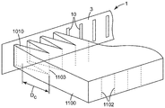
도 1의 예시적인 실시예에 도시된 바와 같은 발포 다이(1)가 본 명세서에 개시된다. 발포 다이(1)는 도 2의 예시적인 실시예에 도시되고 본 명세서에서 추후에 상세히 논의되는 바와 같이, 임의의 적합한 압출 장치와 함께 사용될 수 있다. 발포 다이(1)는 작업 면(3)을 포함하는 주 본체(2)를 포함한다. 도 3의 정면도에 도시된 바와 같이, 작업 면(3)은 복수의 다이 오리피스(10)를 포함한다.A foam die 1 as shown in the exemplary embodiment of FIG. 1 is disclosed herein. The
도 3에 도시된 예시적인 배열에 관하여, 다이 오리피스(10)는 다이(1)의 횡축(l)을 따라 이격되어 다이 폭(WD)을 확립한다. 다이 폭(WD)은 다이의 횡축을 따른, 다이 오리피스의 가장 멀리 떨어진 에지들 사이의 거리로 정의된다. 다이 오리피스(10)는 또한 다이 오리피스의 가장 멀리 떨어진 위치들 사이의(즉, 도 3의 예시적인 실시예에 도시된 바와 같이, 다이 오리피스의 "최상부" 및 "최하부" 에지들 사이의), 다이의 높이 축(h)을 따른 거리로 정의되는 다이 높이(HD)를 확립한다. 정의상 다이(1)의 높이 축(h)은 다이(1)의 횡축(l)에 직교한다(높이 축(h) 및 횡축(l) 둘 모두가 다이 오리피스의 압출물 유출의 방향에 직교하며, 이러한 방향은 도 3 및 도 4에서 평면외(out-of-plane)임). 예컨대 용어 높이 축 및 다이 높이에 사용되는 바와 같은 용어 높이, 높이 축을 따른 방향을 나타내기 위해 사용되는 바와 같은 용어 수직, 및 예컨대 높이 축을 따른 위치를 나타내기 위해 사용되는 바와 같은 상부/최상부 및 하부/최하부와 같은 용어는 전적으로 본 명세서에 제시된 예시적인 도면에 관한 설명의 편의를 위해 사용되고, 지면(Earth)에 대한 임의의 특정 배향을 필요로 하지 않는다. (추후의 논의에서, 발포 다이(1)의 "높이" 축(h)이 발포 다이(1)의 사용에 의해 제조되는 발포 슬래브의 "두께" 축(t)에 대응하는 것이 명백할 것이다.)3, the die
정의상, 다이 폭(WD)(다이의 횡축을 따름, 이러한 축을 따라 다이 오리피스가 이격됨)이 다이 높이(HD)보다 크다. 다양한 실시예에서, 다이 폭 대 다이 높이의 비는 적어도 약 1.1, 1.2, 1.5, 2.0, 4:1, 8:1, 또는 12:1일 수 있다. 추가의 실시예에서, 다이 폭 대 다이 높이의 비는 최대 약 50:1, 30:1, 또는 20:1일 수 있다. 다양한 실시예에서, 다이(1)는 적어도 약 4.0, 8.0, 12, 16, 20, 30, 또는 40 mm의 다이 높이를 나타낼 수 있다. 추가의 실시예에서, 다이(1)는 최대 약 80, 40, 30, 25, 또는 20 mm의 다이 높이를 나타낼 수 있다. 다양한 실시예에서, 다이(1)는 적어도 약 2.0, 4.0, 8.0, 10, 20, 40, 100 cm, 또는 적어도 약 0.5, 1.0, 또는 2 미터의 다이 폭을 나타낼 수 있다. 추가의 실시예에서, 다이(1)는 최대 약 3, 2, 1, 또는 0.5 미터, 또는 100, 80, 60, 50, 40, 30, 25, 또는 20 cm의 다이 폭을 나타낼 수 있다.By definition, the die width W D (along the axis of the die, along which the die orifice is spaced) is greater than the die height H D. In various embodiments, the ratio of die width to die height may be at least about 1.1, 1.2, 1.5, 2.0, 4: 1, 8: 1, or 12: 1. In a further embodiment, the ratio of die width to die height may be up to about 50: 1, 30: 1, or 20: 1. In various embodiments, the die 1 may exhibit a die height of at least about 4.0, 8.0, 12, 16, 20, 30, or 40 mm. In a further embodiment, the die 1 may exhibit a die height of up to about 80, 40, 30, 25, or 20 mm. In various embodiments, die 1 may exhibit a die width of at least about 2.0, 4.0, 8.0, 10, 20, 40, 100 cm, or at least about 0.5, 1.0, or 2 meters. In a further embodiment, the die 1 may exhibit a die width of up to about 3, 2, 1, or 0.5 meters, or 100, 80, 60, 50, 40, 30, 25, or 20 cm.
다이 오리피스는 본 명세서에서 논의되는 측방향 정렬의 조건이 충족되는 한, 도 4에 예시적인 오리피스 패턴에 대해 도시된 바와 같이, 임의의 원하는 중심간 간격(center-to-center spacing)(dc)으로 존재할 수 있다. 다양한 실시예에서, 중심간 간격(dc)은 예컨대 최대 약 25, 20, 15, 10, 8, 6, 4, 2, 또는 1 mm일 수 있다. 추가의 실시예에서, 중심간 간격은 적어도 약 0.5, 1, 1.5, 2, 2.5, 4, 6, 8, 10, 또는 15 mm일 수 있다. 중심간 간격은 반드시 다양한 오리피스들 사이에서 일정하도록 요구되지는 않으며; 따라서, 중심간 간격은 평균일 수 있다. 다양한 실시예에서, 다이 오리피스의 총 개수는 적어도 약 10, 20, 30, 40, 80, 100, 200, 400, 또는 800개일 수 있다. 추가의 실시예에서, 다이 오리피스의 총 개수는 최대 약 5000, 2000, 1200, 1000, 600, 400, 또는 200개일 수 있다.The die orifices may have any desired center-to-center spacing (d c ), as shown for the exemplary orifice pattern in FIG. 4, so long as the conditions of the lateral alignment discussed herein are met. Lt; / RTI > In various embodiments, the center-to-center spacing d c may be, for example, up to about 25, 20, 15, 10, 8, 6, 4, 2, or 1 mm. In further embodiments, the center-to-center spacing may be at least about 0.5, 1, 1.5, 2, 2.5, 4, 6, 8, 10, or 15 mm. The center-to-center spacing is not necessarily required to be constant among the various orifices; Thus, the center-to-center spacing can be an average. In various embodiments, the total number of die orifices may be at least about 10, 20, 30, 40, 80, 100, 200, 400, or 800. In a further embodiment, the total number of die orifices may be up to about 5000, 2000, 1200, 1000, 600, 400, or 200.
정의상, 다이 오리피스(10)는 다이(1)의 높이 축(h)과 적어도 실질적으로 정렬되는 그리고 다이(1)의 횡축(l)에 적어도 실질적으로 직교하는 장축을 가진 기다란 형상을 나타낸다. 여기서 그리고 다른 곳에서, 용어 실질적으로 정렬된은 각도 정렬에 관해 사용되는 바와 같이, 정확하게 정렬된 상태의 플러스 또는 마이너스 15도 이내에 있음을 의미한다. 유사하게, 용어 실질적으로 직교하는은 정확하게 직교하는 상태의 플러스 또는 마이너스 15도 이내에 있음을 의미한다. 다양한 실시예에서, 다이 오리피스는 다이(1)의 높이 축(h)의 플러스 또는 마이너스 10도, 또는 플러스 또는 마이너스 5도 이내에 정렬되는 장축을 나타낼 수 있다. 일부 실시예에서(예컨대, 도 3 및 도 4에 도시된 바와 같이), 다이 오리피스의 장축은 다이(1)의 높이 축(h)과 적어도 본질적으로 정렬되고 다이(1)의 횡축(l)에 적어도 본질적으로 직교할 수 있다. 그러나, 이는 엄격히 요구되지는 않는다. 또한, 모든 다이 오리피스가 반드시 다이의 높이 축(h)에 대한 정확한 동일한 형상, 높이, 폭, 종횡비, 각도 배향 등을 공유할 필요는 없다. 그러나, 일부 실시예에서(예컨대, 도 3에 도시된 바와 같이), 적어도 일부 오리피스가 적어도 본질적으로 동일한 높이 및/또는 형상을 공유할 수 있고/있거나, 다이의 횡축을 따라 적어도 본질적으로 균일하게 이격될 수 있고/있거나, 적어도 본질적으로 동일한 각도 배향을 공유할 수 있다.By definition, the
도 4를 참조하면, 다양한 실시예에서, 다이 오리피스는 적어도 약 0.2, 0.4, 0.5, 0.6, 0.8, 1.0, 1.5, 또는 2.0 mm의 오리피스 폭(Wo)을 나타낼 수 있다. 추가의 실시예에서, 다이 오리피스는 최대 약 4, 3, 2, 1.5, 1.0, 0.8, 0.7, 또는 0.6 mm의 오리피스 폭(Wo)을 나타낼 수 있다. 다양한 실시예에서, 다이 오리피스는 적어도 약 4, 8, 12, 16 또는 20 mm의 오리피스 높이(Ho)(도 4에 도시된 바와 같이, 다이의 장축을 따라 측정되는 단부간 거리(end-to-end distance)를 의미함)를 나타낼 수 있다. 추가의 실시예에서, 다이 오리피스는 최대 약 100, 80, 40, 30, 25, 또는 20 mm의 오리피스 높이(Ho)를 나타낼 수 있다. (예컨대, 도 3에 도시된 일반 유형의) 일부 실시예에서, 모든 오리피스의 오리피스 높이는 동일할 수 있고, 다이 높이와 동일할 수 있다. 그러나, 이는 엄격히 필요하지는 않다.4, in various embodiments, the die orifice may exhibit an orifice width (W o ) of at least about 0.2, 0.4, 0.5, 0.6, 0.8, 1.0, 1.5, or 2.0 mm. In a further embodiment, the die orifice may exhibit an orifice width (W o ) of up to about 4, 3, 2, 1.5, 1.0, 0.8, 0.7, or 0.6 mm. In various embodiments, the die orifice may have an orifice height H o of at least about 4, 8, 12, 16, or 20 mm (as shown in FIG. 4, end-to- -end distance "). In a further embodiment, the die orifice may exhibit an orifice height (H o ) of up to about 100, 80, 40, 30, 25, or 20 mm. In some embodiments (e.g., of the general type shown in Figure 3), the orifice height of all orifices may be the same and may be the same as the die height. However, this is not strictly necessary.
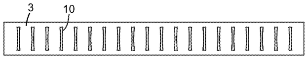
다양한 실시예에서, 다이 오리피스는 적어도 약 4:1, 6:1, 8:1, 10:1, 또는 12:1의 오리피스 높이(Ho) 대 오리피스 폭(Wo)의 종횡비를 나타낼 수 있다. 오리피스 폭(Wo)은 다이의 횡축과 적어도 실질적으로 정렬되는 방향을 따라 측정되고; 폭이 오리피스의 높이(즉, 장축)를 따라 변하면, 오리피스 폭의 평균값이 종횡비를 계산하는 데 사용될 수 있다. 인식가능한 장축, 높이 및 폭이 당업자에 의해 식별될 수 있는 한, 다이 오리피스가 기다란 형상과 장축을 나타내고 그것이 높이/폭 종횡비를 나타낸다는 요건이 오리피스가 엄격히 선형이어야 함(또는 그것이 에컨대 엄격히 곧은 벽을 가져야 함)을 필요로 하지는 않는 것이 강조된다. 즉, 필요할 경우, 다이 오리피스가 예컨대 타원형, 아치형(예컨대, 바나나-형상) 등일 수 있다. 일부 실시예에서, 적어도 일부 오리피스가 대체로 "도그본" 형상을 포함할 수 있다. 이는 오리피스의 제1 종단 단부(예컨대, 상부 단부)에 근접한 위치에서의 오리피스의 폭(Wo)과 오리피스의 제2 종단 단부(예컨대, 하부 단부)에 근접한 위치에서의 오리피스의 폭이 각각 오리피스의 장축을 따라(그리고 그에 따라 다이의 높이 축(h)을 따라) 중심에 위치되는 오리피스의 섹션에서의 오리피스의 폭보다 큰 형상을 나타낸다. 예시적인 도그본-형상의 다이 오리피스가 도 7에 도시된다. 다양한 실시예에서, 오리피스의 단부-근접 위치에서의 오리피스 폭 대 중심 위치에서의 오리피스의 폭의 비는 적어도 약 1.2, 1.4, 1.6, 1.8, 2.0, 2.5, 또는 3.0 내지 1.0일 수 있다.In various embodiments, the die orifice may exhibit an aspect ratio of the orifice height (H o ) to the orifice width (W o ) of at least about 4: 1, 6: 1, 8: 1, 10: 1, . The orifice width W o is measured along a direction at least substantially aligned with the transverse axis of the die; As the width varies along the height of the orifice (i.e., the major axis), the average value of the orifice width can be used to calculate the aspect ratio. As long as recognizable long axes, heights and widths can be discerned by those skilled in the art, the requirement that the die orifices exhibit elongated shapes and long axes and that they exhibit height / width aspect ratios requires that the orifices be strictly linear (or, ) In order to achieve the desired result. That is, if necessary, the die orifices may be, for example, elliptical, arcuate (e.g., banana-shaped) or the like. In some embodiments, at least some of the orifices may include a generally "dog bone" shape. This is because the width W o of the orifice at a location near the first end of the orifice (e.g., the top end) and the width of the orifice at a location near the second end (e.g., the bottom end) Which is greater than the width of the orifice in the section of the orifice centered along the major axis (and hence along the height axis h of the die). An exemplary dog bone-shaped die orifice is shown in Fig. In various embodiments, the ratio of the orifice width at the end-proximal position to the proximal position of the orifice may be at least about 1.2, 1.4, 1.6, 1.8, 2.0, 2.5, or 3.0 to 1.0.
다이 오리피스의 측방향으로 정렬된 패턴A pattern aligned laterally of the die orifice
다이 오리피스(10)는 그들이 측방향으로 정렬된 패턴으로 있도록 다이(10)의 횡축을 따라 이격된다. 그러한 배열의 이점은 예시적인 단일체 발포 슬래브(1100)가 다이(1)의 오리피스(10)로부터 방출되는 용융된 발포성 압출물 유동스트림(1010)의 합체와 고화에 의해 생성되고 있는 것을 도시한 도 5의 (이상화된) 표현의 검토에 의해 인식될 수 있다. 당업자는 발포 다이의 횡축을 따라 측방향으로 정렬된 패턴으로 이격되는 복수의 다이 오리피스 - 이러한 오리피스는 적어도 실질적으로 다이의 높이 축을 따라 배향되는 장축을 가짐 - 로부터의 용융된 발포성 압출물 유동스트림(1010)의 방출이, 발포 슬래브(1100)가 주로 용융된 발포성 압출물 유동스트림의 측방향 합체에 의해 형성되는 결과를 가져오는 것을 인식할 것이다. 즉, 발포 슬래브(1100)는 주로 용융된 유동스트림 팽창(대부분 스트림이 다이 오리피스로부터 배출될 때 개시되는 발포로 인함)에 의해 그리고 측방향으로(도 5의 도면에서 우측 및 좌측으로) 확산되어 서로 합류하고 합체됨으로써 형성된다.The die orifices 10 are spaced along the transverse axis of the die 10 such that they are in a laterally aligned pattern. The advantage of such an arrangement is that the exemplary
그러한 오리피스 배열과 그의 사용, 및 생성되는 발포 슬래브 제품은 발포 슬래브가 용융된 발포성 압출물 유동스트림을 (예컨대, 통상적인 "코트행어(coathanger)" 스타일 다이/오리피스에서와 같이) 다이의 횡축을 따라 배향되는 장축을 갖는 적은 수의 슬롯 오리피스(slot orifice)(예컨대, 하나의 오리피스)를 통해 방출함으로써 생성되는 배열과 구별될 것이다. 당업자는 그러한 "코트행어" 스타일 다이/오리피스 설계의 사용에서 측방향 합체가 거의 또는 전혀 발생하지 않을 수 있는 것을 인식할 것이다.Such an orifice arrangement and its use, and the resulting foam slab product, can be used to produce a foamed extrudate flow stream in which the foam slabs are melted along a transverse axis of the die (e.g., as in a conventional "coathanger" style die / orifice) Will be distinguished from arrays produced by discharging through a small number of slot orifices (e.g., one orifice) having a long axis of orientation. Those skilled in the art will recognize that in the use of such "coat hanger" style die / orifice designs little or no lateral merging can occur.
본 명세서에 개시된 배열은 또한 예컨대 발포 슬래브가 용융된 발포성 압출물 유동스트림을 측방향으로 정렬되지 않는 (예컨대 많은 수의 오리피스를 예컨대 다수의 행 및 열의 어레이로 포함하는 천공된 금속 "다이 플레이트(die plate)"의) 다수의 다이 오리피스를 통해 방출함으로써 생성되는 배열과 구별될 수 있다. 당업자는 그러한 설계가 용융된 유동스트림이 주로 다이의 횡축을 따른 방향으로 합체되기보다는, 예컨대 적어도 대체로 다이의 높이 축을 따른 방향으로 상당한 정도로 병합되고 합체되게 할 수 있는 것을 인식할 것이다. 본 명세서에 개시된 바와 같은 측방향으로 정렬된 다이 오리피스를 수반하지 않는 하나의 그러한 통상적인 다이 플레이트 배열이 예컨대 윌리(Wiley)의 미국 특허 제3573152호에 기술된다. 당업자는 본 명세서의 개시 내용에 기초하여, 본 명세서에 개시된 바와 같은 측방향으로 정렬된 오리피스 배열이 예컨대 발포 슬래브 제품의 증가된 균일성, 발포 슬래브가 그의 장축을 따라 구부러질 때의 증가된 굽힘 강성(bending stiffness) 및/또는 탈층에 대한 저항성(resistance to delamination) 등을 포함하는 여러 가지 이점을 제공할 수 있는 것을 인식할 것이다.The arrangement disclosed herein may also be used to form a foamed extrudate flow stream in which, for example, a foamed extrudate flow stream that is not laterally aligned (e.g., a perforated metal "die ") comprising a large number of orifices in an array of, plate ") < / RTI > through a plurality of die orifices. Those skilled in the art will recognize that such a design can allow the molten flow streams to be merged and coalesced to a substantial degree, e.g., at least approximately in the direction along the height axis of the die, rather than being incorporated in the direction along the major axis of the die. One such conventional die plate arrangement that does not involve a laterally aligned die orifice as disclosed herein is described, for example, in U.S. Patent No. 3,573,152 to Wiley. Those skilled in the art will appreciate that the laterally aligned orifice arrangements as disclosed herein can be used for various purposes, for example, increased uniformity of the foam slab product, increased bending stiffness when the foam slab is bent along its major axis and may provide several advantages including bending stiffness and / or resistance to delamination.
다이(1)를 사용하여 발포 슬래브(1100)를 제조하는 방법은 도 5에 이상화된 예시적인 방식으로 예시되는 합체 거리(coalescence distance)(Dc)에 의해 특징지어질 수 있다. 합체 거리(Dc)는 측방향으로 이웃한 용융된 유동스트림(1010)이 (예컨대 위치(1103)에서) 서로 접촉하여 병합되고 합체되어 발포 슬래브(1100)를 형성하는, 용융된 유동스트림의 유동의 방향을 따른, 다이 오리피스(10)로부터의 (평균한) 거리이다. 합체 거리(Dc)는 물론 다이 오리피스의 측방향 간격에 의해 영향을 받을 수 있다. 그러나, (예컨대 주어진 오리피스 간격에 대해) 합체 거리(Dc)는 예컨대 압출된 재료의 처리율(throughput rate)에 의해 그리고 또한 예컨대 테이크어웨이 속도(takeaway speed)(예컨대 발포 슬래브가 이동 벨트 상에 또는 이동 벨트들 사이에 수집되는 경우)에 의해 조절될 수 있다. 합체 거리(Dc)는 이들 장치 구성 및/또는 작동 조건 중 임의의 것 또는 모두에 의해 임의의 원하는 값으로 조절될 수 있다. 일부 상황 하에서, 예컨대 유동스트림의 표면이 여전히 그 사이의 우수한 접합(예컨대 용융-접합)을 촉진시키기에 충분히 고온일 때 용융된 유동스트림을 서로 접촉시키기 위해, 발포 슬래브 내에 중공 채널이 존재하지 않는 것을 보장하기 위해(아래에서 논의되는 바와 같음), 기타 등등을 위해, 합체 거리(Dc)를 최소화시키는 것이 유리할 수 있다. 다양한 실시예에서, 합체 거리(Dc)는 약 50, 40, 30, 10, 4, 2, 또는 1 mm 미만일 수 있다.The method of making the
도 5를 추가로 참조하면, 인접한 유동스트림(1010)이 서로 접촉하는 합류점(meeting-point)(1103)이 최종 발포 슬래브 내에 식별가능한 계면 경계(1102)를 생성할 수 있다. 그러나, 예컨대 발포 공정에서 발생할 수 있는 측방향 확산으로 인해, 일부 실시예에서 그러한 계면 경계(1102)가 인접한 유동스트림(1010)이 그로부터 생성되는 다이 오리피스(10)의 간격보다 (발포 슬래브의 측방향 폭에 걸쳐) 더욱 이격될 수 있다.5, a meeting-
작동예에 기초하여, 본 명세서의 개시 내용이 형성된 슬래브의 장축을 따라 연장되는 내부 거시적 중공(예컨대, 공기-충전된) 기다란 채널을 거의 또는 전혀 나타내지 않는 단일체 발포 슬래브의 생성을 가능하게 하는 것이 인식될 것이다. (일부 상황에서, 그러한 채널은 유동스트림의 고화가 발생하기 전에 용융된 발포성 압출물 유동스트림의 적어도 일부의 표면이 다른 유동스트림의 표면과 완전히 접촉하지 못함으로 인해, 의도하지 않게 또는 설계에 의해 형성될 수도 있다.) 그러한 채널을 거의 또는 전혀 나타내지 않는 단일체 발포 슬래브는 채널형성되지 않은(non-channeled) 발포 슬래브로 지칭될 것이다. (슬래브의 장축을 따라 연장되는 내부 거시적 중공 기다란 채널이 발포체의 실제 셀과 혼동되지 않아야 하며; 또한, 발포 슬래브의 주 표면 또는 작은 에지를 따른 약간의 불규칙한 부분은 내부 채널로 고려되지 않는다.) 채널형성되지 않은 슬래브는, 슬래브의 장축(압출 방향)에 직교하는 평면을 따른 단면으로 커팅되는 경우에 그러한 내부 거시적 중공 기다란 채널을 본질적으로 전혀(즉, 노출된 표면 단면의 총 면적의 백분율로서 측정시 평균 1% 미만) 나타내지 않을 슬래브이다. 따라서, 적어도 일부 실시예에서, 본 명세서에 개시된 바와 같은 단일체 발포 슬래브(이는 복합 슬래브일 수 있음)는 채널형성되지 않은 단일체 발포 슬래브이다.Based on the example of operation, it is recognized that enabling the creation of monolithic foamed slabs with little or no internal macroscopic hollow (e.g., air-filled) elongated channels extending along the long axis of the formed slab Will be. (In some circumstances, such channels may be formed by unintentionally or by design due to the fact that the surface of at least a portion of the molten expanded extrudate flow stream does not fully contact the surface of the other flow stream before the solidification of the flow stream occurs Monolithic foam slabs that exhibit little or no such channels will be referred to as non-channeled foam slabs. (The inner macroscopically hollow elongated channel extending along the longitudinal axis of the slab should not be confused with the actual cell of the foam, and also some irregular portions along the major surface or small edge of the foam slab are not considered as inner channels) The non-formed slabs are such that when cut into a cross-section along a plane perpendicular to the long axis (extrusion direction) of the slab, such inner macroscopically hollow channels are essentially not at all (i.e., as a percentage of the total area of the exposed cross- Less than 1% on average). Thus, in at least some embodiments, a monolithic foam slab as disclosed herein (which may be a composite slab) is a monolithic foam slab that is not channeled.
필요할 경우 채널형성되지 않은 발포 슬래브를 생성하는 능력은 기다란 다이 오리피스(예컨대, 슬롯)를 통한 용융된 발포성 유동스트림의 압출이, 방출되는 용융된 압출물 유동스트림이 그것이 발포될 때 구김(crumpling) 또는 파형(waviness)을 나타내는 "주름(corrugation)"으로 불리는 현상을 초래하는 것으로 당업자에게 알려져 있음을 고려할 때 놀라운 것이다. 이러한 현상은 통상적으로는 용융된 압출물 유동스트림이 오리피스의 장축을 따른 방향으로 팽창될 수 없도록 적어도 어느 정도 제한되어(이는 그러한 방향으로 유동스트림과 이웃하는 용융된 재료에 의해 유동스트림이 그렇게 하는 것이 방지되기 때문임), 용융된 스트림이 이러한 축을 따라 "주름형성"되게 하는 것에 기인하는 것으로 여겨진다. 본 작동에서, 채널형성되지 않은 발포 슬래브가 신뢰성 있게 생성되었으며, 이는 기다란 다이 오리피스를 본 명세서에 기술된 바와 같이 서로 측방향으로 인접하게 위치시키는 것이 그럼에도 불구하고 발생할 수 있는 임의의 그러한 주름형성이 용융된 유동스트림이 병합되고 합체되어 채널형성되지 않은 발포 슬래브를 생성하는 것을 방해하지 않는 것을 제공할 수 있음을 나타낸다.The ability to produce a non-channeled foam slab, if desired, is achieved by the extrusion of the molten expanded flow stream through a long die orifice (e.g., a slot), the molten extrudate flow stream from which it is crumpled, Which is known to those skilled in the art to result in a phenomenon called "corrugation " that represents waviness. This phenomenon is usually limited at least to some extent so that the molten extrudate flow stream can not expand in the direction along the long axis of the orifice (which is because the flow stream does so by the molten material that is adjacent to the flow stream in that direction , Which is believed to be due to the molten stream being "corrugated" along this axis. In this operation, a non-channeled foam slab has been reliably produced, which means that the long die orifices are positioned laterally adjacent one another as described herein, and that any such creasing that may occur nevertheless nevertheless melt Lt; RTI ID = 0.0 > non-channeled < / RTI > foamed slabs.
도 5를 참조하면, 본 명세서에 개시된 배열이 다이 오리피스 패턴의 다양한 기하학적 파라미터와 그로부터 용융된 발포성 유동스트림을 방출함으로써 형성되는 발포 슬래브의 기하학적 파라미터 사이의 소정 관계를 제공할 수 있는 것이 인식될 것이다. 다양한 실시예에서, 발포 슬래브의 슬래브 두께는 적어도 약 2% 내지 최대 약 5, 10, 15, 20, 30, 50, 100, 또는 200%의 비율만큼 적어도 (평균하여) 다이 높이보다 클 수 있으며, 이때 백분율은 다이 높이에 기초한다. (편의상, 용어 "두께"가 발포 슬래브의 최단 치수를 나타내도록 선택되었고, 한편 용어 "높이"가 발포 슬래브를 생성하기 위해 사용되는 다이 및 다이 오리피스의 대응하는 치수에 더욱 적합한 것으로 간주되었다. 이들 모두는 도 5에 도시된 바와 같은 상/하 방향에 대응한다.) 특정 실시예에서, 다이 오리피스(10)는 다이 오리피스의 높이가 (예컨대, 도 1 및 도 3 내지 도 5의 예시적인 실시예에서와 같이) 다이 높이를 한정하는 단일 행(single row)으로 배열될 수 있다. 다양한 실시예에서, 발포체의 슬래브 두께는 적어도 약 2% 내지 최대 약 5, 10, 15, 20, 또는 30%의 비율만큼 오리피스 높이보다 클 수 있으며, 이때 백분율은 오리피스 높이에 기초한다.5, it will be appreciated that the arrangement disclosed herein can provide a predetermined relationship between the various geometric parameters of the die orifice pattern and the geometrical parameters of the foam slabs formed thereby by discharging the molten expanded flow stream. In various embodiments, the slab thickness of the foamed slab may be at least (on average) greater than the die height by a ratio of at least about 2% up to about 5, 10, 15, 20, 30, 50, 100, or 200% Where the percentage is based on the die height. (For convenience, the term "thickness" was chosen to represent the shortest dimension of the foam slab, while the term "height" was considered to be more suited to the corresponding dimensions of the die and die orifices used to create the foam slab. In a particular embodiment, the
다양한 실시예에서, 발포 슬래브의 슬래브 폭은 적어도 (평균하여) 다이 폭의 약 플러스 2% 내지 약 플러스 5, 10, 15, 20, 30, 50, 또는 100%일 수 있다. 다양한 실시예에서, 발포 슬래브의 폭은 발포 슬래브의 슬래브 두께의 적어도 약 1.1, 1.2, 1.5, 2, 4, 6, 8, 또는 10배일 수 있다. 추가의 실시예에서, 슬래브 폭은 슬래브 두께의 최대 약 400, 200, 100, 80, 60, 40, 20, 또는 10배일 수 있다. 다양한 실시예에서, 슬래브 폭은 적어도 약 2.0, 4.0, 8.0, 10, 20, 30, 또는 40 cm일 수 있다. 추가의 실시예에서, 발포 슬래브의 슬래브 폭은 최대 약 3, 2, 1, 또는 0.5 미터, 또는 적어도 약 100, 80, 60, 50, 40, 30, 25, 또는 20 cm일 수 있다. 다양한 실시예에서, 발포 슬래브의 슬래브 두께는 적어도 약 4, 8, 12, 16, 20, 30, 또는 40 mm일 수 있다. 추가의 실시예에서, 발포 슬래브의 슬래브 두께는 최대 약 200, 160, 80, 40, 30, 25, 또는 20 mm일 수 있다. (모든 그러한 값과 범위는 생성된 상태 그대로의, 즉 발포 슬래브의 임의의 커팅 또는 트리밍(trimming) 전의 발포 슬래브에 대한 것이다.) 위의 논의가 주로 그렇게 형성된 발포 슬래브가 다이 높이보다 적어도 약간 더 두껍고 그리고/또는 다이의 측방향 폭보다 적어도 약간 더 넓은 경우에 중점을 두었지만, 이는 반드시 그렇게 요구되지는 않는다. 실제로, 발포성 조성물의 특정 특성과 조성물을 처리하는 방식에 따라, 그렇게 형성된 발포 슬래브가 예컨대 두께 및/또는 폭에 있어서 다이 높이 및/또는 다이 폭과 유사하거나 심지어 그보다 약간 더 작을 수 있다(작동예 3에 의해 증명되는 바와 같음).In various embodiments, the slab width of the foamed slab may be at least (on average) about 2% to about 5, 10, 15, 20, 30, 50, or 100% of the die width. In various embodiments, the width of the foam slab may be at least about 1.1, 1.2, 1.5, 2, 4, 6, 8, or 10 times the slab thickness of the foam slab. In a further embodiment, the slab width may be up to about 400, 200, 100, 80, 60, 40, 20, or 10 times the slab thickness. In various embodiments, the slab width may be at least about 2.0, 4.0, 8.0, 10, 20, 30, or 40 cm. In a further embodiment, the slab width of the foamed slab may be up to about 3, 2, 1, or 0.5 meters, or at least about 100, 80, 60, 50, 40, 30, 25, or 20 cm. In various embodiments, the slab thickness of the foamed slab may be at least about 4, 8, 12, 16, 20, 30, or 40 mm. In a further embodiment, the slab thickness of the foamed slabs can be up to about 200, 160, 80, 40, 30, 25, or 20 mm. (All such values and ranges are for the foamed slab as it is produced, i.e., before any cutting or trimming of the foamed slab.) The above discussion is based primarily on the fact that the foamed slab thus formed is at least slightly thicker than the die height And / or at least slightly wider than the lateral width of the die, but this is not necessarily so. Indeed, depending on the particular characteristics of the foamable composition and the manner in which the composition is to be treated, the foam slab thus formed may be similar to, or even slightly smaller than, the die height and / or die width in thickness and / or width Lt; / RTI >
측방향 정렬 및 측방향 인접성의 결정Determination of lateral alignment and lateral adjacency
측방향으로 정렬된 오리피스 패턴이란 다이의 작업 면의 총 오리피스 면적의 적어도 약 80%가 각각 적어도 하나의 다른 오리피스에 측방향으로 인접한 오리피스에 의해 집합적으로 제공됨을 의미한다. 주어진 다이 오리피스가 적어도 하나의 다른 오리피스에 측방향으로 인접하는지 여부는 기하학적 검사에 의해 결정될 수 있다. 구체적으로, 주어진 다이 오리피스(예컨대 도 4의 오리피스(10a))가 어떤 다른 다이 오리피스(예컨대 도 4의 오리피스(10b))에 측방향으로 인접한 것은 주어진 오리피스의 (다이의 높이 축을 따른) 높이의 적어도 80%를 따른 위치가 어떤 다른 오리피스에 측방향으로 인접하여야 함을 의미한다. 주어진 오리피스의 수직 높이를 따른 임의의 특정 위치가 어떤 다른 오리피스에 측방향으로 인접하기 위해서는, 그러한 위치로부터(구체적으로, 그러한 위치에 있는 오리피스의 가까운 에지로부터) 다이의 횡축과 정렬되는 방향을 따라 연장되는 선이 약 25 mm의 거리 내에서 어떤 다른 오리피스의 가까운 에지와 만나야 한다. (이러한 범위 내에 있는 2개의 오리피스들 사이의 에지간 거리(edge-to-edge distance)(de)가 많은 압출/발포 조건 하에서, 2개의 오리피스로부터의 압출물의 만족스러운 합류와 합체를 허용할 수 있는 것으로 여겨진다. 그러나, 당업자는 (예컨대 처리량, 밀도, 점도, 결정화율 등과 같은) 재료 파라미터 및/또는 작동 파라미터가 임의의 특정 상황에서, 만족스러운 합류와 합체를 허용하는 거리(de)에 어느 정도 영향을 미칠 수 있는 것을 인식할 것이다.)The laterally aligned orifice pattern means that at least about 80% of the total orifice area of the working surface of the die is collectively provided by laterally adjacent orifices to at least one other orifice, respectively. Whether or not a given die orifice is laterally adjacent to at least one other orifice can be determined by a geometric check. Specifically, it is contemplated that a given die orifice (e.g.,
따라서, 도 4의 예시적인 도면에서, 오리피스(10a)의 수직 중심점은 에지간 거리(de)가 약 25 mm 이하인 한 이웃한 오리피스(10b)에 측방향으로 인접한다. 실제로, 도 4의 설계에서, 오리피스(10a)의 수직 높이의 적어도 본질적으로 100%를 따른 위치가 오리피스(10b)에 측방향으로 인접한다. 동일한 고려 사항이 이웃한 오리피스(10c)에 적용된다. 따라서, 약 25 mm 이하의 에지간 거리를 고려할 때, 도 3 및 도 4의 다이 오리피스의 배열이 다이 오리피스의 예시적인 측방향으로 정렬된 패턴을 나타낸다. 다양한 실시예에서, 이웃한 다이 오리피스들 사이의 에지간 거리는 평균하여 약 20, 15, 10, 5, 2, 또는 1 mm 미만일 수 있다. 다양한 실시예에서, 이웃한 다이 오리피스들 사이의 에지간 거리는 평균하여 적어도 약 0.1, 0.2, 0.5, 1, 2, 또는 4 mm일 수 있다.4, the vertical center points of the
일부 실시예에서, 다이의 작업 면의 총 오리피스 면적의 적어도 약 85, 90, 또는 100%가 각각 적어도 하나의 다른 오리피스에 측방향으로 인접한 오리피스에 의해 집합적으로 제공될 것이다. 일부 실시예에서, 다이의 작업 면의 총 오리피스 면적의 적어도 약 80, 90, 또는 95%가 각각 적어도 2개의 다른 오리피스에 측방향으로 인접한 오리피스에 의해 집합적으로 제공될 것이다. 특정 실시예에서, 작업 면의 측방향 최외부 오리피스를 제외한 모든 오리피스가 각각 적어도 2개의 다른 오리피스에 측방향으로 인접할 것이다(도 3의 예시적인 설계에서와 같음, 역시 약 25 mm 이하의 에지간 거리(de)를 가정함).In some embodiments, at least about 85, 90, or 100% of the total orifice area of the working surface of the die will be collectively provided by laterally adjacent orifices, respectively, to at least one other orifice. In some embodiments, at least about 80, 90, or 95% of the total orifice area of the working surface of the die will be collectively provided by laterally adjacent orifices, respectively, to at least two other orifices. In a particular embodiment, all of the orifices except the lateral outermost orifices of the working surface will be laterally adjacent to at least two different orifices (as in the exemplary design of Fig. 3, also with an edge-to-edge distance (d e )).
추가의 실시예에서, 적어도 일부 다이 오리피스는 다른 다이 오리피스에 밀접하게 측방향으로 인접할 수 있으며, 이는 전술된 바와 같은 에지간 거리가 약 6 mm 이하임을 의미한다. 따라서, 그러한 오리피스는 총 오리피스 면적의 적어도 약 80%가 각각 적어도 하나의 다른 오리피스에 밀접하게 측방향으로 인접한 오리피스에 의해 집합적으로 제공되는 한, 밀접하게 측방향으로 정렬된 오리피스 패턴을 형성할 수 있다. 특정 실시예에서, 적어도 일부 다이 오리피스는 밀접하게 측방향으로 패킹될(packed) 수 있으며, 이는 전술된 바와 같은 에지간 거리가 약 4 mm 이하임을 의미한다. 따라서, 그러한 오리피스는 총 오리피스 면적의 적어도 약 80%가 각각 적어도 하나의 다른 오리피스에 밀접하게 측방향으로 패킹된 오리피스에 의해 집합적으로 제공되는 한, 밀접하게 측방향으로 패킹된 오리피스 패턴을 형성할 수 있다.In a further embodiment, at least some of the die orifices may be laterally adjacent to the other die orifices, meaning that the edge-to-edge distance as described above is less than about 6 mm. Thus, such an orifice can form a closely laterally aligned orifice pattern as long as at least about 80% of the total orifice area is collectively provided by laterally closely adjacent orifices, respectively, to at least one other orifice have. In certain embodiments, at least some of the die orifices may be packed closely laterally, meaning that the inter-edge distance as described above is less than about 4 mm. Such an orifice thus forms a closely laterally packed orifice pattern as long as at least about 80% of the total orifice area is collectively provided by laterally packed orifices each closely to at least one other orifice .
도 3 및 도 4가 단지 예시적인 표현이고, 오리피스의 특정 배열이 측방향으로 정렬되는지 여부를 평가하는 위의 방식이 오리피스가 엄격히 균일한 방식으로 배열되는 것을 요구하지 않는 것이 강조된다. 즉, 다양한 오리피스들 사이의 에지간 거리(마찬가지로 다양한 오리피스들 사이의 중심간 간격)는 반드시 정확히 동일하지는 않을 수 있다. 또한, 위에 언급된 바와 같이, 측방향으로 정렬된 것은 단지 다이의 작업 면의 총 오리피스 면적의 적어도 약 80%가 적어도 하나의 다른 오리피스에 측방향으로 인접한 오리피스에 의해 집합적으로 제공되는 것을 필요로 한다. 따라서, 위의 조건이 충족되는 한 그리고 오리피스 패턴이 주로 용융된 압출된 유동스트림의 측방향 합체에 의해 발포 슬래브를 형성하는 전체 효과를 달성하는 것으로 당업자에 의해 쉽게 인식할 수 있는 한, 다수의 예컨대 보다 작은 다이 오리피스, 및/또는 적어도 실질적으로 다이의 높이 축을 따라 배향되는 장축을 갖지 않는 오리피스 등이 임의의 목적을 위해 작업 면의 임의의 원하는 위치에 제공될 수 있다. 특정 실시예에서, 다이의 작업 면의 총 오리피스 면적의 적어도 약 90, 95, 또는 적어도 본질적으로 100%가 적어도 하나의 다른 오리피스에 대해 측방향으로 인접한, 밀접하게 측방향으로 인접한, 또는 밀접하게 측방향으로 패킹된 오리피스에 의해 집합적으로 제공될 수 있다.It is emphasized that Figures 3 and 4 are merely illustrative and that the above manner of assessing whether a particular arrangement of orifices are laterally aligned does not require the orifices to be arranged in a strictly uniform manner. That is, the edge-to-edge distance between the various orifices (as well as the center-to-center spacing between the various orifices) may not necessarily be exactly the same. Also, as noted above, lateral alignment only requires that at least about 80% of the total orifice area of the working surface of the die is provided collectively by laterally adjacent orifices to at least one other orifice do. Thus, as far as the above conditions are met and as can be readily appreciated by those skilled in the art that the orifice pattern achieves the overall effect of forming a foam slab by lateral merging of a molten extruded flow stream, A smaller die orifice, and / or an orifice that does not have a major axis that is oriented at least substantially along the height axis of the die may be provided at any desired location on the work surface for any purpose. In certain embodiments, at least about 90, 95, or at least essentially 100% of the total orifice area of the working surface of the die is closely adjacent to, laterally adjacent to, or closely adjacent to at least one other orifice Lt; RTI ID = 0.0 > directionally < / RTI >
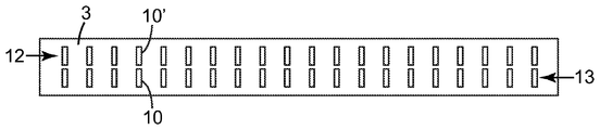
일부 실시예에서, 다이 오리피스는 도 3 및 도 4에 도시된 예시적인 실시예에서와 같이, 단일 행으로 배열될 수 있다. 일부 실시예에서, 행은 동일 선상에 있는 오리피스로 구성될 수 있으며(도 3 및 도 4에서와 같음), 이는 모든 오리피스의 수직 중심점이 적어도 본질적으로 다이의 횡축과 정렬되는 직선 상에 있음을 의미한다. (이와 관련하여, 오리피스의 수직 중심점은 오리피스의 장축을 따라, 오리피스의 "최상부" 및 "최하부" 단부들 사이의 중간에 있는 점이다. 수직 중심점(CPv)이 도 4에 표시된다.) 일부 실시예에서, 일 세트의 오리피스가 엇갈린 행일 수 있으며, 이는 오리피스 세트의 수직 중심점이 동일 선상에 있지 않음을 의미한다. 그러나, 임의의 세트의 오리피스(예컨대 편위된 또는 엇갈린 행)가 그러한 세트의 오리피스들 사이에 적어도 어느 정도의 측방향 중첩이 있는 한(즉, 그러한 세트의 오리피스들 각각의 임의의 부분을 통과하는, 다이의 횡축과 정렬되는 직선이 그려질 수 있으면) 여전히 단일 행으로 고려된다. 그러한 행의 엇갈림의 정도는 평균하여, 그러한 행의 오리피스들 사이의 측방향 중첩의 양에 의해 측정될 수 있다. 이러한 측방향 중첩은 적어도 하나의 다른 오리피스와 측방향으로 중첩하는 (다이의 높이 축을 따른) 오리피스의 수직 높이의 백분율로 표현될 수 있다(직선이 임의의 다른 오리피스와 접촉하는지 여부를 보기 위해 오리피스의 수직 높이를 따른 점으로부터 다이의 횡축을 따라 그러한 직선을 연장시킴으로써 평가되는 바와 같음). 도 3의 예시적인 배열의 측방향 중첩은 당연히 100%이다. 다른 실시예에서, 일 세트의 다이 오리피스의 측방향 중첩은 예컨대 적어도 약 95, 90, 85, 80, 75, 또는 50%일 수 있다.In some embodiments, the die orifices may be arranged in a single row, as in the exemplary embodiment shown in Figs. In some embodiments, the rows may consist of orifices that are collinear (as in Figures 3 and 4), meaning that the vertical center point of all orifices is at least essentially on a line aligned with the transverse axis of the die do. (In this regard, the vertical center point of the orifice is the point midway between the "top" and "bottom" ends of the orifice along the long axis of the orifice.) The vertical center point CP v is shown in FIG. In an embodiment, a set of orifices may be a staggered row, which means that the vertical center point of the orifice set is not collinear. However, as long as any set of orifices (e.g., deviated or staggered rows) have at least some lateral overlap between such sets of orifices (i. E., Through any portion of each of such sets of orifices, If a straight line aligned with the transverse axis of the die can be drawn) is still considered as a single row. The degree of such staggering can be averaged, by the amount of lateral overlay between the orifices of such rows. This lateral overlay can be expressed as a percentage of the vertical height of the orifice (along the height axis of the die) that laterally overlaps the at least one other orifice (to determine whether the straight line contacts any other orifice, As estimated by extending such straight line along the abscissa of the die from the point along the vertical height). The lateral overlay of the exemplary arrangement of Figure 3 is of course 100%. In other embodiments, the lateral overlay of a set of die orifices may be at least about 95, 90, 85, 80, 75, or 50%, for example.
전술된 측방향 중첩을 나타내지 않는 임의의 세트의 오리피스가 2개의(또는 그 초과의) 별개의 행으로 고려될 수 있다. 임의의 적합한 개수의 행의 오리피스가 원하는 대로 사용될 수 있다. 그러나, 다양한 특정 실시예에서, 행의 개수는 4개 미만, 3개 미만, 또는 2개 미만(즉, 위에서 논의된 바와 같은 단일 행)일 수 있다. 하나의 특정한 예시적인 실시예가 도 6에 도시된다. 이러한 실시예에서, (약 25 mm 이하의 에지간 거리를 고려할 때) 위에 개시된 바와 같이 측방향으로 인접한 다이 오리피스를 각각 포함하는 2개의 행의 오리피스(12, 13)가 제공된다. 따라서, 도 6의 설계는 본 명세서에 개시된 바와 같은 오리피스의 측방향으로 정렬된 패턴의 기준을 충족시킨다.Any set of orifices that do not exhibit the lateral overlay described above can be considered as two (or more) distinct rows. Any suitable number of rows of orifices may be used as desired. However, in various specific embodiments, the number of rows may be less than 4, less than 3, or less than 2 (i.e., a single row as discussed above). One specific exemplary embodiment is shown in Fig. In this embodiment, two rows of
도 6의 특정 설계에서, 2개의 행의 오리피스는 수직으로 적층된 세트(이 경우에, 쌍)로서 제공되며, 이는 일 세트의 오리피스가 다이의 높이 축을 따라 서로 정렬됨을 의미한다. 그러한 설계는 본 명세서에 개설된 조건이 충족되는 한 측방향으로 정렬된 오리피스 패턴의 정의 내에 속할 것이다. 도 6에 도시된 일반 유형의 설계에서, 수직으로 적층된 쌍의 최하부 오리피스(예컨대, 오리피스(10))의 상부 에지와 그러한 쌍의 최상부 오리피스(예컨대, 오리피스(10'))의 하부 에지 사이의 수직 거리가 감소되기 때문에, 수직으로 적층된 오리피스 쌍이 2개의 오리피스에 의해 조합되어 제공되는 총 높이와 전체 종횡비를 갖는 단일 오리피스에 더욱 가깝게 기능할 것이 인식될 것이다. 임의의 적합한 개수의 수직으로 적층된 오리피스가 사용될 수 있다. 다양한 실시예에서, 일 세트의 수직으로 적층된 오리피스가 2개(도 6에서와 같음), 3개, 또는 4개의 오리피스를 포함할 수 있다. 다양한 실시예에서, 수직으로 적층된 세트의 오리피스의 오리피스들 사이의 수직 에지간 거리는 평균하여 약 8, 4, 3, 또는 2 mm 이하일 수 있다.In the particular design of Figure 6, the two rows of orifices are provided as vertically stacked sets (in this case, pairs), which means that a set of orifices are aligned with one another along the height axis of the die. Such a design would fall within the definition of a laterally aligned orifice pattern as long as the conditions outlined herein are met. In the general type of design shown in Fig. 6, the upper edge of a vertically stacked pair of bottom orifices (e.g., orifice 10) and the bottom edge of such a pair of top orifices (e.g., orifice 10 ' It will be appreciated that because the vertical distance is reduced, vertically stacked orifice pairs will function more closely with a single orifice having a total height and total aspect ratio provided by the two orifices in combination. Any suitable number of vertically stacked orifices may be used. In various embodiments, a set of vertically stacked orifices may include two (as in FIG. 6), three, or four orifices. In various embodiments, the vertical edge-to-edge distance between the orifices of vertically stacked sets of orifices may be on the average about 8, 4, 3, or 2 mm or less.
발포 다이(1)는 오리피스(10)가 임의의 원하는 방식으로 제공되는 임의의 적합한 구성을 가질 수 있다. 다이 오리피스의 폭, 높이 및 간격은 원하는 대로 (예컨대 오리피스를 통한 용융된 유체 유동의 방향을 따른 오리피스의 길이와 조합되어) 선택될 수 있다. 다이 오리피스를 통한 적절한 압력 강하가 달성되는 것을 제공하기 위해, 이들이 예컨대 용융된 압출물의 처리량 및 다른 설계 및 작동 파라미터와 조합되어 선택될 수 있는 것이 인식될 것이다. 즉, 그러한 파라미터는 용융된 발포성 조성물이, 용융된 발포성 조성물 내에 존재하는 발포제의 적어도 상당한 양이 조기에(예컨대, 용융된 발포성 유동스트림(1010)이 다이 오리피스(10)를 통해 다이(1)로부터 배출되기 전에) 팽창되지 않기에 충분히 높은 압력으로 다이 내에서 유지되는 것을 제공하도록 조절될 수 있다. (발포 제품의 원하는 특성이 달성되는 한 다이 오리피스 내에서의 발포제의 어느 정도 양의 팽창이 허용될 수 있다.)The foam die 1 may have any suitable configuration in which the
발포 다이의 구성Composition of foam die
이와 관련하여, 정의상 발포 다이가 압출의 통상의 요건(예컨대, 고온을 견디는 것, 용융된 중합체 유동스트림의 누출을 나타내지 않는 것 등)을 충족시킬 수 있는 것에 더하여, 또한 발포 공정에서 발생하는 공정 조건을 견뎌야 하는 것에 유의하여야 한다. 구체적으로, 발포 다이는 유용한 발포체를 형성하는 능력에 허용불가하게 영향을 미칠 정도로 활성화된 (예컨대, 기체 또는 증기) 발포제의 누출을 나타내지 않아야 한다(달리 말하면, 발포 다이는 활성화된 발포제를 용융된 유기 중합체 재료와 용액 상태로 유지시키기에 충분한 내부 압력을 유지시킬 수 있어야 함). 따라서, 발포 다이는 그로부터 (액상의, 용융된 유동스트림에 더하여) 기체/증기의 누출을 방지하거나 최소화시키는 향상된 능력을 보유하여야 한다. 따라서, 통상적인 압출 다이가, 다이가 그러한 능력을 보유한다는 특정 정보가 없을 때에는, 반드시 발포 다이로 고려될 수 있지는 않을 수 있는 것에 유의하여야 한다.In this regard, in addition to being capable of meeting the usual requirements of extrusion (e. G., To withstand high temperatures, do not exhibit leakage of molten polymer flow streams, etc.), the foam die by definition also includes process conditions . Specifically, the foam die should not exhibit leakage of the activated (e.g., gas or vapor) blowing agent to an extent that unacceptably affects the ability to form useful foams (in other words, the foam die is an activated foaming agent, It must be able to maintain an internal pressure sufficient to keep it in solution with the polymeric material). Thus, the foam die must have an enhanced ability to prevent or minimize gas / vapor leakage therefrom (in addition to the liquid, molten flow stream). Thus, it should be noted that a conventional extrusion die may not necessarily be considered a foam die when there is no specific information that the die possesses such capability.
일부 실시예에서, 오리피스(10)는 예컨대 시트(sheet)(이러한 용어는 광범위하게 사용되며, 예컨대 엄격히 평탄한 구성을 필요로 하지 않음) 내에 임의의 원하는 방식으로(예컨대 방전 기계가공, 레이저 커팅, 워터 커팅(water cutting) 등에 의해) 제공되는 관통-개구일 수 있다. 시트는 적합한 재료(예컨대, 금속)로 그리고 발포 압출에 비례한 압력과 힘을 견디기에 적합한 두께로 제조될 수 있다. 그러한 시트의 두께는 위에 언급된 바와 같이 원하는 오리피스 길이를 달성하도록 선택될 수 있다(또는, 오리피스가 제공되도록 의도되는 시트의 특정 영역이 예컨대 기계가공 또는 커팅에 의해 감소된 그의 두께를 가질 수 있음). 발포 다이를 형성하기 위해, 그러한 시트가 예컨대 하나 이상의 다이 공동을 포함하는 주 본체에 접속되되, (예컨대 적어도 하나의 압출기로부터) 다이 공동에 전달되는 용융된 유동스트림이 다수의 유동스트림으로 분할된 다음에 다이 오리피스에 전달될 수 있도록 오리피스가 다이 공동과 유체 연통하는 방식으로 접속될 수 있다.In some embodiments, the
일부 실시예에서, 발포 다이(1)는 압력 하에서 함께 층을 이루어 심 스택(shim stack)을 형성하는 복수의 심에 의해 적어도 부분적으로 제공될 수 있다. 특정 실시예에서, 각각의 심은 발포 다이의 높이 축(h)에 적어도 실질적으로 평행한 주 평면을 나타낼 수 있다. 그러한 심은 조합되어 집합적으로 발포 다이의 다이 오리피스를 한정하고, 발포 다이의 주 본체를 한정하며, 또한 다이 오리피스들 중 적어도 일부에 유체적으로 연결되는(fluidly connected) (주 본체 내의) 적어도 하나의 다이 공동을 한정할 수 있다. 심-스택 다이의 더욱 많은 상세 사항은 본 명세서에 전체적으로 참고로 포함되는, 발명의 명칭이 심-스택 발포 다이(Shim-Stack Foaming Die)(대리인 관리 번호 75788US002)인, 본 출원과 동일자로 출원된, 공히 계류중인 미국 가특허 출원 제62/067890호에서 찾아볼 수 있다.In some embodiments, the foam die 1 may be at least partially provided by a plurality of shims layered together under pressure to form a shim stack. In certain embodiments, each shim may represent a major plane that is at least substantially parallel to the height axis (h) of the foam die. Such shims are combined to collectively define the die orifices of the foam die, define the main body of the foam die, and also include at least one fluidly connected (in the main body) fluidly connected to at least a portion of the die orifices It is possible to define a die cavity. Further details of the shim-stack die may be found in US patent application Ser. No. 10 / 392,134, filed on even date herewith, which is incorporated herein by reference in its entirety, which is assigned to the same assignee as Shim-Stack Foaming Die (Attorney Docket No. 75788US002) , Pending U.S. provisional patent application No. 62/067890.
재료material
발포 다이(1)는 임의의 적합한 발포제와 조합되어 임의의 원하는 유기 중합체 재료를 포함하는 임의의 적합한 용융된 발포성 조성물을 처리하기 위해 사용될 수 있다. 적합한 유기 중합체는 예컨대 하나 이상의 단일중합체, 공중합체(랜덤(random), 블록(block), 그라프트(graft) 등이든 간에), 다양한 단일중합체 또는 공중합체의 혼합물 또는 블렌드 등을 포함하는, 임의의 열가소성 (용융-압출가능) 조성물로부터 선택될 수 있다. 특정 실시예에서, 임의의 그러한 중합체는 필요할 경우 (예컨대, 보다 높은 용융 강도를 제공하기 위해) 분지형일 수 있다. 적합한 유기 중합체는 예컨대 폴리올레핀, 폴리에스테르, 폴리아크릴, 폴리아미드, 폴리카르보네이트, 폴리우레탄, 폴리스티렌 등으로부터 선택될 수 있다. 임의의 적합한 첨가제가, 그러한 첨가제가 조성물의 발포 능력과 허용불가하게 간섭되지 않는 한 포함될 수 있다. 예를 들어, 하나 이상의 무기 첨가제, 예컨대, 광물 충전제, 강화 충전제, 안료 등이 사용될 수 있다(예컨대, 활석, 실리카, 점토, 티타니아, 유리 섬유, 유리 버블(glass bubble), 소판(platelet), 나노입자, 나노튜브(nanotube) 등). 다른 첨가제는 산화방지제, 자외선 흡수제, 사슬 연장제, 정전기 방지제, 장애 아민 광 안정제, 가수분해 안정제, 핵형성제(nucleating agent), 가공조제, 난연제, 착색제, 슬립제(slip agent) 등을 포함할 수 있다. 임의의 이들 첨가제가 임의의 원하는 조합으로 사용될 수 있다.The foam die 1 may be used in combination with any suitable blowing agent to treat any suitable fused foamed composition comprising any desired organic polymer material. Suitable organic polymers include any organic polymer, including, for example, one or more homopolymers, copolymers (whether random, block, graft, etc.), mixtures or blends of various homopolymers or copolymers, Thermoplastic (melt-extrudable) compositions. In certain embodiments, any such polymer may be branched if desired (e.g., to provide a higher melt strength). Suitable organic polymers may be selected from, for example, polyolefins, polyesters, polyacrylics, polyamides, polycarbonates, polyurethanes, polystyrenes, Any suitable additive may be included so long as such additive is not unintentionally interfered with the foaming ability of the composition. For example, one or more inorganic additives such as mineral fillers, reinforcing fillers, pigments and the like can be used (e.g., talc, silica, clay, titania, glass fiber, glass bubble, platelet, Particles, nanotubes, etc.). Other additives may include antioxidants, ultraviolet absorbers, chain extenders, antistatic agents, hinder amine light stabilizers, hydrolytic stabilizers, nucleating agents, processing aids, flame retardants, colorants, slip agents, have. Any of these additives may be used in any desired combination.
일부 실시예에서, 유기 중합체 재료는 폴리올레핀 재료일 수 있다. 적합한 폴리올레핀 재료의 비제한적인 목록은 예컨대 폴리프로필렌, 폴리에틸렌, 폴리부틸렌, 폴리(4-메틸-1-펜텐), 및 이들 중 임의의 것의 공중합체 및 블렌드를 포함한다.In some embodiments, the organic polymeric material may be a polyolefinic material. A non-limiting list of suitable polyolefin materials includes, for example, copolymers and blends of polypropylene, polyethylene, polybutylene, poly (4-methyl-1-pentene), and any of these.
일부 실시예에서, 유기 중합체 재료는 폴리에스테르 재료일 수 있다. "폴리에스테르"란 적어도 약 70 중량%의 유기 중합체 재료가 에스테르 결합을 갖는 단일중합체 및/또는 공중합체인 임의의 재료를 의미한다. 다양한 실시예에서, 에스테르-결합 중합체 사슬은 재료의 중량의 적어도 약 80%, 적어도 약 90%, 적어도 약 95%, 적어도 약 98%, 또는 적어도 99.5%를 구성한다. 다양한 실시예에서, 폴리에스테르는 적어도 70 중량%가 폴리에틸렌 테레프탈레이트이거나, 적어도 80 중량%가 폴리에틸렌 테레프탈레이트이거나, 적어도 90 중량%가 폴리에틸렌 테레프탈레이트이거나, 적어도 95 중량%가 폴리에틸렌 테레프탈레이트이다. 추가의 실시예에서, 폴리에스테르 재료는 폴리에틸렌 테레프탈레이트로 본질적으로 구성되며, 이러한 조건은 에틸렌 글리콜 이외의 글리콜로부터 유도되는 소량(예컨대, 약 2.0 몰% 미만)의 단량체 단위의 존재를 배제하지 않는 것으로 이해될 것이다.In some embodiments, the organic polymer material may be a polyester material. By "polyester" is meant any material wherein at least about 70 weight percent of the organic polymeric material is a homopolymer and / or copolymer having an ester bond. In various embodiments, the ester-binding polymer chain constitutes at least about 80%, at least about 90%, at least about 95%, at least about 98%, or at least 99.5% by weight of the material. In various embodiments, the polyester is at least 70 wt.% Polyethylene terephthalate, or at least 80 wt.% Polyethylene terephthalate, or at least 90 wt.% Polyethylene terephthalate, or at least 95 wt.% Polyethylene terephthalate. In a further embodiment, the polyester material consists essentially of polyethylene terephthalate, and this condition does not exclude the presence of small amounts (e.g., less than about 2.0 mol%) of monomer units derived from glycols other than ethylene glycol It will be understood.
적합한 폴리에스테르는 예컨대 하이드록실-함유 단량체 및/또는 올리고머(예컨대, 사슬 연장제)와 폴리-산-함유 또는 폴리-에스테르-함유 단량체 및/또는 올리고머(예컨대, 테레프탈산, 아이소프탈산, 나프탈렌 다이카르복실레이트 등과 같은 다이카르복실산 또는 다이에스테르)의 축합 중합에 의해 통상적으로 제조되는 것들을 포함한다. 그러한 폴리에스테르는 폴리-산으로부터, 또는 그러한 재료의 임의의 에스테르-형성 등가물로부터(예컨대, 중합되어 궁극적으로 폴리에스테르를 제공할 수 있는 임의의 재료로부터) 제조될 수 있다. 그러한 폴리에스테르는 임의의 적합한 하이드록실-함유 사슬 연장제 또는 연장제들의 조합으로부터 제조될 수 있다. 통상적으로 사용되는 사슬 연장제는 예를 들어 2-탄소 다이올, 에틸렌 글리콜(2G, 테레프탈산 또는 에스테르와 중합될 때 폴리에스테르 "2GT"를 산출함); 3-탄소 다이올, 1,3-프로판다이올(3G, 테레프탈산 또는 에스테르와 중합될 때 폴리에스테르 "3GT"를 산출함); 및 4-탄소 다이올, 1,4-부탄다이올(4G, 테레프탈산 또는 에스테르와 중합될 때 폴리에스테르 "4GT"를 산출함)을 포함한다. 2GT에 대해 사용되는 다른 명칭은 폴리에틸렌 테레프탈레이트 또는 PET이고, 3GT에 대해서는 트라이메틸렌 테레프탈레이트(PTT) 또는 폴리프로필렌 테레프탈레이트(PPT)이고, 4GT에 대해서는 폴리부틸렌 테레프탈레이트 또는 PBT이다. 폴리에스테르는 예컨대 임의의 적합한 폴리-산-함유 또는 폴리-에스테르-함유 단량체 또는 올리고머 또는 이들의 조합으로부터 제조될 수 있다. 일부 실시예에서, 그러한 단량체 또는 올리고머는 생성되는 폴리에스테르가 방향족 폴리에스테르이도록 선택될 수 있고; 다른 실시예에서, 그들은 생성되는 폴리에스테르가 지방족 폴리에스테르이도록 선택될 수 있다. 위의 폴리에스테르들 중 임의의 것의 블렌드(예컨대, 방향족과 지방족의 블렌드)가 지방족/방향족 공중합체일 수 있는 바와 같이 사용될 수 있다.Suitable polyesters include, for example, hydroxyl-containing monomers and / or oligomers (such as chain extenders) and poly-acid-containing or poly-ester- containing monomers and / or oligomers (e.g., terephthalic acid, isophthalic acid, naphthalenedicarboxylic Such as dicarboxylic acids or diesters, such as alcohols, ethers, ethers, ethers, and the like. Such polyesters can be prepared from poly-acids, or from any ester-forming equivalents of such materials (e.g., from any material that can be polymerized and ultimately provide polyester). Such polyesters may be prepared from any suitable hydroxyl-containing chain extender or combination of extenders. Commonly used chain extenders include, for example, 2-carbon diols, ethylene glycols (yielding the polyester "2GT" when polymerized with 2G, terephthalic acid or an ester); 3-carbon diol, 1,3-propanediol (yielding polyester "3GT" when polymerized with 3G, terephthalic acid or ester); And 4-carbon diol, 1,4-butanediol (yielding 4G, polyester "4GT" when polymerized with terephthalic acid or an ester). Other names used for 2GT are polyethylene terephthalate or PET, trimethylene terephthalate (PTT) or polypropylene terephthalate (PPT) for 3GT and polybutylene terephthalate or PBT for 4GT. The polyesters can be prepared, for example, from any suitable poly-acid-containing or poly-ester-containing monomers or oligomers or combinations thereof. In some embodiments, such monomers or oligomers can be selected such that the resulting polyester is an aromatic polyester; In another embodiment, they can be selected so that the resulting polyester is an aliphatic polyester. Blends of any of the above polyesters (e.g., aromatic and aliphatic blends) may be used as may be aliphatic / aromatic copolymers.
(발포성 조성물뿐만 아니라, 고밀화된, 예컨대 비-발포성 조성물에도 사용하기에) 유용할 수 있는 폴리에스테르의 추가의 상세 사항은 본 명세서에 전체적으로 참고로 포함되는, 발명의 명칭이 "폴리에스테르 기재를 접합시키는 방법(Methods of Bonding Polyester Substrates)"인, 미국 특허 출원 공개 제2015/0047774호로서 2015년 2월 19일자로 공개된 미국 특허 출원 제14/363132호에 기술된다. 폴리에스테르가 발포성 조성물에 사용되는 특정한 경우에, 발포성 조성물이 (예컨대, 용융된 조성물의 용융 강도를 향상시키기 위해) 사슬 연장제를 포함하는 것이 유리할 수 있다. 흔히, 무수물, 예컨대 프탈산 무수물, 말레산 무수물, 또는 피로멜리트산 이무수물(PMDA), 및/또는 화합물, 예컨대 소정의 아지리딘, 에폭사이드 및 다이아민이 그러한 목적을 위해 사용된다.Further details of the polyester that may be useful (for use in foamable compositions as well as for densified, e.g., non-foamable compositions) may also be found in U.S. Patent Application Serial No. 10 / &Quot; Methods of Bonding Polyester Substrates ", U.S. Patent Application Publication No. 14/363132, published February 19, 2015, as U.S. Patent Application Publication No. 2015/0047774. In certain cases where the polyester is used in a foamable composition, it may be advantageous for the foamable composition to include a chain extender (e.g., to improve the melt strength of the molten composition). Often, anhydrides such as phthalic anhydride, maleic anhydride, or pyromellitic acid dianhydride (PMDA), and / or compounds such as certain aziridines, epoxides and diamines are used for such purposes.
용융된 발포성 조성물은 임의의 적합한 발포제(때때로 포밍제(foaming agent)로 지칭됨)를 임의의 효과적인 양으로 포함할 수 있다. 그러한 발포제는 흔히 물리적 발포제(임의의 화학적 반응 없이, 물리적 상변화, 예컨대 휘발 또는 증발을 겪는 분자를 의미함)로서 또는 화학적 발포제(화학적 반응이 기체 또는 휘발성 분자를 유리시키기 위해 전형적으로 발생함)로서 넓게 분류된다. 물리적 발포제의 비제한적인 예는 다양한 기체(예컨대, 아르곤, 헬륨, 질소, 이산화탄소 등)를 포함한다. 추가의 예는 탄화수소, 예컨대 다양한 프로판, 부탄, 펜탄, 헵탄 등을 포함하는 휘발성 액체를 포함한다. 그러한 물리적 발포제는 예컨대 압력 하에서(액체로서든 또는 기체로서든 간에) 중합체 용융물 또는 초기 용융물(예컨대, 압출기의 배럴(barrel) 내의) 내에 주입될 수 있다. 화학적 발포제의 비제한적인 예는 예컨대 아조다이카본아미드, 옥시비스(벤젠 설포닐하이드라지드), 페닐 테트라졸, 및 예컨대 소듐 카르보네이트 및/또는 소듐 바이카르보네이트를 포함하는 알칼리 카르보네이트를 포함한다. 그러한 제제는 예컨대 압출기 내에 예컨대 용융물 첨가제로서 삽입될 수 있고, 압출되도록 요구되는 유기 중합체 재료와 사전혼합될 수 있으며, 기타 등등일 수 있다. 임의의 유형의 임의의 발포제의 혼합물이 원하는 대로 사용될 수 있다. 다양한 실시예에서, 발포제(또는 2가지 이상의 발포제의 조합)이 적어도 약 0.1, 0.5, 1.0, 2.0, 또는 4.0 중량 퍼센트 내지 최대 약 20, 15, 10, 8.0, 또는 6.0 중량 퍼센트의 수준으로 발포성 조성물 내에 존재할 수 있다.The molten foamable composition may contain any suitable foaming agent (sometimes referred to as a foaming agent) in any effective amount. Such blowing agents are often referred to as physical blowing agents (meaning any molecules that undergo physical phase changes, such as volatilization or evaporation, without any chemical reaction) or as chemical blowing agents (a chemical reaction typically occurs to liberate gaseous or volatile molecules) It is classified broadly. Non-limiting examples of physical blowing agents include various gases (e.g., argon, helium, nitrogen, carbon dioxide, etc.). Further examples include hydrocarbons, such as volatile liquids including various propane, butane, pentane, heptane and the like. Such physical blowing agents may be injected, for example, under pressure (whether liquid or gaseous) into a polymer melt or an initial melt (e.g., in a barrel of an extruder). Non-limiting examples of chemical foaming agents include, for example, azodicarbonamide, oxybis (benzenesulfonylhydrazide), phenyltetrazole, and alkali carbonates including, for example, sodium carbonate and / or sodium bicarbonate . Such formulations may be, for example, inserted into the extruder as a melt additive, premixed with the organic polymer material desired to be extruded, and so forth. Mixtures of any type of foaming agent may be used as desired. In various embodiments, the foamable composition (or combination of two or more blowing agents) is at a level of at least about 0.1, 0.5, 1.0, 2.0, or 4.0 weight percent up to about 20, 15, 10, Lt; / RTI >
압출 장치Extrusion device
발포 다이(1)는 임의의 적합한 압출 장치와 함께 사용될 수 있다. 하나의 예시적인 압출 장치가 도 2에 도시된다. 발포 다이(1)는 정의상 예컨대 용융된 발포성 조성물을 포함하는 용융된 발포성 유동스트림을 수용하도록 구성되는 적어도 하나의 다이 공동을 포함할 것이다. 압출기가 용융된 발포성 유동스트림을 다이(1)의 다이 공동에 전달하기 위해 사용될 수 있다. 이는 필요할 경우 기어 펌프(512)를 통해 그리고/또는 피드블록(feedblock)(513)을 통해 수행될 수 있다(따라서, 압출기로부터 용융된 유동스트림을 수용하는 다이 공동의 개념이 예컨대 기어 펌프 및/또는 피드블록 또는 임의의 다른 보조 장비가 유동스트림을 압출기 출구로부터 다이 공동에 전달하기 위해 사용되는 경우를 포함함). 흔히 발포성 조성물을 수반하는 압출에서, 2개의 압출기를 종렬로(in tandem) 포함하는 압출 장치를 사용하는 것이 편리할 수 있으며, 여기서 제1 압출기(511)(예컨대 상대적으로 높은 압축비로 작동함)가 원하는 조성물을 용융시키고 이러한 용융된 조성물을 제2 압출기(510)에 전달하기(직접 또는 기어 펌프를 통해 등이든 간에) 위해 사용되고, 이러한 제2 압출기(예컨대, 상대적으로 낮은 압축비로 작동함)는 주로 계량(metering) 및/또는 냉각 기능을 수행할 수 있다. 일부 실시예에서, 압출 장치는 본 명세서에서 추후에 더욱 상세히 논의되는 바와 같이, 예컨대 상이한 다이 공동에 상이한 용융된 조성물을 제공하도록 병렬로(in parallel) 작동되는 2개의 압출기(또는 종렬 압출기의 2개의 쌍)를 포함할 수 있다.The foam die 1 may be used with any suitable extrusion apparatus. One exemplary extrusion apparatus is shown in Fig. The foam die 1 will, by definition, include at least one die cavity configured to receive a molten expanded flow stream comprising, for example, a molten foamable composition. An extruder may be used to deliver the molten expanded flow stream to the die cavity of the
필요할 경우, 압출 장치는 하나 이상의 발포제를 용융된 또는 초기 용융된 조성물 내에 주입하여 조성물이 발포성 조성물이 되도록 하기 위해 사용될 수 있는 하나 이상의 발포제 투입 포트(514)를 포함할 수 있다. 도 2의 예시적인 실시예에 압출기(514) 상에 위치된 것으로 도시되지만, 그러한 발포제 투입 포트는 압출 장치의 임의의 적합한 위치에(예컨대 압출기의 길이를 따라; 또는, 종렬 압출기 구성이 사용되면, 어느 한 압출기 또는 압출기들 사이의 길이를 따라) 위치될 수 있다.If desired, the extrusion device may include one or more blowing
적어도 일부 실시예에서, 발포 다이(1)는 용융된 발포성 압출물 유동스트림(1010)을 성형 공동의 내부가 아닌 한정되지 않은 공간(undefined space)(도 2에 도시된 바와 같음) 내로 연속적으로 방출하도록 구성될 수 있다. 즉, 그러한 실시예에서, 압출/합체 공정은 예컨대 용융된 발포성 조성물이 사출 성형 공동(예컨대 하나 이상의 스프루(sprue), 게이트(gate) 등을 제외하고는 예컨대 모든 면에 완전히 경계가 설정됨) 내에 배치식으로(in batches) 주기적으로 전달되는 사출-성형 작업이기보다는 연속 발포 슬래브(1100)를 생성하는 연속 공정이다. 따라서, 일부 실시예에서, 다이(1)는 용융된 압출물을 "외기(open air)" 중으로 압출하기 위해 사용될 수 있으며, 합체된 스트림이 이어서 예컨대 이동 벨트(어떠한 도면에도 도시되지 않음) 상에 수집된다. 그러나, 필요할 경우, 하나 이상의 발포 플레이트가 예컨대 비교적 매끄러운 주 표면을 가진 적어도 대체로 직사각형 슬래브로서의 발포 슬래브의 생성을 향상시키기 위해, 예컨대 초기 발포 슬래브의 한쪽 또는 양쪽 주 표면에 근접하게 제공될 수 있다. 필요할 경우, 용융된 압출물이 2개의 이동 벨트들 사이의 공간 내에(예컨대 이른바 이중-벨트 프레스(double-belt press) 내에) 전달될 수 있으며, 이는 발포 슬래브의 표면의 평활도를 향상시킬 수 있고/있거나 발포 슬래브의 두께를 원하는 대로 제어할 수 있다. 발포 플레이트(당업계에서 때때로 캘리브레이터(calibrator)로 지칭됨) 또는 이중-벨트 프레스의 사용은 공동 내로의 배치식(batchwise) 사출 성형과 구별된다. 특정 실시예에서, 발포 플레이트 또는 플레이트들, 또는 이중-벨트 프레스가 다이(1)와 함께 사용되지 않는다.In at least some embodiments, the foam die 1 continuously discharges the molten expanded
용융된 압출물/초기 발포체가 그 내부로 방출되는 환경은 초기 발포체의 팽창의 비율 또는 양, 초기 발포체의 셀의 성장/합체/붕괴 등에 적절히 영향을 미치는 임의의 방식으로 제어될 수 있다. 적합한 파라미터는 예컨대 전체 압력, 용융된 압출물이 그 내부로 방출되는 기체 환경 내의 특정 기체의 농도, 및/또는 그러한 환경의 온도를 포함할 수 있다. 따라서, 예를 들어, 용융된 압출물이 테이크어웨이 벨트 상에 또는 이중-벨트 라미네이션(dual-belt lamination)의 2개의 벨트들 사이에 수집되면, 벨트(들)의 온도가 원하는 대로 제어될 수 있다. 또는, 용융된 압출물이 그 내부로 방출되는 공기(또는 일반적으로, 기체) 환경의 온도가 원하는 대로 제어될 수 있다.The environment in which the molten extrudate / initial foam is discharged into it can be controlled in any manner that adequately affects the rate or amount of expansion of the initial foam, growth / coalescence / collapse of the cells of the initial foam, and the like. Suitable parameters may include, for example, the total pressure, the concentration of the particular gas in the gaseous environment into which the molten extrudate is discharged, and / or the temperature of such an environment. Thus, for example, if the molten extrudate is collected on two take-away belts or between two belts of a dual-belt lamination, the temperature of the belt (s) can be controlled as desired . Alternatively, the temperature of the air (or gaseous) environment in which the molten extrudate is discharged into it can be controlled as desired.
다이(1)의 배향(용융된 스트림이 그를 따라 예컨대 한정되지 않은 공간 내로 압출되는 방향을 한정함)은 원하는 대로 임의의 방향일 수 있다. 즉, 압출이 반드시 지면에 대해 완전히 수평 방향, 또는 완전히 수직 방향으로 이루어질 필요는 없다. 수직, 높이, 최상부, 최하부 등과 같은 용어의 본 명세서에서의 사용이 예컨대 도 3 내지 도 5에 관한 설명의 편의를 위한 것이고, 지면에 대한 임의의 특정 배향을 암시하지 않는 것이 강조된다.The orientation of the die 1 (which defines the direction along which the molten stream is extruded into, for example, an unconstrained space) may be any direction as desired. That is, extrusion does not necessarily have to be completely horizontal or completely perpendicular to the ground. It should be emphasized that the use herein of terms such as vertical, height, top, bottom, and the like is for convenience of discussion with respect to, for example, Figs. 3 to 5, and does not imply any particular orientation to the ground.
라미네이션Lamination
일부 실시예에서, 기재(substrate)(예컨대, 시트형(sheetlike) 기재)가 단일체 발포 슬래브(1100)의 주 표면에 라미네이팅될 수 있다. 이는 임의의 원하는 라미네이션 방법을 사용하여, 예컨대 접착제 등의 사용에 의해 임의의 적합한 방식으로 수행될 수 있다. 특정 실시예에서, 그러한 라미네이션을 인라인(in-line)으로 수행하는 것이 유리할 수 있으며, 이는 다이(1) 및 압출 장치와 인라인으로 물리적으로 동일 장소에 배치되는 라미네이팅 장치의 사용에 의해, 실질적으로 슬래브(1100)가 유동스트림(1010)의 합체에 의해 생성된 직후에 기재가 슬래브(1100)에 라미네이팅됨을 의미한다. 이는 예컨대 슬래브(1100)가 생성된 다음에 슬래브가 라미네이션 장치로 이동되어 그에 기재를 라미네이팅할 때까지 보관되는 계획과 대조될 수 있다. 임의의 적합한 접합 방법이 사용될 수 있지만, 그러한 인라인 라미네이션은 유리하게는 예컨대 기재(접합 공정을 용이하게 하기 위해 그 자체가 가열될 수 있음)와 슬래브(1100)의 주 표면 사이의 용융-접합을 향상시키기 위해 슬래브(1100)가 완전히 냉각 및/또는 고화되기 전에 수행될 수 있다. 일부 실시예에서, 적어도 슬래브(1100)의 주 표면과 슬래브(1100)의 표면에 접합되도록 의도되는 기재의 주 표면이 서로 용융-접합가능하다. 용융-접합가능한 재료의 추가의 태양이 복합 발포 슬래브의 주 상 및 부 상의 논의에서 본 명세서의 다른 곳에서 논의된다. 이들 논의와 예시적인 재료의 목록이 간결함을 위해 여기에 포함되지 않을 것이지만, 발포 슬래브(1100)의 주 표면에 라미네이팅될 수 있는 임의의 기재의 재료에 마찬가지로 적용가능한 것으로 간주되어야 한다.In some embodiments, a substrate (e.g., a sheetlike substrate) may be laminated to the primary surface of the
원하는 대로, 임의의 원하는 기재가 임의의 발포 슬래브에 라미네이팅될 수 있다. 적합한 기재는 예컨대 금속 포일(metal foil), 금속 메시(metal mesh), 무기 섬유질 웨브, 예컨대 유리섬유 또는 암면(rockwool) 등으로부터 선택될 수 있다. 일부 실시예에서, 라미네이팅될 기재는 유기 중합체 기재일 수 있다. 특정 실시예에서, 그러한 기재는 임의의 적합한 조성의 섬유질 재료, 예컨대 천(fabric), 부직 웨브(nonwoven web), 직조 또는 편직 웨브(woven or knitted web), 스크림(scrim) 또는 네팅(netting) 등일 수 있다. 일부 실시예에서, 그러한 기재는 반응성 재료가 사전-함침된 섬유질 재료일 수 있다(예컨대, 그것은 에폭시와 같은 "프리-프레그(pre-preg)"를 포함하는 유리-섬유 기재일 수 있음). 일부 실시예에서, 기재는 임의의 적합한 조성의 유기 중합체 필름 또는 시트(예컨대 섬유-강화 필름 또는 시트를 포함함)일 수 있다. 특정 실시예에서, 그러한 필름은 폴리에스테르 필름, 예컨대 이축-배향(biaxially-oriented) 폴리에스테르 필름일 수 있다. 특정 실시예에서, 발포 슬래브에 라미네이팅되도록 의도되는 중합체 필름은 플래시램핑된(flashlamped) 필름일 수 있다. 필름을 플래시램핑할 수 있는 공정의 상세 사항은 본 명세서에 전체적으로 참고로 포함되는, 발명의 명칭이 "폴리에스테르 기재를 접합시키는 방법"인, 미국 특허 출원 공개 제2015/0047774호로서 2015년 2월 19일자로 공개된 미국 특허 출원 제14/363132호에 상세히 제시된다.As desired, any desired substrate may be laminated to any foamed slab. Suitable substrates may be selected from, for example, metal foils, metal meshes, inorganic fibrous webs such as glass fibers or rockwool, and the like. In some embodiments, the substrate to be laminated may be an organic polymer substrate. In certain embodiments, such substrates may be formed from any suitable composition of fibrous material, such as, for example, a fabric, a nonwoven web, a woven or knitted web, a scrim or a netting, . In some embodiments, such a substrate may be a pre-impregnated fibrous material (e.g., it may be a glass-fiber substrate comprising a "pre-preg" such as epoxy). In some embodiments, the substrate can be any suitable composition of organic polymer film or sheet (including, for example, a fiber-reinforced film or sheet). In certain embodiments, such a film may be a polyester film, such as a biaxially-oriented polyester film. In certain embodiments, the polymer film intended to be laminated to the foam slab may be a flashlamped film. Details of the process for flash ramming a film are described in U. S. Patent Application Publication No. 2015/0047774, entitled " Method of Attaching a Polyester Substrate, "filed February 2015, which is incorporated herein by reference in its entirety. ≪ / RTI > published in U. S. Patent Application Serial No. < RTI ID = 0.0 > 14/363132, < / RTI >
일부 실시예에서, 기재가 그에 라미네이팅되는 단일체 발포 슬래브는 아래에서 상세히 논의되는 바와 같이, 적어도 주 발포 상 및 예컨대 비-발포 재료로 제조될 수 있는 부 고밀화 상을 포함하는 단일체 복합 발포 슬래브일 수 있다. 일부 실시예에서, 그러한 복합 발포 슬래브의 부 상은 본 명세서에 기술된 바와 같이 하나 이상의 기다란 부재의 형태를 취할 수 있다. 일부 실시예에서, 그러한 복합 발포 슬래브의 부 상은 기재가 그에 라미네이팅되는 적어도 제1(및 선택적으로 제2) 표면 층의 형태를 취할 수 있다. 그러한 표면 층이, 예컨대 특정 기재가 그것이 발포 상에 접합될 수 있는 경우보다 더욱 쉽게 그에 접합될 수 있는 타이 층(tie layer)으로서 기능하는 것이 특히 유리할 수 있다. 예를 들어, 특정 실시예에서, 예컨대 폴리에틸렌 테레프탈레이트 주 발포 상(층)이 그에 라미네이팅되는 폴리에틸렌 테레프탈레이트 기재(예컨대, 필름 또는 부직 웨브)를 갖게 될 때, 예컨대 글리콜-개질된 폴리에틸렌 테레프탈레이트를 포함하는 타이 층이 사용될 수 있다. 일부 실시예에서, 제1 기재가 슬래브(1100)의 제1 주 표면에 라미네이팅될(예컨대, 용융-접합을 통해 인라인 라미네이팅될) 수 있고, 제2 기재가 유사하게 슬래브(1100)의 제2 주 표면에 라미네이팅될 수 있다.In some embodiments, the monolithic foam slab on which the substrate is laminated may be a monolithic composite foam slab comprising at least a main foamed phase and a sub-densified phase that can be made, for example, as a non-foamed material, as discussed in detail below . In some embodiments, a phase of such a composite foam slab may take the form of one or more elongate members as described herein. In some embodiments, a minority of such composite foamed slabs may take the form of at least a first (and optionally second) surface layer on which the substrate is laminated. It may be particularly advantageous for such a surface layer to function, for example, as a tie layer that can be bonded to it more easily than if, for example, a particular substrate could be bonded to the foam. For example, in certain embodiments, for example, when a polyethylene terephthalate master foaming phase (layer) has a polyethylene terephthalate substrate (e.g., a film or a nonwoven web) laminated thereto, for example, a glycol-modified polyethylene terephthalate May be used. In some embodiments, the first substrate may be laminated to the first major surface of the slab 1100 (e.g., to be in-line laminated through a melt-joint), and the second substrate may similarly be laminated to the second main surface of the
복합 발포 슬래브Composite foamed slab
일부 실시예에서, 본 명세서에 개시된 장치 및 방법은 이전에 정의된 바와 같은 주 발포 상 및 부 고밀화 상을 포함하는 복합 발포 슬래브를 제조하기 위해 사용될 수 있다. 일부 실시예에서, 다이(1)의 다이 오리피스는 발포성 조성물인 제1 용융된 조성물을 포함하는 제1 용융된 유동스트림을 수용하도록 구성되는 다이(1)의 제1 다이 공동에 유체적으로 연결되는 제1 세트의 다이 오리피스; 및 제2 용융된 조성물을 포함하는 제2 용융된 유동스트림을 수용하도록 구성되는 다이(1)의 제2 다이 공동에 유체적으로 연결되는 제2 세트의 다이 오리피스를 포함할 수 있다. 일부 실시예에서, 예컨대 압출 공정을 더욱 정교하게 제어할 수 있기 위해, 제1 및 제2 다이 공동과 다이 오리피스 세트를 통해 처리되는 제1 및 제2 용융된 조성물은 본질적으로 동일할 수 있다(예컨대, 동일한 압출기 또는 종렬 압출기 쌍에 의해 양쪽 다이 공동에 전달되는 단일 발포성 조성물). 다른 실시예에서, 제1 및 제2 용융된 조성물은 예컨대 복합 발포 슬래브인 발포 슬래브를 제조하기 위해 서로 상이할 수 있다. 그러한 실시예에서, 도 2의 예시적인 배열에 도시된 바와 같이, 제2 용융된 조성물은 제1 압출기(또는 종렬 압출기 쌍)와 상이한 제2 압출기로부터 제2 다이 공동에(그리고 그에 따라 제2 세트의 다이 오리피스에) 공급될 수 있다. 그러한 배열에서, 제1 다이 오리피스는 예컨대 복합 발포 슬래브의 주 발포 상을 생성하기 위해 사용될 수 있고, 제2 다이 오리피스는 예컨대 복합 발포 슬래브의 부 고밀화 상을 생성하기 위해 사용될 수 있다.In some embodiments, the apparatus and methods disclosed herein may be used to produce a composite foam slab comprising a main foamed phase and a sub-densified phase as previously defined. In some embodiments, the die orifice of
이러한 일반 유형의 일부 실시예에서, 제2 세트의 다이 오리피스가, 제2 세트의 적어도 선택된 다이 오리피스가 각각 제1 세트의 다이 오리피스의 한 쌍의 다이 오리피스들 사이에 개별적으로 측방향으로 개재되는 배열로 제공될 수 있다. 이러한 유형의 예시적인 배열이 도 8에 도시되며, 여기서 제2 다이 오리피스(10s)가 각각 한 쌍의 제1 다이 오리피스들(10f) 사이에 개별적으로 측방향으로 개재된다. 이러한 용어는 단일 제2 다이 오리피스(10s)가 2개의 제1 다이 오리피스들(10f) 사이에 측방향으로 위치되며, 이러한 제1 다이 오리피스(10f)가 제2 다이 오리피스(10s)를 제외하고는 그들 사이에 측방향으로 어떠한 오리피스도 갖지 않음을 의미한다. 도 8의 예시적인 배열에서, 제1 다이 오리피스(10f)는 모두 대체로 도그본 형상이며, 제2 다이 오리피스(10s)는 대체로 타원형 또는 직사각형 형상이고 또한 높이가 제1 다이 오리피스(10f)보다 약간 더 짧다. 그러나, 도 8의 다이 오리피스가 여전히 다이 오리피스의 측방향으로 정렬된 패턴의 기준을 충족시키는 것이 인식될 것이다.In some embodiments of this general type, a second set of die orifices may be arranged such that the at least selected die orifices of the second set are individually laterally interleaved between a pair of die orifices of the first set of die orifices Lt; / RTI > An exemplary arrangement of this type is shown in Figure 8, wherein the second die orifice (10 s) are interposed individually in the lateral direction between the first die orifice of a pair (10 f). These terms are a single second die orifice (10 s), two first die orifices (10 f), and laterally positioned between, this first die orifice (10 f) and a second die orifice (10 s) Which means that they do not have any orifices laterally between them. In the exemplary arrangement of Figure 8, the first die orifice (10 f) are all present-like dogs in all, the second die orifice (10 s) is substantially oval or rectangular shape and the first die orifice height (10 f) Lt; / RTI > However, it will be appreciated that the die orifices of Figure 8 still meet the criteria of the laterally aligned pattern of die orifices.
그러한 배열은 본 명세서에서 추후에 상세히 논의되는 바와 같이, 슬래브의 장축을 따라 연속적으로 연장되고 발포 슬래브의 폭의 적어도 일부분에 걸쳐 이격되는 고밀화된(예컨대, 비-발포) 기다란 부재를 포함하는 복합 발포 슬래브를 제공할 수 있다. 아래에서 논의되는 바와 같이, 일부 실시예에서, 제2 다이 오리피스는 예컨대 보강 빔(beam) 또는 레일(rail)의 형태인 기다란 부재를 제공하기 위해 고밀화된 압출물, 예컨대 비-발포성 조성물을 방출할 수 있다. 그러한 조성물은 반드시 발포성 조성물(예컨대 제1 다이 오리피스로부터 방출됨)이 팽창될 정도로 측방향으로 팽창되지는 않을 수 있다. 이를 고려하여, 임의의 제2 오리피스와 측방향으로 그것을 개재시키는 제1 오리피스 사이의 간격이 충분한 측방향 합체가 달성되는 것을 보장하기 위해 원하는 대로 감소될 수 있다. 또한, 제2 오리피스의 높이(다이의 높이 축을 따름)가 예컨대 임의의 그러한 기다란 부재가 복합 발포 슬래브의 발포 층 내에 "매립되는" 것을 제공하기 위해; 또는, 역으로, 기다란 부재가 복합 발포 슬래브의 주 표면의 적어도 일부분을 제공하는 것을 제공하기 위해, 원하는 대로 제1 오리피스의 높이에 대해 선택될 수 있다. 임의의 2개의 제2 오리피스들 사이에 제공되는 제1 오리피스의 간격 및/또는 개수는 예컨대 그렇게 형성된 발포 슬래브의 폭에 걸쳐 기다란 부재의 원하는 간격을 달성하도록 선택될 수 있다.Such an arrangement may be a composite foam (e.g., a foam) comprising a densified (e.g., non-foamed) elongate member that extends continuously along the longitudinal axis of the slab and is spaced over at least a portion of the width of the foam slab, Slabs can be provided. As will be discussed below, in some embodiments, the second die orifice is configured to release a densified extrudate, such as a non-foamable composition, to provide an elongate member in the form of, for example, a reinforcing beam or a rail. . Such a composition may not necessarily expand laterally to such an extent that the foamable composition (e.g., released from the first die orifice) is expanded. With this in mind, the spacing between any second orifices and the first orifices interposing it laterally may be reduced as desired to insure that sufficient lateral merging is achieved. In addition, the height of the second orifice (along the height axis of the die) may be adjusted to provide, for example, that such an elongated member is "embedded" within the foamed layer of the composite foam slab; Or vice versa, may be selected for the height of the first orifice as desired to provide that the elongate member provides at least a portion of the major surface of the composite foam slab. The spacing and / or number of first orifices provided between any two second orifices may be selected to achieve a desired spacing of elongate members over the width of the foam slab thus formed, for example.
일부 실시예에서, 슬래브의 장축을 따라 연속적으로 연장되고 발포 슬래브의 적어도 하나의 주 표면의 측방향 폭에 걸쳐 적어도 대체로, 실질적으로, 또는 본질적으로 연장될 수 있는 표면 층(예컨대, 비-발포 표면 층과 같은 고밀화된 표면 층)의 형태로 부 상을 포함하는 복합 발포 슬래브가 제조될 수 있다. 이는 예컨대 다이의 다이 오리피스들(10) 중 적어도 일부가 다층 용융된 유동스트림을 수용하도록 구성되는 다이 공동과 유체 연통하는 배열에 의해 달성될 수 있다. 이는 예컨대 당업자에 의해 잘 이해될 바와 같이 층 내의 유동스트림을 다층 유동스트림으로 조합할 수 있는 다층 피드블록인 피드블록(513)에 유동스트림을 전달하는 다수의 압출기(예컨대 도 2에 도시된 바와 같은 압출기(510, 515))의 사용에 의해 배열될 수 있다. 예를 들어, 도 2를 참조하면, 압출기(510)는 1차 용융된 조성물을 포함하는 1차 용융된 유동스트림을 전달할 수 있고, 압출기(515)는 2차 용융된 조성물을 포함하는 2차 용융된 유동스트림을 전달할 수 있으며, 다층 피드블록(513)은 유동스트림을 다이(1)의 다이 공동에 전달되는 다층 유동스트림으로 조합할 수 있고, 이러한 다이 공동은 이어서 다층 유동스트림을 다이 오리피스에 분배되는 다수의 다층 유동스트림으로 분할한다.In some embodiments, a surface layer that extends continuously along the longitudinal axis of the slab and that can extend at least substantially, substantially, or essentially throughout the lateral width of at least one major surface of the foam slab (e.g., (Such as a densified surface layer, such as a layer), can be produced. This may be achieved, for example, by an arrangement in which at least some of the
도 9는 다층 용융된 유동스트림(1010)이 3개의 다이 오리피스(10)로부터 방출되는 예시적인 실시예를 도시한다. 유동스트림(1010)은 각각의 다층 유동스트림(1010)이 적어도 다층 유동스트림의 수직 중심 층을 제공하는 1차 용융된 층(1011); 및 제1의 2차 용융된 층(1012), 및 제2의 2차 용융된 층(1013)을 포함하는 수직으로 적층된 다층 유동스트림이며, 이때 제1 및 제2의 2차 용융된 층은 수직으로 1차 용융된 층(1011)을 개재시키는 외측 층이다. 도 9의 특정한 예시적인 실시예에 도시된 바와 같이, 상이한 다이 오리피스로부터 방출되는 다층 유동스트림은 각각의 층의 조성과 위치설정이 적어도 실질적으로 동일할 수 있다(예컨대, 그들은 동일한 다이 공동으로부터 공급될 수 있음). 또는, 상이한 다이 오리피스가 예컨대 층의 배치 및/또는 두께, 층들 중 적어도 하나의 조성, 또는 이들 파라미터의 임의의 조합이 상이한 다층 유동스트림을 방출할 수 있다.9 illustrates an exemplary embodiment in which a multi-layer
이러한 일반 유형의 다층 유동스트림의 압출시, 각각의 다층 유동스트림 내의 1차 용융된 층과 2차 용융된 층이 단일체 매스(unitary mass)로서 고화되도록(즉, 서로 용융-접합되도록) 허용될 수 있는 것이 인식될 것이다. 이러한 공정은 예컨대 슬래브의 장축을 따라 연속적으로 연장되는 적어도 하나의 시트형 층의 형태로, 예컨대 부 상을 포함할 수 있는 단일체 복합 슬래브를 형성하기 위해, 전술된 발포 및 측방향 합체에 더하여 이루어질 수 있다. 예컨대 임의의 다른 다이 오리피스(예컨대 1차 용융된 층(1011)과 동일한 조성의 단일-층 유동스트림을 방출할 수 있음)의 존재에 따라, 부 상이 슬래브의 측방향 폭에 걸쳐 연속적으로 연장될 수 있거나 그렇지 않을 수 있다. 많은 실시예에서, 시트형 층은 (슬래브의 장축을 따라 연속적으로 연장되는 것에 더하여) 슬래브의 적어도 80, 90, 95, 또는 98%, 또는 본질적으로 전체 측방향 폭에 걸쳐 연속적으로 연장될 수 있다.Upon extrusion of such a common type of multi-layer flow stream, the first and second molten layers in each multi-layer flow stream may be allowed to solidify (i.e., melt-adhere to one another) as a unitary mass Will be recognized. This process may be done in addition to the foaming and lateral coalescing described above, for example in the form of at least one sheet-like layer extending continuously along the longitudinal axis of the slab, for example to form a monolith composite slab, . Depending on the presence of, for example, any other die orifice (which may, for example, emit a single-layer flow stream of the same composition as the first molten layer 1011), the phase can be continuously extended over the lateral width of the slab Or not. In many embodiments, the sheet-like layer may extend continuously over at least 80, 90, 95, or 98%, or essentially all of the lateral width of the slab (in addition to continuously extending along the longitudinal axis of the slab).
도 9가 오리피스가 곧은, 직사각형 오리피스인 예시적인 실시예를 도시하지만, 필요할 경우 (예컨대 도 7에 도시된 일반 유형의) "도그본" 스타일 오리피스가 사용될 수 있는 것이 인식될 것이다. 이는 유리하게는 외측 2차 용융된 층(1012, 1013)이 측방향으로 확산되어 각각 예컨대 슬래브의 측방향 폭에 걸쳐 연속적으로 연장되는 표면 층을 형성하는 데 도움을 줄 수 있다(특히 이들 유동스트림 층이 예컨대 중심 층(1011)의 발포성 조성물이 측방향으로 확산되는 만큼 측방향으로 확산되지 않을 수도 있는 비-발포성 조성물인 경우에). 도 9의 특정한 예시는 2개의 2차 용융된 층이 존재하는 예시적인 실시예를 도시한다. 그러나, 다른 실시예에서, 예컨대 단지 발포 슬래브의 하나의 주 표면 상에만 시트형 층의 형태로 부 상을 제공하는 것이 요구되는 경우에, 단지 단일 2차 용융된 층만이 사용될 수 있다.It will be appreciated that FIG. 9 shows an exemplary embodiment in which the orifice is a straight, rectangular orifice, but a "dog bone" style orifice (eg, of the general type shown in FIG. This can advantageously help the outer secondary melted
일부 실시예에서, 시트형 부 상이 수직으로 적층된 다층 유동스트림에 의해서가 아니라 오히려 용융된 발포성 유동스트림을 전달하는 오리피스와 별개인 하나 이상의 오리피스의 사용에 의해 제공될 수 있는 것이 인식될 것이며, 이러한 별개의 오리피스(들)는 2차 용융된 층, 예컨대 고밀화된 층, 예컨대 비-발포성 층을 전달한다. 그러한 오리피스 또는 오리피스들은 예컨대 복수의 오리피스(10) 위 및/또는 아래에 위치되고 적어도 실질적으로 다이(1)의 횡축을 따라, 예컨대 전체 다이 폭(Wd)에 걸쳐 연장되는 장축을 포함하는 오리피스 또는 오리피스들로서, 도 3에 도시된 것과 유사한 발포 다이의 작업 면 내에 제공될 수 있다. 또는, 그러한 목적을 위해, 별개의 오리피스 또는 오리피스들을 가진 별개의 다이가 그의 작업 면이 수직으로 다이(1)의 작업 면 위 또는 아래에 있는 상태로 위치될 수 있다.It will be appreciated that, in some embodiments, the sheet-like phase may be provided by the use of one or more orifices that are separate from the vertically stacked multi-layer flow streams, rather than the orifices that deliver the molten expanded flow stream, The orifice (s) of the second layer transfer a second fused layer, such as a densified layer, such as a non-foamable layer. Such orifices or orifices may be, for example, orifices located above and / or below a plurality of
도 9에 도시된 일반 유형의 실시예에서, 1차 용융된 층(1011)이 1차 용융된 조성물을 포함할 것이고, 2차 용융된 층(1012)(및 존재할 경우 1013)이 2차 용융된 조성물을 포함할 것이다. 일부 실시예에서, 1차 용융된 조성물이 발포성 조성물일 수 있고, 2차 용융된 조성물이 고밀화된 조성물일 수 있다. (엄밀히 말하면, 보다 높은 밀도는 고화가 완료될 때까지는 실현되지 않을 수 있지만; 설명의 편의상, 고화되어 복합 발포 슬래브의 고밀화된 부 상을 제공하는 용융된 조성물, 유동스트림, 또는 유동스트림의 층이 용어 고밀화된에 의해 기술될 것이다.) 따라서, 용융된 발포성 유동스트림(예컨대, 도 9의 유동스트림(1010))의 용어가 유동스트림이 전적으로 발포성 조성물로 구성되어야 함을 요구하지 하지 않는 것에 유의하여야 한다. 오히려, 용어 용융된 발포성 유동스트림은 다층 용융된 유동스트림을 포함하고, (일부 실시예에서) 유동스트림 내의 어떤 다른 용융된 층(예컨대, 고밀화된 층, 예컨대 비-발포성 층)의 존재를 허용한다.9, a first
다층 유동스트림의 2차 용융된 조성물(또는 제2 세트의 오리피스를 통해 방출되는 제2 용융된 조성물)은 예컨대 원하는 효과를 달성하기 위해 제1 또는 1차 (발포성) 용융된 조성물과 임의의 원하는 방식으로 상이할 수 있다. 예를 들어, 제2 또는 2차 용융된 조성물은, 제1 또는 1차 용융된 조성물에서 발견되는 것과 유사하거나 동일하지만 감소된 정도의 발포를 제공하여 생성되는 복합 발포 슬래브의 부 고밀화 상을 제공하기 위해 보다 적은 양의 발포제를 포함하는 용융된 유기 중합체 재료에 기초한 고밀화된 조성물일 수 있다. 역시, 용어 고밀화된이 임의의 특정 절대 밀도를 의미하거나 필요로 하는 것이 아니라, 단지 복합 발포 슬래브의 주 발포 상의 그것보다 적어도 약 15% 더 높은 상대 밀도를 가진 부 상을 나타내는 것이 강조된다(위에서 논의된 바와 같이, 이러한 용어는 또한 고화될 때 그러한 부 상을 형성할 수 있는 용융된 조성물을 나타냄). 실제로, 일부 상황 하에서, 발포제는 생성되는 발포 슬래브의 부 고밀화 상 내에 적어도 일부 셀의 형성을 유발하기 위해, 1차 용융된 조성물로부터 이러한 1차 용융된 조성물이 그와 접촉하는 2차 용융된 조성물 내로 침투(예컨대, 확산)할 수 있다.The second molten composition of the multi-layer flow stream (or the second molten composition that is discharged through the second set of orifices) may be mixed with the first or primary (effervescent) molten composition to achieve the desired effect, . ≪ / RTI > For example, a second or second molten composition may provide a sub-densified phase of a composite foam slab that is produced by providing a reduced degree of foaming that is similar or identical to that found in the first or first molten composition The composition may be a densified composition based on a molten organic polymer material that contains a lesser amount of blowing agent. Again, it is emphasized that the term densified does not imply or require any particular absolute density, but only a phase with a relative density at least about 15% higher than that on the main foam of a composite foam slab As noted, these terms also refer to molten compositions that can form such phases when solidified. Indeed, under some circumstances, the blowing agent may be removed from the primary molten composition to cause the formation of at least some cells within the secondary densification phase of the resulting foamed slab into a secondary molten composition in contact with the primary molten composition (E.g., diffuse).
이러한 약간의 차이에도 불구하고, 일부 실시예에서, 제2 또는 2차 조성물은 비-발포성 조성물일 수 있으며, 이는 제조된 상태 그대로에서, 본질적으로 활성 발포제가 없는 조성물을 의미한다(이러한 개념은 발포제가 존재하지만 용융된 조성물이 발포제가 본질적으로 전혀 활성화되지 않도록 하는 조건(예컨대, 충분히 낮은 온도) 하에서 압출되는 상황을 포함함). 그러한 비-발포성 조성물은 본 명세서에 이전에 언급된 바와 같이, 고화될 때, 흔히 적어도 본질적으로 1.0의 상대 밀도를 나타낼 수 있다(그렇게 형성된 발포 슬래브의 부 고밀화 상의 적어도 일부분 전체에 걸쳐). 특정 실시예에서, 제2 또는 2차 용융된 조성물은, 제1 또는 1차 발포성 용융된 조성물의 용융된 유기 중합체 재료와 적어도 실질적으로 동일하지만 발포제를 본질적으로 전혀 포함하지 않는 용융된 유기 중합체 재료를 포함하는 비-발포성 조성물이다. 다른 실시예에서, 제2 또는 2차 용융된 조성물은 제1 또는 1차 (발포성) 용융된 조성물과 화학적으로 상이하다. 일부 실시예에서, 그러한 차이는 비교적 작을 수 있으며, 이는 유리하게는 합체 공정 동안 서로 혼합되고/되거나 물리적으로 또는 화학적으로 접합되는 조성물의 능력을 증진시키거나 향상시킬 수 있다.Notwithstanding these slight differences, in some embodiments, the second or second composition may be a non-foamable composition, meaning, in the as-manufactured state, a composition that is essentially free of active blowing agent But the molten composition is extruded under conditions such that the blowing agent is essentially not activated at all (e.g., a sufficiently low temperature). Such a non-foamable composition, as previously mentioned herein, when solidified, can often exhibit a relative density of at least essentially 1.0 (over at least a portion of the sub-densification of the foam slab thus formed). In certain embodiments, the second or second molten composition comprises a molten organic polymer material that is at least substantially the same as the molten organic polymer material of the first or first expandable molten composition, but essentially free of blowing agent ≪ / RTI > In another embodiment, the second or second molten composition is chemically distinct from the first or primary (foamable) molten composition. In some embodiments, such differences may be relatively small, which may advantageously enhance or enhance the ability of the composition to be admixed and / or physically or chemically conjugated to one another during the coalescing process.
위의 논의는 생성되는 단일체 복합 발포 슬래브 내에 부 상을 제공하도록 고밀화된 조성물이 용융된 유동스트림 내에 포함될 수 있는 실시예를 제시하였다. 제1 예시적인 실시예에서, 부 상은 기다란 부재로서, 예컨대 보강 레일로서 존재할 수 있고; 제2 예시적인 실시예에서, 부 상은 예컨대 하나 이상의 시트형 표면 층으로서 존재할 수 있다. (일부 실시예에서, 둘 모두의 유형의 부 상이 존재할 수 있다.) 일반적으로, 임의의 그러한 실시예에서, 고밀화된 조성물은 필요할 경우 그것이 함께 사용되는 발포성 조성물과 융용-접합가능하도록 선택될 수 있다. 2개의 조성물에 적용되는 바와 같은 용어 용융-접합가능한은, 조성물들이 (예컨대 압출되는 용융된 유동스트림의 합체에 의해) 용융된 상태로 결합될 때, 조성물들이 그들 사이의 계면에서 허용가능한 용융-접합을 나타낼 것임을 의미한다(그러한 접합이 예컨대 주로 중합체 얽힘(entanglement), 극성 힘(polar force), 수소-결합, 소수성 상호작용 등에 의해 이루어지는지 여부에 무관함). 일부 실시예에서, 용융-접합가능한 중합체 재료는 서로 혼화성 블렌드를 형성할 수 있다. 그러한 재료의 예는 예컨대 (예컨대 상이한 첨가제 패키지 등을 포함하는 약간 상이한 분자량 및/또는 공중합체 조성의) 다른 폴리에틸렌 테레프탈레이트와 소정의 폴리에틸렌 테레프탈레이트; 폴리부틸렌 테레프탈레이트와 폴리에틸렌 테레프탈레이트; 및 글리콜-개질된 폴리에틸렌 테레프탈레이트와 폴리에틸렌 테레프탈레이트를 포함한다. 다른 재료 쌍, 예컨대 폴리스티렌과 폴리페닐렌 옥사이드, 및 폴리비닐리덴 플루오라이드와 폴리메틸 메타크릴레이트가 서로 용융-접합가능한 것으로 알려져 있을 것이다.The above discussion has provided an embodiment in which a densified composition can be incorporated into the molten flow stream to provide a phase in the resulting monolith composite foam slab. In a first exemplary embodiment, the secondary image may be an elongate member, for example as a reinforcing rail; In a second exemplary embodiment, the secondary phase may be present, for example, as one or more sheet-like surface layers. (In some embodiments, both types of phases may be present.) Generally, in any such embodiment, the densified composition may be selected to be fusible with the foamable composition with which it is used, if desired . The term melt-bondable silver as applied to the two compositions means that when the compositions are combined in a molten state (e.g., by incorporation of a molten flow stream to be extruded), the compositions are melt-bonded at an interface therebetween, (Whether or not such conjugation is primarily due to polymer entanglement, polar force, hydrogen-bonding, hydrophobic interaction, etc.). In some embodiments, the melt-bondable polymeric material may form an admixable blend with one another. Examples of such materials include, for example, polyethylene terephthalate and certain polyethylene terephthalate (e.g., of a slightly different molecular weight and / or copolymer composition including different additive packages and the like); Polybutylene terephthalate and polyethylene terephthalate; And glycol-modified polyethylene terephthalate and polyethylene terephthalate. It is known that other material pairs, such as polystyrene and polyphenylene oxide, and polyvinylidene fluoride and polymethylmethacrylate, can be melt-bonded to each other.
특정 실시예에서, 복합 발포 슬래브의 부 상을 형성하기 위해 사용되는 폴리에스테르가 (흔히 약어 PET-G로 지칭되는) 글리콜-개질된 폴리에스테르일 수 있다. 그러한 중합체는 예컨대, 에틸렌 글리콜과 같은 다른 사슬 연장제의 적어도 일부 부분 대신에 예컨대 사이클로헥산 다이메탄올과 같은 사슬 연장제를 사용함으로써 제공될 수 있다. 이는 재료의 결정화 특성을 용융-접합되는 재료의 능력을 향상시키는 그러한 방식으로 변경시킬 수 있다. 그러한 재료는 흔히 폴리에틸렌 테레프탈레이트와 용융-접합가능할 것이고, 따라서 폴리에틸렌 테레프탈레이트를 포함하는 발포성 조성물과 합체할 수 있고 그것에 매우 잘 접합될 수 있다.In certain embodiments, the polyester used to form the image of the composite foam slab may be a glycol-modified polyester (often referred to as the abbreviation PET-G). Such a polymer may be provided, for example, by using a chain extender such as cyclohexane dimethanol instead of at least a portion of another chain extender such as ethylene glycol. This can be altered in such a way that the crystallization properties of the material improve the ability of the material to be melt-bonded. Such a material will often be capable of melt-bonding with polyethylene terephthalate, and thus can be combined with the foamable composition comprising polyethylene terephthalate and very well bonded thereto.
본 명세서에 개시된 장치 및 방법은 발포 슬래브, 예컨대 측방향으로 합체된 단일체 발포 슬래브 및 측방향으로 합체된 단일체 복합 발포 슬래브를 제조하기 위해 사용될 수 있다. 측방향으로 합체된 발포 슬래브는 예컨대 이웃한 유동스트림의 측방향 표면이 서로 합류하고(그러한 합류점(1103)이 도 5에 도시됨) 서로 접합된 위치의 경계를 정하는 계면 경계(1102)(도 5에 예시적인 이상화된 표현으로 도시됨)에 의해 식별될 수 있다. 그러한 발포 슬래브가 본 명세서에 전체적으로 참고로 포함되는, 발명의 명칭이 측방향으로 합체된 발포 슬래브(Laterally-Coalesced Foam Slab)(대리인 관리 번호 75789US002)인, 본 출원과 동일자로 출원된, 공히 계류중인 미국 가특허 출원 제62/067896호에서 상세히 논의된다.The apparatus and methods disclosed herein can be used to produce foamed slabs, such as laterally coalesced monolith foam slabs and laterally united monolith composite foamed slabs. The laterally coalesced foam slabs may have an interface boundary 1102 (Fig. 5B) in which the lateral surfaces of the adjacent flow streams join together (such a
예시적인 Illustrative 실시예의Example 목록 List
실시예 1은 용융된 발포성 조성물을 압출하기 위한 발포 다이로서, 다이 폭 및 다이 높이를 한정하도록 발포 다이의 횡축을 따라 이격되는 복수의 측방향으로 정렬된 다이 오리피스를 포함하는 작업 면을 포함하고, 다이 오리피스는 각각, 발포 다이의 횡축에 적어도 실질적으로 직교하게 배향되고 발포 다이의 높이 축과 적어도 실질적으로 정렬되는 장축을 가진 기다란 형상을 나타내고, 다이 오리피스는 각각 적어도 약 4:1의 오리피스 높이 대 오리피스 폭 종횡비를 나타내는, 발포 다이이다.Example 1 is a foam die for extruding a molten expanded composition comprising a working surface comprising a plurality of laterally aligned die orifices spaced along a transverse axis of the foam die to define die width and die height, Each of the die orifices exhibiting an elongated shape having a long axis oriented at least substantially substantially perpendicular to the horizontal axis of the foam die and at least substantially aligned with the height axis of the foam die and the die orifices each having an orifice height of at least about 4: Width aspect ratio.
실시예 2는 실시예 1의 발포 다이로서, 다이 폭 대 다이 높이의 비는 적어도 약 4:1인, 발포 다이이다. 실시예 3은 실시예 1의 발포 다이로서, 다이 오리피스는 적어도 약 8:1의 오리피스 높이 대 오리피스 폭 종횡비를 나타내는, 발포 다이이다. 실시예 4는 실시예 1 내지 실시예 3 중 어느 한 실시예의 발포 다이로서, 발포 다이의 모든 다이 오리피스는 다이의 높이 축과 적어도 본질적으로 정렬되고, 발포 다이의 횡축을 따라 적어도 본질적으로 동일 선상에서 균일하게 이격되는, 발포 다이이다. 실시예 5는 실시예 1 내지 실시예 4 중 어느 한 실시예의 발포 다이로서, 다이 오리피스는 발포 다이의 횡축을 따라 단일 행으로 이격되는, 발포 다이이다. 실시예 6은 실시예 1 내지 실시예 4 중 어느 한 실시예의 발포 다이로서, 다이 오리피스는 발포 다이의 횡축을 따라 단일 행으로 동일 선상에서 이격되고, 모든 다이 오리피스는 적어도 본질적으로 동일한 높이를 포함하고, 상기 다이 오리피스의 높이는 발포 다이의 다이 높이를 한정하는, 발포 다이이다.Example 2 is a foam die of Example 1 wherein the ratio of die width to die height is at least about 4: 1. Example 3 is a foam die of Example 1 wherein the die orifice is an orifice height versus orifice width aspect ratio of at least about 8: 1. Embodiment 4 is a foam die of any one of
실시예 7은 실시예 1 내지 실시예 6 중 어느 한 실시예의 발포 다이로서, 발포 다이는 압력 하에서 함께 층을 이루어 심 스택을 형성하는 복수의 심에 의해 적어도 부분적으로 제공되고, 각각의 심은 발포 다이의 두께 축에 적어도 실질적으로 평행한 주 평면을 나타내고, 심은 조합되어 발포 다이의 다이 오리피스를 집합적으로 한정하고 다이 오리피스에 유체적으로 연결되는 적어도 하나의 다이 공동을 한정하는, 발포 다이이다. 실시예 8은 실시예 1 내지 실시예 7 중 어느 한 실시예의 발포 다이로서, 발포 다이는, 적어도 하나의 압출기를 포함하고 용융된 발포성 유동스트림을 발포 다이의 적어도 하나의 다이 공동에 연속적으로 공급하도록 구성되는 압출 장치에 유체적으로 결합되는, 발포 다이이다. 실시예 9는 실시예 8의 발포 다이로서, 압출 장치는 종렬로 서로 유체적으로 연결되는 제1 및 제2 압출기를 포함하는, 발포 다이이다. 실시예 10은 실시예 1 내지 실시예 9 중 어느 한 실시예의 발포 다이로서, 발포 다이는 적어도 용융된 발포성 조성물을 포함하는 용융된 발포성 압출물 유동스트림을, 사출 성형 공동의 내부가 아닌 한정되지 않은 공간 내로 연속적으로 방출하도록 구성되는, 발포 다이이다.Embodiment 7 is a foam die of any one of
실시예 11은 실시예 1 내지 실시예 10 중 어느 한 실시예의 발포 다이로서, 복수의 다이 오리피스는 압출기로부터 제1 용융된 유동스트림을 수용하도록 구성되는 제1 다이 공동에 유체적으로 연결되는 제1 세트의 다이 오리피스, 및 압출기로부터 제2 용융된 유동스트림을 수용하도록 구성되는 제2 다이 공동에 유체적으로 연결되는 제2 세트의 다이 오리피스를 포함하는, 발포 다이이다. 실시예 12는 실시예 11의 발포 다이로서, 제1 다이 공동은 제1 압출기로부터 제1 용융된 유동스트림을 수용하도록 구성되고, 제2 다이 공동은 제1 압출기와 상이한 제2 압출기로부터 제2 용융된 유동스트림을 수용하도록 구성되는, 발포 다이이다. 실시예 13은 실시예 12의 발포 다이로서, 제2 세트의 다이 오리피스 중 적어도 선택된 다이 오리피스는 각각 제1 세트의 다이 오리피스의 다이 오리피스 쌍 사이에 개별적으로 측방향으로 개재되는, 발포 다이이다. 실시예 14는 실시예 1 내지 실시예 13 중 어느 한 실시예의 발포 다이로서, 복수의 다이 오리피스 중 적어도 일부 다이 오리피스는 다층 피드블록으로부터 다층 용융된 유동스트림을 수용하도록 구성되는 다이 공동과 유체 연통하고, 다층 피드블록은 적어도 2개의 상이한 압출기로부터 용융된 유동스트림을 수용하고 용융된 유동스트림을 다층 용융된 유동스트림으로 조합하도록 구성되는, 발포 다이이다.Embodiment 11 is a foam die of any one of
실시예 15는 실시예 1 내지 실시예 14 중 어느 한 실시예의 발포 다이로서, 다이 오리피스 중 적어도 일부는 각각, 오리피스의 제1 종단 단부에 근접한 위치에서의 오리피스의 폭 및 오리피스의 제1 종단 단부의 대체로 반대편에 있는 오리피스의 제2 종단 단부에 근접한 위치에서의 오리피스의 폭이 각각 오리피스의 장축을 따라 중심에 위치되는 오리피스의 섹션에서의 오리피스의 폭보다 큰 도그본 형상을 포함하는, 발포 다이이다. 실시예 16은 실시예 1 내지 실시예 15 중 어느 한 실시예의 발포 다이로서, 측방향으로 정렬된 다이 오리피스의 중심간 간격은 최대 약 15 mm인, 발포 다이이다. 실시예 17은 실시예 1 내지 실시예 15 중 어느 한 실시예의 발포 다이로서, 측방향으로 정렬된 다이 오리피스의 중심간 간격은 최대 약 10 mm인, 발포 다이이다. 실시예 18은 실시예 1 내지 실시예 15 중 어느 한 실시예의 발포 다이로서, 측방향으로 정렬된 다이 오리피스의 중심간 간격은 최대 약 5 mm인, 발포 다이이다.Example 15 is a foam die of any of
실시예 19는 단일체 발포 슬래브를 제조하는 방법으로서, 용융된 발포성 압출물 유동스트림을 발포 다이의 복수의 다이 오리피스 중 적어도 선택된 다이 오리피스를 통해 연속적으로 방출하는 단계로서, 다이 오리피스는 측방향으로 정렬되고 다이 폭 및 다이 높이를 한정하도록 발포 다이의 횡축을 따라 이격되고, 다이 오리피스는 각각 발포 다이의 횡축에 적어도 실질적으로 직교하게 배향되는 장축을 가진 기다란 형상을 나타내고 각각 적어도 약 4:1의 오리피스 높이 대 오리피스 폭 종횡비를 나타내는, 단계; 및 용융된 발포성 압출물 유동스트림이, 슬래브 폭 및 슬래브 두께를 가진 단일체 발포 슬래브를 형성하도록 단일체 매스로서 발포되고 합체 및 고화되게 하는 단계를 포함하는, 방법이다.Example 19 is a method for producing a monolithic foam slab, comprising the steps of continuously discharging a molten expanded extrudate flow stream through at least a selected one of a plurality of die orifices of a foam die, wherein the die orifice is laterally aligned The die orifices each having an elongated shape having a long axis oriented at least substantially orthogonally to a transverse axis of the foam die and each having an orifice height of at least about 4: Representing an orifice width aspect ratio; And causing the molten expanded extrudate flow stream to foam and coalesce and solidify as a monolithic mass to form a monolith foam slab having a slab width and a slab thickness.
실시예 20은 실시예 19의 방법으로서, 발포 다이는, 압출 장치로부터 용융된 발포성 유동스트림을 연속적으로 수용하고 용융된 발포성 유동스트림을, 다이 오리피스에 연속적으로 전달되어 다이 오리피스로부터 용융된 발포성 압출물 유동스트림으로서 방출되는 용융된 발포성 유동스트림으로 분할하는 적어도 하나의 다이 공동을 포함하는, 방법이다. 실시예 21은 실시예 19 및 실시예 20 중 어느 한 실시예의 방법으로서, 복수의 다이 오리피스는 제1 세트의 다이 오리피스 및 제2 세트의 다이 오리피스를 포함하고, 제2 세트의 다이 오리피스 중 적어도 선택된 다이 오리피스는 각각 제1 세트의 다이 오리피스의 다이 오리피스 쌍 사이에 개별적으로 측방향으로 개재되고, 상기 방법은 제1 용융된 발포성 압출물 유동스트림을 제1 세트의 다이 오리피스를 통해 연속적으로 방출하는 단계, 제2 용융된 압출물 유동스트림을 제2 세트의 다이 오리피스를 통해 연속적으로 방출하는 단계, 제1 용융된 발포성 압출물 유동스트림이 발포되게 하는 단계, 제1 및 제2 용융된 압출물 유동스트림이 서로 측방향으로 합체되게 하는 단계, 및 합체된 제1 및 제2 용융된 압출물 유동스트림이 단일체 복합 발포 슬래브를 형성하도록 단일체 매스로서 고화되게 하는 단계를 포함하는, 방법이다. 실시예 22는 실시예 21의 방법으로서, 제2 용융된 압출물 유동스트림은 고밀화된 용융된 조성물을 포함하는, 방법이다. 실시예 23은 실시예 21의 방법으로서, 제2 용융된 압출물 유동스트림은 본질적으로 용융된 비-발포성 조성물로 구성되는, 방법이다.Example 20 is the method of Example 19 wherein the foam die continuously receives the molten expanded flow stream from the extruder and continuously delivers the molten expanded flow stream to the die orifice to form a molten foam extrudate And at least one die cavity dividing the molten expanded flow stream being discharged as a flow stream. Embodiment 21 is the method of any of embodiments 19 and 20 wherein the plurality of die orifices comprises a first set of die orifices and a second set of die orifices and wherein at least one of the die orifices of the second set The die orifices are each laterally laterally interposed between the die orifice pairs of the first set of die orifices, the method comprising successively discharging the first molten expanded extrudate flow stream through the first set of die orifices , Continuously discharging a second molten extrudate flow stream through a second set of die orifices, causing the first molten expanded extrudate flow stream to bubble, mixing the first and second molten extrudate flow streams And the first and second molten extrudate flow streams combined form a single composite foam slab To solidify as a monolithic mass. Example 22 is a method of Example 21 wherein the second molten extrudate flow stream comprises a densified molten composition. Example 23 is the method of Example 21 wherein the second molten extrudate flow stream consists essentially of a molten non-foamable composition.
실시예 24는 실시예 19 내지 실시예 23 중 어느 한 실시예의 방법으로서, 용융된 발포성 압출물 유동스트림 중 적어도 일부는 수직으로 적층된 다층 유동스트림이고, 각각의 다층 유동스트림은, 용융된 발포성 조성물을 포함하고 적어도 다층 유동스트림의 수직 중심 층을 제공하는 1차 용융된 층 및 다층 유동스트림의 외측 층을 제공하는 2차 용융된 층을 포함하고, 상기 방법은 다층 유동스트림의 1차 용융된 층 및 2차 용융된 층이 단일체 복합 발포 슬래브를 형성하도록 단일체 매스로서 고화되게 하는 단계를 포함하고, 단일체 복합 발포 슬래브는 1차 용융된 층으로부터 유도되는 주 발포 층, 및 다층 유동스트림의 2차 용융된 층으로부터 유도되고 복합 발포 슬래브의 주 외측 표면을 제공하는 시트형 층인 부 표면 층을 포함하고, 주 발포 층 및 부 표면 층은 각각 발포 슬래브의 폭에 걸쳐 그리고 발포 슬래브의 길이를 따라 연속적으로 연장되는, 방법이다. 실시예 25는 실시예 24의 방법으로서, 다층 유동스트림의 2차 용융된 층은 고밀화된 용융된 조성물을 포함하는, 방법이다. 실시예 26은 실시예 24의 방법으로서, 다층 유동스트림의 2차 용융된 층은 용융된 비-발포성 조성물을 포함하고, 복합 발포 슬래브의 부 표면 층은 본질적으로 비-발포 층으로 구성되는, 방법이다.Example 24 is the method of any of embodiments 19-23 wherein at least some of the molten expanded extrudate flow stream is a vertically stacked multilayer flow stream and each of the multi- And a second molten layer comprising at least a first molten layer providing a vertical center layer of the multi-layer flow stream and a second molten layer providing an outer layer of the multi-layer flow stream, wherein the first molten layer And causing the secondary melted layer to solidify as a monolithic mass to form a monolithic composite foam slab, wherein the monolithic composite foam slab comprises a main foam layer derived from the primary melted layer, and a secondary melt And a sub-surface layer which is a sheet-like layer derived from the underlying layer and provides the main outer surface of the composite foam slab, Wherein the layers each extend continuously over the width of the foam slab and along the length of the foam slab. Example 25 is the method of Example 24, wherein the second molten layer of the multilayer flow stream comprises a densified molten composition. Example 26 is the method of embodiment 24 wherein the second molten layer of the multi-layer flow stream comprises a molten non-foamable composition and the sub-surface layer of the composite foam slab consists essentially of a non- to be.
실시예 27은 실시예 19 내지 실시예 23 중 어느 한 실시예의 방법으로서, 용융된 발포성 압출물 유동스트림 중 적어도 일부는 수직으로 적층된 다층 유동스트림이고, 각각의 다층 유동스트림은, 용융된 발포성 조성물을 포함하고 다층 유동스트림의 수직 중심 층을 제공하는 1차 용융된 층, 다층 유동스트림의 제1 외측 층을 제공하는 제1의 2차 용융된 층, 다층 유동스트림의 제2 외측 층을 제공하는 제2의 2차 용융된 층을 포함하고, 상기 방법은 다층 유동스트림의 1차 용융된 층 및 제1 및 제2의 2차 용융된 층이 단일체 복합 발포 슬래브를 형성하도록 단일체 매스로서 고화되게 하는 단계를 포함하고, 단일체 복합 발포 슬래브는, 1차 용융된 층으로부터 유도되고 발포 슬래브의 수직 중심 층을 제공하는 주 발포 층; 및 다층 유동스트림의 제1 및 제2의 2차 용융된 층으로부터 각각 유도되고 단일체 복합 발포 슬래브의 주 외측 표면을 각각 제공하는 시트형 층인 제1 및 제2 부 표면 층을 포함하고, 주 발포 층 및 제1 및 제2 부 표면 층은 각각 발포 슬래브의 폭에 걸쳐 그리고 발포 슬래브의 길이를 따라 연속적으로 연장되는, 방법이다. 실시예 28은 실시예 27의 방법으로서, 제1 및 제2의 2차 용융된 층은 각각 고밀화된 용융된 조성물을 포함하는, 방법이다. 실시예 29는 실시예 27의 방법으로서, 제1 및 제2의 2차 용융된 층은 각각 용융된 비-발포성 조성물을 포함하고, 복합 발포 슬래브의 제1 및 제2 부 외측 표면 층은 각각 본질적으로 비-발포 층으로 구성되는, 방법이다. 실시예 30은 실시예 27의 방법으로서, 1차 용융된 층은 본질적으로 용융된 발포성 조성물로 구성되는, 방법이다.Example 27 is the method of any one of embodiments 19-23 wherein at least some of the molten expanded extrudate flow stream is a vertically stacked multilayer flow stream and each of the multi- And providing a first outer layer of a multi-layer flow stream, a first secondary layer providing a first outer layer of a multi-layer flow stream, a second outer layer of a multi-layer flow stream Wherein the first molten layer of the multi-layer flow stream and the first and second secondary molten layers are solidified as a monolith mass so as to form a monolithic composite foam slab Wherein the monolithic composite foam slab comprises a main foam layer derived from the primary fused layer and providing a vertical center layer of the foam slab; And first and second sub-surface layers each of a sheet-type layer derived from a first and a second secondary melted layer of a multi-layer flow stream, respectively, and each providing a major outer surface of a monolith composite foaming slab, Wherein the first and second sub-surface layers each extend continuously across the width of the foam slab and along the length of the foam slab. Example 28 is the method of Example 27 wherein the first and second secondary melted layers each comprise a densified melted composition. Example 29 is the method of embodiment 27 wherein the first and second secondary melted layers each comprise a molten non-foamable composition, the first and second sub-outer surface layers of the composite foam slab are each essentially And a non-foamed layer. Example 30 is a process of Example 27 wherein the primary melted layer consists essentially of a molten expanded composition.
실시예 31은 실시예 19 내지 실시예 30 중 어느 한 실시예의 방법으로서, 용융된 발포성 압출물 유동스트림은 사출 성형 공동의 내부가 아닌 한정되지 않은 공간 내로 연속적으로 방출되는, 방법이다. 실시예 32는 실시예 19 내지 실시예 30 중 어느 한 실시예의 방법으로서, 상기 방법은 단일체 발포 슬래브의 제1 주 외측 표면에 제1 기재를 연속적으로 인라인 라미네이팅하는 단계를 추가로 포함하는, 방법이다. 실시예 33은 실시예 19 내지 실시예 30 중 어느 한 실시예의 방법으로서, 상기 방법은 단일체 발포 슬래브의 제2 반대편 주 외측 표면에 제2 기재를 연속적으로 인라인 라미네이팅하는 단계를 추가로 포함하는, 방법이다. 실시예 34는 실시예 19 내지 실시예 33 중 어느 한 실시예의 방법으로서, 실시예 1 내지 실시예 18 중 어느 한 실시예의 발포 다이를 사용하는, 방법이다.Embodiment 31 is the method of any one of embodiments 19-30 wherein the molten expanded extrudate flow stream is continuously released into an unconstrained space other than the interior of the injection molding cavity. Example 32 is a method of any of embodiments 19 to 30 wherein the method further comprises continuously in-line laminating the first substrate to the first major outer surface of the monolithic foam slab . Embodiment 33. The method of any one of embodiments 19-30, wherein the method further comprises continuously in-line laminating the second substrate to a second opposite major outer surface of the monolithic foam slab to be. Example 34 is a method of any one of Examples 19 to 33, wherein the foam die of any one of Examples 1 to 18 is used.
예Yes
대표 작동예Representative operation example
발명의 명칭이 심-스택 발포 다이(대리인 관리 번호 75788US002)인, 본 출원과 동일자로 출원된, 공히 계류중인 미국 가특허 출원 제62/067890호에 기술된 일반 유형의 심-스택 발포 다이를 조립하였다. 발포 다이는 도 1 및 도 3에 도시된 바와 대체로 유사한 방식으로, 단일 행으로 그렇게 형성된 발포 다이의 측방향 폭에 걸쳐 이격된 50개의 측방향으로 정렬된, 기다란 오리피스를 가졌고, 각각 16 밀(mil)의 오리피스 폭(Wo) 및 625 밀의 오리피스 높이(Ho)를 가졌다. (두께 16 밀의) 단일 오리피스 심을 사용하여 이러한 오리피스 폭을 제공하기보다는, 오리피스 심 번들(bundle)을 사용하였으며, 각각의 번들은 4 밀 두께의 4개의 오리피스 심으로 구성하였다. 스페이서 심을 사용하여 대략 60 밀의 에지간 거리(de)로 오리피스를 이격시켰다(따라서 76 밀의 중심간 오리피스 거리(dc)를 제공하였음). 단일 스페이서 심을 사용하기보다는, 스페이서 심 번들을 사용하였으며, 각각의 번들은 3개의 20 밀 심으로 구성하였다.Stack foam die of the generic type described in co-pending U.S. Provisional Patent Application No. 62/067890, filed on the same date as the present application, whose designation is Sim-stack foam die (Attorney Docket No. 75788US002) Respectively. The foam die had 50 laterally aligned, long orifices spaced across the lateral width of the foam die so formed in a single row and in a substantially similar manner as shown in Figures 1 and 3 and each had a 16 mil (W o ) and an orifice height (H o ) of 625 mils. An orifice seam bundle was used rather than providing such an orifice width using a single orifice seam (thickness 16 mil), each bundle consisting of four orifice seams 4 mil thick. The spacers were used to separate the orifices with an edge-to-edge distance (d e ) of approximately 60 mils (thus providing a center-to-center orifice distance (d c ) of 76 mils). Instead of using a single spacer core, a spacer core bundle was used, each bundle consisting of three 20 core centimeters.
따라서, 심-스택 발포 다이는 모두 합쳐 50개의 다이 오리피스를 한정하는 총 347개의 심(각각 4개의 심의 50개의 번들로 이루어진 200개의 총 오리피스 심 및 각각 3개의 심의 49개의 번들로 이루어진 147개의 총 스페이서 심)을 가졌고; 제1 세트의 25개의 오리피스는 제1 다이 공동과 유체 연통하였고, 제2 세트의 25개의 오리피스는 제2 다이 공동과 유체 연통하였다. 이러한 대표 작동예에서, 용융된 발포성 유동스트림을 단지 제1 다이 공동에(그리고 그곳으로부터, 그러한 다이 공동이 그에 유체적으로 연결되는 제1 세트의 25개의 "활성" 다이 오리피스에) 공급하였다. 따라서, 최근린(nearest-neighbor) 활성 다이 오리피스의 각각의 쌍 사이에, 용융된 압출물이 그를 통해 방출되지 않는 비활성(미사용) 다이 오리피스가 배치된 것이 이해될 것이다. (엄밀히 말하면, 이러한 작동 모드에서, 활성 다이 오리피스의 각각의 쌍을 전적으로 스페이서 심에 의해서가 아니라 또한 그들 사이에 비활성 다이 오리피스를 제공한 오리피스 심에 의해 이격시켰다.)Thus, the shim-stack foam die has a total of 347 shims (200 total orifice shims each consisting of 50 bundles of 4 shims and 49 total bundles of 49 shims each of 3 shims), which together define 50 die orifices Shim); The first set of 25 orifices were in fluid communication with the first die cavity and the second set of 25 orifices were in fluid communication with the second die cavity. In this representative working example, the molten expanded flow stream was fed into only a first die cavity (and from there to a first set of 25 "active" die orifices, such a die cavity being fluidly connected thereto). Thus, between each pair of nearest-neighbor active die orifices, it will be appreciated that an inert (unused) die orifice is disposed through which molten extrudate is not discharged therethrough. (Strictly speaking, in this mode of operation, each pair of active die orifices was separated entirely by the orifice shim which provided the inert die orifices between them and not by the spacer shim.)
따라서, 요약하면, 발포 다이는 대략 136 밀의 에지간 간격(및 대략 152 밀의 중심간 간격)으로 배열된 25개의 활성 다이 오리피스를 한정하여, 대략 3.74 인치의 활성 다이 폭(Wd)을 제공하였다. (오리피스 높이(Ho) 및 다이 높이(Hd)는 다이 공동들 중 하나만이 사용된다는 사실에 의해 영향을 받지 않았다.)Thus, in summary, the foam die defined 25 active die orifices arranged at an edge spacing of approximately 136 mils (and approximately 152 mils center-to-center spacing) to provide an active die width (W d ) of approximately 3.74 inches. (The orifice height (H o ) and die height (H d ) were not affected by the fact that only one of the die cavities was used.)
모든 심을 원하는 형상으로 EDM(방전 기계가공) 커팅되어 원하는 대로 절결부(cutout)를 제공한 스테인리스 강으로 제조하였다. 모든 심을 심-스택 내의 절결부를 통과하는 4개의 볼트에 의해 결합시켰다. 이들 볼트를 공기 구동식 토크 렌치를 사용하여 가능한 한 큰 토크로 조였다. 에지 히터를 다이의 상부 및 저부에 결합시켰다. 열전대(thermocouple)를 통상적인 방식으로 온도 모니터링을 위해 사용하였다.All the shims were made of stainless steel with EDM (discharge machining) cut to give the desired cutout. All the shims were joined by four bolts passing through the notch in the shim-stack. These bolts were tightened with as much torque as possible using an air-driven torque wrench. The edge heater was bonded to the top and bottom of the die. A thermocouple was used for temperature monitoring in a conventional manner.
95 중량%의 열가소성 폴리에스테르(PET) 수지(폴리클리어(POLYCLEAR) 1101; 미국 노스캐롤라이나주 샬럿 소재의 오리가(Auriga)), 2 중량%의 화학적 발포제(수카노(Sukano) TA17-10; 미국 사우스캐롤라이나주 덩컨), 및 3 중량%의 사슬 연장제(수카노 Tme S606)를 포함하는 발포성 조성물을 제조하였다. 발포성 조성물을 1.25" 단일 스크류 압출기의 호퍼 내에 로딩하였고, 표 1에 열거된 조건 하에서 압출하였다:(POLYCLEAR 1101; Auriga, Charlotte, North Carolina), 2% by weight of a chemical blowing agent (Sukano TA17-10; US (Duncan, SC), and 3 wt% chain extender ( Sukano Tme S606). The foamable composition was loaded into a hopper of a 1.25 "single screw extruder and extruded under the conditions listed in Table 1:
[표 1][Table 1]

다이를 그의 횡축이 지표면에 대략 수평한 상태로 배향하였다. 테이크어웨이 벨트를 지표면에 대략 수평하게 배향된 다이의 작업 면의 수 센티미터 아래에 위치시켰다. 다이를 다이 오리피스로부터의 용융된 압출물의 유동 방향이 테이크어웨이 벨트의 상부 표면을 향해 약간 하향으로(수평선 아래로 대략 15도의 각도로) 경사지게 놓여 용융된 압출물이 테이크어웨이 벨트 상에 수집되도록 배향하였다. 테이크어웨이 벨트 속도는 대략 분당 0.6 피트였다. 이들 조건 하에서, 합체 거리(Dc)는 다이의 작업 면의 수(예컨대, 1 내지 3) mm 내에 있는 것으로 추정되었다. 그렇게 형성된 측방향으로 합체된 단일체 발포 슬래브는 0.35 g/cc 밀도, 5.8 인치 폭, 및 1.3 인치 두께의 근사 (평균) 값을 나타내었다.The die was oriented in a state where its abscissa was substantially horizontal to the surface of the earth. The takeaway belt was positioned a few centimeters below the working surface of the die which is oriented approximately horizontally on the ground surface. The die was oriented such that the flow direction of the molten extrudate from the die orifice was inclined slightly downward (at an angle of approximately 15 degrees below the horizontal line) toward the upper surface of the takeaway belt to allow the molten extrudate to be collected on the takeaway belt . The takeaway belt speed was approximately 0.6 feet per minute. Under these conditions, the incorporation distance (D c ) was estimated to be within the number of working surfaces of the die (e.g., 1-3 mm). The laterally consolidated monolith foam slabs thus formed exhibited an approximate (average) value of 0.35 g / cc density, 5.8 inch width, and 1.3 inch thickness.
작동예 2Operation example 2
다이가 각각 24 밀의 폭 및 625 밀의 높이인 50개의 활성 오리피스를 가진 것을 제외하고는, 대표 작동예에 기술된 일반 유형의 심-스택 발포 다이를 사용하였다. 단일 오리피스 심을 사용하기보다는, 오리피스 심 번들을 사용하였으며, 각각의 번들은 4 밀 두께의 6개의 오리피스 심을 포함하였다. 스페이서 심을 사용하여 대략 80 밀의 에지간 거리(de)로 오리피스를 이격시켰다(따라서 104 밀의 중심간 오리피스 거리(dc)를 제공하였음). 단일 스페이서 심을 사용하기보다는, 스페이서 심 번들을 사용하였으며, 각각의 번들은 20 밀 두께의 4개의 심으로 구성하였다.Stack foam die of the general type described in the exemplary working example was used, except that the die had 50 active orifices each having a width of 24 mils and a height of 625 mils. Instead of using a single orifice shim, an orifice shim bundle was used and each bundle contained six orifice shims of 4 mil thickness. The spacers were used to separate the orifices with an edge-to-edge distance (d e ) of approximately 80 mils (thus providing a center-to-center orifice distance (d c ) of 104 mils). Instead of using a single spacer shim, a spacer shim bundle was used, each bundle consisting of four shims 20 mm thick.
이러한 다이 설계는 총 496개의 심을 가졌고, 폭이 5.1 인치였다. 각각 대표 예에 대해서와 동일한 조성인 2개의 발포성 조성물을 제조하였다. 발포성 조성물을 각각 1.25" 단일 스크류 압출기의 호퍼 내에 로딩하였고; 2개의 그러한 압출기를 사용하였으며, 하나는 제1 다이 공동 및 제1 다이 오리피스 세트에 공급하였고, 두 번째 것은 제2 다이 공동 및 제2 다이 오리피스 세트에 공급하였다. 따라서, 이러한 예에서, 모든 다이 오리피스는 활성 오리피스였고, (비록 2개의 상이한 압출기로부터이지만) 모두 동일한 용융된 발포성 조성물을 공급받았다.This die design had a total of 496 shims and a width of 5.1 inches. Two foamable compositions having the same composition as in the representative examples were prepared. The foamable compositions were each loaded into a hopper of a 1.25 "single screw extruder; two such extruders were used, one fed to a first die cavity and a first set of die orifices, the second fed into a second die cavity and a second die Thus, in this example, all of the die orifices were active orifices and all were supplied with the same fused foam composition (although from two different extruders).
2개의 조성물을 표 2에 열거된 조건 하에서 압출하였다(압출기는 구성이 동일하지 않아 그들은 어느 정도 상이한 조건에서 작동되었음):The two compositions were extruded under the conditions listed in Table 2 (the extruders were not identical in composition and were operated at somewhat different conditions):
[표 2][Table 2]

테이크어웨이 벨트 속도는 대략 분당 0.6 피트였다. 이들 조건 하에서, 합체 거리(Dc)는 다이의 작업 면의 수(예컨대, 1 내지 3) mm 내에 있는 것으로 추정되었다. 그렇게 형성된 측방향으로 합체된 단일체 발포 슬래브는 0.36 g/cc 밀도, 5.5 인치 폭, 및 1.4 인치 두께의 근사 (평균) 값을 나타내었다.The takeaway belt speed was approximately 0.6 feet per minute. Under these conditions, the incorporation distance (D c ) was estimated to be within the number of working surfaces of the die (e.g., 1-3 mm). The laterally consolidated monolith foam slabs thus formed exhibited an approximate (average) value of 0.36 g / cc density, 5.5 inch width, and 1.4 inch thickness.
작동예 3Operation example 3
작동예 2의 심-스택 발포 다이를 사용하였다. 각각 98 중량%의 고 용융 강도 폴리프로필렌(보레알리스(Borealis) WB140HMS; 오스트리아 비엔나), 및 2 중량%의 화학적 발포제(리디(Reedy) FPE-50; 미국 노스캐롤라이나주 샬럿)를 포함하는 2개의 동일한 발포성 조성물을 제조하였다. 발포성 조성물을, 각각 작동예 2에서와 동일한 방식으로, 2개의 1.25" 단일 스크류 압출기들 중 하나의 호퍼 내에 로딩하였으며, 각각의 압출기는 상이한 다이 공동에 공급하였다.A sim-stack foam die of operation example 2 was used. (Borealis WB140HMS; Vienna, Austria), and 2 wt% of a chemical blowing agent (Reedy FPE-50, Charlotte, NC), each containing 98 wt% of high melt strength polypropylene A foamable composition was prepared. The foamable compositions were loaded into a hopper of one of two 1.25 "single screw extruders, each in the same manner as in Example 2, and each extruder fed to a different die cavity.
2개의 조성물을 표 3에 열거된 조건 하에서 압출하였다:The two compositions were extruded under the conditions listed in Table 3:
[표 3][Table 3]

테이크어웨이 벨트 속도는 대략 분당 0.6 피트였다. 이들 조건 하에서, 합체 거리(Dc)는 다이의 작업 면의 수(예컨대, 1 내지 3) mm 내에 있는 것으로 추정되었다. 그렇게 형성된 측방향으로 합체된 단일체 발포 슬래브는 0.54 g/cc 밀도, 3.8 인치 폭, 및 0.6 인치 두께의 근사 (평균) 값을 나타내었다.The takeaway belt speed was approximately 0.6 feet per minute. Under these conditions, the incorporation distance (D c ) was estimated to be within the number of working surfaces of the die (e.g., 1-3 mm). The so formed laterally consolidated monolith foam slabs exhibited an approximate (average) value of 0.54 g / cc density, 3.8 inch width, and 0.6 inch thickness.
작동예 4Operation Example 4
다이가 각각 16 밀의 폭 및 625 밀의 높이인 50개의 활성 오리피스를 가진 것을 제외하고는, 대표 작동예에 기술된 유형의 심-스택 발포 다이를 조립하였다. 단일 오리피스 심을 사용하기보다는, 오리피스 심 번들을 사용하였으며, 각각의 번들은 4 밀 두께의 4개의 오리피스 심을 포함하였다. 스페이서 심을 사용하여 대략 60 밀의 에지간 거리(de)로 오리피스를 이격시켰다(따라서 76 밀의 중심간 오리피스 거리(dc)를 제공하였음). 단일 스페이서 심을 사용하기보다는, 스페이서 심 번들을 사용하였으며, 각각의 번들은 20 밀 두께의 3개의 심으로 구성하였다.Stack foam die of the type described in the working example was assembled, except that the die had 50 active orifices, each 16 mm wide and 625 m high. Instead of using a single orifice shim, an orifice shim bundle was used and each bundle contained four orifice shims of 4 mil thickness. The spacers were used to separate the orifices with an edge-to-edge distance (d e ) of approximately 60 mils (thus providing a center-to-center orifice distance (d c ) of 76 mils). Instead of using a single spacer core, a spacer core bundle was used and each bundle consisted of three centimeters of 20 mil thickness.
이러한 다이 설계는 총 347개의 심을 가졌고, 폭이 3.74 인치였다. 대표 작동예에서와 동일한 조성의 제1 발포성 조성물을 제조하였다. PET-G(폴리에틸렌 테레프탈레이트 - 글리콜 개질됨; 미국 테네시주 킹스포트 소재의 이스트만 케미칼(Eastman Chemical)로부터의 이스타(EASTAR) 코폴리에스테르 6763)인 제2 조성물을 제조하였다. 제2 조성물은 발포성 조성물이 아니었다. 제1 및 제2 조성물을 각각 제1 및 제2 1.25" 압출기에 공급하였고, 표 4에 열거된 조건 하에서 처리하였다:This die design had a total of 347 shims and a width of 3.74 inches. A first foamable composition having the same composition as in the representative working example was prepared. A second composition was prepared that was PET-G (polyethylene terephthalate-glycol modified; EASTAR copolyester 6763 from Eastman Chemical, Tennessee, USA). The second composition was not a foamable composition. The first and second compositions were fed into first and second 1.25 "extruders, respectively, and processed under the conditions listed in Table 4:
[표 4][Table 4]

테이크어웨이 벨트 속도는 대략 분당 0.6 피트였다. 이들 조건 하에서, 합체 거리(Dc)는 다이의 작업 면의 수(예컨대, 1 내지 3) mm 내에 있는 것으로 추정되었다. 그렇게 형성된 측방향으로 합체된 단일체 복합 발포 슬래브는 0.32 g/cc 밀도, 5.8 인치 폭, 및 0.75 인치 두께의 근사 (평균) 값을 나타내었다.The takeaway belt speed was approximately 0.6 feet per minute. Under these conditions, the incorporation distance (D c ) was estimated to be within the number of working surfaces of the die (e.g., 1-3 mm). The laterally assembled monolith composite foamed slabs exhibited an approximate (average) value of 0.32 g / cc density, 5.8 inch width, and 0.75 inch thickness.
작동예Operation example 5 5
대표 작동예에 기술된 유형의 심-스택 발포 다이를 조립하였다. 단일 1.25" 압출기를 사용하여 대표 작동예에서와 동일한 발포성 조성물을, 대표 작동예에서와 동일한 방식으로 다이의 단일 공동 및 다이 세트에 공급하였다. 발포성 조성물을 표 5에 열거된 조건 하에서 처리하였다:A sim-stack foam die of the type described in the representative working example was assembled. The same foam composition as in the representative working example was fed into a single cavity and die set of die in the same manner as in the representative working example using a single 1.25 "extruder. The foamable composition was treated under the conditions listed in Table 5:
[표 5][Table 5]

용융된 압출물을 2.5 ft/분으로 주행하는 이중 벨트 라미네이터(마이어(Meyer) KFE-E 1500; 독일 뢰츠 소재의 마이어 게엠베하(Meyer GmbH)) 상으로 이동시켰다. 하부 벨트는 다이의 작업 면을 향해 약간 연장시켰고, 용융된 압출물이 하부 벨트 상에 수집된 다음에 하부 벨트와 상부 벨트 사이의 갭(gap) 내로 운반되도록 작업 면 수 cm 아래에 위치시켰다. 2개의 이축 배향 PET 필름을 이중 벨트 라미네이터 내로 권취해제시켜 용융된 압출물/초기 발포체가 상부 및 하부 PET 필름들 사이에 개재되도록 하였으며, 이때 PET 필름을 생성되는 PET 발포체의 각각의 주 표면에 라미네이팅하였다. 용융된 압출물과 접촉된 각각의 PET 필름의 표면을 발명의 명칭이 "폴리에스테르 기재를 접합시키는 방법"인 미국 특허 출원 제14/363132호에 개시된 일반적인 방식으로 플래시램핑하였다.The molten extrudate was transferred onto a dual belt laminator (Meyer KFE-E 1500 Meyer GmbH, Llech, Germany) running at 2.5 ft / min. The lower belt was slightly extended toward the working surface of the die and was positioned below the working surface a few centimeters so that the molten extrudate was collected on the lower belt and then conveyed into a gap between the lower belt and the upper belt. Two biaxially oriented PET films were unwound into a dual belt laminator such that the molten extrudate / initial foam was interposed between the top and bottom PET films, wherein the PET film was laminated to each major surface of the resulting PET foam . The surface of each PET film in contact with the molten extrudate was flash ramped in the general manner described in U. S. Patent Application No. 14/363132, entitled " Method of Bonding a Polyester Base, "
이중-벨트 라미네이터를 표 6에 열거된 조건 하에서 작동시켰다:The double-belt laminator was operated under the conditions listed in Table 6:
[표 6][Table 6]

벨트 높이는 이중 벨트 라미네이터의 상부 및 저부 벨트들 사이의 이격 거리(separation distance)이다. 이중 벨트 라미네이터는 그의 길이의 대략 중간에서 내부 닙을 갖는다. 내부 닙 파라미터는 닙이 벨트를 압축하는 양으로 정의된다. 예를 들어, 10 mm의 벨트 높이가 갭을 10 mm로 설정하고, 1 mm 내부 닙 설정의 경우에, 그러면 닙에서의 갭은 9 mm로 설정된다.The belt height is the separation distance between the top and bottom belts of the double belt laminator. The dual belt laminator has an internal nip at approximately the middle of its length. The internal nip parameter is defined as the amount by which the nip compresses the belt. For example, a belt height of 10 mm sets the gap to 10 mm, and in the case of a 1 mm internal nip setting, then the gap in the nip is set to 9 mm.
그렇게 형성된 측방향으로 합체된 단일체 발포 슬래브는 (발포 코어의) 0.40 g/cc 밀도, 6.0 인치 폭, 및 0.25 인치 두께의 근사 (평균) 값을 나타내었다(이중-벨트 라미네이터의 벨트에 의해, 예컨대 대표 작동예에서와 동일한 정도로 팽창되지 않도록 구속되었음).The laterally assembled monolithic foamed slabs thus formed exhibited an approximate (average) value of 0.40 g / cc density (of the foam core), 6.0 inches width, and 0.25 inch thickness (by a belt of a double- Restrained not to expand to the same extent as in the representative operation example).
작동예 6Operation Example 6
작동예 4에 기술된 유형의 심-스택 발포 다이를 조립하였다. 작동예 4에서와 동일한 조성의 제1 및 제2 조성물을 제1 및 제2 압출기에 의해 처리하였다. 그러나, 제1 및 제2 유동스트림을 상이한 다이 공동/다이 오리피스 세트에 공급하기보다는, 제1 (발포성) 용융된 유동스트림과 제2 (비-발포성, PET-G) 용융된 유동스트림을 다이의 공통 입구에서 조합하여, 발포성 조성물인 내측 층(도 9의 층(1011)과 유사함)과 PET-G의 상부 및 하부 층(도 9의 층(1012, 1013)과 유사함)을 포함하는 다층 유동스트림을 형성하였다. 제1 및 제2 조성물을, 표 7에 열거된 조건 하에서, 생성되는 용융된 압출물이 플래시램핑된 PET 필름의 상부 및 저부 층과 함께 이중-벨트 라미네이터 내에 수집되도록(작동예 5에서와 유사한 방식으로) 처리하였다:Stacked foam die of the type described in Operation Example 4 was assembled. The first and second compositions of the same composition as in Working Example 4 were treated by the first and second extruders. However, rather than feeding the first and second flow streams to a different set of die cavities / die orifices, a first (effervescent) molten flow stream and a second (non-effervescent, PET-G) (Similar to
[표 7][Table 7]

따라서, 플래시램핑된 PET 필름을 그렇게 형성된 발포 슬래브의 각각의 주 표면 상에 존재하는 PET-G 표면 층에 라미네이팅하였다. 그렇게 형성된 측방향으로 합체된 단일체 복합 발포 슬래브(그에 라미네이팅된 PET 필름을 보유함)는 (발포 코어의) 0.45 g/cc 밀도, 3.0 인치 폭, 및 0.375 인치 두께의 근사 (평균) 값을 나타내었다.Thus, a flash ramped PET film was laminated to the PET-G surface layer present on each major surface of the foam slab thus formed. The laterally assembled monolith composite foamed slabs (having the PET film laminated thereto) exhibited an approximate (average) value of 0.45 g / cc density (of the foam core), 3.0 inch width, and 0.375 inch thickness .
작동예 7Operation Example 7
대표 작동예에 기술된 유형의 심-스택 발포 다이를 조립하였다. 96 중량%의 고 용융 강도 폴리프로필렌(보레알리스 WB140HMS), 및 4 중량%의 화학적 발포제(에코셀 케미칼 블로잉 에이전트(EcoCell Chemical Blowing Agent); 미국 뉴저지주 로커웨이 소재의 폴리필(Polyfil))를 포함하는 발포성 조성물을 제조하였다. 발포성 조성물을 표 8에 열거된 조건 하에서 처리하였다:A sim-stack foam die of the type described in the representative working example was assembled. (Borealis WB140HMS), and 4% by weight of a chemical blowing agent (EcoCell Chemical Blowing Agent; Polyfil, Rockaway, NJ) To prepare a foamable composition. The effervescent composition was treated under the conditions listed in Table 8:
[표 8][Table 8]

용융된 압출물을 2.7 ft/분으로 주행하는 이중 벨트 라미네이터(마이어 KFE-E 1500) 상으로 이동시켰다. 하부 벨트는 다이의 작업 면을 향해 약간 연장시켰고, 용융된 압출물이 하부 벨트 상에 수집된 다음에 하부 벨트와 상부 벨트 사이의 갭 내로 운반되도록 작업 면 수 cm 아래에 위치시켰다. 2개의 유리-섬유-강화 폴리프로필렌(glass-fiber-reinforced polypropylene, GFPP) 필름을 이중 벨트 라미네이터 내로 권취해제시켜 용융된 압출물/초기 발포체가 상부 및 하부 GFPP 필름들 사이에 개재되도록 하였으며, 이때 각각의 GFPP 필름을 용융된 압출물의 주 표면에 라미네이팅하였다. (GFPP 필름을 표준 캐스트 필름 압출 장비(standard cast film extrusion equipment)(단일 스크류 압출기, 3-롤 캐스팅 스테이션(3-roll casting station), 및 권취기(winder))로 보레알리스 파이버모드(Borealis Fibremod) GB306SAF(35 중량% 유리 섬유) 수지 펠릿(pellet)을 사용하여 제조하였다.)The molten extrudate was transferred onto a dual belt laminator (Meyer KFE-E 1500) running at 2.7 ft / min. The lower belt was slightly extended toward the working surface of the die and was placed below the working surface a few centimeters so that the molten extrudate was collected on the lower belt and then conveyed into the gap between the lower belt and the upper belt. Two glass-fiber-reinforced polypropylene (GFPP) films were unwound into a double-belt laminator to allow the molten extrudate / initial foam to be interposed between the upper and lower GFPP films, Of the GFPP film was laminated to the main surface of the molten extrudate. (GFPP films were extruded into Borealis Fibremod with standard cast film extrusion equipment (single screw extruder, 3-roll casting station, and winder) GB306SAF (35 wt% glass fiber) resin pellets.
그렇게 형성된 측방향으로 합체된 단일체 발포 슬래브(그에 라미네이팅된 GFPP 필름을 가짐)는 (발포 코어의) 0.50 g/cc 밀도, 2.5 인치 폭, 및 0.375 인치 두께의 근사 (평균) 값을 나타내었다.The laterally consolidated monolithic foam slabs (with the GFPP film laminated thereto) thus formed exhibited an approximate (average) value of 0.50 g / cc density (of the foam core), 2.5 inch width, and 0.375 inch thickness.
전술한 예는 단지 명확한 이해를 위해 제공되었고, 그로부터 불필요한 제한이 이해되어서는 안 된다. 예에 기술된 시험 및 시험 결과는 예측적이기보다는 예시적인 것으로 의도되고, 시험 절차의 변형이 상이한 결과를 산출할 것으로 예상될 수 있다. 예에서의 모든 정량적 값은 사용된 절차에 수반된 통상적으로 알려진 공차의 측면에서 근사치로 이해된다.The foregoing examples are provided for clarity of understanding only and no unnecessary limitations should be understood therefrom. The test and test results described in the examples are intended to be illustrative rather than predictive, and variations of test procedures may be expected to produce different results. All quantitative values in the examples are approximated in terms of the conventionally known tolerances involved in the procedure used.
본 명세서에 개시된 특정 예시적인 요소, 구조, 특징, 상세 사항, 구성 등이 다수의 실시예에서 수정 및/또는 조합될 수 있음이 당업자에게 명백할 것이다. 모든 그러한 변형과 조합은 단지 예시적인 실례로서의 역할을 하도록 선택된 그러한 대표적인 설계가 아닌 고안된 발명의 범위 내에 있는 것으로 본 발명자에 의해 고려된다. 따라서, 본 발명의 범주는 본 명세서에 기술된 특정 예시적인 구조로 제한되어야 하는 것이 아니라, 오히려 적어도 청구범위의 언어에 의해 기술된 구조 및 그러한 구조의 등가물로 확장된다. 본 명세서에 대안으로서 분명하게 언급된 임의의 요소는, 원하는 대로 임의의 조합으로, 청구범위에 명시적으로 포함될 수 있거나 청구범위로부터 배제될 수 있다. 본 명세서에 개방형 언어(예컨대, 포함하다 및 그의 파생어)로 언급된 임의의 요소 또는 요소들의 조합은 폐쇄형 언어(예컨대, 구성되다 및 그의 파생어) 및 부분적 폐쇄형 언어(예컨대, 본질적으로 구성되다 및 그의 파생어)로 추가적으로 언급되는 것으로 고려된다. 다양한 이론 및 가능한 메커니즘이 본 명세서에 논의되었을 수 있지만, 어떠한 경우에도 그러한 논의는 청구가능한 발명 요지를 제한하는 역할을 하지 않는다. 기재된 바와 같은 본 명세서와 본 명세서에 참고로 포함되는 임의의 문헌의 개시 내용 사이에 임의의 상충 또는 불일치가 있는 경우에는, 기재된 바와 같은 본 명세서가 우선할 것이다.It will be apparent to those skilled in the art that the particular illustrative elements, structures, features, details, arrangements and the like described herein may be modified and / or combined in numerous embodiments. All such modifications and combinations are considered by the inventors to be within the scope of the inventive subject matter, not the exemplary design chosen to serve as an illustrative example only. Accordingly, the scope of the present invention should not be limited to the particular exemplary structures described herein, but rather extends to structures described by language of at least the claims and equivalents of such structures. Any element explicitly mentioned as an alternative to this specification may be expressly included in the claims or excluded from the scope of the claims, in any combination as desired. Any element or combination of elements referred to herein as an open language (e.g., including and derivatives thereof) is intended to encompass a closed language (e.g., constructed and derived) and a partially closed language (e.g., Its derivatives). While various theories and possible mechanisms may be discussed herein, in any case such discussion does not serve to limit the claimed invention. Where there is any conflict or inconsistency between the disclosure of this specification and the disclosure of any document incorporated by reference herein as if set forth, the specification as described shall have priority.
Claims (33)
다이 폭 및 다이 높이를 한정하도록 상기 발포 다이의 횡축을 따라 이격되는 복수의 측방향으로 정렬된 다이 오리피스(die orifice)를 포함하는 작업 면(working face)을 포함하고,
상기 다이 오리피스는 각각, 상기 발포 다이의 횡축에 적어도 실질적으로 직교하게 배향되고 상기 발포 다이의 높이 축과 적어도 실질적으로 정렬되는 장축을 가진 기다란 형상을 나타내고,
상기 다이 오리피스는 각각 적어도 약 4:1의 오리피스 높이 대 오리피스 폭 종횡비(aspect ratio)를 나타내는, 발포 다이.A foaming die for extruding a molten foamable composition,
A working face comprising a plurality of laterally aligned die orifices spaced along a transverse axis of the foam die to define a die width and a die height,
Each of said die orifices exhibiting an elongated shape having a longitudinal axis at least substantially substantially orthogonal to the transverse axis of said foam die and at least substantially aligned with a height axis of said foam die,
Wherein the die orifices each exhibit an orifice height to orifice width aspect ratio of at least about 4: 1.
용융된 발포성 압출물 유동스트림을 발포 다이의 복수의 다이 오리피스 중 적어도 선택된 다이 오리피스를 통해 연속적으로 방출하는 단계로서,
상기 다이 오리피스는 측방향으로 정렬되고, 다이 폭 및 다이 높이를 한정하도록 상기 발포 다이의 횡축을 따라 이격되고,
상기 다이 오리피스는 각각 상기 발포 다이의 횡축에 적어도 실질적으로 직교하게 배향되는 장축을 가진 기다란 형상을 나타내고, 각각 적어도 약 4:1의 오리피스 높이 대 오리피스 폭 종횡비를 나타내는, 단계; 및
상기 용융된 발포성 압출물 유동스트림이, 슬래브 폭 및 슬래브 두께를 가진 단일체 발포 슬래브를 형성하도록 단일체 매스(unitary mass)로서 발포되고 합체(coalesce) 및 고화(solidify)되게 하는 단계
를 포함하는, 방법.A method of making a unitary foam slab,
Continuously discharging the molten expanded extrudate flow stream through at least a selected one of the plurality of die orifices of the foam die,
The die orifices being laterally aligned and spaced along a transverse axis of the foam die to define die width and die height,
Each of the die orifices exhibiting an elongated shape having a major axis that is at least substantially perpendicular to the transverse axis of the foam die, each exhibiting an orifice height to an orifice width aspect ratio of at least about 4: 1; And
Wherein said molten expanded extrudate flow stream is foamed and coalesced and solidified as a unitary mass to form a monolithic foam slab having a slab width and a slab thickness,
/ RTI >
상기 복수의 다이 오리피스는 제1 세트의 다이 오리피스 및 제2 세트의 다이 오리피스를 포함하고, 상기 제2 세트의 다이 오리피스 중 적어도 선택된 다이 오리피스는 각각 상기 제1 세트의 다이 오리피스의 다이 오리피스 쌍 사이에 개별적으로 측방향으로 개재되고,
상기 방법은 제1 용융된 발포성 압출물 유동스트림을 상기 제1 세트의 다이 오리피스를 통해 연속적으로 방출하는 단계, 제2 용융된 압출물 유동스트림을 상기 제2 세트의 다이 오리피스를 통해 연속적으로 방출하는 단계, 상기 제1 용융된 발포성 압출물 유동스트림이 발포되게 하는 단계, 상기 제1 및 제2 용융된 압출물 유동스트림이 서로 측방향으로 합체되게 하는 단계, 및 상기 합체된 제1 및 제2 용융된 압출물 유동스트림이 단일체 복합 발포 슬래브(unitary composite foam slab)를 형성하도록 단일체 매스로서 고화되게 하는 단계를 포함하는, 방법.20. The method of claim 19,
Wherein the plurality of die orifices comprises a first set of die orifices and a second set of die orifices and wherein at least one of the die orifices in the second set of die orifices is between each die orifice pair of the first set of die orifices Individually laterally interposed,
The method includes continuously discharging a first molten expanded extrudate flow stream through the first set of die orifices, continuously discharging a second molten extrudate flow stream through the second set of die orifices Comprising the steps of causing the first molten expanded extrudate flow stream to foam, allowing the first and second molten extrudate flow streams to laterally coalesce with each other, and combining the first and second molten extrudate flow streams, And causing the extrudate flow stream to solidify as a monolithic mass to form a unitary composite foam slab.
상기 단일체 복합 발포 슬래브는 상기 1차 용융된 층으로부터 유도되는 주 발포 층, 및 상기 다층 유동스트림의 상기 2차 용융된 층으로부터 유도되고 상기 복합 발포 슬래브의 주 외측 표면을 제공하는 시트형(sheet-like) 층인 부 표면 층을 포함하고, 상기 주 발포 층 및 상기 부 표면 층은 각각 상기 발포 슬래브의 폭에 걸쳐 그리고 상기 발포 슬래브의 길이를 따라 연속적으로 연장되는, 방법.20. The method of claim 19, wherein at least a portion of the molten expanded extrudate flow stream is a vertically stacked multi-layer flow stream, each multi-layer flow stream comprising a molten foam composition and comprising at least a vertical center layer And a second fused layer providing an outer layer of the multi-layer flow stream, the method being characterized in that the first fused layer and the second fused layer of the multi-layer flow stream comprise a monolithic composite And solidifying it as a monolithic mass to form a foamed slab,
Wherein said monolithic composite foam slab comprises a main foamed layer derived from said primary fused layer and a sheet-like, non-woven, non-woven fabric layer derived from said secondary fused layer of said multi-layered flow stream and providing a major outer surface of said composite foamed slab ) Layer, wherein the main foam layer and the sub-surface layer each extend continuously across the width of the foam slab and along the length of the foam slab.
상기 단일체 복합 발포 슬래브는, 상기 1차 용융된 층으로부터 유도되고 상기 발포 슬래브의 수직 중심 층을 제공하는 주 발포 층; 및 상기 다층 유동스트림의 제1 및 제2의 2차 용융된 층으로부터 각각 유도되고 상기 단일체 복합 발포 슬래브의 주 외측 표면을 각각 제공하는 시트형 층인 제1 및 제2 부 표면 층을 포함하고, 상기 주 발포 층 및 상기 제1 및 제2 부 표면 층은 각각 상기 발포 슬래브의 폭에 걸쳐 그리고 상기 발포 슬래브의 길이를 따라 연속적으로 연장되는, 방법.20. The method of claim 19, wherein at least a portion of the molten expanded extrudate flow stream is a vertically stacked multi-layer flow stream, each multi-layer flow stream comprising a molten expanded composition and having a vertical center layer of the multi- A first secondary melted layer providing a first outer layer of the multi-layer flow stream, a second secondary melted layer providing a second outer layer of the multi-layer flow stream, Wherein the method comprises solidifying the first molten layer and the first and second secondary molten layers of the multilayer flow stream as a monolithic mass to form a monolithic composite foam slab,
Said monolith composite foam slab comprising a main foam layer derived from said primary fused layer and providing a vertical center layer of said foam slab; And first and second sub-surface layers each of which is a sheet-like layer derived from the first and second secondary melted layers of the multi-layer flow stream, respectively, and which provide a major outer surface of the composite composite foam slab, Wherein the foam layer and the first and second sub-surface layers each extend continuously across the width of the foam slab and along the length of the foam slab.
Applications Claiming Priority (3)
| Application Number | Priority Date | Filing Date | Title |
|---|---|---|---|
| US201462067888P | 2014-10-23 | 2014-10-23 | |
| US62/067,888 | 2014-10-23 | ||
| PCT/US2015/056397 WO2016064829A1 (en) | 2014-10-23 | 2015-10-20 | Foaming die and method of use |
Publications (1)
| Publication Number | Publication Date |
|---|---|
| KR20170072305A true KR20170072305A (en) | 2017-06-26 |
Family
ID=55761403
Family Applications (1)
| Application Number | Title | Priority Date | Filing Date |
|---|---|---|---|
| KR1020177013757A KR20170072305A (en) | 2014-10-23 | 2015-10-20 | Foaming die and method of use |
Country Status (6)
| Country | Link |
|---|---|
| US (1) | US20170246776A1 (en) |
| EP (1) | EP3209478A4 (en) |
| JP (1) | JP2017531582A (en) |
| KR (1) | KR20170072305A (en) |
| CN (1) | CN107073788A (en) |
| WO (1) | WO2016064829A1 (en) |
Families Citing this family (3)
| Publication number | Priority date | Publication date | Assignee | Title |
|---|---|---|---|---|
| US10449702B2 (en) | 2014-10-23 | 2019-10-22 | 3M Innovative Properties Company | Laterally-coalesced foam slab |
| WO2016064819A1 (en) | 2014-10-23 | 2016-04-28 | 3M Innovative Properties Company | Shim-stack foaming die |
| CN111660523A (en) * | 2020-05-28 | 2020-09-15 | 南京玻璃纤维研究设计院有限公司 | High-breathability polytetrafluoroethylene film and preparation method and mold thereof |
Family Cites Families (12)
| Publication number | Priority date | Publication date | Assignee | Title |
|---|---|---|---|---|
| GB1166937A (en) * | 1967-05-19 | 1969-10-15 | Monsanto Chemicals | Improvements in or relating to The Production Of Foamed Resins |
| GB1202127A (en) * | 1968-05-31 | 1970-08-12 | Monsanto Chemicals | Production of foamed resins |
| US3881984A (en) * | 1969-08-07 | 1975-05-06 | Sekisui Plastics | Apparatus for preparation of synthetic wood |
| CA931720A (en) * | 1969-08-07 | 1973-08-14 | Hayashi Motoshige | Synthetic wood and a method for preparation thereof |
| DE3027643C2 (en) * | 1980-07-22 | 1984-03-01 | Hermann Berstorff Maschinenbau Gmbh, 3000 Hannover | Method and device for producing a packaging material |
| US5679379A (en) * | 1995-01-09 | 1997-10-21 | Fabbricante; Anthony S. | Disposable extrusion apparatus with pressure balancing modular die units for the production of nonwoven webs |
| US5773080A (en) * | 1997-04-17 | 1998-06-30 | Simmons; George | Pattern coating of thick film pressure sensitive adhesives |
| JP4125705B2 (en) * | 2004-09-30 | 2008-07-30 | 株式会社カワタ | Foam extrusion molding apparatus and foam extrusion molding method |
| KR101069132B1 (en) * | 2008-12-31 | 2011-09-30 | 안태광 | Vesicular Structure the plastic seat manufacturing method which and manufacture device |
| GB2474431B (en) * | 2009-10-13 | 2012-10-31 | Gurit Uk Ltd | Production of extruded foam |
| EP2397303A1 (en) * | 2010-06-21 | 2011-12-21 | URSA Insulation, S.A. | Method and device for producing thermoplastic plastics foam panels, panel manufactured using same method and device and panels' use |
| US20140234606A1 (en) * | 2011-08-22 | 2014-08-21 | Ronald W. Ausen | Netting, arrays, and dies, and methods of making the same |
-
2015
- 2015-10-20 KR KR1020177013757A patent/KR20170072305A/en unknown
- 2015-10-20 JP JP2017521109A patent/JP2017531582A/en not_active Withdrawn
- 2015-10-20 CN CN201580057364.6A patent/CN107073788A/en active Pending
- 2015-10-20 WO PCT/US2015/056397 patent/WO2016064829A1/en active Application Filing
- 2015-10-20 US US15/517,049 patent/US20170246776A1/en not_active Abandoned
- 2015-10-20 EP EP15852915.6A patent/EP3209478A4/en not_active Withdrawn
Also Published As
| Publication number | Publication date |
|---|---|
| US20170246776A1 (en) | 2017-08-31 |
| EP3209478A1 (en) | 2017-08-30 |
| EP3209478A4 (en) | 2018-07-04 |
| WO2016064829A1 (en) | 2016-04-28 |
| JP2017531582A (en) | 2017-10-26 |
| CN107073788A (en) | 2017-08-18 |
Similar Documents
| Publication | Publication Date | Title |
|---|---|---|
| EP1555358A2 (en) | Corrugated foam/film laminates for use as floor underlayment | |
| CN104520366B (en) | The polyvinyl resin foam sheet extruded and the interlayer liner for sheet glass | |
| US6716379B2 (en) | Polymer foam plank with densified skin, method and apparatus for producing a densified skin on a foam plank | |
| KR101088337B1 (en) | Method of producing composite sheet having polyolefin foam layer | |
| JP2001510749A (en) | Lamination of microbubble articles | |
| KR20170072305A (en) | Foaming die and method of use | |
| WO2009027548A1 (en) | Method and unit for producing rigid, recyclable polymer sandwich panels, without the use of adhesives, and resulting panel | |
| JP2008195128A (en) | Laminate sheet for vehicle interior finishing material, interior finishing material for vehicle, and method and device for manufacturing laminate sheet for vehicle interior finishing material | |
| KR20170071584A (en) | Laterally-coalesced foam slab | |
| DE60014699T2 (en) | EXTRUSION NOZZLE AND METHOD FOR PRODUCING A HOLLOW PIPE SHADE | |
| CN111417510A (en) | Method for the manufacture of vibration damping and/or sound attenuating materials | |
| KR20200076011A (en) | Sandwich Panel Containing Wafer Board And Preparation Method Thereof | |
| US10421227B2 (en) | Shim-stack foaming die | |
| JP2008274031A (en) | Antistatic resin composition and thermoplastic resin multilayered sheet | |
| US20050106378A1 (en) | Corrugated foam/film laminates | |
| JP4032990B2 (en) | Multi-layer foam sheet manufacturing apparatus and multi-layer foam sheet manufacturing method | |
| TWI747207B (en) | Laminated expanded sheet | |
| KR19990079418A (en) | Polymer composite panel and its manufacturing apparatus | |
| JPH0124619B2 (en) | ||
| MXPA99001868A (en) | Insulated foam board insulated with a resistant polymeric film or composition of the mi |