KR20170069155A - Method for treating raw-material powder, apparatus for treating raw-material powder, and method for producing object - Google Patents
Method for treating raw-material powder, apparatus for treating raw-material powder, and method for producing object Download PDFInfo
- Publication number
- KR20170069155A KR20170069155A KR1020160166429A KR20160166429A KR20170069155A KR 20170069155 A KR20170069155 A KR 20170069155A KR 1020160166429 A KR1020160166429 A KR 1020160166429A KR 20160166429 A KR20160166429 A KR 20160166429A KR 20170069155 A KR20170069155 A KR 20170069155A
- Authority
- KR
- South Korea
- Prior art keywords
- layer
- thin layer
- powder
- plasma
- container
- Prior art date
Links
Images


Classifications
-
- C—CHEMISTRY; METALLURGY
- C01—INORGANIC CHEMISTRY
- C01B—NON-METALLIC ELEMENTS; COMPOUNDS THEREOF; METALLOIDS OR COMPOUNDS THEREOF NOT COVERED BY SUBCLASS C01C
- C01B33/00—Silicon; Compounds thereof
- C01B33/02—Silicon
-
- B22F3/1055—
-
- B—PERFORMING OPERATIONS; TRANSPORTING
- B22—CASTING; POWDER METALLURGY
- B22F—WORKING METALLIC POWDER; MANUFACTURE OF ARTICLES FROM METALLIC POWDER; MAKING METALLIC POWDER; APPARATUS OR DEVICES SPECIALLY ADAPTED FOR METALLIC POWDER
- B22F10/00—Additive manufacturing of workpieces or articles from metallic powder
- B22F10/10—Formation of a green body
- B22F10/12—Formation of a green body by photopolymerisation, e.g. stereolithography [SLA] or digital light processing [DLP]
-
- B—PERFORMING OPERATIONS; TRANSPORTING
- B22—CASTING; POWDER METALLURGY
- B22F—WORKING METALLIC POWDER; MANUFACTURE OF ARTICLES FROM METALLIC POWDER; MAKING METALLIC POWDER; APPARATUS OR DEVICES SPECIALLY ADAPTED FOR METALLIC POWDER
- B22F10/00—Additive manufacturing of workpieces or articles from metallic powder
-
- B—PERFORMING OPERATIONS; TRANSPORTING
- B01—PHYSICAL OR CHEMICAL PROCESSES OR APPARATUS IN GENERAL
- B01J—CHEMICAL OR PHYSICAL PROCESSES, e.g. CATALYSIS OR COLLOID CHEMISTRY; THEIR RELEVANT APPARATUS
- B01J19/00—Chemical, physical or physico-chemical processes in general; Their relevant apparatus
- B01J19/08—Processes employing the direct application of electric or wave energy, or particle radiation; Apparatus therefor
- B01J19/12—Processes employing the direct application of electric or wave energy, or particle radiation; Apparatus therefor employing electromagnetic waves
- B01J19/121—Coherent waves, e.g. laser beams
-
- B—PERFORMING OPERATIONS; TRANSPORTING
- B22—CASTING; POWDER METALLURGY
- B22F—WORKING METALLIC POWDER; MANUFACTURE OF ARTICLES FROM METALLIC POWDER; MAKING METALLIC POWDER; APPARATUS OR DEVICES SPECIALLY ADAPTED FOR METALLIC POWDER
- B22F1/00—Metallic powder; Treatment of metallic powder, e.g. to facilitate working or to improve properties
- B22F1/14—Treatment of metallic powder
- B22F1/145—Chemical treatment, e.g. passivation or decarburisation
-
- B—PERFORMING OPERATIONS; TRANSPORTING
- B22—CASTING; POWDER METALLURGY
- B22F—WORKING METALLIC POWDER; MANUFACTURE OF ARTICLES FROM METALLIC POWDER; MAKING METALLIC POWDER; APPARATUS OR DEVICES SPECIALLY ADAPTED FOR METALLIC POWDER
- B22F10/00—Additive manufacturing of workpieces or articles from metallic powder
- B22F10/20—Direct sintering or melting
- B22F10/28—Powder bed fusion, e.g. selective laser melting [SLM] or electron beam melting [EBM]
-
- B—PERFORMING OPERATIONS; TRANSPORTING
- B22—CASTING; POWDER METALLURGY
- B22F—WORKING METALLIC POWDER; MANUFACTURE OF ARTICLES FROM METALLIC POWDER; MAKING METALLIC POWDER; APPARATUS OR DEVICES SPECIALLY ADAPTED FOR METALLIC POWDER
- B22F10/00—Additive manufacturing of workpieces or articles from metallic powder
- B22F10/30—Process control
- B22F10/32—Process control of the atmosphere, e.g. composition or pressure in a building chamber
-
- B—PERFORMING OPERATIONS; TRANSPORTING
- B22—CASTING; POWDER METALLURGY
- B22F—WORKING METALLIC POWDER; MANUFACTURE OF ARTICLES FROM METALLIC POWDER; MAKING METALLIC POWDER; APPARATUS OR DEVICES SPECIALLY ADAPTED FOR METALLIC POWDER
- B22F3/00—Manufacture of workpieces or articles from metallic powder characterised by the manner of compacting or sintering; Apparatus specially adapted therefor ; Presses and furnaces
- B22F3/24—After-treatment of workpieces or articles
-
- B—PERFORMING OPERATIONS; TRANSPORTING
- B22—CASTING; POWDER METALLURGY
- B22F—WORKING METALLIC POWDER; MANUFACTURE OF ARTICLES FROM METALLIC POWDER; MAKING METALLIC POWDER; APPARATUS OR DEVICES SPECIALLY ADAPTED FOR METALLIC POWDER
- B22F9/00—Making metallic powder or suspensions thereof
- B22F9/02—Making metallic powder or suspensions thereof using physical processes
- B22F9/06—Making metallic powder or suspensions thereof using physical processes starting from liquid material
- B22F9/08—Making metallic powder or suspensions thereof using physical processes starting from liquid material by casting, e.g. through sieves or in water, by atomising or spraying
- B22F9/082—Making metallic powder or suspensions thereof using physical processes starting from liquid material by casting, e.g. through sieves or in water, by atomising or spraying atomising using a fluid
-
- B—PERFORMING OPERATIONS; TRANSPORTING
- B23—MACHINE TOOLS; METAL-WORKING NOT OTHERWISE PROVIDED FOR
- B23K—SOLDERING OR UNSOLDERING; WELDING; CLADDING OR PLATING BY SOLDERING OR WELDING; CUTTING BY APPLYING HEAT LOCALLY, e.g. FLAME CUTTING; WORKING BY LASER BEAM
- B23K26/00—Working by laser beam, e.g. welding, cutting or boring
- B23K26/12—Working by laser beam, e.g. welding, cutting or boring in a special atmosphere, e.g. in an enclosure
- B23K26/123—Working by laser beam, e.g. welding, cutting or boring in a special atmosphere, e.g. in an enclosure in an atmosphere of particular gases
- B23K26/125—Working by laser beam, e.g. welding, cutting or boring in a special atmosphere, e.g. in an enclosure in an atmosphere of particular gases of mixed gases
-
- B—PERFORMING OPERATIONS; TRANSPORTING
- B23—MACHINE TOOLS; METAL-WORKING NOT OTHERWISE PROVIDED FOR
- B23K—SOLDERING OR UNSOLDERING; WELDING; CLADDING OR PLATING BY SOLDERING OR WELDING; CUTTING BY APPLYING HEAT LOCALLY, e.g. FLAME CUTTING; WORKING BY LASER BEAM
- B23K26/00—Working by laser beam, e.g. welding, cutting or boring
- B23K26/12—Working by laser beam, e.g. welding, cutting or boring in a special atmosphere, e.g. in an enclosure
- B23K26/126—Working by laser beam, e.g. welding, cutting or boring in a special atmosphere, e.g. in an enclosure in an atmosphere of gases chemically reacting with the workpiece
-
- B—PERFORMING OPERATIONS; TRANSPORTING
- B23—MACHINE TOOLS; METAL-WORKING NOT OTHERWISE PROVIDED FOR
- B23K—SOLDERING OR UNSOLDERING; WELDING; CLADDING OR PLATING BY SOLDERING OR WELDING; CUTTING BY APPLYING HEAT LOCALLY, e.g. FLAME CUTTING; WORKING BY LASER BEAM
- B23K26/00—Working by laser beam, e.g. welding, cutting or boring
- B23K26/34—Laser welding for purposes other than joining
- B23K26/342—Build-up welding
-
- B—PERFORMING OPERATIONS; TRANSPORTING
- B23—MACHINE TOOLS; METAL-WORKING NOT OTHERWISE PROVIDED FOR
- B23K—SOLDERING OR UNSOLDERING; WELDING; CLADDING OR PLATING BY SOLDERING OR WELDING; CUTTING BY APPLYING HEAT LOCALLY, e.g. FLAME CUTTING; WORKING BY LASER BEAM
- B23K26/00—Working by laser beam, e.g. welding, cutting or boring
- B23K26/70—Auxiliary operations or equipment
-
- B—PERFORMING OPERATIONS; TRANSPORTING
- B29—WORKING OF PLASTICS; WORKING OF SUBSTANCES IN A PLASTIC STATE IN GENERAL
- B29C—SHAPING OR JOINING OF PLASTICS; SHAPING OF MATERIAL IN A PLASTIC STATE, NOT OTHERWISE PROVIDED FOR; AFTER-TREATMENT OF THE SHAPED PRODUCTS, e.g. REPAIRING
- B29C64/00—Additive manufacturing, i.e. manufacturing of three-dimensional [3D] objects by additive deposition, additive agglomeration or additive layering, e.g. by 3D printing, stereolithography or selective laser sintering
- B29C64/20—Apparatus for additive manufacturing; Details thereof or accessories therefor
- B29C64/255—Enclosures for the building material, e.g. powder containers
-
- B—PERFORMING OPERATIONS; TRANSPORTING
- B29—WORKING OF PLASTICS; WORKING OF SUBSTANCES IN A PLASTIC STATE IN GENERAL
- B29C—SHAPING OR JOINING OF PLASTICS; SHAPING OF MATERIAL IN A PLASTIC STATE, NOT OTHERWISE PROVIDED FOR; AFTER-TREATMENT OF THE SHAPED PRODUCTS, e.g. REPAIRING
- B29C64/00—Additive manufacturing, i.e. manufacturing of three-dimensional [3D] objects by additive deposition, additive agglomeration or additive layering, e.g. by 3D printing, stereolithography or selective laser sintering
- B29C64/20—Apparatus for additive manufacturing; Details thereof or accessories therefor
- B29C64/264—Arrangements for irradiation
-
- B—PERFORMING OPERATIONS; TRANSPORTING
- B29—WORKING OF PLASTICS; WORKING OF SUBSTANCES IN A PLASTIC STATE IN GENERAL
- B29C—SHAPING OR JOINING OF PLASTICS; SHAPING OF MATERIAL IN A PLASTIC STATE, NOT OTHERWISE PROVIDED FOR; AFTER-TREATMENT OF THE SHAPED PRODUCTS, e.g. REPAIRING
- B29C64/00—Additive manufacturing, i.e. manufacturing of three-dimensional [3D] objects by additive deposition, additive agglomeration or additive layering, e.g. by 3D printing, stereolithography or selective laser sintering
- B29C64/20—Apparatus for additive manufacturing; Details thereof or accessories therefor
- B29C64/295—Heating elements
-
- B—PERFORMING OPERATIONS; TRANSPORTING
- B29—WORKING OF PLASTICS; WORKING OF SUBSTANCES IN A PLASTIC STATE IN GENERAL
- B29C—SHAPING OR JOINING OF PLASTICS; SHAPING OF MATERIAL IN A PLASTIC STATE, NOT OTHERWISE PROVIDED FOR; AFTER-TREATMENT OF THE SHAPED PRODUCTS, e.g. REPAIRING
- B29C64/00—Additive manufacturing, i.e. manufacturing of three-dimensional [3D] objects by additive deposition, additive agglomeration or additive layering, e.g. by 3D printing, stereolithography or selective laser sintering
- B29C64/30—Auxiliary operations or equipment
- B29C64/364—Conditioning of environment
- B29C64/371—Conditioning of environment using an environment other than air, e.g. inert gas
-
- B—PERFORMING OPERATIONS; TRANSPORTING
- B33—ADDITIVE MANUFACTURING TECHNOLOGY
- B33Y—ADDITIVE MANUFACTURING, i.e. MANUFACTURING OF THREE-DIMENSIONAL [3-D] OBJECTS BY ADDITIVE DEPOSITION, ADDITIVE AGGLOMERATION OR ADDITIVE LAYERING, e.g. BY 3-D PRINTING, STEREOLITHOGRAPHY OR SELECTIVE LASER SINTERING
- B33Y10/00—Processes of additive manufacturing
-
- B—PERFORMING OPERATIONS; TRANSPORTING
- B33—ADDITIVE MANUFACTURING TECHNOLOGY
- B33Y—ADDITIVE MANUFACTURING, i.e. MANUFACTURING OF THREE-DIMENSIONAL [3-D] OBJECTS BY ADDITIVE DEPOSITION, ADDITIVE AGGLOMERATION OR ADDITIVE LAYERING, e.g. BY 3-D PRINTING, STEREOLITHOGRAPHY OR SELECTIVE LASER SINTERING
- B33Y30/00—Apparatus for additive manufacturing; Details thereof or accessories therefor
-
- B—PERFORMING OPERATIONS; TRANSPORTING
- B33—ADDITIVE MANUFACTURING TECHNOLOGY
- B33Y—ADDITIVE MANUFACTURING, i.e. MANUFACTURING OF THREE-DIMENSIONAL [3-D] OBJECTS BY ADDITIVE DEPOSITION, ADDITIVE AGGLOMERATION OR ADDITIVE LAYERING, e.g. BY 3-D PRINTING, STEREOLITHOGRAPHY OR SELECTIVE LASER SINTERING
- B33Y40/00—Auxiliary operations or equipment, e.g. for material handling
-
- B—PERFORMING OPERATIONS; TRANSPORTING
- B33—ADDITIVE MANUFACTURING TECHNOLOGY
- B33Y—ADDITIVE MANUFACTURING, i.e. MANUFACTURING OF THREE-DIMENSIONAL [3-D] OBJECTS BY ADDITIVE DEPOSITION, ADDITIVE AGGLOMERATION OR ADDITIVE LAYERING, e.g. BY 3-D PRINTING, STEREOLITHOGRAPHY OR SELECTIVE LASER SINTERING
- B33Y80/00—Products made by additive manufacturing
-
- B—PERFORMING OPERATIONS; TRANSPORTING
- B01—PHYSICAL OR CHEMICAL PROCESSES OR APPARATUS IN GENERAL
- B01J—CHEMICAL OR PHYSICAL PROCESSES, e.g. CATALYSIS OR COLLOID CHEMISTRY; THEIR RELEVANT APPARATUS
- B01J2219/00—Chemical, physical or physico-chemical processes in general; Their relevant apparatus
- B01J2219/08—Processes employing the direct application of electric or wave energy, or particle radiation; Apparatus therefor
- B01J2219/0873—Materials to be treated
- B01J2219/0879—Solid
-
- B—PERFORMING OPERATIONS; TRANSPORTING
- B01—PHYSICAL OR CHEMICAL PROCESSES OR APPARATUS IN GENERAL
- B01J—CHEMICAL OR PHYSICAL PROCESSES, e.g. CATALYSIS OR COLLOID CHEMISTRY; THEIR RELEVANT APPARATUS
- B01J2219/00—Chemical, physical or physico-chemical processes in general; Their relevant apparatus
- B01J2219/08—Processes employing the direct application of electric or wave energy, or particle radiation; Apparatus therefor
- B01J2219/0894—Processes carried out in the presence of a plasma
-
- B—PERFORMING OPERATIONS; TRANSPORTING
- B01—PHYSICAL OR CHEMICAL PROCESSES OR APPARATUS IN GENERAL
- B01J—CHEMICAL OR PHYSICAL PROCESSES, e.g. CATALYSIS OR COLLOID CHEMISTRY; THEIR RELEVANT APPARATUS
- B01J2219/00—Chemical, physical or physico-chemical processes in general; Their relevant apparatus
- B01J2219/08—Processes employing the direct application of electric or wave energy, or particle radiation; Apparatus therefor
- B01J2219/12—Processes employing electromagnetic waves
-
- B—PERFORMING OPERATIONS; TRANSPORTING
- B22—CASTING; POWDER METALLURGY
- B22F—WORKING METALLIC POWDER; MANUFACTURE OF ARTICLES FROM METALLIC POWDER; MAKING METALLIC POWDER; APPARATUS OR DEVICES SPECIALLY ADAPTED FOR METALLIC POWDER
- B22F12/00—Apparatus or devices specially adapted for additive manufacturing; Auxiliary means for additive manufacturing; Combinations of additive manufacturing apparatus or devices with other processing apparatus or devices
- B22F12/40—Radiation means
- B22F12/49—Scanners
-
- B22F2003/1056—
-
- B22F2003/1057—
-
- B—PERFORMING OPERATIONS; TRANSPORTING
- B22—CASTING; POWDER METALLURGY
- B22F—WORKING METALLIC POWDER; MANUFACTURE OF ARTICLES FROM METALLIC POWDER; MAKING METALLIC POWDER; APPARATUS OR DEVICES SPECIALLY ADAPTED FOR METALLIC POWDER
- B22F3/00—Manufacture of workpieces or articles from metallic powder characterised by the manner of compacting or sintering; Apparatus specially adapted therefor ; Presses and furnaces
- B22F3/24—After-treatment of workpieces or articles
- B22F2003/241—Chemical after-treatment on the surface
-
- B—PERFORMING OPERATIONS; TRANSPORTING
- B22—CASTING; POWDER METALLURGY
- B22F—WORKING METALLIC POWDER; MANUFACTURE OF ARTICLES FROM METALLIC POWDER; MAKING METALLIC POWDER; APPARATUS OR DEVICES SPECIALLY ADAPTED FOR METALLIC POWDER
- B22F9/00—Making metallic powder or suspensions thereof
- B22F9/02—Making metallic powder or suspensions thereof using physical processes
- B22F9/06—Making metallic powder or suspensions thereof using physical processes starting from liquid material
- B22F9/08—Making metallic powder or suspensions thereof using physical processes starting from liquid material by casting, e.g. through sieves or in water, by atomising or spraying
- B22F9/082—Making metallic powder or suspensions thereof using physical processes starting from liquid material by casting, e.g. through sieves or in water, by atomising or spraying atomising using a fluid
- B22F2009/0824—Making metallic powder or suspensions thereof using physical processes starting from liquid material by casting, e.g. through sieves or in water, by atomising or spraying atomising using a fluid with a specific atomising fluid
- B22F2009/0828—Making metallic powder or suspensions thereof using physical processes starting from liquid material by casting, e.g. through sieves or in water, by atomising or spraying atomising using a fluid with a specific atomising fluid with water
-
- B—PERFORMING OPERATIONS; TRANSPORTING
- B22—CASTING; POWDER METALLURGY
- B22F—WORKING METALLIC POWDER; MANUFACTURE OF ARTICLES FROM METALLIC POWDER; MAKING METALLIC POWDER; APPARATUS OR DEVICES SPECIALLY ADAPTED FOR METALLIC POWDER
- B22F2201/00—Treatment under specific atmosphere
- B22F2201/01—Reducing atmosphere
- B22F2201/013—Hydrogen
-
- B—PERFORMING OPERATIONS; TRANSPORTING
- B22—CASTING; POWDER METALLURGY
- B22F—WORKING METALLIC POWDER; MANUFACTURE OF ARTICLES FROM METALLIC POWDER; MAKING METALLIC POWDER; APPARATUS OR DEVICES SPECIALLY ADAPTED FOR METALLIC POWDER
- B22F2201/00—Treatment under specific atmosphere
- B22F2201/03—Oxygen
-
- B—PERFORMING OPERATIONS; TRANSPORTING
- B22—CASTING; POWDER METALLURGY
- B22F—WORKING METALLIC POWDER; MANUFACTURE OF ARTICLES FROM METALLIC POWDER; MAKING METALLIC POWDER; APPARATUS OR DEVICES SPECIALLY ADAPTED FOR METALLIC POWDER
- B22F2202/00—Treatment under specific physical conditions
- B22F2202/13—Use of plasma
-
- B—PERFORMING OPERATIONS; TRANSPORTING
- B22—CASTING; POWDER METALLURGY
- B22F—WORKING METALLIC POWDER; MANUFACTURE OF ARTICLES FROM METALLIC POWDER; MAKING METALLIC POWDER; APPARATUS OR DEVICES SPECIALLY ADAPTED FOR METALLIC POWDER
- B22F2301/00—Metallic composition of the powder or its coating
- B22F2301/05—Light metals
- B22F2301/052—Aluminium
-
- B—PERFORMING OPERATIONS; TRANSPORTING
- B22—CASTING; POWDER METALLURGY
- B22F—WORKING METALLIC POWDER; MANUFACTURE OF ARTICLES FROM METALLIC POWDER; MAKING METALLIC POWDER; APPARATUS OR DEVICES SPECIALLY ADAPTED FOR METALLIC POWDER
- B22F2301/00—Metallic composition of the powder or its coating
- B22F2301/20—Refractory metals
- B22F2301/205—Titanium, zirconium or hafnium
-
- B—PERFORMING OPERATIONS; TRANSPORTING
- B22—CASTING; POWDER METALLURGY
- B22F—WORKING METALLIC POWDER; MANUFACTURE OF ARTICLES FROM METALLIC POWDER; MAKING METALLIC POWDER; APPARATUS OR DEVICES SPECIALLY ADAPTED FOR METALLIC POWDER
- B22F2301/00—Metallic composition of the powder or its coating
- B22F2301/35—Iron
-
- B—PERFORMING OPERATIONS; TRANSPORTING
- B22—CASTING; POWDER METALLURGY
- B22F—WORKING METALLIC POWDER; MANUFACTURE OF ARTICLES FROM METALLIC POWDER; MAKING METALLIC POWDER; APPARATUS OR DEVICES SPECIALLY ADAPTED FOR METALLIC POWDER
- B22F2302/00—Metal Compound, non-Metallic compound or non-metal composition of the powder or its coating
- B22F2302/45—Others, including non-metals
-
- B—PERFORMING OPERATIONS; TRANSPORTING
- B22—CASTING; POWDER METALLURGY
- B22F—WORKING METALLIC POWDER; MANUFACTURE OF ARTICLES FROM METALLIC POWDER; MAKING METALLIC POWDER; APPARATUS OR DEVICES SPECIALLY ADAPTED FOR METALLIC POWDER
- B22F2998/00—Supplementary information concerning processes or compositions relating to powder metallurgy
- B22F2998/10—Processes characterised by the sequence of their steps
-
- B—PERFORMING OPERATIONS; TRANSPORTING
- B22—CASTING; POWDER METALLURGY
- B22F—WORKING METALLIC POWDER; MANUFACTURE OF ARTICLES FROM METALLIC POWDER; MAKING METALLIC POWDER; APPARATUS OR DEVICES SPECIALLY ADAPTED FOR METALLIC POWDER
- B22F2999/00—Aspects linked to processes or compositions used in powder metallurgy
-
- B—PERFORMING OPERATIONS; TRANSPORTING
- B23—MACHINE TOOLS; METAL-WORKING NOT OTHERWISE PROVIDED FOR
- B23K—SOLDERING OR UNSOLDERING; WELDING; CLADDING OR PLATING BY SOLDERING OR WELDING; CUTTING BY APPLYING HEAT LOCALLY, e.g. FLAME CUTTING; WORKING BY LASER BEAM
- B23K2103/00—Materials to be soldered, welded or cut
- B23K2103/02—Iron or ferrous alloys
- B23K2103/04—Steel or steel alloys
- B23K2103/05—Stainless steel
-
- B—PERFORMING OPERATIONS; TRANSPORTING
- B23—MACHINE TOOLS; METAL-WORKING NOT OTHERWISE PROVIDED FOR
- B23K—SOLDERING OR UNSOLDERING; WELDING; CLADDING OR PLATING BY SOLDERING OR WELDING; CUTTING BY APPLYING HEAT LOCALLY, e.g. FLAME CUTTING; WORKING BY LASER BEAM
- B23K2103/00—Materials to be soldered, welded or cut
- B23K2103/08—Non-ferrous metals or alloys
- B23K2103/10—Aluminium or alloys thereof
-
- B—PERFORMING OPERATIONS; TRANSPORTING
- B23—MACHINE TOOLS; METAL-WORKING NOT OTHERWISE PROVIDED FOR
- B23K—SOLDERING OR UNSOLDERING; WELDING; CLADDING OR PLATING BY SOLDERING OR WELDING; CUTTING BY APPLYING HEAT LOCALLY, e.g. FLAME CUTTING; WORKING BY LASER BEAM
- B23K2103/00—Materials to be soldered, welded or cut
- B23K2103/08—Non-ferrous metals or alloys
- B23K2103/14—Titanium or alloys thereof
-
- B—PERFORMING OPERATIONS; TRANSPORTING
- B23—MACHINE TOOLS; METAL-WORKING NOT OTHERWISE PROVIDED FOR
- B23K—SOLDERING OR UNSOLDERING; WELDING; CLADDING OR PLATING BY SOLDERING OR WELDING; CUTTING BY APPLYING HEAT LOCALLY, e.g. FLAME CUTTING; WORKING BY LASER BEAM
- B23K2103/00—Materials to be soldered, welded or cut
- B23K2103/50—Inorganic material, e.g. metals, not provided for in B23K2103/02 – B23K2103/26
-
- B—PERFORMING OPERATIONS; TRANSPORTING
- B33—ADDITIVE MANUFACTURING TECHNOLOGY
- B33Y—ADDITIVE MANUFACTURING, i.e. MANUFACTURING OF THREE-DIMENSIONAL [3-D] OBJECTS BY ADDITIVE DEPOSITION, ADDITIVE AGGLOMERATION OR ADDITIVE LAYERING, e.g. BY 3-D PRINTING, STEREOLITHOGRAPHY OR SELECTIVE LASER SINTERING
- B33Y40/00—Auxiliary operations or equipment, e.g. for material handling
- B33Y40/20—Post-treatment, e.g. curing, coating or polishing
-
- Y—GENERAL TAGGING OF NEW TECHNOLOGICAL DEVELOPMENTS; GENERAL TAGGING OF CROSS-SECTIONAL TECHNOLOGIES SPANNING OVER SEVERAL SECTIONS OF THE IPC; TECHNICAL SUBJECTS COVERED BY FORMER USPC CROSS-REFERENCE ART COLLECTIONS [XRACs] AND DIGESTS
- Y02—TECHNOLOGIES OR APPLICATIONS FOR MITIGATION OR ADAPTATION AGAINST CLIMATE CHANGE
- Y02P—CLIMATE CHANGE MITIGATION TECHNOLOGIES IN THE PRODUCTION OR PROCESSING OF GOODS
- Y02P10/00—Technologies related to metal processing
- Y02P10/25—Process efficiency
Abstract
원료 분체 처리방법은, 원료 분체의 층을 형성하는 공정과, 상기 층을 형성한 상기 원료 분체의 표면에 형성된 산화막을 제거하는 공정을 포함한다. The raw powder processing method includes a step of forming a layer of raw material powder and a step of removing an oxide film formed on the surface of the raw powder on which the layer is formed.
Description
본 발명은, 원료 분체를 플라즈마로 처리하는 원료 분체 처리 방법, 및 원료 분체 처리장치에 관한 것이다. The present invention relates to a raw material powder processing method for treating a raw material powder with a plasma, and a raw material powder processing apparatus.
최근, 분말베드 용융결합(powder bed fusion) 기술을 사용한 조형 장치(소위 3D프린터)의 개발이 진척되고 있다. 분말베드 용융결합 기술에서는, 원료 분체의 박층을 형성하고, 각기 형성된 박층(slice)이 고형화되는 영역(이후, 고형화 영역이라고 한다)에 레이저 빔이나 전자 빔(이하, 에너지 빔이라고 한다)을 조사해서 고형화 영역을 가열해서 적층함에 의해 삼차원 조형물을 조형한다(일본 특개평 8-39275호 공보 및 10-88201호 공보). Recently, the development of a molding apparatus (so-called 3D printer) using a powder bed fusion technique is progressing. In the powder bed melt bonding technique, a thin layer of raw material powder is formed, and a laser beam or an electron beam (hereinafter referred to as an energy beam) is irradiated to a region where each formed thin slice is solidified The solidification region is heated and laminated to form a three-dimensional molding (Japanese Patent Laid-Open Nos. 8-39275 and 10-88201).
분말베드 용융결합에 의해 제조된 삼차원 조형물(이후, 분말베드 용융결합 제품이라고 한다)이 조직의 간극비율을 감소시켜서 내부 채움 밀도(infill)를 증가시켜서 강화될 수 있다고 여겨지고 있다. 구형의 원료 분체를 최친밀 충전한 박층에서도, 단위체적당 입자간의 간극비율은 20%를 초과한다. 이것은, 입자들이 접촉점에서만 용융된 소위 소결된 상태에서는, 입자간에 무수한 간극이 있다는 것을 의미한다. It is believed that three-dimensional sculptures made by powder bed melt bonding (hereinafter referred to as powder bed meltblown products) can be reinforced by increasing the internal fill density by reducing the tissue clearance ratio. Even in a thin layer in which the spherical raw material powder is most closely packed, the gap ratio between particles per unit volume exceeds 20%. This means that, in the so-called sintered state in which the particles are melted only at the contact points, there are innumerable gaps between the particles.
일본 특개평 8-39275호 공보에는, 감압 용기 내에 불활성 가스를 공급한 분위기에서 박층을 형성하고, 박층의 고형화 영역을 레이저 빔에 의해 가열해서 삼차원 조형물을 조형하는 분말베드 용융결합 기술이 제안되어 있다. 또한, 일본 특개평 10-88201호 공보에는, 바인더를 사용하지 않고 원료 분체의 성형품을 형성하고, 레이저 빔 분말베드 용융결합 전에 원료 분체의 압축을 행하는 것으로, 삼차원 조형물의 내부 채움 밀도를 높일 수 있는 것이 기재되어 있다. Japanese Patent Application Laid-Open No. 8-39275 proposes a powder bed fusion bonding technique in which a thin layer is formed in an atmosphere in which an inert gas is supplied into a pressure-reduced container and a solidified region of the thin layer is heated by a laser beam to form a three- . Japanese Patent Application Laid-Open No. 10-88201 discloses a method of forming a raw material powder product without using a binder and compressing the raw material powder before melting and bonding the laser beam powder bed to increase the internal filling density of the three- .
삼차원 조형물을 조형하는 이들의 공보에 따른 방법들은, 이들 방법들이 마무리된 삼차원 조형물의 조직에 미세한 간극이 잔류하기 때문에, 분말베드 용융결합 제품의 내부 채움 밀도를 충분히 고레벨로 높이지 못하는 것이 밝혀졌다. 본 발명은 이들 단점들을 해결하는데 목적이 있다. It has been found that methods according to these publications that form three-dimensional artifacts fail to raise the internal fill density of the powder bed melt-bonded article to a sufficiently high level because of the fine gaps remaining in the tissue of the finished three-dimensional artwork. The present invention aims at solving these shortcomings.
본 발명의 일 측면에 따른 원료 분체 처리방법은, 원료 분체의 층을 형성하는 공정과, 상기 층을 형성한 상기 원료 분체의 표면에 형성된 산화막을 제거하는 공정을 포함한다. A raw material powder processing method according to one aspect of the present invention includes a step of forming a layer of a raw material powder and a step of removing an oxide film formed on the surface of the raw powder on which the layer is formed.
본 발명의 일 측면에 따른 조형물의 제조 방법은, 원료 분체의 층을 형성하는 공정과, 상기 층을 형성한 상기 원료 분체의 표면에 형성된 산화막을 제거하는 공정과, 상기 산화막이 제거된 원료 분체에 에너지 빔을 조사해서 고형화하는 것을 포함하는 빔으로 성형하는 공정을 포함한다. According to one aspect of the present invention, there is provided a method of manufacturing a molding, comprising the steps of: forming a layer of a raw material powder; removing an oxide film formed on a surface of the raw powder on which the layer is formed; And irradiating the energy beam to solidify it.
본 발명의 일 측면에 따른 원료 분체 처리장치는, 감압 가능한 용기와, 상기 용기내에 수소 및/또는 불활성 원소를 포함하는 분위기를 생성하는 분위기 생성기와, 상기 용기내에 위치되고 상기 용기로부터 전기적으로 절연된 분체용기와, 상기 분체용기 내에 원료 분체의 층을 형성하는 형성부와, 상기 형성부에 의해 형성된 상기 층에 전압을 인가하는 전원부를 구비한다. An apparatus for treating a raw material powder according to an aspect of the present invention includes: a pressure-reducible vessel; an atmosphere generator for generating an atmosphere containing hydrogen and / or an inert element in the vessel; A powder container, a forming section for forming a layer of the powdery material in the powder container, and a power section for applying a voltage to the layer formed by the forming section.
본 발명의 특정한 측면들에 의하면, 원료 분체를 플라즈마 처리해서 원료 분체 표면의 산화물과 이물질의 양을 감소한다. 이것은, 원료 분체 표면의 산화물과 이물질이 상기 마무리된 삼차원 조형물의 조직에 잔류하는 간극의 용적을 감소시킨다. 이 때문에, 본 발명의 특정한 측면들은, 분말베드 용융결합 제품의 내부 채움 밀도를 충분히 고레벨로 높인다. 또한, 본 발명의 특정한 측면들은, 플라즈마 처리한 원료 분체를 사용하는 것으로, 분말베드 용융결합 제품을 보다 강하게 한다. According to certain aspects of the present invention, the raw powder is subjected to a plasma treatment to reduce the amount of oxides and foreign matter on the raw powder surface. This reduces the volume of the gap in which oxides and foreign substances on the surface of the raw powder remain in the texture of the finished three-dimensional sculpture. For this reason, certain aspects of the present invention raise the internal fill density of the powder bed melt-bonded product to a sufficiently high level. Particular aspects of the present invention also use plasma treated raw powders to make the powder bed melt bonded product stronger.
본 발명의 또 다른 특징들은, 첨부도면을 참조하여 이하의 실시예들의 설명으로부터 명백해질 것이다. Further features of the present invention will become apparent from the following description of the embodiments with reference to the accompanying drawings.
도 1은 본 발명의 하나 이상의 실시예에 따른 조형물 제조 시스템의 구성의 설명도다.
도 2는 본 발명의 하나 이상의 실시예에 따른 조형 용기의 구성의 설명도다.
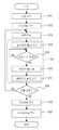
도 3은 본 발명의 하나 이상의 실시예에 따른 조형물의 제조 프로세스의 흐름도다.
도 4a 내지 4f는 본 발명의 하나 이상의 실시예에 따른 조형물 제조 시스템으로 행해진 적층 공정의 설명도다.
도 5는 본 발명의 하나 이상의 실시예에 따른 실시예 3의 조형물 제조 시스템의 구성의 설명도다.BRIEF DESCRIPTION OF THE DRAWINGS Figure 1 is an illustration of the configuration of a sculpture production system according to one or more embodiments of the present invention.
2 is an explanatory diagram of the configuration of a molding container according to one or more embodiments of the present invention.
3 is a flow diagram of a process for manufacturing a molding in accordance with one or more embodiments of the present invention.
Figures 4A-4F are illustrations of a laminating process performed with a build-in material manufacturing system in accordance with one or more embodiments of the present invention.
Fig. 5 is a diagram for explaining the configuration of a molding production system of Embodiment 3 according to one or more embodiments of the present invention. Fig.
이하, 첨부한 도면을 참조해서 본 발명의 실시예를 상세하게 설명한다. Hereinafter, embodiments of the present invention will be described in detail with reference to the accompanying drawings.
종래의 분말베드 용융결합 기술의 과제Problems of Conventional Powder Bed Melting Bonding Technology
용융로에서 제조된 금속 잉곳으로부터 가공된 조형물의 내부 채움 밀도는, 보통 99.9%이상이다. 한편, 종래의 분말베드 용융결합 기술에 의해 제조된 금속의 조형물은, 내부 채움 밀도가 최대 99.7%이므로, 금속 잉곳으로부터 가공된 조형물만큼 밀도가 높을 수 없다. 성형 금형과 같은 높은 표면품질이 요구되는 용도의 경우, 종래의 분말베드 용융결합 기술을 사용하여 만들어진 조형물은, 표면이 거칠기 때문에, 그대로 그 목적으로 사용하는 것은 어려웠다. The internal filling density of the machined workpieces from the metal ingots produced in the melting furnace is usually at least 99.9%. On the other hand, the metal mold manufactured by the conventional powder bed melt bonding technique can not have a density as high as that of the metal mold ingot because the inner fill density is at most 99.7%. In applications where a high surface quality such as a molding die is required, it is difficult to use a molding made using the conventional powder bed melt bonding technology because of its rough surface.
또한, 종래의 분말베드 용융결합 기술에 의해 제조된 금속의 조형물은, 조형물의 표면 및 내부의 조직에 구멍이나 간극을 많이 갖는다. 높은 인장강도와 굽힘 강도를 요구하는 구조물 용도로 상기 종래의 조형물을 사용하는 경우, 조형물의 표면 및 내부의 조직의 구멍들을 기점으로 한 균열의 성장이나 피로 파괴에 관한 걱정이 생긴다. In addition, the metal moldings manufactured by the conventional powder bed melt bonding technique have many holes and gaps in the surface and inside structure of the molding. When the above conventional molding is used for a structure requiring a high tensile strength and a bending strength, there is a fear of crack growth or fatigue failure starting from the holes on the surface and inside of the molding.
높은 표면품질이 요구되는 성형 금형이나 높은 강도를 필요로 하는 구조물의 용도로 사용될 때, 분말베드 용융결합 제품은, 내부 채움 밀도가 보통 99.9%이상이어도 된다. 조형물의 표면 및 내부의 조직에 많은 구멍이나 간극의 존재와 결합된, 99.7%미만의 종래의 분말베드 용융결합 기술들을 사용하여 제조된 조형물의 낮은 내부 채움 밀도는, 이러한 조형물의 폭넓은 이용에 제한이 되는 요인들 중 하나이었다. When used in a forming mold requiring high surface quality or a structure requiring high strength, the powder bed melt-bonded product may have an internal filling density of usually 99.9% or more. The low internal densities of the sculptures made using conventional powder bed melt bonding techniques of less than 99.7%, combined with the presence of many holes or gaps in the surface and inside tissue of the sculpture, are limited to the widespread use of such sculptures Was one of the factors that led to this.
실시예 1에서는, 원료 분체의 박층을 아르곤 가스 및 수소 가스의 분위기에서 플라즈마 처리하고 나서, 즉시 그 아르곤 가스 및 수소 가스의 분위기에서 박층의 고형화 영역(고형화될 영역)을 레이저 빔에 의해 가열해서 적층하고 있다. 이것은, 내부 채움 밀도가 99.9%를 상회하는 삼차원 조형물에, 종래의 기술과 비교하여 높은 빈도와 높은 재현성을 제공한다. In Example 1, the thin layer of the raw powder was subjected to plasma treatment in an atmosphere of argon gas and hydrogen gas, and then the solidified region (solidified region) of the thin layer was immediately heated by the laser beam in the atmosphere of argon gas and hydrogen gas, . This provides a high frequency and high reproducibility in comparison with the prior art in three-dimensional sculptures whose internal filling density exceeds 99.9%.
이것은, 종래의 분말베드 용융결합 기술로 관찰된 낮은 내부 채움 밀도가 원료 분체의 표면에 존재하는 부동화 피막이나 오물에 기인하고, 그것들을 플라즈마 처리가 물리적 혹은 화학적 작용으로 제거한다는 것을 제안한다. 또한, 플라즈마 처리는, 원료 분체의 표면의 표면 습윤성을 표면 에너지를 증가시켜서 향상하고, 이것은 용융시에 기포가 혼입되는 것을 방지함으로써 기여할 수도 있다. This suggests that the low internal fill densities observed with conventional powder bed melt bonding techniques are due to passivating coatings or dirt present on the surface of the raw powder and remove them by physical or chemical action of the plasma treatment. In addition, the plasma treatment improves the surface wettability of the surface of the raw material powder by increasing the surface energy, which may contribute to prevention of incorporation of bubbles during melting.
실시예 1Example 1
조형물 제조 시스템Sculpture manufacturing system
도 1은 실시예 1에 따른 조형물 제조 시스템의 구성의 설명도다. 도 2는 조형 용기의 구성의 설명도다. 도 1에 도시한 바와 같이, 조형물 제조 시스템(100)은, 분말베드 용융결합 기술을 사용하는 것으로, 소위 3D프린터다. 용기(101)는, 스테인리스강으로 구성되고, 외기가 내측공간에 들어가는 가는 것을 막을 수 있다. 용기(101)에는, 검지부의 일례인 진공계(208)가 접속되어 있다. 진공계(208)는, 상기 용기(101)내의 압력을 검지한다.
Fig. 1 is an explanatory diagram of a configuration of a molding production system according to
감압부의 일례인 배기기구(103)는, 용기(101)내를 감압가능하다. 배기기구(103)는, 용기(101)내의 분위기중의 주로 산소 양을 감소시키기 위해서, 용기(101)로부터 배기한다. 배기기구(103)는, 드라이 펌프와 터보 분자 펌프의 직렬접속이고, 용기(101)를 예를 들면 1×10⁻⁴Pa의 진공도까지 감압할 수 있다.The
또한, 배기기구(103)는, 용기(101)와의 접속부에 개구 크기를 조정 가능한 개구(orifice)조정밸브를 가진다. 제어부(200)는, 후술하는 가스 공급 기구(102)를 작동시켜 용기(101)에 기체를 공급하고 진공계(208)의 출력에 따라 이 개구조정밸브를 조정함으로써, 용기(101)내의 분위기와 진공도를 제어한다.
The
공급부(feeder)의 일례인 가스 공급 기구(102)는, 불활성 가스의 일례인 아르곤 가스와, 수소 가스를 용기(101)내에 공급한다. 가스 공급 기구(102)는, 아르곤 가스와 수소 가스의 혼합물을 임의의 혼합 비율로 용기(101)내에 공급가능하다. 가스 공급 기구는, 아르곤 가스와 수소 가스를 따로따로 공급하도록 2개가 따로따로 있어도 된다.
The
도 2에 도시한 바와 같이, 분체용기의 일례인 조형 용기(107)는, 조형실(109)의 내측에 수직으로 이동 가능한 적층 플랫폼(112)을 갖는다. 하강 기구(111)는, 층 104의 두께에 대응시킨 임의의 피치로 적층 플랫폼(112)을 단계적으로 하강시킬 수 있다. 조형실(109)에는, 각 층 104의 플라즈마 처리의 결과로서, 처리된 층들 104'가 적층된다.
As shown in Fig. 2, the
조형실(109)의 벽에는, 히터의 일례인, 층 104를 가열 가능한 매립 저항 히터(137)가 있다. 상기 적층 플랫폼(112)의 상면에는, 온도 센서(209)가 있다. 제어부(200)는, 온도 센서(209)의 출력에 따라서 상기 저항 히터(137)에 전류의 흐름을 온 및 오프하여, 층 104를 일정 온도로 유지한다.
On the wall of the
형성부의 일례인 층 형성 기구(105)는, 용기(101)내에 위치된 조형 용기(107)의 조형실(109)에 원료 분체의 층 104를 형성한다. 층 형성 기구(105)에 의해 형성된 원료 분체의 층은 두께가 5μm이상 200μm이하이며 대단히 얇다. 따라서, 여기에서는 원료 분체의 층 104를 박층이라고 한다.
The
박층 형성 기구(105)는, 가이드(132)에 의해 안내된 것처럼, 조형 용기(107)의 상면을 따라 화살표 R105의 방향으로 이동하는 이동부(133)를 갖는다. 원료 분체(135)는, 원료실(130)에 축적되고, 바닥판(134)의 상승에 의해 조형 용기(107)의 상면보다도 높은 위치로 올려진다. 박층 형성 기구(105)는, 금속 롤러(131)를 조형 용기(107)의 상면에 대하여 카운터 방향으로 회전시키면서 조형 용기(107)의 상면에 드러난 원료 분체를 잘라내어서, 적층 플랫폼(112)의 상면에 일정 두께로 조직의 밀도가 높은 원료 분체(135)의 박층 104를 형성한다. 또한, 박층 형성 기구(105)는, 조형실(109)에 형성한 박층 104를 플라즈마 처리한 처리된 박층(들) 104' 위에, 새로운 원료 분체의 박층 104를 형성한다.
The thin
조형 용기Molding container
원료 분체의 내부가 금속인 경우도, 원료 분체는, 그 표면이 산화막등의 부동화 피막으로 덮어져 있기 때문에, 통상은 원료 분체 입자간의 도전성이 낮다. 이 때문에, 플라즈마 방전에의 노출에 의해 원료 분체의 플라즈마 처리가 박층 104와 대향하는 평판 전극에 AC전압을 인가하는 것을 필요로 한다고 일반적으로 믿고 있었다. 그러나, 박층 104보다 위에 놓인 평판전극은, 박층 104에 레이저 빔을 조사하는 광로를 차단하고, 조형 용기(107)의 상면을 따라 이동하는 박층 형성 기구(105)에 충돌한다. 이 때문에, 박층 104보다 위에 놓인 평판전극이, 그 평판전극을 박층 104 위로부터 물리적으로 퇴피시키는 퇴피 기구를 필요로 한다고 일반적으로 믿고 있었다.
Even when the inside of the raw powder is a metal, since the surface of the raw powder is covered with a passivation film such as an oxide film, the conductivity between the raw powder particles is usually low. For this reason, it was generally believed that plasma treatment of the raw powder by exposure to the plasma discharge required applying an AC voltage to the plate electrode opposite to the
그러나, 조형물 제조 시스템(100)에서는, 후술하는 것처럼 수십 mm의 두께의 조형물을 조형할 경우라도 박층 104의 형성과 플라즈마 처리를 수백 회 내지 수천 회나 반복한다. 이 때문에, 박층 104를 형성할 때마다 평판전극을 박층 104보다 위로부터 퇴피시키면, 시간적인 손실이 크다. 평판전극의 퇴피에 관련된 오염물질의 낙하나 퇴피 기구의 고장도 문제가 된다.
However, in the molding
본 발명자는, 박층 104보다 위에 평판전극을 사용하지 않는 조형 용기(107)에 형성된 박층 104를 플라즈마 처리하기 위한 플라즈마 방전 방식을 개발했다. 본 발명자는, 용기(101)나 조형 용기(107)의 지지 구조등의 부품에 대해 전기적으로 뜨게 한 상태로, 박층 104에 AC전압을 인가하는 것으로, 박층 104의 표면 영역에 균일한 플라즈마 아크가 발생하는 것을 우선 발견했다. 본 발명자는, 용기(101)가 접지되고, 조형 용기(107)가 그 용기(101)로부터 전기적으로 절연되고, 박층 104에 접촉시킨 전극(108)에 AC전압이 인가되는, 플라즈마 방전 방식을 개발했다. 이러한 플라즈마 방전 방식은, 박층 104자체가 방전 전극이 되기 때문에, 박층 104에 대향시킨 평판전극 없이 행해질 수 있다.
The present inventor has developed a plasma discharge method for plasma processing a
도 1에 도시한 바와 같이, 조형 용기(107)는, 접지되고 상기 용기(101)로부터 전기적으로 절연된, 용기(101)내에 위치되어 있다. 조형 용기(107) 및 적층 플랫폼(112)은, 그들 표면에서의 플라즈마 형성을 회피하기 위해서, 절연 재료로 이루어진다. 조형 용기(107)의 박층 104에 접촉하는 면은 절연성이다. 원료 분체의 박층 104에 전원(113)으로부터 나오는 전압을 공급하는 전극(108)(전원부)은, 그 표면에 플라즈마 형성을 회피하기 위해서, 절연성 커버(108a)를 갖는다.
As shown in Fig. 1, the
실시예 1에서는, 절연성의 조형 용기(107)의 조형실(109)내에 형성된 박층 104는, 용기(101)로부터 전기적으로 절연되고, 상기 전극(108)은 박층 104에 AC전압을 인가하는데 사용된다. 박층 104를 보유하는 조형 용기(107)를 용기(101)로부터 전기적으로 절연한 상태로, 박층 104에 접촉하는 전극(108)에 AC전압을 인가한다. 이러한 구성에 의해, 실시예 1에서는, 평판전극이나 어떠한 동일한 부품도 필요 없이, 박층 104의 표면 전체에 균일한 플라즈마를 발생하고, 박층 104의 원료 분체의 균일한 플라즈마 처리를 신속하게 행하는 것이 가능하다.
The
플라즈마 처리Plasma treatment
도 1에 도시한 바와 같이, 조형물 제조 시스템(100)은, 조형 용기(107)에 형성된 원료 분체의 박층 104에 AC전압을 인가해서 박층 104의 인접공간에 플라즈마를 발생시킨다. 조형물 제조 시스템(100)은, 최초의 층으로서 적층 플랫폼(112) 위에 형성된 박층 104의 플라즈마 처리를 행하고, 2층 이후의 층들로서 처리된 박층 104' 위에 형성된 박층 104의 플라즈마 처리를 실시한다.
As shown in FIG. 1, the
전원부의 일례인 전원(113) 및 전극(108)은, 박층 104에 AC전압을 인가한다. 전원(113)은, 전극(108)을 통해서 원료 분체의 박층 104에 AC전압을 인가한다. 도 2에 도시한 바와 같이, 전극(108)은, 조형 용기(107)내에서 박층 104 또는 처리된 박층 104'에 접촉하고 있다. 전원(113)은, DC전압 또는, DC전압을 중첩한 AC전압을 출력하는 것도 가능하다. 다수의 DC전압은, -500V∼+500V의 범위로부터 선택될 수 있다. 이 AC전압의 경우, 0∼2000V의 범위와 10kHz∼500kHz의 범위로부터 각각 다수의 진폭 및 다수의 주파수가 선택될 수 있다.
The
제어부(200)는, 용기(101)내에 수소 가스 및/또는 불활성 가스를 공급하면서, 진공도를 10Pa이상 10kPa미만으로 유지한 상태로, 전원(113)을 작동시킨다. 이것은, 박층 104의 인접공간에 국소화된 플라즈마의 형성을 확보하고, 박층 104의 원료 분체의 플라즈마에의 효율적인 노출과 그 원료 분체의 신속한 플라즈마 처리를 제공한다.
The
플라즈마 처리 동안에, 불활성 가스의 일례인 수소 이온 및/또는 아르곤의 이온과 유리 전자를 포함하는 플라즈마중에 원료 분체가 보유된다. 아르곤 이온 및 유리 전자를 사용한 플라즈마 처리는, 소위 스퍼터 클리닝 효과를 제공하기 위한 것이다. 아르곤 이온은, 원료 분체의 입자표면에 충돌하고, 부착하는 산화막 또는 이물질을 완전히 제거한다. 또한, 유리 전자는 원료 분체의 입자표면에 충돌하고, 고온으로 가열된 상기 표면들에 상기 부착하는 산화막 또는 이물질을 증발시킨다. 이 결과, 이물질에 덮어져 있었던 원료 분체의 재료가 노출된다. During the plasma treatment, the raw powder is retained in a plasma containing ions of hydrogen ions and / or argon and free electrons, which are examples of inert gases. The plasma treatment using argon ions and free electrons is intended to provide a so-called sputter cleaning effect. The argon ions impinge on the particle surface of the raw powder, and completely remove the adhering oxide film or foreign matter. Further, the glass particles impinge on the particle surface of the raw material powder and evaporate the oxide film or foreign matter adhering to the surfaces heated to a high temperature. As a result, the material of the raw powder covered by the foreign substance is exposed.
한편, 수소 이온을 이용하는 플라즈마 처리는, 소위 화학 환원에 의해, 주로 원료 분체의 입자표면의 부동화 피막을 제거하는데 목적이 있다. 이것은, 탈산화된 원료 분체와 높게 결정화 가능한(crystallizable) 입자표면을 제공하여, 원료 분체의 입자들이 비교적 낮은 온도에서도 융합하고, 입자들이 결정 격자의 불규칙이 적은 결정들을 형성하는 것을 도와준다. On the other hand, the plasma treatment using hydrogen ions has a purpose of mainly removing the passivated coating on the particle surface of the raw material powder by so-called chemical reduction. This provides for deoxidized raw powder and highly crystallizable particle surfaces to help the particles of the raw powder to fuse at relatively low temperatures and to help the particles form less irregular crystals of the crystal lattice.
도 2에 도시한 바와 같이, 플라즈마 처리중, 상기 저항 히터(137)가 통전되어 적층 플랫폼(112) 위에 원료 분체의 박층 104를 보조로 가열함으로써, 플라즈마 처리를 보다 효율화할 수도 있다. 레이저 빔LB는, 보조 열원으로서 상기 저항 히터(137) 대신에 혹은 상기 저항 히터(137)와 조합하여, 사용되어도 좋다. 보다 구체적으로는, 레이저 빔LB를 감소된 강도나 보다 넓은 스폿 면적에 걸쳐 주사하여서 박층 104을 용융하지 않고 가열할 수 있다.
As shown in FIG. 2, during the plasma processing, the
레이저 열성형 처리Laser thermoforming treatment
도 1에 도시한 바와 같이, 주사 가열 기구(106)는, 집광 렌즈와 콜리메이터 렌즈 등의 광학소자를 선택사항으로 구비한다. 광원(110)은, 출력 500W의 YAG레이저 발진기다. 주사 가열 기구(106)는, 광원(110)에서 발생시킨 레이저 빔을 갈바노 미러106m를 사용하여 주사함에 의해, 처리된 박층 104'의 고형화 영역을, 레이저 빔LB의 빔 스폿으로 가열한다.
As shown in Fig. 1, the
3D CAD소프트웨어에 의해 발생된 삼차원 조형물의 설계 데이터는, 2D CAM소프트웨어상에서 박층 104의 두께에 대응하는 간격으로 슬라이스한 복수의 고형화 영역의 이차원 슬라이스 데이터로 변환된다. 주사 가열 기구(106)의 NC프로그램은, 특정한 고형화 영역의 이차원 데이터를, 동시 수평 2축방향의 상대 이동을 제어하는 각 박층 104의 고형화 영역에 대한 주사 프로그램으로 변환한다. 제어부(200)는, 고형화 영역마다의 주사 프로그램을 따라서 주사 가열 기구(106)를 제어하여, 레이저 빔LB로 조형 용기(107)의 평면상의 소정의 경로를 주사시킨다.
The design data of the three-dimensional sculpture generated by the 3D CAD software is converted into two-dimensional slice data of a plurality of solidification areas sliced at intervals corresponding to the thickness of the
빔 방출기의 일례인 주사 가열 기구(106)는, 상기 처리된 박층 104' 또는 플라즈마 처리된 박층 104에, 에너지 빔의 일례인 레이저 빔LB를 조사한다. 주사 가열 기구(106)로부터 방출된 레이저 빔에 의해, 조형 용기(107)의 조형실(109)의 상부면을 형성하는 상기 처리된 박층 104'를 가열한다. 그 레이저 빔은, 상기 처리된 박층 104'를 용융하여 거의 순시에 보다 낮은 고체조직과 고형화시킨다. 이에 따라, 조형실(109)의 상부면으로서 상기 처리된 박층 104'의 영역을 용융해서 고형화한다. 이 레이저 열성형 처리 공정 동안에, 플라즈마 처리와 상기 저항 히터(137)의 통전은, 상기 처리된 박층 104'의 온도를 높게 유지하도록 계속되어도 된다. 처리된 박층 104'의 온도를 높게 유지하는 것으로, 레이저 열성형 처리를 더 효율적으로 하고, 그러므로, 레이저 빔의 출력이 낮을 때에도 고속의 레이저 열성형 처리를 가능하게 하고, 덧붙여, 처리된 박층 104'가 더 일관되게 용융되는 것을 확보함으로써 결과적인 조형물(301)을 더 균일한 조직으로 한다.
The
또한, 이 레이저 열성형 처리의 공정에서 레이저 빔의 가열은, 상기 처리된 박층 104'의 원료 분체의 플라즈마 처리를 촉진시키는데 사용될 수 있다. 이 때문에, 상기 플라즈마 처리의 공정에서 원료 분체의 플라즈마 처리는, 100% 완료될 필요는 없다. 예를 들면, 플라즈마 처리의 공정에서 거의 80% 진행에서 플라즈마 처리를 중지하고, 원료 분체를 용융하기 전에 레이저 열성형 처리의 공정에서 목표 레벨의 100%를 달성하는 것이 가능하다. 이것은, 플라즈마 처리에 요구되는 시간을 단축하여서 조형물(301)의 제조를 촉진한다.
In addition, the heating of the laser beam in the process of the laser thermoforming process can be used to promote the plasma treatment of the raw powder of the treated
조형물의 제조 프로세스Manufacturing process of sculpture
도 3은 조형물의 제조 프로세스의 흐름도다. 도 4a 내지 4f는 조형물 제조 시스템에서 행한 적층 공정의 설명도다. 도 1에 도시한 바와 같이, 제어부(200)는, CPU(205), RAM(206) 및 ROM(207)을 가진다. ROM(207)으로부터 호출한 프로세스의 제어 프로그램을 RAM(206)에 기억함으로써, CPU(205)는, 조형물 제조 시스템(100)의 프로세스 컨트롤러로서 기능한다. 유저는, 상기 시스템에 조작부(201)를 통해서 상기 프로세스 시작의 지령한다.
3 is a flow chart of a manufacturing process of a molding. 4A to 4F are explanatory views of the lamination process performed in the molding production system. 1, the
도 3에 도시한 바와 같이, 제어부(200)는, 프로세스 시작 지령에 응답하여, 배기기구(103)를 작동시켜서 용기(101)내를 배기한다(S11). 용기(101)내의 압력이 1×10⁻²Pa에 도달한 후, 가스 공급 기구(102)는, 가스 공급을 시작하고, 용기(101)내의 압력을 대기압 미만의 프로세스 압력으로 조정하도록 작동된다(S12). 스텝S11 및 S12로 구성되는 분위기 생성 공정에서, 도 1에 도시한 바와 같이, 용기(101)를 제1의 압력으로 감압하고 나서, 용기(101)내에 아르곤 가스와 수소 가스를 공급하여, 용기(101)내에 제1의 압력보다도 높은 대기압미만의 제2의 압력의 분위기를 생성한다.As shown in Fig. 3, the
도 3에 도시한 바와 같이, 제어부(200)는, 용기(101)내의 압력이 제2의 압력(예를 들면, 5kPa)에 도달한 후, 박층 형성 기구(105)를 작동시켜 원료 분체의 박층 104를 형성한다(S13). 도 4a에 도시한 바와 같이, 하강 공정에서는, 하강 기구(111)를 작동시켜 적층 플랫폼(112)을 하강시킴으로써, 조형 용기(107)의 내측에 박층 104의 형성 공간을 형성한다. 도 4b에 도시한 바와 같이, 이 형성 공정에서 또는 이 스텝S13에서는, 박층 형성 기구(105)를 작동시켜 적층 플랫폼(112) 위에 원료 분체의 박층 104를 형성한다.
3, after the pressure in the
도 3에 도시한 바와 같이, 제어부(200)는, 전원(113)을 작동시켜 플라즈마 발생을 시작해(S14), 박층 104의 플라즈마 처리를 지정 시간이 경과할 때까지 계속한다(S15의 NO). 도 4c에 도시한 바와 같이, 이 스텝S14 및 S15로 구성된 이 플라즈마 처리 공정에서는, 적층 플랫폼(112) 위에 원료 분체의 박층 104를 플라즈마 처리한다. 플라즈마 처리 공정에서는, 아르곤 가스 및 수소 가스를 포함하는 저산소 분위기에서, 전원(113)에 의해 박층 104에 AC전압을 인가해서 플라즈마를 발생시킨다. 플라즈마 처리 공정은, 용기(101)내에 생성된 대기압 미만(바람직하게는 10Pa이상 10kPa미만)의 압력의 분위기에서 행해진다. 플라즈마 처리 공정은, 박층 104를 상기 저항 히터(137)를 사용하여 가열해서 박층 104의 온도를 일정하게 유지한 상태로 실행된다.
As shown in Fig. 3, the
도 3에 도시한 바와 같이, 제어부(200)는, 박층 104의 플라즈마 처리PN이 종료한 후(S15의 YES), 주사 가열 기구(106) 및 광원(110)을 제어하여, 처리된 박층 104'의 레이저 열성형 처리를 행한다(S16). 빔 성형 공정에서 또는 스텝S16에서는, 주사 가열 기구(106) 및 광원(110)을 작동시켜 레이저 열성형 처리를 행하여, 도 4d에 도시한 바와 같이 적층 플랫폼(112) 위의 처리된 박층 104'를 용융해 고형화한다. 빔 성형 공정에서는, 처리된 박층 104'의 고형화 영역에 에너지 빔을 조사해서 고형화한다. 빔 성형 공정은, 아르곤 가스 및 수소 가스를 포함하는 저산소 분위기에서, 처리된 박층 104'에 AC전압을 인가해서 플라즈마를 발생시키면서 행해진다.
3, the
도 3에 도시한 바와 같이, 제어부(200)는, 처리된 박층 104'의 1층분의 레이저 열성형 처리의 종료한 후(S16), 전원(113)을 정지시켜 상기 처리된 박층 104'에 있어서의 플라즈마 발생도 정지한다(S17). 제어부(200)는, 조형물(301)의 완료를 위해 적층 횟수(적층된 층의 수)에 도달할 때까지 (S18의 NO), 박층 형성(S13), 플라즈마 처리(S14, S15), 레이저 열성형 처리(S16), 및 플라즈마 발생 정지(S17)를 반복한다. 2회째의 하강 공정에서는, 하강 기구(111)를 작동시켜 적층 플랫폼(112)을 하강시킴으로써, 도 4e에 도시한 바와 같이, 고형화되지 않은 부분을 포함하는 전체 처리된 박층 104' 위에 새로운 원료 분체의 박층 104의 형성 공간을 형성한다. 2회째의 형성 공정에서는, 박층 형성 기구(105)를 작동시켜서, 도 4f에 도시한 바와 같이 다음 원료 분체의 박층 104를 형성한다. 조형 용기(107)의 저면상의 처리된 박층 104' 위에 새로운 박층 104를 형성한다.
3, the
도 3에 도시한 바와 같이, 조형물 제조 시스템(100)은, 박층 형성, 플라즈마 처리, 및 레이저 열성형 처리를 반복하는 것에 의해, 처리된 박층 104'의 고형화 영역의 적층체로서 삼차원의 조형물(301)을 조형한다. 제어부(200)는, 조형물(301)의 완료를 위한 적층 횟수에 도달한 후(S18의 YES), 가스공급을 정지해(S19), 용기(101)내에 외기를 도입한다(S20). 그리고, 제어부(200)는, 표시부(202)를 거쳐 조형물(성형품)(301)이 제거될 수 있는 것을 유저에게 말한다.
As shown in Fig. 3, the
다른 재료로부터 조형물을 제조Manufacture of sculptures from other materials
이 조형물 제조 시스템(100)을 사용하여, 이하의 예 1, 2 및 3과 같이 원료 분체의 다른 재료와, 다른 플라즈마 처리 조건, 및 다른 레이저 열성형 처리 조건으로 일부의 조형물(301)을 제조한다. 결과적인 조형물(301)은 밀도에 대해 확인되었다.
By using the
예 1Example 1
예 1에서는, 이하의 조건으로, 스테인리스강의 원료 분체에 대해 플라즈마 처리/레이저 열성형 처리 되었다. In Example 1, the raw powder of stainless steel was subjected to plasma treatment / laser thermoforming under the following conditions.
플라즈마 처리 조건Plasma treatment conditions
용기(101)내의 압력: 6.66kPa Pressure in the vessel 101: 6.66 kPa
공급 가스: 아르곤 가스 Feed gas: argon gas
원료 분체: 물 분사법에 의한 입경 7μm의 SUS613 원료 분체 Raw material powder: SUS613 raw material powder having a particle diameter of 7 탆 by water spraying method
박층 104의 두께: 20μm Thickness of thin layer 104: 20 m
인가 전압: AC전압 1kV, 주파수 100kHz Applied voltage: AC voltage 1kV, frequency 100kHz
처리 시간: 1분 Processing time: 1 minute
레이저 열성형 처리 조건Laser thermoforming treatment conditions
용융 영역: 박층 104 위의 폭 25mm 및 길이 25mm를 측정하는 정방형 영역
Melting area: square area measuring 25 mm width and 25 mm length on
적층 횟수: 5000 Number of laminations: 5000
적층 높이: 100mm Lamination height: 100mm
아르키메데스법에 의해 계측한 것과 같은 예 1에 있어서 얻어진 조형물(301)의 내부 채움 밀도는, 99.9%이상이었다. 이에 따라, 예 1에서 사용된 조건이, 통상의 분말베드 용융결합법으로 제조된 스테인리스강 조형물보다도 밀도가 높은 조형물(301)을 제공한 것이 확인되었다.
The internal filling density of the
예 2Example 2
예 2에서는, 이하의 조건으로, 티타늄 원료 분체에 대해 플라즈마 처리/레이저 열성형 처리 되었다. In Example 2, the titanium raw material powder was subjected to plasma treatment / laser thermoforming under the following conditions.
플라즈마 처리 조건Plasma treatment conditions
용기(101)내의 압력: 13.3Pa Pressure in the vessel 101: 13.3 Pa
공급 가스: 아르곤 가스50% +수소 가스50%의 혼합 가스(분자수비%) Feed gas: mixed gas of 50% of argon gas + 50% of hydrogen gas (molecular weight ratio%)
원료 분체: 물 분사법에 의한 입경 50μm의 Ti원료 분체 Raw material powder: Ti raw material powder having particle diameter of 50 탆 by water spraying method
박층 104의 두께: 100μm Thickness of thin layer 104: 100 m
인가 전압: AC전압 20kV, 주파수 7kHz Applied voltage: AC voltage 20kV, frequency 7kHz
처리 시간: 3분 Processing time: 3 minutes
분체용기(107)는 상기 저항 히터(137)에 의해 사전 가열되었고, 박층 104 및 조형물(301)을 400℃로 유지하여 부동화 피막의 수소 환원을 촉진하도록 제어되었다.
The
레이저 열성형 처리 조건Laser thermoforming treatment conditions
용융 영역: 박층 104 위의 폭 25mm 및 길이 25mm를 측정하는 정방형 영역
Melting area: square area measuring 25 mm width and 25 mm length on
적층 횟수: 500 Number of laminations: 500
적층 높이: 50mm Stack height: 50mm
아르키메데스법에 의해 계측한 것과 같은 예 2에 있어서 얻어진 조형물(301)의 내부 채움 밀도는, 99.9%이상이었다. 이에 따라, 예 2에서 사용된 조건이, 통상의 분말베드 용융결합법으로 제조된 티타늄 조형물보다도 밀도가 높은 조형물(301)을 제공한 것이 확인되었다.
The internal filling density of the
예 3Example 3
예 3에서는, 이하의 조건으로, 알루미늄 원료 분체에 대해 플라즈마 처리/레이저 열성형 처리 되었다. In Example 3, the aluminum raw material powder was subjected to plasma treatment / laser thermoforming under the following conditions.
플라즈마 처리 조건Plasma treatment conditions
용기(101)내의 압력: 1.0kPa Pressure in the vessel 101: 1.0 kPa
공급 가스: 수소 가스100%
Supply gas:
원료 분체: 물 분사법에 의한 입경 80μm의 Al 원료 분체 Raw material powder: Al raw material powder having a particle diameter of 80 탆 by water spraying method
박층 104의 두께: 100μm Thickness of thin layer 104: 100 m
인가 전압: AC전압 1.5kV, 주파수 100kHz Applied voltage: AC voltage 1.5kV, frequency 100kHz
처리 시간: 3분 Processing time: 3 minutes
분체용기(107)는 상기 저항 히터(137)에 의해 사전 가열되었고, 박층 104 및 조형물(301)을 400℃로 유지하여 부동화 피막의 수소 환원을 촉진하도록 제어되었다.
The
레이저 열성형 처리 조건Laser thermoforming treatment conditions
용융 영역: 박층 104 위의 폭 5mm 및 길이 5mm를 측정하는 정방형 영역
Melting area: square area measuring 5 mm width and 5 mm length on
적층 횟수: 50 Number of laminations: 50
적층 높이: 5mm Stack height: 5mm
아르키메데스법에 의해 계측한 것과 같은 예 3에 있어서 얻어진 조형물(301)의 내부 채움 밀도는, 99.9%이상이었다. 열 용융으로 측정된 것과 같은 조형물 산소 레벨은 0.1%미만이었다. 이에 따라, 예 3에서 사용된 조건이, 통상의 분말베드 용융결합법으로 제조된 알루미늄 조형물보다도 밀도가 높고 순수한 조형물(301)을 제공한 것이 확인되었다.
The inner filling density of the
실시예 1의 이점Advantages of
실시예 1에서는, 저산소 분위기에서 박층 104의 원료 분체를 플라즈마 처리하므로, 부동화 피막이 형성된 원료 분체의 산화를 방지한다. 또한, 박층 104의 원료 분체를 플라즈마 처리하는 분위기는 아르곤을 함유한다. 아르곤 이온과 전자가 원료 분체의 표면에 충돌하고 부착한 이물질을 제거 및 가열해서, 결정성이 높은 표면을 남긴다. 또한, 박층 104의 원료 분체의 플라즈마 처리를 위한 분위기는 수소를 함유하고, 이것은, 부동화 피막이 제거된 원료 분체의 표면에 존재하는 산화막의 수소 환원을 촉진한다. 이렇게 하여, 본 실시예는 분말베드 용융결합에 의해 내부 채움 밀도의 문제점을 해소하고, 예를 들면 내부 채움 밀도 99.9%이상의 고밀도, 우수한 표면 특성 및 고강도의 조형물의 조형을 가능하게 한다.
In Example 1, the raw powder of the
실시예 1에서는, 박층 104에 AC전압을 인가해서 상기 분위기에서 상기 가스와 접촉하는 박층 104의 표면에서 플라즈마를 발생시킨다. 전극(108)이 조형 용기(107)내에서 박층 104 또는 처리된 박층 104'에 접촉해서 AC전압을 인가할 때, 박층 104가 방전 전극으로서 작용한다. 박층 104보다 위에 AC전압을 인가하기 위한 전극이 필요하지 않다. 박층 104보다 위에 평판전극이나 코일 등의 방전을 지원하는 부품이 필요하지 않다. 박층 104에 대한 레이저 빔LB의 조사나 박층 형성 기구(105)에 의한 박층 104의 형성을, 방해하지 않는 박층 104보다 위에 공간이 많이 있다.
In
실시예 1에서는, 박층 104에 대해 AC전압이 인가된 조형 용기(107)는 절연 재료로 구성된다. 이것은, 조형 용기(107)상에서 플라즈마를 발생시키지 않는 분위기에서 박층 104의 상기 가스와 접촉하는 표면에 국소화된 플라즈마의 형성을 확보한다. 박층 104의 이 표면에의 국소화된 플라즈마의 형성은, 박층 104의 전체 표면에 걸쳐서 아주 균일한 플라즈마 처리에 이어진다. 플라즈마중의 아르곤 이온 및 수소 이온이 박층 104에 효율적으로 충돌하고, 원료 분체 표면을 덮는 재료, 이를테면 산화물, 부동화 피막 및 오물을 고속으로 제거한다. 따라서, 본 실시예에서의 플라즈마 처리는, 고속이고 아주 효율적이다.
In
실시예 1에서는, 상기 형성된 원료 분체의 박층 104에 대해 직접 플라즈마 처리된다. 그러므로, 플라즈마 발생 시간을 연장하여서 상기 처리된 박층 104'는 임의의 원하는 처리 레벨로 얻어질 수 있다. 플라즈마 발생 시간을 조정함으로써, 상기 처리된 박층 104'의 플라즈마 처리 레벨을 정밀하게 제어할 수 있다.
In Example 1, the
실시예 1에서는, 용기(101)내에 생성된 대기압미만의 분위기에서 플라즈마 처리를 실행한다. 그러므로, 대기압이상의 분위기에서 플라즈마 처리를 실행할 경우와 비교하여, 플라즈마 상태를 안정하게 유지할 수 있다.
In the first embodiment, the plasma treatment is performed in the atmosphere below the atmospheric pressure generated in the
실시예 1에서는, 용기(101)내에 생성된 10Pa이상 10kPa미만의 압력의 분위기에서 플라즈마 처리를 실행한다. 그러므로, 원료 분체의 플라즈마 처리는, 낮은 진공도에서 보다 빠르다.
In the first embodiment, the plasma treatment is performed in an atmosphere having a pressure of 10 Pa or more and less than 10 kPa produced in the
실시예 1에서는, 용기(101)를 제1의 압력으로 감압한 후에, 용기(101)내에 불활성 원소를 공급해서 제1의 압력보다도 높은 대기압미만의 제2의 압력의 분위기를 생성한다. 이 때문에, 플라즈마를 발생시키는 분위기로부터 많은 산소를 제거하고, 이것은 원료 분체에 함유된 산소, 유기물, 수분 등의 오염물에 의해 플라즈마 처리중의 분위기가 오염되는 것을 막는다.
In
실시예 1에서는, 용기(101)로부터 전기적으로 절연된 조형 용기(107)에 박층 104를 형성해서 플라즈마 처리를 실행한다. 따라서, 박층 104에 AC전압을 인가했을 때의 전류누설이 적고, 상기 분위기에서 가스와 접촉하는 박층 104의 표면에 결과적인 플라즈마의 국소화가 효율적인 플라즈마 처리로 이어진다.
In the first embodiment, the
실시예 1에서는, 박층 104를 히터를 사용하여 가열해서 박층 104의 온도를 일정하게 유지한 상태로 플라즈마 처리를 실행한다. 이에 따라, 원료 분체의 온도가 상승해서 플라즈마 처리가 빨라지고, 적층된 제1층으로부터 최종층까지 원료 분체의 보다 일관된 처리 레벨을 확보하게 된다.
In
실시예 1에서는, 원료 분체가, 물 분사법에 의해 형성된 금속입자이다. 이 때문에, 가스 분사법에 의해 형성된 금속입자를 사용하는 경우보다도 원료 비용이 낮다. 일반적으로, 물 분사법에 의해 형성된 금속입자는 두꺼운 부동화 피막으로 덮어져 있다. 그렇지만, 본 실시예에서는, 플라즈마 상태의 수소 이온과의 반응으로 상기 부동화 피막을 제거하여, 원료 분체의 플라즈마 처리를 효율적으로 행한다. In Example 1, the raw material powder is a metal particle formed by a water spraying method. Therefore, the raw material cost is lower than that in the case of using the metal particles formed by the gas spraying method. Generally, metal particles formed by water spraying are covered with a thick passivation film. However, in this embodiment, the passivation film is removed by reaction with the hydrogen ions in the plasma state, and the plasma treatment of the raw powder is performed efficiently.
실시예 1에서는, 처리된 박층 104'의 고형화 영역에 레이저 빔LB을 조사해서 고형화한다. 용기(101)의 내측이 고진공도가 아닐 때에도 전자 빔과 달리 레이저 빔은 감쇠나 산란되지 않는다. 이 때문에, 10Pa이상 10kPa미만의 낮은 진공도에서도 처리된 박층 104'를 효율적으로 가열할 수 있다.
In
실시예 1에서는, 플라즈마 처리된 박층 104'를 외기에 노출시키지 않고 즉시 레이저 열성형 처리로 진행한다. 레이저 열성형 처리 동안에 플라즈마 처리는 계속한다. 이 때문에, 원료 분체의 표면으로부터 산화물과 이물질 대부분을 레이저 열성형 처리시에 제거하여, 효율적인 분말베드 용융결합을 가능하게 한다.
In
조형물의 결정 구조Crystal structure of sculpture
실시예 1에서는, 소위 존(zone) 용융법에 의해 단결정을 성장시켰을 경우와 같이, 하층의 중심 결정에 위쪽으로 반복해서 결정을 성장하여, 조형물(301)을 형성한다. 이 때문에, 원료 분체의 박층 104의 플라즈마 처리와 이후의 처리된 박층 104'을 레이저 빔LB에 의한 용융 및 고형화를 통해 각각 형성된 고체층들로 구성된 조형물(301)은, 제1층 측의 면으로부터 최종층 측의 면에의 방향으로 결정이 병렬로 성장된 결정 조직을 가진다. 또한, 조형물(301)은, 이 조형물의 표면뿐만 아니라 내부까지 산화물과 이물질이 없다.
In Example 1, crystal is grown repeatedly upward in the center crystal of the lower layer, as in the case of growing a single crystal by the so-called zone melting method, to form a
상술한 것처럼, 실시예 1에서는, 조형물(301)의 아르키메데스법으로 측정한 조형물(301)의 내부 채움 밀도가 99.9%이상이다. 이러한 높은 내부 채움 밀도까지 금속 분체를 고형화시키는 기술은 지금까지 존재하지 않았다. 내부 채움 밀도가 높은 하나의 이유는, 플라즈마 처리에 의해, 원료 분체로부터 산화물과 이물질을 아주 효율적으로 제거하기 때문이다. 다른 이유는, 용기(101)내의 보통의 진공도에 의해 플라즈마 처리에 충분한 양의 아르곤 이온을 확보할 수 있기 때문이다. 예를 들면, 마무리된 조형물(301)을 플라즈마로 처리하는 것은, 상기 플라즈마에서의 아르곤 이온이 조형물(301) 내부에 도달하지 않고 조형물(301)의 표면에만 충돌하기 때문에 내부에 많은 양의 산화물과 이물질을 남길 것이다. 또한, 각 박층의 플라즈마 처리는, 불충분하다면, 조형물(301)의 내부에 산화물과 이물질을 남길 것이다. 실시예 1에서는, 특정한 플라즈마 분위기에서 각 박층을 플라즈마로 처리함으로써, 박층의 표면뿐만 아니라 박층 내부까지 플라즈마 처리하는 것을 보장한다. 그 결과의 조형물(301)은 내부도 산화물과 이물질에 관련된 간극이 적다.
As described above, in
실시예 2Example 2
실시예 1의 예들은, 합금(스테인리스강) 및 순금속(티타늄)의 조형물을 제조하는 예이었다. 실시예 2에서는, 도 1에 나타낸 조형물 제조 시스템(100)을 사용하여, 질화합금(스테인리스강) 및 탄화 금속(실리콘)의 조형물을 제조하는 예들을 설명한다.
Examples of Example 1 were an example of manufacturing a molding of alloy (stainless steel) and pure metal (titanium). In Embodiment 2, examples of manufacturing a molding of a nitriding alloy (stainless steel) and a metal carbide (silicon) using the
예 4Example 4
도 1에 도시한 바와 같이, 조형물 제조 시스템(100)에 있어서 플라즈마 처리동안에, 가스 공급 기구(102)를 거쳐 질소 함유 물질을 공급하면, 플라즈마에서 발생된 질소 이온이 원료 분체에 취입되는 플라즈마 질화반응이 진행한다. 플라즈마에서 가열되고, 클리닝 되어, 활성화된 원료 분체의 표면을 통해 내부에, 플라즈마에서 가속된 질소 이온이 침입해 확산한다.
As shown in Fig. 1, when the nitrogen-containing material is supplied through the
예 3에서는, 가스 공급 기구(102)를 거쳐 수소 함유 물질인 수소 가스와 질소 함유 물질인 질소 가스를 공급하였다. 이 상태에서 조형물 제조 시스템(100)을 실시예 1과 같이 운전함으로써, 플라즈마 처리 대신에 원료 분체의 플라즈마 질화처리를 행한다. 실시예 1과 같이, 원료 분체의 플라즈마 처리(플라즈마 질화처리)에 계속되어서 레이저 열성형 처리를 실행하여, 질화된 원료 분체를 삼차원 조형물로 성형한다.
In Example 3, hydrogen gas as a hydrogen-containing substance and nitrogen gas as a nitrogen-containing substance were supplied via a
도 3에 도시한 바와 같이, 수소 가스와 질소 가스를 함유하는 혼합 분위기에서, 원료 분체의 플라즈마 처리(S14, S15)와 박층의 레이저 열성형처리(S16, S17)를 반복해서 조형물(301)을 조형한다. 예 4에서는, 이하의 조건으로, 스테인리스강 입자에 대해 플라즈마 질화처리/레이저 열성형 처리를 행했다.
As shown in Fig. 3, plasma processing (S14, S15) of the raw material powder and laser thermoforming processing (S16, S17) of thin layer are repeated to form the
플라즈마 질화처리의 조건Conditions of the plasma nitriding treatment
용기(101)내의 압력: 13.3kPa Pressure in the vessel 101: 13.3 kPa
공급 가스: 가스 혼합비 1:1의 질소 가스와 수소 가스를 함유하는 혼합 가스 Supply gas: Mixture gas containing 1: 1 nitrogen gas and hydrogen gas mixture ratio
원료 분체: 물 분사법에 의한 입경 7μm의 스테인리스강 입자(SUS613) Raw material powder: Stainless steel particles (SUS613) having a particle diameter of 7 탆 by water spraying method
박층 104의 두께: 20μm Thickness of thin layer 104: 20 m
전압조건: AC전압 1kV, 주파수 100kHz Voltage condition: AC voltage 1kV, frequency 100kHz
처리 시간: 3분 Processing time: 3 minutes
레이저 열성형 처리의 조건Conditions of Laser Thermoforming Treatment
용융 영역: 처리된 박층(질화 박층)상의 폭 25mm 및 길이 25mm를 측정하는 정방형 영역 Melting zone: square area measuring 25 mm width and 25 mm length on the treated thin layer (thin nitride layer)
적층 횟수: 2000 Number of laminations: 2000
조형물(301)의 높이: 40mm Height of the molding 301: 40 mm
예 4에 있어서 얻어진 조형물(301)의 질소농도를, XPS(X선 광전자분광)를 사용해서 분석한 결과, 질소농도는 12%(원자수 비율)이었다. 아르키메데스법을 사용해서 계측한 것과 같은 조형물(301)의 내부 채움 밀도는 99.9%이었다. 비커스(Vickers) 경도계를 사용해서 계측한 것과 같은 조형물(301)의 경도는, HV2200이었다.
The nitrogen concentration of the obtained
예 5Example 5
도 1에 도시된 조형물 제조 시스템(100)에 있어서 플라즈마 처리 동안에 가스 공급 기구(102)를 거쳐 탄소 함유 물질을 공급하면, 플라즈마에서 발생된 탄소 이온이 원료 분체에 취입되는 플라즈마 탄화 반응이 진행한다. 플라즈마에서 가열되고, 클리닝 되어, 활성화되었던 원료 분체의 표면을 통해 내부에, 플라즈마에서 가속된 탄소 이온이 침입해 확산하였다.
When the carbon-containing material is supplied through the
예 5에서는, 가스 공급 기구(102)를 거쳐 수소 함유 물질인 수소 가스와 불활성 가스 함유 물질인 아르곤 가스와 탄소 함유 물질인 메탄가스를 공급하였다. 이 상태에서 조형물 제조 시스템(100)을 실시예 1과 같이 운전 함으로써, 플라즈마 처리 대신에 원료 분체의 플라즈마 탄화 처리를 행한다. 실시예 1과 같이, 원료 분체의 플라즈마 처리(플라즈마 탄화 처리)에 계속되어서 레이저 열성형 처리는, 탄화된 분체 재료를 삼차원 조형물로 성형한다.
In Example 5, hydrogen gas as a hydrogen-containing material, argon gas as an inert gas-containing material, and methane gas as a carbon-containing material were supplied via the
도 3에 도시한 바와 같이, 수소 가스, 아르곤 가스 및 메탄가스를 함유하는 혼합 분위기에서, 원료 분체의 플라즈마 처리(S14, S15)와 박층의 레이저 열성형 처리(S16, S17)를 반복해서 조형물(301)을 조형한다. 예 5에서는, 이하의 조건으로, 규소 원료 분체에 대해 플라즈마 탄화 처리/레이저 열성형 처리를 행했다. As shown in Fig. 3, the plasma treatment (S14, S15) of the raw powder and the laser thermoforming treatment (S16, S17) of the thin layer are repeatedly carried out in a mixed atmosphere containing hydrogen gas, argon gas and methane gas 301). In Example 5, plasma carbonization treatment / laser thermoforming treatment was performed on the silicon raw material powder under the following conditions.
플라즈마 탄화 처리의 조건Condition of plasma carbonization treatment
용기내의 압력: 13.3kPa Pressure in vessel: 13.3 kPa
공급 가스: 가스 혼합비 1:2:1의 메탄가스, 수소 가스 및 아르곤 가스를 함유하는 혼합 가스 A mixed gas containing methane gas, hydrogen gas and argon gas of a feed gas: gas mixture ratio of 1: 2: 1
원료 분체: 물 분사법에 의한 입경 5μm의 실리콘 원료 분체 Raw material powder: Silicon raw material powder having a particle diameter of 5 탆 by water spraying method
박층의 두께: 40μm Thickness of Thin Layer: 40μm
전압 조건: AC전압 20kV, 주파수 100kHz Voltage condition: AC voltage 20kV, frequency 100kHz
1층의 처리 시간: 5분 Processing time on the first floor: 5 minutes
레이저 열성형 처리의 조건Conditions of Laser Thermoforming Treatment
용융 영역: 처리된 박층(탄화 박층)상의 폭 25mm 및 길이 25mm를 측정하는 정방형 영역 Melting area: Square area measuring 25 mm width and 25 mm length on the treated thin layer (thin carbonized layer)
적층 횟수: 100 Number of laminations: 100
적층높이: 4mm Stack height: 4mm
예 5에서는, 상기 저항 히터(137)를 사용해서 플라즈마 탄화 처리/레이저 열성형 처리 공정을 통해서 가열을 행하는 것에 의해, 박층 104 및 조형물(301)의 온도를 800℃로 유지했다. 박층 104 및 조형물(301)을 고온으로 유지하는 것으로, 규소와 탄소와의 반응을 보다 빠르게 하였다. 예 5에서는, 플라즈마 탄화를 계속하면서, 처리된 박층 104'에 레이저 빔을 조사하여, 레이저 열성형 처리를 행했다. 이것은, 박층 104뿐만 아니라 조형물(301)에 대하여도 탄소원소를 계속 도핑하는 것을 보장하였다.
In Example 5, the temperature of the
예 5에 있어서 얻어진 조형물(301)의 탄소농도를 XPS(X선 광전자분광)측정 장치를 사용해서 분석한 결과, 탄소농도는 11%(원자수 비율)이었다. 아르키메데스법을 사용해서 계측한 것과 같은 조형물(301)의 내부 채움 밀도는 99.2%이었다. 비커스 경도계를 사용하여 계측된 것과 같은 조형물(301)의 경도는, HV3000이었다.
The carbon concentration of the obtained
실시예 3Example 3
실시예 1에서는, 레이저 열성형 처리를 사용하여, 처리된 박층을 용융해서 고형화했다. 실시예 3에서는, 전자 빔 열성형 처리를 사용하여, 처리된 박층을 용융해서 고형화한다. In Example 1, the processed thin layer was solidified by melting using the laser thermoforming treatment. In Example 3, the processed thin layer is solidified by melting using the electron beam thermoforming treatment.
조형물 제조 시스템Sculpture manufacturing system
도 5는 실시예 3에 따른 조형물 제조 시스템의 구성의 설명도다. 도 5에 도시한 바와 같이, 실시예 3에 따른 조형물 제조 시스템은, 처리된 각 박층의 열성형 하기 위해 레이저 빔 대신에 전자 빔을 사용하지만, 이외는 실시예 1에 따른 조형물 제조 시스템과 같이 구성되고, 같은 플라즈마 처리/열성형 처리의 공정을 실행한다. 실시예 1과 같은 도 5에서의 임의의 부품은, 도 1과 동일한 참조부호를 부여하고, 이하에서 상세히 설명되지 않는다. Fig. 5 is a diagram for explaining a configuration of a sculpture production system according to a third embodiment. As shown in Fig. 5, in the molding product manufacturing system according to the third embodiment, an electron beam is used instead of the laser beam for thermoforming the processed thin layers. And the same plasma processing / thermoforming processing step is executed. Any component in Fig. 5 as in Example 1 is given the same reference numeral as Fig. 1 and is not described in detail below.
조형물 제조 시스템(300)은, 분말베드 용융결합 기술의 소위 3D프린터를 사용하는 것이다. 배기기구(103)는, 용기(101)를 배기한다. 가스 공급 기구(102)는, 용기(101)내에 가스를 공급한다. 또한, 실시예 1과 같이, 조형물 제조 시스템(300)은, 원료 분체를 플라즈마 처리해서 처리된 분체를 제조하는 것만의 원료 분체 처리장치로서 사용될 수 있다.
The
전자 빔 가열장치(306)는, 전자 빔을 발생하고 주사하여, 박층 104의 고형화 영역을 입력 데이터에 따라 전자 빔의 스폿으로 가열한다. 전자 빔 제어부(310)는, 전자 빔 가열장치(306)에 의한 전자 빔의 발생과 주사를 제어하는 제어장치다.
The electron
전자 빔 열성형 처리에 있어서의 진공도The degree of vacuum in the electron beam thermoforming process
실시예 3에 따른 조형물 제조 시스템(300)은, 용기(101)내에 존재하는 가스분자에 의해 전자 빔이 산란되기 때문에, 전자 빔 열성형 처리 공정동안에, 용기(101)내의 진공도를 10-1Pa이하로 할 필요가 있을 수도 있다. 이를 위해, 실시예 3에 따른 조형물 제조 시스템(300)은, 먼저, 탄소 가스와 수소 가스를 함유하는 혼합 가스를 공급해서 진공도를 100Pa로 유지하면서 플라즈마 처리를 행한다. 그 후, 이 시스템은, 혼합 가스의 공급을 정지하고, 진공도를 10-1Pa로 회복시킨 후 전자 빔 열성형 처리를 실행한다.Since the electron beam is scattered by the gas molecules present in the
그 밖의 실시예Other Embodiments
본 발명의 특정한 측면들에 따른 원료 분체 처리 또는 조형물 제조의 방법들 및 장치들은, 실시예 1 내지 실시예 3에서 설명한 임의의 구체적인 구성, 부품형태, 수치조건, 또는 제어에는 한정되지 않는다. 실시예 1 내지 실시예 3의 구성의 일부 또는 전부를 등가의 부품으로 대체한 다른 실시예에서 이들 방법들 및 장치들을 실시가능하다.
The methods and apparatuses of raw powder processing or molding production according to certain aspects of the present invention are not limited to any specific configuration, part type, numerical condition, or control described in
예 1, 2, 3, 4에 있어서의 구체적인 전압조건 및 압력조건은, 조형 용기(107)의 크기, 원료 분체의 크기, 박층 104의 두께 등의 파라미터에 따라 조정되어도 된다. 예를 들면, 예 1, 2, 3, 4에 있어서, 각 박층 104에 AC전압만을 인가했지만, 부극성의 DC전압을 AC전압에 중첩하고, 정극성 이온의 충돌 속도를 높여서, 박층 104에 대한 가열을 개선하여도 좋다. 용기(101)내의 분위기에 수소를 공급하는데 사용된 물질은, 수소 가스, 암모니아 가스 또는, 메탄이외의 탄화수소 가스 등이어도 좋다.
The specific voltage conditions and pressure conditions in Examples 1, 2, 3 and 4 may be adjusted according to parameters such as the size of the
실시예 1에서는, 각 박층 104에 전압을 인가해서 플라즈마를 발생시키는 동안에, 혼합 가스에서 수소 가스와 아르곤 가스의 비율을 일정하게 유지한다. 그러나, 그들의 비율은, 플라즈마 발생의 초기 단계, 중간 단계 및 종단 단계간에 달라도 된다. In the first embodiment, the ratio of the hydrogen gas and the argon gas in the mixed gas is kept constant while the plasma is generated by applying the voltage to each of the thin layers 104. However, their ratios may vary between the initial, intermediate, and termination stages of plasma generation.
실시예 1에서는, 저항 히터(137)를 사용하여 플라즈마 처리중에 가열한다. 그러나, 히터들은, 플라즈마 처리중에 가능한 가열 방식만이 아니다. 박층에 전류를 흘려보내서 줄 열을 발생시키는 것이 가능하다. 아르곤 가스가 있는 데서, 박층 104에 인가하는 AC전압에 마이너스의 바이어스 전압을 중첩함에 의해, 소위 스퍼터 가열을 유도하여도 된다.
In the first embodiment, the
실시예 1에서의 예들은 스테인리스강 또는 티타늄과 같은 합금이나 순금속으로 조형물을 제조한 예이고, 실시예 2에서의 예들은 질화 스테인리스강 또는 탄화 실리콘과 같은 질화금속이나 탄화 금속으로 조형물을 제조한 예들이었다. 그러나, 본 발명의 일부의 실시예들은, 실시예 1에서의 예들에서 언급된 스테인리스강과 티타늄 이외의 합금이나 순금속(예를 들면, 실리콘)의 조형물을 제조하여도 된다. 이와는 달리, 상기 조형물은, 산화 금속으로 제조되어도 된다. 산화 금속의 원료 분체의 플라즈마 처리는, 수소 없이, 원료 분체를 순금속으로 환원하지 않도록, 불활성 가스만을 포함하는 분위기에서 실행되어도 된다.
Examples in Example 1 are examples in which sculptures are made of an alloy such as stainless steel or titanium or pure metal. Examples in Example 2 are examples of sculptures made of metal nitride or metal carbide such as stainless steel nitride or silicon carbide . However, in some embodiments of the present invention, a stainless steel and an alloy other than titanium mentioned in the examples in
실시예 1에서 설명된 예들에서는, 고형화 영역을 적층할 때 금속의 원료 분체를 충분히 용융해서 재결정화시켰다. 그러나, 실시예 1의 원료 분체 처리 및 레이저 열성형 처리를 위한 가열 온도는, 고융점의 금속, 고융점의 산화 금속의 원료 분체의 입자끼리를 소결시키도록 선택되어도 좋다.
In the examples described in
본 발명을 실시예들을 참조하여 기재하였지만, 본 발명은 상기 개시된 실시예들에 한정되지 않는다는 것을 알 것이다. 아래의 청구항의 범위는, 모든 변형예와, 동등한 구조 및 기능을 포함하도록 폭 넓게 해석해야 한다. While the present invention has been described with reference to exemplary embodiments, it is to be understood that the invention is not limited to the disclosed exemplary embodiments. The scope of the following claims is to be accorded the broadest interpretation so as to encompass all modifications and equivalent structures and functions.
Claims (22)
상기 제1 층을 형성한 상기 원료 분체의 표면에 형성된 산화막을 제거하는 공정을 포함하는, 원료 분체 처리방법.
Forming a first layer of the raw material powder; And
And removing the oxide film formed on the surface of the raw powder on which the first layer is formed.
상기 산화막의 제거는 수소 함유 분위기에서 화학 환원에 의해 행해진, 원료 분체 처리방법.
The method according to claim 1,
Wherein the removal of the oxide film is performed by chemical reduction in a hydrogen-containing atmosphere.
상기 산화막의 제거는 상기 제1 층에 전압을 인가하여 플라즈마를 발생시켜서 행해진, 원료 분체 처리방법.
3. The method of claim 2,
Wherein the removal of the oxide film is performed by applying a voltage to the first layer to generate a plasma.
상기 산화막의 제거는, 불활성 원소를 포함하는 분위기에서 플라즈마를 발생시켜서 행해진, 원료 분체 처리방법.
3. The method according to claim 1 or 2,
Wherein the removal of the oxide film is performed by generating a plasma in an atmosphere containing an inert element.
상기 제1 층의 형성에 있어서, 상기 제1 층은 감압 가능한 용기내에 형성되고;
상기 산화막의 제거는 상기 용기를 대기압미만으로 감압한 상태로 행해지는, 원료 분체 처리방법.
4. The method according to any one of claims 1 to 3,
In forming the first layer, the first layer is formed in a pressure-reducible container;
Wherein the removal of the oxide film is performed in a state where the vessel is reduced in pressure to less than atmospheric pressure.
상기 대기압미만은 10Pa이상 10kPa미만의 압력인, 원료 분체 처리방법.
6. The method of claim 5,
And the pressure lower than the atmospheric pressure is a pressure of 10 Pa or more and less than 10 kPa.
상기 용기를 제1의 압력으로 감압한 후에, 상기 용기내에 불활성 원소를 공급해서 상기 제1의 압력보다도 높은 대기압미만의 제2의 압력의 상기 분위기를 생성하여서 분위기를 생성하는 공정을 더 포함하는, 원료 분체 처리방법.
6. The method of claim 5,
Further comprising the step of generating an atmosphere by generating an atmosphere of a second pressure lower than the atmospheric pressure higher than the first pressure by supplying an inert element into the vessel after reducing the pressure of the vessel to a first pressure, A method for treating a raw material powder.
상기 제1 층은, 상기 감압 가능한 용기내에 위치되고 상기 감압 가능한 용기로부터 전기적으로 절연된, 분체 용기에 형성되는, 원료 분체 처리방법.
6. The method of claim 5,
Wherein the first layer is formed in a powder container which is located in the pressure-reducible container and is electrically insulated from the pressure-reducible container.
상기 산화막의 제거 후에, 제2 층은 상기 제1 층 위에 형성되는, 원료 분체 처리방법.
4. The method according to any one of claims 1 to 3,
And after the oxide film is removed, a second layer is formed on the first layer.
상기 플라즈마의 발생은, 히터 또는 에너지 빔을 사용하여 상기 제1 층을 가열한 상태로 행해지는, 원료 분체 처리방법.
The method of claim 3,
Wherein the generation of the plasma is performed by heating the first layer using a heater or an energy beam.
상기 원료 분체는, 물 분사법에 의해 형성된 금속입자인, 원료 분체 처리방법.
4. The method according to any one of claims 1 to 3,
Wherein the raw material powder is metal particles formed by a water spraying method.
상기 층을 형성하는 상기 원료 분체의 표면에 형성된 산화막을 제거하는 공정; 및
상기 산화막이 제거된 원료 분체에 에너지 빔을 조사해서 고형화하는 것을 포함하는 빔으로 성형하는 공정을 포함하는, 조형물의 제조 방법.
Forming a raw material powder layer;
Removing an oxide film formed on a surface of the raw material powder forming the layer; And
And shaping the raw material powder from which the oxide film has been removed by irradiation with an energy beam to solidify the raw material powder.
상기 산화막의 제거는, 수소 함유 분위기에서 화학 환원에 의해 행해지는, 조형물의 제조 방법.
13. The method of claim 12,
Wherein the removal of the oxide film is performed by chemical reduction in a hydrogen-containing atmosphere.
상기 산화막의 제거는, 수소 함유 분위기에서 상기 층에 전압을 인가하여 플라즈마를 발생시켜서 행해진, 조형물의 제조 방법.
13. The method of claim 12,
Wherein the removal of the oxide film is performed by applying a voltage to the layer in a hydrogen-containing atmosphere to generate a plasma.
상기 산화막의 제거는, 불활성 원소를 포함하는 분위기에서, 상기 층에 전압을 인가하여 플라즈마를 발생시켜서 행해진, 조형물의 제조 방법.
The method according to claim 12 or 13,
Wherein the removal of the oxide film is performed by applying a voltage to the layer in an atmosphere containing an inert element to generate a plasma.
상기 빔으로 성형하는 공정은, 저산소 분위기에서 행해지는, 조형물의 제조 방법.
15. The method according to any one of claims 12 to 14,
Wherein the step of forming with the beam is performed in a low-oxygen atmosphere.
상기 감압 가능한 용기내에, 수소 및/또는 불활성 원소를 포함하는 분위기를 생성하는 분위기 생성부;
상기 감압 가능한 용기내에 위치되고 상기 감압 가능한 용기로부터 전기적으로 절연된 분체용기;
상기 분체용기내에 원료 분체의 층을 형성하는 형성부; 및
상기 형성부에 의해 형성된 상기 층에 전압을 인가하는 전원부를 구비하는, 원료 분체 처리장치.
A container capable of decompression;
An atmosphere generating section for generating an atmosphere containing hydrogen and / or an inert element in the pressure-reducible container;
A powder container located in the pressure-reducible container and electrically insulated from the pressure-reducible container;
A forming portion for forming a layer of the raw material powder in the powder container; And
And a power supply for applying a voltage to the layer formed by the forming portion.
상기 분체용기의 상기 층에 접촉하는 면이 절연성인, 원료 분체 처리장치.
18. The method of claim 17,
And the surface of the powder container which is in contact with the layer is insulating.
상기 전원부는, 상기 분체용기내에서 상기 층에 접촉하고 AC전압을 인가하는 전극을 갖는, 원료 분체 처리장치.
The method according to claim 17 or 18,
Wherein the power supply unit has an electrode which contacts the layer in the powder container and applies an AC voltage.
상기 분체용기의 일 부품으로서, 상기 층을 가열하는 히터를 더 구비하는, 원료 분체 처리장치.
The method according to claim 17 or 18,
Further comprising a heater for heating the layer as a part of the powder container.
상기 원료 분체 처리장치에 의해 플라즈마 처리한 상기 층에 에너지 빔을 조사하는 빔 방출기를 구비하는, 조형물 제조 시스템.
A raw material powder processing apparatus according to claim 17; And
And a beam emitter for irradiating the energy-irradiated layer with the plasma treated by the raw material powder processing apparatus.
Applications Claiming Priority (2)
| Application Number | Priority Date | Filing Date | Title |
|---|---|---|---|
| JPJP-P-2015-241005 | 2015-12-10 | ||
| JP2015241005 | 2015-12-10 |
Publications (1)
| Publication Number | Publication Date |
|---|---|
| KR20170069155A true KR20170069155A (en) | 2017-06-20 |
Family
ID=57471640
Family Applications (1)
| Application Number | Title | Priority Date | Filing Date |
|---|---|---|---|
| KR1020160166429A KR20170069155A (en) | 2015-12-10 | 2016-12-08 | Method for treating raw-material powder, apparatus for treating raw-material powder, and method for producing object |
Country Status (6)
| Country | Link |
|---|---|
| US (2) | US10421156B2 (en) |
| EP (1) | EP3178585A1 (en) |
| JP (1) | JP6797642B2 (en) |
| KR (1) | KR20170069155A (en) |
| CN (1) | CN106862562B (en) |
| TW (1) | TW201720549A (en) |
Families Citing this family (21)
| Publication number | Priority date | Publication date | Assignee | Title |
|---|---|---|---|---|
| US20170182558A1 (en) * | 2015-12-28 | 2017-06-29 | Matheson Tri-Gas, Inc. | Use of reactive fluids in additive manufacturing and the products made therefrom |
| AT15637U1 (en) * | 2017-01-17 | 2018-03-15 | Univ Innsbruck | Process for additive manufacturing |
| JP6971037B2 (en) * | 2017-01-27 | 2021-11-24 | 三菱重工業株式会社 | Manufacturing method of metal powder for 3D laminated modeling and 3D laminated modeling method |
| US11911838B2 (en) * | 2017-03-10 | 2024-02-27 | Pro-Beam Gmbh & Co. Kgaa | Electron beam installation and method for working powdered material |
| US10898968B2 (en) * | 2017-04-28 | 2021-01-26 | Divergent Technologies, Inc. | Scatter reduction in additive manufacturing |
| US20190061005A1 (en) * | 2017-08-30 | 2019-02-28 | General Electric Company | High Quality Spherical Powders for Additive Manufacturing Processes Along With Methods of Their Formation |
| JP7366529B2 (en) | 2017-10-27 | 2023-10-23 | キヤノン株式会社 | Manufacturing method and modeled object |
| WO2019175556A1 (en) | 2018-03-12 | 2019-09-19 | Renishaw Plc | Methods and apparatus for powder bed additive manufacturing |
| EP3823779A1 (en) * | 2018-07-19 | 2021-05-26 | Heraeus Additive Manufacturing GmbH | Use of powders of highly reflective metals for additive manufacture |
| US11167375B2 (en) | 2018-08-10 | 2021-11-09 | The Research Foundation For The State University Of New York | Additive manufacturing processes and additively manufactured products |
| CN110065134A (en) * | 2019-04-29 | 2019-07-30 | 华侨大学 | A kind of method of 3D printing light emitting-type stone material |
| CN113767442B (en) * | 2019-05-24 | 2024-04-02 | 西门子(中国)有限公司 | Motor, laminated core and manufacturing method thereof |
| EP3791978A1 (en) | 2019-09-13 | 2021-03-17 | Rolls-Royce Corporation | Additive manufactured ferrous components |
| US20210301367A1 (en) * | 2020-03-30 | 2021-09-30 | Airbus Sas | Laser Shock Peening Apparatus |
| EP4143358A1 (en) | 2020-04-29 | 2023-03-08 | Swagelok Company | Activation of self-passivating metals using reagent coatings for low temperature nitrocarburization |
| WO2022056087A2 (en) * | 2020-09-10 | 2022-03-17 | Swagelok Company | Low-temperature case hardening of additive manufactured articles and materials and targeted application of surface modification |
| US20220267899A1 (en) * | 2021-02-25 | 2022-08-25 | Applied Materials, Inc. | Microstructure control of conducting materials through surface coating of powders |
| JP7450312B2 (en) * | 2021-03-15 | 2024-03-15 | 株式会社Sun Metalon | Method for manufacturing bonded solids |
| CN113199030B (en) * | 2021-04-25 | 2023-08-15 | 西安建筑科技大学 | Method for preparing 3D printing stainless steel powder by utilizing ion nitriding |
| WO2023076055A1 (en) * | 2021-10-27 | 2023-05-04 | The Penn State Research Foundation | Enhanced nanoenergetic metals via in situ reduction of native oxide layer |
| WO2023136285A1 (en) * | 2022-01-14 | 2023-07-20 | 三菱マテリアル株式会社 | Aluminum powder product, method for producing same, and lamination molded article |
Family Cites Families (13)
| Publication number | Priority date | Publication date | Assignee | Title |
|---|---|---|---|---|
| US5182170A (en) * | 1989-09-05 | 1993-01-26 | Board Of Regents, The University Of Texas System | Method of producing parts by selective beam interaction of powder with gas phase reactant |
| JPH0593205A (en) * | 1991-10-01 | 1993-04-16 | Hitachi Ltd | Production of aluminum sintered alloy part |
| JPH0839275A (en) | 1994-08-01 | 1996-02-13 | Mitsubishi Heavy Ind Ltd | Molding method by high density energy |
| JPH1088201A (en) | 1996-09-10 | 1998-04-07 | Hiroshi Nakazawa | Method for compacting powder applying laser beam |
| TWI320003B (en) | 2005-12-15 | 2010-02-01 | Method and apparatus for low-temperature plasma sintering | |
| JP4798185B2 (en) * | 2008-08-05 | 2011-10-19 | パナソニック電工株式会社 | Additive manufacturing equipment |
| KR102182567B1 (en) | 2011-12-28 | 2020-11-24 | 아르켐 에이비 | Method and apparatus for increasing the resolution in additively manufactured three-dimensional articles |
| JP2013172086A (en) * | 2012-02-22 | 2013-09-02 | Hitachi High-Tech Instruments Co Ltd | Die bonder and die bonding method |
| US9682424B2 (en) * | 2012-12-24 | 2017-06-20 | United Technologies Corporation | Absorbed impurities reduction in additive manufacturing systems |
| PL229399B1 (en) * | 2013-03-28 | 2018-07-31 | Genicore Spolka Z Ograniczona Odpowiedzialnoscia | Device with a large-current electronic connector for the consolidation of powder materials and the method for consolidation of powder material using the apparatus with a large-current electronic connector |
| US20150042017A1 (en) | 2013-08-06 | 2015-02-12 | Applied Materials, Inc. | Three-dimensional (3d) processing and printing with plasma sources |
| WO2015065510A1 (en) * | 2013-10-28 | 2015-05-07 | 3D Forms, Inc. | Three dimensional object formation method |
| JP2015151586A (en) * | 2014-02-17 | 2015-08-24 | Ntn株式会社 | Method for producing sintered metal component |
-
2016
- 2016-11-14 JP JP2016221433A patent/JP6797642B2/en active Active
- 2016-11-24 EP EP16002509.4A patent/EP3178585A1/en not_active Withdrawn
- 2016-12-05 TW TW105140107A patent/TW201720549A/en unknown
- 2016-12-08 US US15/373,216 patent/US10421156B2/en not_active Expired - Fee Related
- 2016-12-08 KR KR1020160166429A patent/KR20170069155A/en not_active Application Discontinuation
- 2016-12-09 CN CN201611125067.3A patent/CN106862562B/en active Active
-
2019
- 2019-08-12 US US16/538,389 patent/US20200001399A1/en not_active Abandoned
Also Published As
| Publication number | Publication date |
|---|---|
| US10421156B2 (en) | 2019-09-24 |
| EP3178585A1 (en) | 2017-06-14 |
| JP2017110294A (en) | 2017-06-22 |
| JP6797642B2 (en) | 2020-12-09 |
| CN106862562B (en) | 2020-03-13 |
| US20170165791A1 (en) | 2017-06-15 |
| US20200001399A1 (en) | 2020-01-02 |
| CN106862562A (en) | 2017-06-20 |
| TW201720549A (en) | 2017-06-16 |
Similar Documents
| Publication | Publication Date | Title |
|---|---|---|
| KR20170069155A (en) | Method for treating raw-material powder, apparatus for treating raw-material powder, and method for producing object | |
| JP7128308B2 (en) | Layer-by-layer heating, line-by-line heating, plasma heating and multiple feedstocks in additive manufacturing | |
| KR20170069164A (en) | Method and apparatus for producing powder and method for manufacturing shaped object | |
| TWI724321B (en) | Lamination molding apparatus and method for manufacturing lamination molded product | |
| CN107262711B (en) | Three-dimensional manufacturing method and three-dimensional manufacturing apparatus | |
| Jhabvala et al. | An innovative method to build support structures with a pulsed laser in the selective laser melting process | |
| RU2657897C2 (en) | Method for melting powder, comprising heating of area adjacent to bath | |
| US20140348692A1 (en) | Method and apparatus for producing three-dimensional objects | |
| WO2016205719A1 (en) | Additive manufacturing with electrostatic compaction | |
| WO2013080030A1 (en) | Method for producing three-dimensional articles from powders and apparatus for carrying out said method | |
| EP3670031A1 (en) | Method and system for generating a three-dimensional workpiece | |
| US11104068B2 (en) | Method for enhancing the finish of additively-manufactured components | |
| JP2010255057A (en) | Apparatus for forming shaped article with electron beam | |
| JP2017105075A (en) | Nitride powder production method and nitride powder production apparatus | |
| EP3938130A1 (en) | Additive manufacture | |
| RU2627796C2 (en) | Method of layer electron-beam sintering of products from ceramic powder | |
| EP3511163B1 (en) | Method for operating an apparatus for additively manufacturing of three-dimensional objects | |
| JP2019196523A (en) | Apparatus and method for lamination molding | |
| US11123798B2 (en) | Method for manufacturing a semi-finished product and a workpiece | |
| US20220193771A1 (en) | Method and device for producing a multi-material workpiece | |
| WO2021160338A1 (en) | Method and device for removing excess powder from components produced by additive manufacturing | |
| EP3838444A1 (en) | Method and device for removing impurities in additive manufacture using helium and hydrogen gases | |
| JP2017105673A (en) | Carbide powder production method and carbide powder production apparatus | |
| JP7207067B2 (en) | Manufacturing method of metal member | |
| JP2018135567A (en) | Manufacturing apparatus for three-dimensional molding and manufacturing method for three-dimensional molding |
Legal Events
| Date | Code | Title | Description |
|---|---|---|---|
| E902 | Notification of reason for refusal | ||
| E601 | Decision to refuse application |