KR20170067896A - Superconducting devices, such as slip-rings and homopolar motors/generators - Google Patents
Superconducting devices, such as slip-rings and homopolar motors/generators Download PDFInfo
- Publication number
- KR20170067896A KR20170067896A KR1020177013367A KR20177013367A KR20170067896A KR 20170067896 A KR20170067896 A KR 20170067896A KR 1020177013367 A KR1020177013367 A KR 1020177013367A KR 20177013367 A KR20177013367 A KR 20177013367A KR 20170067896 A KR20170067896 A KR 20170067896A
- Authority
- KR
- South Korea
- Prior art keywords
- brush
- ring
- rotor
- spring
- fibers
- Prior art date
Links
Images


Classifications
-
- H—ELECTRICITY
- H01—ELECTRIC ELEMENTS
- H01R—ELECTRICALLY-CONDUCTIVE CONNECTIONS; STRUCTURAL ASSOCIATIONS OF A PLURALITY OF MUTUALLY-INSULATED ELECTRICAL CONNECTING ELEMENTS; COUPLING DEVICES; CURRENT COLLECTORS
- H01R39/00—Rotary current collectors, distributors or interrupters
- H01R39/02—Details for dynamo electric machines
- H01R39/18—Contacts for co-operation with commutator or slip-ring, e.g. contact brush
- H01R39/24—Laminated contacts; Wire contacts, e.g. metallic brush, carbon fibres
-
- H—ELECTRICITY
- H01—ELECTRIC ELEMENTS
- H01R—ELECTRICALLY-CONDUCTIVE CONNECTIONS; STRUCTURAL ASSOCIATIONS OF A PLURALITY OF MUTUALLY-INSULATED ELECTRICAL CONNECTING ELEMENTS; COUPLING DEVICES; CURRENT COLLECTORS
- H01R39/00—Rotary current collectors, distributors or interrupters
- H01R39/02—Details for dynamo electric machines
- H01R39/38—Brush holders
- H01R39/381—Brush holders characterised by the application of pressure to brush
-
- H—ELECTRICITY
- H01—ELECTRIC ELEMENTS
- H01R—ELECTRICALLY-CONDUCTIVE CONNECTIONS; STRUCTURAL ASSOCIATIONS OF A PLURALITY OF MUTUALLY-INSULATED ELECTRICAL CONNECTING ELEMENTS; COUPLING DEVICES; CURRENT COLLECTORS
- H01R39/00—Rotary current collectors, distributors or interrupters
- H01R39/02—Details for dynamo electric machines
- H01R39/022—Details for dynamo electric machines characterised by the materials used, e.g. ceramics
- H01R39/025—Conductive materials
-
- H—ELECTRICITY
- H01—ELECTRIC ELEMENTS
- H01R—ELECTRICALLY-CONDUCTIVE CONNECTIONS; STRUCTURAL ASSOCIATIONS OF A PLURALITY OF MUTUALLY-INSULATED ELECTRICAL CONNECTING ELEMENTS; COUPLING DEVICES; CURRENT COLLECTORS
- H01R39/00—Rotary current collectors, distributors or interrupters
- H01R39/02—Details for dynamo electric machines
- H01R39/18—Contacts for co-operation with commutator or slip-ring, e.g. contact brush
- H01R39/20—Contacts for co-operation with commutator or slip-ring, e.g. contact brush characterised by the material thereof
-
- H—ELECTRICITY
- H01—ELECTRIC ELEMENTS
- H01R—ELECTRICALLY-CONDUCTIVE CONNECTIONS; STRUCTURAL ASSOCIATIONS OF A PLURALITY OF MUTUALLY-INSULATED ELECTRICAL CONNECTING ELEMENTS; COUPLING DEVICES; CURRENT COLLECTORS
- H01R39/00—Rotary current collectors, distributors or interrupters
- H01R39/02—Details for dynamo electric machines
- H01R39/46—Auxiliary means for improving current transfer, or for reducing or preventing sparking or arcing
-
- H—ELECTRICITY
- H02—GENERATION; CONVERSION OR DISTRIBUTION OF ELECTRIC POWER
- H02K—DYNAMO-ELECTRIC MACHINES
- H02K55/00—Dynamo-electric machines having windings operating at cryogenic temperatures
- H02K55/06—Dynamo-electric machines having windings operating at cryogenic temperatures of the homopolar type
-
- H—ELECTRICITY
- H02—GENERATION; CONVERSION OR DISTRIBUTION OF ELECTRIC POWER
- H02K—DYNAMO-ELECTRIC MACHINES
- H02K9/00—Arrangements for cooling or ventilating
- H02K9/28—Cooling of commutators, slip-rings or brushes e.g. by ventilating
Abstract
장치(즉, 슬립-링 또는 호모폴라 모터/발전기)(40, 50, 80)가 고정자와 회전자(41, 83) 간의 전기 접촉을 제공하도록 구성되고, 고정자 위에 설치되고, 서로 반대측인 두 개의 표면들을 구비하는 전류-운반 브러시-스프링(31, 84); 도전체 위에 설치되는 섬유 브러시 조립체(31, 84)로, 브러시 조립체가 섬유들(36, 71)의 다발을 구비하고, 섬유들의 팁들이 고정자와 회전자 사이에서 전류를 전달하기 위하여 로터에 계합되도록 구성된 브러시 조립체; 전류-운반 브러시-스프링의 각각의 반대측 표면 위에 설치되고 고정자와 브러시 조립체를 도통시키는 초전도 재료로 된 리본(33, 84); 및 회전자 위에 설치되는 초전도 재료로 된 다른 리본(29, 86)을 포함한다. 장치의 전기 저항이 감쇠되고 장치의 전류 전달 능력이 증가되도록 장치는 그 온도가 초전도 재료들의 전이 온도들 미만인 극저온 유체에 잠긴다.A device (e.g., a slip-ring or homopolar motor / generator) 40, 50, 80 is configured to provide electrical contact between the stator and the rotors 41, 83, A current-carrying brush-spring (31, 84) having surfaces; A fiber brush assembly (31, 84) mounted on a conductor, the brush assembly comprising a bundle of fibers (36, 71), wherein the tips of the fibers are brought into engagement with the rotor to deliver current between the stator and the rotor A configured brush assembly; Ribbons (33, 84) of superconducting material installed on opposite opposite surfaces of the current-carrying brush-spring and conducting the stator and brush assembly; And other ribbons 29, 86 of a superconducting material disposed on the rotor. The device is immersed in the cryogenic fluid whose temperature is below the transition temperatures of the superconducting materials so that the electrical resistance of the device is attenuated and the current carrying capability of the device is increased.
Description
본 발명은 두 개의 부재(예컨대 회전자와 고정자) 사이에서 전력 및/또는 신호를 전송하는 데 사용되는 슬립-링, 호모폴라 모터/발전기 등에 사용되는 전기 접촉, 특히 파이버-온-팁(fiber-on-tip)("FOT") 브러시 기술을 사용하며, 전이 온도 밑으로 냉각될 때 전기 저항이 감소되고 또한 그렇게 냉각될 때 부재들 사이에서 크게 증가된 레벨의 전류를 전달할 수 있는 초전도 재료로 된 리본을 구비하는 개선된 장치에 관한 것이다.The present invention relates to electrical contacts used in slip-rings, homopolar motors / generators and the like, in particular for use in the transmission of power and / or signals between two members (e.g., a rotor and a stator) on-tip ("FOT") brush technology, which is made of a superconducting material that can reduce the electrical resistance when cooled below the transition temperature, To an improved apparatus having a ribbon.
전기 접촉은 회전자와 고정자 사이에서 전력 및/또는 신호를 전달하는 데 사용된다. 이 장치는 태양 전지판 구동 기구, 항공기 및 미사일 유도 체계, 풍력 에너지 시스템, 컴퓨터 단층 촬영("CT scan") 시스템 등과 같은 다양한 군사적, 상업적 응용분야들에 사용된다. 어떤 응용분야에서, 토크 모터, 리졸버(resolver) 및 인코더(encoder)와 같은 다른 컴포넌트들과 함께 슬립-링이 사용된다. 전기 슬립-링은 플랫폼 회전축선 위에 위치되도록 설계되거나 혹은 전기 접촉을 오프-액시스(off-axis)로 위치시키는 개방된 보어를 구비하도록 설계되어야만 한다. 따라서 "온-액시스" 슬립-링 또는 "오프-액시스" 슬립-링으로 각각 지시된다.Electrical contact is used to transfer power and / or signals between the rotor and the stator. The device is used in a variety of military and commercial applications such as solar panel drives, aircraft and missile guidance systems, wind energy systems, and computerized tomography ("CT scan") systems. In some applications, slip-rings are used with other components such as torque motors, resolvers and encoders. The electrical slip-ring must be designed to be positioned above the platform rotational axis or to have an open bore that places the electrical contact off-axis. And thus are indicated as "on-axis" slip-rings or "off-axis" slip-rings, respectively.
슬립-링의 직경은 수분의 일 인치 내지 수 피트의 범위에 있고, 회전자와 고정자 간의 상대 각속도(ω)는 최소 하루 1회전에서부터 최대 분당 20,000회전("rpm")까지 변할 수 있다. 이러한 다양한 응용분야들에서, 회전자와 고정자 간의 전기 접촉은, (1) 높은 상대 표면 속도에서 전력 및/또는 신호를 중단 없이 전달할 수 있어야 하고, (2) 긴 마모 수명을 가져야 하고, (3) 낮은 전기 노이즈를 가져야 하고, 그리고 (4) 다수의 회로가 최소 부피 내에 집어넣어질 수 있게 하는 물리적 크기를 가져야 한다.The diameter of the slip-ring is in the range of one inch to several feet of water, and the relative angular speed (?) Between the rotor and the stator can vary from at least one revolution per day up to 20,000 revolutions per minute ("rpm"). In these various applications, electrical contact between the rotor and the stator must (1) be able to deliver power and / or signals at high relative surface speeds without interruption, (2) have a long wear life, and (3) Must have a low electrical noise, and (4) have a physical size that allows a number of circuits to be put into a minimum volume.
고정자가 설치된 브러시 조립체와 로터 사이에서의 전기적 그리고 기계적 접촉 물성을 적절히 관리함으로써 요구 조건을 충족시킬 있다. 예를 들어, 응용 분야가 CT 스캔 지지대(CT scan gantry) 내의 X선관(X-ray tube)이 환자의 신체 둘레로 회전할 수 있게 하는 오프-액시스 슬립-링이면, 초당 15미터("m/sec") 규모의 표면 속도에서 작동하기 위해, 100만회의 회전까지 견디기 위해, 지지대 내에서 최소 부피를 차지하기 위해, 전기 접촉은 약 100 내지 200암페어(수백 암페어의 서지 가능)를 운반하도록 설계되어야만 한다. 직경이 약 6피트(1.8288미터("m"))인 장치에 대한 100만 회전 요건을 충족하기 위하여, 마찰열을 최소화하면서도 브러시와 회전자 링 사이에서 요구되는 전류 밀도를 달성하는 다수의 접촉점을 유지하도록 브러시 힘(즉, 브러시 팁이 회전자에 압박되는 힘)이 낮아야만 한다. The requirements can be met by properly managing the electrical and mechanical contact properties between the rotor assembly and the brush assembly on which the stator is installed. For example, if the application is an off-axis slip-ring that allows the X-ray tube in the CT scan gantry to rotate around the patient's body, electrical contacts must be designed to carry about 100 to 200 amperes (surge capable of hundreds of amperes) in order to occupy a minimum volume in the support, to withstand a one million turn, do. Maintain a large number of contact points to achieve the required current density between the brush and rotor ring while minimizing frictional heat to meet the one million rotation requirement for devices with a diameter of approximately 6 feet (1.8288 meters ("m")) (I.e., the force with which the brush tip is pressed against the rotor) must be low.
FOT 브러시 조립체를 채택한 다양한 배치 형태와 구성 형태의 종래 기술 슬립-링이 US 7,105,983 B2, US 7,399,302 B2, US 7,423,359 B2, US 7,495,366 B2, US 7,545,073 B2, 및 US 2014/0045348 A1 (PCT/US2012/00137, 출원일 2012년 3월 12일)에 대표적으로 도시되고 설명되어 있다. 이 종래 기술 참조 문헌들은 본 발명의 양수인에게 양도되었고, 참조에 의해 본 출원의 명세서 내에 통합된다.Prior art slip-rings of various configurations and configurations employing FOT brush assemblies are disclosed in US 7,105,983 B2, US 7,399,302 B2, US 7,423,359 B2, US 7,495,366 B2, US 7,545,073 B2, and US 2014/0045348 A1 (PCT / US2012 / 00137 , Filed March 12, 2012). These prior art references are assigned to the assignee of the present invention and incorporated herein by reference.
최근 몇 해 동안 금속 섬유 브러시의 사용에 대한 관심이 새롭게 대두되었다. 금속 섬유 브러시는 더 높은 전류 밀도를 처리하고, 전기 노이즈가 더 낮고, 더 높은 표면 속도에서 작동하면서도 수명이 더 긴 능력이 있다. 이 파라미터들 각각이 종래 기술의 복합재료 브러시를 갖는 경우보다 더 많은 브러시와 회전자 링 간의 접촉점과 관련이 있어, 섬유당 힘이 더 낮고 마찰 가열도 더 낮다.In recent years there has been renewed interest in the use of metal fiber brushes. Metal fiber brushes have the ability to handle higher current densities, lower electrical noise, longer life while operating at higher surface speeds. Each of these parameters is associated with a contact point between the brush and the rotor ring, which is lower than that of prior art composite brushes, resulting in lower force per fiber and lower friction heating.
섬유 팁과 회전자 링 간의 접촉의 실제 면적은 접촉의 "계면" 면적으로 알려져 있다. 복합 브러시와 회전자의 계면 간의 실제 접촉 면적이 그것의 투영된 기하학적 면적의 아웃라인(outline)보다 훨씬 작다는 것이 알려져 있다. 이것이 브러시들을, 어떤 경우에는 개개의 직경이 작은 섬유들인, 요소들로 서브 분할해야 하는 이유이다. 예를 들어 전형적인 군사적 응용분야 및 상업적 응용분야를 위해, FOT 접촉은 2000 내지 3000 A/in2의 규모인 전류 밀도를 전달할 수 있는 반면, 복합재료 브러시는 이들 응용분야들을 위해 약 200 내지 600A/in2의 전류 밀도를 전달하는 데 제한된다. FOT 브러시는 다발의 직경을 증가시키고 이에 따라 다발 내의 섬유의 수를 증가시키는 것에 의해 더 높은 전류 밀도를 충족시키도록 설계될 수 있다.The actual area of contact between the fiber tip and rotor ring is known as the "interface" area of contact. It is known that the actual contact area between the interface of the composite brush and the rotor is much smaller than the outline of its projected geometric area. That is why you have to subdivide brushes into elements, in some cases individual fibers of small diameter. For example, for typical military applications and commercial applications, FOT contacts can deliver current densities on the order of 2000 to 3000 A / in 2 , while composite bristles can deliver about 200 to 600 A / in 2 < / RTI > current density. The FOT brush can be designed to meet higher current densities by increasing the diameter of the bundle and thereby increasing the number of fibers in the bundle.
가장 중앙의 섬유들이 제거되는 상태로 설계되는 브러시 다발이 마찰열을 덜 발생시킨다는 것으로 나타났다.Brush bundles designed with the most central fibers removed produce less frictional heat.
아래의 표 1은 앞서의 US 2014/0045348 A1의 표 2의 데이터를 포함하고 있으며, 종래 기술의 FOT 브러시(즉, 가장 중앙의 섬유들이 제거되지 않음)보다 개선된 FOT 브러시(즉, 가장 중앙의 섬유들이 제거됨)의 개선점을 더 보여주고 있다. 이 표는 개선된 FOT 브러시가 종래 기술 브러시보다 마찰 가열을 82 내지 86배만큼 덜 발생시키는 것을 보여준다. 마찰 시험과 전기 시험이 함께 실시되면, 개선도(improvement factor)가 전류의 제곱에 비례해서 감소한다. 개선도가 22x 및 6.1x 만큼 더 개선될 수 있다. 이에 더하여, 브러시의 수가 높은 전류 요건을 충족하도록 설계될 수 있다.Table 1 below contains the data of Table 2 of US 2014/0045348 A1, earlier, and shows an improved FOT brush (i.e., most centrally located) than the prior art FOT brushes Fibers are removed). This table shows that the improved FOT brush produces 82 to 86 times less friction heating than prior art brushes. When the friction test and the electrical test are performed together, the improvement factor decreases in proportion to the square of the current. Improvements can be further improved by 22x and 6.1x. In addition, the number of brushes can be designed to meet high current requirements.

논문(Lewis, Norris E., Reed, Charles W., Witherspoon, Barry K.; "Lubrication Quantity: Observation of the Effects on Gold Sliding Contact Wear Character and In Situ Contamination Formation"; IEEE Transactions on Components, Hybrids, and Manufacturing Technology, Vol. CHMT-2, No. 1, March 1979.)에서는 다음과 같이 전하고 있다.IEEE Transactions on Components, Hybrids, and Manufacturing, Vol. 1, No. 2, pp. 183-188 (1986), and Lewis, Norris E., Reed, Charles W., Witherspoon, Barry K.; "Lubrication Quantity: Observation of the Effects on Gold Sliding Contact Wear Character and In Situ Contamination Formation" Technology, Vol. CHMT-2, No. 1, March 1979.)
"어떤 슬립-링 조립체의 경우 윤활유의 양을 변화시키는 것에 의해 마모 특성이 변경되는 것이 관찰되었다. 이러한 관찰은 정밀하게 제어되는 실험실 조건 하에서 시험된 금 합금 미끄럼 접촉에 대해 그리고 현장 설비로부터 얻어진 유사한 접촉에 대해 이루어졌다. 박막 경계 윤활의 경우, 마모 공정은 앤틀러(Antler)에 의해 제시된 응착 모드 및 연삭 모드를 따른다. 그러나 유욕 경계 윤활(flooded boundary lubrication)의 경우, 마모 공정은 유욕 조건이 존재하는 한 응착 모드에 머무는 것으로 보인다."It has been observed that the wear characteristics are altered by varying the amount of lubricating oil in the case of certain slip-ring assemblies. Such observations can be made for gold alloy sliding contacts tested under precisely controlled laboratory conditions and for similar contacts In the case of thin film boundary lubrication, the abrasion process follows the adhesion mode and grinding mode proposed by Antler, but in the case of flooded boundary lubrication, the abrasion process is carried out in the presence of a bathing condition It seems to stay in one adhesion mode.
* * ** * *
관찰 결과는 다음과 같다.Observation results are as follows.
1) 사용되는 윤활제와 관계없이, 박막으로 윤활되는 미끄럼 금 접촉이 미세 분할된 블랙(black)처럼 보이는 마모 입자들을 생성했다.1) Regardless of the lubricant used, the sliding contact lubricated with the thin film produced wear particles that appeared to be finely divided black.
2) 사용되는 윤활제와 관계없이, 브러시와 링의 접촉 구역이 잠기는 정도까지 윤활제로 유욕된 미끄럼 접촉이 박막 윤활 접촉보다도 큰, 그 형상이 금처럼 보이는, 마모 입자들을 생성한다. 2) Regardless of the lubricant used, abrasive particles lubricated with lubricant to a degree that the area of contact between the brush and the ring are locked are formed with abrasive particles whose shape is greater than that of the thin film lubricant contact, appearing like gold.
3) 윤활제로 유욕되었던 미끄럼 접촉들은 접촉 구역 내에 전기 노이즈를 발생시키는 오염물질 막을 박막으로 윤활되는 것들보다 더 형성하기 쉽다. 이는 접촉 조립체가 다중화학 환경에 노출될 때 특히 사실이다.3) Slip contacts lubricated with lubricant are more likely to form contaminant films that generate electrical noise within the contact area than those lubricated with thin film. This is especially true when the contact assembly is exposed to multiple chemical environments.
윤활제 레벨이 증가하여 접촉 계면이 잠길 때, 마모 모드가 연삭 마모(abrasive wear)로부터 응착 마모(adhesive wear)로 변한다. 연구에 의하면, 응착 마모가 일어날 때, 회전자의 재료가 회전자(링)로부터 고정자(브러시)로 이전되는 것으로 밝혀졌다. 미끄럼이 지속됨에 따라, 링 재료가 가공 경화되고 접촉의 수명은 증가된다. 은/구리("Ag/Cu") FOT 브러시가 액체 질소에 잠겨 있는 동안 금 전착 회전자 링 위에서 움직일 때, 회전자 링으로부터 나온 금이 섬유 팁들로 이전되고 이에 따라 보다 비활성인 금-대-금 접촉 계면을 이룬다(도 1a 내지 도 1d 및 도 4a 내지 도 4d의 SEM/EDAX 결과 참조).As the lubricant level increases and the contact interface is locked, the wear mode changes from abrasive wear to adhesive wear. Studies have shown that when adhesive wear occurs, the material of the rotor is transferred from the rotor (ring) to the stator (brush). As the sliding continues, the ring material becomes work hardened and the contact life is increased. When the silver / copper ("Ag / Cu") FOT brush moves over the gold electrodeposited rotor ring while immersed in liquid nitrogen, the gold from the rotor ring is transferred to the fiber tips, (Refer to SEM / EDAX results in Figs. 1A to 1D and Figs. 4A to 4D).
이에 더하여, 금 이전 팁을 구비하는 은/구리 합금 섬유를 사용하는 것에 의해 금 합금 섬유를 사용하는 것과 비교하여 상당한 비용 절감이 이루어진다. 아래의 표 2에 나타난 바와 같이 그리고 16개의 브러시를 구비하는 도 7에 예시된 팬케익형 슬립-링을 사용한 경우의 금 합금 섬유와 금 이전 팁을 구비하는 은/구리 섬유에 대한 비용 대비 예로서, 차이는 브러시 당 4000개의 섬유를 기준으로 16개의 브러시에 대해 $2,521.60(즉, $2,560.00-$38.40=$2521.60)이다.In addition, considerable cost savings are achieved compared to using gold alloy fibers by using silver / copper alloy fibers with a gold pre-tip. As an example of cost for silver / copper fibers with gold alloy fibers and gold pre-tips as shown in Table 2 below and with the pancake type slip-ring illustrated in FIG. 7 with 16 brushes, The difference is $ 2,521.60 (ie $ 2,560.00- $ 38.40 = $ 2521.60) for 16 brushes based on 4000 fibers per brush.
다른 논문(Reichner, P. and Doshi, V. B.; "A Homopolar Motor for the Demonstration of New High Current Brushes"; /Advances in Electrical Current Collection: Ed. I.R. McNab. New York: Elsevier/North-Holland Inc.; (1982), at pp. 69-71)에서는 다음과 같이 전하고 있다.New York: Elsevier / North-Holland Inc .; (" A Homopolar Motor for the Demonstration of New High Current Brushes "; Advances in Electrical Current Collection, ed. IR McNab. 1982), at pp. 69-71).
"적절한 조건 하에서, 미끄럼 전기 접촉들을 가로질러 극히 높은 전류가 전달될 수 있다. 이는 고체 섬유 브러시들 및 액체 금속 집전 시스템을 가지고 행한 최근의 연구 실험에서 입증되었다. 이 연구의 궁극적인 목적은 높은 전력 밀도와 높은 효율을 갖는 실제 전기 기계의 개발이다. 액체 금속 전류 전달 시스템은 슬립-링의 면적의 100%를 본질적으로 커버하는 장점이 있지만, 특히 전체 작동 속도 범위에서 관성 밀폐 기법이 적용될 수 없는 모터에 대해, 액체 봉쇄의 문제를 초래한다. 일반적으로 사용되는 액체 금속은 화학적 안정성 및 화학적 친화성(chemical compatibility), 엄격한 절연 요건들 및 심지어 안전 위험의 문제를 또한 갖는다. 고체 섬유 브러시를 이용한 최근의 실험 결과는 양호한 브러시 수명을 갖는 효과적인 집전장치 작동을 보장한다."Under the right conditions, extremely high currents can be delivered across the sliding electrical contacts, which has been demonstrated in recent research experiments with solid fiber brushes and liquid metal collecting systems. The liquid metal current delivery system has the advantage of essentially covering 100% of the area of the slip-ring, but it is particularly advantageous for a motor that can not be subjected to inertial sealing techniques over the entire operating speed range The liquid metal generally used also has problems of chemical stability and chemical compatibility, stringent insulation requirements, and even safety hazards. [0004] Recent developments in the use of solid fiber brushes The experimental results ensure effective power collector operation with good brush life.
호모폴라(또는 유니폴라) 모터 또는 호모폴라(또는 유니폴라) 발전기와 같은 저전압 고전류 기계에서, 통상의 전류 밀도에서는 집전장치가 기계의 크기, 중량 및 전력 손실의 주된 요인이다. 이는 나선 홈 집전장치의 상대적인 크기에서 그리고 초기 기계의 유효 길이에서 볼 수 있다. ... 여기서 유효 길이는 회전자 길이의 10% 미만이다.In low voltage high current machines such as homo-polar (or unipolar) motors or homo-polar (or unipolar) generators, current collectors are a major factor in machine size, weight and power loss at normal current densities. This can be seen in the relative size of the spiral groove current collector and in the effective length of the initial machine. ... where the effective length is less than 10% of the length of the rotor.
실험적인 고전류 브러시 개념을 실제 기계로 전환하는 것은 주로 온도 및 기압(atmosphere)과 관련되는 다수의 인자들을 고려하고 제어할 것을 요구한다. 예를 들어, 슬립-링 커버리지 증가에 따른 잠재적인 효과 세 가지는 다음과 같다.Converting the experimental high current brush concept to a real machine requires consideration and control of a number of factors primarily related to temperature and atmosphere. For example, the three potential benefits of increased slip-ring coverage are:
(1) 전력 손실의 집중이 있는데, 이는 적절한 냉각 기법이 채택되지 않으면 과도한 온도를 초래할 것이다. (1) There is a concentration of power loss, which would result in excessive temperatures unless proper cooling techniques are employed.
(2) 트랙 표면의 주변 대기에의 감소된 접근 시간이 흡착 또는 화학흡착 표면층들의 형태로 된 윤활막의 유효성에 영향을 미칠 수 있고, 더 높은 마찰과 마모를 일으킬 수 있다.(2) The reduced approach time to the ambient atmosphere of the track surface can affect the effectiveness of the lubricating film in the form of adsorption or chemisorption surface layers and can lead to higher friction and wear.
(3) 마모 부스러기의 증가된 농도가, 감소된 제거 면적과 함께, 브러시 접촉의 인티머시(intimacy)와 그리고 가능하게는 브러시 운동의 자유도와 간섭될 수 있다.(3) The increased concentration of wear debris, along with the reduced removal area, can interfere with the intimacy of the brush contact and possibly with the freedom of brush movement.
또한 브러시 전류 밀도가 크게 증가될 때, 브러시와 고정자 컨덕터 사이의 분류기 도선의 단면적이 증가되어야만 한다. 분류기 길이는 또한 유연성을 유지하기 위해 증가될 수 있다. 분류기와 브러시 홀더 집전 시스템 설계에서 주된 인자가 된다. 차량 구동과 같은 어떤 응용분야에서는 내부 효과 또한 고려되어야만 한다. Also, when the brush current density is greatly increased, the cross-sectional area of the classifier conductor between the brush and the stator conductors must be increased. The classifier length can also be increased to maintain flexibility. It is the main factor in the design of sorter and brush holder power system. In some applications, such as vehicle driving, internal effects must also be considered.
아래의 표 3에 요약된 바와 같이, 위에서 열거된 슬립-링 및 호모폴라 모터의 전기 접촉 문제들은 액체 질소에 잠긴 FOT 브러시 및 초전도 리본의 적용에 의해 없어질 수 있다.As summarized in Table 3 below, the electrical contact problems of the slip-ring and homopolar motors listed above can be eliminated by the application of liquid nitrogen-immersed FOT brushes and superconducting ribbons.
초전도 호모폴라 모터의 개발을 향한 노력이 있었다. 이는 선박 추진 시스템에서 부분적으로 유리할 것이다. Efforts have been made to develop superconducting homo-polar motors. This will be partly beneficial in ship propulsion systems.
하나의 자료(Patel, Makund R.; Shipboard Propulsion, Power Electronics, and Ocean Energy; CRC Press, Boca Raton, Florida (2012) (at pp. 219-220))에서는 통상의 구리 모터에 비하여 호모폴라 모터를 사용하는 것에 의해 중량 및 부피 감소의 가능성을 확인하였다. 예를 들어, 150rpm으로 회전하는 샤프트를 구비하는 21메가와트 4킬로볼트 구리 모터는 그 중량이 약 183톤(1미터톤(metric tonne)=1000킬로그램 또는 2204.6파운드)인 반면, 약 120rpm으로 회전하는 샤프트를 구비하는 36.5메가와트 6.6킬로볼트 고온 초전도 모터는 그 중량이 75톤 미만일 것이다. 호모폴라 기계에는 정류자가 필요 없다. 호모폴라 모터가 DC 전류만을 사용하기 때문에, 호모폴라 모터는 모터 드라이브가 다른 모터 드라이브보다 덜 복잡하고 덜 비싸게 한다. 그러나 수십 메가와트급의 고출력 호모폴라 모터는 막대한 전류를 운반해야만 한다. 초전도 호모폴라 모터가 영구자석 모터보다 더 높은 전력 밀도를 가질 수 있고, 더 조용하게 작동할 수 있고, 더 에너지 효율적일 수 있지만, 이 논문은 수십 메가와트의 호모폴라 모터에 대해 필요한 큰 전류의 성공적인 집전이 입증되어야 하는 것으로 남아 있다고 명시하고 있다(Accord, Superczynski, Jr., Michael J.; "Homopolar Motor with High Temperature Superconductor Field Windings"; IEEE Transactions on Applied Superconductivity, Vol. 7, No. 2 (June 1997)).A single data (Patel, Makund R., Shipboard Propulsion, Power Electronics, and Ocean Energy, CRC Press, Boca Raton, Florida (2012) (at pp. 219-220) The possibility of weight and volume reduction was confirmed by use. For example, a 21 megawatt four kilovolt copper motor with a shaft rotating at 150 rpm weighs about 183 tons (1 metric tonne = 1000 kilograms or 2204.6 pounds) while rotating at about 120 rpm A 36.5 megawatt 6.6 kilovolt high-temperature superconducting motor with a shaft will weigh less than 75 tons. Commutators are not required for homo-polar machines. Because homopolar motors use only DC currents, homopolar motors make motor drives less complex and less expensive than other motor drives. However, high power homo-polar motors of tens of megawatts have to carry huge currents. Although superconducting homo-polar motors can have higher power densities than permanent magnet motors, can operate quieter, and be more energy efficient, this paper shows that a successful collection of large currents required for a few tens of megawatts of homo- 7], No. 2 (June 1997)). [0004] However, in the case of a high-temperature superconductor, .
다른 자료(Kalsi, Swann Singh; "Applications of High Temperature Superconductors to Electric Power Equipment"; IEEE, John Wiley & Sons, Inc., Ho-boken, New Jersey (201 1 ) (at p. 135))는 초전도 호모폴라 모터의 개발을 검토하고, 브러시가 DC 호모폴라 기계의 개발에 대한 가장 큰 도전 과제라는 결론을 내리고 있다. 이 논문은 낮은 전류 밀도 및 과도한 마모로 인해 고체 카본 브러시 및 금속-그라파이트 브러시는 부적당한 것으로 판명되었다고 기재하고 있다. 논문에 의하면 액체 금속 브러시도 또한 시험되었지만, 재료 및 수명의 한계로 인해 부적절한 것으로 간주되었다. 이 논문은 습윤한(wet humidified) 이산화탄소("CO2") 환경에서 작동하는 구리 섬유 브러시가 고려되고 있으며 전류 운반 능력과 장기 마모 간의 절충을 제공하는 것으로 보인다고 전하고 있다.Another source (Kalsi, Swann Singh; "Applications of High Temperature Superconductors to Electric Power Equipment"; IEEE, John Wiley & Sons, Inc., Ho-boken, New Jersey (201 1) We have reviewed the development of the Polar motor and concluded that the brush is the biggest challenge to the development of the DC homo-polar machine. This paper states that solid carbon brushes and metal-graphite brushes have proven to be unsuitable due to their low current density and excessive wear. According to the paper, liquid metal brushes have also been tested, but considered to be inadequate due to material and lifetime limitations. This paper suggests that copper fiber brushes operating in a wet humidified carbon dioxide ("CO 2 ") environment are being considered and offer a compromise between current carrying capacity and long-term wear.
"브러시가 DC 호모폴라 기계에 대한 가장 큰 도전 과제이다. 브러시는 모터의 고정부(고정자) 내에 위치되고, 보통 전도성인 액냉식 로터에 대한 전기 접속을 제공한다. 낮은 전류 밀도 용량과 과도한 마모로 인해 고체 카본 브러시 또는 금속-그라파이트 브러시는 부적당한 것으로 판명되었다. 그라파이트 섬유 브러시는 초기 초전도 호모폴라 모터에서 일부 성공적으로 사용되었다. 액체 금속 브러시가 또한 개발되어 1980년대에 호모폴라 기계에 적용되었지만, 재료 및 수명의 한계로 인해 많은 응용분야들에서 적절하지 않았다. 현재 습윤 CO2 환경에서 작동하는 구리 섬유 브러시가 고려되고 있으며, 이는 전류 운반 용량과 장기 마모 간의 절충을 제공한다. 이러한 브러시는 5년의 작동 수명을 제공할 것으로 기대된다. 전형적인 작동 프로파일에 대해, 이는 6.5x10⁷m/yr의 모터 슬립-링 주행과 같다. 주된 도전 과제는 최대 작동 온도를 제한하기 위하여 브러시 손실을 제어하는 것이다. 이 때문에, 브러시 로딩과 회전자 및 고정자의 액체 냉각을 위한 복잡한 수단이 필요하다.""The brush is the biggest challenge for the DC homo-polar machine, which is located in the fixed part (stator) of the motor and provides electrical connection to a normally conductive liquid-cooled rotor. Graphite fiber brushes have been used successfully in early superconducting homo-polar motors. Although liquid metal brushes have also been developed and applied to homo-polar machines in the 1980s, material Copper fiber brushes operating in a humid CO 2 environment are now being considered, which provides a trade-off between current carrying capacity and long-term wear. And is expected to provide operational life. [0035] For a typical operating profile, The motor slip of 6.5x10 7 m / yr -.. As ring running main challenge is to control the loss of the brush in order to limit the maximum operating temperature Therefore, the complex for the brush loaded with liquid cooling of the rotor and the stator We need a means. "
아래의 표 4는 위의 US2014/0045348 A1의 표 3으로부터 얻어지고, 캔틸레버 스프링(cantilever spring) 및 니게이터 스프링(negator spring)을 각각 이용한 4.22x10⁹인치 및 5.5x10⁹인치의 링 주행에 대해 성공적으로 시험된 개선된 FOT 브러시에 대해 수집된 마모 데이터를 담고 있다. 그 결론은, 브러시의 조건에 기초하여, 시험 결과가 다른 5백만 내지 1천만 인치의 링 주행에 대해 예상될 수 있었다는 것이었다. 이러한 시험은 매우 얇은 윤활막을 이용하여 대기 온도에서 실시되었다. 액체 질소에 잠긴 상태로 작동할 때 동일하거나 더 우수한 수명이 달성될 것으로 기대될 것이다. 브러시의 자유 길이는 시험 시작 시에 0.4인치였다. 이 시험 결과에 기초하면, 위에서 언급한 6.5x10⁷m/yr(2.56x109in/yr)의 요건이 두 배만큼 초과되어야 한다. Table 4 below shows the results obtained from Table 3 of US2014 / 0045348 A1 above and showing that for 4.22x10 9 inches and 5.5x10 9 inches ring runs using a cantilever spring and a negator spring respectively, Lt; RTI ID = 0.0 > FOT < / RTI > brush tested. The conclusion was that, based on the conditions of the brush, the test results could be expected for another 5 to 10 million inches of ring running. These tests were conducted at ambient temperature using a very thin lubricating film. It is expected that the same or better lifetime will be achieved when operating in liquid nitrogen. The free length of the brush was 0.4 inches at the start of the test. Based on these test results, the requirement of 6.5 x 10 7 m / yr (2.56 x 10 9 in / yr) mentioned above should be exceeded twice.
개선된 FOT 브러시(즉, 최중앙 섬유가 제거됨)의 장점이 표 5에 요약되어 있다. The advantages of the improved FOT brush (i.e., the center fiber removed) are summarized in Table 5.
* 미끄럼 접촉에 의해 DC 전력이 전송될 때, 양극 브러시가 음극 브러시 및 중성 브러시보다 10배 더 마모될 수 있다.
* 액체 질소의 절연 내력이 공기의 절연 내력보다 약 20배만큼 더 높고, 이에 따라 양극과 음극 간의 마모율 차이를 감소시킬 것이다.Anode effect
* When DC power is transferred by sliding contact, the anode brush can wear 10 times more than the cathode brush and neutral brush.
The dielectric strength of liquid nitrogen is about 20 times higher than the dielectric strength of air, thus reducing the difference in wear rate between the anode and the cathode.
많은 경우들에서, 위에서 그리고 또한 아래의 표 6에서 언급하는 것들 같은 초전도체가 사용되었다. (자료: Sheahen, Thomas P.; Introduction to High-Temperature Superconductivity; Plenum Press, New York; (1994), Chapter 1 , p. 4)In many cases, superconductors, such as those mentioned in Table 6 above and also below, were used. (Source: Sheahen, Thomas P .; Introduction to High-Temperature Superconductivity; Plenum Press, New York; (1994),
"100K 근처에서 초전도 상태로 유지되는, 구리 산화물에 기초한, 다수의 세라믹이 있다. 예를 들어, 합성 이트륨 바륨 구리 산화물(YBCO)이 92K까지 초전도인 것으로 판명되었다. 이는 대부분의 사람들에게 '고'온이 아닌 것처럼 보일 수 있지만, 냉매 비용을 계산하는 엔지니어들에게는 충분히 높으며, 즉, 액체 질소는 YBCO를 초전도 범위까지 냉각시키기에 충분하다." "There are a number of ceramics based on copper oxides that remain superconducting near 100 K. For example, synthetic yttrium barium copper oxide (YBCO) has been found to be superconducting up to 92K, It may seem non-on, but it is high enough for engineers to calculate the refrigerant cost, that is, liquid nitrogen is sufficient to cool YBCO to the superconducting range. "
초전도성은 특정 재료가 전이 온도 미만으로 냉각될 때 나타나는 현상이다. 이 전이 온도 아래에서, 초전도 재료가 실질적으로 영인 전기 저항을 나타낸다. 이와 관련한 초기 노력들은 여러 재료들을 초전도 상태로 전이되도록 만드는 데 필요한 온도에 의해 제한되었다. 예를 들어, 헬륨은 약 4.2°K에서 액체가 되고, 네온은 약 28°K에서 액체가 되고, 질소는 약 77°K에서 액체가 되며, 그리고 산소는 약 90°K에서 액체가 된다. 그러나 산소는 가연성이다. 질소를 액화시키는 것이 헬륨과 네온을 액화시키는 것보다 쉽고 비용도 훨씬 덜 든다. 동시에, 그보다 아래에서 초전도가 되는 전이 온도가 보다 높은 새로운 재료가 개발되었다. 이들은 고온 초전도("HTSC": high-temperature superconducting) 재료로 알려져 있다. 이러한 HSTC 재료의 예가 표 6에 제시되어 있다.Superconductivity is a phenomenon that occurs when a material is cooled below the transition temperature. Under this transition temperature, the superconducting material exhibits an electrical resistance that is substantially zero. Initial efforts related to this were limited by the temperature needed to make the various materials transition to superconducting state. For example, helium becomes liquid at about 4.2 ° K, neon becomes liquid at about 28 ° K, nitrogen becomes liquid at about 77 ° K, and oxygen becomes liquid at about 90 ° K. But oxygen is flammable. Liquefaction of nitrogen is easier and less costly than liquefying helium and neon. At the same time, a new material has been developed that has a higher transition temperature that is superconducting below it. These are known as high-temperature superconducting ("HTSC") materials. Examples of such HSTC materials are shown in Table 6.
이에 따라, 회전자와 고정자 사이의 전력 및/또는 신호의 전송을 위해 개선된 전기 접촉을 제공하는 것이 매우 바람직할 것이다. Accordingly, it would be highly desirable to provide improved electrical contact for transmission of power and / or signals between the rotor and the stator.
또한 슬립-링 및 호모폴라 모터와 호모폴라 발전기에서 사용하기 위하여 개선된 섬유 브러시 조립체를 제공하는 것이 매우 바람직할 것이다. It would also be highly desirable to provide an improved fiber brush assembly for use in slip-ring and homopolar motors and homo-polar generators.
또한, 초전도 재료(들)의 전이 온도(들) 미만으로 냉각될 때 브러시-스프링과 링 결합체의 전류 운반 능력을 크게 증가시키도록, FOT 브러시-링 위에, 회전자 링의 내경부 위에 그리고 호모폴라 모터의 디스크-전기자 위에 전략적으로 위치되는 초전도 리본들과 결합되는 FOT 브러시 기술을 채택한 슬립-링 및 호모폴라 모터/발전기를 제공하는 것이 매우 바람직할 것이다. FOT 브러시가 리본 위의 구리층을 통해 마모되지 않도록 초전도 리본은 링(슬립-링) 및 디스크-전기자(호모폴라 모터)의 내경부 위에 위치된다. 이 경우, 브러시와 링 결합체의 온도를 77°K로 감소시키는 액체 질소는 또한 접촉 계면을 위한 윤활제일 것이다.It is also desirable to provide a method of forming a superconducting material on a FOT brush-ring, on the inner diameter portion of the rotor ring, and on the inner surface of the rotor, It would be highly desirable to provide a slip-ring and homopolar motor / generator employing FOT brush technology coupled with superconducting ribbons strategically located on the disk-armature of the motor. The superconducting ribbon is positioned on the inner diameter portion of the ring (slip-ring) and disk-armature (homopolar motor) so that the FOT brush is not worn through the copper layer on the ribbon. In this case, liquid nitrogen which reduces the temperature of the brush and ring assemblies to 77 ° K will also be a lubricant for the contact interface.
이러한 목적들과 장점들 및 다른 목적들과 장점들은 앞에서 그리고 계속 설명하는 명세서, 도면 및 특허청구범위로부터 명확해질 것이다.These and other objects and advantages will be apparent from the foregoing specification, drawings, and claims.
제한을 위한 것이 아니라 단지 예시를 목적으로, 개시된 실시예(들)의 대응하는 부품들, 부분들 또는 표면들을 참조하면, 본 발명은 고정자와 회전자 간의 전기 접촉을 제공하도록 구성된 개선된 장치를 제공한다.By way of example only and not by way of limitation, and with reference to corresponding parts, portions or surfaces of the disclosed embodiment (s), the present invention provides an improved device configured to provide electrical contact between a stator and a rotor do.
일 태양에서, 개선된 장치(40)는 고정자와 두 개의 회전자 링(41A, 41B, ...) 간의 전기 접촉을 제공하도록 구성되고, 고정자 위에 설치되고, 서로 반대측인 두 개의 표면을 각각 구비하는, 적어도 두 개의 전류-운반 브러시-스프링(34, 34); 각각의 브러시-스프링 위에 설치되는 적어도 하나의 섬유 브러시 조립체(35)로서, 각각의 브러시 조립체가 섬유(36)들의 다발을 구비하고, 섬유들의 팁들이 연관된 회전자 링에 계합되어 고정자와 연관된 회전자 링 사이에서 전류를 전달하도록 된, 적어도 하나의 섬유 브러시 조립체; 각각의 브러시-스프링의 반대측 표면들에 설치되고 고정자를 연관된 브러시-스프링 위에 설치된 각각의 브러시 조립체와 도통시키는 초전도 재료로 된 리본(32, 33); 및 회전자 링들의 내경부들에 설치되는 초전도 재료로 된 다른 리본(29)을 대략적으로 포함하고, 장치의 전기 저항이 실질적으로 영으로 감소되고 장치의 전류 전달 능력이 증가되도록, 초전도 재료들의 전이 온도들 미만의 온도인 극저온 유체에 장치가 잠긴다.In one aspect, the
극저온 유체의 절연 내력이 공기의 절연 내력의 약 20배일 수 있다.The dielectric strength of the cryogenic fluid can be about 20 times the dielectric strength of air.
초전도 재료들(29, 32, 33)이 동일할 수 있다.The
극저온 유체가 액체 질소일 수 있다.The cryogenic fluid may be liquid nitrogen.
각각의 브러시-스프링 위에 설치되는 리본들이 브러시-스프링에 솔더링되는 것에 의해 각각의 브러시-스프링 위에 고정된다.The ribbons, which are placed on top of each brush-spring, are fixed on each brush-spring by being soldered to the brush-spring.
장치가 극저온 유체의 온도까지 냉각될 때 각각의 브러시-스프링에 의해 연관된 브러시 조립체에 가해지는 힘이 각각의 브러시-스프링 위에 설치된 초전도 리본들에 의해 영향을 받지 않도록 각각의 브러시-스프링(31) 위에 설치되는 리본들(32, 33)이 구성되고 배치될 수 있다.When the device is cooled to the temperature of the cryogenic fluid, the force applied to the associated brush assembly by the respective brush-spring is applied to the respective brush-
각각의 브러시-스프링 위에 설치되는 리본들(32, 33)은 그 크기가 동일할 수 있다.The ribbons (32, 33) provided on each brush-spring may be the same size.
각각의 브러시 조립체가 브러시 튜브(37)를 포함하고, 연관된 섬유 다발의 한 주변 단부가 브러시 튜브 내에 수용될 수 있다.Each brush assembly includes a
장치가 각각의 브러시 튜브의 일부를 둘러싸고 브러시 튜브 너머로 연장하는 집속기 튜브(collimator tube)를 더 포함할 수 있고, 회전자가 고정자에 대해 회전할 때 연관된 다발 내의 섬유들의 하측 주변 단부들의 가로 방향 움직임을 제한하도록 집속기 튜브의 하측 단부가 구성될 수 있다.The apparatus may further include a collimator tube surrounding a portion of each brush tube and extending beyond the brush tube and defining a transverse movement of the lower peripheral ends of the fibers in the bundle associated with rotation of the rotor relative to the stator, The lower end of the concentrator tube may be constructed.
각각의 집속기 튜브가 연관된 브러시 튜브 위에 조정 가능하게 설치될 수 있다.Each concentrator tube may be adjustably mounted over the associated brush tube.
각각의 브러시 튜브 아래로 연장하는 섬유들이 환형이도록 각각의 브러시 튜브 아래에 있는 섬유들의 중앙부가 제거될 수 있다.The center portion of the fibers beneath each brush tube can be removed such that the fibers extending under each brush tube are annular.
장치가 슬립-링(40), 호모폴라 모터(80), 호모폴라 발전기(80) 또는 다른 유형의 장치일 수 있다.The device may be a slip-
다발 내의 섬유들은 그 공칭 직경이 약 0.003인치이고 섬유당 최대 전류 밀도는 약 1769A/in2일 수 있다.The fibers in the bundle may have a nominal diameter of about 0.003 inches and a maximum current density per fiber of about 1769 A / in < 2 >.
다른 태양에서, 본 발명은 회전자 링(41)과 고정자 위에 설치된 브러시 조립체(35) 내에 설치된 다수의 금속 섬유(36)들의 팁들 사이에 금-대-금의 미끄럼 전기 접촉을 제공하는 방법으로서, 회전자(41)를 제공하는 단계; 회전자 위에 금 링을 제공하는 단계; 은/구리 섬유(36)들의 다발을 구비하는 브러시 조립체(35)를 제공하는 단계; 금속 섬유들의 팁들이 회전자 링에 계합되도록 각각의 브러시 조립체를 고정자 위에 설치하는 단계; 브러시 조립체들을 극저온 유체에 잠기게 하는 단계; 및 회전자 링으로부터 섬유들의 팁들로 금이 이전되도록 회전자를 섬유 팁들에 대해 이동시키는 단계를 포함하고, 이에 의해 회전자 링과 섬유들의 팁들 사이에 금-대-금의 미끄럼 전기 접촉을 제공한다.In another aspect, the present invention provides a method of providing sliding electrical contact of gold-to-gold between the tips of a plurality of metal fibers (36) installed in a brush assembly (35) Providing a rotor (41); Providing a gold ring on the rotor; Providing a brush assembly (35) comprising a bundle of silver / copper fibers (36); Installing each brush assembly on the stator so that the tips of the metal fibers engage the rotor ring; Immersing the brush assemblies in a cryogenic fluid; And moving the rotor relative to the fiber tips so that gold is transferred from the rotor ring to the tips of the fibers, thereby providing sliding electrical contact of the gold-to-gold between the rotor ring and the tips of the fibers .
회전자는 드럼형 슬립-링(예컨대 도 5 참조), 팬케익형 슬립-링(예컨대 도 7 참조), 디스크-전기자형 호모폴라 모터 또는 디스크-전기자형 호모폴라 발전기(예컨대 도 9 참조)의 부품이다. 회전자 링은 회전자의 외부 표면 위에 구비될 수 있다.The rotor is a component of a drum-type slip-ring (see, e.g., FIG. 5), a pancake slip-ring (see FIG. 7, for example), a disk-armored homopolar motor or a disk-armored homopolar generator . The rotor ring may be provided on the outer surface of the rotor.
방법은, 반대측인 표면들을 구비하는 전류-운반 브러시-스프링(31)을 제공하는 단계; 초전도 재료로 된 리본들(32, 33)을 제공하는 단계; 초전도 재료로 된 리본을 브러시-스프링의 반대측 표면들 각각의 위에 설치하는 단계; 브러시-스프링의 근측 단부를 고정자 위에 설치하는 단계; 및 고정자가 브러시-스프링과 리본들을 통해 브러시 조립체와 도통하도록 각각의 브러시 조립체(35)를 브러시-스프링의 원측 주변 단부 위에 설치하는 단계를 더 포함할 수 있다.The method includes the steps of: providing a current-carrying brush-spring (31) having opposing surfaces; Providing ribbons (32, 33) of superconducting material; Providing a ribbon of superconducting material on each of opposite surfaces of the brush-spring; Installing a proximal end of the brush-spring on the stator; And installing each
방법은, 초전도 재료로 된 다른 리본(29)을 제공하는 단계; 및 이러한 다른 리본을 회전자 링(41)의 내경부 위에 설치하는 단계를 더 포함할 수 있다.The method includes providing another ribbon (29) of superconducting material; And installing these other ribbons on the inner diameter portion of the rotor ring 41. [
극저온 유체는 바람직하게는 그 온도가 초전도 재료 및 다른 초전도 재료의 전이 온도보다 낮다.The cryogenic fluid is preferably lower in temperature than the transition temperature of the superconducting material and other superconducting materials.
회전자 링을 섬유 팁들에 대해 이동시키는 단계가 회전자 링을 섬유 팁들에 대해 회전시키는 단계를 포함할 수 있다.Moving the rotor ring relative to the fiber tips may include rotating the rotor ring relative to the fiber tips.
방법은, 금속 섬유들의 팁들을 약 200g의 힘으로 회전자 링에 대해 편위시키는 단계를 더 포함할 수 있다.The method may further comprise the step of deflecting the tips of the metal fibers against the rotor ring at a force of about 200 grams.
다른 태양에서, 본 발명은 슬립-링(40)으로서, 적어도 두 개의 금 링을 구비하는 회전자(41A, 41B, ...); 고정자; 고정자 위에 설치되는 근측 단부들 및 회전자 링들 중 연관된 한 회전자 링 가까이에 배치되는 원측 단부들을 구비하는 스프링 조립체들(31, 31)로서, 각각의 스프링 조립체가 초전도 재료(32, 32)을 포함하는 스프링 조립체들; 각각의 스프링 조립체의 원측 주변 단부 위에 설치되는 적어도 하나의 브러시 조립체(35)로서, 각각의 브러시 조립체가 브러시 홀더(37)와 다발로 배치되는 다수의 은/구리 금속 섬유(36)를 구비하고, 다발의 한 주변 단부가 연관된 브러시 홀더 내에 배치되고, 다발의 반대측 단부는 연관된 회전자 링에 계합되는 다수의 섬유 팁들에서 종료되는, 적어도 하나의 브러시 조립체를 포함하며, 초전도 재료의 온도가 그 전이 온도 미만으로 감소되도록 슬립-링이 극저온 유체에 잠기고, 은/구리 섬유들의 팁들이 금으로 덮이고, 이에 의해 슬립-링이 섬유들의 팁들과 회전자 링 사이에 금-대-금의 미끄럼 접촉을 갖는, 슬립-링을 제공한다.In another aspect, the present invention provides a slip-ring (40) comprising: a rotor (41A, 41B, ...) comprising at least two gold rings; Stator; Spring assemblies (31, 31) having proximal ends mounted on the stator and distal ends disposed near an associated one of the rotor rings, wherein each spring assembly includes a superconducting material (32, 32) Spring assemblies; At least one brush assembly (35) mounted on a distal peripheral edge of each spring assembly, wherein each brush assembly has a plurality of silver / copper metal fibers (36) arranged in a bundle with a brush holder (37) Wherein one end of the bundle is disposed in an associated brush holder and the opposite end of the bundle ends in a plurality of fiber tips that engage the associated rotor ring and wherein the temperature of the superconducting material is greater than its transition temperature Ring is immersed in the cryogenic fluid so that the tips of the silver / copper fibers are covered with gold so that the slip-ring has gold-to-gold sliding contact between the tips of the fibers and the rotor ring, Providing a slip-ring.
다른 태양에서, 본 발명은 호모폴라 모터(80)로서, 적어도 하나의 금 링(88)을 구비하는 회전자(83); 고정자; 적어도 하나의 스프링 조립체(82)로서, 각각의 스프링 조립체가 고정자 위에 설치되는 근측 단부 및 연관된 회전자 링 가까이에 배치되는 원측 단부를 구비하고 그리고 초전도 재료(85)을 포함하는 적어도 하나의 스프링 조립체들; 각각의 스프링 조립체의 원측 주변 단부 위에 설치되는 적어도 하나의 브러시 조립체(69)로서, 각각의 브러시 조립체가 브러시 홀더(72)와 다발로 배치되는 다수의 은/구리 금속 섬유(71)를 구비하고, 다발의 한 주변 단부가 연관된 브러시 홀더 내에 배치되고, 다발의 반대측 단부는 연관된 회전자 링에 계합되는 다수의 섬유 팁들에서 종료되는, 적어도 하나의 브러시 조립체를 포함하며, 초전도 재료의 온도가 그 전이 온도 미만으로 감소되도록 호모폴라 모터가 극저온 유체에 잠기고, 은/구리 섬유들의 팁들이 금으로 덮이고, 이에 의해 호모폴라 모터가 섬유들의 팁들과 회전자 링 사이에 금-대-금의 미끄럼 접촉을 갖는, 호모폴라 모터를 제공한다.In another aspect, the present invention provides a homopolar motor (80) comprising: a rotor (83) having at least one gold ring (88); Stator; At least one spring assembly (82), each spring assembly having a proximal end disposed on the stator and a distal end disposed proximate the associated rotor ring and having at least one spring assembly ; At least one brush assembly (69) mounted on a distal peripheral edge of each spring assembly, wherein each brush assembly comprises a plurality of silver / copper metal fibers (71) arranged in a bundle with a brush holder (72) Wherein one end of the bundle is disposed in an associated brush holder and the opposite end of the bundle ends in a plurality of fiber tips that engage the associated rotor ring and wherein the temperature of the superconducting material is greater than its transition temperature Wherein the homopolar motor is immersed in the cryogenic fluid and the tips of the silver / copper fibers are covered with gold so that the homopolar motor has a gold-to-gold sliding contact between the tips of the fibers and the rotor ring, A homopolar motor is provided.
또 다른 태양에서, 본 발명은 호모폴라 발전기(80)로서, 적어도 하나의 금 링(88)을 구비하는 회전자(83); 고정자; 적어도 하나의 스프링 조립체(82)로서, 각각의 스프링 조립체가 고정자 위에 설치되는 근측 단부 및 연관된 회전자 링 가까이에 배치되는 원측 단부를 구비하고 그리고 초전도 재료(85)을 포함하는 적어도 하나의 스프링 조립체들; 각각의 스프링 조립체의 원측 주변 단부 위에 설치되는 적어도 하나의 브러시 조립체(69)로서, 각각의 브러시 조립체가 브러시 홀더(72)와 다발로 배치되는 다수의 은/구리 금속 섬유(71)를 구비하고, 다발의 한 주변 단부가 연관된 브러시 홀더 내에 배치되고, 다발의 반대측 단부는 연관된 회전자 링에 계합되는 다수의 섬유 팁들에서 종료되는, 적어도 하나의 브러시 조립체를 포함하며, 초전도 재료의 온도가 그 전이 온도 미만으로 감소되도록 호모폴라 발전기가가 극저온 유체에 잠기고, 은/구리 섬유들의 팁들이 금으로 덮이고, 이에 의해 호모폴라 발전기가 섬유들의 팁들과 회전자 링 사이에 금-대-금의 미끄럼 접촉을 갖는, 호모폴라 발전기를 제공한다.In another aspect, the present invention provides a homo-
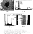
도 1a는 종래 기술의 섬유 브러시의 팁들을 나타낸 SEM 사진이다.
도 1b는, 도 1a 내의 지시된 박스 내에서 얻은, 섬유들의 팁들의 EDAX 분석으로, 섬유 팁들 위에, 은과 구리에 더하여, 금이 존재하는 것을 나타내고 있다.
도 1c는 도 1d에 도시된 섬유의 EDAX 분석으로, 섬유가 Ag/Cu 합금으로 만들어지는 것을 확증하고 있다.
도 1d는 재료 기준으로서의 Ag/Cu 섬유의 SEM 사진이다.
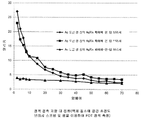
도 2는 은도금 회전자 링 위에 있는 두 개의 Ag/Cu FOT 브러시에 대한 그리고 금도금 회전자 링 위에 있는 Ag/Cu FOT 브러시에 대한 정적 접촉 저항 대 전류 그래프이다.
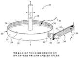
도 3은, 브러시와 링이 액체 질소의 풀(pool)에 잠겨 있는 상태에서의 FOT 정적 저항 측정을 위한 소진폭 회전자 진동 능력을 갖는 시험 장치를 개략적으로 도시한 등각투상도이다.
도 4a는 고 컴플라이언스 Au/Cu FOT 브러시의 팁들을 나타낸 SEM 사진이다.
도 4b는 도 4a에 지시된 박스 내에서 얻은 섬유들의 팁들의 EDAX 분석으로, 섬유 팁들 위에, 은과 구리에 더하여, 금이 존재하는 것을 나타내고 있다.
도 4c는 도 4d에 도시된 섬유의 EDAX 분석으로, 섬유가 Ag/Cu 합금으로 만들어지는 것을 확인해주고 있다.
도 4d는 재료 기준으로서의 Ag/Cu 섬유의 SEM 사진이다.
도 5는 드럼형 다채널 초전도 슬립-링을 개략적으로 도시한 등각투상도이다.
도 6은 액체 질소에 잠길 때 30rpm으로 회전하는 고 컴플라이언스 FOT 브러시에 의한 그리고 0 내지 180A의 전류에 대한 전압 강하 대 전류 및 접촉 저항 대 전류의 그래프이다.
도 7은 본 발명의 원리를 채택한 팬케익형 다채널 초전도 슬립-링을 개략적으로 도시한 평면도이다.
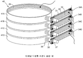
도 8은 캔틸레버 브러시-스프링 및 회전자의 내경부에 부착되는 초전도 리본을 구비하는 개선된 드럼형 슬립-링을 개략적으로 도시한 도면이다.
도 9는 FOT 브러시와 초전도 캔틸레버 스프링을 구비하는 개선된 디스크-전기자 호모폴라 모터/발전기를 개략적으로 도시한 도면이다.
도 10은 캔틸레버 브러시-스프링 및 투가 전류 용량을 위한 추가 FOT 브러시 조립체를 구비하는 개선된 초전도 드럼형 슬립-링을 개략적으로 도시한 도면이다.
도 11a는 니게이터 스프링 및 FOT 브러시 조립체를 구비하는 초전도 드럼형 슬립-링을 개략적으로 도시한 도면이다.
도 11b는 금속 브러시 홀더의 중앙에서 초전도 리본과 도통하는 도선 위의 초전도 리본을 상세하게 도시한 도면이다.
도 12a는 캔틸레버 스프링의 원측 단부에 설치되는 니게이터 스프링 및 FOT 브러시 조립체를 구비하는 개선된 초전도 드럼형 슬립-링을 개략적으로 도시한 도면이다.
도 12b는 금속 브러시 홀더의 중앙에서 초전도 리본과 연통하는 도선 위의 초전도 리본을 상세하게 도시한 도면이다.1A is a SEM photograph showing tips of a prior art fiber brush.
Fig. 1B shows that EDAX analysis of the tips of the fibers, obtained in the indicated box in Fig. 1a, has gold on top of the fibers, in addition to silver and copper.
Fig. 1c confirms that the EDAX analysis of the fibers shown in Fig. 1d shows that the fibers are made of an Ag / Cu alloy.
Figure 1D is a SEM image of Ag / Cu fibers as a material reference.
Figure 2 is a graph of static contact resistance versus current for two Ag / Cu FOT brushes on a silver plating rotor ring and for an Ag / Cu FOT brush on a gold plated rotor ring.
3 is an isometric view schematically showing a test apparatus having a small amplitude rotor oscillation capability for FOT static resistance measurement in a state where the brush and ring are immersed in a pool of liquid nitrogen.
4A is a SEM photograph showing tips of a high compliance Au / Cu FOT brush.
Fig. 4b shows EDAX analysis of the tips of the fibers obtained in the box indicated in Fig. 4a, with gold present on the fiber tips, in addition to silver and copper.
Figure 4c confirms that the fibers are made of Ag / Cu alloy by EDAX analysis of the fibers shown in Figure 4d.
4D is a SEM photograph of Ag / Cu fiber as a material reference.
5 is an isometric view schematically illustrating a drum-type multi-channel superconducting slip-ring.
Figure 6 is a graph of voltage drop versus current versus contact resistance versus current for a current of 0 to 180 A with a highly compliant FOT brush rotating at 30 rpm when submerged in liquid nitrogen.
7 is a plan view schematically illustrating a pancake type multi-channel superconducting slip-ring adopting the principle of the present invention.
8 is a schematic illustration of an improved drum type slip-ring having a cantilever brush-spring and a superconducting ribbon attached to the inner diameter portion of the rotor.
9 is a schematic view of an improved disk-armature homopolar motor / generator with a FOT brush and a superconducting cantilever spring.
10 is a schematic illustration of an improved superconducting drum type slip-ring having a cantilever brush-spring and an additional FOT brush assembly for transmission current capacity.
11A is a schematic view of a superconducting drum type slip-ring having a thiger spring and a FOT brush assembly.
FIG. 11B is a view showing in detail the superconducting ribbon on the conductor, which is conductive with the superconducting ribbon at the center of the metal brush holder. FIG.
12A is a schematic view of an improved superconducting drum type slip-ring having a nose spring and an FOT brush assembly installed at the one end of a cantilever spring.
12B is a view showing in detail the superconducting ribbon on the conductive line communicating with the superconducting ribbon at the center of the metal brush holder.
우선, 다수의 도면들을 일관하여 유사한 도면 번호가 동일한 구조 요소들, 부분들 또는 표면들을 지시하고자 하는 의도이며, 이는 이러한 요소들, 부분들 또는 표면들이 본 상세한 설명이 일체로 통합되어 있는 명세서 전체에 의해 추가적으로 기술되거나 설명될 수 있기 때문이라는 것을 명확하게 이해해야 한다. 달리 지시되지 않으면, 도면들은 명세서와 함께 파악되도록(즉, 크로스해칭(cross-hatching), 부품들의 배치 형태, 비율, 각도 등) 의도되고, 본 발명의 명세서 전체의 일부분으로 간주되어야 할 것이다. BRIEF DESCRIPTION OF THE DRAWINGS At the outset, it is intended that many of the drawings be referred to by way of identical structural elements, portions or surfaces, and that such elements, portions or surfaces are not necessarily drawn to scale throughout the specification, As will be apparent to those skilled in the art. Unless otherwise indicated, the drawings are intended to be taken in conjunction with the specification (i.e., cross-hatching, arrangement of parts, ratio, angle, etc.) and should be considered a part of the entire specification of the present invention.
먼저, 본 명세서에서 사용된 동일한 참조 번호들은 여러 도면들에 걸쳐 동일한 구조적 요소, 부분 또는 표면을 일관되게 지칭하도록 사용되었으며, 그러한 요소, 부분 또는 표면들은 하기 구체적 내용과 이를 통합된 일부분으로 하는 전체 명세서를 통해서도 추가로 더 묘사되고 설명되고 있음을 주지할 필요가 있다. 달리 명시하지 않는 한, 도면들은 명세서와 함께 파악할 수 있도록 했는데(예, 단면표시, 부품의 배열, 비율, 각도 등), 이 도면들은 본 발명의 전체 문서의 일부로서 고려되어야 한다. 후술하는 설명에서 사용되듯이, "수평", "수직", "좌", "우", "상향", "하향"과 같은 형용사들과 형용사형 파생어들(예, "수평적", "우향의", "상향의" 등)은 해당 도면이 독자를 마주하는 상태에서의 묘사되는 구조물의 방향을 지칭할 뿐이다. 마찬가지로, '안쪽'그리고 '바깥쪽'과 같은 용어는, 필요에 따라 연장축 또는 회전축에 대한 표면의 방향을 일반적으로 지칭한다.First, the same reference numerals used in the present specification are used to refer to the same structural element, part or surface throughout the various drawings, and such element, part or surface is to be understood to be embodied in the following detailed description and the accompanying claims, It should be noted that the above description is further described and explained through Unless otherwise specified, drawings are to be understood with reference to the specification (e.g., cross-sectional views, component arrangements, ratios, angles, etc.), which should be considered part of the overall document of the present invention. As used in the following description, the terms adjectives such as "horizontal", "vertical", "left", "right", "upward", "downward" and adjective derivatives (eg, "horizontal" Quot ;, "upward ", etc.) refer only to the direction of the structure depicted in the state in which the drawing faces the reader. Likewise, terms such as 'inside' and 'outside' generally refer to the orientation of the surface with respect to the extension axis or axis of rotation, as needed.
실험적인 초전도 슬립-링에서의 회전자 링으로부터 섬유 팁들로의 금의 이전(도 1a 내지 도 1d)The transfer of the gold from the rotor ring to the fiber tips in the experimental superconducting slip-ring (Figs. La-d)
이제 도면들, 특히 그 중에서도 도 1a 내지 도 1d를 참조하면, 이 네 개의 도면들은 도 1a에 도시된 종래 기술의 브러시 다발의 주사 전자 현미경("SEM":Scanning Electron Microscope)/에너지 분산형 X선 형광 분석기("EDAX":Energy Dispersive X-ray Spectrometer) 분석을 도시하고 있다.Referring now to the drawings, and more particularly to FIGS. 1A-1D, these four drawings illustrate the prior art brush bundle scanning electron microscope ("SEM") / energy dispersive X- And an Energy Dispersive X-ray Spectrometer ("EDAX ") analysis.
다발 내의 개별 섬유들은 은/구리("Ag/Cu") 합금으로 이루어져 있다. 섬유들은 고정자 위에 설치되어 있고, 액체 질소에 잠겨 있으며, 섬유들의 팁들이 회전자의 금으로 된 전기도금 층에 미끄럼 계합되도록 배치되어 있다. 도 1a는 다발 내의 섬유들의 원측 단부들의 SEM 사진이며, 다발들이 원형 FOT 배열 형태(즉, 최중앙 섬유들이 제거되지 않음)를 가지는 것으로 나타내고 있다. 도 1b는, 도 1a 내의 지시된 박스 내에서 얻은, 섬유 팁들의 EDAX 분석이다. 도 1b는 섬유 팁들 위에, 은과 구리에 더하여, 금이 존재하는 것을 나타내고 있다.Individual fibers in the bundle consist of a silver / copper ("Ag / Cu") alloy. The fibers are mounted on the stator, immersed in liquid nitrogen, and arranged so that the tips of the fibers slide in engagement with the gold plated electroplating layer of the rotor. Figure 1a is a SEM photograph of the distal ends of the fibers in the bundle, showing that the bundles have a circular FOT arrangement (i.e., the center fibers are not removed). 1B is an EDAX analysis of the fiber tips obtained in the indicated box in FIG. 1A. 1B shows that gold is present on the fiber tips in addition to silver and copper.
금의 유일한 공급원이 회전자 위의 금으로 된 전기도금 층이기 때문에, 도 1b는, 전기도금된 회전자 링으로부터 나온 금이 회전자 링으로부터 실험적인 초전도 슬립-링 내의 다발 내의 섬유들의 팁들로 이전된 것을 나타내고 있다.Since the only source of gold is the gold electroplated layer on the rotor, Figure 1b shows that gold from the electroplated rotor ring migrates from the rotor ring to the tips of the fibers in the bundle in the experimental superconducting slip- .
도 1c는 재료 기준으로서의 Ag/Cu 섬유의 중간부를 EDAX 분석한 것이다. 도 1d는 도 1D에 도시된 섬유의 중간부의 SEM 사진이다. 은/구리 섬유들의 팁들 위에 금이 존재하는 것(도 1a 내지 도 1d)은 금이 회전자 링으로부터 섬유들의 팁들로 이전된 것을 확증하는 것이다.Figure 1C is an EDAX analysis of the middle portion of Ag / Cu fibers as a material reference. FIG. 1D is a SEM photograph of the middle portion of the fiber shown in FIG. 1D. The presence of gold on the tips of silver / copper fibers (Figs. La-d) confirms the transfer of the gold from the rotor ring to the tips of the fibers.
전기 접촉 저항 대 전류(도 2)Electrical contact resistance vs. current (Figure 2)
도 2는 도 1a 내지 도 1d에 부분적으로 도시된 고정자 설치형 초전도 브러시-스프링 및 회전자 링의 액체 질소의 풀(pool)(미도시)에 잠긴 때의 정적 FOT 접촉 저항(세로축) 대 전류(가로축) 그래프이다. Figure 2 shows the static FOT contact resistance (vertical axis) versus current (horizontal axis) as it is submerged in a pool of liquid nitrogen (not shown) of the stator-mounted superconducting brush-spring and rotor ring, ) Graph.
접촉 저항은 밀리옴으로 표시되고, 전류는 암페어로 표시된다. 정사각형 데이터 점들 그리고 다이아몬드형 데이터 점들을 연결하는 두 개의 곡선은 은도금 회전자 링 위에 놓이는 Ag/Cu FOT 브러시에 대해 얻어진 값들을 나타낸다. 삼각형 데이터 점들을 연결하는 곡선은 금도금 회전자 링 위에 놓이는 Ag/Cu FOT 브러시 링에 대해 얻어진 값들을 나타낸다.The contact resistance is expressed in milli-ohms and the current in amps. The square data points and the two curves connecting the diamond-shaped data points represent the values obtained for the Ag / Cu FOT brushes placed on the silver plating rotor ring. The curves connecting the triangle data points represent the values obtained for the Ag / Cu FOT brush ring placed on the gold plated rotor ring.
이 곡선들은, 은도금 링들 위에 놓인 Ag/Cu FOT 브러시들의 접촉 저항이 전류가 0에서 30암페어로 증가함에 따라 가파르게 감소되고 나서 30 내지 70암페어 사이에서는 수평을 유지(즉, 덜 가파르게 떨어짐)하는 것을 나타내고 있다. 한편, 금도금 회전자 링 위에 놓인 Ag/Cu FOT 브러시의 접촉 저항은 0 내지 70 암페어의 전체 전류 범위에서 실질적으로 일정하다. 이는 금 링 위에서 미끄러지는 금 팁을 구비한 Ag/Cu 섬유들의 불활성을 확증한다. These curves show that the contact resistance of the Ag / Cu FOT brushes placed on silver-plated rings decreases steeply as the current increases from zero to 30 amperes and then remains horizontal (i.e., falls less steeply) between 30 and 70 amperes have. On the other hand, the contact resistance of an Ag / Cu FOT brush placed on a gold plated rotor ring is substantially constant over the entire current range of 0 to 70 amperes. This confirms the inertness of the Ag / Cu fibers with the gold tip slipping on the gold ring.
드럼형 단채널 시험 장치(도 3)A drum type short channel test apparatus (FIG. 3)
도 3은 브러시와 링이 액체 질소의 풀(미도시)에 잠겨 있는 상태에서의 도 2에 도시된 정전 FOT 접촉 저항 측정을 위한 시험 장치를 개략적으로 도시한 도면이다. 이 장치는 소진폭 진동을 겪지만 회전하지는 않도록 설계된 단채널 드럼형 슬립-링이다.Fig. 3 is a view schematically showing a test apparatus for measuring the electrostatic FOT contact resistance shown in Fig. 2 in a state in which the brush and ring are immersed in a pool of liquid nitrogen (not shown). The device is a short-channel drum-type slip-ring that is designed not to rotate but undergo minor vibration.
대체로 20으로 지시되는 이 장치는, 중앙 수직 원통 샤프트(23)의 축선(y-y)을 중심으로, 아치형 선(22) 위의 양방향 화살표로 지시된 바와 같이, 양쪽 각도 방향으로 소진폭으로 진동하도록 배치된, 위를 바라보는 컵 형상의 회전자(21)를 구비한다. 회전자는 그 내경부(26)에 부착되고 도선(30)을 구비하는 초전도 리본(29)을 구비하는 것으로 도시되어 있다. 회전자는 샤프트에 연결되는 환형 수평 베이스(24)를 구비한다. 링(25)은 샤프트(23)의 축선 둘레에 생성되고 내부 및 외부를 각각 바라보는 원통형 표면들(26, 28)을 구비한다.This device, generally indicated at 20, is arranged to oscillate at a minor width in both angular directions, as indicated by the double arrows on the
고정자 설치형 전류-운반 브러시-스프링(31)이 하나의 초전도 리본(32)을 구비하고, 이에 따라 형성되는 조립체는 대체로 34로 지시된다. 도전체(31)는 직사각형 횡단면을 갖는 수평으로 가늘고 긴 막대형 부재인 것으로 도시되어 있다. 초전도 리본(32)은 또한 직사각형 횡단면을 갖는 수평으로 가늘고 긴 막대형 부재인 것으로 도시되어 있다. 리본(32)은 솔더링 등에 의해 도전체(31)의 마주보는 면에 적절하게 고정될 수 있다. 리본-도전체 서브 조립체(34)의 근측 주변 단부(proximal marginal end portion)들이 고정자(미도시)에 설치된다. 리본(32)은 도선(38)에 의해 접속된다. 적당한 전압원(±ΔV)이 도선들(30, 38) 사이에 배치되어 전류가 전압원으로부터 슬립-링을 통해 다시 전압원으로 흐르게 만든다. The stator-mounted current-carrying brush-
섬유 브러시 조립체(35)가 리본-도전체 조립체(34)의 원측 주변 단부에 설치된다. 브러시 조립체는 브러시 튜브(37) 내에 설치되는 다수의 금속 섬유(36)를 포함하는 섬유 브러시(36)를 포함한다. A
장치(20) 전체가 적당한 액체 질소와 같은 적당한 극저온 액체의 풀(미도시)에 잠긴다. 리본(32)이 실온에서 약간의 전기 저항을 가지는 반면, (액체 질소에 잠길 때와 같이) 전이 온도 미만으로 냉각될 때, 리본은 실질적으로 영인 전기 저항을 갖는다. 전류가 최소 전기 저항 경로를 통해 리본-도전체 서브조립체(34)를 따라 고정자로부터 브러시 조립체(35)로 운반되기 때문에, 잠긴 리본-도전체 조립체(34)는 실질적으로 영인 전기 저항으로 초전도 리본(32)을 따라 고정자와 브러시 조립체 사이에서 고전류를 운반할 수 있다. 회전자의 반경 방향 두께를 통과한 후에, 이렇게 전달되는 전류는 회전자 링의 내부 위에 있는 초저도 리본(29)에 의해 운반될 수 있고, 전압원으로 복귀될 수 있다.The
고 컴플라이언스의 개선된 FOT 브러시들을 이용한 초전도 슬립-링에서의 회전자 링으로부터 섬유 팁들로의 금의 이전(도 4a 내지 도 4d)The transfer of gold from the rotor ring to the fiber tips in the superconducting slip-ring using improved FOT brushes of high compliance (Figs. 4A-D)
도 4a 내지 도 4d는 고 컴플라이언스 브러시 다발을 이용한 초전도 슬립-링(즉, 최중앙 섬유들이 제거됨)의 SEM/EDAX 분석을 도시한다.Figures 4A-4D illustrate SEM / EDAX analysis of a superconducting slip-ring using high compliance brush bundles (i.e., removal of the center fibers).
도 1a에 도시된 종래 기술의 브러시 다발과 같이, 도 4a에 도시된 고 컴플라이언스 브러시 다발 내의 개별 섬유들도 또한 은/구리 합금으로 형성된다. 브러시 다발은 고정자 위에 설치되었고, 액체 질소에 잠겼고, 그리고 섬유들의 팁들이 회전자의 금으로 된 도금 층에 미끄럼 계합되도록 배치되었다. 도 4a는 다발 내의 섬유들의 원측 단부들의 SEM 사진이며, 다발이 개선된 고 컴플라이언스 FOT 배열 형태(즉, 최중앙 섬유들이 제거됨)를 가지는 것으로 나타내고 있다. 도 4b는, 도 4a 내의 지시된 박스 내에서 얻은, 섬유 팁들의 EDAX 분석이다. 도 4b는 섬유 팁들 위에, 은과 구리에 더하여, 금이 존재하는 것을 나타내고 있다. 이는 전기도금된 회전자 링으로부터 나온 금이 회전자 링(즉, 금의 유일한 공급원)으로부터 다발 내의 은/구리 섬유들의 팁들로 이전된 것을 확증한다.Like the prior art brush bundle shown in FIG. 1A, individual fibers in the high compliance brush bundle shown in FIG. 4A are also formed of a silver / copper alloy. The brush bundle was placed on the stator, immersed in liquid nitrogen, and the tips of the fibers were placed in sliding engagement with the gold plated layer of the rotor. FIG. 4A is a SEM image of the distal ends of the fibers in the bundle, indicating that the bundle has an improved high compliance FOT alignment configuration (i.e., the center fibers removed). Figure 4b is an EDAX analysis of the fiber tips obtained in the indicated box in Figure 4a. FIG. 4B shows that gold is present on the fiber tips in addition to silver and copper. This confirms that the gold from the electroplated rotor ring was transferred from the rotor ring (i.e., the only source of gold) to the tips of the silver / copper fibers in the bundle.
도 4c는 재료 기준으로서의 Ag/Cu 섬유의 중간부를 EDAX 분석한 것이다. 도 4d는 섬유의 중간부의 SEM 사진이다. 은/구리 섬유들의 팁들 위에 금이 존재하는 것은 금이 회전자 링으로부터 섬유들의 팁들로 이전되었음을 확증한다.Figure 4c is an EDAX analysis of the middle portion of Ag / Cu fibers as a material reference. 4D is a SEM photograph of the middle portion of the fiber. The presence of gold on the tips of the silver / copper fibers confirms that the gold has been transferred from the rotor ring to the tips of the fibers.
드럼형 다채널 초전도 슬립-링(도 5)Drum-type multi-channel superconducting slip-ring (Figure 5)
도 5에는, 대체로 40으로 지시되는 드럼형 다채널 초전도 슬립-링이 중간 절연 장벽들에 의해 분리되는 다수의 수직-스택(vertically-stacked) 링(41)을 구비하는 것으로 도시되어 있는데, 중간 절연 장벽들은 그 각각의 측면에 링을 지지하는 어깨부들을 구비한다. 여러 링들은 41로 각각 지시되고, 개별적으로는 각각 문자 "A", "B", "C", "D"에 의해 구별된다. 따라서 최상측 링은 41A로 지시되고, 다음 하측 링은 41B로 지시되고, 세 번째 하측 장치는 41C로 지시되고, 최하측 링은 41D로 지시된다.5 shows a drum-type multi-channel superconducting slip-ring, indicated generally at 40, having a plurality of vertically-stacked rings 41 separated by intermediate insulating barriers, The barriers have shoulders that support the ring on each side thereof. The various rings are designated 41 respectively and are individually distinguished by the letters "A "," B ", "C ", and" D ", respectively. Thus, the top ring is designated 41A, the next lower ring is designated 41B, the third bottom device is designated 41C, and the bottom ring is designated 41D.
다수의 수직으로 이격된 고정자 설치형 적층식(laminated) 리본-도전체-리본 서브조립체가 장치당 하나씩 있다. 개별 서브조립체(34)는 개별적으로는 각각 문자 "A", "B", "C", "D"에 의해 구별된다. 서브조립체(34A)는 최상측 링(41A)과 연관되고, 다음 하측 서브조립체 (34B)는 링(41B)과 연관되고, 다음 조립체(34C)는 링(41C)과 연관되고, 최하측 서브조립체(34D)는 링(41D)과 연관된다. 이 서브조립체들은 앞에서 설명한 바와 같고, 그것들로부터 나오는 도선들이 교호하여 DC 전압원들에 접속된다. 따라서 최상측 도선은 양극 전압원에 접속되고, 두 번째 하측 도선은 음극 전압원에 접속되고, 세 번째 하측 도선은 양극 전압원에 접속되고, 네 번째 하측 도선은 음극 전압원에 접속된다. 인접한 리본-도전체-리본 서브조립체(34)들 간의 수직 간격은 서브조립체들 각각이 바로 이웃한 서브조립체와 전기적으로 절연되는 것을 보장한다.There are a number of vertically spaced stator-mounted laminated ribbon-conductor-ribbon subassemblies per device. The individual subassemblies 34 are distinguished individually by the letters "A "," B ", "C ", and" D ", respectively. The
따라서 도 5의 드럼형 다채널 슬립-링(40)은 네 개의 링들(41A, 41B, 41C, 41D)을 구비하는 것으로 도시되어 있다. 절연 장벽들은 링들 사이의 공간들 내에 배치되어 네 개의 링들 각각을 인접한 이웃 링들로부터 전기적으로 절연시킨다. 유사하게, 여러 리본-도전체-리본 조립체(34)들이 서로 수직으로 이격되어 있고, 이들은 교호하여 DC 전압원들에 접속된다.Thus, the drum-type multichannel slip-
전체 장치(40)가 액체 질소와 같은 적당한 극저온 유체에 잠겨서 초전도 재료(들)의 온도를 재료 각각의 전이 온도(들) 미만으로 낮춘다. 따라서 이 장치는, 다른 채널들과 절연되는 별도의 채널을 제공하는, 각각의 회전자(41A, 41B, 41C, 41D)와 이들과 각각 연관된 리본-도전체-리본 브러시-스프링 조립체(34A, 34B, 34C, 34D) 간의 전기 접속을 갖는 드럼형 다채널 슬립-링을 제공한다.The
초전도 리본들(32, 33)은 직사각형 단면을 갖는 수평으로 가늘고 긴 막대형 부재들인 것으로 도시되어 있다. 리본들은 바람직하게는 동일한 초전도 재료로 형성되고 치수가 동일하여, 장치가 극저온 유체에 잠길 때, 회전자 위의 리본-도전체 스프링 조립체에 의해 가해지는 힘이 초전도 리본들의 존재에 의해 영향을 받지 않을 것이다.The
전압 강하와 접촉 저항 대 전류(도 6)Voltage drop and contact resistance vs. current (Figure 6)
도 6은, 고 컴플라이언스 FOT 브러시들을 구비한, 도 5에 도시된 것과 같은, 장치의 전압 강하(왼쪽 세로축)와 접촉 저항(오른쪽 세로축) 대 전류(가로축)의 그래프이다. 전압 강하는 전압으로 표현되고, 접촉 저항은 밀리옴으로 표현되고, 전류는 암페어로 표현된다. 섬유들의 팁들은 150g의 힘으로 회전자 링의 외부 표면 위에서 링에 계합되도록 압박된다. Figure 6 is a graph of the voltage drop (left ordinate) and contact resistance (right ordinate) vs. current (abscissa) of the device, as shown in Figure 5, with high compliance FOT brushes. The voltage drop is expressed as voltage, the contact resistance is expressed in milli-ohms, and the current is expressed in amperes. The tips of the fibers are pressed against the ring on the outer surface of the rotor ring with a force of 150 g.
전압 강하 대 전류는 정사각형 데이터 점들을 통해 그려지는 직선인 것으로 도시되어 있다. 이 선은 0.22볼트 및 20암페어에 있는 하나의 극점과 0.50볼트와 180암페어에 있는 다른 극점 사이에서 연장하는 것으로 도시되어 있다. 따라서 전압 강하는 전류가 증가함에 따라 실질적으로 선형으로 상승한다.The voltage drop versus current is shown as being a straight line drawn through the square data points. This line is shown to extend between one pole at 0.22 volts and 20 amps and another pole at 0.50 volts and 180 amps. Therefore, the voltage drop rises substantially linearly as the current increases.
접촉 저항 대 전류는 삼각형 데이터 점들을 연결하는 곡선에 의해 도시되어 있다. 곡선은 20암페어에서의 5.6밀리옴으로부터 약 70암페어에서의 약 2밀리옴까지 가파르게 떨어지고 나서 70 내지 180암페어의 범위에서는 180암페어에서의 약 1.4밀리옴의 최종값에 도달할 때까지 수평을 유지(즉, 덜 가파르게 떨어짐)하는 것으로 보인다. 따라서 전류가 20암페어로부터 180암페어까지 증가함에 따라 전압 강하가 실질적으로 선형으로 증가하는 반면, 동일하게 증가하는 전류 범위에서 접촉 저항은 (처음에는 가파르게 그리고 나서는 덜 가파르게) 감소한다.The contact resistance versus current is shown by the curve connecting triangle data points. The curve steeply falls from 5.6 milliohms at 20 amps to about 2 milliohms at about 70 amps and then remains horizontal until reaching a final value of about 1.4 milliohms at 180 amps in the range of 70 to 180 amps That is, less steeply falling). Thus, as the current increases from 20 amps to 180 amps, the voltage drop increases substantially linearly, while at the same increasing current range the contact resistance decreases (initially steeply and then less steeply).
도 6(30rpm에서 측정)은 FOT 브러시 접촉 저항이 밀리옴 범위에 있고, 전류가 증가됨에 따라 감소하는 것을 나타내고 있다. 따라서 총 소유 비용이 보다 적은 접촉점들을 가지며 이에 따라 보다 높은 접촉 저항을 갖는 브러시보다 작다. 이러한 측정을 하기 위한 장치는 도 5에 도시되어 있다.Figure 6 (measured at 30 rpm) shows that the FOT brush contact resistance is in the milliohm range and decreases with increasing current. Thus, the total cost of ownership is less than brushes with less contact points and thus higher contact resistance. An apparatus for making such a measurement is shown in Fig.
팬케익형 다채널 초전도 슬립-링(도 7)The pancake-type multi-channel superconducting slip-ring (Figure 7)
도 7은 본 발명의 원리가 팬케익형 다채널 슬립-링에서 실시되는 법을 나타낸다.Figure 7 illustrates how the principles of the present invention are implemented in a pancake type multi-channel slip-ring.
도 7에서, 대체로 50으로 지시되는 개선된 장치가 수직축선(52)을 중심으로 회전되도록 구성된 회전자(51)를 포함하는 것으로 도시되어 있다. 도 7이 슬립-링의 평면도이기 때문에, 축선(52)은 지면에 대해 수직이고, 점 표식으로 표현되어 있다. 회전자는 평면에서 볼 때 원형 또는 환형 부재이고, 다수의 동심 링들을 구비한다. 이 링들은 각각 53으로 지시되고, 개별적으로는 축선(52)으로부터 반경 방향 외측으로 가면서 각각 문자 "A", "B", "C", "D"에 의해 구별된다. 앞에서 언급한 바와 같이, 각각의 링은 회전축선(52)을 중심으로 생성된다.In Fig. 7, an improved device, indicated generally at 50, is shown to include a
각각 58로 지시되는 환형 절연 장벽들이 인접한 링들 사이의 회전자의 벽 내에 위치되어 각각의 링을 인접한 이웃 링(들)로부터 전기적으로 절연시키고 이들 간의 교차 결합을 방지한다. 구체적으로, 제1 절연 장벽이 링들(53A, 53B) 사이의 벽에 있고, 제2 절연 장벽은 링들(53B, 53C) 사이의 벽에 있고, 제3 절연 장벽은 링들(53C, 53D) 사이의 벽에 있다. Annular insulation barriers, designated 58 respectively, are located in the walls of the rotor between adjacent rings to electrically isolate each ring from adjacent neighboring ring (s) and prevent cross-coupling therebetween. Specifically, the first insulating barrier is on the wall between the rings 53A and 53B, the second insulating barrier is on the wall between the rings 53B and 53C, and the third insulating barrier is between the rings 53C and 53D. It is on the wall.
각각 59로 지시되고 실질적으로 위에서 설명한 바와 같은 다수의 캔틸레버 설치형 스프링 조립체가 여러 링들 위에 놓이도록 배치된다. 이 스프링들 각각은 근측 주변 단부들이 고정자 위에 설치되는, 위에서 설명한 바와 같은, 리본-도전체-리본 적층체이다.A plurality of cantilevered spring assemblies, designated 59 and substantially as described above, are disposed on the various rings. Each of these springs is a ribbon-conductor-ribbon laminate, as described above, with proximal peripheral ends mounted on the stator.
또한 각각 35로 지시되는 브러시 조립체들이 스프링(59)들의 원측 주변 단부들 위에 설치된다. 각각의 브러시 조립체는 관련되는 링의 표면에 계합되도록 배치되는 다수의 FOT 설치형 브러시 섬유들을 구비한다. 링 마다 두 개의 캔틸레버 설치형 스프링들이 있고, 이 스프링들은 회전자 위에서 12시 방향 위치 및 6시 방향 위치 가까이에 배치된다. 링(53A)과 연관된 스프링들은 59A, 59A로 지시되고, 링(53B)과 연관된 스프링들은 59B, 59B로 지시되고, 링(53C)과 연관된 스프링들은 59C, 59C로 지시되고, 그리고 링(53D)과 연관된 스프링들은 59D, 59D로 지시된다. Also, brush assemblies, each designated 35, are mounted on the distal peripheral edges of the springs 59. Each brush assembly has a plurality of FOT-installed brush fibers arranged to engage a surface of an associated ring. There are two cantilevered springs per ring, which are arranged on the rotor near the 12 o'clock position and the 6 o'clock position. The springs associated with ring 53A are designated 59A and 59A and the springs associated with ring 53B are designated 59B and 59B and the springs associated with ring 53C are designated 59C and 59C, Are indicated by 59D, 59D.
각각의 스프링 위에 설치되는 다수의 브러시 조립체를 구비할 수 있는 드럼형 실시예(예컨대 도 10 참조)와 마찬가지로, 팬케익형 실시예는 스프링들의 원측 주변 단부들 위에 다수의 브러시 조립체를 구비할 수 있어, 섬유 팁들과 여러 링들의 바닥 표면들 간의 적절하고 연속적인 전기 접촉을 보장할 수 있다. 또한, 환형 초전도 리본들이 각 링의 외경부 및 내경부 위에 각각 위치되는 것에 유의하자.Like the drum-shaped embodiment (see, e.g., FIG. 10), which may have multiple brush assemblies mounted on each spring, the pancake-like embodiment may have multiple brush assemblies on the distal- It is possible to ensure proper and continuous electrical contact between the fiber tips and the bottom surfaces of the various rings. Also note that annular superconducting ribbons are located on the outer diameter portion and the inner diameter portion of each ring, respectively.
캔틸레버 설치형 브러시-스프링의 양측 및 회전자의 내경부에 부착되는 초전도 리본들을 구비하는 드럼형 슬립-링(도 8)(Figure 8) with superconducting ribbons attached to both sides of the cantilevered brush-spring and the inner diameter portion of the rotor,
도 8은 대체로 60으로 지시되는 개선된 드럼형 슬립-링을 개략적으로 도시하는 도면이며, 도시된 슬립-링은 고정자(61)와 회전자(62) 사이에서 전력 및/또는 신호를 전송하도록 작동하게 배치되어 있다.8 schematically illustrates an improved drum-type slip-ring generally designated 60, and the illustrated slip-ring is operable to transmit power and / or signals between the
대체로 63으로 지시되는 캔틸레버-설치형 스프링 조립체는 그 왼쪽 단부 또는 근측 단부가 고정자(61) 위에 설치되고, 오른쪽 단부 또는 원측 단부가 회전자 가까이에 배치된다. 이 스프링 조립체는 중앙의 수평으로 가늘고 긴 전류-운반 브러시-스프링(64)을 구비하고, 이 중앙 도전체의 상부 표면 및 하부 표면 위에 설치되고 초전도 재료로 이루어진 리본들(65, 65)을 구비한다. 중앙 도전체는 베릴륨구리(BeCu)와 같은 적당한 재료로 형성될 수 있고, 횡단면이 대체로 직사각형이다. 따라서 중앙 도전체는 각각 수평으로 가늘고 긴 평평한 직사각형의 상부 표면(66) 및 하부 표면(68)을 구비한다. 중앙 도전체의 주된 기능 두 가지는 (1) 근측 단부와 원측 단부 사이에서 전류를 운반하는 초전도 리본들을 지지하는 것과, (2) 근측 단부와 원측 단부 사이에서 판스프링(flexure spring)으로 작용하여 섬유 브러시 조립체(69)의 팁들을 회전자의 외부 표면 위에 도금된 금 링(70)에 압박하는 것이다. 초전도 리본들(65, 65)은 중앙 도전체의 상부 표면과 하부 표면에 설치된다. 이 두 개의 리본은 수평으로 가늘고 길며, 바람직하게는 동일한 초전도 재료로 형성된다. 리본들은 적당하게는 중앙 도전체의 상부 표면과 하부 표면에 솔더링 또는 이와 유사한 방법으로 고정된다. 초전도 리본들(65, 65)의 주된 기능은 (1) 전체 장치가 극저온 유체에 잠겨서 리본들(65, 65)이 형성되는 재료의 온도를 그 전이 온도 미만으로 낮출 때, 고정자로부터 브러시 조립체까지의 전류 흐름에 대해 저항이 실질적으로 영인 경로를 제공하는 것과, (2) 장치가 극저온 유체에 잠길 때 스프링 조립체가 (바이메탈 스트립처럼) 상방으로 또는 하방으로 만곡되는 경향을 없애는 것의 두 가지이다.A cantilever-mounted spring assembly, generally indicated at 63, has its left end or proximal end mounted on the
브러시 조립체(69)는 스프링 조립체의 원측 주변 단부 위에 설치된다. 이 브러시 조립체는 금속 섬유 브러시들의 다발(71)을 그 안에 포함한다. 이 다발 내의 개별 섬유들은 은/구리 합금으로 형성될 수 있다. 브러시 다발의 상측 주변 단부는 브러시 튜브(72) 내에 수용되어 유지된다. 이 브러시 다발 내의 개별 섬유들의 하측 단부들은 회전자의 외부 표면 위의 링(70)에 계합되는 팁들에서 종료된다. The
회전자(62)는 축선(74)을 중심으로 회전하기 위해 설치되는 환형 부재인 것으로 도시된다. 축선이 도 8내에서 지면으로부터 나오기 때문에 축선은 점 표식으로 표현된다. 회전자는 금 전착된 얇은 환형 링(70)을 그 원통형 외부 표면 위에 구비하고, 원통형 내부 표면을 구비한다. 환형 초전도 리본(77)이 회전자 내부 표면(76) 위에 설치된다. 구체적으로, 리본(77)은 회전자 내부 표면(76)에 솔더링에 의해 적당하게 고정되는 원통형 외부 표면(78)과 원통형 내부 표면(79)을 구비한다. The
전압은 스프링 조립체의 근측 단부와 회전자 사이에서 선택적으로 인가될 수 있고, 이에 따라 전류가 고정자로부터 회전자로 흐르게 될 수 있다.The voltage can be selectively applied between the proximal end of the spring assembly and the rotor, so that current can flow from the stator to the rotor.
전체 장치가 액체 질소와 같은 적당한 극저온 유체에 잠겨서 초전도 리본(65, 65, 77)의 온도를 리본들 각각의 전이 온도 미만으로 낮추고, 이에 따라 리본들은 리본들을 통과하는 전류에 대한 저항이 실질적으로 영이 될 것이다.The entire device is submerged in a suitable cryogenic fluid such as liquid nitrogen to lower the temperature of the
따라서, 장치가 극저온 유체에 잠길 때, 전류가 고정자로부터 스프링 조립체(63)의 길이를 따라 브러시 조립체(69)로 흐를 것이다. 리본들(65, 65)의 온도가 전이 온도 미만일 것이고 저항이 실질적으로 영일 것이기 때문에, 리본들은 고정자와 브러시 조립체 사이에서의 전류 통과에 대한 최소 저항 경로일 것이다. 브러시 튜브를 통과한 후에, 전류는 브러시 다발의 길이를 따라 하방으로 지나가서 섬유들의 팁들로부터 회전자 링(70)으로 전달될 것이다. 회전자를 통과한 후에, 전류는 역시 저항이 실질적으로 영인 리본(77)에 의해 회전자의 다른 부품들(미도시)로 운반될 것이다.Thus, when the device is immersed in the cryogenic fluid, an electric current will flow from the stator to the
따라서, 이 실시예에서, 초전도 재료(들)의 전이 온도 미만인 극저온 유체에 슬립-링이 잠길 때, 초전도 리본들(65, 65, 77)은 고정자로부터 회전자까지의 전류 통과에 대한 최소 전기 저항 경로를 제공한다.Thus, in this embodiment, when the slip-ring is submerged in a cryogenic fluid that is below the transition temperature of the superconducting material (s), the
FOT 브러시들 및 캔틸레버형 초전도 스프링들을 구비하는 디스크 전기자 호모폴라 모터(도 9)A disk armature homopolar motor (Fig. 9) with FOT brushes and cantilever type superconducting springs
도 9는 개선된 디스크 전기자형의 호모폴라 모터 또는 발전기를 도시한 등각투상도이다.9 is an isometric view of a homo-polar motor or generator of an improved disk-arm type.
대체로 80으로 지시되는 개선된 모터는 고정자(미도시) 위에 설치되는 제1 캔틸레버 설치형 스프링 조립체(81)와 제2 캔틸레버 설치형 스프링 조립체(82)를 구비한다. 각각의 스프링 조립체는 고정자 위에 설치되는 근측 단부를 구비하고, 또한 대체로 83으로 지시되고 회전자 가까이에 배치되는 원측 단부를 구비한다. 각각의 스프링 조립체는 평평한 상부 수평 표면과 평평한 하부 수평 표면을 구비하는 중앙의 전류-운반 브러시-스프링(84)과 함께 솔더링 또는 이와 유사한 방법으로 스프링의 표면들에 고정되는 초전도 재료로 된 리본(85)을 구비하는 수평으로 가늘고 긴 샌드위치 구조인 것으로 도시되어 있다. 따라서 하나의 리본(85)은 중앙 도전체의 상부 표면에 고정되고, 다른 리본(85)은 그 하부 표면에 고정된다. 중앙 도전체는 베릴륨구리 또는 이와 유사한 것으로 형성되고, 횡단면이 직사각형인 것으로 도시되어 있다. 리본들(85, 85) 또한 횡단면이 직사각형인 것으로 도시되어 있다. 스프링의 양측면 위에 있는 리본의 목적은 전류 용량을 배가시키는 것이다. 이 리본들의 치수는 바람직하게는 동일한데, 이는 리본이 만들어지는 초전도 재료의 전이 온도(들) 미만인 극저온 유체에 잠길 때 스프링 조립체가 바이메탈 스트립처럼 만곡되는 경향을 없애기 위함이다. 도 9에서, 두 개의 스프링 조립체(81, 82)가 실질적으로 동일한 것으로 도시되어 있다. 그렇지만 반드시 그러해야할 필요는 없다. The improved motor, generally designated 80, includes a first cantilevered spring assembly 81 and a second cantilevered spring assembly 82 mounted on a stator (not shown). Each spring assembly has a proximal end that is mounted on the stator and also has a distal end generally designated 83 and disposed proximate the rotor. Each spring assembly includes a
도 9의 스프링 조립체들(81, 82)은 각각의 스프링 조립체의 원측 주변 단부들 위에 설치되는 두 개의 브러시 조립체(69)가 있다는 점에서 도 8의 스프링 조립체와 다르다. 앞에서 설명한 바와 같이, 각각의 브러시 조립체는 브러시 튜브(72)와 섬유 다발(71)을 포함한다. 섬유 다발은 적당한 은/구리 합금으로 만들어진 다수의 개별 섬유들을 포함하고 있다. 각각의 섬유 다발의 상측 주변 단부는, US 7,105,983 B2에 설명된 바와 같이, 연관된 브러시 튜브 내에 수용되어 유지된다. 각각의 다발 내의 섬유들은 아래에서 설명하는 바와 같이 회전자의 부분들에 미끄럼 계합되는 최하측 팁들에서 종료된다. 각각의 스프링 조립체 위에 두 개의 브러시 조립체가 있는 주된 이유는 전류 용량을 배가하기 위함이다.The spring assemblies 81, 82 of FIG. 9 differ from the spring assemblies of FIG. 8 in that there are two
회전자(83)는, 수평 축선(x-x)을 중심으로 회전하도록 축지지되는, 수평으로 가늘고 긴 특별하게 구성된 부재인 것으로 도시되어 있다. 축선(x-x)은 스프링 조립체들(81, 82)이 연장하는 축선들과 직교하게 배치된다. 회전자는 솔더링 또는 풀림 방지 기구(thread lock)를 갖는 나사와 같은 다른 적절한 방법에 의해 디스크에 연결되는 샤프트를 갖는 대경 디스크을 구비한다. 원주 방향으로 이격되고 반경 방향으로 연장하는 다수의 초전도 리본이 디스크의 양측면 위에 위치된다. 이 리본들은 디스크에 구비되고 반경 방향으로 연장하는 슬롯들 내에 수용된다. 디스크의 두께는 리본의 폭에 따라 정해질 것인데, 예를 들어 리본의 폭이 1/4"라면, 리본이 디스크의 양측면에 있는 슬롯들 내에 삽입될 수 있도록 디스크의 두께는 1/2"보다 두꺼울 것이다. 금으로 된 얇은 환형 또는 원통형 링(88)이 디스크(88)의 외부 표면 위에 전기도금되고, 여기에 제2 스프링 조립체(82)의 브러시들이 미끄럼 계합된다.The
회전자는 대경부 디스크에 결합되고 대경부 디스크로부터 축선 방향 왼쪽으로 연장하는 소경 샤프트(89)를 또한 구비한다. 금으로 된 얇은 벽을 갖는 환형 링(90)이 소경 샤프트(89)의 좌측 주변 단부 위에 전기도금되고, 여기에 제1 스프링 조립체(81) 내의 브러시들의 팁들이 미끄럼 계합된다. 각각 91로 지시되고 초전도 재료로 만들어지며 원주 방향으로 이격되고 종방향으로 연장하는 다수의 리본들이 각각의 스포크의 내측 단부들을 링(90)과 연결한다. The rotor also has a
사용 시에, 스프링 조립체들(81, 82)의 근측 단부들 사이에 전압(±ΔV)이 인가되고, 화살표들(84, 84)로 표현되는 자기장이 회전자를 종방향으로 통과한다. 회전자는 캔틸레버 설치식 스프링 조립체들(81, 82)에 대해 축선(x-x)을 중심으로 회전하고, 각각의 브러시 조립체들 내의 섬유들의 팁들은 각각 회전자 링들(90, 80)에 미끄럼 계합된다.In use, a voltage ([Delta] [Delta] V) is applied between the proximal ends of the spring assemblies 81, 82 and a magnetic field represented by
전류는 스프링 조립체(81)를 따라 외측으로, 그 원측 단부들에 브러시 조립체들을 통해 아래로, 회전자까지 흘러, 리본들(91)에 의해 회전자의 소경 샤프트(89)를 따라 허브 스포크들까지 운반되고, 스포크들을 따라 외측으로 대경 회전자부의 초전도 리본(86)까지 운반되고, 그리고 스프링 조립체(82)를 통해 다시 고정자까지 운반된다.The current flows outwardly along the spring assembly 81, down to the rotor through its brush assemblies at its distal ends, and reaches the hub spokes along the
전체 장치가 액체 질소와 같은 적당한 극저온 유체에 잠겨, 장치 내의 여러 초전도 재료(들)의 전이 온도(들) 미만으로 장치를 냉각한다. 이렇게 냉각되면, 여러 초전도 재료(들)의 전기 저항이 실질적으로 영이 되고, 전류는 하나의 스프링 조립체의 근측 단부로부터 다른 스프링 조립체의 근측 단부까지 지나감에 따라 최소 저항 경로를 취하게 된다. The entire device is immersed in a suitable cryogenic fluid, such as liquid nitrogen, to cool the device below the transition temperature (s) of the various superconducting material (s) in the device. When cooled, the electrical resistance of the various superconducting material (s) becomes substantially zero, and the current takes the minimum resistance path as it passes from the proximal end of one spring assembly to the proximal end of the other spring assembly.
전류의 방향은 스프링 조립체들(71, 72)의 근측 단부들에 인가되는 전압(±ΔV)의 극성에 따라 정해진다.The direction of the current is determined by the polarity of the voltage ([Delta] [Delta] V) applied to the proximal ends of the spring assemblies (71, 72).
캔틸레버 설치형 브러시 스프링들 및 추가 전류 용량을 위한 추가 FOT 브러시 조립체들을 구비하는 드럼형 초전도 슬립-링(도 10)A drum-type superconducting slip-ring (Figure 10) with cantilevered brush springs and additional FOT brush assemblies for additional current capacity,
도 10은 대체로 93으로 지시되는 드럼형 초전도 슬립-링의 다른 실시예를 개략적으로 도시한 도면이다.Figure 10 is a schematic illustration of another embodiment of a drum-type superconducting slip-ring generally designated 93;
도 10에 도시된 슬립-링은 도 8에 도시된 것과 대체로 유사하고, 다른 점은 각각 69'로 지시되는 세 개의 브러시 조립체들이, 앞에서 설명한 바와 같이 리본-도전체-리본 스프링 조립체를 제공하도록, 중앙 전도체(64)의 상부 표면 및 하부 표면에 고정되는 초전도 리본들(65, 65)을 구비하는 샌드위치형 스프링 조립체(63)의 원측 주변 단부 위에 설치되는 것이다.The slip-ring shown in FIG. 10 is generally similar to that shown in FIG. 8, except that three brush assemblies, designated 69 'each, are provided to provide a ribbon-conductor- Is mounted on the distal peripheral edge of a
더욱이, 도 8에 도시된 실시예가 스프링 조립체(63)의 원측 주변 단부 위에 설치되는 하나의 브러시 조립체(69)를 구비한 반면, 도 10에서는 세 개의 브러시 조립체(69', 69', 69')가 있다. 이 브러시 조립체(69')들은, 각각 94로 지시되는 초전도 재료로 된 리본들이 브러시 다발의 상측 주변 단부들을 둘러싸도록 브러시 튜브(72')들의 외부에 설치되는 점에서 앞에서 설명한 것들과 다르다. 브러시 튜브의 직경에 따라, 초전도 리본들은 최대 굽힘 반경을 초과하지 않도록 좁아야 할 수 있고 수직으로 설치되어야 할 수 있다. 더욱이, 브러시 튜브들 아래에 있는 각각의 브러시 다발 내의 섬유들의 중앙 코어들이 제거됨으로써 연관된 브러시 튜브의 아래에서 하방으로 연장하는 각각의 다발의 부분이 환형이다. 이러한 종류의 브러시 다발 및 이로부터 유래되는 장점들이 본 발명의 양수인에게 양도되고 인용에 의해 본 명세서 내에 통합된 US 2014/0045348 A1에 개시되고 청구되어 있다. 이러한 환형 브러시 다발들을 사용하는 것은 슬립-링에 매우 향상된 수명을 부여한다.8 has one
앞에서와 같이, 도 10에 도시된 전체 슬립-링이 액체 질소와 같은 극저온 유체에 잠겨서 여러 초전도 재료들의 온도들을 그 전이 온도 미만으로 감소시키도록 구성되어 있다.As before, the entire slip-ring shown in FIG. 10 is configured to be submerged in a cryogenic fluid such as liquid nitrogen to reduce the temperatures of the various superconducting materials below their transition temperature.
니게이터 스프링 및 FOT 브러시 조립체를 구비한 초전도 슬립-링(도 11a 도 11b)A superconducting slip-ring (FIG. 11A, FIG. 11B) with a nigator spring and a FOT brush assembly,
도 11a는 대체로 95로 지시되고 앞에서 설명한 것과 같은 회전자(62)와 연관되어 작동하는 개조 브러시 홀더를 구비하는 개선된 초전도 슬립-링을 개략적으로 도시한 도면이다.Figure 11A schematically shows an improved superconducting slip-ring with a modified brush holder, generally designated 95, operating in conjunction with the
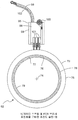
도 11a에서, 캔틸레버형 스프링이, US 2014/0045348 A1의 도 12a에 도시된 브러시 홀더와 유사한, 개조 브러시 홀더로 교체되었다. 이를 위하여, 브러시 홀더는 고정자 위에 설치되도록 구성되고, 브러시 블록(98)과 도통하는 도선(96)을 구비하며, 브러시 블록은 다시 튜브(99)에 대해 수직 미끄럼 이동을 하도록 설치된다. 브러시 블록은 브러시 블록과 튜브 사이에서 작용하는 니게이터 스프링(100)에 의해 하방으로 이동하도록 편위되어 있다. In Fig. 11A, the cantilevered spring was replaced with a modified brush holder similar to the brush holder shown in Fig. 12A of US 2014/0045348 A1. To this end, the brush holder is configured to be mounted on the stator and has a lead 96 conducting with the
각각 101로 지시되는 다수의 섬유 브러시 조립체가 브러시 블록과 함께 이동하도록 브러시 블록 위에 설치되어 있다. 각각의 브러시 조립체는 섬유 다발을 포함한다. 브러시 다발의 상측 주변 단부는 브러시 튜브 내에 수용되어 유지되고, 다발의 하측 주변 단부는 브러시 튜브 아래에서 하방으로 연장된다. 브러시 다발 내의 개별 섬유들은 회전자 위의 링에 계합되는 팁 내의 최하측 단부에서 종료된다. 니게이터 스프링의 주된 기능은 실질적으로 동일한 힘으로 브러시 홀더를 하방으로 움직이도록 압박하여 마모를 보상하는 것이다.A plurality of fiber brush assemblies, each designated 101, are mounted on the brush block to move with the brush block. Each brush assembly includes a fiber bundle. The upper peripheral edge of the brush bundle is received and held within the brush tube, and the lower peripheral edge of the bundle extends downward below the brush tube. The individual fibers in the brush bundle terminate at the lowermost end in the tip that engages the ring on the rotor. The main function of the nigator spring is to press the brush holder downward with substantially equal force to compensate for wear.
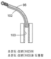
도 11a에 도시된 브러시 홀더는, 초전도 리본(102)이 도선(96)과 평행하게 배치되고 브러시 블록이 그 중앙에 초전도 리본(103)을 구비하는 점에서 US 2014/0045348 A1에 도시된 것과 다르다. 도 11b에 가장 잘 도시된 바와 같이, 리본(102)은 리본(103)과 도통한다.The brush holder shown in Fig. 11A differs from that shown in US 2014/0045348 A1 in that the
앞에서와 같이, 전체 슬립-링이 적당한 극저온 유체에 잠겨서 초전도 리본들을 그 전이 온도들 미만으로 냉각시키도록 구성되어 있다.As before, the entire slip-ring is immersed in a suitable cryogenic fluid to cool the superconducting ribbons to below their transition temperatures.
도 11a에서, 각각의 다발 내의 섬유들은 적당한 은/구리 합금으로 형성될 수 있고, US 2014/0045348 A1에서 교시된 바와 같이 여러 다발들의 하측 주변 단부가 환형일 수 있다.In Fig. 11A, the fibers in each bundle may be formed of a suitable silver / copper alloy, and the lower peripheral end of the bundles may be annular, as taught in US 2014/0045348 A1.
니게이터 스프링 및 캔틸레버 스프링의 원측 단부에 설치되는 FOT 브러시 조립체를 구비한 초전도 슬립-링(도 12)A superconducting slip-ring (FIG. 12) with an FOT brush assembly mounted at one end of the nigator spring and the cantilever spring,
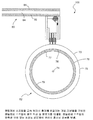
도 12a는 대체로 105로 지시되는 슬립-링 조립체의 다른 형태를 개략적으로 도시한 도면이다.12A schematically illustrates another form of the slip-ring assembly generally indicated at 105. In this embodiment,
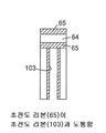
도 12a에서, 도 11에 도시된 도선(96)은 제거되었다. 대신, 브러시 홀더가 앞에서 설명한 바와 같이 스프링 조립체(63)의 원측 단부 위에 설치되는 것으로 도시되어 있다. 도 12b는 하부 리본965)가 브러시 홀더 위의 초전도 리본(103)과 도통하는 것을 나타내고 있다. In Fig. 12A, the
여기서 다시, 전체 장치가 적당한 극저온 유체에 잠겨서 여러 초전도 재료들을 그 전이 온도들 미만으로 냉각시키도록 구성되어 있다.Here again, the entire device is configured to be submerged in a suitable cryogenic fluid to cool several superconducting materials below their transition temperatures.
개조예들Modifications Examples
본 발명은 많은 변경들과 개조들이 행해질 수 있음이 예상된다.It is anticipated that many modifications and adaptations of the present invention may be made.
여기서 언급된 바와 같이, 본 발명의 원리는 팬케익형 슬립-링 및 드럼형 슬립-링 둘 다에 적용될 수 있고 또한 호모폴라 모터 또는 호모폴라 발전기에 적용될 수 있다. 브러시 다발들은 종래 기술에서와 같이 압축될 수도 있고 또는 US 2014/0045348 A1에서 교시된 바와 같이 환형일 수도 있다. 섬유들의 팁들은 캔틸레버 설치형 스프링 조립체에 의해, 니게이터 스프링에 의해 또는 어떤 다른 수단에 의해 회전자 링에 압박될 수 있다.As mentioned herein, the principles of the present invention can be applied to both pancake type slip-ring and drum type slip-ring and also to homopolar motor or homopolar generators. The brush bundles may be compressed as in the prior art or may be annular as taught in US 2014/0045348 A1. The tips of the fibers may be pressed against the rotor ring by a cantilevered spring assembly, by a nigger spring, or by some other means.
본 발명의 본질은, 장치의 특정 부분들이 초전도 재료들로 만들어지고 이에 따라 전체 장치가 액체 질소와 같은 극저온 유체에 잠겨서 초전도 재료들을 각각의 전이 온도들 미만으로 냉각시킬 수 있는, 회전자 링과의 개선된 FOT 접촉을 제공하는 데 있다. 이러한 현상이 일어날 때, 초전도 재료들의 저항은 실질적으로 영일 것이다. The essence of the present invention is that the specific parts of the device are made of superconducting materials so that the entire device can be immersed in a cryogenic fluid such as liquid nitrogen to cool the superconducting materials below their respective transition temperatures And to provide improved FOT contact. When this happens, the resistance of the superconducting materials will be substantially zero.
따라서 본 발명은 전류를 미끄럼 접촉 계면으로 그리고 미끄럼 접촉 계면으로부터 이동시키는 초전도 리본들의 사용과 관련된다. 높은 전류 밀도 용량 때문에, FOT 브러시들은 전류가 낮은 접촉 저항으로 초전도 리본들 내에서 흐르게 하도록 구성될 수 있다. 낮은 접촉 저항은 초전도 슬립-링 및 호모폴라 모터에 대해 극히 중요한 인자이다. 접촉 저항을 낮출수록 액체 질소가 덜 소비된다.The present invention thus relates to the use of superconducting ribbons that move currents from and to sliding contact interfaces. Because of the high current density capability, the FOT brushes can be configured to allow current to flow in the superconducting ribbons with a low contact resistance. Low contact resistance is a critical factor for superconducting slip-ring and homo-polar motors. The lower the contact resistance, the less liquid nitrogen is consumed.
초전도 리본들은 폭이 1/2인치일 수 있고 임계 전류(/C)가 307암페어일 수 있다. 임계 전류(/C)는 자체장(self-field)이 초전도 상태가 무너지게 하는 전류 레벨이다. (자료: US 2014/0045348 A1 published February 13, 2014)The superconducting ribbons may be 1/2 inch in width and the threshold current (/ C ) may be 307 amperes. The critical current (/ C ) is the current level at which the self-field collapses the superconducting state. (Source: US 2014/0045348 A1 published February 13, 2014)
"캔틸레버 스프링이 기계적 불안정성 때문에 작업하기 어렵다는 것이 알려져 있다. (예컨대, Shobert, Erle; Carbon Brushes: The Physics and Chemistry of Sliding Contacts; Chapter 4, FIG. 4.7, "Mechanical Considerations in Brushes and Collectors"; (1965); at p.87. 참조) 브러시가 한 방향으로 움직임에 따라 스프링 힘을 제거하고 다른 방향으로는 스프링 힘을 증가시키는 방식으로 스프링이 진동할 수 있으면 캔틸레버-스프링 브러시들 상에서 "떨림 소음(chattter)"이 일어날 수 있다. *** 이 떨림 소음은 (1) 브러시를 가능한 한 짧게 유지하고; (2) 부하를 받을 때 스프링이 실질적으로 직선이 되도록 스프링을 설계하고; 그리고 (3) 도 4:7b에 도시된 바와 같이 스프링을 테이퍼지게 하는 것에 의해 최소화될 수 있다. 스프링을 테이퍼지게 하면 자연 주기가 공진 진동을 위해 사용될 수 있는 가능성이 감소된다."It is known that cantilever springs are difficult to work due to mechanical instability (see, for example, Shobert, Erle, Carbon Brushes: The Physics and Chemistry of Sliding Contacts, Chapter 4, FIG. 4.7," Mechanical Considerations in Brushes and Collectors " If the spring can vibrate in such a way as to remove the spring force as the brush moves in one direction and increase the spring force in the other direction, the "chatter" (2) designing the spring so that the spring is substantially straight when receiving the load; and (3) as shown in Figure 4 Can be minimized by tapering the spring as shown in Figure 7b: tapering the spring allows for the possibility that the natural period can be used for resonant vibration .
또한, 캔틸레버 스프링은 브러시 마모(x)에 따라 브러시 힘(F)이 감소되고 궁극적으로 모든 전기적 요건들을 충족시키기 위해 요구되는 최소 수직력에 의해 브러시의 수명이 제한되는 문제를 가지고 있다. 적절한 브러시 힘이 없다면, 신호 브러시들은 허용 가능한 전기 소음 레벨에서 작동하지 않을 것이고 전력 브러시들에는 전기 아크가 발생할 수 있다. 이는 수백만 인치의 링 주행이 가능한 브러시에 대한 주된 인자이다. 니게이터 스프링은 브러시의 수명 내내 정해진 변위 범위에서 실질적으로 일정한 힘을 유지하고, 이에 따라 브러시의 수명은 브러시 마모에 따라 힘이 감소하는 것에 의해 제한되지 않는다. 또한, 니게이터 스프링은 고유한 감쇄 메커니즘을 제공하고 이에 따라 브러시 스프링 "떨림 소음"이 제거된다."In addition, the cantilever spring has a problem that the brush force F is reduced in accordance with the brush wear (x), and the life of the brush is limited by the minimum normal force required to satisfy all the electrical requirements ultimately. Without proper brushing force, the signal brushes will not operate at acceptable electrical noise levels and electrical brushes may generate electrical arcing. This is a major factor for brushes capable of ringing millions of inches. The nigator spring maintains a substantially constant force within a defined displacement range over the lifetime of the brush, so that the life of the brush is not limited by the force decreasing with brush wear. In addition, the nigger spring provides a unique damping mechanism, thereby eliminating the brush spring "trembling noise ".
본 발명은 슬립-링 및 드럼형 전기자 호모폴라 모터를 위한 모든 컴포넌트들(즉, 브러시-스프링들의 양측면 및 링의 내경부)에 초전도 리본들을 부착하는 것을 포함한다. 브러시-스프링의 각각의 측면에 초전도 리본들을 부착하면 전류 용량이 증가될 뿐만 아니라 브러시-스프링의 움직임이 안정되어 실온으로부터 액체 질소 온도까지 변할 때 브러시 힘의 변화가 최소화된다. 도 11a, 도 11b, 도 12a 및 도 12b에 도시된 바와 같은 니게이터 스프링 구성이 사용될 때, 브러시 홀더와 니게이터 스프링이 넓은 온도 범위에 걸쳐서 자유롭게 움직이도록 공차가 허용되어야만 한다. 니게이터 스프링은 넓은 범위의 브러시 마모에 걸쳐 브러시에 일정한 힘을 가하는 장점을 갖는다. 리본들은 디스크-전기자 호모폴라 모터의 양면에 부착될 수 있다. 리본들이 초전도 상태로 전이될 때, 리본들 내의 전기 저항은 영으로 떨어지고, 임계 전류가 초과될 때까지 전류는 저항 없이 흐른다. 브러시 내의 섬유들에 리본들을 부착하는 것은 실용적이지 않다.The present invention involves attaching superconducting ribbons to all components (i. E., Both sides of the brush-springs and the inner diameter of the ring) for a slip-ring and drum type armature homopolar motor. Attaching superconducting ribbons to each side of the brush-spring not only increases the current capacity but also minimizes the change in brush force when the brush-spring movement is stable and varies from room temperature to liquid nitrogen temperature. When the nigger spring configuration as shown in Figs. 11A, 11B, 12A and 12B is used, the tolerance must be allowed such that the brush holder and the nigger spring can freely move over a wide temperature range. The nigator spring has the advantage of applying a constant force to the brush over a wide range of brush wear. Ribbons can be attached to both sides of the disc-armature homopolar motor. When the ribbons transition to the superconducting state, the electrical resistance in the ribbons drops to zero, and the current flows without resistance until the threshold current is exceeded. It is not practical to attach the ribbons to the fibers in the brush.
FOT 브러시들과 초전도 슬립-링들에 대해 최근 연구가 행해졌다. 드럼형 슬립-링은 입력 양극 브러시 및 링과 출력 음극 브러시 및 링으로 구성되었다(도 5 참조). 각각의 다발 내의 섬유들은 그 공칭 직경이 약 0.003인치이고 섬유당 최대 전류 밀도는 약 1769A/in2이다. 1,200개의 0.003" 직경 섬유들을 구비하는 단일 FOT 브러시에 대해 측정된 전류 밀도는 21,230A/in2이었다(도 6 참조). 추가 브러시들 및 링 쌍들은 비례하는 최대 전류 밀도를 운반하도록 구성될 수 있다(표 7 참조). Recent research has been done on FOT brushes and superconducting slip-rings. The drum type slip-ring consisted of an input positive electrode brush and ring and an output negative electrode brush and ring (see FIG. 5). The fibers in each bundle have a nominal diameter of about 0.003 inches and a maximum current density per fiber of about 1769 A / in < 2 & gt ;. The measured current density for a single FOT brush with 1,200 0.003 "diameter fibers was 21,230 A / in 2 (see Figure 6). Additional brushes and ring pairs can be configured to carry a proportional maximum current density (See Table 7).
브러시 다발 내의 섬유들의 수가 증가함에 따라, 소망하는 브러시 컴플라이언스를 달성하도록 브러시 중앙의 개구 직경을 증가시키는 것과 섬유들의 자유 길이를 조정하는 것을 고려해야만 한다.As the number of fibers in the brush bundle increases, one must consider increasing the opening diameter at the center of the brush and adjusting the free length of the fibers to achieve the desired brush compliance.
팬케익형 슬립-링이 도 7에 도시되어 있다. 이러한 기하학적 구조에 의해 초전도 리본이 각각의 링의 내경부 및 외경부 위에 위치되고 이에 따라 드럼형 슬립-링과 비교하여 전류 용량이 배가되게 된다. 추가 브러시가 각각의 스프링에 부가되었고, 이에 의해 이제 브러시들의 전류 용량이 증가되어 각각의 링 위의 추가 리본을 보상한다.A pancake type slip-ring is shown in Fig. This geometry allows the superconducting ribbon to be positioned on the inner and outer diameter portions of each ring, thereby doubling the current capacity as compared to the drum type slip-ring. An additional brush has been added to each spring, thereby increasing the current capacity of the brushes to compensate for the additional ribbon on each ring.
도 6에 제시된 데이터에 기초하면, 링 당 두 개의 브러시들 및 스프링들이 있으면 전류 용량은 360암페어 규모일 것이고, 링 당 네 개의 브러시들이 있으면 전류 용량은 720암페어 규모일 것이다. 리본들이 각각의 링의 내경부 및 외경부 위에 있는 경우 614암페어의 복합 전류 용량을 가질 것이다. 따라서 이러한 배치 형태에 대한 제한 인자는 브러시가 아니다.Based on the data presented in Fig. 6, if there are two brushes and springs per ring, the current capacity will be 360 amps, and if there are four brushes per ring, the current capacity will be 720 amps. And will have a composite current capacity of 614 amperes if the ribbons are on the inside and outside diameter of each ring. Therefore, the limiting factor for this type of layout is not a brush.
따라서, 개선된 장치들의 다수의 형태들과 실시예들이 도시되고 설명되었으며 이에 대한 몇 개의 개조예들이 구체적으로 논의되었지만, 통상의 기술자는 다음의 특허청구범위에 의해 한정되고 구별되는 본 발명의 기술적 사상의 범위를 벗어나지 않으면서 다양한 부가적인 변경과 개조가 행해질 수 있음을 쉽게 알 것이다.Thus, although numerous forms and embodiments of the improved devices have been shown and described and several modifications have been discussed in detail, it will be understood by those of ordinary skill in the art that various changes in form and detail may be made therein without departing from the spirit and scope of the invention as defined by the following claims It will be readily understood that various additional modifications and adaptations may be made without departing from the scope of the invention.
Claims (27)
상기 고정자 위에 설치되고, 서로 반대측인 두 개의 표면을 각각 구비하는, 적어도 두 개의 전류-운반 브러시-스프링;
각각의 브러시-스프링 위에 설치되는 적어도 하나의 섬유 브러시 조립체로서, 각각의 브러시 조립체가 섬유들의 다발을 구비하고, 상기 섬유들의 팁들이 상기 연관된 회전자 링에 계합되어 상기 고정자와 상기 연관된 회전자 링 사이에서 전류를 전달하도록 된, 적어도 하나의 섬유 브러시 조립체;
각각의 브러시-스프링의 반대측 표면들에 설치되고 상기 고정자를 연관된 브러시-스프링 위에 설치된 각각의 브러시 조립체와 도통시키는 초전도 재료로 된 리본; 및
상기 회전자 링들의 내경부들에 설치되는 초전도 재료로 된 다른 리본을 포함하고,
상기 장치의 전기 저항이 실질적으로 영으로 감소되고 상기 장치의 전류 전달 능력이 증가되도록, 상기 초전도 재료들의 전이 온도들 미만의 온도인 극저온 유체에 상기 장치가 잠기는 것을 특징으로 하는 장치.An apparatus configured to provide electrical contact between a stator and two rotor rings,
At least two current-carrying brush-springs mounted on the stator and each having two surfaces opposite to each other;
At least one fiber brush assembly mounted on a respective brush-spring, wherein each brush assembly has a bundle of fibers, the tips of the fibers being engaged with the associated rotor ring to form a gap between the stator and the associated rotor ring At least one fiber brush assembly adapted to deliver electrical current to the fiber brush assembly;
A ribbon of superconducting material installed on opposite surfaces of each brush-spring and conducting said stator to respective brush assemblies mounted on associated brush-springs; And
And another ribbon of superconducting material disposed on inner diameters of the rotor rings,
Characterized in that the device is immersed in a cryogenic fluid at a temperature below the transition temperatures of the superconducting materials so that the electrical resistance of the device is substantially reduced to zero and the current carrying capacity of the device is increased.
상기 극저온 유체의 절연 내력이 공기의 절연 내력의 약 20배인 것을 특징으로 하는 장치.The method according to claim 1,
Wherein the dielectric strength of said cryogenic fluid is about 20 times the dielectric strength of air.
상기 초전도 재료들이 동일한 것을 특징으로 하는 장치.The method according to claim 1,
Wherein the superconducting materials are identical.
상기 극저온 유체가 액체 질소인 것을 특징으로 하는 장치.The method according to claim 1,
Wherein said cryogenic fluid is liquid nitrogen.
각각의 브러시-스프링 위에 설치되는 리본들이 각각의 브러시-스프링 위에 고정되는 것을 특징으로 하는 장치.The method according to claim 1,
Characterized in that the ribbons to be mounted on the respective brush-springs are fixed on the respective brush-springs.
각각의 브러시-스프링 위에 설치되는 리본들이 각각의 브러시-스프링 위에 솔더링되는 것을 특징으로 하는 장치.The method of claim 5,
Wherein the ribbons provided on each brush-spring are soldered onto respective brush-springs.
상기 장치가 상기 극저온 유체의 온도까지 냉각될 때 각각의 브러시-스프링에 의해 연관된 브러시 조립체에 가해지는 힘이 각각의 브러시-스프링 위에 설치된 초전도 리본들에 의해 영향을 받지 않도록 각각의 브러시-스프링 위에 설치되는 리본들이 구성되고 배치되는 것을 특징으로 하는 장치.The method of claim 6,
When the device is cooled to the temperature of the cryogenic fluid, the force exerted by the respective brush-spring on the associated brush assembly is set on the respective brush-spring so that it is not affected by the superconducting ribbons installed on the respective brush- ≪ / RTI > are arranged and arranged.
각각의 브러시-스프링 위에 설치되는 리본들은 그 크기가 동일한 것을 특징으로 하는 장치.The method of claim 7,
Characterized in that the ribbons provided on each brush-spring are the same in size.
각각의 브러시 조립체가 브러시 튜브를 포함하고, 연관된 섬유 다발의 한 주변 단부가 상기 브러시 튜브 내에 수용되는 것을 특징으로 하는 장치.The method according to claim 1,
Wherein each brush assembly includes a brush tube and one peripheral end of the associated fiber bundle is received within the brush tube.
각각의 브러시 튜브의 일부를 둘러싸고 브러시 튜브 너머로 연장하는 집속기 튜브(collimator tube)를 더 포함하고, 상기 회전자가 상기 고정자에 대해 회전할 때 연관된 다발 내의 상기 섬유들의 하측 주변 단부들의 가로 방향 움직임을 제한하도록 상기 집속기 튜브의 하측 단부가 구성되는 것을 특징으로 하는 장치.The method of claim 9,
Further comprising a collimator tube surrounding a portion of each brush tube and extending beyond the brush tube to limit lateral movement of the lower peripheral ends of the fibers in an associated bundle as the rotor rotates relative to the stator Wherein the lower end of the inlet tube is configured to allow the outlet of the outlet tube to be closed.
각각의 집속기 튜브가 연관된 브러시 튜브 위에 조정 가능하게 설치되는 것을 특징으로 하는 장치.The method of claim 10,
Each of the concentrator tubes being adjustably mounted on an associated brush tube.
각각의 브러시 튜브 아래로 연장하는 섬유들이 환형이도록 각각의 브러시 튜브 아래에 있는 상기 섬유들의 중앙부가 제거된 것을 특징으로 하는 장치.The method of claim 11,
Wherein the central portion of the fibers under each brush tube is removed such that the fibers extending under each brush tube are annular.
상기 장치가 슬립-링인 것을 특징으로 하는 장치.The method according to claim 1,
Characterized in that the device is a slip-ring.
상기 장치가 호모폴라 모터인 것을 특징으로 하는 장치.The method according to claim 1,
Characterized in that the device is a homopolar motor.
상기 장치가 호모폴라 발전기인 것을 특징으로 하는 장치.The method according to claim 1,
Characterized in that the device is a homo-polar generator.
상기 다발 내의 섬유들은 그 공칭 직경이 약 0.003인치이고 섬유당 최대 전류 밀도는 약 1769A/in2인 것을 특징으로 하는 장치.The method according to claim 1,
Wherein the fibers in the bundle have a nominal diameter of about 0.003 inches and a maximum current density per fiber of about 1769 A / in < 2 & gt ;.
회전자를 제공하는 단계;
상기 회전자 위에 금 링을 제공하는 단계;
은/구리 섬유들의 다발을 구비하는 브러시 조립체를 제공하는 단계;
상기 금속 섬유들의 팁들이 상기 회전자 링에 계합되도록 각각의 브러시 조립체를 상기 고정자 위에 설치하는 단계;
상기 브러시 조립체들을 극저온 유체에 잠기게 하는 단계; 및
상기 회전자 링으로부터 상기 섬유들의 팁들로 금이 이전되도록 상기 회전자를 상기 섬유 팁들에 대해 이동시키는 단계를 포함하고,
이에 의해 상기 회전자 링과 상기 섬유들의 팁들 사이에 금-대-금의 미끄럼 전기 접촉을 제공하는 것을 특징으로 하는 방법.A method of providing sliding electrical contact of a gold-to-gold alloy between a rotor ring and tips of a plurality of metal fibers disposed in a brush assembly disposed on the stator,
Providing a rotor;
Providing a gold ring over the rotor;
Providing a brush assembly having a bundle of silver / copper fibers;
Installing respective brush assemblies on the stator such that tips of the metal fibers are engaged with the rotor ring;
Immersing the brush assemblies in a cryogenic fluid; And
Moving the rotor relative to the fiber tips such that gold is transferred from the rotor ring to the tips of the fibers,
Thereby providing sliding electrical contact of gold-to-gold between the rotor ring and the tips of the fibers.
상기 회전자가 드럼형 슬립-링, 팬케익형 슬립-링, 디스크-전기자형 호모폴라 모터 또는 디스크-전기자형 호모폴라 발전기의 부품이고, 상기 회전자 링이 상기 회전자의 외부 표면 위에 구비되는 것을 특징으로 하는 방법.18. The method of claim 17,
Characterized in that the rotor is a part of a drum-type slip-ring, a pancake slip-ring, a disk-armature homo-polar motor or a disk-armature homo-polar generator and the rotor ring is provided on the outer surface of the rotor Lt; / RTI >
반대측인 표면들을 구비하는 전류-운반 브러시-스프링을 제공하는 단계;
초전도 재료로 된 리본들을 제공하는 단계;
상기 초전도 재료로 된 리본을 상기 브러시-스프링의 반대측 표면들 각각의 위에 설치하는 단계;
상기 브러시-스프링의 근측 단부를 상기 고정자 위에 설치하는 단계; 및
상기 고정자가 상기 브러시-스프링과 상기 리본들을 통해 상기 브러시 조립체와 도통하도록 상기 브러시 조립체를 상기 브러시-스프링의 원측 주변 단부 위에 설치하는 단계를 더 포함하는 것을 특징으로 하는 방법.18. The method of claim 17,
Providing a current-carrying brush-spring having opposing surfaces;
Providing ribbons of superconducting material;
Providing a ribbon of superconducting material on each of opposite surfaces of the brush-spring;
Providing a proximal end of the brush-spring on the stator; And
Further comprising the step of installing the brush assembly on the distal peripheral edge of the brush-spring such that the stator is in communication with the brush assembly through the brush-spring and the ribbons.
초전도 재료로 된 다른 리본을 제공하는 단계; 및
이러한 다른 리본을 상기 회전자 링의 내경부 위에 설치하는 단계를 더 포함하는 것을 특징으로 하는 방법.The method of claim 19,
Providing another ribbon of superconducting material; And
Further comprising the step of providing such another ribbon on the inner diameter portion of the rotor ring.
상기 극저온 유체는 그 온도가 상기 초전도 재료의 전이 온도보다 낮은 것을 특징으로 하는 방법.The method of claim 19,
Wherein the temperature of the cryogenic fluid is lower than the transition temperature of the superconducting material.
상기 극저온 유체는 그 온도가 이러한 다른 초전도 재료의 전이 온도보다 낮은 것을 특징으로 하는 방법.18. The method of claim 17,
Wherein the temperature of the cryogenic fluid is lower than the transition temperature of the other superconducting material.
상기 회전자 링을 상기 섬유 팁들에 대해 이동시키는 단계가 상기 회전자 링을 상기 섬유 팁들에 대해 회전시키는 단계를 포함하는 것을 특징으로 하는 방법.18. The method of claim 17,
Wherein moving the rotor ring relative to the fiber tips comprises rotating the rotor ring about the fiber tips.
상기 금속 섬유들의 팁들을 약 200g의 힘으로 상기 회전자 링에 대해 편위시키는 단계를 더 포함하는 것을 특징으로 하는 방법.18. The method of claim 17,
Further comprising deflecting the tips of the metal fibers against the rotor ring with a force of about 200 grams.
적어도 두 개의 금 링을 구비하는 회전자;
고정자;
상기 고정자 위에 설치되는 근측 단부들 및 상기 회전자 링들 중 연관된 한 회전자 링 가까이에 배치되는 원측 단부들을 구비하는 스프링 조립체들로서, 각각의 스프링 조립체가 초전도 재료를 포함하는 스프링 조립체들;
각각의 스프링 조립체의 원측 주변 단부 위에 설치되는 적어도 하나의 브러시 조립체로서, 각각의 브러시 조립체가 브러시 홀더와 다발로 배치되는 다수의 은/구리 금속 섬유를 구비하고, 상기 다발의 한 주변 단부가 연관된 브러시 홀더 내에 배치되고, 상기 다발의 반대측 단부는 연관된 회전자 링에 계합되는 다수의 섬유 팁들에서 종료되는, 적어도 하나의 브러시 조립체를 포함하며,
초전도 재료의 온도가 그 전이 온도 미만으로 감소되도록 상기 슬립-링이 극저온 유체에 잠기고,
상기 은/구리 섬유들의 팁들이 금으로 덮이고,
이에 의해 상기 슬립-링이 상기 섬유들의 팁들과 상기 회전자 링 사이에 금-대-금의 미끄럼 접촉을 갖는 것을 특징으로 하는 슬립-링.As a slip-ring,
A rotor having at least two gold rings;
Stator;
Spring assemblies having proximal ends mounted on the stator and distal ends disposed adjacent an associated one of the rotor rings, each spring assembly comprising a superconducting material;
At least one brush assembly mounted on a distal peripheral end of each spring assembly, wherein each brush assembly has a plurality of silver / copper metal fibers arranged in a bundle with the brush holder, and one peripheral end of the bundle is connected to an associated brush Wherein at least one brush assembly is disposed within the holder and the opposite end of the bundle terminates in a plurality of fiber tips engaged with an associated rotor ring,
The slip-ring is immersed in the cryogenic fluid such that the temperature of the superconducting material is reduced below its transition temperature,
The tips of the silver / copper fibers are covered with gold,
Whereby the slip-ring has a gold-to-gold sliding contact between the tips of the fibers and the rotor ring.
적어도 하나의 금 링을 구비하는 회전자;
고정자;
적어도 하나의 스프링 조립체로서, 각각의 스프링 조립체가 상기 고정자 위에 설치되는 근측 단부 및 연관된 회전자 링 가까이에 배치되는 원측 단부를 구비하고 그리고 초전도 재료를 포함하는 적어도 하나의 스프링 조립체들;
각각의 스프링 조립체의 원측 주변 단부 위에 설치되는 적어도 하나의 브러시 조립체로서, 각각의 브러시 조립체가 브러시 홀더와 다발로 배치되는 다수의 은/구리 금속 섬유를 구비하고, 상기 다발의 한 주변 단부가 연관된 브러시 홀더 내에 배치되고, 상기 다발의 반대측 단부는 연관된 회전자 링에 계합되는 다수의 섬유 팁들에서 종료되는, 적어도 하나의 브러시 조립체를 포함하며,
초전도 재료의 온도가 그 전이 온도 미만으로 감소되도록 상기 호모폴라 모터가 극저온 유체에 잠기고,
상기 은/구리 섬유들의 팁들이 금으로 덮이고,
이에 의해 상기 호모폴라 모터가 섬유들의 팁들과 상기 회전자 링 사이에 금-대-금의 미끄럼 접촉을 갖는 것을 특징으로 하는 호모폴라 모터.As a homopolar motor,
A rotor having at least one gold ring;
Stator;
At least one spring assembly comprising: at least one spring assembly, each spring assembly having a proximal end disposed on the stator and a distal end disposed proximate the associated rotor ring and comprising a superconducting material;
At least one brush assembly mounted on a distal peripheral end of each spring assembly, wherein each brush assembly has a plurality of silver / copper metal fibers arranged in a bundle with the brush holder, and one peripheral end of the bundle is connected to an associated brush Wherein at least one brush assembly is disposed within the holder and the opposite end of the bundle terminates in a plurality of fiber tips engaged with an associated rotor ring,
The homo-polar motor is immersed in the cryogenic fluid so that the temperature of the superconducting material is reduced below its transition temperature,
The tips of the silver / copper fibers are covered with gold,
Whereby the homopolar motor has a gold-to-gold sliding contact between the tips of the fibers and the rotor ring.
적어도 하나의 금 링을 구비하는 회전자;
고정자;
적어도 하나의 스프링 조립체로서, 각각의 스프링 조립체가 상기 고정자 위에 설치되는 근측 단부 및 연관된 회전자 링 가까이에 배치되는 원측 단부를 구비하고 그리고 초전도 재료를 포함하는 적어도 하나의 스프링 조립체들;
각각의 스프링 조립체의 원측 주변 단부 위에 설치되는 적어도 하나의 브러시 조립체로서, 각각의 브러시 조립체가 브러시 홀더와 다발로 배치되는 다수의 은/구리 금속 섬유를 구비하고, 상기 다발의 한 주변 단부가 연관된 브러시 홀더 내에 배치되고, 상기 다발의 반대측 단부는 연관된 회전자 링에 계합되는 다수의 섬유 팁들에서 종료되는, 적어도 하나의 브러시 조립체를 포함하며,
초전도 재료의 온도가 그 전이 온도 미만으로 감소되도록 상기 호모폴라 발전기가가 극저온 유체에 잠기고,
상기 은/구리 섬유들의 팁들이 금으로 덮이고,
이에 의해 상기 호모폴라 발전기가 섬유들의 팁들과 상기 회전자 링 사이에 금-대-금의 미끄럼 접촉을 갖는 것을 특징으로 하는 호모폴라 발전기.As homopolar generators,
A rotor having at least one gold ring;
Stator;
At least one spring assembly comprising: at least one spring assembly, each spring assembly having a proximal end disposed on the stator and a distal end disposed proximate the associated rotor ring and comprising a superconducting material;
At least one brush assembly mounted on a distal peripheral end of each spring assembly, wherein each brush assembly has a plurality of silver / copper metal fibers arranged in a bundle with the brush holder, and one peripheral end of the bundle is connected to an associated brush Wherein at least one brush assembly is disposed within the holder and the opposite end of the bundle terminates in a plurality of fiber tips engaged with an associated rotor ring,
The homo-polar generator is immersed in the cryogenic fluid so that the temperature of the superconducting material is reduced below its transition temperature,
The tips of the silver / copper fibers are covered with gold,
Whereby the homo-polar generator has a gold-to-gold sliding contact between the tips of the fibers and the rotor ring.
Applications Claiming Priority (1)
| Application Number | Priority Date | Filing Date | Title |
|---|---|---|---|
| PCT/US2014/061111 WO2016060682A1 (en) | 2014-10-17 | 2014-10-17 | Superconducting devices, such as slip-rings and homopolar motors/generators |
Publications (1)
| Publication Number | Publication Date |
|---|---|
| KR20170067896A true KR20170067896A (en) | 2017-06-16 |
Family
ID=51845537
Family Applications (1)
| Application Number | Title | Priority Date | Filing Date |
|---|---|---|---|
| KR1020177013367A KR20170067896A (en) | 2014-10-17 | 2014-10-17 | Superconducting devices, such as slip-rings and homopolar motors/generators |
Country Status (8)
| Country | Link |
|---|---|
| US (2) | US10446995B2 (en) |
| EP (1) | EP3207626B1 (en) |
| JP (1) | JP6531169B2 (en) |
| KR (1) | KR20170067896A (en) |
| CN (1) | CN107408785B (en) |
| CA (1) | CA2964853A1 (en) |
| IL (1) | IL251743A0 (en) |
| WO (1) | WO2016060682A1 (en) |
Cited By (1)
| Publication number | Priority date | Publication date | Assignee | Title |
|---|---|---|---|---|
| KR102358089B1 (en) * | 2021-08-06 | 2022-02-08 | 정호균 | Pin type wire for slip ring |
Families Citing this family (7)
| Publication number | Priority date | Publication date | Assignee | Title |
|---|---|---|---|---|
| US11495932B2 (en) * | 2017-06-09 | 2022-11-08 | Applied Materials, Inc. | Slip ring for use in rotatable substrate support |
| CN108551064A (en) * | 2018-04-26 | 2018-09-18 | 陕西旋星电子科技有限公司 | Fiber brush bundle slip ring assembly |
| CN109639064B (en) * | 2018-12-30 | 2023-10-13 | 浙江联宜电机有限公司 | End face brush end cover rotor assembly auxiliary device |
| CN111232294B (en) * | 2020-01-09 | 2021-06-11 | 东华大学 | Automatic device and method for bundling metal filaments |
| KR102362583B1 (en) * | 2021-06-04 | 2022-02-15 | 연합정밀주식회사 | Slip ring assembly |
| CN113794079B (en) * | 2021-07-30 | 2022-08-16 | 中南大学 | 1000-kilometre long-life multipoint end-face contact silver alloy fiber electric brush and preparation method thereof |
| CN114597726B (en) * | 2022-03-17 | 2023-05-23 | 淮阴师范学院 | Conductive wheel of superconducting thin film preparation equipment and operation method thereof |
Family Cites Families (45)
| Publication number | Priority date | Publication date | Assignee | Title |
|---|---|---|---|---|
| DE2944065A1 (en) * | 1979-10-31 | 1981-05-14 | Siemens AG, 1000 Berlin und 8000 München | POWER TRANSFER BRUSH WITH GRAPHITE FILMS |
| FR2469813A1 (en) * | 1979-11-08 | 1981-05-22 | France Etat | MULTI-FILAMENTARY BROOM SLIDING ELECTRIC CONTACT DEVICE |
| US4398113A (en) | 1980-12-15 | 1983-08-09 | Litton Systems, Inc. | Fiber brush slip ring assembly |
| JPS6110084U (en) | 1984-06-22 | 1986-01-21 | 株式会社日立製作所 | Superconducting rotating electric machine |
| US4602177A (en) * | 1984-12-20 | 1986-07-22 | Westinghouse Electric Corp. | Homopolar generators with thermosyphons for improved cooling |
| JPS6450745A (en) | 1987-08-19 | 1989-02-27 | Hitachi Ltd | Single pole rotary electric machine |
| US4938282A (en) | 1988-09-15 | 1990-07-03 | Zohler Steven R | High performance heat transfer tube for heat exchanger |
| MY110330A (en) | 1991-02-13 | 1998-04-30 | Furukawa Electric Co Ltd | Heat-transfer small size tube and method of manufacturing the same |
| US5375654A (en) | 1993-11-16 | 1994-12-27 | Fr Mfg. Corporation | Turbulating heat exchange tube and system |
| US5415225A (en) | 1993-12-15 | 1995-05-16 | Olin Corporation | Heat exchange tube with embossed enhancement |
| US5408152A (en) | 1994-03-28 | 1995-04-18 | Westinghouse Electric Corporation | Method of improving heat transfer in stator coil cooling tubes |
| JPH0874862A (en) | 1994-09-06 | 1996-03-19 | Hitachi Ltd | Solid lubricating bearing |
| JPH08128793A (en) | 1994-10-28 | 1996-05-21 | Toshiba Corp | Heat transfer tube with internal fins and manufacture thereof |
| CA2179448A1 (en) | 1995-07-12 | 1997-01-13 | Atsuyumi Ishikawa | Heat exchanger for refrigerating cycle |
| US5791405A (en) | 1995-07-14 | 1998-08-11 | Mitsubishi Shindoh Co., Ltd. | Heat transfer tube having grooved inner surface |
| US5599615A (en) * | 1995-11-09 | 1997-02-04 | Xerox Corporation | High performance electric contacts |
| US6245440B1 (en) | 1996-04-05 | 2001-06-12 | University Of Virginia | Continuous metal fiber brushes |
| JP2833589B2 (en) | 1996-07-31 | 1998-12-09 | 日本電気株式会社 | Resin sealing molding apparatus and resin sealing method for semiconductor device |
| AU742180B2 (en) | 1997-01-29 | 2001-12-20 | Dieter W. Blum | Dynamo-electric machines and control and operating system for the same |
| US6006826A (en) | 1997-03-10 | 1999-12-28 | Goddard; Ralph Spencer | Ice rink installation having a polymer plastic heat transfer piping imbedded in a substrate |
| US6903484B1 (en) * | 1999-04-23 | 2005-06-07 | Doris Kuhlmann-Wilsdorf | Fluidic pressure holder for electrical metal fiber and foil brushes and ancillary cables |
| US6800981B2 (en) * | 2001-04-30 | 2004-10-05 | Hipercon, Llc | Tubular brush holder |
| US6700297B2 (en) * | 2001-06-01 | 2004-03-02 | Ut-Battelle, Llc | Superconducting PM undiffused machines with stationary superconducting coils |
| US20030052564A1 (en) | 2001-07-09 | 2003-03-20 | Doris Wilsdorf | Bipolar machines-a new class of homopolar motor/generator |
| US7423359B2 (en) | 2004-06-18 | 2008-09-09 | Moog Inc. | Fluid-dispensing reservoir for large-diameter slip rings |
| US7495366B2 (en) | 2004-06-18 | 2009-02-24 | Moog Inc. | Compact slip ring incorporating fiber-on-tips contact technology |
| US7105983B2 (en) * | 2004-06-18 | 2006-09-12 | Moog Inc. | Electrical contact technology and methodology for the manufacture of large-diameter electrical slip rings |
| US20080048513A1 (en) | 2004-06-29 | 2008-02-28 | Doris Wilsdorf | Multipolar-Plus Machines-Multipolar Machines With Reduced Numbers of Brushes |
| US7557485B1 (en) * | 2004-10-08 | 2009-07-07 | The United States Of America As Represented By The Secretary Of The Navy | Ion conducting electrolyte brush additives |
| US20060186371A1 (en) | 2005-02-22 | 2006-08-24 | Roy Perlove | Heat exchange fluid with coloring agent |
| US7226893B2 (en) | 2005-02-23 | 2007-06-05 | Superpower, Inc. | Superconductive articles having density characteristics |
| US7463914B2 (en) | 2005-06-08 | 2008-12-09 | Dynamo Capital, Inc. | Superconducting acyclic homopolar electromechanical power converter |
| KR100760993B1 (en) * | 2006-03-15 | 2007-09-21 | 한국전기연구원 | Lamination joining apparatus and method of superconducting coated conductor |
| US20070278093A1 (en) * | 2006-06-02 | 2007-12-06 | Barnard Michael P | Electrical conductive contact ring for electroplating or electrodeposition |
| DE102006058259A1 (en) | 2006-12-08 | 2008-06-19 | Kludi Gmbh & Co. Kg | Flat siphon for washstand or sink, comprises pipe body closed at its one end or bypasses into deflecting elbow and upper partition is arranged within tubing cross section of pipe body and lower partition is spaced axial to upper partition |
| US8189317B2 (en) * | 2007-04-23 | 2012-05-29 | Illinois Tool Works Inc. | Grounding brush system for mitigating electrical current on rotating shafts |
| CN100547339C (en) | 2008-03-12 | 2009-10-07 | 江苏萃隆精密铜管股份有限公司 | A kind of intensify heat transfer pipe and preparation method thereof |
| KR100981049B1 (en) | 2008-09-11 | 2010-09-10 | 두산중공업 주식회사 | Apparatus for cooling current leads of a superconducting rotating machine |
| US8078242B2 (en) | 2009-04-15 | 2011-12-13 | Dynamo Capital, Inc. | Internal impedance converting superconducting acyclic power converter |
| CN201533223U (en) | 2009-11-03 | 2010-07-21 | 中山大洋电机股份有限公司 | Electric brush assembly of motor and applied motor thereof |
| CA2836183A1 (en) | 2011-05-17 | 2012-11-22 | Heron Energy Pte Ltd | Low speed electromagnetic turbine |
| JP5775785B2 (en) | 2011-10-06 | 2015-09-09 | 株式会社フジクラ | Oxide superconducting wire and method for producing the same |
| WO2013125812A1 (en) | 2012-02-24 | 2013-08-29 | Doosan Heavy Industries & Construction Co., Ltd. | Superconducting rotating electrical machine and manufacturing method for high temperature superconducting film thereof |
| JP6046796B2 (en) * | 2012-03-13 | 2016-12-21 | ムーグ インコーポレーテッド | Improved advanced fiber contact design brush assembly |
| CN104332795B (en) | 2014-09-26 | 2017-02-01 | 中南大学 | Metal fiber brush and preparation method thereof |
-
2014
- 2014-10-17 WO PCT/US2014/061111 patent/WO2016060682A1/en active Application Filing
- 2014-10-17 US US15/500,423 patent/US10446995B2/en not_active Expired - Fee Related
- 2014-10-17 CN CN201480083581.8A patent/CN107408785B/en not_active Expired - Fee Related
- 2014-10-17 EP EP14792956.6A patent/EP3207626B1/en active Active
- 2014-10-17 JP JP2017520514A patent/JP6531169B2/en not_active Expired - Fee Related
- 2014-10-17 CA CA2964853A patent/CA2964853A1/en not_active Abandoned
- 2014-10-17 KR KR1020177013367A patent/KR20170067896A/en active IP Right Grant
-
2017
- 2017-04-14 IL IL251743A patent/IL251743A0/en unknown
-
2019
- 2019-09-03 US US16/559,018 patent/US10965077B2/en active Active
Cited By (1)
| Publication number | Priority date | Publication date | Assignee | Title |
|---|---|---|---|---|
| KR102358089B1 (en) * | 2021-08-06 | 2022-02-08 | 정호균 | Pin type wire for slip ring |
Also Published As
| Publication number | Publication date |
|---|---|
| US10965077B2 (en) | 2021-03-30 |
| CA2964853A1 (en) | 2016-04-21 |
| WO2016060682A1 (en) | 2016-04-21 |
| CN107408785B (en) | 2020-03-03 |
| US20170250512A1 (en) | 2017-08-31 |
| EP3207626A1 (en) | 2017-08-23 |
| EP3207626B1 (en) | 2021-06-02 |
| JP6531169B2 (en) | 2019-06-12 |
| JP2017538386A (en) | 2017-12-21 |
| US20200144778A1 (en) | 2020-05-07 |
| IL251743A0 (en) | 2017-06-29 |
| US10446995B2 (en) | 2019-10-15 |
| CN107408785A (en) | 2017-11-28 |
Similar Documents
| Publication | Publication Date | Title |
|---|---|---|
| US10965077B2 (en) | Superconducting devices, such as slip-rings and homopolar motors/generators | |
| JP2017538386A5 (en) | ||
| US9362697B2 (en) | Fiber-on-tip contact design brush assemblies | |
| JP4366424B2 (en) | Electrical contact techniques and methods for making large diameter electrical slip rings | |
| US7423359B2 (en) | Fluid-dispensing reservoir for large-diameter slip rings | |
| US8437819B2 (en) | Superconductor cable | |
| DE3006330C2 (en) | ||
| RU2608386C2 (en) | High-speed turbine | |
| US5451825A (en) | Voltage homopolar machine | |
| EP1902511B1 (en) | Superconducting acyclic homopolar electromechanical power converter | |
| EP1898500B1 (en) | Compact slip ring incorporating fiber-on-tips contact technology | |
| Oswald et al. | Reluctance motors with bulk HTS material | |
| US2788456A (en) | Conductor-ventilated generators | |
| Johnson et al. | High-current brushes, part IV: machine environment tests | |
| Safdarzadeh et al. | Measuring of electrical currents, voltage and resistance of an axial bearing | |
| McNab et al. | High-current density carbon fiber brush experiments in humidified air and helium | |
| Lewis et al. | Friction, wear, and noise of slip ring and brush contacts for synchronous satellite use | |
| Santoro et al. | Brushless slip ring for high power transmission | |
| Slepian | High-current brushes, part V: subdivided monolithic Brushes at very high-current levels | |
| Buskens | The Effect of Bending on the Critical Current of ReBCO Based Stack Cables: High Magnetic Fields for Muon Collider. | |
| Michal | Theoritical and Experimental Determination of the Magnetic Blast Field due to the Current Flow in the Electrodes | |
| CN111725680A (en) | Rolling reversing device | |
| McNab et al. | Homopolar Motor and Brush Development Studies |
Legal Events
| Date | Code | Title | Description |
|---|---|---|---|
| A201 | Request for examination | ||
| E902 | Notification of reason for refusal | ||
| E701 | Decision to grant or registration of patent right |