KR20170054596A - Binary-pulse converting device for communication and signal transmission device using thereof - Google Patents
Binary-pulse converting device for communication and signal transmission device using thereof Download PDFInfo
- Publication number
- KR20170054596A KR20170054596A KR1020150156424A KR20150156424A KR20170054596A KR 20170054596 A KR20170054596 A KR 20170054596A KR 1020150156424 A KR1020150156424 A KR 1020150156424A KR 20150156424 A KR20150156424 A KR 20150156424A KR 20170054596 A KR20170054596 A KR 20170054596A
- Authority
- KR
- South Korea
- Prior art keywords
- pulse
- signal
- quartic
- communication
- binary
- Prior art date
Links
- 238000004891 communication Methods 0.000 title claims abstract description 26
- 230000008054 signal transmission Effects 0.000 title description 3
- 238000007493 shaping process Methods 0.000 claims abstract description 4
- 238000000034 method Methods 0.000 claims description 7
- 239000002096 quantum dot Substances 0.000 claims 1
- 230000002238 attenuated effect Effects 0.000 abstract description 7
- 239000010453 quartz Substances 0.000 abstract description 7
- VYPSYNLAJGMNEJ-UHFFFAOYSA-N silicon dioxide Inorganic materials O=[Si]=O VYPSYNLAJGMNEJ-UHFFFAOYSA-N 0.000 abstract description 7
- 230000000694 effects Effects 0.000 abstract description 5
- 238000006243 chemical reaction Methods 0.000 description 7
- 238000010586 diagram Methods 0.000 description 6
- 230000005540 biological transmission Effects 0.000 description 4
- 238000001228 spectrum Methods 0.000 description 2
- 238000005516 engineering process Methods 0.000 description 1
- 238000011084 recovery Methods 0.000 description 1
- 230000003595 spectral effect Effects 0.000 description 1
Images


Classifications
-
- H—ELECTRICITY
- H04—ELECTRIC COMMUNICATION TECHNIQUE
- H04L—TRANSMISSION OF DIGITAL INFORMATION, e.g. TELEGRAPHIC COMMUNICATION
- H04L25/00—Baseband systems
- H04L25/02—Details ; arrangements for supplying electrical power along data transmission lines
- H04L25/03—Shaping networks in transmitter or receiver, e.g. adaptive shaping networks
- H04L25/03828—Arrangements for spectral shaping; Arrangements for providing signals with specified spectral properties
- H04L25/03834—Arrangements for spectral shaping; Arrangements for providing signals with specified spectral properties using pulse shaping
-
- H—ELECTRICITY
- H03—ELECTRONIC CIRCUITRY
- H03K—PULSE TECHNIQUE
- H03K5/00—Manipulating of pulses not covered by one of the other main groups of this subclass
- H03K5/01—Shaping pulses
-
- H—ELECTRICITY
- H04—ELECTRIC COMMUNICATION TECHNIQUE
- H04L—TRANSMISSION OF DIGITAL INFORMATION, e.g. TELEGRAPHIC COMMUNICATION
- H04L25/00—Baseband systems
- H04L25/02—Details ; arrangements for supplying electrical power along data transmission lines
- H04L25/08—Modifications for reducing interference; Modifications for reducing effects due to line faults ; Receiver end arrangements for detecting or overcoming line faults
Landscapes
- Engineering & Computer Science (AREA)
- Physics & Mathematics (AREA)
- Power Engineering (AREA)
- Computer Networks & Wireless Communication (AREA)
- Signal Processing (AREA)
- Nonlinear Science (AREA)
- Spectroscopy & Molecular Physics (AREA)
- Dc Digital Transmission (AREA)
Abstract
본 발명은 기저대역신호를 펄스 정형함에 있어서, 위상이 급격히 변화하는 부분에서 발생되는 고주파성분을 감쇠시켜 주파수영역에서 사이드로브(sidelobe)가 급격히 감쇠되도록 하고, 이로 인하여 인접 채널간의 간섭효과를 최소화함으로써, 전송대역폭이 감소하여 전송효율이 개선되어 신호의 송수신처리를 보다 원활하게 수행할 수 있도록 해 주는 통신용 2진 펄스 변환장치 및 이를 이용한 신호 송신장치에 관한 것이다.
본 발명에 따른 통신용 2진 펄스 변환장치 및 이를 이용한 신호 송신장치는 데이터 신호에 대한 기저대역 신호를 생성하는 신호 처리부와, 상기 신호 처리부로부터 제공되는 기저대역신호를 "쿼틱(Quartic) 펄스"형태의 신호로 변환하는 쿼틱 펄스 변환부 및, 상기 쿼틱 펄스 변환부로부터 제공되는 쿼틱 펄스를 변조처리하는 신호 변조부를 포함하여 구성되고, 상기 쿼틱 펄스(s(t))는 위상이 반전되는 부분에 대해 기울기가 "0"인 신호로, 다음의 수학식을 만족하도록 구성되는 것을 특징으로 한다. 이때, 쿼틱 펄스(s(t))에 대한 수학식은 
A communication binary pulse converting apparatus and a signal transmitting apparatus using the same according to the present invention include a signal processor for generating a baseband signal for a data signal and a baseband signal provided from the signal processor for a quartic pulse And a signal modulator for modulating a quartz pulse provided from the quartic pulse converter, wherein the quartic pulse s (t) has a slope with respect to a portion where the phase is inverted, Is "0 ", the following equation is satisfied. At this time, the equation for the quartic pulse s (t)
Description
본 발명은 기저대역신호를 펄스 정형함에 있어서, 위상이 급격히 변화하는 부분에서 발생되는 고주파성분을 감쇠시켜 주파수영역에서 사이드로브(sidelobe)가 급격히 감쇠되고, 이로 인하여 인접 채널간의 간섭효과를 최소화함으로써, 전송효율을 개선시켜 신호의 송수신처리를 보다 원활하게 수행할 수 있도록 해 주는 통신용 2진 펄스 변환장치 및 이를 이용한 신호 송신장치에 관한 것이다.In the pulse shaping of a baseband signal, a sidelobe is rapidly attenuated in a frequency domain by attenuating a high-frequency component generated in a portion where a phase is rapidly changed, thereby minimizing an interference effect between adjacent channels, And more particularly, to a communication binary pulse conversion apparatus and a signal transmission apparatus using the same.
일반적으로 통신 시스템에서는 기저대역신호(baseband signal)로서 사각형상의 구형파 펄스가 주로 사용되고 있다. Generally, in a communication system, a square wave pulse of a rectangular shape is mainly used as a baseband signal.
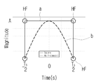
도1에는 통신시스템에서 이용되는 구형파 펄스(a)의 형태가 도시되어 있다. 즉, 통신 시스템에서는 2진 데이터의 "1"과 "0"에 상응하여 구형파 펄스의 양(+)과 음(-)의 형태로 기저대역신호를 전송한다.FIG. 1 shows a form of a square wave pulse a used in a communication system. That is, in the communication system, the baseband signal is transmitted in the form of positive (+) and negative (-) square wave pulses corresponding to "1" and "0" of binary data.
그런데, 상기한 구형파 펄스(a)는 신호의 크기 변화가 급격하여 고주파 성분을 많이 포함하고 있기 때문에, 인접 채널 간의 간섭으로 인하여 수신시 데이터의 복원에 오류가 발생되는 단점이 있다. 도1에서 "HF" 고주파 성분을 포함하는 부분을 나타낸다.However, the square wave pulse (a) has a disadvantage in that an error occurs in data recovery upon reception due to interference between adjacent channels, because the signal amplitude varies rapidly and includes many high-frequency components. Quot; HF "high frequency component in FIG.
도1에 도시된 구형파 펄스(a)를 이용하여 통신 시스템을 구현하는 경우, 구형파 펄스(a)가 고주파성분을 많이 포함하고 있기 때문에 주파수대역폭 효율측면에서 비효율적이다. When a communication system is implemented using the rectangular wave pulse (a) shown in FIG. 1, the square wave pulse (a) contains a lot of high frequency components, which is inefficient in terms of frequency bandwidth efficiency.
한편, 상기한 구형파 펄스(a)를 이용하여 기저대역신호를 전송하는 경우 발생되는 문제를 해결하기 위하여 도1에서 반주기-사인파(half-sinusoid) 형태의 펄스(b)를 이용하여 기저대역신호를 전송하는 방법이 제안되었다.In order to solve the problem caused when the baseband signal is transmitted using the square wave pulse (a), a half-sinusoidal pulse (b) is used to generate a baseband signal A method of transmitting is proposed.
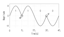
도2는 도1에 도시된 반주기-사인파(b)를 이용한 기저대역신호를 예시한 도면으로, 도2에는 "1100" 데이터 스트림이 도시되어 있다. FIG. 2 is a diagram illustrating a baseband signal using the half-sine wave (b) shown in FIG. 1, and FIG. 2 shows a data stream of "1100 ".
그러나, 상기한 반주기-사인파 펄스(도1의 b)는 사각형상의 구형파 펄스(도1의 a)에 비해 주파수 영역에서 사이드 로브(sidelobe)가 빠르게 감쇠되기 때문에 인접 채널간의 간섭이 감소하는 장점은 있으나, 도2에 도시된 바와 같이 위상이 180°반전되는 부분, 즉 "HF" 부분에서의 고주파성분은 여전히 남아있게 된다. However, since the sidelobe is rapidly attenuated in the frequency domain as compared with the square-shaped rectangular pulse (a in Fig. 1), the half-sine pulse (b in Fig. 1) , The high frequency component in the portion where the phase is inverted by 180 degrees, i.e., the "HF" portion still remains as shown in Fig.
이는 결국 통신시스템에서 기저대역신호의 고주파성분을 줄인다면, 주파수영역에서의 사이드로브의 급격한 감쇠는 실제 전송하는 점유대역폭을 감소시켜 스펙트럼 효율을 개선시킬 수 있음을 의미하는 것으로, 이를 위해서는 송신단에서 기저대역신호로서 고주파성분을 감소시킬 수 있는 알맞은 형태의 신호가 요구된다. This means that if the high frequency component of the baseband signal is reduced in the communication system, the sudden attenuation of the side lobe in the frequency domain means that the occupied bandwidth actually transmitted can be reduced to improve the spectral efficiency. A suitable type of signal capable of reducing the high frequency component is required as the band signal.
이에, 본 발명은 상기한 사정을 감안하여 창출된 것으로, 신호의 위상이 급격히 반전되는 부분에 대해서는 기울기를 "0"으로 만드는 새로운 형태의 2진 펄스를 제공함으로써, 기저대역신호의 고주파성분을 감소시켜 인접 채널간의 간섭효과를 최소화함은 물론, 전송효율 또한 개선시킬 수 있는 통신용 2진 펄스 변환장치 및 이를 이용한 신호 송신장치를 제공함에 그 기술적 목적이 있다. Accordingly, the present invention has been made in view of the above circumstances, and it is an object of the present invention to provide a new type of binary pulse which makes the slope to "0" for a portion where the phase of the signal is rapidly inverted, thereby reducing the high frequency component of the baseband signal The present invention has been made in view of the above problems, and it is an object of the present invention to provide a communication binary conversion apparatus and a signal transmission apparatus using the same for minimizing interference effects between adjacent channels and improving transmission efficiency.
상기 목적을 달성하기 위한 본 발명의 일측면에 따르면, 데이터 신호에 대응되는 통신용 2진 펄스를 생성하는 통신용 2진 펄스 변환장치에 있어서, 데이터 신호를 "쿼틱(Quartic) 펄스"형태의 신호로 변환하도록 구성되는 것을 특징으로 하는 쿼틱 펄스 변환장치가 제공된다.According to an aspect of the present invention, there is provided a communication binary pulse conversion apparatus for generating a communication binary pulse corresponding to a data signal, the apparatus comprising: a data conversion unit for converting a data signal into a signal of a "quartic pulse & A quartz pulse conversion device is provided.
또한, 상기 쿼틱 펄스는 1주기 신호에 대해 중앙부와 양단부의 기울기가 "0"인 형태인 것을 특징으로 하는 통신용 2진 펄스 변환장치가 제공된다.The binary pulse conversion apparatus for communication is characterized in that the quartic pulse has a shape in which the slope of the central part and both ends is "0" with respect to the one-period signal.
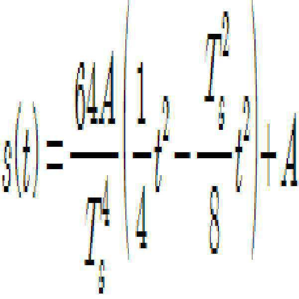
또한, 상기 쿼틱 펄스(s(t))는 다음의 수학식을 만족하는 것을 특징으로 하는 통신용 2진 펄스 변환장치가 제공된다. 
또한, 상기 쿼틱 펄스는 "-Ts/2 ~ +Ts/2" 의 펄스 주기에서 위상이 반전되는 부분은 "-Ts/2" 인 지점과 "0"인 지점 및 "+Ts/2"인 지점인 것을 특징으로 하는 통신용 2진 펄스 변환장치가 제공된다.In addition, the quartic pulse has a phase inverted portion in the pulse cycle of "-Ts / 2 to + Ts / 2", a point at which the phase is "-Ts / 2", a point at "0" And a binary-signal converting unit for converting the binary signal into a binary signal.
또한, 상기 목적을 달성하기 위한 본 발명의 또 다른 일측면에 따르면, 데이터 신호인 기저대역신호를 생성하는 신호 처리부와, 상기 신호 처리부로부터 제공되는 기저대역신호를 "쿼틱(Quartic) 펄스" 로 정형화하여 출력하는 쿼틱 펄스 변환부 및, 상기 쿼틱 펄스 변환부로부터 제공되는 쿼틱 펄스로 정형화된 기저대역신호를 변조처리하는 신호 변조부를 포함하여 구성되고, 상기 쿼틱 펄스(s(t))는 위상이 반전되는 부분의 기울기가 "0"인 신호로, 다음의 수학식을 만족하도록 구성되는 것을 특징으로 하는 신호 송신장치. 
또한, 상기 쿼틱 펄스는 1주기 신호에 대해 중앙부와 양단부의 기울기가 "0"인 형태인 것을 특징으로 하는 신호 송신장치가 제공된다.Further, the quartic pulse is characterized in that the slope of the central part and the both ends of the 1-period signal is "0 ".
본 발명에 의하면 기저대역신호에 대해 위상이 급격히 변화하는 지점에 대해서는 기울기가 "0"으로 설정되는 쿼틱 펄스를 생성하여 송신하도록 함으로써, 급격한 위상변화 부분의 제거로 고주파 성분을 감쇠시킴으로써, 인접 채널간 간섭을 최소화할 수 있게 된다.According to the present invention, by generating and transmitting a quasi-pulse whose slope is set to "0 " at a point where the phase is abruptly changed with respect to the baseband signal, by abruptly removing the phase change portion and attenuating the high- Interference can be minimized.
또한, 시간영역에서 본 발명에 따른 쿼틱 펄스의 폭이 기존 통신용 2진 펄스형태의 구형파 및, 반주기 사인파에 비해 좁음으로 인해 주파수영역에서의 메인로브(mainlobe)는 넓어지나, 사이드로브가 급격히 감쇠하게 되므로, 통신시스템에서 한정적 자원인 주파수 대역폭을 효율적으로 사용하는 것이 가능하여 결과적으로 전송효율을 개선시킬 수 있게 된다. In addition, since the width of the quasi-pulse according to the present invention in the time domain is narrower than that of the conventional communication binary pulse type and the half sine wave, the mainlobe in the frequency domain is widened but the side lobe is rapidly attenuated Therefore, it is possible to efficiently use the frequency bandwidth as a limited resource in the communication system, and as a result, the transmission efficiency can be improved.
도1은 통신시스템에서 이용되는 구형파 펄스와 반주기-사인파 펄스를 도시한 도면.
도2는 데이터 스트림 "1100"에 대하여 반주기-사인파 펄스에서 고주파성분들이 여전히 남아있는 부분들을 예시한 도면.
도3은 본 발명에 따른 송신장치의 구성을 개략적으로 도시한 도면.
도4는 도3 도시된 쿼틱 펄스 변환부(200)에서 생성되는 통신용 2진 펄스 즉, 쿼틱(Quartic) 펄스를 도시한 도면.
도5는 데이터 스트림 "1100"에 대하여 생성된 쿼틱 펄스 스트림을 예시한 도면.
도6 및 도7은 종래 통신용 2진 펄스와 본 발명에 따른 쿼틱 펄스의 특성을 비교한 도면.1 shows a square wave pulse and a half-sine wave pulse used in a communication system;
Figure 2 illustrates portions where high frequency components still remain in the half-sine wave pulse for the data stream "1100 ".
3 schematically shows a configuration of a transmitting apparatus according to the present invention.
FIG. 4 is a diagram illustrating a communication binary pulse, that is, a quartic pulse, generated by the
5 illustrates a quartic pulse stream generated for a data stream "1100 ".
FIGS. 6 and 7 are diagrams comparing characteristics of a conventional binary pulse for communication and a quasi-pulse according to the present invention; FIG.
본 발명에 관한 설명은 구조적 내지 기능적 설명을 위한 실시예에 불과하므로, 본 발명의 권리범위는 본문에 설명된 실시예에 의하여 제한되는 것으로 해석되어서는 아니 된다. 즉, 실시예는 다양한 변경이 가능하고 여러 가지 형태를 가질 수 있으므로 본 발명의 권리범위는 기술적 사상을 실현할 수 있는 균등물들을 포함하는 것으로 이해되어야 한다. 또한, 본 발명에서 제시된 목적 또는 효과는 특정 실시예가 이를 전부 포함하여야 한다거나 그러한 효과만을 포함하여야 한다는 의미는 아니므로, 본 발명의 권리범위는 이에 의하여 제한되는 것으로 이해되어서는 아니 될 것이다.The description of the present invention is merely an example for structural or functional explanation, and the scope of the present invention should not be construed as being limited by the embodiments described in the text. That is, the embodiments are to be construed as being variously embodied and having various forms, so that the scope of the present invention should be understood to include equivalents capable of realizing technical ideas. Also, the purpose or effect of the present invention should not be construed as limiting the scope of the present invention, since it does not mean that a specific embodiment should include all or only such effect.
이하 첨부된 도면을 참조하여 본 발명에 따른 통신용 2진 펄스 변환장치 및 이를 이용한 송신장치에 대해 설명한다. DETAILED DESCRIPTION OF THE PREFERRED EMBODIMENTS Hereinafter, a communication binary pulse converting apparatus and a transmitting apparatus using the same according to the present invention will be described with reference to the accompanying drawings.
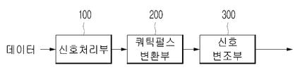
도3은 본 발명에 따른 신호 송신장치의 구성을 도시한 도면이다.3 is a diagram showing a configuration of a signal transmitting apparatus according to the present invention.
도3에 도시된 바와 같이, 신호 송신장치는 신호 처리부(100)와, 쿼틱 펄스 변환부(200), 신호 변조부(300)를 포함하여 구성된다. 3, the signal transmitting apparatus includes a
상기 신호 처리부(100)는 송신할 데이터에 대해 사각형 펄스를 이용한 기저대역신호를 생성한다. The
상기 쿼틱 펄스 변환부(200)는 상기 신호 처리부(100)로부터 제공되는 기저대역신호를 본 발명에 따른 "쿼틱(Quartic) 펄스"로 정형화하여 출력한다. "쿼틱 펄스"에 대해서는 이하에서 보다 상세히 설명한다.The
상기 신호 변조부(300)는 상기 쿼틱 펄스 변환부(200)로부터 제공되는 쿼틱 펄스로 정형화된 기저대역신호를 반송파를 이용하여 변조시킨 후 이 변조된 신호를 출력한다. The
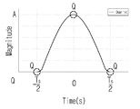
도4는 도3 도시된 쿼틱 펄스 변환부(200)에서 생성되는 통신용 2진 펄스 즉, 쿼틱(Quartic) 펄스를 도시한 도면이다.FIG. 4 is a diagram illustrating a communication binary pulse, that is, a quartic pulse, generated by the
도4에 도시된 바와 같이, 본 발명에 따른 통신용 2진 펄스는 펄스의 시작과 끝 지점 및, 중간지점의 위상이 반전되는 부분(Q)에 대해 기울기가 "0"인 "쿼틱(Quartic) 펄스"로 새롭게 정의된다.As shown in FIG. 4, the communication binary pulse according to the present invention is a quartic pulse having a slope "0" with respect to a portion (Q) where the phase of the start point and the end point of the pulse, "Is newly defined.
상기 쿼틱 펄스는 전체적으로 중앙부분이 오목하거나 볼록한 종(bell) 형상으로 된 형태로서, 1주기 신호에 대해 중앙부와 양단부의 기울기가 "0"인 형태로 구성된다. The quartz pulses are formed in the form of a concave or convex bell shape as a whole, and have a slope of "0" at the central portion and at both ends with respect to the one-period signal.
즉, 상기 쿼틱 펄스(s(t))에서 위상이 반전되는 부분(Q)은 일반적으로 "-Ts/2 ~ +Ts/2" 의 펄스 주기에서 "-Ts/2", "0", "+Ts/2" 인 부분이 된다. That is, the portion Q whose phase is inverted in the quartz pulse s (t) is generally "-Ts / 2", "0", " + Ts / 2 ".
쿼틱 펄스에서 상기한 위상 반전 지점(Q)의 기울기가 "0"인 신호(s'(t))는 수학식1과 같이 표현된다.The signal s' (t) having the slope of the above-mentioned phase inversion point Q in the quasi-pulse is "0 "

여기서, 상기 "Ts" 펄스 주기이고, 상기 "α"는 쿼틱펄스의 기울기이다. 이때, 쿼틱 펄스에서 위상 반전 지점(Q)을 제외한 다른 지점의 기울기는 알 수 없기 때문에 "α"는 임의의 값으로 설정된다. Where "T s " is the pulse period and "a" is the slope of the quasi-pulse. At this time, "?" Is set to an arbitrary value because the slope of the other point except the phase inversion point Q in the quasi-pulse is unknown.
한편, 상기 수학식 1을 적분함으로써 시간 영역에서의 신호(s'(t))를 산출할 수 있다. 이는 수학식2와 같다.On the other hand, the signal s' (t) in the time domain can be calculated by integrating Equation (1). This is shown in Equation (2).

여기서, 상기 "C"는 적분상수로서, 수학식2는 상기 ①,②,③ 식을 모두 만족하여야 한다. 따라서, 상기 수학식2의 ③식에 의해 적분상수 "C"는 "A"가 된다. 이때, 상기 수학식2 에서 "A"는 신호의 크기, 즉 진폭이 된다.Here, "C" is an integral constant, and
상기 수학식2 에 ③식을 적용하여 α값에 대해 전개하면, 수학식3과 같다.The equation (3) is applied to the equation (2) to develop the equation (3).

이어, 상기 수학식3에서 산출된 α값을 수학식2에 대입하여 전개함으로써, 위상 반전 부분의 기울기가 "0"인 쿼틱 펄스(s(t)) 산출식을 생성할 수 있다. 즉, 쿼틱 펄스(s(t))는 수학식4를 만족하는 신호가 된다.Subsequently, by substituting the α value calculated in the above-mentioned equation (3) into the equation (2), the quartic pulse s (t) calculation formula with the slope of the phase inversion part being "0" can be generated. That is, the quartic pulse s (t) becomes a signal satisfying the expression (4).
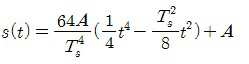
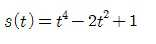
예컨대, 상기한 수학식 4에 신호의 크기인 진폭(A)가 "1"이고, 비트주기(Tb)가 "1"이며, 펄스 주기(Ts)는 "2Tb"인 경우를 적용하면, 이에 대한 쿼틱 펄스는 다음 수학식5에 의해 생성된다.For example, when the amplitude A of the signal is "1", the bit period T b is "1", and the pulse period T s is "2T b " , A quasi-pulse for this is generated by the following equation (5).
한편, 도5는 데이터 스트림 "1100"에 대하여 생성된 쿼틱 펄스 스트림을 예시한 도면으로, 도5에 도시된 바와 같이 본 발명에 따른 쿼틱 펄스 스트림은 위상이 변화되는 부분의 어떠한 포인트(Q)에서도 부드러운 변환특성을 가짐을 알 수 있다.5, a quasi-pulse stream generated for the data stream "1100 " is illustrated. As shown in FIG. 5, It can be seen that it has a smooth conversion characteristic.
도6과 도7은 종래 통신용 2진 펄스와 본 발명에 따른 쿼틱 펄스의 특성을 비교한 도면이다. FIGS. 6 and 7 are diagrams comparing characteristics of a conventional binary pulse for communication and a quasi-pulse according to the present invention.
도6에는 "-Ts/2 ~ +Ts/2" 의 펄스 주기에 대한 구형파 펄스(a)와, 반주기 사인파 펄스(b) 및, 쿼틱 펄스(c)가 도시되어 있다. 도6에 도시된 바와 같이, 본 발명에 따른 쿼틱 펄스(c)는 주파수 스펙트럼상에서 메인 로브의 펄스 폭이 구형파 펄스(a)와, 반주기 사인파 펄스(b)에 비해 좁음을 알 수 있다. 이에 따라 주파수영역에서 메인로브는 넓어질 것으로 예상할 수 있으며, 고주파성분이 집중되어 있는 부분이 제거되어 사이드로브는 더 급격히 감쇠될 것으로 예상된다. 6 shows a square wave pulse a, a half sine wave pulse b and a quasi-pulse c for a pulse period of -Ts / 2 to + Ts / 2. As shown in FIG. 6, the quartic pulse (c) according to the present invention can be seen that the pulse width of the main lobe on the frequency spectrum is narrower than that of the rectangular wave pulse (a) and the half sine wave pulse (b). Accordingly, the main lobe can be expected to be widened in the frequency domain, and the portion where high frequency components are concentrated is expected to be removed, and the side lobe is expected to be damped more rapidly.
또한, 본 발명에 따른 쿼틱 펄스(c)는 도7에 도시된 바와 같이 주파수 스펙트럼상에서 구형파 펄스(a)와, 반주기 사인파 펄스(b)에 비해 메인로브는 넓어졌으나, 사이드로브는 급격히 감쇠된 것을 확인할 수 있다. 7, the main lobe is broadened in comparison with the square wave pulse a and the half cycle sine wave pulse b in the frequency spectrum, but the side lobe is rapidly attenuated Can be confirmed.
즉, 상기 실시예에 의하면 기저대역신호를 펄스 정형함에 있어서, 위상이 급격히 변화하는 지점에 대해서는 기울기를 "0"으로 만드는 쿼틱 펄스를 생성하여 송신하도록 함으로써, 급격한 위상변화 부분에서의 고주파성분이 감쇠되고, 이로 인해 주파수영역에서의 사이드로브 역시 급격히 감쇠된다. 따라서, 인접 채널 간의 간섭을 최소화할 수 있게 되며 실제 전송대역폭 역시 감소하여 전송효율을 개선시킬 수 있게 된다. That is, according to the above embodiment, in the pulse shaping of the baseband signal, a quasi-pulse is generated and transmitted at a point where the phase is abruptly changed to "0", so that the high frequency component in the abrupt phase change portion is attenuated So that the side lobe in the frequency domain is also rapidly attenuated. Therefore, interference between adjacent channels can be minimized, and the actual transmission bandwidth is also reduced, thereby improving the transmission efficiency.
100 : 신호 처리부, 200 : 쿼틱 펄스 변환부,
300 : 신호 변조부. 100: signal processing unit, 200: quartz pulse converting unit,
300: Signal modulation section.
Claims (6)
데이터 신호를 "쿼틱(Quartic) 펄스"형태의 신호로 변환하도록 구성되는 것을 특징으로 하는 쿼틱 펄스 변환장치. A communication binary pulse converting apparatus for generating a communication binary pulse corresponding to a data signal,
And convert the data signal into a "quartic pulse" type signal.
상기 쿼틱 펄스는 1주기 신호에 대해 중앙부와 양단부의 기울기가 "0"인 형태인 것을 특징으로 하는 통신용 2진 펄스 변환장치.The method according to claim 1,
Wherein the quadrature pulse has a shape in which the slope of the central part and both ends of the 1-period signal is "0 ".
상기 쿼틱 펄스(s(t))는 다음의 수학식을 만족하는 것을 특징으로 하는 통신용 2진 펄스 변환장치.

여기서, 상기 Ts 는 펄스 주기, A 는 진폭.The method according to claim 1,
Wherein the quartic pulse (s (t)) satisfies the following equation.
Here, T s is a pulse period, A is amplitude.
상기 쿼틱 펄스는 "-Ts/2 ~ +Ts/2" 의 펄스 주기에서 위상이 반전되는 부분은 "-Ts/2" 인 지점과 "0"인 지점 및 "+Ts/2"인 지점인 것을 특징으로 하는 통신용 2진 펄스 변환장치.The method according to claim 1,
The qubit pulse is a point where the phase is inverted in the pulse cycle of "-Ts / 2 to + Ts / 2" is a point of "-Ts / 2", a point of "0" Wherein said first and second pulse-to-pulse converters are connected in parallel.
상기 신호 처리부로부터 제공되는 기저대역신호를 "쿼틱(Quartic) 펄스" 로 정형화하여 출력하는 쿼틱 펄스 변환부 및,
상기 쿼틱 펄스 변환부로부터 제공되는 쿼틱 펄스로 정형화된 기저대역신호를 변조처리하는 신호 변조부를 포함하여 구성되고,
상기 쿼틱 펄스(s(t))는 위상이 반전되는 부분의 기울기가 "0"인 신호로, 다음의 수학식을 만족하도록 구성되는 것을 특징으로 하는 신호 송신장치.
여기서, 상기 Ts 는 펄스 주기, A 는 진폭.A signal processor for generating a baseband signal for the data signal,
A quasi-pulse converter for shaping and outputting a baseband signal provided from the signal processor as a "quartic pulse"
And a signal modulator for modulating a baseband signal formatted with a quasi-pulse provided from the quartic pulse converter,
Wherein the quartic pulse s (t) is a signal having a slope of a portion where the phase is inverted to "0 ", and the following equation is satisfied.
Here, T s is a pulse period, A is amplitude.
상기 쿼틱 펄스는 1주기 신호에 대해 중앙부와 양단부의 기울기가 "0"인 형태인 것을 특징으로 하는 신호 송신장치.6. The method of claim 5,
Wherein the quadrature pulse has a shape in which a slope of a center portion and both ends of a 1-period signal is "0 ".
Priority Applications (1)
| Application Number | Priority Date | Filing Date | Title |
|---|---|---|---|
| KR1020150156424A KR101768039B1 (en) | 2015-11-09 | 2015-11-09 | Binary-pulse converting device for communication and signal transmission device using thereof |
Applications Claiming Priority (1)
| Application Number | Priority Date | Filing Date | Title |
|---|---|---|---|
| KR1020150156424A KR101768039B1 (en) | 2015-11-09 | 2015-11-09 | Binary-pulse converting device for communication and signal transmission device using thereof |
Publications (2)
| Publication Number | Publication Date |
|---|---|
| KR20170054596A true KR20170054596A (en) | 2017-05-18 |
| KR101768039B1 KR101768039B1 (en) | 2017-08-16 |
Family
ID=59049230
Family Applications (1)
| Application Number | Title | Priority Date | Filing Date |
|---|---|---|---|
| KR1020150156424A KR101768039B1 (en) | 2015-11-09 | 2015-11-09 | Binary-pulse converting device for communication and signal transmission device using thereof |
Country Status (1)
| Country | Link |
|---|---|
| KR (1) | KR101768039B1 (en) |
Family Cites Families (2)
| Publication number | Priority date | Publication date | Assignee | Title |
|---|---|---|---|---|
| KR100457819B1 (en) | 2003-02-26 | 2004-11-18 | 학교법인 한양학원 | Method and Device for generating pulse for communication |
| KR100998475B1 (en) | 2008-06-04 | 2010-12-06 | 에스케이텔레콤 주식회사 | Local wireless signal transmission apparatus and method using digital high frequency processing technology |
-
2015
- 2015-11-09 KR KR1020150156424A patent/KR101768039B1/en active IP Right Grant
Also Published As
| Publication number | Publication date |
|---|---|
| KR101768039B1 (en) | 2017-08-16 |
Similar Documents
| Publication | Publication Date | Title |
|---|---|---|
| CN111190144B (en) | Radar device and leakage correction method thereof | |
| EA031912B1 (en) | Combined amplitude-time modulation and phase modulation | |
| Popescu et al. | BPSK system on Spartan 3E FPGA | |
| CN102739590A (en) | CP-EBPSK communication system for pseudorandom sequence phase modulation and communication method thereof | |
| US9800272B2 (en) | Circuits and methods for transmitting signals | |
| WO2015176597A1 (en) | Ebpsk-based communication method and system | |
| KR20140146436A (en) | Transmitter and receiver, wireless communication method | |
| US10523489B1 (en) | Polar transmitter with zero crossing avoidance | |
| CN103346810B (en) | Full-digital direct up-conversion circuit | |
| KR101768039B1 (en) | Binary-pulse converting device for communication and signal transmission device using thereof | |
| US9397870B2 (en) | Signal receiving device for measuring characteristic of wireless communication channel, and method of measuring characteristic of wireless communication channel | |
| Saberinia et al. | N-tone sigma-delta uwb-ofdm transmitter and receiver | |
| CN101753495A (en) | Very minimum chirp keying ultra-narrow bandwidth broadcast communication modulation method | |
| JP6079825B2 (en) | Transmission / reception apparatus and transmission / reception method | |
| US8374567B2 (en) | High speed serial link with power spectral density frequency response suppression | |
| CN104618286A (en) | Strictly band-limited efficient modulating system based on impact filter forming | |
| US11310090B2 (en) | Systems, transmitters, and methods employing waveform bandwidth compression to transmit information | |
| CN104483682A (en) | S-wave band uniform measuring and control system, sidetone extraction module thereof and distance measuring tone forwarding method | |
| Bhore et al. | BPSK modulation and demodulation scheme on Spartan-3 FPGA | |
| US10700735B2 (en) | Transmission device, method thereof, and program | |
| CN103716018A (en) | Device and method for implementing digital broadband excitation source | |
| CN104980386B (en) | Method and apparatus for providing crosspoint information | |
| CN104363033B (en) | It is a kind of to use pulse modulated power line communication method | |
| CN113098436A (en) | Design method of shaping filter for PSK modulation | |
| JP5327960B2 (en) | Modulator, demodulator, communication system |
Legal Events
| Date | Code | Title | Description |
|---|---|---|---|
| PA0109 | Patent application |
Patent event code: PA01091R01D Comment text: Patent Application Patent event date: 20151109 |
|
| PA0201 | Request for examination | ||
| PE0902 | Notice of grounds for rejection |
Comment text: Notification of reason for refusal Patent event date: 20161201 Patent event code: PE09021S01D |
|
| PE0902 | Notice of grounds for rejection |
Comment text: Final Notice of Reason for Refusal Patent event date: 20170316 Patent event code: PE09021S02D |
|
| PG1501 | Laying open of application | ||
| E701 | Decision to grant or registration of patent right | ||
| PE0701 | Decision of registration |
Patent event code: PE07011S01D Comment text: Decision to Grant Registration Patent event date: 20170519 |
|
| GRNT | Written decision to grant | ||
| PR0701 | Registration of establishment |
Comment text: Registration of Establishment Patent event date: 20170808 Patent event code: PR07011E01D |
|
| PR1002 | Payment of registration fee |
Payment date: 20170808 End annual number: 3 Start annual number: 1 |
|
| PG1601 | Publication of registration | ||
| PR1001 | Payment of annual fee |
Payment date: 20220728 Start annual number: 6 End annual number: 6 |
|
| PR1001 | Payment of annual fee |
Payment date: 20240806 Start annual number: 8 End annual number: 8 |