KR20170053616A - Method and device for intermittent coating - Google Patents
Method and device for intermittent coating Download PDFInfo
- Publication number
- KR20170053616A KR20170053616A KR1020177004097A KR20177004097A KR20170053616A KR 20170053616 A KR20170053616 A KR 20170053616A KR 1020177004097 A KR1020177004097 A KR 1020177004097A KR 20177004097 A KR20177004097 A KR 20177004097A KR 20170053616 A KR20170053616 A KR 20170053616A
- Authority
- KR
- South Korea
- Prior art keywords
- nozzle
- actuator
- opening
- flexible element
- coating
- Prior art date
Links
Images


Classifications
-
- B—PERFORMING OPERATIONS; TRANSPORTING
- B05—SPRAYING OR ATOMISING IN GENERAL; APPLYING FLUENT MATERIALS TO SURFACES, IN GENERAL
- B05C—APPARATUS FOR APPLYING FLUENT MATERIALS TO SURFACES, IN GENERAL
- B05C11/00—Component parts, details or accessories not specifically provided for in groups B05C1/00 - B05C9/00
- B05C11/10—Storage, supply or control of liquid or other fluent material; Recovery of excess liquid or other fluent material
- B05C11/1047—Apparatus or installations for supplying liquid or other fluent material comprising a buffer container or an accumulator between the supply source and the applicator
-
- B—PERFORMING OPERATIONS; TRANSPORTING
- B05—SPRAYING OR ATOMISING IN GENERAL; APPLYING FLUENT MATERIALS TO SURFACES, IN GENERAL
- B05C—APPARATUS FOR APPLYING FLUENT MATERIALS TO SURFACES, IN GENERAL
- B05C5/00—Apparatus in which liquid or other fluent material is projected, poured or allowed to flow on to the surface of the work
- B05C5/02—Apparatus in which liquid or other fluent material is projected, poured or allowed to flow on to the surface of the work the liquid or other fluent material being discharged through an outlet orifice by pressure, e.g. from an outlet device in contact or almost in contact, with the work
- B05C5/0254—Coating heads with slot-shaped outlet
- B05C5/0258—Coating heads with slot-shaped outlet flow controlled, e.g. by a valve
-
- H—ELECTRICITY
- H01—ELECTRIC ELEMENTS
- H01M—PROCESSES OR MEANS, e.g. BATTERIES, FOR THE DIRECT CONVERSION OF CHEMICAL ENERGY INTO ELECTRICAL ENERGY
- H01M10/00—Secondary cells; Manufacture thereof
- H01M10/05—Accumulators with non-aqueous electrolyte
- H01M10/052—Li-accumulators
- H01M10/0525—Rocking-chair batteries, i.e. batteries with lithium insertion or intercalation in both electrodes; Lithium-ion batteries
-
- H—ELECTRICITY
- H01—ELECTRIC ELEMENTS
- H01M—PROCESSES OR MEANS, e.g. BATTERIES, FOR THE DIRECT CONVERSION OF CHEMICAL ENERGY INTO ELECTRICAL ENERGY
- H01M4/00—Electrodes
- H01M4/02—Electrodes composed of, or comprising, active material
- H01M4/04—Processes of manufacture in general
- H01M4/0402—Methods of deposition of the material
- H01M4/0404—Methods of deposition of the material by coating on electrode collectors
-
- H—ELECTRICITY
- H01—ELECTRIC ELEMENTS
- H01M—PROCESSES OR MEANS, e.g. BATTERIES, FOR THE DIRECT CONVERSION OF CHEMICAL ENERGY INTO ELECTRICAL ENERGY
- H01M4/00—Electrodes
- H01M4/02—Electrodes composed of, or comprising, active material
- H01M4/04—Processes of manufacture in general
- H01M4/0402—Methods of deposition of the material
- H01M4/0419—Methods of deposition of the material involving spraying
-
- H—ELECTRICITY
- H01—ELECTRIC ELEMENTS
- H01M—PROCESSES OR MEANS, e.g. BATTERIES, FOR THE DIRECT CONVERSION OF CHEMICAL ENERGY INTO ELECTRICAL ENERGY
- H01M4/00—Electrodes
- H01M4/02—Electrodes composed of, or comprising, active material
- H01M4/13—Electrodes for accumulators with non-aqueous electrolyte, e.g. for lithium-accumulators; Processes of manufacture thereof
- H01M4/139—Processes of manufacture
-
- H—ELECTRICITY
- H01—ELECTRIC ELEMENTS
- H01M—PROCESSES OR MEANS, e.g. BATTERIES, FOR THE DIRECT CONVERSION OF CHEMICAL ENERGY INTO ELECTRICAL ENERGY
- H01M4/00—Electrodes
- H01M4/02—Electrodes composed of, or comprising, active material
- H01M4/62—Selection of inactive substances as ingredients for active masses, e.g. binders, fillers
- H01M4/621—Binders
- H01M4/622—Binders being polymers
-
- B—PERFORMING OPERATIONS; TRANSPORTING
- B05—SPRAYING OR ATOMISING IN GENERAL; APPLYING FLUENT MATERIALS TO SURFACES, IN GENERAL
- B05C—APPARATUS FOR APPLYING FLUENT MATERIALS TO SURFACES, IN GENERAL
- B05C11/00—Component parts, details or accessories not specifically provided for in groups B05C1/00 - B05C9/00
- B05C11/10—Storage, supply or control of liquid or other fluent material; Recovery of excess liquid or other fluent material
- B05C11/1002—Means for controlling supply, i.e. flow or pressure, of liquid or other fluent material to the applying apparatus, e.g. valves
- B05C11/1034—Means for controlling supply, i.e. flow or pressure, of liquid or other fluent material to the applying apparatus, e.g. valves specially designed for conducting intermittent application of small quantities, e.g. drops, of coating material
-
- B—PERFORMING OPERATIONS; TRANSPORTING
- B05—SPRAYING OR ATOMISING IN GENERAL; APPLYING FLUENT MATERIALS TO SURFACES, IN GENERAL
- B05D—PROCESSES FOR APPLYING FLUENT MATERIALS TO SURFACES, IN GENERAL
- B05D1/00—Processes for applying liquids or other fluent materials
- B05D1/26—Processes for applying liquids or other fluent materials performed by applying the liquid or other fluent material from an outlet device in contact with, or almost in contact with, the surface
-
- B—PERFORMING OPERATIONS; TRANSPORTING
- B05—SPRAYING OR ATOMISING IN GENERAL; APPLYING FLUENT MATERIALS TO SURFACES, IN GENERAL
- B05D—PROCESSES FOR APPLYING FLUENT MATERIALS TO SURFACES, IN GENERAL
- B05D7/00—Processes, other than flocking, specially adapted for applying liquids or other fluent materials to particular surfaces or for applying particular liquids or other fluent materials
- B05D7/50—Multilayers
- B05D7/52—Two layers
- B05D7/54—No clear coat specified
- B05D7/542—No clear coat specified the two layers being cured or baked together
- B05D7/5423—No clear coat specified the two layers being cured or baked together the two layers being applied simultaneously
-
- H—ELECTRICITY
- H01—ELECTRIC ELEMENTS
- H01M—PROCESSES OR MEANS, e.g. BATTERIES, FOR THE DIRECT CONVERSION OF CHEMICAL ENERGY INTO ELECTRICAL ENERGY
- H01M10/00—Secondary cells; Manufacture thereof
- H01M10/05—Accumulators with non-aqueous electrolyte
- H01M10/052—Li-accumulators
-
- H—ELECTRICITY
- H01—ELECTRIC ELEMENTS
- H01M—PROCESSES OR MEANS, e.g. BATTERIES, FOR THE DIRECT CONVERSION OF CHEMICAL ENERGY INTO ELECTRICAL ENERGY
- H01M4/00—Electrodes
- H01M4/02—Electrodes composed of, or comprising, active material
- H01M4/04—Processes of manufacture in general
- H01M4/0402—Methods of deposition of the material
- H01M4/0414—Methods of deposition of the material by screen printing
-
- H—ELECTRICITY
- H01—ELECTRIC ELEMENTS
- H01M—PROCESSES OR MEANS, e.g. BATTERIES, FOR THE DIRECT CONVERSION OF CHEMICAL ENERGY INTO ELECTRICAL ENERGY
- H01M6/00—Primary cells; Manufacture thereof
- H01M6/40—Printed batteries, e.g. thin film batteries
-
- Y—GENERAL TAGGING OF NEW TECHNOLOGICAL DEVELOPMENTS; GENERAL TAGGING OF CROSS-SECTIONAL TECHNOLOGIES SPANNING OVER SEVERAL SECTIONS OF THE IPC; TECHNICAL SUBJECTS COVERED BY FORMER USPC CROSS-REFERENCE ART COLLECTIONS [XRACs] AND DIGESTS
- Y02—TECHNOLOGIES OR APPLICATIONS FOR MITIGATION OR ADAPTATION AGAINST CLIMATE CHANGE
- Y02E—REDUCTION OF GREENHOUSE GAS [GHG] EMISSIONS, RELATED TO ENERGY GENERATION, TRANSMISSION OR DISTRIBUTION
- Y02E60/00—Enabling technologies; Technologies with a potential or indirect contribution to GHG emissions mitigation
- Y02E60/10—Energy storage using batteries
Landscapes
- Chemical & Material Sciences (AREA)
- Engineering & Computer Science (AREA)
- Chemical Kinetics & Catalysis (AREA)
- Electrochemistry (AREA)
- General Chemical & Material Sciences (AREA)
- Manufacturing & Machinery (AREA)
- Materials Engineering (AREA)
- Coating Apparatus (AREA)
- Application Of Or Painting With Fluid Materials (AREA)
Abstract
본 발명은 장치에 대해 이송 방향(U)으로 이동하는 기질을 간헐적으로 코팅하기 위한 장치에 관한 것이며, 상기 장치는 적어도 두 개의 노즐 조들을 가진 노즐 몸체를 포함하고, 상기 노즐 조들사이에 절단부를 가진 삽입 필름이 제공되며, 상기 삽입 필름의 절단부는 상기 노즐 몸체내에서 노즐 슬롯을 형성하고, 상기 기질의 이송 방향(U)에 대해 횡 방향으로 연장되고 상기 기질에 대해 평행하게 배열된 상기 노즐 슬롯이 출구 갭에서 끝나며, 상기 출구 갭은 상기 노즐 슬롯에 의해 공급 채널과 유동 연결되고, 적어도 한 개의 노즐 조가 적어도 두 개의 개구부들을 가지며 상기 개구부들은 상기 공급 채널 및 출구 갭사이에서 직렬로 상기 노즐 슬롯속으로 형성되고, 각각의 개구부는 탄성 변형가능한 요소에 의해 상기 노즐 슬롯을 향하여 유체 밀봉 상태로 밀폐되며, 각각의 탄성 변형가능한 요소는 한쪽 측부에서 상기 노즐 슬롯내에서 코팅 물질과 작동하며 연결되고 다른 한쪽 측부에서 상기 노즐 슬롯을 향해 액츄에이터와 작동하며 연결되며, 상기 노즐 조의 개구부들이 상기 공급 채널로부터 상기 출구 갭까지 코팅 물질의 유동 방향(q)을 따라 연속적으로 배열된다.The invention relates to an apparatus for intermittently coating a substrate moving in the transport direction (U) with respect to the apparatus, the apparatus comprising a nozzle body having at least two nozzle troughs, Wherein a cutout of the insert film forms a nozzle slot in the nozzle body and the nozzle slot extends transversely with respect to the transport direction U of the substrate and is arranged parallel to the substrate, Wherein the outlet gap is in flow communication with the supply channel by the nozzle slot and wherein at least one of the nozzle troughs has at least two openings and the openings are connected in series between the supply channel and the outlet gap into the nozzle slot And each opening is sealed by a resiliently deformable element toward the nozzle slot in a fluid sealed state Wherein each resiliently deformable element is operatively connected to and operatively associated with an actuator in the nozzle slot at one side and towards the nozzle slot at the other side for operation with the coating material, (Q) of the coating material to the outlet gap.

Description
본 발명은 이동하는 기질(substrate)의 간헐적 코팅을 위한 방법 및 장치에 관한 것이다.The present invention relates to a method and apparatus for intermittent coating of a moving substrate.
일본 공개 특허 출원 제JP 2001 191 005A 호는 연속적으로 이동하는 몸체에 접착제를 간헐적으로 도포하기 위한 장치를 공개한다. 상기 문헌에는, 핫멜트(hot melt)를 노즐에 공급하여 연속적으로 이동하는 기질에 핫멜트를 도포하는 방법이 공개된다. 코팅이 생성되지 않을 때 노즐로 핫멜트의 공급이 중단되는 것이 공개된다. 이 공정을 반복함으로써, 기질이 간헐적으로 코팅된다.Japanese Laid-Open Patent Application JP 2001 191 005A discloses an apparatus for intermittently applying an adhesive to a continuously moving body. This document discloses a method of applying a hot melt to a continuously moving substrate by supplying hot melt to the nozzle. It is disclosed that the supply of hotmelt to the nozzle is interrupted when no coating is produced. By repeating this process, the substrate is intermittently coated.
선택적으로, 간헐적인 코팅은 코팅에 대한 각각의 중단작용에 의해 노즐과 기질 사이의 코팅 간격(coating gap)을 증가시켜서 형성된다. 그러나, 여전히 발생하는 코팅 물질의 지나간 흔적(wake)은 노즐 립(nozzle lip)을 젖게 하고, 따라서 기질(어레스터 필름)(arrester film)에 다시 접근될 때 과도하게 높은 개시 변부(start edge)를 초래한다.Alternatively, the intermittent coating is formed by increasing the coating gap between the nozzle and the substrate by the respective interruption action to the coating. However, the wake of the coating material that still occurs wets the nozzle lip and thus causes an excessively high start edge when approaching the substrate (arrester film) again. .
상기 방법의 또 다른 단점은 노즐의 이동 및 기질상에 습식 노즐 립의 배열이 기질내에서 진동을 야기하고, 따라서 노즐 립과 기질 사이의 이격거리에 영향을 미친다는 것이다. 따라서, 연속적인 습식 필름 두께를 달성하는 것이 불가능하다.Another disadvantage of this method is that the movement of the nozzle and the arrangement of the wet nozzle lips on the substrate causes vibrations in the substrate, thus affecting the separation distance between the nozzle lip and the substrate. Thus, it is impossible to achieve a continuous wet film thickness.
리튬 이온 2차 전지는 복수 개의 전기 화학 셀의 배열을 기초로 한다. 상기 전기 화학 셀의 전극은 각각 전기 화학 셀이 작동하는 동안 리튬 이온이 전극으로 삽입되는 활성 물질을 포함한다. 리튬 함유 산화물 화합물, 바람직하게 LiCoO2, LiFePO4, LiNi1/3Co1/3Mn1/3O2(NCM) 또는 LiNi0.8Co0.15Al0.05O2(NCA), 메조포러스 산화 티타늄(mesoporous titanium oxide)이 음의 전극(음극)에서 이용되고, 도전성 카본 블랙, 카본 블랙, 흑연 등이 양의 전극(양극)에서 이용된다.The lithium ion secondary battery is based on the arrangement of a plurality of electrochemical cells. The electrodes of the electrochemical cell each include an active material into which lithium ions are inserted into the electrode during operation of the electrochemical cell. The lithium-containing oxide compound, preferably LiCoO2, LiFePO4, LiNi1 / 3Co1 / 3Mn1 / 3O2 (NCM) or LiNi0.8Co0.15Al0.05O2 (NCA), mesoporous titanium oxide, Conductive carbon black, carbon black, graphite and the like are used in positive electrodes (positive electrodes).
문헌 제 DE 10 2004 012 476 A1호는, 적절한 코팅 물질 및 그 제조 방법을 공개하고, 상기 문헌은 본원에서 참고로 인용된다.Document DE 10 2004 012 476 A1 discloses suitable coating materials and methods for their preparation, the disclosures of which are incorporated herein by reference.
본 출원에서 제안된 코팅 방법에 의하면, 양극 및 음극의 코팅 화합물 (코팅 물질)에서 요구되는 중합체 결합제(polymer binder)는, 예를 들어 N- 메틸 피롤리 돈(N-methyl pyrrolidone)(NMP) 중의 5-10 % 플루오로 탄성 중합체 단독 중합체 또는 공중 합체에 용해되고, 폴리머 용액은 리튬과 삽입될 수 있는 금속 산화물(도전성 카본 블랙, 카본 블랙, 흑연 등)과 같은 음극으로 특정되거나 양극으로 특정된 첨가제와 혼합되어 분산된다. 이어서, 상기 분산액이 기질, 이 경우에는 전류 콜렉터(colleter) 또는 박막 코팅(film-coating)에 의해 포일, 스트립, 메쉬 등과 같은 콜렉터 몸체에 도포된다.According to the coating method proposed in the present application, the polymer binder required in the coating compound (coating material) of the positive electrode and the negative electrode is, for example, a polymer binder in N-methyl pyrrolidone (NMP) Wherein the polymer solution is dissolved in a 5-10% fluoroelastomer homopolymer or copolymer and the polymer solution is a negative electrode-specific or anodically specified additive such as a metal oxide (conductive carbon black, carbon black, graphite, etc.) ≪ / RTI > The dispersion is then applied to a collector body such as a foil, strip, mesh or the like by a substrate, in this case a current collector or film-coating.
선택적으로, 음극 측부에서 폴리 불화 비닐 리덴(polyvinylidene fluoride) 및 양극 측부에서 스티렌 부타디엔 고무(styrene butadiene rubber)를 결합제(binder)로서 이용하여 기계적 강도를 향상시키고, 도전성 카본 블랙을 제공하여 전기 전도도(electrical conductivity)를 높이는 것도 가능하다. 따라서, 활성물질이 용제를 이용하고 카르복시메틸 셀룰로오스(carboxymethyl cellulose)를 증점제(thickener)로 사용하여 페이스트(코팅 물질) 형태를 가진 금속 어레스터 재료 또는 기질에 도포된다.Alternatively, polyvinylidene fluoride on the cathode side and styrene butadiene rubber on the anode side are used as a binder to improve the mechanical strength and to provide the conductive carbon black to improve the electrical conductivity (electrical conductivity can be increased. Therefore, the active material is applied to a metal arrestor material or substrate having a paste (coating material) form using a solvent and carboxymethyl cellulose as a thickener.
다공성 미립자 층 형태(morphologies)가 가지는 낮은 전기 전도도 때문에, 도포된 전극 층(습윤 필름)은 부적절한 방출 속도 특성을 가진다. 전기적 수집 용량을 증가시키기 위해, 도전성 기질 (콜렉터 몸체, 전극)에 도포되는 도포된(applied) 전극 층은 가능한 한 얇게 만들어야 한다. 바람직하게는, 10㎛(고출력) 내지 850㎛ (고 커패시턴스)의 메니스커스(menisci)의 습윤 필름 두께가 요구된다.Because of the low electrical conductivity of the porous particulate layer morphologies, the applied electrode layer (wet film) has inadequate release rate characteristics. In order to increase the electrical collection capacity, the applied electrode layer applied to the conductive substrate (collector body, electrode) should be made as thin as possible. Preferably, a wet film thickness of menisci of 10 mu m (high power) to 850 mu m (high capacitance) is required.
슈미트(M. Schmitt) 등의 "리튬이온 전지 전극의 슬롯 다이 가공 - 코팅 윈도우 특성화(Slot-die processing of lithium-ion battery electrodes - Coating window characterization)", 화학 공학 및 가공: 프로세스 인텐시피케이션(Process Intensification), 제68권, 2013년 6월, 32-37 쪽 및 M. 슈미트 씨 등의, "리튬 이온 전지 전극의 슬롯 다이 코팅", "줄(stripe) 및 패턴 코팅에 대한 변부 효과 문제에 대한 조사", 코팅 기술 및 연구 저널, 2014년 1월, 11권 1호, 57-63쪽에 의하면, 슬롯구조의 노즐을 사용하여 포일 전극을 코팅하기 위한 방법 및 적절한 장치의 기하학적 치수와 관련하여 이 방법을 수행하기 위한 최적의 작동 조건이 설명되고 본원에서 참고한다.M. Schmitt, et al., "Slot-die processing of lithium-ion battery electrodes - Coating window characterization ", Chemical Engineering and Processing: Process Intensification Intensification, Vol. 68, June 2013, pp. 32-37 and M. Schmidt et al., "Slot die coating of lithium ion battery electrodes," " Quot; Survey ", Coating Technology and Research Journal, January 1, 2014, No. 1, No. 57-63, discloses a method for coating a foil electrode using a slotted nozzle, Lt; RTI ID = 0.0 > and / or < / RTI >
층 또는 코팅 부분에 대한 정확한 (필름) 개시 변부들 및 (필름) 단부 변부를 구하기 위해, 문헌 제 DE 10 246 327 A1 호에 의하면, 공급 채널을 차단 (폐쇄)한 후에 코팅 물질을 수축시키는 것이 이미 공지되어있다. 상기 효과를 "스너프 백(snuff-back)"이라고 한다. 차단 수단의 하류 및 유출구의 상류위치에서, 코팅 물질은 정지하고 원래의 유동방향과 반대로 음압에 의해 후방으로 이동한다.In order to find the correct (film) starting edges and (film) end edges for the layer or coating part, according to document DE 10 246 327 A1 it has already been found that shrinking the coating material after interrupting (closing) Lt; / RTI > This effect is referred to as "snuff-back ". At the downstream of the blocking means and upstream of the outlet, the coating material stops and moves backward by the negative pressure as opposed to the original flow direction.
문헌 제 US 2002/0017238 A1 호에 의하면, 간헐적인 코팅을 움직이는 기질에 도포하는 장치가 공개되고, 상기 코팅의 간헐적인 중단은 출구의 상류위치에서 스너프 백 효과와 관련하여 차단 수단에 의한 폐쇄에 의해 발생되는 것이 아니라 오히려 스너프 - 백 효과(snuff-back effect)와 관련하여 슬롯 구조의 노즐이 가지는 내부 체적의 변화에 의해 발생된다. 상기 내부 체적의 변화는 가요성 요소를 능동적으로 앞뒤로 이동시키는 노즐 조(nozzle jaws)의 조정 유닛(adjustment unit)에 의해 발생한다. 상기 능동적인 체적 증가는 흡인 효과를 유발하여 스너프 - 백 (snuff-back)이 출구 간격의 코팅 물질에 작용한다. 따라서, 코팅 물질에 존재하는 유동 방향과 전단 응력(T)의 방향이 반전된다. 기질에 도포되기 전에, 문헌 제 DE 10 246 327호에 의하면, 코팅 물질은 음압 또는 가요성 부피를 가지는 공동내에 일시적으로 저장된다. 이후 상기 저장된 코팅 물질은 후속 코팅 사이클 동안 도포된다.According to document US 2002/0017238 A1, an apparatus for applying an intermittent coating to a moving substrate is disclosed, wherein the intermittent interruption of the coating is achieved by closing by means of a blocking means associated with the snuffback effect at the upstream location of the outlet But rather is caused by a change in the internal volume of the nozzle of the slot structure in relation to the snuff-back effect. The change in the internal volume is caused by an adjustment unit of the nozzle jaws which actively moves the flexible element back and forth. The active volume increase causes a suction effect so that a snuff-back acts on the coating material at the exit gap. Thus, the flow direction present in the coating material and the direction of shear stress T are reversed. Prior to application to the substrate, according to document DE 10 246 327, the coating material is temporarily stored in a cavity having a negative pressure or a flexible volume. The stored coating material is then applied during a subsequent coating cycle.
그러나, 결과적으로, 바람직하지 않은 압력 변동 또는 압력 스파이크(pressure spikes)가 시스템내에 발생하고, 정확하게 코팅 공정이 개시될 때 결함을 발생시키는 것으로 나타났다. 압력 스파이크는 차단 수단(밸브)의 갑작스런 개방에 의해 발생한다. 공동(cavity)에 저장된 코팅 물질이 이동한(displaced) 체적 유동으로 다시 공급될 때 가요성 내부 체적의 감소는, 노즐 슬롯내에 정해지지 않은 입력 유동을 형성하게 만든다. 이것은, 상기 이동한 체적 유동이 가지는 전단 응력(T)이 상기 스너프 백 효과에 의해 방해되는(held back) 부분적인 체적 유동의 방향과 다른 방향을 가지기 때문이다. 따라서, 상기 방해되는 부분 체적 유동의 전단 응력이 가지는 방향은 변화하여 노즐 출구를 향해 충분히 높은 고정 전단 작용 또는 전단 응력을 형성한다. 따라서, 유입 유동은 충분히 현저하지 못하며, 형성된 코팅위에 불필요한 횡 방향 또는 종 방향 줄무늬들이 발생한다.However, as a result, undesirable pressure fluctuations or pressure spikes have occurred within the system and have been shown to cause defects when the coating process is accurately initiated. The pressure spike is caused by a sudden opening of the blocking means (valve). When the coating material stored in the cavity is fed back into the displaced volume flow, the reduction of the flexible inner volume causes an undefined input flow to form in the nozzle slot. This is because the shear stress T of the moved volumetric flow has a direction different from the direction of the partial volumetric flow which is held back by the snuff-back effect. Thus, the direction of shear stress of the disturbed partial volume flow changes to form a sufficiently high fixed shear action or shear stress towards the nozzle exit. Thus, the influent flow is not sufficiently significant and unnecessary transverse or longitudinal stripes occur on the formed coating.
또한, Li 이온 전지 셀을 위한 전극 층을 제조하기 위해 코팅 물질의 유동 및 가공 특성은 장치 및 방법의 구성에서 중요하다. 여기서 100,000 s-1 에 이르는 코팅 물질의 전단 속도(γ)가 형성된다. 상기 전단 속도는 인접한 두 개의 액체층들사이의 속도 차와 액체층들 사이의 이격거리의 비율로부터 계산된다. 수학적으로 상기 전단 속도는 속도 장의 구배(gradient)이다.In addition, the flow and processing characteristics of the coating material for manufacturing electrode layers for Li-ion battery cells are important in the configuration of the apparatus and method. Where the shear rate? Of the coating material to 100,000 s < -1 > is formed. The shear rate is calculated from the ratio of the velocity difference between two adjacent liquid layers to the separation distance between liquid layers. Mathematically, the shear rate is the gradient of the velocity field.
상기 코팅 물질은 가소성(pseudoplastic)을 가지거나 전단 - 시닝(shear thinning)에 따라 거동하기 때문에, 전단 속도는 본 출원에서 이용되는 코팅 물질에 대해 매우 중요하다. 따라서 체적 유량은 최소 전단 응력 Tf(유동 한계)를 초과하는 전단 응력(T)이 작용할 때에만 발생한다.Since the coating material has pseudoplastic or behaves according to shear thinning, the shear rate is very important for the coating material used in the present application. Therefore, the volumetric flow rate occurs only when a shear stress (T) exceeding the minimum shear stress Tf (flow limit) is applied.
선행 기술로에 공개된 장치의 또 다른 문제점은, 순차적인 코팅부(sequential coatings)들을 간헐적으로만 도포한다는 것이다. 복수 개의 층들을 서로 아래위에 동시에 도포하지 못한다.Another problem with the devices disclosed in the prior art is that sequential coatings are only applied intermittently. The plurality of layers can not be applied simultaneously to each other below.
따라서, 본 발명의 목적은 정확한 필름 변부를 제공하면서 일정한 습식 필름 두께를 가지며 이동 기질의 간헐적인 코팅을 제공하여 종래 기술에 공개된 문제점 및 한계를 극복하는 장치 및 방법을 제안하는 것이다.It is therefore an object of the present invention to propose an apparatus and method which overcomes the problems and limitations disclosed in the prior art by providing an intermittent coating of a moving substrate having a constant wet film thickness while providing precise film edges.
상기 목적은, 정확한 필름 개시 변부들 및 필름 단부 변부의 생산과 관련하여 상기 목적을 위해 청구항 제1항의 특징을 가지고 이동하는 기질을 간헐적으로 코팅하기 위한 장치 및 상기 목적을 위해 각각의 청구항 제5, 제6 및 제7항을 따르는 방법의 단계들에 의해 달성된다. 상기 장치 및 방법의 실시예 및 선호되는 실시예들이 종속항에 제공된다.The object is achieved by an apparatus for intermittently coating a moving substrate with the features of claim 1 for this purpose in connection with the production of precise film-starting edges and film end edges, Sixth and seventh aspects of the method of the present invention. Embodiments and preferred embodiments of the apparatus and method are provided in the dependent claims.
상기 목적을 달성하기 위해, 적어도 두 개의 노즐 조들을 가진 노즐 몸체를 포함한 장치가 제안된다. 상기 마주보는 노즐 조들사이에 절단부를 가진 삽입 필름이 제공된다. 상기 삽입 필름의 절단부는 상기 노즐 몸체내에서 노즐 슬롯을 형성한다. 상기 노즐 슬롯이 노즐 몸체의 출구 갭으로서 상기 기질의 이송 방향(U)에 대해 횡 방향으로 연장되고 상기 기질에 대해 평행하게 배열되며 끝나며, 상기 출구 갭은 상기 노즐 슬롯에 의해 공급 채널과 유동 연결된다. 적어도 한 개의 노즐 조가 적어도 두 개의 개구부들을 가지며, 상기 개구부들은 각각 커버 및 밀봉 요소와 연결된 탄성 변형가능한 요소에 의해 상기 노즐 슬롯 및 외측부를 향해 밀폐된다. 각각의 탄성 변형가능한 요소는 한쪽 측부에서 상기 노즐 슬롯내에서 코팅 물질과 연결되고 다른 한쪽 측부에서 상기 노즐 슬롯을 향해 액츄에이터와 연결된다. 상기 노즐 조의 개구부들이 상기 공급 채널로부터 상기 출구 갭까지 코팅 물질의 유동 방향(q)을 따라 연속적으로 배열된다.In order to achieve the above object, an apparatus including a nozzle body having at least two nozzle troughs is proposed. An insert film is provided having cutouts between the opposed nozzle sets. The cutting portion of the insert film forms a nozzle slot in the nozzle body. The nozzle slot extending transversely with respect to the transport direction U of the substrate as an outlet gap of the nozzle body and arranged and arranged parallel to the substrate and the outlet gap being fluidly connected with the supply channel by the nozzle slot . At least one nozzle set has at least two openings, each of which is sealed towards the nozzle slot and the outer side by an elastically deformable element associated with the cover and the sealing element, respectively. Each elastically deformable element is connected to the coating material in the nozzle slot at one side and to the actuator at the other side at the nozzle slot. The openings of the nozzle chamber are continuously arranged along the flow direction (q) of the coating material from the supply channel to the outlet gap.
청구항 제5항에 의하면, 이동하는 기질을 간헐적으로 코팅하기 위한 방법이 하기 단계들을 포함하고, 코팅 물질의 이동한 체적 유동(q)는 상기 방법의 모든 단계들에 걸쳐서 일정하게 유지된다. 코팅 물질이 펌프를 이용하여 노즐 슬롯(103)을 통해 상기 공급 채널로부터 출구 갭까지 일정한 이동 체적 유동(q)으로 이동한다. 관련 액츄에이터의 하중 또는 반대 하중을 감소시켜서 상기 출구 갭과 가장 가까운 가요성 요소가 언로딩(unloading)되고(제1 스위치 위치) 관련 액츄에이터를 반대 하중을 증가시켜서 상기 공급 채널과 가장 가까운 가요성 요소를 동시에 로딩(loading)하여(제2 스위치 위치) 상기 코팅 물질은 상기 기질에 대한 도포작용이 중단된다. 상기 액츄에이터(들)의 로딩 및 언로딩이 여기서 스위칭 상태(switching state)라고 언급되며, 각각의 스위칭 상태에서 상기 액츄에이터에 의해 상기 가요성 요소상에 가해지는 하중의 방향은 변화하지 않지만 가해지는 하중의 크기가 변화할 뿐이다. 관련 액츄에이터의 반대 하중이 증가하여 상기 출구 갭과 가장 가까운 가요성 요소가 로딩되고 관련 액츄에이터를 반대 하중을 감소시켜서 공급 채널과 가장 가까운 가요성 요소가 언로딩되어 상기 기질에 대한 상기 코팅 물질의 도포작용이 재개된다.According to claim 5, the method for intermittently coating a moving substrate comprises the following steps, and the transferred volume flow (q) of the coating material is kept constant over all steps of the method. The coating material is transferred from the supply channel to the outlet gap through the
청구항 제4항에 의하면, 이동하는 기질의 간헐적인 코팅 방법은 하기 단계들로 이루어지며, 코팅 물질들 또는 코팅 물질의 이동한 체적 유동(qa 및 qb)는 상기 방법의 모든 단계들에 걸쳐서 일정하게 유지된다. 코팅 부분들은 중첩된다.According to claim 4, an intermittent coating method of a moving substrate consists of the following steps, wherein the moving volume flows q a and q b of the coating materials or coating material are distributed over all steps of the method It remains constant. The coating portions overlap.
하나 또는 두 개의 펌프에 의해 코팅 물질 또는 코팅 물질(A,B)은 관련 공급 채널로부터 관련 노즐 슬롯을 통해 해당 출구 갭까지 이동(displaced)한다.The coating material or coating material A or B is displaced from the associated supply channel through the associated nozzle slot to the corresponding outlet gap by means of one or two pumps.
관련 액츄에이터의 반대 하중의 감소 및 각 출구 갭과 가장 가까운 가요성 요소를 동시에 언로딩하고(제1 스위치 위치), 관련 액츄에이터의 반대 하중의 증가 및 각 공급 채널과 가장 가까운 가요성 요소들을 동시에 로딩하여(제2 스위치 위치) 상기 기질에 대한 상기 코팅 물질들(A,B) 또는 코팅 물질의 도포작용이 중단된다.(First switch position), simultaneously increasing the opposing load of the associated actuator and simultaneously loading the flexible elements closest to each of the supply channels, thereby reducing the counter load of the associated actuator and simultaneously unloading the closest flexible element to each outlet gap (Second switch position), the application action of the coating materials (A, B) or the coating material to the substrate is stopped.
관련 액츄에이터의 반대 하중이 증가하여 상기 각 출구 갭과 가장 가까운 가요성 요소가 동시에 로딩되고 관련 액츄에이터의 반대 하중을 감소시켜서 공급 채널과 가장 가까운 가요성 요소가 동시에 언로딩되어 상기 기질에 대한 상기 코팅 물질들 또는 코팅 물질의 도포작용이 재개된다.The opposite loads of the associated actuators are increased so that the flexible elements closest to each of the outlet gaps are loaded simultaneously and the opposite loads of the associated actuators are reduced so that the flexible elements closest to the supply channel are simultaneously unloaded, Or the application of the coating material is resumed.
청구항 제5항에 의하면, 이동하는 기질의 간헐적인 코팅 방법은 하기 단계들로 이루어지며, 코팅 물질들 또는 코팅 물질의 이동한 체적 유동(qa 및 qb)은 상기 방법의 모든 단계들에 걸쳐서 일정하게 유지된다. 코팅 부분들은 중첩되지 않는다.According to claim 5, an intermittent coating method of a moving substrate consists of the following steps, wherein the moving volume flows q a and q b of the coating materials or coating material are distributed over all steps of the method It remains constant. The coating portions do not overlap.
펌프에 의해 코팅 물질 또는 코팅 물질들이 관련 공급 채널로부터 관련 노즐 슬롯을 통해 해당 출구 갭까지 이동한다. The pump moves coating material or coating materials from the associated supply channel through the associated nozzle slot to the corresponding outlet gap.
관련 액츄에이터의 반대 하중의 감소 및 출구 갭과 가장 가까운 노즐 조 내부의 가요성 요소를 언로딩하고(제1 스위치 위치), 관련 액츄에이터의 반대 하중의 증가 및 공급 채널과 가장 가까운 가요성 요소들을 동시에 로딩하여(제2 스위치 위치) 상기 기질에 대한 상기 노즐 갭을 통한 코팅 물질의 도포작용이 중단된다.(First switch position), simultaneously increasing the opposing load of the associated actuator and the flexible elements closest to the supply channel, by unloading the flexible elements in the nozzle set closest to the outlet gap (Second switch position) stops the application of the coating material through the nozzle gap to the substrate.
동시에, 마주보는 노즐 조내에서, 관련 액츄에이터의 반대 하중이 증가하여 상기 출구 갭과 가장 가까운 가요성 요소가 로딩되고(제2 스위치 위치) 관련 액츄에이터의 반대 하중을 감소시켜서 공급 채널과 가장 가까운 가요성 요소가 동시에 언로딩되어(제1 스위치 위치) 상기 기질에 대한 상기 코팅 물질의 도포작용이 수행된다.At the same time, in opposing nozzle tanks, the opposing load of the associated actuator increases so that the closest flexible element to the outlet gap is loaded (second switch position) and the opposite load of the associated actuator is reduced, Is simultaneously unloaded (first switch position) to perform the coating action of the coating material on the substrate.
계속해서 상기 방법은 반대 시퀀스에 따라 반복된다.Subsequently, the method is repeated according to the reverse sequence.
하기 설명에서 본 발명은 실시예 및 도면들을 참고하여 더욱 상세하게 설명된다.
도 1a는 코팅 단계 동안 가변 내부 체적을 가지고 간헐적 코팅을 위한 본 발명의 장치를 도시한 개략도.
도 1b는 출구 갭에서 기하학적 비율들을 개략적으로 도시하는 도면.
도 1c는, 중단(interruption) 단계가 개시되는 동안, 가변 내부 체적을 가진 간헐적인 코팅을 위한 본 발명에 따른 장치를 도시한 개략도.
도 1d는 중단 단계가 종료하거나 코팅 단계가 개시되는 동안 가변적인 내부 체적을 가지며 간헐적 코팅을 위한 본 발명의 장치를 도시한 개략도.
도 2a는 이중 갭(double gap)을 포함하고 가변 내부 체적을 가진 간헐적인 코팅을 위한 본 발명의 장치를 도시한 개략도.
도 2b는 이중 갭을 포함하고 본 발명에 따른 장치의 출구 갭에서 기하학적 비율을 개략적으로 도시한 도면.In the following description, the invention will be described in more detail with reference to embodiments and drawings.
BRIEF DESCRIPTION OF THE DRAWINGS Figure 1 A is a schematic diagram illustrating the apparatus of the present invention for intermittent coating with variable internal volume during the coating step.
Figure 1b schematically shows geometric ratios in the exit gap;
FIG. 1C is a schematic diagram illustrating an apparatus according to the present invention for intermittent coating with variable internal volume during the initiation of the interruption step. FIG.
Figure 1d is a schematic diagram illustrating the apparatus of the present invention for intermittent coating with a variable internal volume during the end of the interruption step or during the initiation of the coating step.
Figure 2a is a schematic diagram illustrating the apparatus of the present invention for intermittent coating with a double gap and a variable internal volume;
Fig. 2b schematically shows the geometrical ratio in the exit gap of the device according to the invention with a double gap. Fig.
하기 설명에서, 본 발명은 도시된 발명의 구성 및 일부 경우들에서 작동 모드에 관하여 도면들을 참고하여 설명된다.In the following description, the invention is described with reference to the drawings in regard to the construction of the invention and in some cases the mode of operation.
도 1a는 코팅 단계 동안 가변 내부 체적을 가지고 간헐적 코팅을 위한 본 발명의 장치를 도시한 개략도이다.BRIEF DESCRIPTION OF THE DRAWINGS Figure 1 A is a schematic diagram illustrating the apparatus of the present invention for intermittent coating with variable internal volume during the coating step.
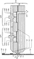
도 1a는 가변 내부 체적을 가지고 간헐적 코팅을 위한 본 발명의 장치(100)를 도시한 단면도이다. 노즐 슬롯(103)은(도면에 도시되지 않는) 절단부(cut-out) 를 가진 삽입 필름(108)에 의해 2개의 노즐 조(nozzle jaws)(101,102)들사이에서 조정된다. 상기 삽입 필름(108)은 상기 노즐 조(101,102)의 전체 길이 및 폭에 걸쳐 연장되고 바람직하게 0.01 내지 3.00 mm, 바람직하게 0.05 mm 내지 1.0mm, 특히 바람직하게 0.3mm 내지 0.5mm의 두께를 갖는 금속으로 제조된다. 조립체내에서, (도면에 도시되지 않는) 절단부는 공급채널(107)로부터 출구 갭(130)까지 연장되는 공동을 형성한다. 이 경우, 상기 장치의 출구 갭(130)은 기질(170)의 이송 방향(U)에 대해 횡 방향으로 배열되고 기질(170)과 평행하게 배열된다.IA is a cross-sectional view of an
노즐 출구(130)의 상류 위치에서, 노즐 조(101)내에 개구부(123)가 제공되고, 상기 개구부(123)내에 조절유닛(120a)이 포함된다. 배열은 가요성 요소(121a)를 포함하고, 상기 가요성은 항복(yielding)되거나 구부러질 수 있는(bendable) 것을 의미하며 상기 가요성 요소는 밀봉 요소(122a), 액츄에이터(124a), 관련 평면 부착부(125a) 및 커버(126a)와 연결된다. 이를 위해, 탄성변형 가능한 가요성 요소(121a)는 상기 밀봉 요소(122a) 및 커버(126a)에 의해 개구부(123a)의 변부 영역들에서 노즐 조(101)내의 러그(lug)상의 제 위치로 고정되고 밀봉된다. 상기 노즐 슬롯(103)의 높이, 따라서 노즐 슬롯(103)의 전체 체적은 탄성변형 가능한 가요성 요소(121a)에 의해 변화될 수 있다. 가요성 요소(121a)의 변형 및 노즐 슬롯(103) 내의 가변 체적의 변형을 감시하기 위해, (도면에 도시되지 않는) 적절한 센서 시스템이 커버(126a)속에 일체로 구성된다.An opening 123 is provided in the
상기 가요성 요소(121a)의 중앙 영역에 액츄에이터(124a)가 설치된다. 상기 액츄에이터(124a)는 부착부(125a)에 의해 상기 가요성 요소(121a)와 접촉하고, 이에 따라 가요성 요소(121a)의 변형을 제어할 수 있다. 공급 펌프(feed pump )의 하중이 상기 노즐 슬롯으로부터 가해지는 상기 가요성 요소(121a)가, 상기 액츄에이터(124a)의 카운터 하중 또는 증가하는 카운터 하중에 의해 제 위치(제2 스위치 위치) 및 형상으로 유지되고, 다시 말해 액츄에이터는 가요성 요소(121a)를 노즐 슬롯(130)을 향해 가압하지만, 노즐 슬롯(130)은 이에 따라 수축되지 않는다.An
추가의 조정 유닛(120b)이 동일한 노즐 조(103)속에 유사하게 일체구성되고, 상기 추가 조정 유닛은 조정 유닛(120b)과 공급 채널(107) 사이에 배열된다. 결과적으로, 상기 노즐 슬롯(130)의 체적이 유사하게 변화할 수 있고, 상기 조절 유닛(120b)에 의해 노즐 슬롯(103)내부의 체적은 증가하지 못 한다. 압력은 연속적으로 떨어지고 상기 노즐 몸체(100) 또는 노즐 슬롯(103) 내에서 상기 공급 채널(107)로부터 출구 갭(130)까지 형성된다. 전단 응력(T)은 노즐 슬롯(103)을 통해 유동 한계(Tf)를 초과한다.A further adjusting
도 1b는 출구 갭에서 기하학적 비율들을 개략적으로 도시한다.Figure 1b schematically shows the geometric ratios in the exit gap.
도 1b는 출구 갭(130)에서 기하학적 비율들을 개략적으로 도시한다. 노즐 슬롯(103)은 기질(170)의 이송 방향(U)에 대해 횡 방향으로 배열되고 기질(170)과 평행하게 배열되며 노즐 몸체(100)의 출구 갭(130)으로서 끝나고, 상기 출구 슬롯(130)은 노즐 슬롯(103)을 통해 공급 채널(107)(도 1a를 참고)과 유동 연결(flow connection)된다. 이 경우, 출구 갭(165)의 폭은 삽입 필름(108)의 두께에 해당하고, 상류위치의 노즐 립(131) 및 하류위치의 노즐 립(132) 사이의 공간을 한정한다. 코팅 공정 동안, 출구 갭(130) 또는 두 개의 노즐 립(131,132) 및 움직이는 기질(170) 사이에 액체 연결부(liquid bridge)(160)가 형성된다. 상기 액체 연결부(165)의 두께는 원하는 습식 필름(wet film)의 두께(164)보다 크다.1B schematically illustrates the geometric ratios at the
도 1c는, 중단(interruption) 단계가 개시되는 동안, 가변 내부 체적을 가진 간헐적인 코팅을 위한 본 발명에 따른 장치를 도시한 개략도이다.1C is a schematic diagram illustrating an apparatus according to the present invention for intermittent coating with variable internal volume during the initiation of the interruption step.
도 1c는 중단 단계가 개시되는 동안 본 발명에 따른 장치를 개략적으로 도시한다. 이 경우, 액츄에이터(124a)를 비활성화시키면, 가요성 요소(121a)는 시스템 압력(p)의 작용에 의해 간단하게 변형되어 노즐 슬롯(103)의 이 부분에서 체적이 증가하게 된다.Figure 1c schematically shows a device according to the invention during the start of the interruption step. In this case, when the
추가로 유입되는 코팅 물질은 노즐 슬롯(103)의 가변 체적속으로 포함되도록 이 부분에서 시간 경과에 따라 체적이 증가하는 변화가 설정된다. 동시에, 출구 갭(130)을 향하는 노즐 슬롯(103)내의 압력은 즉시 대략적으로 주위 압력으로 떨어진다. 그 결과, 액체 연결부(160)(도 1b를 참고)가 노즐 슬롯(103)에서 떨어지게(torn off)된다. 따라서, 출구 갭(130)을 향하는 전단 응력(T)은 유동 한계(Tf)보다 작다. 그러나, 전단 응력 전단 응력(T)은 출구 갭(130)에 대한 방향을 변화시키지 않고 0보다 크다. 동시에, 액츄에이터(124a)를 작동시키면, 상기 가요성 요소(121b)는 변형되어 노즐 슬롯(103)의 변형을 발생시킨다. 그 결과, 노즐 슬롯(103)에 수축이 발생하여 국소적으로 압력이 상승하게 된다. 따라서, 코팅 물질의 전단 응력(T)은 증가하고 코팅 물질의 유속이 증가한다. 따라서, 국소적인 압력 변동이 발생하여, 국소 유동 속도가 직접적으로 발생되고 코팅 공정을 최적상태로 제어한다.A further increase in the volume of the coating material is set in this portion so that the coating material is introduced into the variable volume of the
도 1d는 중단 단계가 종료하거나 코팅 단계가 개시되는 동안 가변적인 내부 체적을 가지며 간헐적 코팅을 위한 본 발명의 장치를 도시한 개략도이다.Figure 1D is a schematic diagram illustrating the apparatus of the present invention for intermittent coating with a variable internal volume during the end of the interruption step or during the initiation of the coating step.
계속되는 코팅 단계가 개시될 때, 출구 갭(130) 또는 가변 내부 체적은 조정 유닛(120a)에 의해 가요성 요소(121a)의 영역에서 감소된다.When a subsequent coating step is initiated, the
코팅 물질 체적의 경미한 변화 및 그에 따른 코팅 물질의 증가된 압력은 코팅 물질의 유동 한계(flow limit)(Tf)를 극복하기에 충분하다. 출구 갭(130) 및 가요성 요소(124a)의 주위 영역 사이에서 노즐 슬롯(103)의 코팅 물질에 여전히 존재하는 전단 응력(T)은 필요한 초기 임펄스를 감소시킨다. 상기 가변 내부 체적은 전체 코팅 단계에 걸쳐 분산되어 연속적으로 감소되거나, 노즐 슬롯(103)이 감소하지만 삽입필름(108)에 의해 설정된 갭 폭(133)보다 작아지지 않도록 가요성 요소(121)가 변형된다.The slight change in coating material volume and thus the increased pressure of the coating material is sufficient to overcome the flow limit (Tf) of the coating material. The shear stress T still present in the coating material of the
따라서, 상기 가변 내부 체적내에 이미 존재하는 코팅 물질은 이동한 체적 유량(q)으로 공급된다. 결정된 습윤 필름 두께(164)에 대해, 공급된 코팅 물질의 속도는 기질 속도로 조정된다. 따라서, 상기 조정은 시간 경과에 따라 액츄에이터(124a)로부터 발생된 반대 하중의 이동 속도 또는 전파에 의해 발생된다.Thus, the coating material already present in the variable inner volume is supplied at the moved volumetric flow rate (q). For the determined
도 2a는 이중 갭(double gap)을 포함하고 가변 내부 체적을 가진 간헐적인 코팅을 위한 본 발명의 장치를 도시한 개략도이다.FIG. 2A is a schematic diagram illustrating the apparatus of the present invention for intermittent coating with a double gap and a variable internal volume. FIG.
도 2a에 도시된 것처럼, 장치(200)의 노즐 조(101,102)들은 바람직하게 쐐기 형상의 격실 판 (104) 주위에서 대칭구조를 가진 조정 유닛 (120a,120b,120c,120d)과 함께 배열된다. As shown in FIG. 2A, the
따라서, 추가적인 삽입 필름(108)을 이용하여, 상기 격실 판 (104) 및 노즐 조(102) 사이에 또 다른 노즐 슬롯(103)이 형성된다.Thus, another
그 결과, 동일한 코팅 물질을 사용하여 두 배의 속도로 코팅 물질을 코팅할 수있을뿐만 아니라 두 개의 서로 다른 코팅 물질로 동시에 코팅이 수행될 수 있다. 또한 두 개의 층들이 코팅될 수 있다. As a result, not only is it possible to coat the coating material at twice the rate with the same coating material, but also the coating can be carried out simultaneously with two different coating materials. Two layers can also be coated.
도 2b는 이중 갭을 포함하고 본 발명에 따른 장치의 출구 갭에서 기하학적 비율을 개략적으로 도시한다.Fig. 2b schematically shows the geometric ratio in the exit gap of the device according to the invention, including the double gaps.
또한, 도 2b는 출구 갭(130)에서 기하학적 비율을 개략적으로 도시한다. 노즐 슬롯(103) 각각은, 노즐 몸체 (200)의 출구 갭(130)으로서 (도 2b를 참고) 기질(170)의 이송 방향(U)에 대해 횡 방향으로 배열되고 상기 기질(170)과 평행하게 끝나며, 각 출구 갭(130)은 관련 노즐 슬롯(103)을 통해 관련 공급 채널(107)(도 2를 참고)과 유동 연결된다.Figure 2b also schematically illustrates the geometric ratio at the
이 경우, 해당 출구 갭(133)의 폭은 삽입 필름(108)의 두께에 해당되고, 상류위치의 노즐 립(131)과 하류위치의 노즐 립(132) 사이의 이격거리를 형성한다.In this case, the width of the
따라서, 다른 코팅 물질이 공급되는 또 다른 출구 갭(133)이 형성된다. 코팅 과정 동안, 유체 연결부(160)가 관련 출구 갭(130) 또는 2개의 노즐 립(131,132) 및 이동중인 기질(170)사이에 형성된다. 그러나, 여기에서 액체 연결부(160)는 도 1의 액체 연결부와 다르다. 액체 연결부(160)의 두께는, 2개의 부분 유동(qa,qb)들의 결과라는 점에서 도 1b의 액체 연결부와 유사하다. 따라서, 습윤 필름 두께(164)는 코팅 물질(A)의 습윤 필름 두께(166) 및 코팅 물질(B)의 습윤 필름 두께(167)의 결과이다.Thus, another
100, 200.....간헐적인 코팅을 위한 장치,
101,102.....노즐 조,
103.....노즐 슬롯,
104.....격실 판,
105.....노즐 조 요홈,
107.....공급 채널,
108.....삽입 필름,
120.....조정 유닛,
121.....가요성 요소,
122.....밀봉 요소,
123.....개구부,
124.....액츄에이터,
125.....위치, 액츄에니터의 선형 또는 평면 부착부,
126.....커버,
130.....출구 갭,
131.....상류 위치의 노즐 립,
132.....하류 위치의 노즐 립,
133.....넓은 출구 갭,
160.....액체 연결부,
161.....습식 필름, 기질상의 액체 필름,
162.....단부 변부, 필름 단부 변부,
163.....개시 변부, 필름 개시 변부,
164.....습식 필름 두께,
165.....액체 연결부(160)의 두께,
166.....코팅 물질(A)의 습식 필름 두께,
167.....코팅 물질(B)의 습식 필름 두께,
170.....기질,
U.....기질의 이동방향,
q, qa, qb.....이동한 체적 유동,
p.....압력.100, 200 ..... Apparatus for intermittent coating,
101, 102 ..... nozzle set,
103 ..... Nozzle slots,
104 ..... compartment plate,
105 ..... Nozzle groove,
107 ..... supply channel,
108 ..... Insertion film,
120 ..... adjustment unit,
121 ..... Flexibility factor,
122 ..... sealing element,
123 ..... opening,
124 ..... Actuator,
125 ..... position, linear or planar attachment of actuators,
126 ..... cover,
130 ..... exit gap,
131 ..... Nozzle lip in the upstream position,
132 ..... Nozzle lip in downstream position,
133 ..... wide exit gap,
160 ..... liquid connection,
161 ..... Wet film, liquid film on substrate,
162 ..... end edge portion, film end edge portion,
163 ..... initiation margin, film initiation margin,
164 ..... wet film thickness,
The thickness of the
166 ..... Wet film thickness of coating material (A)
167 ..... Wet film thickness of the coating material (B)
170 ..... substrate,
U ..... direction of substrate migration,
q, qa, qb ..... Moved volume flow,
p ..... pressure.
Claims (7)
적어도 두 개의 노즐 조(101,102)들을 가진 노즐 몸체(100)를 포함하고, 상기 노즐 조(101,102)들사이에 절단부를 가진 삽입 필름(108)이 제공되며, 상기 삽입 필름(108)의 절단부는 상기 노즐 몸체(10)내에서 노즐 슬롯(103)을 형성하고, 상기 기질(170)의 이송 방향(U)에 대해 횡 방향으로 연장되고 상기 기질(170)에 대해 평행하게 배열된 상기 노즐 슬롯(103)이 출구 갭(130)에서 끝나며, 상기 출구 갭(130)은 상기 노즐 슬롯(103)에 의해 공급 채널(107)과 유동 연결되고, 적어도 한 개의 노즐 조(101,102)가 적어도 두 개의 개구부(123a,123b)들을 가지며 상기 개구부들은 상기 공급 채널 및 출구 갭(130)사이에서 직렬로 상기 노즐 슬롯(103)속으로 형성되고, 각각의 개구부는 탄성 변형가능한 요소(121a,121b)에 의해 상기 노즐 슬롯(103)을 향하여 유체 밀봉 상태로 밀폐되며, 각각의 탄성 변형가능한 요소(121a,121b)는 한쪽 측부에서 상기 노즐 슬롯(103)내에서 코팅 물질과 작동하며 연결되고 다른 한쪽 측부에서 상기 노즐 슬롯(103)을 향해 액츄에이터(124a,124b)와 작동하며 연결되며, 상기 노즐 조(101,102)의 개구부(123a,123b)들이 상기 공급 채널(107)로부터 상기 출구 갭(130)까지 코팅 물질의 유동 방향(q)을 따라 연속적으로 배열되는 것을 특징으로 하는 장치.
An apparatus for intermittently coating a substrate moving in a transport direction (U) with respect to the apparatus,
An injection molding machine comprising a nozzle body (100) having at least two nozzle assemblies (101,102) and provided with an insert film (108) having cutouts between the nozzle assemblies (101,102) A nozzle slot 103 formed in the nozzle body 10 and extending transversely with respect to the transport direction U of the substrate 170 and arranged parallel to the substrate 170; Is terminated at an outlet gap 130 and the outlet gap 130 is fluidly connected to the supply channel 107 by the nozzle slot 103 and at least one nozzle set 101,102 has at least two openings 123a And 123b, the openings being formed in the nozzle slot 103 in series between the supply channel and the outlet gap 130, each opening being defined by the elastically deformable elements 121a, Is sealed in a fluid-tight state toward the base 103, The deformable elements 121a and 121b are operatively connected to the coating material in the nozzle slot 103 at one side and operatively connected to the actuators 124a and 124b at the other side towards the nozzle slot 103 , Wherein openings (123a, 123b) of the nozzle tanks (101, 102) are successively arranged along the flow direction (q) of the coating material from the supply channel (107) to the outlet gap (130).
2. The apparatus according to claim 1, wherein a compartment plate (104) is arranged between the nozzle tanks (101,102), and an insert film (108) having cutouts is provided between each of the nozzle tanks (101,102) and the compartment plate (104) Characterized in that the relative insertion films (108, 108b) form nozzle slots (103, 103b) in the nozzle body (200) in each case.
A device according to any one of the preceding claims, wherein the thickness of the insert film (108) is between 0.01 mm and 3.00 mm.
4. The apparatus according to any one of claims 1 to 3, wherein the openings (123a, 123b) are arranged in only one nozzle set (101) and the opposed nozzle set (102) has no openings.
이동한 체적 유동(q)는 상기 방법의 모든 단계들에 걸쳐서 일정하게 유지되고 상기 방법은
a) 노즐 슬롯(103)을 통해 상기 공급 채널(107)로부터 출구 갭(130)까지 코팅 물질을 연속적으로 공급하는 단계,
b) 액츄에이터(124a)를 비활성화시켜서 개구부(123a)내에서 가요성 요소(121a)를 언로딩(unloading)하는 단계,
c) 액츄에이터(124b)를 활성화시켜서 개구부(123b)내에서 가요성 요소(121b)를 동시에 로딩(loading)하는 단계,
d) 액츄에이터(124a)를 활성화시켜서 개구부(123a)내에서 가요성 요소(121a)를 로딩하는 단계,
e) 액츄에이터(124b)를 비활성화시켜서 개구부(123b)내에서 가요성 요소(121b)를 언로딩하는 단계를 포함하는 것을 특징으로 하는 방법.
A method for intermittently coating a moving substrate using an apparatus according to any one of claims 1 to 3,
The transferred volumetric flow q is kept constant throughout all steps of the method,
a) continuously supplying the coating material from the supply channel (107) to the outlet gap (130) through the nozzle slot (103)
b) deactivating the actuator 124a to unload the flexible element 121a within the opening 123a,
c) activating the actuator 124b to simultaneously load the flexible element 121b within the opening 123b,
d) activating the actuator 124a to load the flexible element 121a within the opening 123a,
e) deactivating the actuator (124b) to unload the flexible element (121b) within the opening (123b).
이동한 체적 유동(qa,qb)는 상기 방법의 모든 단계들에 걸쳐서 일정하게 유지되고 상기 방법은,
a) 노즐 슬롯(103)을 통해 상기 공급 채널(107a,107b)로부터 출구 갭(130a,130b)까지 코팅 물질을 연속적으로 공급하는 단계,
b) 액츄에이터(124a,124c)를 비활성화시켜서 개구부(123a,123c)내에서 가요성 요소(121a,121c)를 언로딩하는 단계,
c) 액츄에이터(124b,124d)를 활성화시켜서 개구부(123b,123d)내에서 가요성 요소(121b,121d)를 동시에 로딩하는 단계,
d) 액츄에이터(124a,124c)를 활성화시켜서 개구부(123a,123c)내에서 가요성 요소(121a,121c)를 로딩하는 단계,
e) 액츄에이터(124b,124d))를 비활성화시켜서 개구부(123b,123d)내에서 가요성 요소(121b,121d)를 동시에 언로딩하는 단계를 포함하는 것을 특징으로 하는 방법.
A method for intermittently coating a moving substrate using an apparatus according to claim 2 or 3,
The transferred volume flow (q a , q b ) remains constant throughout all steps of the method,
a) continuously supplying the coating material from the supply channels (107a, 107b) through the nozzle slots (103) to the outlet gaps (130a, 130b)
b) deactivating the actuators 124a, 124c to unload the flexible elements 121a, 121c in the openings 123a, 123c;
c) activating the actuators 124b and 124d to simultaneously load the flexible elements 121b and 121d within the openings 123b and 123d,
d) activating the actuators 124a, 124c to load the flexible elements 121a, 121c in the openings 123a, 123c,
e) actuating the actuator (124b, 124d) to unload the flexible elements (121b, 121d) simultaneously in the openings (123b, 123d).
이동한 체적 유동(qa,qb)는 상기 방법의 모든 단계들에 걸쳐서 일정하게 유지되고 상기 방법은,
a) 노즐 슬롯(103a,103b)을 통해 상기 공급 채널(107a,107b)로부터 출구 갭(130a,130b)까지 코팅 물질을 연속적으로 공급하는 단계,
b) 액츄에이터(124a)를 비활성화시켜서 개구부(123a)내에서 가요성 요소(121a)를 언로딩하는 단계,
c) 액츄에이터(124b)를 활성화시켜서 개구부(123b)내에서 가요성 요소(121b)를 동시에 로딩하는 단계,
d) 액츄에이터(124c)를 활성화시켜서 개구부(123c)내에서 가요성 요소(121c)를 로딩하는 단계,
e) 액츄에이터(124d))를 비활성화시켜서 개구부(123d)내에서 가요성 요소(121d)를 동시에 언로딩하는 단계
f) 액츄에이터(124c)를 비활성화시켜서 개구부(123c)내에서 가요성 요소(121c)를 언로딩하는 단계,
g) 액츄에이터(124d)를 활성화시켜서 개구부(123d)내에서 가요성 요소(121d)를 동시에 로딩하는 단계,
h) 액츄에이터(124a)를 활성화시켜서 개구부(123a)내에서 가요성 요소(121a)를 로딩하는 단계,
e) 액츄에이터(124b)를 비활성화시켜서 개구부(123b)내에서 가요성 요소(121b)를 동시에 언로딩하는 단계를 포함하는 것을 특징으로 하는 방법.
A method for intermittently coating a moving substrate using an apparatus according to claim 2 or 3,
The transferred volume flow (q a , q b ) remains constant throughout all steps of the method,
a) continuously supplying the coating material from the supply channels (107a, 107b) through the nozzle slots (103a, 103b) to the outlet gaps (130a, 130b)
b) deactivating the actuator 124a to unload the flexible element 121a within the opening 123a,
c) activating the actuator 124b to simultaneously load the flexible element 121b within the opening 123b,
d) activating the actuator 124c to load the flexible element 121c within the opening 123c,
e) actuating the actuator 124d) to simultaneously unload the flexible element 121d within the opening 123d
f) deactivating the actuator 124c to unload the flexible element 121c within the opening 123c,
g) activating the actuator 124d to simultaneously load the flexible element 121d within the opening 123d,
h) activating the actuator 124a to load the flexible element 121a within the opening 123a,
e) deactivating the actuator 124b to simultaneously unload the flexible element 121b within the opening 123b.
Applications Claiming Priority (3)
| Application Number | Priority Date | Filing Date | Title |
|---|---|---|---|
| DE102014112977.6A DE102014112977A1 (en) | 2014-09-09 | 2014-09-09 | Method and device for intermittent coating |
| DE102014112977.6 | 2014-09-09 | ||
| PCT/EP2015/001633 WO2016037674A1 (en) | 2014-09-09 | 2015-08-07 | Method and device for intermittent coating |
Publications (1)
| Publication Number | Publication Date |
|---|---|
| KR20170053616A true KR20170053616A (en) | 2017-05-16 |
Family
ID=53836532
Family Applications (1)
| Application Number | Title | Priority Date | Filing Date |
|---|---|---|---|
| KR1020177004097A KR20170053616A (en) | 2014-09-09 | 2015-08-07 | Method and device for intermittent coating |
Country Status (7)
| Country | Link |
|---|---|
| US (1) | US10399112B2 (en) |
| EP (1) | EP3191230B1 (en) |
| JP (1) | JP2017532194A (en) |
| KR (1) | KR20170053616A (en) |
| CN (1) | CN106575743A (en) |
| DE (1) | DE102014112977A1 (en) |
| WO (1) | WO2016037674A1 (en) |
Cited By (1)
| Publication number | Priority date | Publication date | Assignee | Title |
|---|---|---|---|---|
| KR20200011227A (en) * | 2018-07-24 | 2020-02-03 | 주식회사 엘지화학 | Slot die coater adjusting device for adjusting the distance between the upper discharge port and the lower discharge port of the slot die coater and Electrode active material coating system comprising the same |
Families Citing this family (2)
| Publication number | Priority date | Publication date | Assignee | Title |
|---|---|---|---|---|
| JP6929186B2 (en) * | 2017-10-10 | 2021-09-01 | 日産自動車株式会社 | Manufacturing method of battery electrodes |
| US10948824B2 (en) * | 2018-06-28 | 2021-03-16 | Taiwan Semiconductor Manufacturing Co., Ltd. | Dispensing nozzle design and dispensing method thereof |
Family Cites Families (16)
| Publication number | Priority date | Publication date | Assignee | Title |
|---|---|---|---|---|
| US4938994A (en) | 1987-11-23 | 1990-07-03 | Epicor Technology, Inc. | Method and apparatus for patch coating printed circuit boards |
| DE19516697C2 (en) * | 1995-05-06 | 1998-12-17 | Ford Werke Ag | Device for applying pasty media |
| JPH0985149A (en) * | 1995-09-25 | 1997-03-31 | Sony Corp | Coating applicator |
| JPH09164357A (en) * | 1995-12-18 | 1997-06-24 | Dainippon Screen Mfg Co Ltd | Liquid coater |
| US6455105B1 (en) * | 1997-09-05 | 2002-09-24 | Toshiba Kikai Kabushiki Kaisha | Intermittent coating system and intermittent coating method |
| JPH1176901A (en) * | 1997-09-05 | 1999-03-23 | Toshiba Mach Co Ltd | Coating device |
| JP2981876B2 (en) * | 1998-01-12 | 1999-11-22 | 井上金属工業株式会社 | Coating equipment |
| US7105203B1 (en) * | 1999-02-10 | 2006-09-12 | Mastsushita Electric Industrial Co., Ltd. | Intermittent coating apparatus and intermittent coating method |
| JP3491196B2 (en) | 1999-02-10 | 2004-01-26 | 松下電器産業株式会社 | Intermittent coating device and intermittent coating method |
| JP2002028553A (en) * | 2000-07-12 | 2002-01-29 | Sony Chem Corp | Coating apparatus |
| JP4596614B2 (en) * | 2000-08-04 | 2010-12-08 | 東芝機械株式会社 | A device that intermittently coats the surface of a substrate |
| US6688580B2 (en) | 2001-10-31 | 2004-02-10 | Nordson Corporation | Adjustable die for a fluid dispenser and method |
| US6811613B2 (en) * | 2001-11-26 | 2004-11-02 | Tokyo Electron Limited | Coating film forming apparatus |
| FI113197B (en) * | 2002-09-20 | 2004-03-15 | Metso Paper Inc | The applicator |
| DE102004012476B4 (en) | 2004-03-15 | 2007-10-25 | Dilo Trading Ag | Process for producing a lithium polymer cell and a lithium polymer battery |
| JP2007044643A (en) * | 2005-08-11 | 2007-02-22 | Inoue Kinzoku Kogyo Co Ltd | Die coating apparatus |
-
2014
- 2014-09-09 DE DE102014112977.6A patent/DE102014112977A1/en not_active Ceased
-
2015
- 2015-08-07 US US15/509,510 patent/US10399112B2/en not_active Expired - Fee Related
- 2015-08-07 CN CN201580043848.5A patent/CN106575743A/en not_active Withdrawn
- 2015-08-07 JP JP2017513500A patent/JP2017532194A/en active Pending
- 2015-08-07 KR KR1020177004097A patent/KR20170053616A/en unknown
- 2015-08-07 EP EP15750249.3A patent/EP3191230B1/en active Active
- 2015-08-07 WO PCT/EP2015/001633 patent/WO2016037674A1/en active Application Filing
Cited By (1)
| Publication number | Priority date | Publication date | Assignee | Title |
|---|---|---|---|---|
| KR20200011227A (en) * | 2018-07-24 | 2020-02-03 | 주식회사 엘지화학 | Slot die coater adjusting device for adjusting the distance between the upper discharge port and the lower discharge port of the slot die coater and Electrode active material coating system comprising the same |
Also Published As
| Publication number | Publication date |
|---|---|
| JP2017532194A (en) | 2017-11-02 |
| EP3191230A1 (en) | 2017-07-19 |
| WO2016037674A1 (en) | 2016-03-17 |
| CN106575743A (en) | 2017-04-19 |
| DE102014112977A1 (en) | 2016-03-10 |
| US20170252773A1 (en) | 2017-09-07 |
| US10399112B2 (en) | 2019-09-03 |
| EP3191230B1 (en) | 2019-10-09 |
Similar Documents
| Publication | Publication Date | Title |
|---|---|---|
| JP2021533714A (en) | Multiplexed charge / discharge battery management system | |
| JP5875487B2 (en) | Manufacturing method and manufacturing apparatus for lithium ion secondary battery | |
| EP3252862A1 (en) | Secondary battery | |
| US10468662B2 (en) | Production method and production apparatus of electrode for secondary battery, electrode for secondary battery, and secondary battery | |
| KR20170053616A (en) | Method and device for intermittent coating | |
| JP6628505B2 (en) | Method and apparatus for manufacturing electrode for secondary battery and method for manufacturing secondary battery | |
| CN105531855B (en) | The manufacture device of electrical storage device and the manufacture method of electrical storage device | |
| US20190267634A1 (en) | Electrochemical devices and methods for making same | |
| JP2014191876A (en) | Electrode for lithium ion secondary battery, lithium ion secondary battery, and apparatus and method for manufacturing electrode for battery | |
| CN107615523B (en) | Secondary battery electrode, secondary battery manufacturing method and manufacturing device | |
| JP2005211871A (en) | Die nozzle and electrode plate producing method | |
| JPH1055799A (en) | Manufacture of sheet-shaped electrode plate and nonaqueous electrolyte battery | |
| EP3229973B1 (en) | Method and device for intermittent coating | |
| CN113613797A (en) | Electrode paste coating method and apparatus including pressure regulating member | |
| JP3643447B2 (en) | Sheet electrode manufacturing method and non-aqueous electrolyte battery | |
| JP3893731B2 (en) | Intermittent application device | |
| JP2017054762A (en) | Electrode for secondary battery, manufacturing method of secondary battery, and manufacturing method of electrode for secondary battery | |
| KR20170093343A (en) | Coating Device of Electrode Mix Having Main Discharging Member and Auxiliary Discharging Member and Method for Coating with the Same | |
| US20200266418A1 (en) | Gap section multilayer electrode profile | |
| EP4239706A1 (en) | Electrode coating apparatus and electrode coating method | |
| WO2022211102A1 (en) | Active material supply device, and method for manufacturing electrode for battery | |
| WO2023167339A1 (en) | Apparatus for producing battery electrode and method for producing battery electrode | |
| WO2023171772A1 (en) | Battery electrode manufacturing device and battery electrode manufacturing method | |
| JP2000149929A (en) | Device for intermittent coating of coating material to substrate and production equipment of electrode plate for battery | |
| CN220420828U (en) | Battery cell |